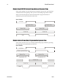
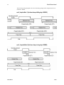
1
4 Megapixel 30/60 fps Area Scan Cameras
27-Oct-08
03-032-20044-01
www.dalsa.com
Falcon
4M30 and 4M60
Camera User’s Manual
PT-41-04M60-XX-R
PT-21-04M30-XX-R
Falcon 4M Camera Manual
2
© 2008 DALSA. All information provided in this manual is believed to be accurate and reliable. No
responsibility is assumed by DALSA for its use. DALSA reserves the right to make changes to this
information without notice. Reproduction of this manual in whole or in part, by any means, is prohibited
without prior permission having been obtained from DALSA.
About DALSA
DALSA is an international high performance semiconductor and electronics company that designs,
develops, manufactures, and markets digital imaging products and solutions, in addition to providing
semiconductor products and services. DALSA’s core competencies are in specialized integrated circuit and
electronics technology, software, and highly engineered semiconductor wafer processing. Products and
services include image sensor components; electronic digital cameras; vision processors; image processing
software; and semiconductor wafer foundry services for use in MEMS, high-voltage semiconductors,
image sensors and mixed-signal CMOS chips. DALSA is listed on the Toronto Stock Exchange under the
symbol “DSA”. The Company has its corporate offices in Waterloo, ON and over 1000 employees
worldwide.
For further information not included in this manual, or for information on DALSA’s extensive line of
image sensing products, please call:
DALSA Sales Offices
Waterloo
Europe
Asia Pacific
605 McMurray Rd
Waterloo, ON N2V 2E9
Canada
Tel: 519 886 6000
Fax: 519 886 8023
www.dalsa.com
[email protected]
Breslauer Str. 34
D-82194 Gröbenzell (Munich)
Germany
Tel: +49 - 8142 – 46770
Fax: +49 - 8142 – 467746
www.dalsa.com
[email protected]
Ikebukuro East 13F
3-4-3 Higashi-Ikebukuro
Toshima-ku, Tokyo 170-0013
Japan
Tel: 81 3 5960 6353
Fax: 81 3 5960 6354 (fax)
www.dalsa.com
[email protected]
Waterloo
Europe
Asia Pacific
605 McMurray Rd
Waterloo, ON N2V
2E9
Canada
Tel: 519 886 6000
Fax: 519 886 8023
www.dalsa.com
[email protected]
Breslauer Str. 34
D-82194 Gröbenzell (Munich)
Germany
Tel: +49 - 8142 – 46770
Fax: +49 - 8142 – 467746
www.dalsa.com
[email protected]
Ikebukuro East 13F
3-4-3 Higashi-Ikebukuro
Toshima-ku, Tokyo 170-0013
Japan
Tel: 81 3 5960 6353
Fax: 81 3 5960 6354 (fax)
www.dalsa.com
[email protected]
DALSA Worldwide Operations
Camera Link is a trademark registered by the Automated Imaging Association, as chair of a committee of
industry members including DALSA.
03-032-20044-01
DALSA
3
Falcon 4M Camera Manual
Contents
Introduction to the 4 Megapixel Falcon Cameras _________________________________ 5
1.1 Camera Highlights.......................................................................................................................................................5
1.2 Camera Performance Specifications ............................................................................................................................6
1.3 Cosmetic Specifications ................................................................................................................................................8
1.4 Image Sensor and Pixel Readout ................................................................................................................................11
1.5 Responsivity.................................................................................................................................................................12
Camera Hardware Interface________________________________________________ 14
2.1 Installation Overview...................................................................................................................................................14
2.2 Input/Output Connectors and LED...............................................................................................................................15
2.2.1 LED Status Indicator ..............................................................................................................................15
2.2.2 Camera Link ..........................................................................................................................................16
2.2.3 Power Connector....................................................................................................................................18
Software Interface: How to Control the Camera __________________________________ 20
3.1 First Power Up Camera Settings..................................................................................................................................22
3.2 Saving and Restoring Settings.....................................................................................................................................23
3.3 Camera Output Format ...............................................................................................................................................24
3.3.1 How to Configure Camera Output..........................................................................................................24
3.3.2 Setting the Camera Link Mode ..............................................................................................................25
3.3.3 Setting the Camera Link Strobe Frequency ...........................................................................................26
3.4 Setting Exposure Mode, Frame Rate and Exposure Time............................................................................................26
3.4.1 Non-concurrent vs. concurrent modes of operation...............................................................................26
3.4.2 Setting the Exposure Mode ....................................................................................................................28
3.4.2 Setting the Frame Rate..........................................................................................................................31
3.4.3 Setting the Exposure Time.....................................................................................................................31
3.4.4 Enabling EXSYNC Debounce Circuit .......................................................................................................32
3.5 Snapshot Modes...........................................................................................................................................................33
3.6 Setting a Vertical Window of Interest ..........................................................................................................................38
3.7 Flat Field Correction ....................................................................................................................................................42
3.7.1 Selecting Factory or User Coefficients ....................................................................................................45
3.7.2 Enabling Pixel Coefficients.....................................................................................................................45
3.7.3 Selecting the Calibration Sample Size...................................................................................................46
3.7.4 Performing FPN Calibration..................................................................................................................46
3.7.5 Performing PRNU Calibration ...............................................................................................................48
DALSA
03-032-20044-01
4
Falcon 4M Camera Manual
3.7.6 Saving, Loading and Resetting Coefficients...........................................................................................49
3.7.7 Returning Pixel Coefficient Information ................................................................................................50
3.8 Offset and Gain Adjustments.......................................................................................................................................51
3.9 Generating a Test Pattern ...........................................................................................................................................54
Optical and Mechanical Considerations ________________________________________ 60
4.1 Mechanical Interface....................................................................................................................................................60
4.2 Lens Mounts.................................................................................................................................................................61
4.3 Optical Interface ..........................................................................................................................................................61
Troubleshooting ________________________________________________________ 64
5.1 Common Solutions.......................................................................................................................................................64
5.2 Troubleshooting Using the Serial Interface.................................................................................................................65
5.3 Specific Solutions .........................................................................................................................................................65
5.4 Product Support...........................................................................................................................................................67
Camera Link™ Reference, Timing, and Configuration Table __________________________ 68
Error Handling and Command List ___________________________________________ 74
B1 All Available Commands ..............................................................................................................................................74
EMC Declaration of Conformity______________________________________________ 80
Revision History ________________________________________________________ 82
Index _______________________________________________________________ 84
03-032-20044-01
DALSA
5
Falcon 4M Camera Manual
1
Introduction to the 4
Megapixel Falcon
Cameras
1.1 Camera Highlights
Features
•
4 megapixels, 2352 (H) x 1728 (V) resolution, CMOS area camera
•
Global shutter (non-rolling) for crisp images
•
60 fps model or 30 fps model
•
Vertical windowing for faster frame rate
•
7.4 µm x 7.4 µm pixel pitch
•
4 x 80 MHz or 2 x 80 MHz data rates
•
Nominal broadband responsivity of 18.4 DN/(nJ/cm2)
•
Good NIR response
•
8 or 10 bit selectable output
•
Dynamic range of 57 dB
•
Base or Medium Camera Link™ interface
•
RoHS and CE compliant
Programmability
DALSA
•
A simple ASCII protocol controls gain, offset, frame rates, trigger mode, test pattern
output, and camera diagnostics.
•
The serial interface (ASCII, 9600 baud, adjustable to 19200, 57600, 115200) operates
through Camera Link.
03-032-20044-01
Falcon 4M Camera Manual
6
Description
The 4 megapixel Falcon cameras are our most advanced high-speed area array cameras.
With data rates up to 320 MHz, these cameras are capable of capturing low smear images
at incredibly fast speeds. Programmable features and diagnostics are accessible through
the Camera Link™ MDR26 connector.
Applications
The 4M Falcon cameras are ideal for applications requiring high speed, superior image
quality, and high responsivity. Applications include:
•
PCB inspection
•
3D solder paste inspection
•
2D and 3D wafer bump inspection
•
Semiconductor wafer inspection
•
Flat panel display inspection
•
Industrial metrology
•
Traffic management
•
General machine vision
Models
The Falcon 4M camera is available in the following models:
Falcon 4M Camera Models Overview
Model Number
Description
PT-21-04M30-XX-R
4M resolution, 2 sensor taps, 30 frames per second, RoHS
compliant.
PT-41-04M60-XX-R
4M resolution, 4 sensor taps, 60 frames per second, RoHS
compliant.
1.2 Camera Performance Specifications
Camera Performance Specifications
Feature / Specification
Notes
Resolution
2352 (H) x 1728 (V) pixels
Pixel Fill Factor
45%
Effective fill factor with
microlenses
60%
# of Lines per Frame
1728 lines
Output Format (# of taps)
2 (4M30) or 4 (4M60)
Optical Interface
Back Focal Distance
Sensor die to mounting
plate
03-032-20044-01
Notes
6.56 mm
5
DALSA
7
Falcon 4M Camera Manual
Optical Interface
Notes
Sensor Alignment
x
y
z
0z
±0.10 mm
±0.10 mm
±0.25 mm
±0.3°
F-mount adapter available
M42 x 1
Lens Mount
Lens Mount Hole
Mechanical Interface
Notes
Camera Size
94 x 94 x 48 mm
Mass
<550 g
Connectors
power connector 6 pin male Hirose
data connector 2 x MDR26 female
Electrical Interface
Notes
Input Voltage
+12 to +15 Volts
Power Dissipation
10 typ, 14 Watts max
6
Operating Temperature
0 to 50 °C
Data Output Format
8 or 10 user selectable bits
Output Data Configuration
Base or Medium Camera Link
1
Operating Ranges
Notes
Minimum Frame Rate
1 Hz
Maximum Frame Rate
60.4 Hz(4M60)
30.6 Hz (4M30)
Data Rate
80 MHz
Dynamic Range
(10 bits @ nominal gain)
682:1 typ.
Random Noise
1.5 typ, 2.0 max DN rms
Broadband Responsivity
18.4 typ DN/(nJ/cm )
7
DC Offset
0 DN
7
Antiblooming
>1000x saturation
FPN
0.5 typ, 1.0 max DN rms
PRNU
1.5 typ, 2.6 max DN rms
8
Integral non-linearity
<2% DN
3
4
2
2
2
Saturation Equivalent Exposure
55 typ nJ/cm
Noise Equivalent Exposure
80 typ pJ/cm2
Saturation Output Amplitude
1023 DN
Test conditions unless otherwise noted:
•
DALSA
sem 2 (exposure mode 2).
03-032-20044-01
Falcon 4M Camera Manual
8
•
ssf 55 (55 frames per second rate).
•
set 2000 (2 millisecond exposure time).
•
sem 2 (Exposure mode 2) .
•
Full frame/window.
•
clm 16 (4 tap, 10 bit).
•
sot 320 (80 MHz camera link strobe).
•
efd 1 (Snapshot mode 1).
•
snd 1 (Number of fast frame dumps = 1).
•
Light Source: Broadband Quartz Halogen, 3250K (3050 to 3450), with a 750 nm cutoff
filter .
•
Ambient test temperature 25°C.
•
Average output 840 DN.
•
Flat field correction (FFC) turned on.
Notes:
1.
Measured at the front plate.
2.
Based on output at 1023 DN.
3.
Output over 10-90%.
4.
Snapshot mode 0 allows for marginally higher frame rates.
5.
Optical distance.
6.
+12V consumes the least amount of power.
7.
With FFC on. Responsivity is not calibrated when FCC is turned off.
8.
Measured at half saturation.
1.3 Cosmetic Specifications
Please note, for this section only, the following values are considered preliminary
information and subject to change without notice.
Sensor Cosmetic Specifications
The following table highlights the current cosmetic specifications for the DALSA sensor
used inside the Falcon 4M60 and 4M30 cameras. The monochrome sensor has 4
megapixels (2352 x 1728), global shuttering and is capable of 60 fps.
Sensor Cosmetic Specifications
Cosmetic Specification
Hot pixel defects
03-032-20044-01
Maximum Number of Defects
1
Single pixel defects
100
Clusters defects
No limit (refer to the Note below)
Spot defects
1
Column defects
0
Row defects
0
DALSA
9
Falcon 4M Camera Manual
Definition of cosmetic specifications
Hot pixel defect
Pixel whose signal, in dark, deviates by more than 400 DN (10 bits) from the average of all
the pixels.
Single pixel defect
Pixel whose signal, at nominal light (illumination at 50% of saturation), deviates by more
than ±30% from its neighboring pixels.
Cluster defect
A grouping of at most 8 pixel defects within an area of 3 x 3 pixels.
Spot defect
A grouping of 9 pixel defects within an area of 3 x 3 pixels.
Column defect
A column which has 12 pixel defects in a 1*12 kernel.
Row defect
An horizontal grouping of more than 4 pixel defects between at least 2 good pixels on
both sides, where single good pixels between 2 defective pixels are considered defective.
Test conditions
•
Digital gain – 1X.
•
Nominal light = illumination at 50% of saturation.
•
Frame Rate = 60 fps (Falcon 4M60), 30 fps (Falcon 4M30)
•
Integration time = 15 ms
•
Ambient Temperature of 25°C
Note: While the number of clusters is not limited by a maximum number, the total
number of defective pixels cannot exceed 100. Therefore, you could have 12 clusters of 8
in size (12 x 8 = 96), but you could not have 13 clusters of 8 in size (13 x 8 = 104).
The probability of 12 clusters of 8 is negligible and is only used as an example.
DALSA
03-032-20044-01
Falcon 4M Camera Manual
10
Camera Cosmetic Specification
Beyond sensor cosmetic testing, the camera is placed under additional testing to more
closely examine potential cosmetic defects due to the sensor glass. This test examines the
difference between two images. One image is taken under collimated light and the second
image is taken under diffuse light. Any difference represents blemishes on the glass
rather than blemishes on the sensor die surface.
Camera Cosmetic Specifications - Glass
Cosmetic Spec
Difference
Spec
Glass defects
5%
Cluster Size
Max Number of Defects
9
0
Definition of blemishes
Glass defects
A group of pixels exceeding the given cluster size and the difference between the
collimated and diffuse light settings. Images are taken at nominal light (illumination at
50% of the linear range). A cluster is defined as a grouping of pixels. A grouping of pixels
refers to adjacent pixels or pixels that touch.
In addition, the camera is examined against the following cosmetic specifications.
Camera Cosmetic Specifications – Sensor & Glass
Cosmetic Specification
Maximum Number of Defects
Dark pixel defects (>300DN)
50
Dark pixel defects (>600DN)
1
Single pixel defects
100
Definition of cosmetic specifications
Dark pixel defects
Pixel whose signal, in dark, exceeds the given threshold (10 bits).
Single pixel defect
Pixel whose signal, at nominal light (illumination at 50% of saturation), deviates by more
than ±30% from its neighboring pixels.
Test conditions
03-032-20044-01
•
Digital gain – 1X.
•
Nominal light = illumination at 50% of saturation.
•
Frame Rate = 60 fps (Falcon 4M60), 30 fps (Falcon 4M30).
•
Integration time = 15 ms.
•
Ambient Temperature of 25°C.
DALSA
11
Falcon 4M Camera Manual
Note: all of the above sensor and camera cosmetic specifications are with flat field turned
off (epc 0 0). There are no post-flat-field (epc 1 1) camera cosmetic specifications.
1.4 Image Sensor and Pixel Readout
The camera uses DALSA’s new DCR2417M, 4 megapixel, 2352 x 1728 CMOS sensor.
Figure 1: 4 Tap Sensor Block Diagram
Note: As viewed from the front of the camera without lens. The bottom of the camera has
a ¼-20 tripod mount.
Pixel
1
Row 1728
Column 1
Tap 1
Row 1728
Column 2
Tap 2
Row 1728
Column 3
Tap 3
Row 1728
Column 4
Tap 4
Row 1728 Row 1728 Row 1728 Row 1728
Column 2349 Column 2350 Column 2351 Column 2352
Tap 1
Tap 2
Tap 3
Tap 4
Row 1727
Column 1
Tap 1
Row 1727
Column 2
Tap 2
Row 1727
Column 3
Tap 3
Row 1727
Column 4
Tap 4
Row 1727 Row 1727 Row 1727 Row 1727
Column 2349 Column 2350 Column 2351 Column 2352
Tap 4
Tap 1
Tap 2
Tap 3
Row 2
Column 1
Tap 1
Row 2
Column 2
Tap 2
Row 2
Column 3
Tap 3
Row 2
Column 4
Tap 4
Row 2
Row 2
Row 2
Row 2
Column 2349 Column 2350 Column 2351 Column 2352
Tap 1
Tap 4
Tap 2
Tap 3
Row 1
Column 1
Tap 1
Row 1
Column 2
Tap 2
Row 1
Column 3
Tap 3
Row 1
Column 4
Tap 4
Row 1
Row 1
Row 1
Row 1
Column 2349 Column 2350 Column 2351 Column 2352
Tap 4
Tap 2
Tap 3
Tap 1
Pixel read out direction is left to right then bottom to top
Camera Readout and Coordinates
The camera readout begins with pixel 1 and reads out successive pixels from left to right
until the entire row is completed. This process is repeated with each successive row in the
frame. Pixel coordinates are expressed as column and rows, where the first pixel’s
coordinates are 1, 1 and the last pixel’s coordinates are 2352, 1728.
Figure 2: 4M60 Pixel Readout Detail
Pixel
1
DALSA
Row 1
Column 1
Tap 1
Row 1
Column 2
Tap 2
Row 1
Column 3
Tap 3
Row 1
Column 4
Tap 4
03-032-20044-01
Falcon 4M Camera Manual
12
Figure 3: 4M30 Pixel Readout Detail
Row 1
Column 1
Tap 1
Pixel
1
Row 1
Column 2
Tap 2
Row 1
Column 3
Tap 1
Row 1
Column 4
Tap 2
1.5 Responsivity
Figure 4: Spectral Responsivity
Spectral Responsivity at Coarse Gain = 0 dB, Fine Gain = 45
Responsivity (DN/(nJ/cm2))
25
20
15
10
5
0
300
400
500
600
700
800
900
1000
1100
Wavelength (nm)
Note: Responsivity is calibrated with fcc on.
03-032-20044-01
DALSA
13
Falcon 4M Camera Manual
Figure 5: Effective Quantum Efficiency
Effective Quantum Efficiency
Fill Factor x Quantum Efficiency (% )
60
50
40
30
20
10
0
300
400
500
600
700
800
900
1000
1100
W a ve le ngth (nm )
DALSA
03-032-20044-01
Falcon 4M Camera Manual
14
2
Camera Hardware
Interface
2.1 Installation Overview
When setting up your camera, you should take the following steps:
This installation
overview assumes you
have not installed any
system components yet.
1)
Power down all equipment.
2)
Following the manufacturer’s instructions, install the frame grabber (if applicable). Be
sure to observe all static precautions.
3)
Install any necessary imaging software.
4)
Before connecting power to the camera, test all power supplies.
5)
Inspect all cables and connectors prior to installation. Do not use damaged cables or
connectors. The camera may be damaged as a result.
6)
Connect Camera Link and power cables.
7)
After connecting cables, apply power to the camera.
8)
Check the diagnostic LED. If the camera is operating correctly, the LED will flash for
approximately 30 seconds and then turn solid green. See 2.2.1 LED Status Indicator
for a description of LED states.
You must also set up the other components of your system, including light sources,
camera mounts, computers, optics, encoders, and so on.
A note on Camera Link cable quality and length
The maximum allowable Camera Link cable length depends on the quality of the cable
used and the Camera Link strobe frequency. Cable quality degrades over time as the
cable is flexed. As the Camera Link strobe frequency is increased, the maximum
allowable cable length will decrease.
DALSA does not guarantee good imaging performance with low quality cables of any
length. In general, DALSA recommends the use of high quality cables in lengths less than
10 meters.
03-032-20044-01
DALSA
15
Falcon 4M Camera Manual
2.2 Input/Output Connectors and LED
The camera uses:
•
A diagnostic LED for monitoring the camera. See LED Status Indicator in section 2.2.1
LED Status Indicator for details.
•
Two high-density 26-pin MDR26 connectors for Camera Link control signals, data
signals, and serial communications. Refer to section 2.2.2 Camera Link
•
Data Connector for details.
•
One 6-pin Hirose connector for power. Refer to section 2.2.3 Power Connector for
details.
Figure 6: Input and Output
Diagnostic LED
CONTROL
DATA 1
Camera Link (Base Configuration)
Camera Link (Medium Configuration)
DATA 2
POWER
+12V to +15V
WARNING: Ensure that all the correct voltages at full load are present at the camera end of the
power (irrespective of cable length) according to the pinout defined in section 2.2.3 Power
Connector.
2.2.1 LED Status Indicator
The camera is equipped with a red/green LED used to display the operational status of
the camera. The table below summarizes the operating states of the camera and the
corresponding LED states.
When more than one condition is active, the LED indicates the condition with the highest
priority. Error and warning states are accompanied by corresponding messages further
describing the current camera status.
Status LED
Color of Status LED
DALSA
Meaning
Flashing Green
Camera initialization or executing a time consuming command
Solid Green
Camera is operational and functioning correctly
Flashing Red
Fatal Error. System voltage out of tolerance.
Solid Red
Warning. Loss of functionality (e.g. external SRAM failure)
03-032-20044-01
Falcon 4M Camera Manual
16
2.2.2 Camera Link
Data Connector
Figure 7: Camera Link MDR26 Connector
MDR26 Female
13
1
26
14
M at ing Par t: 3M 334-31 ser ies
Cable: 3M 14X 26-SZ LB-X X X -0LC* *
The Camera Link interface is implemented as either Base or Medium configuration in the
Falcon 4M cameras.
Select the camera configuration with the clm command described in the section Setting
the Camera Link Mode.
The following tables provide this camera’s principal Camera Link information. See
Appendix A for the complete DALSA Camera Link configuration table, and refer to the
DALSA Web site, mv.dalsa.com, for the official Camera Link documents.
03-032-20044-01
Camera Link Hardware Configuration Summary
Configuration 8 Bit Ports
Serializer
Supported
Bit Width
Number
of Chips
Number of MDR26
Connectors
Base
A, B, C
28
1
1
Medium
A, B, C, D, E, F
28
2
2
BASE
Configuration
Mode (set with
clm command)
Port Definition
Port A
Bits 0 thru 7
Port B
Bits 0 thru 7
Port C
Bits 0 thru 7
Mode 2
2 Tap 8 bit
Tap 1 LSB..Bit 7
Tap 2 LSB..Bit7
xxxxxxx
Mode 3
2 Tap 10 bit
Tap 1 LSB.. Bit 7
Tap 1 Bits 8,9
Tap 2 Bits 8,9
Tap 2 LSB..Bit 7
Medium
Configuration
Mode
Port Definition
Port A
Bits 0 thru
7
Port B
Bits 0 thru
7
Port C
Bits 0 thru
7
Port D
Bits 0
thru 7
Port E
Bits 0
thru 7
Port F
Bits 0
thru 7
Mode 15
4 Tap 8 bit
Tap 1
LSB..Bit 7
Tap 2
LSB..Bit 7
Tap 3
LSB..Bit 7
Tap 4
LSB...Bit 7
xxxxxxxx
xxxxxxxx
Mode 16
4 Tap 10 bit
Tap 1
LSB.. Bit 7
Tap 1 Bits 8,9
Tap 2 Bits 8,9
Tap 2
LSB..Bit 7
Tap 4
LSB…Bit 7
Tap 3
LSB…Bit
7
Tap 3 Bit
8,9
Tap 4 Bit
8,9
DALSA
17
Falcon 4M Camera Manual
Camera Link Connector Pinout
Medium Configuration
Up to an additional 2 Channel Link Chips
Base Configuration
One Channel Link Chip + Camera
Control + Serial Communication
Camera
Right Angle Channel
Connector
Frame
Link Signal
Grabber
Connector
Camera
Right Angle
Connector Frame Grabber
Connector
Channel Link
Signal
1
1
inner shield
1
1
inner shield
14
14
inner shield
14
14
inner shield
2
25
Y0-
2
25
X0-
15
12
Y0+
15
12
X0+
3
24
Y1-
3
24
X1-
16
11
Y1+
16
11
X1+
4
23
Y2-
4
23
X2-
17
10
Y2+
17
10
X2+
5
22
Yclk-
5
22
Xclk-
18
9
Yclk+
18
9
Xclk+
6
21
Y3-
6
21
X3-
19
8
Y3+
19
8
X3+
7
20
100 ohm
7
20
SerTC+
20
7
terminated
20
7
SerTC-
8
19
Z0-
8
19
SerTFG-
21
6
Z0+
21
6
SerTFG+
9
18
Z1-
9
18
CC1-
22
5
Z1+
22
5
CC1+
10
17
Z2-
10
17
CC2+
23
4
Z2+
23
4
CC2-
11
16
Zclk-
11
16
CC3-
24
3
Zclk+
24
3
CC3+
12
15
Z3-
12
15
CC4+
25
2
Z3+
25
2
CC4-
13
13
inner shield
13
13
inner shield
26
26
inner shield
26
26
inner shield
Notes:
*Exterior Overshield is connected to the shells of the connectors on both ends.
**3M part 14X26-SZLB-XXX-0LC is a complete cable assembly, including connectors.
Unused pairs should be terminated in 100 ohms at both ends of the cable.
Inner shield is connected to signal ground inside camera
DALSA Camera Control Configuration
Signal
Configuration
DALSA
CC1
EXSYNC
CC2
Reserved for future use
CC3
Reserved for future use
CC4
Window toggle
03-032-20044-01
Falcon 4M Camera Manual
18
Input Signals, Camera Link
The camera accepts control inputs through the Camera Link MDR26F connector.
The camera ships in internal sync, internal programmed integration (exposure mode 2),
and Camera Link mode 16 (4M60) or 3 (4M30).
EXSYNC
IMPORTANT:
Camera readout is
triggered on the falling
edge of EXSYNC.
Frame rate can be programmed using the serial interface. The external control signal
EXSYNC is optional and enabled through the serial interface. This camera uses the falling
edge of EXSYNC to trigger frame readout. Section 3.3 Camera Output Format details
how to set frame times, exposure times, and camera modes.
Output Signals, Camera Link
These signals indicate when data is valid, allowing you to clock the data from the camera
to your acquisition system. These signals are part of the Camera Link configuration and
you should refer to the DALSA Camera Link Implementation Road Map, available at
http://mv.dalsa.com/, for the standard location of these signals.
Clocking Signal
Indicates
LVAL (high)
Outputting valid line
DVAL (high)
Valid data
STROBE (rising edge)
Valid data
FVAL (high)
Outputting valid frame
•
The camera internally digitizes to 10 bits and outputs 8 MSB or all 10 bits depending
on the camera’s Camera Link operating mode.
•
For a Camera Link reference and timing definitions refer to Appendix A on page 68.
2.2.3 Power Connector
Figure 8: Hirose 6-pin Circular Male—Power Connector
Hirose 6-pin Circular Male
6
1
5
2
4
3
Mat ing Par t: HIRO SE
HR10A -7P-6S
Hirose Pin Description
Pin Description
Pin
Description
1
12 to 15V
4
GND
2
12 to 15V
5
GND
3
12 to 15V
6
GND
The camera requires a single voltage input (12 to 15V).
!
03-032-20044-01
WARNING: When setting up the camera’s power supplies follow these guidelines:
•
Protect the camera with a fast-blow fuse between power supply and camera.
•
Power surge limit at 3 A.
•
12 V power supply. Nominal 0.85 A load resulting in ~20 A/s current ramp rate
•
Power supply current limit needs to be set at >3 A.
DALSA
19
Falcon 4M Camera Manual
•
Do not use the shield on a multi-conductor cable for ground.
•
Keep leads as short as possible to reduce voltage drop. Long power supply leads may
falsely indicate that the power supply is within the recommended voltage range even
when the camera at the connector is actually being supplied with much less voltage.
•
Use high-quality linear supplies to minimize noise.
•
Use an isolated type power supply to prevent LVDS common mode range violation.
Note: Performance specifications are not guaranteed if your power supply does not meet
these requirements. See section 1.3 for power requirements.
!
WARNING: It is extremely important that you apply the appropriate voltages to your
camera. Incorrect voltages will damage the camera. Protect the camera with a fast-blow
fuse between power supply and camera.
Visit the mv.dalsa.com Web site for a list of companies that make power supplies that
meet the camera’s requirements. The companies listed should not be considered the only
choices.
DALSA
03-032-20044-01
Falcon 4M Camera Manual
20
3
Software Interface: How
to Control the Camera
All camera features can be controlled through the serial interface. The camera can also be
used without the serial interface after it has been set up correctly. Functions available
include:
•
Controlling basic camera functions such as gain and sync signal source
•
Data readout control
•
Generating a test pattern for debugging
•
The serial interface uses a simple ASCII-based protocol and the camera does not
require any custom software.
Serial Protocol Defaults
•
8 data bits
•
1 stop bit
•
No parity
•
No flow control
•
9.6Kbps
•
Camera does not echo characters
Command Format
When entering commands, remember that:
03-032-20044-01
•
A carriage return <CR> ends each command.
•
The camera will answer each command with either <CR><LF> OK > or Error x:
Error Message >. The > is always the last character sent by the camera.
•
The camera accepts both upper and lower case commands.
•
The following parameter conventions are used in the manual:
•
i = integer value
f = real number
m = member of a set. Value must be entered exactly as displayed on help screen.
DALSA
21
Falcon 4M Camera Manual
s = string
t = tap id
x = pixel column number
y = pixel row number
Example: to retrieve the current camera settings
gcp <CR>
Setting Baud Rate
Purpose:
Syntax:
Sets the speed in bps of the serial communication port.
Syntax Elements:
m
sbr m
Baud rate. Available baud rates are: 9600 (Default), 19200,
57600, and 115200.
Notes:
Example:
•
Power-on rate is always 9600 baud.
•
The rc (reset camera) command will not reset the camera to
the power-on baud rate and will reboot using the last used
baud rate.
sbr 57600
Camera Help Screen
For quick help, the camera can retrieve all available commands and parameters through
the serial interface.
To view the help screen, use the command:
Syntax:
h
The help screen lists all commands available. Parameter ranges displayed are the ranges
available under the current operating conditions. The ranges depend on the current
camera operating conditions, and you may not be able to enter these values.
Example Help Screen (4M60)
ccf correction calculate fpn
clm camera link mode
cpa correction prnu algorithm
csn coefficient set number
css correction set sample
dpc display pixel coefficients
edc enable debounce circuit
efd enable frame dump
epc enable pixel coefficients
gcm get camera model
gcp get camera parameters
gcs get camera serial
gcv get camera version
gfc get fpn coefficient
DALSA
m
2/3/15/16/
mi
2/4/:1-1023
i
0-15
m
32/64/128/256/512/1024/
xyxy 1-2352:1-1728:1-2352:1-1728
m
0/1/
m
0/1/2/
ii
0-1:0-1
xy
1-2352:1-1728
03-032-20044-01
Falcon 4M Camera Manual
22
gpc get prnu coefficient
gsf get signal frequency
h help
lpc load pixel coefficient
rc reset camera
rfs restore factory settings
rpc reset pixel coefficients
rus restore user settings
sao set analog offset
sbr set baud rate
sdo set digital offset
sem set exposure mode
set set exposure time
sfc set fpn coefficient
snd set number frame dumps
sot set output throughput
spc set prnu coefficient
ssb set subtract background
ssf set sync frequency
ssg set system gain
svm set video mode
vt verify temperature
vv verify voltages
wfc write fpn coefficients
wpc write prnu coefficients
wse window start end
wss window set sequence
wts window trigger source
wus write user settings
OK>
xy
m
1-2352:1-1728
1/4/
ti
m
ti
m
f
xyi
i
m
xyi
ti
f
ti
i
0-0:0-511
9600/19200/57600/115200/
0-2:0-2048
2/3/4/6/7/
492-999989 [us]
1-2352:1-1728:0-1023
1-7
260/320/
1-2352:1-1728:0-12287
0-2:0-511
1.0-60.4 [Hz]
0-2:0-65535
0-12
iixyxy 0-0:1-1:1-1:1-1725:2352-2352:4-1728
i
0-1
m
1/2/
Retrieving Camera Settings
To retrieve current camera settings, use the command:
Syntax:
gcp
3.1 First Power Up Camera Settings
When the camera is powered up for the first time, it operates using the following factory
settings:
PT-41-04M60
03-032-20044-01
•
Flat field coefficients enabled (calibrated in exposure mode 2, 55 fps, and an
exposure time of 2 ms [non-concurrent readout and integration], snapshot mode
1, number of fast frame dumps = 1)
•
Exposure mode 2
•
60 fps
DALSA
23
Falcon 4M Camera Manual
•
9995 µs exposure time
•
Camera Link mode 16 (Medium configuration, 4 taps. 10 bits)
•
80 MHz pixel rate (320 MHz total throughput)
•
Full window (2352 x 1728)
•
Snapshot mode 1 enabled (EFD 1)
PT-21-04M30
•
Flat field coefficients enabled (calibrated in exposure mode 2, 29 fps, and
exposure time of 2 ms [non-concurrent readout and integration], snapshot mode
1, number of fast frame dumps = 1)
•
Exposure mode 2
•
30 fps
•
14992 µs exposure time
•
Camera Link mode 3 (Medium configuration, 2 taps. 10 bits)
•
80 MHz pixel rate (160 total throughput)
•
Full window (2352 x 1728)
•
Snapshot mode 1 (EFD 1)
3.2 Saving and Restoring Settings
Figure 9: Saving and Restoring Overview
Factory
Settings
rus
User
Settings
rfs
Current
Session
wus
Factory Settings
You can restore the original factory settings at any time using the command rfs.
Note: This command does not restore flat field coefficients. Refer to the lpc command.
User Settings
You can save or restore your user settings to non-volatile memory using the following
commands.
DALSA
03-032-20044-01
Falcon 4M Camera Manual
24
•
To save all current user settings to non-volatile memory, use the command wus. The
camera will automatically restore the saved user settings when powered up.
•
To restore the last saved user settings, use the command rus.
Note: on power-up the camera will restore the FFC coefficients where csn is pointing to.
Example:
csn 10 (and choose coeff set 10)
wus
rc or power cycle
Coefficients from csn 10 are restored
Current Session Settings
These are the current operating settings of your camera. These settings are stored in the
camera’s volatile memory and will not be restored once you power down your camera or
issue a reset camera command (rc). To save these settings for reuse at power up, use the
command wus.
3.3 Camera Output Format
3.3.1 How to Configure Camera Output
The 4M Falcon cameras offer great flexibility when configuring your camera output.
Using the clm command, you determine the camera’s Camera Link configuration,
number of output taps, and bit depth. Using the sot command, you determine the
camera’s output rate. These two commands work together to determine your final camera
output configuration.
4M30 Data Readout Configurations
Camera Link Mode Configuration
(Controlled by clm command)
Command
Camera Link
Configuration
Camera Link Taps
Bit
Depth
clm 2
Base
2 Camera Link taps
where:
1 = Taps 1+3
2 = Taps 2+4
8
2 Camera Link taps
where:
1 = Taps 1+3
2 = Taps 2+4
10
clm 3
03-032-20044-01
Pixel Rate
Configuration
(Controlled by
sot command)
Base
sot 130 = 65
MHz strobe
sot 160 = 80
MHz strobe
sot 130 = 65
MHz strobe
sot 160 = 80
MHz strobe
DALSA
25
Falcon 4M Camera Manual
4M60 Data Readout Configurations
Camera Link Mode Configuration (Controlled by clm
command)
Command
Camera Link
Configuration
Camera Link Taps
Bit
Depth
clm 2
Base
2 Camera Link taps
where:
1 = Taps 1+3
2 = Taps 2+4
8
2 Camera Link taps
where:
1 = Taps 1+3
2 = Taps 2+4
10
4 Camera Link taps
where:
1 = Tap 1
2 = Tap 2
3 = Tap 3
4 = Tap 4
8
4 Camera Link taps
where:
1 = Tap 1
2 = Tap 2
3 = Tap 3
4 = Tap 4
10
clm 3
clm 15
clm 16
Base
Medium
Medium
Pixel Rate
Configuration
(Controlled by
sot command)
sot 130 = 65
MHz strobe
sot 160 = 80
MHz strobe
sot 130 = 65
MHz strobe
sot 160 = 80
MHz strobe
sot 260 = 65
MHz strobe sot
320 = 80 MHz
strobe
sot 260 = 65
MHz strobe
sot 320 = 80
MHz strobe
3.3.2 Setting the Camera Link Mode
Purpose:
Sets the camera’s Camera Link configuration, number of Camera
Link taps and data bit depth. Refer to the tables above for a
description of each Camera Link mode.
Syntax:
clm m
Syntax Elements:
m
Output mode to use:
2: Base configuration, 2 taps, 8 bit output
3: Base configuration, 2 taps, 10 bit output
15: Medium configuration, 4 taps, 8 bit output (4M60 only)
16: Medium configuration, 4 taps, 10 bit output (4M60 only)
Notes:
Example:
DALSA
•
To retrieve the current Camera Link mode, use the
command gcp
•
For details on line times and frame readout times when
using a window of interest, refer to following table.
clm 3
03-032-20044-01
Falcon 4M Camera Manual
26
3.3.3 Setting the Camera Link Strobe Frequency
Purpose:
Sets the camera link strobe frequency. Refer to the How to
Configure Camera Output section, above, for a description of how
camera link strobe frequency relate to the camera’s Camera Link
mode.
Syntax:
sot m
Syntax Elements:
m
If using Camera Link mode 2 or 3:
130: 65 MHz camera link strobe with a total throughput of 130
MHz
160: 80 MHz camera link strobe with a total throughput of 160
MHz
If using Camera Link 15 or 16 (4M60 only):
260: 65 MHz camera link strobe with a total throughput of 260
MHz
320: 80 MHz camera link strobe with a total throughput of 320
MHz
To retrieve the current throughput, use the command gcp or
get sot.
Notes:
•
Example:
sot 260
3.4 Setting Exposure Mode, Frame Rate and
Exposure Time
Overview
You have a choice of operating in one of three exposure modes. To select how you want
the camera’s frame rate to be generated:
1.
You must first set the camera’s exposure mode using the sem command.
2.
Next, if operating in exposure mode 2 use the command ssf to set the frame rate and
the set command to set the exposure time if in exposure mode 2 or 6.
3.4.1 Non-concurrent vs. concurrent modes of
operation
One of the main benefits of global shutter CMOS devices is that you have the choice to
operate the camera where integration and readout are concurrent or where integration
and readout are not concurrent. Integration refers to the time period that the camera can
be exposed to light and is often referred to as exposure time. Readout refers to the time it
takes to read out every pixel from the camera. For a 60 fps camera, such as the Falcon
4M60, the readout period is around 16.6 ms.
Concurrent mode is when the camera is integrating the current frame (Frame 1) and at the
same time is reading out the prior frame (Frame 0). By performing integration and
03-032-20044-01
DALSA
27
Falcon 4M Camera Manual
readout in parallel the Falcon 4M60 camera is capable of reaching 60fps. A timing
diagram helps to explain this mode of operation.
Concurrent Mode Timing Diagram
In concurrent mode, a low-to-high transition in the EXSYNC signal starts the integration
time, and a high-to-low transition in the EXSYNC signal starts the readout of image data.
As your frame period approaches the readout period, by reducing the Waiting time, the
Falcon 4M60 camera approaches its maximum frame rate of 60 fps.
In non-concurrent mode the integration and readout period do not overlap. While this
does impact your overall frame rate, the main benefit is that in non-concurrent mode you
eliminate or minimize imaging artifacts. DALSA recommends that, when possible,
operate the 4M60 camera in non-concurrent mode.
A timing diagram helps to explain the non-concurrent mode operation.
Non-concurrent Mode Timing Diagram
In non-concurrent mode, a low-to-high transition in the EXSYNC signal starts the
integration time, and a high-to-low transition in the EXSYNC signal starts the readout of
image data. This is the same as in concurrent mode. The difference between these two
modes is that you do not perform your next low-to-high transition of EXSYNC until
readout has completed. The waiting period can be reduced to 0 seconds by starting the
low-to-high transition immediately after readout is complete. The readout time is a fixed
amount of time that is dependant upon the mode of operation of the camera, but is
typically around 16.6 ms.
DALSA
03-032-20044-01
Falcon 4M Camera Manual
28
3.4.2 Setting the Exposure Mode
Purpose:
Sets the camera’s exposure mode allowing you to control your
sync, exposure time, and frame rate generation.
Syntax:
sem m
Syntax Elements:
m
Exposure mode to use. Factory default setting is 2.
Notes:
Refer to
•
Exposure Modes for a quick list of available modes or to the
following sections for a more detailed explanation.
•
To obtain the current value of the exposure mode, use the
command gcp.
Related Commands:
ssf, set
Example:
sem 4
Exposure Modes
Mode SYNC
03-032-20044-01
•
Programmable
Frame Rate
Programmable
Exposure Time
Description
2
Internal
Yes
Yes
Internal frame rate and
exposure time.
4
External
No
No
Smart EXSYNC.
6
External
No
Yes
EXSYNC pulse controlling
the frame rate.
Programmed exposure
time.
DALSA
29
Falcon 4M Camera Manual
Exposure Modes in Detail
Mode 2: Internally Programmable Frame Rate and Exposure Time
(Default)
The parameter being programmed (i.e. frame rate or exposure time) will be the driving
factor so that when setting the frame rate, exposure time will decrease, if necessary, to
accommodate the new frame rate. In reverse, the frame rate is decreased, if necessary,
when the exposure time entered is greater than the frame period.
Refer to Allowable Exposure Time Increments on page 32 for details on minimum
exposure time increments for this mode.
Note: The camera will not set frame periods shorter than the readout period.
Figure 10: Mode 2.
Internally-generated
Exsync
Exposure Time
Exposure Time
Programmable (SET)
Readout Time
Programmable (SET)
Readout Time
Programmable (SSF)
Programmable (SSF)
Frame Time
Frame Time
FVAL
DALSA
03-032-20044-01
Falcon 4M Camera Manual
30
Mode 4: Smart EXSYNC, External Frame Rate and Exposure Time
In this mode, EXSYNC sets both the frame period and the exposure time. The rising edge
of EXSYNC marks the beginning of the exposure and the falling edge initiates readout.
Refer to the Allowable Exposure Time Increments table on page 32 for details on
minimum exposure time increments for this mode.
Figure 11: Mode 4.
User Exsync
Exposure Time
Exposure Time
Readout Time
Readout Time
Frame Time
Frame Time
FVAL
Mode 6: External Frame Rate, Programmable Exposure Time
In this mode, the frame rate is set externally with the falling edge of EXSYNC generating
the rising edge of a programmable exposure time.
Figure 12: Mode 6.
User Exsync
Internally-generated Exsync
Exposure Time
Programmable (SET)
Exposure Time
Programmable (SET)
Readout Time
Frame Time
Frame Time
FVAL
03-032-20044-01
DALSA
31
Falcon 4M Camera Manual
3.4.2 Setting the Frame Rate
Purpose:
Syntax:
Sets the camera’s frame rate in frames per second (Hz).
Syntax Elements:
f
ssf f
Set the frame rate in Hz in a range from 1-60.4 (4M60 full
frame, 80 MHz cameralink strobe, efd 1) or 1-30.6 (4M30 full
frame, 80 MHz cameralink strobe, efd 1). Range increases
when using a vertical window of interest.
Notes:
•
Camera must be operating in exposure mode 2.
•
Allowable range is dependent on the current Camera Link
mode, snapshot mode, number of fast frame dumps and
window size. Refer to section above for more information on
Camera Link modes. Refer to section 3.5 for more information
on setting a window size.
•
Changing the frame rate will automatically adjust the
exposure time if necessary. The camera sends a warning when
this occurs.
•
Refer to section 3.3.3 Setting the for more information on how
to set the cameralink strobe.
•
When in SEM 2, the help screen (h) will shown the limits for
SSF
Related Commands:
sem, set
Example:
ssf 25.0
3.4.3 Setting the Exposure Time
Purpose:
Syntax:
Sets the camera’s exposure time in µs.
set f
Syntax Elements:
f
Floating point number in µs. Allowable range is 10-999989 µs.
The following table lists allowable increments.
Notes:
DALSA
•
Camera must be operating in exposure mode 2.
•
To retrieve the current exposure time, use the command gcp.
•
If you enter an exposure time outside of a valid range, the input
will not be accepted. Refer to the help screen (h command) for
the valid range.
•
If you enter an exposure time which overlaps with the frame
readout, the exposure time will automatically adjust to integral
units of exposure time increments (only in sem 2). The camera
adjusts the exposure without warning. Refer to Allowable
Exposure Time Increments.
•
Changing the exposure time will automatically adjust the frame
rate if necessary. The camera sends a warning when this occurs.
Related Commands:
sem, ssf, clm
Example:
set 5500
03-032-20044-01
Falcon 4M Camera Manual
32
Allowable Exposure Time Increments
Camera Link Mode
Allowable Exposure Time Increments
(clm command)
15 or 16
18.513 µs (80/65 MHz
camera link strobe)
when exposure time overlaps
frame readout
1 µs
when exposure time does not
overlap frame readout
2 or 3
37.038 µs (80 MHz
camera link strobe)
when exposure time overlaps
frame readout
45.638 µs (65 MHz
camera link strobe)
1 µs
when exposure time does not
overlap frame readout
Note: Although you must be operating the camera in exposure mode 2 to use the set
exposure time (set) command, the allowable exposure time increments listed above also
apply to exposure mode 4 (Smart EXSYNC) or 6 when exposure time overlaps frame
readout. This is because, in exposure mode 4, the falling edge is captured by the camera
every 18.513 µs for example in the case of clm 15 or 16, sot 320. In exposure modes
4 or 6 the exposure time effectively has an uncertainty of the allowable time increment.
Refer to section 3.4 Exposure Correction for more information on the clm and sot (sets
pixel rate) commands.
Refer to section Figure 10: Mode 2 on page 29 for an example where exposure time
overlaps frame readout.
3.4.4 Enabling EXSYNC Debounce Circuit
Purpose:
When enabled, the camera does not respond to any pulses on the
Exync input smaller than 1uS. The camera ships with this feature
disabled.
Syntax:
edc i
Syntax Elements:
i
EXSYNC debounce.
0 = EXSYNC debounce disabled
1 = EXSYNC debounce enabled
Notes:
Example:
03-032-20044-01
When disabled, the camera responds to the User EXSYNC input
the same as previous camera versions (00-R and non-RoHS).
edc 1
DALSA
33
Falcon 4M Camera Manual
3.5 Snapshot Modes
Purpose:
Optimizes camera timing for specific EXSYNC situations.
Syntax:
efd i
Syntax Elements:
i
Snapshot mode.
0 = Snapshot mode 0 (off)
1 = Snapshot mode 1
2 = Snapshot mode 2
Notes:
Example:
DALSA
efd 1
03-032-20044-01
Falcon 4M Camera Manual
34
Snapshot Mode
The Falcon 4M60 and Falcon 4M30 cameras include a feature called Snapshot Mode.
Snapshot Modes 1 and 2 allow the camera to produce usable images when intervals
between EXSYNCs are large (>200 ms).
Previously only snapshot mode 0 was available (no fast frame dump) which would
eventually result in a completely saturated ‘first’ image after a very long EXSYNC idle
period (seconds), as shown below.
First Frame Elevated Offset - efd 0
sem 4, External EXSYNC and exposure (smart EXSYNC)
By altering the internal timing, Snapshot Mode 1 performs a fast clearing of a frame
concurrently with integration. Thus, any dark current that caused elevated dark offset
levels, FPN or hot pixels, is cleared from the sensor prior to readout. The end result is that
the camera produces a usable first image.
With Snapshot Mode 1, please note that the timing of EXSYNC with respect to the
integration time has changed. The figure below illustrates Snapshot Mode 1 timing. The
difference is that the Integration Time, Z, is now equal to the EXSYNC high time, X, plus
the time it takes to clear the image, Y (plus 3.1 us of additional overhead). The total time
to clear the frame is Y (approximately 500 us). Therefore, the minimum integration time
in Snapshot Mode 1 is Y + 3.1 us. The exact value of Y is listed in the gcp screen as DUMP
TIME.
03-032-20044-01
DALSA
35
Falcon 4M Camera Manual
Snapshot Mode 1. Exposure concurrent with readout is allowed
If, having a minimum integration time of about 500 us is not acceptable, then Snapshot
Mode 2 can be used, below, which allows for integration times as low as 10 us at the
expense of concurrent integration and readout. Therefore, it is recommended to only use
Snapshot Mode 2 if your integration time must be below 500 us. This is also the reason
why Snapshot Mode 1 is the default mode. The following figure shows the timing
operation of Snapshot Mode 2. Notice that with Snapshot Mode 2 there is a delay of Y
between the rise of integration and when exposure begins.
Snapshot Mode 2. Exposure concurrent with readout is NOT allowed
DALSA
03-032-20044-01
36
Falcon 4M Camera Manual
The following timing diagrams show how the timing changes when snapshot modes are
enabled in sem 2.
sem 2, Snapshot Mode 1 (fast frame dump at falling edge of EXSYNC)
sem 2,. Snapshot Mode 2 (fast frame dump at rising edge of EXSYNC)
03-032-20044-01
DALSA
37
Falcon 4M Camera Manual
Determining the Y parameter
As mentioned, the Y parameter is around 500 us. The Y parameter depends upon the
number of rows used, whether the camera outputs at 80 MHz or 65 MHz, and whether
the camera being used is in 2 tap mode (Falcon 4M30) or 4 tap mode (Falcon 4M60). To
obtain the Y parameter, execute the gcp command. The camera should respond and
state:
“Frame Dump Time: 487.5 us”.
The 487.5 us used here represents the Y parameter for the factory settings of the Falcon
4M60.
What do I do if I cannot use either Snapshot Mode?
DALSA recommends that the camera is operated using a Snapshot Mode. However, in
some cases this may not be possible. Therefore, the camera can be setup to disable
Snapshot Mode (efd 0) and return the camera to the mode used prior to the
introduction of Snapshot Mode.
Different snapshot modes will produce different FPN and possibly different PRNU
patterns. The user is encouraged to match the snapshot mode with their corresponding
coefficients. This camera has 16 sets of coefficients, 8 factory and 8 user:
CSN
EFD
0, 3, 8, 11
1
1, 4, 9, 12
0
2, 5, 10, 13
2
6, 14
All coefficients = 0
7, 15
FPN/PRNU Test Pattern
FPN and PRNU coefficients for set 0 (csn 0) were calculated with EFD 1 and set 1 with
EFD 0 as shown above, etc. Set 6 has all coefficients set to 0/1 (FPN / PRNU) and set 7
has coefficients calculated from test patterns SVM 7 and 8. Sets 8 to 15 are user-writable
sets which mirror their factory counterparts as shown above.
Example:
DALSA
•
The user changes from snapshot mode 1 to 0.
•
In order to load the appropriate coefficients we must first point to the right set by
sending csn 1.
•
The coefficients need to be then loaded into volatile memory by sending lpc.
•
If the user wishes to load csn 1 on camera power-up then these settings should be
saved by sending wus.
03-032-20044-01
Falcon 4M Camera Manual
38
Set Number of Frame Dumps
Purpose:
Sets the number of fast-frame dumps to be used within snapshot
modes 1 or 2.
Syntax:
snd i
Syntax Elements:
i
Set number of frame dumps.
1-7
Only enabled during Snapshot modes (efd) 1 or 2.
Notes:
Example:
snd 3
When within snapshots modes 1 and 2 the user can choose to perform more than one fast
frame dump during a dump sequence. In some cases increasing the number of fast frame
dumps may help reduce the small residuals left behind after long EXSYNC idle times. In
general the user is recommended to use the factory default setting: snd 1.
Note that increasing the number of dumps will decrease the maximum frame rate that
can be achieved (this can be queried using the help screen in sem 2)..
3.6 Setting a Vertical Window of Interest
A window of interest is a subset of a full frame image that is desired as output from the
camera. Because the sensor is outputting only the designated window of interest, the
benefit is an increase in frame rate and a reduction in data volume.
To allow quick activation of new window coordinates, the camera allows you to preset
one sequence of window coordinates. These coordinates wait for a trigger and because
they have been preprogrammed, the new window is activated extremely quickly.
To set a window of interest
1.
Set the window activation method— either software activated (wts 1) or hardware
activated through CC4 (wts 2).
2.
Set the window coordinates, using the command wse 0 1 x y x y.
3.
Activate the window coordinates by:
o
transitioning CC4 to its complementary logic state when using an external
window control source ( wts = 2) .
or
o
4.
03-032-20044-01
transitioning to wss 0 or wss 1 depending on the complementary logic
state when using an internal window control source ( wts = 1).
When, or if, necessary, repeat steps 2 and 3 to set and activate a new window.
DALSA
39
Falcon 4M Camera Manual
The following graph illustrates the relationship of maximum frame rate versus sequence
size.
Figure 14: Maximum Frame Rate versus Sequence Size (efd 1, snd 1)
Max Frame Rate vs Vertical Window Size
Max Frame Rate (fps)
10000.0
1000.0
clm 16, sot 320
clm 3, sot 160
100.0
10.0
0
250
500
750 1000 1250 1500 1750 2000
Vertical Window Size (# lines)
Window Start End Command
Purpose:
Syntax:
Sets a window of interest.
wse q i x1 y1 x2 y2
Syntax Elements:
q
Window sequence id to use. In this camera, the sequence id is
always 0.
i
Window to set. You can only set one window, so this is always
1.
x1
Window start corner value. Since there is only a vertical (and not
horizontal) window of interest in this camera, this value is
always set to 1.
y1
Window start pixel number in a range from 1-1725 and must
belong to the following set: 1, 5, 9, …1725.
x2
Window end corner value. Since there is only vertical (and not
horizontal) window of interest in this camera, this value is
DALSA
03-032-20044-01
Falcon 4M Camera Manual
40
always set to 2352.
y2
Window end pixel number in range from 2-1728 and must
belong to the following set: 4, 8, 12, …1728.
Related Commands:
wss, wts
Example:
wse 0 1 1 13 2352 544
Table 1: Line Time and Frame Readout Time when using a Window of Interest
A rough estimate of the frame readout time, when using a large (100 lines+) window of
interest, can be found using the following formula:
Frame Readout Time= ( Number of Lines + 1) x Sensor Line Time
Where Sensor Line Time = 18.5us @ CLM 15/16, SOT 320/260
= 37.0us @ CLM 2/3, SOT 160
= 45.6us @ CLM 2/3, SOT 130
Setting the Window Sequence
Purpose:
To allow quick activation of new window coordinates, the camera
allows you to preset one sequence of window coordinates. These
coordinates wait for a trigger and because they have been
preprogrammed, the new window is activated extremely quickly.
This command sets the control method for toggling window
sequences.
Syntax:
wts i
Syntax Elements:
i
1
New window sequence is triggered through software
command wss.
2
New window sequence is triggered through Camera Link
inputs (CC4).
Related Commands:
wss
Example:
wts 2
Notes:
•
If you are using a hardware trigger (wts = 2), refer to Figure
15 for timing requirements.
•
If you are using a software trigger, refer to the next section for
command syntax and timing requirements.
Figure 15: Detailed Timing Requirements for Hardware Triggering New Window Sequence
EXSYNC
tsWLEV
Window Select (CC4)
03-032-20044-01
thWLEV
New Window Sequence
DALSA
41
Falcon 4M Camera Manual
Timing Parameters
Symbol
Definition
Min
Max
thWLEV
Window Level Hold Time- The Window Control Signals
must remain valid and constant after the EXSYNC
falling edge for at least the thWLEV time.
3
EXSYNCs
NA
tsWLEV
Window Level Set Time- The Window Control Signals
must remain valid and constant at least tsWLEV before
the EXSYNC falling edge.
3
EXSYNCs
NA
Toggling Window Sequences Using a Software
Trigger
Purpose:
To allow quick activation of new window coordinates, the camera
allows you to preset one sequence of window coordinates. These
coordinates wait for a trigger and because they have been
preprogrammed, the new window is activated extremely quickly.
This command loads a new window sequence.
Syntax:
wss m
Syntax Elements:
m
Window sequence trigger where changing from 0 to 1 (or vice
versa) toggles the current window sequence being used.
Related Commands:
wts
Example:
wss 0
Notes:
•
There is a delay between the issue of the wss command and the
time when the new window sequence is triggered (Figure 16)
•
When toggling windows, the camera discards the first frame
read out after the toggle. This prevents the camera from
sending out erroneous data.
•
Upon power up or reset of camera, the camera assumes that a
wss 0 has already been executed
Figure 16: Time Delay for New Window to Become Active when Using wss Command
Serial Communication
wss value
tDelay
Current Window Sequence
Window Sequence
New Window Sequence
Exsync
Timing Parameters
Symbol
Definition
tDelay
DALSA
This is the time delay that occurs to decode
the wss command.
Min
Max
1 EXSYNC
3 EXSYNCs
03-032-20044-01
Falcon 4M Camera Manual
42
3.7 Flat Field Correction
This camera has the ability to calculate correction coefficients in order to remove nonuniformity in the image. This video correction operates on a pixel-by-pixel basis and
implements a two point correction for each pixel. This correction can reduce or eliminate
image distortion caused by the following factors:
•
Fixed Pattern Noise (FPN)
•
Photo Response Non Uniformity (PRNU)
•
Lens and light source non-uniformity
Correction is implemented such that for each pixel:
Voutput =[(Vinput - FPN( pixel ) - digital offset) * PRNU(pixel) – Background Subtract] x System Gain
where
Voutput
=
digital output pixel value
Vinput
=
digital input pixel value from the sensor
PRNU( pixel)
=
PRNU correction coefficient for this pixel
FPN( pixel )
=
FPN correction coefficient for this pixel
Background Subtract
=
background subtract value
System Gain
=
digital gain value
The algorithm is performed in two steps. The fixed offset (FPN) is determined first by
performing a calculation without any light. This calibration determines exactly how much
offset to subtract per pixel in order to obtain flat output when the sensor is not exposed.
The white light (PRNU) calibration is performed next to determine the multiplication
factors required to bring each pixel to the required value (target) for flat, white output.
Video output is set slightly above the brightest pixel (depending on offset subtracted).
It is important to do the FPN correction first. Results of the FPN correction are used in the
PRNU procedure. We recommend that you repeat the correction when a temperature
change greater than 10°C occurs (the factory temp is about 37°C, vt command). In
snapshot mode 1, FPN coefficients are not particularly sensitive to changes in frame rate
or integration time. In snapshot modes 0 and 2, FPN coefficients will be sensitive to
changes in frame rate.
Note: If your
illumination or white
reference does not
extend the full field of
view of the camera,
the camera will send a
warning.
03-032-20044-01
PRNU correction requires a clean, white reference. The quality of this reference is
important for proper calibration. White paper is often not sufficient because the grain in
the white paper will distort the correction. White plastic or white ceramic will lead to
better balancing.
For best results, ensure that:
1)
60 Hz ambient light flicker is sufficiently low not to affect camera performance and
calibration results.
2)
The average pixel should be at least 25% below the target output. If the target is too
close, then some pixels may not be able to reach full swing (1023 DN) due to
correction applied by the camera.
DALSA
43
Falcon 4M Camera Manual
3)
When 6.25% of pixels from a single row within the region of interest are clipped, flat
field correction results may be inaccurate.
4)
Correction results are valid only for the current analog offset values. If you change
this value, it is recommended that you recalculate your coefficients.
Let’s go through a flat field calibration example:
1)
The camera is placed in sem 2 (no other exposure mode will allow FFC calibration)
2)
Settings such as frame rate, exposure time, etc. are set as close as possible to the
actual operating conditions. Set digital gain to X1 (ssg 0 4096) and background
subtract to 0 (ssb 0 0) as these are the defaults during FFC calibration.
3)
Place the camera in the dark and send CCF, this performs the FPN correction and
automatically save the FPN coefficients to non-volatile memory
4)
Set epc 1 0, which enables the FPN correction and verify the signal output is close
to 0 DN. Leave epc 1 0 for the next step since the cpa target assumes there is no
FPN. This is important on the 4M60/30 due to the large dark offset values.
5)
Illuminate the sensor, such that with EPC 1 0, it reaches 50-70% saturation.
6)
Send cpa 2 T where T is typically 1.3X the average output level. This is important
since if the target is too low (<1.1X), then some pixels may not be able to reach full
swing (1023 DN) due to corrections applied by the camera.
Here is the factory calibration procedure for Snapshot Mode 1 (efd 1):
DALSA
1)
The camera is placed in sem 2, sot 320, clm 16, efd 1, snd 1, full window, ssg
0 4096, ssb 0 0, sao 0 0, ssf 55, set 2000. This last part is important, ssf
55 and set 2000 assures that the camera is in non-concurrent mode. In nonconcurrent mode, readout and integration do not overlap thus eliminating some
residual artifacts associated with concurrent mode.
2)
The camera is placed in the dark and ccf is run
3)
With epc 1 0 the sensor is illuminated (Light Source: Broadband Quartz Halogen,
3250K, with a 750 nm cutoff filter) with a light level of 22.8 W/cm2. This ensures each
camera will have the same responsivity since the light level and target value are
always the same. Typical output levels for the camera at this light level are 650.
4)
The sensor window at this point has been cleaned thoroughly such that there are no
significant blemishes present.
5)
Send cpa 2 840. Typically this yields an average PRNU coefficient of about 1.3X.
03-032-20044-01
Falcon 4M Camera Manual
44
6)
How can one match gain and offset values on multiple cameras?
One way is of course to use flat field correction. All cameras would be set up under the
same conditions including lighting and then calibrated with ccf and cpa. This can be
time-consuming and complicated (especially the white target). Another way is to use
analog offset and system gain (digital gain):
1)
Starting from factory settings (sao 0 0, ssg 0 4096, epc 1 1), take note what
the highest dark offset is among the set of cameras. If the highest dark offset is higher
than about 16 DN (10 bit) you might want to consider recalibrating the FPN
correction (ccf). Large differences in dark offset between the factory and user are
typically caused by differences in temperature from factory to user. Large dark
offsets will result in PRNU-correction-induced FPN and should therefore be avoided.
2)
Increase the offset (camera in dark) on all cameras (sao command) until they are the
same and reach at least 4 DN (10 bit).
3)
Illuminate to about 80% saturation (820 DN, 10 bit) and note the highest signal level
among the set of cameras.
4)
Increase the digital gain (ssg) on the cameras until they all reach the same output
level (highest of all cameras).
5)
Place camera in the dark and repeat step 2 to 4 until both dark offset and 80% sat
signal levels are equal on all cameras.
An important note on window blemishes:
When flat field correction is performed, window cleanliness is paramount. The figure
below shows an example of what can happen if a blemish is present on the sensor
window when flat field correction is performed. The blemish will cast a shadow on the
wafer. FFC will compensate for this shadow by increasing the gain. Essentially FFC will
create a white spot to compensate for the dark spot (shadow). As long as the angle of the
incident light remains unchanged then FFC works well. However when the angle of
incidence changes significantly (i.e. when a lens is added) then the shadow will shift and
FFC will makes things worse by not correcting the new shadow (dark spot) and
overcorrecting where the shadow used to be (white spot). While the dark spot can be
potentially cleaned, the white spot is an FFC artifact that can only be corrected by another
FFC calibration.
03-032-20044-01
DALSA
45
Falcon 4M Camera Manual
3.7.1 Selecting Factory or User Coefficients
Purpose:
Selects the coefficient set to use. The camera ships with a factory
calibrated set of FPN and PRNU coefficients. The factory coefficients
cannot be erased or modified.
Syntax:
csn i
Syntax Elements:
i
Coefficient set number to use.
0-7 = Factory calibrated sets of FPN and PRNU coefficients.
These coefficients cannot be erased or modified.
8-15 = User calibrated sets of FPN and PRNU coefficients.
These coefficients can be deleted or modified.
Notes:
The camera ships with factory calibrated FPN and PRNU
coefficients saved to sets as follows:
CSN
EFD
0, 3, 8, 11
1
1, 4, 9, 12
0
2, 5, 10, 13
2
6, 14
All coefficients = 0
7, 15
FPN/PRNU Test Pattern
When you first boot up the camera, the camera operates using
set 8 (csn 8) enabled.
Example:
csn 0
3.7.2 Enabling Pixel Coefficients
Purpose:
The camera ships with the FPN and PRNU coefficients enabled, but
you can enable and disable FPN and PRNU coefficients whenever
necessary.
Syntax:
epc i i
Syntax Elements:
i
FPN coefficients.
0 = FPN coefficients disabled
1 = FPN coefficients enabled
i
PRNU coefficients.
0 = PRNU coefficients disabled
1 = PRNU coefficients enabled
Notes:
Example:
DALSA
The coefficient set that you are enabling or disabling is
determined by the csn value. Refer to the previous section for
an explanation of the csn command.
epc 0 1
03-032-20044-01
Falcon 4M Camera Manual
46
3.7.3 Selecting the Calibration Sample Size
Setting the Number of Frames to Sample
Purpose:
Sets the number of frames to sample when performing pixel
coefficient calculations. Higher values cause calibration to take
longer but provide the most accurate results.
Syntax:
css i
Syntax Elements:
i
Number of lines to sample. Allowable values are 32, 64, 128
(factory setting), 256, 512, or 1024.
Notes:
Example:
To return the current setting, use the gcp command.
css 1024
3.7.4 Performing FPN Calibration
Calibrating All Camera Pixels
Purpose:
Performs FPN calibration and eliminates FPN noise by subtracting
away individual pixel dark current.
Syntax:
ccf
Notes:
Before performing this command, stop all light from entering the
camera. (Tip: cover lens with a lens cap.)
The goal is to subtract all non-uniformities and offsets in order
to obtain a 0DN output in the dark. Analog offset should
therefore be set to 0 since it gets subtracted out during CCF.
Set the digital gain (ssg) to X1 since during calibration it gets
forced to X1
Perform FPN correction before PRNU correction.
The ccf command is not available when the camera is using the
factory calibrated coefficients (csn 0-7). You must select the
user coefficient set (csn 8-15) before you can perform FPN
calibration. An error message is returned if you attempt to
perform FPN calibration when using csn 0-7.
Example:
03-032-20044-01
ccf
DALSA
47
Falcon 4M Camera Manual
Calibrating Individual Pixels
Purpose:
Syntax
Sets an individual pixel’s FPN coefficient.
Syntax Elements:
x
sfc x y i
The pixel column number from 1 to 2352.
y
The pixel row number from 1 to 1728.
i
Coefficient value in a range from 0 to 1023.
Notes:
Example:
DALSA
The sfc command is not available when the camera is using
the factory calibrated coefficients (csn 0-7). You must select
the user coefficient set (csn 8-15) before you can perform
FPN calibration. An error message is returned if you attempt to
perform FPN calibration when using csn 0-7.
sfc 10 50
03-032-20044-01
Falcon 4M Camera Manual
48
3.7.5 Performing PRNU Calibration
Purpose:
Performs PRNU calibration to a targeted, user defined value and
eliminates the difference in responsivity between the most and least
sensitive pixel creating a uniform response to light. Using this
command, you must provide a calibration target.
Executing these algorithms causes the ssb command to be set to 0
(no background subtraction) and the ssg command to 4096 (unity
digital gain). The pixel coefficients are disabled (epc 0 0) during
the algorithm execution but returned to the state they were prior to
command execution.
Syntax:
cpa x y
Syntax Elements:
x
PRNU calibration algorithm to use:
2 = Calculates the PRNU coefficients using the entered target
value as shown below:
Target
PRNU Coefficient =
i
(AVG Pixel Value ) ‐ (FPN + sdo value)
i
i
This algorithm is useful for achieving uniform output across
multiple cameras. It is important that the target value (set with
the next parameter) is set to be greater than 1.2X than the
average signal level when FPN correction is enabled (EPC 1 0).
This is to ensure that full signal swing can be reached for most
pixels.
y
Peak target value in a range from 1 to 1023DN. The target value
must be greater than the current peak output value. If some
pixels are below the target value then the PRNU coefficients for
said pixels will be set to 1X (ie. PRNU coefficients can never be
less than 1X). Similarly the maximum PRNU coefficient is 4X, if
more is needed it will clip at 4X.
Notes:
Calibrate FPN before calibrating PRNU. If you are not
performing FPN calibration then issue the rpc (reset pixel
coefficients) command and set the sdo (set digital offset) value
so that the output is near zero under dark. FPN calibration is
highly recommended, the use of SDO is not.
The cpa command is not available when the camera is using the
factory calibrated coefficients (csn 0-7). You must select the
user coefficient set (csn 8-15) before you can perform PRNU
calibration. An error message is returned if you attempt to
perform PRNU calibration when using csn 0-7.
Example:
03-032-20044-01
cpa 2 700
DALSA
49
Falcon 4M Camera Manual
Calibrating Individual Pixels
Purpose:
Syntax
Sets an individual pixel’s PRNU coefficient.
Syntax Elements:
x
spc x y i
The pixel column number from 1 to 2352.
y
The pixel row number from 1 to 1728.
i
Coefficient value in a range from 0 to 12287 where
PRNU multiplier = 1 + (
Notes:
Example:
i
)
4096
The spc command is not available when the camera is using
the factory calibrated coefficients (csn 0-7). You must select
the user coefficient set (csn 8-15) before you can perform
PRNU calibration. An error message is returned if you attempt
to perform PRNU calibration when using csn 0-7. To return
the current csn number, send the command get csn.
spc 10 50 500
3.7.6 Saving, Loading and Resetting Coefficients
Saving the Current PRNU Coefficients
Purpose:
Syntax:
Saves the current PRNU coefficients to non-volatile memory.
wpc
Notes:
Example:
The wpc command is not available when the camera is using the
factory calibrated coefficients (csn 0-7). You must select the
user coefficient set (csn 8-15) before you can perform PRNU
calibration. An error message is returned if you attempt to
perform PRNU calibration when using csn 0-7. To return the
current csn number, send the command get csn.
wpc
Saving the Current FPN Coefficients
Purpose:
Syntax:
Saves the current FPN coefficients to non-volatile memory.
wfc
Notes:
Example:
DALSA
The wfc command is not available when the camera is using the
factory calibrated coefficients (csn 0-7). You must select the
user coefficient set (csn 8-15) before you can save FPN
coefficients. An error message is returned if you attempt to save
FPN coefficients when using csn 0-7. To return the current
csn number, send the command get csn.
wfc
03-032-20044-01
Falcon 4M Camera Manual
50
Loading Pixel Coefficients
Purpose:
Loads the last saved user coefficients or original factory coefficients
from non-volatile memory.
Syntax:
lpc
Notes:
Example:
The coefficient set that you are loading is determined by the csn
value. Refer to the section, Selecting Factory or User Settings, for
an explanation of the csn command. To return the current csn
number, send the command get csn.
lpc
Resetting the Current Pixel Coefficients
Purpose:
Resets the current user coefficients to zero and stores said coefficients
to non-volatile memory.
Syntax:
rpc
Notes:
The rpc command is not available when the camera is using the
factory calibrated coefficients (csn 0-7). You must select the
user coefficient set (csn 8-15) before you can reset pixel
coefficients. An error message is returned if you attempt to reset
pixel coefficients when using csn 0-7. To return the current
csn number, send the command get csn.
3.7.7 Returning Pixel Coefficient Information
Returning FPN and PRNU Coefficients
Purpose:
Returns all the current pixel coefficients in the order FPN, PRNU,
FPN, PRNU… for the range specified by the x and y coordinates.
The camera also returns the pixel number with every fifth coefficient.
WARNING: Do not display all pixel coefficients at one time. Keep
the number of pixels small (a sample size of 10 x 10 pixel is
recommended) to avoid waiting too long for the camera to return
information. Coefficient output can be halted by sending any
character (hitting any key on the keyboard).
Syntax:
dpc x1 y1 x2 y2
Syntax Elements:
x1
Start column pixel to display in a range from 1 to 2352.
y1
Start row pixel to display in a range from 1 to 1728.
x2
End column pixel to display in a range from 1 to 2352.
y2
End row pixel to display in a range from 1 to 1728.
Example:
03-032-20044-01
dpc 10 30 20 40
DALSA
51
Falcon 4M Camera Manual
3.8 Offset and Gain Adjustments
Setting Analog Offset
Purpose:
Syntax:
sao t i
Sets the analog offset.
Syntax Elements:
t
Tap selection. Allowable value is 0 for all taps.
i
Analog offset value. Extreme range is 0 - 511 but dynamic
range is dependent of the camera’s current exposure mode
and gain settings. A value of 100 does not equal an offset of
100DN.
Notes:
Example:
•
When flat field correction is enabled the expectation is that in
the dark the signal level is 0DN. Some users might required a
non-zero dark output. This can be achieved by increasing
analog offset.
•
Take care not to increase SAO too much with FFC enabled,
otherwise a PRNU-induced FPN pattern will result. Keep the
dark offset below 5 DN (10 bit).
•
The offset increases linearly with higher values.
•
Entering a large value offset will cause the camera to digitally
saturate the output image.
•
The resulting analog offset value depends on other camera
parameters such as temperature, frame rate, and exposure
mode.
•
The upper input limit of the offset remains the same regardless
of the exposure mode
sao 0 20
Factory Calibrated Analog Gains
The camera has a factory calibrated analog gain setting. Adjustment of analog gain is not
available to the user, however, digital gain is available as set system gain ssg.
DALSA
03-032-20044-01
Falcon 4M Camera Manual
52
Subtracting Background
Purpose:
Use the background subtract command if you want to improve
your image in a low contrast scene. It is useful for systems that
process 8 bit data but want to take advantage of the camera’s 10 bit
digital processing chain. You should try to make your darkest
pixel in the scene equal to zero.
Syntax:
ssb t i
Syntax Elements:
t
Sensor tap selection. Allowable range is 1 to 2, or 0 for all
taps.
i
Subtracted value in a range in DN from 0 to 511.
Notes:
•
When subtracting a digital value from the digital video signal
the output can no longer reach its maximum. Use the ssg
command to correct for this where:
ssg value =
max output value
max output value - ssb value
See the following section for details on the ssg command.
•
03-032-20044-01
Entering a large value background will cause the camera to
digitally clip the output image.
Related Commands:
ssg
Example
ssb 0 25
DALSA
53
Falcon 4M Camera Manual
Setting Digital System Gain
Purpose:
1) Improves signal output swing after a background subtract.
When subtracting a digital value from the digital video signal,
using the ssb command, the output can no longer reach its
maximum. Use this command to correct for this where:
max output value
ssg value =
max output value - ssb value
2) Increases/decreases the camera's responsivity by
increasing/decreasing the digital gain. ssg levels that create a
digital gain below 1 will result in the camera not reaching 1023
DN.
Syntax:
ssg t i
Syntax Elements:
t
Sensor tap selection. Allowable range is 1 to 2, or 0 for all
taps.
i
Gain setting. The gain ranges are 0 to 65535. The digital
video values are multiplied by this value where:
Digital Gain=
i
4096
For example, to set a digital gain of 1.0, i equals 4096.
Notes:
DALSA
•
Entering a large value gain will cause the camera to digitally
saturate the output image
•
Entering a zero value gain will cause the camera to force the
pixels in the designated tap to be 0 DN
•
Entering a value less than 4096 will cause the camera to not
be able to digitally saturate
Related Commands:
ssb
Example:
ssg 0 5000
03-032-20044-01
Falcon 4M Camera Manual
54
3.9 Generating a Test Pattern
03-032-20044-01
Purpose:
Generates a test pattern to aid in system debugging. The test
patterns are useful for verifying proper timing and
connections between the camera and the frame grabber. The
following table shows each available test pattern.
Syntax:
svm i
Syntax Elements:
i
0
Live Video.
1
Test pattern checkerboard
2
Test pattern alternating line 1
3
Test pattern alternating line 2
DALSA
55
Falcon 4M Camera Manual
4
Test pattern horizontal ramp
8 bit
10 bit
5
Test pattern vertical ramp
8 bit
10 bit
DALSA
03-032-20044-01
Falcon 4M Camera Manual
56
6
Test pattern diagonal ramp
8 bit
10 bit
7
FPN test pattern
(Used by DALSA Product Support)
8 bit
10 bit
03-032-20044-01
DALSA
57
Falcon 4M Camera Manual
8
FPN and PRNU test pattern
(Used by DALSA Product Support)
8 bit
10 bit
9
DALSA
Fixed at max test pattern
(10 bit = 1023 DN, 8 bit = 255 DN)
03-032-20044-01
Falcon 4M Camera Manual
58
10
PRNU map test pattern
Base level 255 DN (10 bit). Apply PRNU coefficient
multiple to it in order to see the PRNU coefficient map of
the CSN set you are using.
11
Fixed dark (0DN) test pattern
12
FPN map test pattern
Displays the FPN coefficients in each pixel. They range
from 0 to 1023. This is you FPN coefficient map of the
coefficient set you are currently using (csn).
When switching the camera from video mode (svm 0)
to one of the test pattern modes (svm 1 thru 8), the
camera adjusts any digital gain (ssg), background
subtract (ssb), settings currently being used. The gcp
screen does not turn off these settings and displays the
settings used prior to switching to test pattern mode.
When returning to video mode (svm 0), the digital
03-032-20044-01
DALSA
59
Falcon 4M Camera Manual
gain, background subtract and exposure control
settings are returned to their prior state.
Example:
DALSA
svm 2
03-032-20044-01
Falcon 4M Camera Manual
60
4
Optical and Mechanical
Considerations
4.1 Mechanical Interface
Figure 18: Camera Mechanical Dimensions (all models)
82.0
46.50±.25
Optical
Distance
50.80 2X
F-Mount
Adapter
(DALSA P/N
AC-UN-0002)
Tolerance Unless
Otherwise Specified:
.X±.5
.XX±.30
5.00 2X
Both Sides
48.4 42.3
M4 x .7 x 4 Deep
2X Both Sides
1/4-20 x 6 Deep
Tripod Mount
Units: MM
F-MOUNT
CONFIGURATION
5.00 2X
Both Sides
93.9
STATUS
M4 x .7 x 4 Deep
2X Both Sides
73.66
39.02±0.15
POWER
26.5
17.52±.25
Optical
Distance
C-MOUNT
CONFIGURATION
M42 x 1
4.0
Pixel 1,1
50.80
2X
DATA 2
52.0
25.00±.10
M4 x .7 x 4 Deep
CONTROL
DATA 1
47.0
Image Center
(Rotation WRT
Camera Edge
is .2° Max)
Image Area
17.40 x 12.79
53.1
C-Mount
Adapter
(DALSA P/N
AC-UC-0002)
73.66
46.96±.15
6.56±.25
Optical
Distance
Image Plane
Parallel to
Front Surface
<300 µm
+0.15
3.0 -0.00
4.0
3.5
21.96
50.00±.10
25.00±0.15
+0.15
3.00 -0.00
4.0
Note: Alignment reference point
Press-fit dowel pin (2x)
Please note: For optimal camera performance, the camera should be cooled by applying forced air flow or by attaching the camera to a heatsink. If a heatsink is
attached, the optimal surface is the top of the camera. DALSA accessory part number AC-MS-0102 provides heatsinks that will attach to two sides of the camera to
provide additional cooling.
03-032-20044-01
DALSA
61
Falcon 4M Camera Manual
4.2 Lens Mounts
Configuration
Flange Back Focal Length (sensor die to adapter)
M42
6.56 ±0.25 mm
F-Mount
46.50 ±0.25 mm
C-Mount*
17.52 ±0.25 mm
*Note that the use of a C-Mount lens requires a C-mount adapter, and may cause
vignetting due to the size of the image sensor.
4.3 Optical Interface
Illumination
The amount and wavelengths of light required to capture useful images depend on the
particular application. Factors include the nature, speed, and spectral characteristics of
objects being imaged, exposure times, light source characteristics, environmental and
acquisition system specifics, and more. DALSA’s Web site, http://mv.dalsa.com/,
provides an introduction to this potentially complicated issue. See “Radiometry and
Photo Responsivity” and "Sensitivities in Photometric Units" in the CCD Technology
Primer found under the Application Support link.
It is often more important to consider exposure than illumination. The total amount of
energy (which is related to the total number of photons reaching the sensor) is more
important than the rate at which it arrives. For example, 5μJ/cm2 can be achieved by
exposing 5mW/cm2 for 1 ms just the same as exposing an intensity of 5W/cm2 for 1 μs.
Light Sources
Keep these guidelines in mind when setting up your light source:
•
LED light sources are relatively inexpensive, provide a uniform field, and longer life
span compared to other light sources. However, they also require a camera with
excellent sensitivity.
•
Halogen light sources generally provide very little blue relative to IR.
•
Fiber-optic light distribution systems generally transmit very little blue relative to IR.
•
Some light sources age; over their life span they produce less light. This aging may
not be uniform—a light source may produce progressively less light in some areas of
the spectrum but not others.
Filters
Digital cameras are extremely responsive to infrared (IR) wavelengths of light. To prevent
infrared from distorting the images you scan, use a “hot mirror” or IR cutoff filter that
transmits visible wavelengths but does not transmit wavelengths over 750 nm. Examples
are the Schneider Optics™ B+W 489, which includes a mounting ring, the CORION™ LS-
DALSA
03-032-20044-01
Falcon 4M Camera Manual
62
750, which does not include a mounting ring, and the CORION™ HR-750 series hot
mirror.
Lens Modeling
Any lens surrounded by air can be modeled for camera purposes using three primary
points: the first and second principal points and the second focal point. The primary
points for a lens should be available from the lens data sheet or from the lens
manufacturer. Primed quantities denote characteristics of the image side of the lens. That
is, h is the object height and h′ is the image height.
The focal point is the point at which the image of an infinitely distant object is brought to
focus. The effective focal length (f′) is the distance from the second principal point to the
second focal point. The back focal length (BFL) is the distance from the image side of the
lens surface to the second focal point. The object distance (OD) is the distance from the first
principal point to the object.
Figure 19: Primary Points in a Lens System
Magnification and Resolution
The magnification of a lens is the ratio of the image size to the object size:
m=
h′
h
where m is the magnification, h’ is the image height
(pixel size) and h is the object height (desired object
resolution size).
By similar triangles, the magnification is alternatively given by:
m=
f′
OD
These equations can be combined to give their most useful form:
h′
f′
=
h OD
This is the governing equation for many object and
image plane parameters.
Example: An acquisition system has a 512 x 512 element, 10μm pixel pitch area scan camera,
a lens with an effective focal length of 45 mm, and requires that 100μm in the object space
correspond to each pixel in the image sensor. Using the preceding equation, the object
distance must be 450 mm (0.450 m).
10 μm
45 mm
=
100 μm
OD
03-032-20044-01
OD = 450 mm ( 0.450 m )
DALSA
Falcon 4M Camera Manual
DALSA
63
03-032-20044-01
Falcon 4M Camera Manual
64
5
Troubleshooting
The information in this chapter can help you solve problems that may occur during the
setup of your camera. Remember that the camera is part of the entire acquisition system.
You may have to troubleshoot any or all of the following:
power supplies
cabling
frame grabber hardware &
software
host computer
light sources
optics
operating environment
encoder
Your steps in dealing with a technical problem should be to try the general and specific
solutions listed in this section first. If these solutions do not resolve your problem, see
section 5.4 on getting product support.
5.1 Common Solutions
Connections
The first step in troubleshooting is to verify that your camera has all the correct
connections.
Power Supply Voltages
Check for the presence of all voltages at the camera power connector. Verify the
connector pinout and that all grounds are connected. Refer to section 2.2.3 Power
Connector for details.
Note: Avoid hot plugging long power cables into the camera.
Data Clocking/Output Signals
To validate cable integrity, have the camera send out a test pattern and verify it is being
properly received. Refer to section 3.9 for further information on running test patterns.
03-032-20044-01
DALSA
65
Falcon 4M Camera Manual
5.2 Troubleshooting Using the Serial Interface
Communications
To quickly verify serial communications send the h (help) command. By sending the h
and receiving the help menu, the serial communications are verified. If further problems
persist, review Appendix B for more information on communications.
Verify Parameters
To verify the camera setup, send the gcp (get camera parameters) command. To retrieve
valid parameter ranges, send the h (help) command.
Verify Factory Calibrated Settings
To restore the camera’s factory settings send the rfs command. To restore the camera’s
factory calibrated FFC coefficients, first pick the appropriate set (csn 0 to 7) and then
send lpc to load said set.
After executing this command send the gcp command to verify the factory settings.
Verify Timing and Digital Video Path
Use the test pattern feature to verify the proper timing and connections between the
camera and the frame grabber and verify the proper output along the digital processing
chain.
5.3 Specific Solutions
No Output or Erratic Behavior
If your camera provides no output or behaves erratically, it may be picking up random
noise from long cables acting as antennae. Do not attach wires to unused pins. Verify that
the camera is not receiving spurious inputs (e.g. EXSYNC, if camera is using an internal
signal for synchronization).
Line Dropout, Bright Lines, or Incorrect Frame rate
Verify that the frequency of the internal sync is set correctly.
Noisy Output
Check your power supply voltage outputs for noise. Noise present on these lines can
result in poor video quality. Low quality or non-twisted pair cable can also add noise to
the video output.
DALSA
03-032-20044-01
Falcon 4M Camera Manual
66
Dark Patches
If dark patches appear in your output the optics path may have become contaminated.
Clean your lenses and sensor windows with extreme care.
03-032-20044-01
1.
Take standard ESD precautions.
2.
Wear latex gloves or finger cots
3.
Blow off dust using dry, filtered compressed air. ‘Canned’ air can cause droplets to
be deposited on the window which may result in visible spots after they dry.
4.
Fold a piece of optical lens cleaning tissue (approx. 3" x 5") to make a square pad that
is approximately one finger-width
5.
Moisten the pad on one edge with 2-3 drops of clean solvent (alcohol). Do not
saturate the entire pad with solvent.
6.
Wipe across the length of the window in one direction with the moistened end first,
followed by the rest of the pad. The dry part of the pad should follow the moistened
end. The goal is to prevent solvent from evaporating from the window surface, as
this will end up leaving residue and streaking behind.
7.
Repeat steps 2-4 using a clean tissue until the entire window has been cleaned.
5.
Blow off any adhering fibers or particles using dry, filtered compressed air.
DALSA
67
Falcon 4M Camera Manual
5.4 Product Support
If there is a problem with your camera, collect the following data about your application
and situation and call your DALSA representative.
Note: You may also want to photocopy this page to fax to DALSA.
Customer name
Organization name
Customer phone number
fax number
Complete Product Model
Number
(e.g. PT-41-04M60...)
Complete Camera Serial
Number
Your DALSA Agent or Dealer
Acquisition System hardware
(frame grabber, host computer,
light sources, etc.)
Acquisition System software
(version, OS, etc.)
Power supplies and current
draw
Data rate used
Control signals used in your
application, and their frequency
or state (if applicable)
Results when you run the gcp
command
please attach text received from the camera after initiating
the command
Detailed description of problem
encountered.
please attach description with as much detail as appropriate
EXSYNC
MCLK
BIN
Other _______
In addition to your local DALSA representative, you may need to call DALSA Technical
Sales Support:
DALSA
North America
Europe
Asia
Voice:
519-886-6000
+49-8142-46770
519-886-6000
Fax:
519-886-8023
+49-8142-467746
519-886-8023
03-032-20044-01
Falcon 4M Camera Manual
68
Appendix A
Camera Link™ Reference,
Timing, and Configuration Table
Camera Link is a communication interface for vision applications. It provides a
connectivity standard between cameras and frame grabbers. A standard cable connection
will reduce manufacturers’ support time and greatly reduce the level of complexity and
time needed for customers to successfully integrate high speed cameras with frame
grabbers. This is particularly relevant as signal and data transmissions increase both in
complexity and throughput. A standard cable/connector assembly will also enable
customers to take advantage of volume pricing, thus reducing costs.
The camera link standard is intended to be extremely flexible in order to meet the needs
of different camera and frame grabber manufacturers.
The DALSA Camera Link Implementation Road Map (available from
http://mv.dalsa.com) details how DALSA standardizes its use of the Camera Link
interface.
LVDS Technical Description
Low Voltage Differential Signaling (LVDS) is a high-speed, low-power general purpose
interface standard. The standard, known as ANSI/TIA/EIA-644, was approved in March
1996. LVDS uses differential signaling, with a nominal signal swing of 350mV differential.
The low signal swing decreases rise and fall times to achieve a theoretical maximum
transmission rate of 1.923 Gbps into a loss-less medium. The low signal swing also means
that the standard is not dependent on a particular supply voltage. LVDS uses currentmode drivers, which limit power consumption. The differential signals are immune to ±1
V common mode noise.
Camera Signal Requirements
This section provides definitions for the signals used in the Camera Link interface. The
standard Camera Link cable provides camera control signals, serial communication, and
video data.
Video Data
The Channel Link technology is integral to the transmission of video data. Image data
and image enable signals are transmitted on the Channel Link bus. Four enable signals
are defined as:
• FVAL—Frame Valid (FVAL) is defined HIGH for valid lines.
03-032-20044-01
DALSA
69
Falcon 4M Camera Manual
• LVAL—Line Valid (LVAL) is defined HIGH for valid pixels.
• DVAL—Data Valid (DVAL) is defined HIGH when data is valid.
• Spare— A spare has been defined for future use.
All four enable signals must be provided by the camera on each Channel Link chip. All
unused data bits must be tied to a known value by the camera. For more information on
image data bit allocations, refer to the official Camera Link specification on the
http://mv.dalsa.com/ Web site.
Camera Control Signals
Four LVDS pairs are reserved for general-purpose camera control. They are defined as
camera inputs and frame grabber outputs. Camera manufacturers can define these signals
to meet their needs for a particular product.
All four enable signals must be provided by the camera on each Channel Link chip. All
unused data bits must be tied to a known value by the camera. For more information on
image data bit allocations, refer to the official Camera Link specification on the
mv.dalsa.com Web site.
DALSA Camera Control Configuration
4M Falcon Cameras
Camera Link
Name
EXSYNC
CC1
Reserved for future use
CC2
Reserved for future use
CC3
Window Toggle
CC4
Communication
Two LVDS pairs have been allocated for asynchronous serial communication to and from
the camera and frame grabber. Cameras and frame grabbers should support at least 9600
baud. These signals are
• SerTFG—Differential pair with serial communications to the frame grabber.
• SerTC—Differential pair with serial communications to the camera.
The serial interface will have the following characteristics: one start bit, one stop bit, no
parity, and no handshaking. It is recommended that frame grabber manufacturers supply
both a user interface and a software application programming interface (API) for using
the asynchronous serial communication port. The user interface will consist of a terminal
program with minimal capabilities of sending and receiving a character string and
sending a file of bytes. The software API will provide functions to enumerate boards and
send or receive a character string. See Appendix B in the Official Camera Link
specification on the http://mv.dalsa.com/ Web site.
Power
Power will not be provided on the Camera Link connector. The camera will receive
power through a separate cable. Camera manufacturers will define their own power
connector, current, and voltage requirements.
DALSA
03-032-20044-01
Falcon 4M Camera Manual
70
Camera Link Video Timing
Figure 20: Standard Timing (Input and Output Relationships)
IMPORTANT:
This camera uses the
falling edge of EXSYNC
to trigger line readout,
unlike previous DALSA
cameras, which used the
rising edge.
Exposure Timing
03-032-20044-01
DALSA
Falcon 4M Camera Manual
71
Note: User EXSYNC not present in sem 2.
DALSA
03-032-20044-01
Falcon 4M Camera Manual
72
Original Falcon 4M30 and 4M60 User Timing (-00-R and non-RoHS cameras)
A
B4
B6
C
D
E
F4
F6
tFL, G
tLVAL_LOW1, H1
tLVAL_LOW2, H2
tLF, J
tLINE, K
tREADOUT, L
twSYNC
twSYNC_INT
tTRANSFER
tOVERHEAD
tFRAME PERIOD
Operating Conditions
EDC
CLM
SOT
SSF
frame rate - ext controlled
SET
SET
EFD
Exposure Timing
User Exsync ↑ to Internal Exsync ↑
User Exsync ↓ to Internal Exsync ↓
User Exsync ↓ to Internal Exsync ↑
Internal Exsync ↑ to Exposure ↑
Internal Exsync ↓ to Exposure ↓
Exposure ↓ to FVAL ↑
LVAL / FVAL Timing
User Exsync ↓ to FVAL ↑
User Exsync ↓ to FVAL ↑
FVAL ↑ to LVAL ↑
LVAL ↓ to LVAL ↑ (LVAL low 1)
LVAL ↓ to LVAL ↑ (LVAL low 2)
LVAL ↓ to FVAL ↓
LVAL ↑ to LVAL ↓
FVAL ↑ to FVAL ↓
Max Frame Rate Timing
SSF (max FR)
Max Exposure
Internal Exsync ↓ to Internal Exsync ↑
Internal Exsync ↑ to Internal Exsync ↓ (min)
Internal Exsync ↓ to FVAL ↑
FVAL ↓ to Internal Exsync ↓ (max FR)
Internal Exsync ↓ to Internal Exsync ↓
SEM
0
2
4,6
2
6
16
320
50
3
160
28.8
2000
2000
1
566
686
1
16
260
50
3
130
23.7
2000
2000
1
601
2000
1
5
0
4
85n
186n
4
123n 486u
6
123n 286n
2,4,6
112n
2,4,6
2,4,6
57.0u
2
485u
247n
484u
1.40u
0
85n
123n
123n
2
0
186n
560u
286n
112n
559u 85n
186n
247n 123n 504u
558u 123n 286n
1.40u
112n
3.11u
112u
70.2u
2
502u
247n
502u
1.40u
0
85n
123n
123n
186n
594u
286n
112n
594u
247n
594u
1.40u
138u
4
60.2u 546u 60.2u 60.2u 546u 60.2u 73.4u 578u 73.4u 142u 736u 142u
6
2.54m
2.67m
2.55m
2.73m
2.06m
2.10m
2.06m
2.14m
2,4,6
0
2,4,6
1.87u
3.78u
2.30u
4.66u
2,4,6
1.94u
3.82u
2.50u
4.76u
2,4,6
0
7.35u
14.7u
9.04u
18.1u
2,4,6
15.99m
32.00m
19.8m
39.42m
2,4,6
2
2
2
2
2
2
2
62.2Hz 60.4Hz
16051u 16530u
29.2u
10u
492u
60.2u
24.2u 504u
16.07m 16.55m
60.3Hz 31.1Hz 30.6Hz 30.6Hz 50.3Hz 49Hz
52u
32109u 32635u 32u
19850u 20377u
47.8u
33.7u
16.6m
32.6m
10u
10u
566u 10u
10u
510u
116u
73.4u
532u 42.2u 568u 568u 13.5u 542u
16.58m 32.16m 32.68m 32.68m 19.89m 20.42m
49Hz 25.2Hz 24.9Hz 24.9Hz
49u
39629u 40107u 31u
56.4u
20.4m
40.2m
10u
10u
601u 10u
142u
542u 115u 594u 594u
20.42m 39.68m 40.16m 40.16m
Notes:
* Units in seconds.
* Additional operating conditions: full window readout, snd 1.
* User EXSYNC operates asynchronous to the camera timing and therefore has an uncertainty period of +/-2 clocks (80 MHz clock
= 12.5 nS, 2 clocks = ± 25 nS).
* When the debounce circuit is enabled (edc 1) increase timing values A, B4, B6, F4 and F6 by 1.07 uS.
03-032-20044-01
2
DALSA
73
Falcon 4M Camera Manual
Revised Falcon 4M30 and 4M60 User Timing (-01-R and higher cameras)
A
B4
B6
C
D
E
F4
F6
tFL, G
tLVAL_LOW1, H1
tLVAL_LOW2, H2
tLF, J
tLINE, K
tREADOUT, L
twSYNC
twSYNC_INT
tTRANSFER
tOVERHEAD
tFRAME PERIOD
Operating Conditions
EDC
CLM
SOT
SSF
frame rate - ext controlled
SET
SET
EFD
Exposure Timing
User Exsync ↑ to Internal Exsync ↑
User Exsync ↓ to Internal Exsync ↓
User Exsync ↓ to Internal Exsync ↑
Internal Exsync ↑ to Exposure ↑
Internal Exsync ↓ to Exposure ↓
Exposure ↓ to FVAL ↑
LVAL / FVAL Timing
User Exsync ↓ to FVAL ↑
User Exsync ↓ to FVAL ↑
FVAL ↑ to LVAL ↑
LVAL ↓ to LVAL ↑ (LVAL low 1)
LVAL ↓ to LVAL ↑ (LVAL low 2)
LVAL ↓ to FVAL ↓
LVAL ↑ to LVAL ↓
FVAL ↑ to FVAL ↓
Max Frame Rate Timing
SSF (max FR)
Max Exposure
Internal Exsync ↓ to Internal Exsync ↑
Internal Exsync ↑ to Internal Exsync ↓ (min)
Internal Exsync ↓ to FVAL ↑
FVAL ↓ to Internal Exsync ↓ (max FR)
Internal Exsync ↓ to Internal Exsync ↓
SEM
0
2
4,6
2
6
16
320
50
3
160
28.8
2000
2000
1
566
686
1
16
260
50
3
130
23.7
2000
2000
1
601
2000
1
5
0
4
149n 249n
4
186n 486u
6
237n 337n
2,4,6
109n
2,4,6
2,4,6
80.9u
2
485u
311n
484u
1.40u
0
149n
186n
237n
2
0
249n
560u
337n
109n
559u 149n 249n
311n 186n 486u
558u 237n 337n
1.40u
109n
3.11u
136u
80.8u
2
485u
311n
484u
1.40u
0
149n
186n
237n
249n
594u
337n
109n
594u
311n
594u
1.40u
164u
4
84u
570u 84u
140u 700u 140u 84u
570u 84u
167u 762u 167u
2.07m
2.13m
2.08m
2.16m
6
2.56m
2.70m
2.56m
2.75m
0
2,4,6
100n
123n
2,4,6
3.70u
7.52u
292n
9.32u
2,4,6
0
2,4,6
7.35u
14.7u
9.04u
18.1u
2,4,6
15.99m
32.00m
15.99m
39.42m
2,4,6
2
2
2
2
2
2
2
62.2Hz 60.4Hz
16051u 16530u
29.2u
10u
492u
84.2u
2.05u 482u
16.08m 16.56m
60.3Hz 31.1Hz 30.6Hz 30.6Hz 62.2Hz 60.4Hz
52u
32109u 32635u 32u
16051u 16530u
47.8u
29.2u
16.6m
32.6m
10u
10u
566u 10u
10u
492u
140u
84.2u
510u 21.8u 548u 548u -1.4u 478u
16.58m 32.16m 32.69m 32.69m 16.07m 16.55m
60.3Hz 25.2Hz 24.9Hz 24.9Hz
52u
39629u 40107u 31u
56.4u
16.6m
40.2m
10u
10u
601u 10u
167u
506u 94.4u 574u 574u
16.58m 39.68m 40.16m 40.16m
Notes:
* Units in seconds.
* Additional operating conditions: full window readout, snd 1.
* User EXSYNC operates asynchronous to the camera timing and therefore has an uncertainty period of +/-2 clocks (80 MHz clock
= 12.5 nS, 2 clocks = ± 25 nS).
* When the debounce circuit is enabled (edc 1) increase timing values A, B4, B6, F4 and F6 by 1.07 uS.
DALSA
2
03-032-20044-01
Falcon 4M Camera Manual
74
Appendix B
Error Handling and
Command List
B1 All Available Commands
As a quick reference, the following table lists all of the commands available to the camera
user. For detailed information on using these commands, refer to Chapter 3.
All Available Commands
Command
Syntax
Parameters:
t = tap id
i = integer value
f = real number
s = string
m = member of a
set
Parameters
Description
correction calibrate
FPN
ccf
Performs FPN calibration and
eliminates FPN noise by subtracting
away individual pixel dark current.
camera link mode
clm
m
Output mode to use:
2: Base configuration, 2 taps, 8 bit
output
3: Base configuration, 2 taps, 10 bit
output
15: Medium configuration, 4 taps, 8 bit
output (4M60 only)
16: Medium configuration, 4 taps, 10
bit output (4M60 only)
calculate PRNU
algorithm
cpa
i i
Performs PRNU calibration according
to the selected algorithm.
The first parameter is the algorithm
where i is:
2 = Calculates the PRNU coefficients
using the entered target value
PRNU Coefficient =
i
Target
(AVG Pixel Value ) ‐ (FPN + sdo value)
i
i
This algorithm is useful for achieving
uniform output across multiple
cameras.
03-032-20044-01
DALSA
75
Falcon 4M Camera Manual
Parameters:
t = tap id
i = integer value
f = real number
s = string
m = member of a
set
DALSA
Command
Syntax
Parameters
Description
coefficient set
number
csn
i
Selects the coefficient set to use:
0-7 = Factory calibrated sets of FPN
and PRNU coefficients. These
coefficients cannot be erased or
modified.
8-15 = User calibrated sets of FPN and
PRNU coefficients. These coefficients
can be deleted or modified.
CSN
EFD
0, 8
1
1, 9
0
2, 10
2
3, 11
1
4, 12
0
5, 13
2
6, 14
All coefficients = 0
7, 15
FPN/PRNU Test Pattern
calibration sample
size
css
m
Sets the number of lines to sample
when performing FPN and PRNU
calibration where m is 32, 64, 128
(factory setting), 256, 512, or 1024
display pixel
coefficients
dpc
x1y1 x2y2
Displays the pixels coefficients in the
order FPN, PRNU, FPN, PRNU…
x1y1 = pixel start address
x2y2 = pixel end address
in the range from 1, 1 to 2352, 1728.
enable debounce
circuit
edc
m
When enabled (EDC 1) filters EXSYNC
from the user to suppress any glitches
less than 1us in width.
enable frame dump
efd
m
Enables various snapshot modes
EFD 0 – snapshot mode disabled
EFD 1 – snapshot mode 1, FFD on
falling edge of EXSYNC
EFD 2 – snapshot mode 2, FFD on rising
edge of EXSYNC
enable pixel
coefficients
epc
i i
Enables or disables FPN and PRNU
coefficients.
The first parameter sets the FPN
coefficients where i is:
0 = FPN coefficients disabled
1 = FPN coefficients enabled
The second parameter sets the PRNU
coefficients where i is:
0 = PRNU coefficients disabled
1 = PRNU coefficients enabled
get camera model
gcm
Read the camera model number.
get camera
parameters
gcp
Read all of the camera parameters.
03-032-20044-01
Falcon 4M Camera Manual
76
Parameters:
t = tap id
i = integer value
f = real number
s = string
m = member of a
set
03-032-20044-01
Command
Syntax
Parameters
Description
get camera serial
gcs
Read the camera serial number.
get camera version
gcv
Read the firmware version and FPGA
version.
get fpn coefficient
gfc
xy
Read the FPN coefficient at address xy,
where xy falls in the range from 1, 1 to
2352, 1728.
get prnu coefficient
gpc
xy
Read the PRNU coefficient at address
xy, where xy falls in the range from 1, 1
to 2352, 1728.
get command
parameter
get
s
Display value of camera commands
get sync frequency
gsf
m
help
h
Display the frequency and HIGH time
of CC1-CC4.
1: Camera Link input (CC1)
4: Camera Link input (CC4)
Display the online help
load pixel
coefficients
lpc
Loads the previously saved pixel
coefficients from non-volatile memory
determined by the csn value.
0-7 = Factory calibrated coefficients
8-15 = User coefficient sets
reset camera
rc
Reset the entire camera (reboot).
restore factory
settings
rfs
Restore the camera’s factory settings.
Note: this does NOT restore factory
FFC coefficients (use lpc for this).
reset pixel
coefficients
rpc
Resets the FPN and PRNU coefficients
to 0/1 respectively.
restore user
settings
rus
Restore the camera’s last saved user
settings. Note: this does NOT restore
FFC coefficients (use lpc for this).
set analog offset
sao
t i
Set the analog offset.
t = Tap selection. Allowable value is 0
for all taps.
i = Analog offset value. Allowable
range is 0 -511.
set baud rate
sbr
m
Set the speed of the serial
communication port. Baud rates: 9600,
19200, 57600, and 115200. Default
baud: 9600
set digital offset
sdo
t i
Used as a substitute when no FPN
correction is performed. Not
recommended in general.
t = Tap selection. Allowable value is 0
for all taps.
i = Offset in the range from 0 to 1023
DALSA
77
Falcon 4M Camera Manual
Parameters:
t = tap id
i = integer value
f = real number
s = string
m = member of a
set
DALSA
Command
Syntax
Parameters
Description
set exposure mode
sem
m
Set the exposure mode. Available
values are:
2: Internal programmable frame rate
and exposure time using commands
ssf and set
4: Smart EXSYNC, frame rate and
exposure time controlled by CC1
(user EXSYNC)
6: Frame rate controlled by CC1,
exposure time controlled by set
set exposure time
set
f
Sets the exposure time to a floating
point number in µs. Allowable range
depends on snapshot mode, window
size, cameralink mode, etc..
set fpn coefficient
sfc
xyi
Set the FPN coefficient.
where xy falls in the range from 1, 1 to
2352, 1728.
i= FPN value in the range 0 to 1023.
set number frame
dumps
snd
i
Sets the number of fast frame dumps
when either snapshot modes 1 or 2 are
active (efd 1 or 2, respectively).
set output
throughput
sot
m
Sets the camera's total throughput in
mega-pixels per second. Valid values
are: 130, 160, 260 and 320.
set prnu coefficient
spc
xyi
Set the PRNU coefficient.
Where xy falls in the range from 1, 1 to
2352, 1728.
i= PRNU value in the range 0 to
12287.
set subtract
background
ssb
ti
Subtract this value from the output
signal.
t = Tap selection. Allowable value is 0
for all taps.
i = Subtracted value in a range from 0
to 511.
set sync frequency
ssf
f
Sets the frame rate in Hz to a value
from 1 to 60.4 (4M60) or 1 to 30.6
(4M30).
set system gain
ssg
t i
Sets the digital gain.
t = Tap selection. Allowable value is 0
for all taps.
i = Gain value is specified from 0 to
65535. The digital video values are
multiplied by this number.
03-032-20044-01
Falcon 4M Camera Manual
78
Parameters:
t = tap id
i = integer value
f = real number
s = string
m = member of a
set
03-032-20044-01
Command
Syntax
Parameters
Description
set video mode
svm
m
Sets the camera’s video mode.
0: Video mode
1: Test pattern checkerboard
2: Test pattern alternating line 1
3: Test pattern alternating line 2
4: Test pattern horizontal ramp
5: Test pattern vertical ramp
6: Test pattern diagonal ramp
7: Test pattern FPN
8: Test pattern PRNU
9: Test pattern fixed 1023
10: Test pattern PRNU map
11: Test pattern fixed 0
12: Test pattern FPN map
verify temperature
vt
Display the internal temperature of the
camera.
verify voltage
vv
Display some internal voltages
supplied to the camera.
write fpn
coefficients
wfc
Write current FPN coefficients to nonvolatile memory. The set within nonvolatile memory will have been
previously selected using the csn
command.
write prnu
coefficients
wpc
Write current PRNU coefficients to nonvolatile memory. The set within nonvolatile memory will have been
previously selected using the csn
command.
window start end
wse
i i x1 y1
x2 y2
Sets the window start and stop pixels
where:
i is the window sequence id. It is
always 0 in this camera.
i is the number of windows to set. It is
always 1 in this camera.
x1 is window start corner value. Since
there is only vertical window of interest
in this camera, this value is always set
to 1.
y1 is window start pixel number in a
range from 1-1725 and must belong to
following set: 1, 5, 9, …1725
x2 is window end corner value. Since
there is only vertical window of interest
in this camera, this value is always set
to 2352.
y2 is window end pixel number in
range from 4-1728 and must belong to
the following set: 4, 8, 12, …1728
DALSA
79
Falcon 4M Camera Manual
Parameters:
t = tap id
i = integer value
f = real number
s = string
m = member of a
set
DALSA
Command
Syntax
Parameters
Description
window set
sequence
wss
i
Toggles the current window sequence
when switching between wss 0 and
wss 1 or vice versa.
window trigger
source
wts
m
Defines the source for the window
sequence. Available values are:
1: Software command wss
2: Camera Link input (CC4)
write user settings
wus
Write all of the user settings to nonvolatile memory.
03-032-20044-01
Falcon 4M Camera Manual
80
Appendix C
EMC Declaration of
Conformity
DALSA
605 McMurray Rd.,
Waterloo, ON
CANADA N2V 2E9
We,
declare under sole responsibility, that the product(s):
4M30 and 4M60
fulfill(s) the requirements of the standard(s)
EMC:
ICES-003 (Canada)
FCC Part 15 (USA)
EN 61326: 1997
EN 55022: 1998
EN 55024: 1998
IEC 61326
CISPR 22
CISPR 24
This product complies with the requirements of the EMC Directive
89/336/EEC and carries the CE mark accordingly.
03-032-20044-01
Place of Issue
Waterloo, ON, CANADA
Date of Issue
December 2006
Name and Signature
of authorized person
Hank Helmond
Quality Manager, DALSA Corp.
DALSA
Falcon 4M Camera Manual
DALSA
81
03-032-20044-01
Falcon 4M Camera Manual
82
Appendix D
Revision History
03-032-20044-01
Revision
Number
Change Description
00
Preliminary release. RoHS version of manual created from standard version
(03-032-10121-09).
New to this manual:
-Added EMC compliance as Appendix C.
-Removed "Stop Action" from the manual cover and headers, replaced with
"Falcon."
-Added a note concerning Camera Link cable length and quality, page 14.
-Timing diagrams, SEM 2, 4, and 6 revised, page 29.
-RoHS and CE compliant information added.
01
-Added camera cosmetic blemish section, page 10. Please note that the
information in this section is considered "preliminary" at the time of printing
and subject to change.
-Added snapshot mode section, page 33.
-Revised flat field correction description, page 42.
-Revised mechanical drawing, page 60.
DALSA
Falcon 4M Camera Manual
DALSA
83
03-032-20044-01
Falcon 4M Camera Manual
84
Index
A
analog
offset, 50
analog gains
factory calibrated, 50
antiblooming, 7
applications, 6
B
background subtract, 51
base configuration, 15
baud rate
setting, 20
bright lines, 64
C
cables
quality and length, 13
calibration
errors, 49
overview, 41
results, 49
steps, 41
calibration sample size
selecting, 45
camera
output configuration, 23
camera control signals, 16
camera link
configuration table, 67
reference, 67
timing, 67
Camera Link
configuration, 15, 24, 25
configurations, 15, 16, 23, 24
connector, 15, 16
inputs, 17
mode, 24
outputs, 17
Camera Link mode
setting, 24, 25
camera settings
current, 22
factory, 22
restoring, 22
retrieving, 21
saving, 22
03-032-20044-01
user, 22
clock signals, 17
coefficients, 44
saving, loading, resetting, 48
command
parameters, 19
commands
format, 19
list of, 73
connector
Camera Link, 15
hirose, 17
power, 17
connectors, 14
Camera Link, 16
control configuration, 68
control signals, 68
cosmetic specifications, 8
camera, 10
sensor, 8
D
dark patches, 65
data bus, 17
data rate, 7
DC offset, 7
digital
gain, 52
DVAL, 68
dynamic range, 7
E
EIA-644 Reference, 67
electrical specifications, 7
EMC Declaration of
Conformity, 79
exposure correction, 32
disabling, 32
enabling, 32
setting, 32
exposure mode
overview, 27
setting, 27
exposure time
allowable increments, 31
setting, 30
Exsync debounce
enabling, 31
DALSA
85
Falcon 4M Camera Manual
F
features, 5
fiber-optic light sources, 60
filters, 60
flat field correction, 41
FPN, 41
FPN calibration
performing, 45
frame rate
setting, 30
frame readout time
calculating, 39
FVAL, 67
N
noisy output, 64
O
gain, 50
adjustments, 50
digital, 52
offset, 50
adjustments, 50
online help, 20
operating
modes, 25
ranges, 7
optical interface, 60
optical specifications, 6
H
P
halogen light sources, 60
help, 20
online, 20
hirose connector, 17
hot mirror, 60
performance specifications, 11–
12
pixel coefficient information
returning, 49
pixel coefficients
enabling, 44
pixel rate, 23, 24
power
connector, 17
connectors, 17
guidelines, 17
PRNU, 41
PRNU calibration
performing, 47
G
I
illumination, 60
incorrect line rate, 64
input/output, 14
inputs (user bus), 17
installation, 13
interface
electrical, 7
mechanical, 7, 59
optical, 6, 60
L
LED, 14
lens
modeling, 61
mounts, 60
light sources, 60
line dropout, 64
line rate, 7
LVAL, 68
LVDS, 67
pairs, 68
M
magnification, 61
DALSA
mechanical
interface, 59
specifications, 7
mechanical interface, 59
models, 6
R
random noise, 7
readout, 11
configuring, 23
resolution, 6
responsivity, 7, 12
S
sensor
diagram, 11
readout, 11
specifications, 6
serial communication
reference, 67
serial interface, 19
defaults, 19
settings
03-032-20044-01
Falcon 4M Camera Manual
86
factory, 21, 22
restoring, 22
saving, 22
session, 23
user, 22
snapshot
defined, 33
help, 36
modes, 32
software
interface, 19
specifications
electrical, 7
mechanical, 7
operating, 7
optical, 6
sensor, 6
subtracting background, 51
support, 66
T
Technical Sales Support, 66
test pattern, 53
generating, 53
timing
exposure, 30, 69
standard, 69
video, 69
troubleshooting, 63
line rates, 64
serial interface, 64
V
video data, 67
W
window of interest
setting, 37
03-032-20044-01
DALSA