1
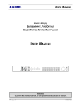
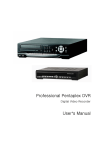
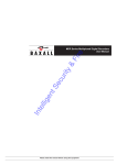
Contender Series DVR User Manual
Important Safeguards
WARNING
RISK OF ELECRIC SHOCK
DO NOT OPEN!
WARNING: TO REDUCE THE RISK OF ELECTRIC SHOCK,
DO NOT REMOVE COVER (OR BACK).
NO USER-SERVICEABLE PARTS INSIDE.
REFER SERVICING TO QUALIFIED
SERVICE PERSONNEL.
The lightning flash with arrowhead symbol, within an equilateral triangle, is intended to alert the user to the presence of
un-insulated “dangerous voltage” within the product’s enclosure that may be of sufficient magnitude to constitute a risk of
electric shock.
The exclamation point within an equilateral triangle is intended to alert the user to the presence of important operating and
maintenance (servicing) instructions in the literature accompanying the appliance.
COMPLIANCE NOTICE OF FCC:
THIS EQUIPMENT HAS BEEN TESTED AND FOUND TO COMPLY WITH THE LIMITS FOR A CLASS A DIGITAL
DEVICE, PURSUANT TO PART 15 OF THE FCC RULES. THESE LIMITS ARE DESIGNED TO PROVIDE
REASONABLE PROTECTION AGAINST HARMFUL INTERFERENCE WHEN THE EQUIPMENT IS OPERATED IN A
COMMERCIAL ENVIRONMENT. THIS EQUIPMENT GENERATES, USES, AND CAN RADIATE RADIO FREQUENCY
ENERGEY AND IF NOT INSTALLED AND USED IN ACCORDANCE WITH THE INSTRUCTION MANUAL, MAY
CAUSE HARMFUL INTERFERENCE TO RADIO COMMUNICATIONS. OPERATION OF THIS EQUIPMENT IN A
RESIDENTIAL AREA IS LIKELY TO CAUSE HARMFUL INTERFERENCE, IN WHICH CASE USERS WILL BE
REQUIRED TO CORRECT THE INTERFERENCE AT THEIR OWN EXPENSE.
CAUTION: CHANGES OR MODIFICATIONS NOT EXPRESSLY APPROVED BY THE PARTY RESPONSIBLE FOR
COMPLIANCE COULD VOID THE USER’S AUTHORITY TO OPERATE THE EQUIPMENT.
THIS CLASS OF DIGITAL APPARATUS MEETS ALL REQUIREMENTS OF THE CANADIAN INTERFERENCECAUSING EQUIPMENT REGULATIONS.
The information in this manual is believed to be accurate as of the date of publication. The
information contained herein is subject to change without notice. Revisions or new editions
to this publication may be issued to incorporate such changes.
6701 CLINTON ROAD • LOVES PARK, IL 61111 • 1-800-549-6393 (SUPPORT) • www.clintonelectronics.com
1
Contender Series DVR User Manual
Important Safeguards
1. Read Instructions
All the safety and operating instructions should be read before the
appliance is operated.
2. Retain Instructions
The safety and operating instructions should be retained for future
reference.
3. Cleaning
Unplug this equipment from the wall outlet before cleaning it. Do not
Use liquid aerosol cleaners. Use a damp soft cloth for cleaning.
4. Attachments
Never add any attachments and/or equipment without the approval of
The manufacturer as such additions may result in the risk of fire,
electric shock or other personal injury.
5. Water and/or Moisture
Do not use this equipment near water or in contact with water.
6. Accessories
Do not place this equipment on an unstable cart, stand or table. The
equipment may fall, causing serious injury to a child or adult, and
serious damage to the equipment. Wall or shelf mounting should
follow the manufacturer’s instructions, and should use a mounting kit
approved by the manufacturer.
7. Power Sources
This equipment should be operated only from the type of power source
Indicated on the marking label. If you are not sure of the type of power,
please consult your equipment dealer or local power company.
8. Power Cords
Operator or installer must remove power and TNT connections before
handling the equipment.
9. Lightning
For added protection for this equipment during a lightning storm, or
when it is left unattended and unused for long periods of time, unplug it
from the wall outlet and disconnect the antenna or cable system. This
will prevent damage to the equipment due to lightning and power-line
surges.
10. Overloading
Do not overload wall outlets and extension cords as this can result in
the risk of fire or electric shock.
11. Objects and Liquids
Never push objects of any kind through openings of this equipment as
They may touch dangerous voltage points or short out parts that could
Result in a fire or electric shock. Never spill liquid of any kind on the
Equipment.
12. Servicing
Do not attempt to service this equipment yourself. Refer all servicing
to qualified service personnel.
13. Damage requiring Service
Unplug this equipment from the wall outlet and refer servicing to
qualified service personnel under the following conditions:
A. When the power-supply cord or the plug has been damaged.
B. If liquid is spilled, or objects have fallen into the equipment.
C. If the equipment has been exposed to rain or water.
D. If the equipment does not operate normally by following the
operating instructions, adjust only those controls that are covered by
the operating instructions as an improper adjustment of other
controls may result in damage and will often require extensive work
by a qualified technician to restore the equipment to its normal
operation.
E. If the equipment has been dropped, or the cabinet damaged.
F. When the equipment exhibits a distinct change in performance —
this indicates a need for service.
14. Replacement Parts
When replacement parts are required, be sure the service technician has
used replacement parts specified by the manufacturer or that have the
same characteristics as the original part. Unauthorized substitutions
may result in fire, electric shock or other hazards.
15. Safety Check
Upon completion of any service or repairs to this equipment, ask the
service technician to perform safety checks to determine that the
equipment is in proper operating condition.
16. Field Installation
This installation should be made by a qualified service person and
should conform to all local codes.
17. Correct Batteries
Warning: Risk of explosion if battery is replaced by an incorrect type.
Dispose of used batteries according to the instructions.
18. Tmra
A manufacturer’s maximum recommended ambient temperature
(Tmra) for the equipment must be specified so that the customer and
installer may determine a suitable maximum operating environment
for the equipment.
19. Elevated Operating Ambient Temperature
If installed in a closed or multi-unit rack assembly, the operating
ambient temperature of the rack environment may be greater than room
ambient. Therefore, consideration should be given to installing the
equipment in an environment compatible with the manufacturer’s
maximum rated ambient temperature (Tmra).
20. Reduced Air Flow
Installation of the equipment in the rack should be such that the amount
of airflow required for safe operation of the equipment is not
compromised.
21. Mechanical Loading
Mounting of the equipment in the rack should be such that a hazardous
condition is not caused by uneven mechanical loading.
22. Circuit Overloading
Consideration should be given to connection of the equipment to
supply circuit and the effect that overloading of circuits might have on
over current protection and supply wiring. Appropriate consideration
of equipment nameplate ratings should be used when addressing this
concern.
23. Reliable Earthing (Grounding)
Reliable grounding of rack mounted equipment should be maintained.
Particular attention should be given to supply connections other than
direct connections to the branch circuit (e.g., use of power strips).
6701 CLINTON ROAD • LOVES PARK, IL 61111 • 1-800-549-6393 (SUPPORT) • www.clintonelectronics.com
2
Contender Series DVR User Manual
Table of Contents
Chapter 1 – Installation
1.1 Connecting the Video Source
1.2 Connecting the Loop Through Video
1.3 Connecting the Monitor
1.4 Connecting the Alarms
1.5 Connecting to the Network Port
1.6 Connecting Audio
1.7 Connecting to the USB Port
1.8 Connecting to a PTZ Camera
Chapter 2 – DVR Layout
2.1 Front Panel
2.2 Remote
2.3 Front Panel and Remote Explained
Chapter 3 – Initial Setup (System Menu)
3.1 Powering up the DVR for the First Time
3.2 Admin Password
3.3 General Setup
3.4 Alarm Type
3.5 HDD Setup
3.6 Monitor Setup
3.7 Password
3.8 Configuration
3.9 Shutdown
Chapter 4 – Camera Menu
4.1 Camera Setup
4.2 Adjustment
4.3 PTZ Setup
4.4 Spot Setup
4.5 Sequence
Chapter 5 – Record
5.1 Schedule Setup
5.2 Time Record Setup
5.3 Event Setup
5.4 Audio Record Setup
Chapter 6 – Network
6.1 Ethernet Setup
6.2 Serial Setup
6.3 DDNS Setup
6.4 Client Setup
6.5 E-Mail Setup
6.6 E-Mail Server Setup
Chapter 7 – Information
7.1 Status
7.2 Version
7.3 System Log
Chapter 8 – Operation
8.1 Login / Logout
8.2 Live Monitoring
8.3 Recording Video and Audio
8.4 Playing Video
8.5 Searching Video
8.6 Playing Video
8.7 Copy Video Clip
8.8 Backup Video Data
8.9 Print Image Frame
6701 CLINTON ROAD • LOVES PARK, IL 61111 • 1-800-549-6393 (SUPPORT) • www.clintonelectronics.com
3
Contender Series DVR User Manual
Chapter 1 – Installation
1.1 Connecting the Video Source
Figure 1 — Video input connectors.
Connect the coaxial cables from the video sources to the BNC Video In connectors.
1.2 Connecting the Loop Through Video
Figure 2 — Video Loop Through connectors.
If you would like to connect your video source to another device, you can use the Loop BNC connectors.
NOTE: The Loop BNC connectors are auto terminated. Do NOT connect a cable to the Loop BNC unless it
is connected to another terminated device because it will cause poor quality video.
1.3 Connecting the Monitor
Figure 3 — Video Out connectors.
Connect the monitor to Main, VGA, or S-Video connector.
Connect the spot monitor to the SPOT connector if required.
1.4 Connecting Alarms
Figure 4 — Alarm Input connector strips.
NOTE: To make connections on the Alarm Connector Strip, press and hold the button and insert the wire
in the hole above the button. After releasing the button, tug gently on the wire to make certain it is
connected. To disconnect a wire, press and hold the button below the wire and pull out the wire.
6701 CLINTON ROAD • LOVES PARK, IL 61111 • 1-800-549-6393 (SUPPORT) • www.clintonelectronics.com
4
Contender Series DVR User Manual
1.4 Connecting Alarms (continued)
You can use external devices to signal the DVR to react to events.
Mechanical or electrical switches can be wired to the AI (Alarm In) and GND (Ground) connectors. The threshold
voltage is 4.3V and should be stable at least 0.5 seconds to be detected. See 3.4 Alarm Type for configuring
alarm input.
NOTE: All the connectors marked GND are common.
Connect the ground side of the Alarm input and/or alarm output to the GND connector.
Figure 6 — Alarm Output connector strips.
The DVR can activate external devices such as buzzers or lights. Connect the device to the AO (Alarm Out) and
GND (Ground) connectors. See 3.4 Alarm Type for configuring alarm output.
1.5 Connecting to the Network Port
Figure 5 — Network connector.
The DVR can be networked using the 10/100Mb Ethernet connector. Connect a Cat5 cable with an RJ-45 jack to
the DVR connector. The DVR can be networked with a computer for remote monitoring, searching, configuration
and software upgrades. See 6.1 Ethernet for configuring the Ethernet connections.
1.6 Connecting Audio
NOTE: It is the user’s responsibility to determine if local laws and regulations permit recording audio.
Figure 6 — Audio In and Out connectors.
6701 CLINTON ROAD • LOVES PARK, IL 61111 • 1-800-549-6393 (SUPPORT) • www.clintonelectronics.com
5
Contender Series DVR User Manual
1.6 Connecting Audio (continued)
Your DVR can record audio. Connect the audio source to Audio In. Connect Audio Out to your amplifier.
NOTE: The DVR does not have amplified audio output, so you will need a speaker with an amplifier. The
audio input can be from an amplified source or directly from a microphone.
1.7 Connecting to the USB Port
Figure 7 — USB connectors.
A USB port is provided to connect external hard disk drives or USB memory sticks for clip copying video.
1.8 Connecting to a PTZ Camera
Make a connection of PTZ unit to RS485 at the rear panel of DVR. PTZ units currently being supported are
Clinton, Pelco-D/P, NVCC-Z42N, CyberDome (Kalatel), Samung, Samsung Techwin, Sungjin, Dongyang, DRX500, Fastrax II, Sensormatic, PIH-7600, Eyeview dome.
Figure 8 — DVR back panel.
6701 CLINTON ROAD • LOVES PARK, IL 61111 • 1-800-549-6393 (SUPPORT) • www.clintonelectronics.com
6
Contender Series DVR User Manual
Chapter 2 – DVR Layout
2.1 Front Panel
2.2 Remote
6701 CLINTON ROAD • LOVES PARK, IL 61111 • 1-800-549-6393 (SUPPORT) • www.clintonelectronics.com
7
Contender Series DVR User Manual
2.3 Front Panel and Remote Explained
1. CD-RW: Insert CD-RW to backup video.
2. USB Ports: Insert Flash Drive to backup video.
3. IR Remote Sensor: IR sensor for handheld remote
4. LED Indicators: Power, Fan, CD-RW, Record, Network
5. Function Buttons:
DISPLAY: Toggles between different display formats.
REC: When pressing the REC button in the live mode your DVR will start recording.
MENU: Enters setup screen. Pressing the button also closes the current menu or setup dialog box.
ESC: Exits the menu screens or moves to the upper menu.
ROTATE: Displays another screen.
BACKUP: Pressing the BACKUP button 3 times will display the Backup menu. Pressing again will exit
backup menu.
SEARCH: Displays the Search menu. Pressing again will exit Search menu.
PAUSE: Pressing the PAUSE button while in live mode will freeze all live camera images.
Pressing the PAUSE button while in the playback mode will pause the video of selected cameras.
6. Numeric Keypad (0-9, +10): Pressing the individual numbered buttons will cause the corresponding
camera to display full screen. These buttons are also used for entering user passwords. Use the +10
button to select numbers larger than 10. (For example: +10 + 6 = 16)
Log Out: Pressing the LOG OUT button locks all menu screens. You must re-enter the administrator
password to access the setup menus.
7. Fast Rewind: Pressing the FAST REWIND button while in search mode plays video backward at a
high speed. Pressing button again increases speed.
8. Arrow Buttons: These buttons navigate through menus. They are also used to control a PTZ when
in PTZ mode. The arrows can be used to move the position of the active camera selection screen.
These buttons also have the following functions in the Playback mode:
UP: Panorama playback by the hour and frame by frame.
DOWN: Time jump playback (Smart Search).
LEFT: Backward playback at regular speed.
RIGHT: Forward playback at regular speed.
9.
Fast Forward: Pressing the FAST FORWARD button while in search mode plays video forward at a
high speed. Pressing button again increases speed.
10. ID Button: Press and hold then enter the DVR ID number you want to select. (For example: To select
DVR ID # 3 – Press and hold ID button then enter 0 + 3, the LED will go to solid to confirm. You must
enter 0 then the number for ID numbers 0-9. (Note you must change each DVR ID - see Unit ID in
section 3.3)
6701 CLINTON ROAD • LOVES PARK, IL 61111 • 1-800-549-6393 (SUPPORT) • www.clintonelectronics.com
8
Contender Series DVR User Manual
Chapter 3 – Initial Setup (System Menu)
3.1 Powering up the DVR for the First Time
Complete the steps in Chapter 1- Installation before continuing.
Once the DVR is installed properly: Turn on the DVR by pressing the rocker switch located on the back of the
DVR.
Upon power-up the DVR will begin initialization, which will take approximately 60 seconds. As soon as the DVR
completes its initialization process, it will begin showing live video on the attached monitor and playing live audio
through the attached speaker. The default mode is to display all cameras at once. Pressing any camera button
will cause that camera to display full screen. It displays live video and plays live audio until the user enters
another mode.
Before using your DVR for the first time, you will need to establish the initial settings. Your DVR can be set up
using the System Menu.
3.2 Admin Password
Press the MENU button to enter the setup screens. The Admin Password screen appears.
Figure 9 — Admin password.
Enter the password by pressing the appropriate combination of number buttons and then the ENTER button. The
factory default password is 1111.
3.3 General Setup
Select the GENERAL SETUP in the main menu – press ENTER.
Scroll through the menu using the UP and DOWN buttons on the DVR or Remote.
To change a menu item highlight the item and press the ENTER button.
Make sure that you select SAVE when done or all changes will be lost.
Figure 10 – General Setup.
3.3 General Setup (continued)
6701 CLINTON ROAD • LOVES PARK, IL 61111 • 1-800-549-6393 (SUPPORT) • www.clintonelectronics.com
9
Contender Series DVR User Manual
From the GENERAL SETUP screen you can change the following:
Language: Select your desired language from the list.
Date/Time: Turns Date/Time ON or OFF (When turning off the DATE/TIME display, your DVR will not display the
date and time information on the screen.)
Date Format: Select between: MM-DD-YYYY, DD-MM-YYYY, or YYYY-MM-DD
Date: Set date using either the number or the UP & DOWN buttons on DVR or Remote.
Time: Set time using either the number or the UP & DOWN buttons on DVR or Remote.
Time Zone: If your region recognizes DST (Daylight Savings Time) press ENTER and select your time zone from
the list.
Use DST: If your region does not recognize DST leave DST OFF. If your region does recognize DST turn DST
ON. (You must be connected to LAN to use this function)
Buzzer: Turn ON or OFF “beep” sound.
Unit ID: To use one remote for multiple DVRs first you must change each DVR ID number:
Select Unit ID – press ENTER.
Set a different UNIT ID for each DVR (0-19).
Select ok - press ENTER
Select save - press ENTER.
The DVR is now set for that UNIT ID.
Now you can use the remote to select that particular DVR ID by:
Holding the ID button (#10) down.
Enter the DVR ID number using the remote keypad (#4). (You must enter “0” then the number for IDs 0-9)
Release the ID button.
The remote controller is now set for that DVR.
Menu Style: Choose from BASIC or PLUS. Default menu style is PLUS. You can set up the DVR using the
BASIC menu style however some features will be missing. To set in detail you have to change the menu style to
PLUS again.
3.4 Alarm Type
Select the ALARM TYPE in the main menu and press the ENTER button. The ALARM TYPE screen displays the
alarm inputs and outputs. Change TYPE from the ALARM IN to the ALARM OUT button by highlighting it and
pressing the ENTER button.
Select the proper alarm type between NO (Normally Open) and NC (Normally Close) by highlighting the box
below TYPE and pressing the ENTER button.
Save changes and return to the main menu by highlighting SAVE and pressing the ENTER button. Selecting
CANCEL exits the screen without saving the changes.
6701 CLINTON ROAD • LOVES PARK, IL 61111 • 1-800-549-6393 (SUPPORT) • www.clintonelectronics.com
10
Contender Series DVR User Manual
3.5 HDD Setup
Select the HDD SETUP in the main menu and press the ENTER button. The HDD SETUP screen will display
three pages, INSTALL, OVERWRITE, CHECK, and SMART.
NOTE: The INSTALL, CHECK, and SMART setup screens are for factory use. Tampering with these
settings may cause your DVR to not perform correctly.
Select the second page, HDD SETUP – OVERWRITE and the following screen will appear.
Figure 12 – HDD Setup – Overwrite.
You can turn ON or OFF the overwriting option by selecting the box beside HDD OVERWRITE.
NOTE: When turning off the overwriting, your DVR will stop recording when the disk is full.
When turning off the overwriting, the boxes beside REMAIN TIME and USED SPACE will be activated.
You can set up the HDD usage by changing the REMAIN TIME and USED SPACE.
NOTE: When setting up the USED SPACE to 80%, your DVR will stop recording at 80%. Your DVR will
check the settings of REMAIN TIME and USED SPACE automatically and record as long as possible.
Your DVR has 3 different warning methods when the disk is full but the DISK FULL WARNING must be turned on
in the WARNING CONDITION menu.
You can assign an alarm out by selecting the box beside DISK FULL ALARM and turn on the buzzer or OSD
warning message.
3.6 Monitor Setup
Select MONITOR SETUP in the main menu and press the ENTER button.
6701 CLINTON ROAD • LOVES PARK, IL 61111 • 1-800-549-6393 (SUPPORT) • www.clintonelectronics.com
11
Contender Series DVR User Manual
Figure 14 – Monitor Setup.
3.6 Monitor Setup (continued)
Video Format: Select AUTO or choose either NTSC (North American Standard) or PAL (European Standard).
Border Color: Select from Black, White, or Grey as the desired border color.
Alpha Blending: You can adjust the transparency of the menu screen by highlighting the box beside ALPHA
BLENDING and pressing the ENTER button.
Menu Time Out: You can set up the menu time-out duration up to 10 minutes by highlighting the box beside
MENU TIME OUT and pressing the ENTER button. Use the ARROW buttons to adjust the slide bar.
VGA Resolution: Select your VGA monitor’s resolution. (You must enter your password to access this item)
Screen Position: You can change the screen position by highlighting the desired directional arrow and press
ENTER.
VGA Adjustment: Highlight VGA ADJUSTMENT and press the ENTER button.
The ADJUSTMENT screen displays the brightness, contrast, and saturation.
Highlight values beside BRIGHT, CONTRAST or SATURATION and press the ENTER button.
Use the ARROW buttons to slide the bar to the desired setting.
Highlight the SAVE button and press the ENTER button to save your changes in the sub-menu.
OSD Color: You can change the color of the MENU and LIVE OSD.
Select the color you would like to change and enter a new RGB value using the ARROW buttons or enter the
desired value using the NUMBER buttons
3.7 Password
An Administrator password is required to turn the system off, enter the setup screen, load default setups, clear all
data, change system date and time and change the Administrator password. Highlight PASSWORD in the Main
menu and press to enter the Password screen.
3.7 Password (continued)
6701 CLINTON ROAD • LOVES PARK, IL 61111 • 1-800-549-6393 (SUPPORT) • www.clintonelectronics.com
12
Contender Series DVR User Manual
Figure 15 — Password Setup.
The PASSWORD SETUP screen displays three different user authorizations, ADMIN, Superuser and User.
Superuser can use all functions but can’t access the Menu to change the settings. The User can use PTZ and
Status only. Highlight the ADD or DEL buttons and press the ENTER button to add or delete each user. When
adding a new user account, you will be asked to enter the new password and to confirm it. When deleting a user
account, you will be asked to confirm.
NOTE: The default Admin password is: 1111.
CAUTION: Don’t delete the default Admin account, root before adding a new account. If deleting the
default Admin, root before adding at least one Admin account, you can’t reach to Menu to set up the
system.
3.8 Configuration (password required)
You can save configurations to DVR system and load from DVR system. Highlight the CONFIG in the main menu
and press the ENTER button. The following screen will appear.
Figure 16 – Config (1).
Figure 17 – Config (2).
Select SAVE and press the ENTER button. The virtual keyboard will appear and you can type the title and you
can select the configurations for Camera, Record, System and Network. Press the ENTER button after selecting
the configurations that you want to save. You can also load the saved configurations to the DVR system.
NOTE: The DEFAULT is the factory default.
Upgrade: You can upgrade the DVR software by using USB memory or CD.
•
•
•
Connect USB memory to DVR or insert CD.
Highlight UPGRADE and press the ENTER button.
Upgrade performs automatically.
3.9 Shutdown
6701 CLINTON ROAD • LOVES PARK, IL 61111 • 1-800-549-6393 (SUPPORT) • www.clintonelectronics.com
13
Contender Series DVR User Manual
You can shutdown your DVR by highlight the SHUTDOWN in the SYSTEM menu and pressing
the ENTER button.
When you highlight the SHUTDOWN and press the ENTER button. You have to input the Admin Password to
confirm identification.
Highlight OK and press the ENTER button.
NOTE: To turn off the DVR, you have to power down after SHUTDOWN. The DVR power switch is at the
back of the DVR.
6701 CLINTON ROAD • LOVES PARK, IL 61111 • 1-800-549-6393 (SUPPORT) • www.clintonelectronics.com
14
Contender Series DVR User Manual
Chapter 4 – Camera Menu
The camera Menu is used for general camera settings, camera image color, location control, or PTZ camera
settings.
4.1 Camera Setup
Highlight CAMERA SETUP in the main menu and press the ENTER button. The SETUP screen appears.
Figure 18 – Camera Setup.
The SETUP screen displays the camera label and the camera inputs.
You can turn on or off the camera number and camera name by highlighting the box beside CAMERA LABEL and
pressing the ENTER button. Select one of the ALL, NAME, NUMBER, or OFF.
You can assign names to each camera by highlighting the boxes below NAME and pressing the ENTER button. A
virtual keyboard allows you to enter camera names.
NOTE: When selecting the OFF, the DVR doesn’t display the camera number and name.
You can connect or disconnect the video input by highlighting the boxes below POWER and pressing
the ENTER button.
NOTE: The ENTER button allows you to select ON or OFF.
NOTE: When selecting the OFF, the DVR disconnects the video source so the camera can’t be displayed
and recorded.
You can hide or display the video of the camera by highlighting the boxes below HIDDEN heading and pressing
the ENTER button. Select ON or OFF by pressing the ENTER button.
You can save your changes by highlighting SAVE and pressing the ENTER button. Selecting CANCEL exits the
screen without saving the changes.
6701 CLINTON ROAD • LOVES PARK, IL 61111 • 1-800-549-6393 (SUPPORT) • www.clintonelectronics.com
15
Contender Series DVR User Manual
4.2 Adjustment
Highlight ADJUSTMENT in the main menu and press the ENTER button. The ADJUSTMENT screen appears.
Figure 19 – Adjustment.
The ADJUSTMENT screen displays the brightness, contrast, saturation, hue, and position.
You can select the channel by highlighting the box right CAMERA and pressing the ENTER button.
You can select the live or recorded video by highlighting the box below LIVE and pressing the ENTER button.
You can adjust the brightness, contrast, saturation, and hue by highlighting the headings.
You can change the position of the screen by highlighting the arrow buttons of the POSITION and pressing the
ENTER button.
You can apply your adjustments to all the channels by using the APPLY ALL button.
NOTE: Highlight the SAVE button and press the ENTER button to save your changes in the sub-menu.
4.3 PTZ Setup
Highlight PTZ SETUP in the main menu and press the ENTER button. The PTZ SETUP screen appears.
Figure 20 – PTZ Setup (1).
Figure 21 – PTZ Setup (2).
You can set up the baud rate, data bit, parity, and stop bit by highlighting the boxes below PORT and pressing the
ENTER button.
6701 CLINTON ROAD • LOVES PARK, IL 61111 • 1-800-549-6393 (SUPPORT) • www.clintonelectronics.com
16
Contender Series DVR User Manual
4.3 PTZ Setup (continued)
You can set up IDs for each channel on the ID heading by highlighting the boxes below ID and pressing
the ENTER button.
You can set up PTZ camera type by highlighting the boxes below TYPE and press the ENTER button.
Select your camera from the list and press the ENTER button
You will need to connect the camera to the RS485 terminal on the back of the DVR following the camera
manufacturer’s instructions.
4.4 Spot Setup
Your DVR can set up 3 spot monitors. Highlight the SPOT SETUP in the main menu and press
the ENTER button. The following SPOT SETUP screen will appear.
Figure 22 – Spot Setup.
You can turn on or off the SEQUENCE for cameras for spot. Turn on or off the SEQUENCE by highlighting the
ON or OFF below SEQUENCE and pressing the ENTER button.
You can set up the rotating dwell time by highlighting the box below INTERVAL and pressing the ENTER button.
It can be set up to 256 seconds.
4.5 Sequence
You can set up the dwell time and the sequence for rotation. Select the SEQUENCE in the main menu and press
the ENTER button. The following screen will appear.
Figure 23 – Sequence.
6701 CLINTON ROAD • LOVES PARK, IL 61111 • 1-800-549-6393 (SUPPORT) • www.clintonelectronics.com
17
Contender Series DVR User Manual
Chapter 5 – Record Menu
Configuring Recording Settings
Your DVR offers a variety of flexible recording modes. You can set it up to record all the time or to only record
events. It can be set up to continue recording once the hard disk drive is full by recording over the oldest video, or
you can set it up alert you when the hard disk is full and stop recording.
5.1 Schedule Setup
Highlight SCHEDULE SETUP in the main menu and press the ENTER button. The SCHEDULE SETUP screen
appears.
Figure 24 – Schedule Setup.
Figure 25 – Schedule Setup – Resolution.
You can set up daytime period by highlighting the boxes beside DAY and pressing the ENTER button.
NOTE: The night time period is changed automatically, according to the setting of the daytime.
You can set up weekend and add or delete holidays in the HOLIDAY SETUP menu by highlighting
the ARROW icon in the HOLIDAY heading and pressing the ENTER button.
You can select the resolution between standard resolution and high resolution by highlighting the box beside
RESOLUTION and pressing the ENTER button.
If you want to change the resolution of certain cameras, press the ARROW icon button in the RESOLUTION
heading.
CAUTION: Your changes in the SETUP screens are applied to every channel, days and other items. If you
want to change certain details, enter to the sub-menu by highlighting the ARROW icon button and
pressing the ENTER button.
6701 CLINTON ROAD • LOVES PARK, IL 61111 • 1-800-549-6393 (SUPPORT) • www.clintonelectronics.com
18
Contender Series DVR User Manual
5.2 Time Record Setup
Highlight TIME RECORD SETUP in the main menu and press the ENTER button. The TIME RECORD SETUP
screen appears.
Figure 26 – Time Record Setup.
Figure 27 – Time Record Setup (Speed & Quality).
Highlight the RECORD heading on DAY, NIGHT, or WEEKEND and press the ENTER button to toggle between
ON and OFF.
You can set up the recording speed and select the recording quality between LOW, NORMAL, HIGH, &
HIGHEST.
NOTE: To select the recording speed, use the ENTER button.
You can change the certain details by highlighting the DETAIL button (ARROW icon) and pressing the ENTER
button.
5.3 Event Setup
Highlight EVENT SETUP in the main menu and press the ENTER button. The EVENT SETUP screen appears.
The DVR can be set to react to events differently. Each sensor can be assigned to a camera, recording speed,
video quality, and dwell time.
Figure 28 – Event Record Setup.
Highlight the INPUT, MOTION or VIDEO LOSS in the EVENT INPUT menu and press the ENTER button to
toggle between ON and OFF.
NOTE: When turning off the input, you can’t select event inputs, MOTION, ALARM IN or VIDEO LOSS.
6701 CLINTON ROAD • LOVES PARK, IL 61111 • 1-800-549-6393 (SUPPORT) • www.clintonelectronics.com
19
Contender Series DVR User Manual
5.3 Event Setup (continued)
Highlight the ARROW icon in the EVENT INPUT menu to change the motion detection area for each camera, or
change details for certain cameras. The following EVENT SETUP – INPUT screen will appear.
Figure 29 – Event Setup - Input.
NOTE: Highlight and press the ARROW icon beside of the EVENT to access MOTION, VIDEO LOSS and
ALARM IN.
You can set up the motion event ON/OFF and sensitivity of each camera in the MOTION menu.
Highlight the MOTION beside of the EVENT and press the ENTER button to set up the alarm input.
The following ALARM IN screen will appear.
Figure 30 – Event Setup – Input – Alarm In.
You can select cameras that will be associated with the each alarm.
When the Record in EVENT OUTPUT menu is ON state, the video of associated camera will be recorded when
alarm input event is occurred.
6701 CLINTON ROAD • LOVES PARK, IL 61111 • 1-800-549-6393 (SUPPORT) • www.clintonelectronics.com
20
Contender Series DVR User Manual
5.3 Event Setup (continued)
Highlight the ALARM IN beside of the EVENT and press the ENTER button to set up the VIDEO LOSS.
The following VIDEO LOSS screen will appear.
Figure 31 – Event Setup – Input – Video Loss.
You can select cameras that will be associated with the video loss.
To set up EVENT RECORD, highlight the INPUT beside EVENT SETUP on EVENT RECORD SETUP menu and
press the ENTER button. The EVENT RECORD SETUP menu will be changed as below window. Select the
RECORD ON/OFF, SPEED, QUALITY, or POST RECORDING dwell time.
Figure 32 – Event Record Setup
NOTE: The speed in the EVENT OUTPUT menu will be associated with the resolution setting in the
SCHEDULE SETUP menu. When selecting the STD resolution in the SCHEDULE SETUP menu, the
maximum speed will be 30fps. In case of selecting HIGH resolution, the maximum speed will be 15fps.
You can select the quality by toggling between LOW, NORMAL, HIGH, & HIGHEST. This selection is not affecting
the recording frame per sec. When selecting Highest, it gives better image quality but the file size will be bigger
than LOW, NORMAL, & HIGH.
You can set up the Post Recording time up to 100 seconds by highlighting the below box and pressing
the ENTER button. Highlight the ARROW icon and pressing the ENTER button to change the details in the submenu.
6701 CLINTON ROAD • LOVES PARK, IL 61111 • 1-800-549-6393 (SUPPORT) • www.clintonelectronics.com
21
Contender Series DVR User Manual
5.3 Event Setup (continued)
Figure 33 – Event Setup - Record
Figure 34 – Event Setup – Record - Detail
You can turn ON or OFF recording, change the speed, and change the image quality for DAY, NIGHT, &
WEEKEND. You can change the settings for individual cameras in the sub-menu by highlighting the ARROW icon
and pressing the ENTER button.
To set up EVENT ACTION, Highlight the RECORD beside of the EVENT SETUP on EVENT RECORD SETUP
menu and press the ENTER button. The EVENT RECORD SETUP menu will be changed as below window.
Figure 35 – Event Setup.
You can set up event actions by toggling between ON and OFF for Action, Image, Alarm, and Preset. You can
also set up the popup screen dwell time by highlighting the DISPLAY button and press the ENTER button.
Highlight the ARROW icon and press the ENTER button to change certain details in the sub-menu. The following
EVENT SETUP-ACTION screen appears.
Figure 36 – Event Setup - Action.
6701 CLINTON ROAD • LOVES PARK, IL 61111 • 1-800-549-6393 (SUPPORT) • www.clintonelectronics.com
22
Contender Series DVR User Manual
5.3 Event Setup (continued)
You can associate the ALARM OUT, DELAY and DURATION for each camera by highlighting the action type
beside of the EVENT and pressing the ENTER button and toggle ON or OFF.
NOTE: To associate the preset for each camera, PRESET must be set in PTZ menu
5.4 Audio Record Setup
Highlight the AUDIO RECORD SETUP in the main menu and press the ENTER button. The AUDIO RECORD
SETUP screen appears.
Figure 37 – Audio Record Setup.
You can turn ON or OFF the audio recording by highlighting the boxes beside DAY, NIGHT, WEEKEND, LIVE, or
PLAYBACK by pressing the ENTER button.
You can also set up the volume by highlighting and pressing the ENTER button.
6701 CLINTON ROAD • LOVES PARK, IL 61111 • 1-800-549-6393 (SUPPORT) • www.clintonelectronics.com
23
Contender Series DVR User Manual
Chapter 6 – Network
Configuring Network Settings
Control communication related setting from DVR. It not only sets for commonly using Ethernet, but also monitors
the status of server from a remote site through the Client and E-mail setting.
6.1 Ethernet Setup
You can turn ON or OFF the dynamic IP by highlighting the box beside the DYNAMIC IP and pressing
the ENTER button.
Figure 38 – Ethernet Setup.
When turning off the Dynamic IP, you can enter the static IP information.
You can set HOST name using the virtual keyboard.
You can set IP ADDRESS, SUBNET MASK, GATEWAY and DNS using the UP, DOWN, LEFT, & RIGHT
buttons or number buttons on DVR or remote.
6.2 DDNS Setup
Highlight the DDNS SETUP in the main menu and press the ENTER button. The following DDNS SETUP screen
will appear.
Figure 61 – DDNS SETUP
Figure 39 – DDNS Setup.
6701 CLINTON ROAD • LOVES PARK, IL 61111 • 1-800-549-6393 (SUPPORT) • www.clintonelectronics.com
24
Contender Series DVR User Manual
6.2 DDNS Setup (continued)
Select the DDNS server. Your DVR already has been registered.
Input ID, PASSWORD and HOST NAME have been registered on the DDNS server using the virtual keyboard.
If you use PUBLIC IP, set the PUBLIC IP ON, if not, OFF.
If the connecting to DDNS server is not good, you can check the status of connecting to DDNS server by pressing
the CHECK beside of STATUS.
6.3 Client Setup
Highlight the CLIENT SETUP in the main menu and press the ENTER button. The following CLIENT SETUP –
CLIENT screen will appear.
Figure 40 – Client Setup - Client.
•
•
•
Figure 41 – Client setup – User.
Enter the SMS Port for SMS client connection. The default TCP port is 7000.
Enter the WEB Port for WEB client connection. The default TCP port is 80.
You can select to use the remote configuration by highlighting the boxes beside and press the ENTER
button.
Change the setup title beside of the SETUP to USER to add or delete accounts.
You can create new accounts by highlighting ADD button and pressing the ENTER button. Type the new account
by using the virtual keyboard. When saving a new account, the password screen will appear. Type the password
for the new account. The confirm screen will appear. Retype the password.
Change the setup title beside of the SETUP to ACCESS to define the IP access range from the client.
Figure 42 – Client Setup - Access.
6701 CLINTON ROAD • LOVES PARK, IL 61111 • 1-800-549-6393 (SUPPORT) • www.clintonelectronics.com
25
Contender Series DVR User Manual
6.3 Client Setup (continued)
When you change from ALL to RANGE, an IP address of client that is not in the access range can’t access to the
server the default range is ALL.
6.4 Email Setup
Your DVR can notify any event to assigned e-mail addresses and you can assign e-mail addresses up to 6.
Highlight the E-MAIL SETUP in the main menu and press the ENTER button. The following E-MAIL
NOTIFICATION screen will appear.
Figure 43 – E-Mail Setup (1).
Figure 44 – E-Mail Setup (2).
You can associate events for the e-mail notification. Highlight the box below SEND and press the ENTER button.
Then the event list will appear. If selected event is occurred, email will be sent to associate email address.
If the SCHEDULE is ON, the e-mail is available within setting time.
And, if the SCHEDULE is OFF, the e-mail is available always.
You can choose if the captured picture is attached or not by choice of ON/OFF under the PIC.
You can type the e-mail addresses you want to assign by using the virtual keyboard.
6701 CLINTON ROAD • LOVES PARK, IL 61111 • 1-800-549-6393 (SUPPORT) • www.clintonelectronics.com
26
Contender Series DVR User Manual
Chapter 7 – Information
7.1 Status
You can check the status of the DVR by pressing the STATUS button. The Status screen displays Recording,
Event and Audio status and Disk and Key information.
Figure 45 – Status.
7.2 Version
You can check the version of your DVR in the VERSION menu. Refer to the below screen. The VERSION screen
will display the version information.
Figure 46 – Version.
7.3 System Log
You can check the system log by selecting the SYSTEM LOG in the main menu. The below screen will appear.
You can move to the previous page or next pages by pressing PREV or NEXT button in the SYSTEM LOG menu.
Figure 47 – System Log.
6701 CLINTON ROAD • LOVES PARK, IL 61111 • 1-800-549-6393 (SUPPORT) • www.clintonelectronics.com
27
Contender Series DVR User Manual
Chapter 8 – Operation
NOTE: This chapter assumes your DVR has been installed and configured. If it has not, please refer to
Chapters 1 - 7.
8.1 Login / Logout
Login
This system classifies user category as ADMIN, SUPERUSER, or USER limiting the access to system operation.
Each login authority level and access level has been summarized as below, and ADMIN level overrides all.
Press the MENU button to enter the setup screens. The Admin Password screen appears.
Figure 48 — Admin Password.
Enter the password by pressing the appropriate combination of Camera number buttons and then the Enter
button. The factory default password is 1111.
The login window appears when the following buttons are pressed.
Button (Function)
MENU
SEARCH
BACKUP
PTZ
Log-in Authority
Admin
Superuser
Superuser
User
Logout
To log-out from the system click the LOCK button at front panel to brute force log-out.
The DVR system automatically does log-out after a certain time is elapsed. Menu Timeout that has been set to
System Setting is the time for predefined automatic log-out time.
Button
Function
Remarks
Lock
It locks DVR as Logout stage
6701 CLINTON ROAD • LOVES PARK, IL 61111 • 1-800-549-6393 (SUPPORT) • www.clintonelectronics.com
28
Contender Series DVR User Manual
8.2 Live Monitoring
The Front Panel Display and controls are described in 2.1 — Front Panel Layout.
Button (Function)
Remarks
By repeatedly pressing the button you can cycle through the 1, 4, 7, & 9
screen grid displays.
DISPLAY
ROTATE
Pressing the button allows automatic sequential screen split for 1, 4, 9 etc.
For example, press the button with 4-screen displays change into the next 4
different camera inputs automatically repeating the sequence.
FREEZE
Temporary stops the monitoring screen and press again to resume the
original screen mode.
(This button is also used to reset the USB module)
Enter
Numeric Key (0-9)
10+ Num. Key (10+)
Selecting Cameo or displaying Cameo menu
Used for selecting the corresponding camera.
Used for entering number greater than 10
Live Cameo Menu
When in live format, press the ENTER button and a green square cursor will appear. You can move the cursor by
using arrow buttons and press the ENTER button again to pop up the cameo menu.
Figure 49 – Live Cameo Menu.
LIVE HIDDEN ON/OFF: You can hide ON or OFF the live camera to the selected channel. Press the ENTER
button after highlighting the LIVE HIDDEN ON or LIVE HIDDEN OFF.
RECORD CHANGE: You can change the recording quality, resolution and recording speed to the selected
channel in this menu.
Figure 50 Cameo Record Changes.
6701 CLINTON ROAD • LOVES PARK, IL 61111 • 1-800-549-6393 (SUPPORT) • www.clintonelectronics.com
29
Contender Series DVR User Manual
Live Cameo Menu (continued)
SEQUENCE: When selecting the SEQUENCE on the above CAMEO menu, the following menu will show.
Figure 51 Cameo Sequence.
•
•
•
CAMEO SEQUENCE: just selected cameo is rotated with the other channels out of monitor.
GROUP SEQUENCE: all channels in monitor are rotated with the other channels out of monitor.
CANCEL SEQUENCE: stop cameo sequence or group sequence.
NOTE: you can set rotate frequency on SYSTEM MENU with PLUS MEMU TYPE
Playback Cameo Menu
When in one of playback formats, press the ENTER button and green square cursor will appear. When moving
the cursor to the bottom or top, the following pop-up menu will appear.
Figure 52 – Playback Cameo Menu.
Live and Playback Cameo Change
You can select a cameo camera and change the selected cameo viewer with live or playback channel that you
want to watch.
If you want to change the selected cameo to Live Viewer, highlight the LIVE CAM CHANGE and press the
ENTER button.
If you want to change the selected cameo to Playback Viewer, highlight the LIVE CAM CHANGE and press the
ENTER button.
Then, you can select channel you want to view using below slide menu.
Figure 53 – Camera Change Slide.
NOTE: If you change cameos using LIVE CAM CHANGE or PLAY CAM CHANGE, changed cameos are
preserved until you change cameos, and at next searching and playing also they are preserved.
So, to watch default playback cameos you have to highlight the DEFAULT on the upper slide menu and
press the ENTER button.
6701 CLINTON ROAD • LOVES PARK, IL 61111 • 1-800-549-6393 (SUPPORT) • www.clintonelectronics.com
30
Contender Series DVR User Manual
8.3 PTZ Control
The DVR will control cameras with Pan, Tilt, and Zoom capabilities. Press the PTZ button to enter the PTZ mode.
The Mark ‘P’ is printed on the Cameos PTZ camera is set. And the lowest channel is selected among the PTZ
Cameos.
NOTE: PTZ cameras have to already be set. Refer to 4.3 PTZ Setup.
NOTE: You have to select channel you want to control PTZ camera using numeric buttons.
Figure 54 – PTZ Mode View.
You can control the camera using front panel buttons. Press the Left and Right arrow buttons to pan left and right.
Press the Up and Down arrow buttons to tilt the camera up and down.
You can change PTZ mode using front panel buttons, PRESET, ZOOM, FOCUS and IRIS.
•
•
•
•
PRESET: PTZ camera is moved to preset location and you can view the location.
ZOOM: to zoom in or zoom out PTZ camera.
FOCUS: to set focus manually.
IRIS: to move iris in or iris out.
You can control the camera using front panel buttons or by setting up presets, tour, or Group.
Press the menu button on the front panel.
If you highlight the MOVE in the above menu and press the ENTER button, you can tilt the camera. Press the Left
and Right arrow buttons to pan left and right. Press the Up and Down arrow buttons to tilt the camera up and
down.
If you highlight the ZOOM in the above menu and press the ENTER button, you can zoom the camera.
Press the Fast Forward and Rewind button to zoom in and out.
If you highlight the FOCUS in the above menu and press the ENTER button, you can set focus of camera using
Left and Right arrow buttons.
6701 CLINTON ROAD • LOVES PARK, IL 61111 • 1-800-549-6393 (SUPPORT) • www.clintonelectronics.com
31
Contender Series DVR User Manual
8.3 PTZ Control (continued)
If you highlight the SET beside of AUTO FOCUS in the above menu and press the ENTER button, camera focus
will be set automatically.
You can toggle TOUR ON and TOUR OFF. If TOUR state is ON, camera will be moved along the already set
PRESET GROUP until TOUR OFF. The PRESET GROUP has to be already set.
PRESET Setup
Your DVR can save 64 presets. Follow the next steps to set up presets. Select the preset number and move the
camera by using the front panel buttons and select OK to save the preset location.
You can assign presets up to 6 to a preset group and set up the dwell time and speed. Select a preset number,
press the Time button and set up the dwell time. When pressing the TIME again, the button will change to Speed.
Press the Speed button and then you can set up the moving speed. Press the ADD button. After adding 6 presets
or less, press the Save button to save the preset group.
To run the preset group, turn on the Tour in the upper menu. Your PTZ camera will tour the assigned preset
group.
NOTE: The Time is the dwell time on a preset position.
NOTE: The preset recalls the preset location.
NOTE: The Group means the preset group.
NOTE: The Tour means the preset group tour.
8.4 Recording Video & Audio
Recording Video
Once you have installed the DVR it is ready to record.
The DVR will start recording when you press the REC button on the front keypad.
Recording Cameo Window
01:C1
Ch 1 Cameo Window
: Time Recording
: Motion Recording
: Alarm Recording
: Videoloss Recording
Button
REC
Function
Record
Remarks
Start and stop recording button for the current schedule setting
6701 CLINTON ROAD • LOVES PARK, IL 61111 • 1-800-549-6393 (SUPPORT) • www.clintonelectronics.com
32
Contender Series DVR User Manual
8.5 Searching Video
You can select the media by changing the device beside TARGET. You can playback the recorded video from
HDD (Hard Disk Drive), CD or USB.
There are five ways of searching the recorded data on DVR.
1
2
3
4
5
6
QUICK SEARCH: Search for the recorded video data by date/time.
EVENT SEARCH: Search for the event occurred by search date.
OVERLAPPED LIST: Search for the data with overlapped date.
GO TO LAST: Search for data, recorded up to 10 minutes before the current time.
GO TO FIRST: Search for data, recorded at the earliest time in the Target device.
GO TO JUMP: Jump by hour or minute - this menu is only present on playing recorded video.
QUICK SEARCH
Days with recorded video listed. You can highlight number of the day with recorded video and press
the ENTER button to select it.
A time bar will be displayed on the TIME SEARCH screen. You can use Left and Right arrow buttons to highlight
the time bar. Once the time bar is highlighted, you can select time by using the Left and Right arrow buttons.
After selecting hour, you can select the time by the three minutes by pressing the ENTER button.
To play the recorded video, highlight the PLAY and press the ENTER button.
EVENT SEARCH
Select the EVENT SEARCH in the SEARCH menu.
Figure 56 – Event Search.
The EVENT SEARCH screen will display changeable Date/Time, recorded information and channel selection.
You can change the date/time and select the channels that you want to search.
You can search the recorded video by Motion, Alarm In and Video Loss by turning on or off. Once have selected
the events and channels for searching, highlight the SEARCH and press the ENTER button.
You will have a recorded list with events that you can playback by selecting one of them on the list.
6701 CLINTON ROAD • LOVES PARK, IL 61111 • 1-800-549-6393 (SUPPORT) • www.clintonelectronics.com
33
Contender Series DVR User Manual
8.5 Searching Video (continued)
OVERAPPED LIST
You can have an overlapped list by selecting
OVERAPPED LIST in the SEARCH menu. You can
select one of the video files in the list and playback.
Your DVR will create the overlapped video list caused
by Date/Time changes or applying the DST
(Daylight Saving Time).
Figure 57 – Overlapped List.
GO TO JUMP
This function allows to jump into the desired time frame. It is possible to jump by hour or minute.
It is possible to perform the function on playing recorded video without PAUSE or STEP PLAYBACK.
8.6 Playing Video
Normal Playback
Standard video playback - supports forward/backward playback, playback speed, and pause.
Single Step Playback
Single step playbacks the screen display one frame at a time by pressing LEFT/RIGHT button during the pause
stage. If you press the button again, it returns to Normal Playback mode. Single Step playback is useful for the
viewing of specific video image in detail.
Smart Playback
Pressing the SMART button while in Normal Playback mode activates smart Playback.
Smart playback is a function that displays the Alarm In section after searching the video that has movement.
Forward/Backward playback is possible and pressing SMART button during the playback changes to Normal
Playback mode.
Pressing SMART button once again will resume the Smart Playback mode.
Panorama Playback
Pressing up direction key from a single screen playback mode changes to 4/9/16 screen panorama viewing
mode. When the single screen is displayed, the mode is changed to Normal Playback.
Panorama playback displays a single frame of the video into several screens frame by frame.
6701 CLINTON ROAD • LOVES PARK, IL 61111 • 1-800-549-6393 (SUPPORT) • www.clintonelectronics.com
34
Contender Series DVR User Manual
8.6 Playing Video (continued)
Normal Playback
Normal playback means a steady speed playback. Pressing PLAY button allows to display the video that has
been searched through Searching Video.
8.7 Copy Video Clip
This is the function that allows copying a part of video clip during play back into USB or other recording media.
There are two ways of using it with cameo menu and front keys.
Using the front keys on PLAYBACK
- Click the BACKUP key for starting time
- Section to copy is made, click the BACKUP key again
- After that, click the BACKUP key of front keys
Make a copy after confirming the user selected channel and time frame.
Select CD or USB for storage media from TARGET.
Select Estimate then WRITE.
DvrPlayer is copied into backup CD or USB device automatically.
Backup video can be played using DvrPlayer.
DvrPlayer : Single channel video player similar to Windows Media Player
6701 CLINTON ROAD • LOVES PARK, IL 61111 • 1-800-549-6393 (SUPPORT) • www.clintonelectronics.com
35
Contender Series DVR User Manual
8.8 Backup Video Data
BACKUP TO THE INTERNAL CD-RW
You can backup the recorded video to the built-in CD-RW. Press the BACKUP button on the front or remote. The
following Backup screen will appear. And you can select channel in sub menu on right fig. if you press the box
beside CHANNEL.
Figure 58 – BACKUP.
You can set up the Date/Time for backup and select the channels. Press the ESTIMATE button and your DVR will
calculate the data size and display beside the REQUIRED SPACE.
Press the WRITE button and your DVR will prepare the burning to a CD and the CD space is limited up to 650MB.
NOTE: When the data size is bigger than 650MB, you will be asked to put a new CD after burning the first
CD.
You will be asked to confirm to backup the data to a CD.
DvrPlayer is copied into backup CD or USB device.
Backup video can be played using DvrPlayer.
DvrPlayer: Single channel video player similar to Windows Media Player
8.9 Print Image Frame
•
Search video to the desired image frame that you want to print.
•
Select the channel and enter the full screen mode by entering the channel number on the front panel
or remote.
•
Press the PAUSE button at the desired image frame that you want to print.
•
Press the ENTER button twice.
•
Select “Save JPEG” and save to desired target device.
6701 CLINTON ROAD • LOVES PARK, IL 61111 • 1-800-549-6393 (SUPPORT) • www.clintonelectronics.com
36