1
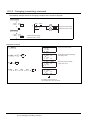
SAFETY PRECAUTIONS
(Always read these instructions before using this equipment.)
Before using this product, please read this manual and the relevant manuals introduced in this manual
carefully and pay full attention to safety to handle the product correctly.
The instructions given in this manual are concerned with this product. For the safety instructions of the
programmable controller system, please read the CPU module user's manual.
In this manual, the safety instructions are ranked as "DANGER" and "CAUTION".
DANGER
Indicates that incorrect handling may cause hazardous conditions,
resulting in death or severe injury.
CAUTION
Indicates that incorrect handling may cause hazardous conditions,
resulting in medium or slight personal injury or physical damage.
Note that the
CAUTION level may lead to a serious consequence according to the circumstances.
Always follow the instructions of both levels because they are important to personal safety.
Please save this manual to make it accessible when required and always forward it to the end user.
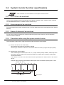
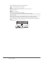
[PRECAUTION WHEN PERFORMING THE TEST OPERATION]
CAUTION
Read the manual carefully and fully understand the operation before the test operation (ON/OFF)
of bit devices, modifying current value of a word device, modifying timer/counter setting,
modifying the current value, or modifying the current value of a buffer memory) of system monitor,
special function module monitor, and ladder monitor.
In addition, never modify data in a test operation to a device which performs a crucial operation to
the system.
It may cause an accident by a false output or malfunction.
A-1
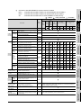
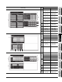
REVISIONS
* The manual number is given on the bottom left of the back cover.
Print Date
* Manual Number
Oct., 2004
SH (NA)-080523ENG-A
Mar., 2005
SH (NA)-080523ENG-B
Revision
First edition
Partial correction
Section 12.23, Section 12.28, Section 12.29, Section 12.31, Section 12.32
Jan., 2006
SH (NA)-080523ENG-C
Partial correction
Section 2.2, Section 9.1.2, Section 31.2.1,
Section 31.2.2 Section 31.2.3, Section 31.3
Partial addition
Section 3.9.3, Section 4.5, Section 6.3.2
Addition
Section 1.1.11, Section 3.10, Section 31.2.2, Chapter 32
Jun., 2006
SH (NA)-080523ENG-D
Partial correction
Section 6.3.3, Section 6.3.4
Section 6.3.5, Section 6.3.5
Section 6.3.6
Addition
Section 6.3.4
Nov., 2006
SH(NA)-080523ENG-E
Addition
Section 3.2.4
Nov., 2006
SH(NA)-080523ENG-F
Partial correction
Layouts were revised.
Titles of chapters and sections were revised.
Japanese Manual Version SH-080516-G
This manual confers no industrial property rights or any rights of any other kind, nor does it confer any patent licenses.
Mitsubishi Electric Corporation cannot be held responsible for any problems involving industrial property rights which may
occur as a result of using the contents noted in this manual.
2004 MITSUBISHI ELECTRIC CORPORATION
A-2
INTRODUCTION
Thank you for choosing the Mitsubishi Graphic Operation Terminal.
Please read this manual carefully so that equipment is used to its optimum.
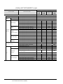
CONTENTS
SAFETY PRECAUTIONS .................................................................................................................................A - 1
REVISIONS.......................................................................................................................................................A - 2
INTRODUCTION...............................................................................................................................................A - 3
CONTENTS ......................................................................................................................................................A - 3
ABOUT MANUALS ......................................................................................................................................... A - 12
ABBREVIATIONS AND GENERIC TERMS IN THIS MANUAL...................................................................... A - 13
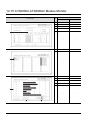
1 OVERVIEW
1.1
Features
1.1.1
1.1.2
1.1.3
1.1.4
1.1.5
1.1.6
1.1.7
1.1.8
1.1.9
1.1.10
1.1.11
1 - 1 to 1 - 17
1-1
Features of the utility function............................................................................................... 1 - 1
Features of the ladder monitor function ................................................................................ 1 - 3
Features of the system monitor function .............................................................................. 1 - 5
Features of the special module monitor function .................................................................. 1 - 7
Features of the network monitor function ............................................................................. 1 - 9
Features of the List editor function ..................................................................................... 1 - 11
Features of the motion monitor function ............................................................................. 1 - 12
Features of the servo amplifier monitor functions............................................................... 1 - 14
Features of the CNC monitor functions .............................................................................. 1 - 16
Features of the font change function .................................................................................. 1 - 17
Features of the system dialog language switching function ............................................... 1 - 17
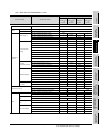
2 BEFORE BEGINNING OPERATION
2 - 1 to 2 - 15
2.1
Before getting started with various functions
2-1
2.2
Precautions before use
2-1
3 SPECIFICATIONS
3.1
Ladder monitor function specifications
3.1.1
3.1.2
3.1.3
3.2
3.3
3-2
PLC CPUs to be monitored .................................................................................................. 3 - 2
Access ranges to be monitored ............................................................................................ 3 - 2
Names of devices to be monitored ....................................................................................... 3 - 2
Precautions when using the system monitor function .......................................................... 3 - 2
Special module monitor function specifications
3.3.1
3.3.2
3.3.3
3.3.4
3-1
PLC CPUs to be monitored .................................................................................................. 3 - 1
Access ranges to be monitored ............................................................................................ 3 - 1
Precautions when using the ladder monitor function ............................................................ 3 - 1
System monitor function specifications
3.2.1
3.2.2
3.2.3
3.2.4
3 - 1 to 3 - 29
3-3
Access ranges to be monitored ............................................................................................ 3 - 4
Special function modules to be monitored............................................................................ 3 - 4
Memory capacity .................................................................................................................. 3 - 5
Precautions when using the special module monitor function .............................................. 3 - 6
A-3
3.4
Network monitor function specifications
3.4.1
3.4.2
3.4.3
3.5
3.6
3.8
3.9
3 - 26
CNC models that can be monitored.................................................................................... 3 - 26
CNC functions that can be monitored................................................................................. 3 - 26
Access ranges to be monitored .......................................................................................... 3 - 26
Precautions when using the CNC monitor function ............................................................ 3 - 26
Font change function specifications
3.9.1
3.9.2
3.9.3
3 - 21
List of servo amplifier models that can be monitored and functions ................................... 3 - 21
Access range that can be monitored .................................................................................. 3 - 21
Precautions for use of the servo amplifier monitor functions .............................................. 3 - 22
System configuration for servo amplifier connection .......................................................... 3 - 22
Screens and memory capacity ........................................................................................... 3 - 23
CNC monitor function specifications
3.8.1
3.8.2
3.8.3
3.8.4
3 - 20
PLC CPUs that can be monitored....................................................................................... 3 - 20
Access ranges that can be monitored ................................................................................ 3 - 20
Precautions for use of the motion monitor function ............................................................ 3 - 20
Memory space necessary to use the motion monitor function............................................ 3 - 20
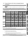
Specifications of the Servo Amplifier Monitor Functions
3.7.1
3.7.2
3.7.3
3.7.4
3.7.5
3 - 11
PLC CPU that allows for list edit......................................................................................... 3 - 11
Access range that allows for list edit................................................................................... 3 - 11
Precautions for List editor function ..................................................................................... 3 - 11
List of key arrangement and key functions ......................................................................... 3 - 12
Display format on the display.............................................................................................. 3 - 15
List of List editor function .................................................................................................... 3 - 18
Specifications of the motion monitor function
3.6.1
3.6.2
3.6.3
3.6.4
3.7
Network information to be monitored.................................................................................... 3 - 9
Access ranges to be monitored .......................................................................................... 3 - 10
Precautions when using the network monitor function ....................................................... 3 - 10
List editor function specifications
3.5.1
3.5.2
3.5.3
3.5.4
3.5.5
3.5.6
3-9
3 - 27
Available fonts .................................................................................................................... 3 - 27
Applicable range for each font ............................................................................................ 3 - 27
Precautions when using the font change function .............................................................. 3 - 28
3.10 System dialog language switching function specifications
3 - 29
3.10.1 Switchable languages......................................................................................................... 3 - 29
3.10.2 Precautions when using the system dialog language switching function ........................... 3 - 29
4 OPERATING THE UTILITY FUNCTION
4.1
Utility function table
4-1
4.2
Selecting the utility function
4-2
4.3
Utility Menu Screen
4-3
4.4
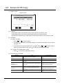
Screen & OS Copy
4-5
4.5
Setup
4-7
4.6
Self-Test
4 - 15
4.7
Memory Information
4 - 16
4.8
Clock
4 - 17
4.9
Screen Cleanup
4 - 18
4.10 Security Password
A-4
4 - 1 to 4 - 22
4 - 19
4.11 Password
4 - 20
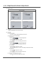
4.12 Brightness/Contrast Adjustment
4 - 21
LADDER MONITOR FUNCTION
5 OPERATING LADDER MONITOR
5 - 1 to 5 - 2
5.1
Operation procedures before starting ladder monitoring
5-1
5.2
Operation procedures from display of user-created monitor screen to start of ladder monitoring
5-2
6 OPERATING THE VARIOUS LADDER MONITOR SCREENS
6 - 1 to 6 - 30
6.1
Display screens
6-1
6.2
Screen operation and screen changes when monitoring
6-3
6.2.1
6.2.2
6.2.3
6.2.4
6.2.5
6.3
Reading data from the PLC .................................................................................................. 6 - 3
Ladder read operation .......................................................................................................... 6 - 9
Using the defect search ...................................................................................................... 6 - 12
Touch search operation ...................................................................................................... 6 - 16
Changing from one screen to another ................................................................................ 6 - 18
Ladder monitor
6.3.1
6.3.2
6.3.3
6.3.4
6.3.5
6.3.6
6 - 19
Ladder monitor screen display and key functions .............................................................. 6 - 19
Precaution during ladder monitoring................................................................................... 6 - 22
Switching displays .............................................................................................................. 6 - 24
Language switching (MELSEC-Q ladder monitor).............................................................. 6 - 26
Changing the device value ................................................................................................. 6 - 29
About Hardcopy Output ...................................................................................................... 6 - 30
7 ERROR MESSAGES FOR LADDER MONITOR
7 - 1 to 7 - 2
SYSTEM MONITOR FUNCTION
8 OPERATING SYSTEM MONITOR
8 - 1 to 8 - 2
8.1
Operation procedures before starting system monitoring
8-1
8.2
Operation procedures from user-created monitor screen display to start of system monitoring
8-2
9 OPERATION OF THE VARIOUS SYSTEM MONITOR SCREENS
9.1
Screen configuration, common operations and changing screens when monitoring
9.1.1
9.1.2
9.1.3
9.1.4
9.2
9.3
9-7
Basic operation ..................................................................................................................... 9 - 7
Entry monitor screen display and key functions ................................................................... 9 - 8
Deleting a registered device ................................................................................................. 9 - 9
Batch monitor
9.3.1
9.3.2
9-1
Basic screen configuration and key functions (menu) .......................................................... 9 - 1
Switching displays ................................................................................................................ 9 - 2
Specifying the monitor station and device (SET).................................................................. 9 - 4
Changing screens................................................................................................................. 9 - 6
Entry monitor
9.2.1
9.2.2
9.2.3
9 - 1 to 9 - 22
9 - 10
Basic operation ................................................................................................................... 9 - 10
Batch monitor screen display and key functions ................................................................ 9 - 11
A-5
9.4
TC Monitor (monitor of timer and counter)
9.4.1
9.4.2
9.5
9.6
9 - 12
Basic operation ................................................................................................................... 9 - 12
TC Monitor screen display and key functions ..................................................................... 9 - 13
BM Monitor (monitor of buffer memory)
9 - 14
9.5.1
9.5.2
Basic operation ................................................................................................................... 9 - 14
BM Monitor screen display and key functions .................................................................... 9 - 15
Test
9 - 16
9.6.1
9.6.2
Basic operation ................................................................................................................... 9 - 17
Quick test function .............................................................................................................. 9 - 20
10 ERROR MESSAGES FOR SYSTEM MONITOR
10 - 1 to 10 - 2
SPECIAL MODULE MONITOR FUNCTION
11 OPERATING SPECIAL MODULE MONITOR
11 - 1 to 11 - 2
11.1
Operation procedures before starting special module monitoring
11.2
Operation procedures from user-created monitor screen display to start of special module monitor
11 - 2
12 OPERATING SPECIAL MODULE MONITOR SCREEN
12.1
Screen configuration, common operation and changing screens when monitoring
12.1.1
12.1.2
12.1.3
12.1.4
12.1.5
12.1.6
12.1.7
12.1.8
11 - 1
12 - 1 to 12 - 82
12 - 1
Composition of system configuration screen and key functions ......................................... 12 - 1
Setting method for remote station monitoring..................................................................... 12 - 4
Composition of PC Information screen and key functions (only when QCPU(Q mode) is used)
............................................................................................................................................ 12 - 5
Composition of Unit Detail info screen and key functions (only when QCPU(Q mode) is used)
............................................................................................................................................ 12 - 6
Monitor screen configuration and key functions ................................................................. 12 - 7
Specifying monitor module and selecting monitor menu .................................................... 12 - 8
Test for special function module ......................................................................................... 12 - 9
Changing the screen......................................................................................................... 12 - 11
12.2
A61LS Module Monitor
12 - 12
12.3
AD61 Module Monitor
12 - 13
12.4
A1SD61 Module Monitor
12 - 14
12.5
A62DA-S1 Module Monitor
12 - 15
12.6
A1S62DA Module Monitor
12 - 16
12.7
A62LS Module Monitor
12 - 17
12.8
A1S62RD Module Monitor
12 - 18
12.9
A1S63ADA Module Monitor
12 - 19
12.10 A1S64AD Module Monitor
12 - 20
12.11 A68AD Module Monitor
12 - 21
12.12 A1S68AD Module Monitor
12 - 22
12.13 A68ADN Module Monitor
12 - 23
12.14 A68RD Module Monitor
12 - 24
A-6
12.15 A1S68DAI,A1S68DAV Module Monitor
12 - 25
12.16 A616AD Module Monitor
12 - 26
12.17 A616DAI,A616DAV Module Monitor
12 - 28
12.18 A616TD Module Monitor
12 - 29
12.19 AD70,A1SD70 Module Monitor
12 - 32
12.20 AD70D Module Monitor
12 - 34
12.21 AD71 Module Monitor
12 - 37
12.22 AD72,A1SD71 Module Monitor
12 - 40
12.23 AD75, A1SD75 Module Monitor
12 - 43
12.24 AJ71PT32-S3, A1SJ71PT32-S3 Module Monitor
12 - 49
12.25 AJ71ID1(ID2) -R4, A1SJ71ID1(ID2) -R4 Module Monitor
12 - 51
12.26 A84AD Module Monitor
12 - 52
12.27 A1S64TCTT(BW)-S1, A1S64TCRT(BW)-S1 Module Monitor
12 - 53
12.28 Q64AD,Q68ADV,Q68ADI Module Monitor
12 - 55
12.29 Q62DA,Q64DA Module Monitor
12 - 56
12.30 QD62,QD62D Module Monitor
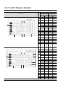
12 - 57
12.31 QD75P,QD75D Module Monitor
12 - 58
12.32 QD75M Module Monitor
12 - 69
13 OPERATING I/O MODULE MONITOR SCREENS
13 - 1 to 13 - 2
13.1
Specifying the module to be monitored
13 - 1
13.2
Monitor screen configuration and key functions
13 - 2
14 ERROR MESSAGES FOR SPECIAL MODULE MONITOR
14 - 1 to 14 - 2
NETWORK MONITOR FUNCTION
15 OPERATING NETWORK MONITOR
15 - 1 to 15 - 2
15.1
Steps in getting started with the network monitor function
15 - 1
15.2
Steps in starting the network monitor function from the user-created monitor screen
15 - 2
16 SWITCHING THE NETWORK MONITOR SCREENS
17 USING THE NETWORK MONITOR SCREENS
17.1
Own station monitor
17.1.1
17.2
17 - 1 to 17 - 18
17 - 1
Display contents and keys functions: own station monitor ................................................. 17 - 1
Detailed own station monitor
17.2.1
17.2.2
17.2.3
17.2.4
16 - 1 to 16 - 2
17 - 4
MELSECNET/B, MELSECNET (II) master station ............................................................. 17 - 4
MELSECNET/B, MELSECNET (II) local station ................................................................. 17 - 5
MELSECNET/10 Control station/ordinary Station .............................................................. 17 - 6
MELSECNET/10, MELSECNET/H remote master station ................................................. 17 - 9
A-7
17.3
Other station monitor
17.3.1
17.3.2
17.3.3
17.3.4
17.3.5
17.3.6
17.3.7
17 - 12
Other station monitor menu .............................................................................................. 17 - 12
Other station communication status monitor .................................................................... 17 - 13
Other station data link status monitor ............................................................................... 17 - 14
Other station parameter status monitor ............................................................................ 17 - 15
Other station CPU action status monitor .......................................................................... 17 - 16
Other station CPU RUN status monitor ............................................................................ 17 - 17
Other station loop status monitor...................................................................................... 17 - 18
18 ERROR MESSAGES FOR NETWORK MONITOR
18 - 1 to 18 - 2
LIST EDITOR FUNCTION
19 OPERATING LIST EDITOR
19 - 1 to 19 - 5
19.1
Operation procedures before starting the list edit
19 - 1
19.2
Operation procedures from user-created monitor screen display to starting list editing
19 - 2
19.2.1
19.2.2
Operation of keyword input................................................................................................. 19 - 3
Selection and operation of mode ........................................................................................ 19 - 5
20 OPERATION OF EDITING SCREEN FOR EACH LIST
20.1
Basic operation of key input
20.1.1
20.1.2
20.1.3
20.2
20.3
20 - 7
Reading sequence program ............................................................................................... 20 - 7
Changing (overwriting) command....................................................................................... 20 - 8
Adding (inserting) command............................................................................................... 20 - 9
Deleting command............................................................................................................ 20 - 10
Using Help function........................................................................................................... 20 - 11
Operation procedure list of list edit
20.3.1
20.3.2
20.3.3
20.3.4
20.3.5
20.3.6
20.3.7
20 - 1
Switching of valid key (function indicated at the upper/lower part of the key) .................... 20 - 1
Command input procedures ............................................................................................... 20 - 2
Action if an incorrect key is input ........................................................................................ 20 - 6
Basic operation of list edit
20.2.1
20.2.2
20.2.3
20.2.4
20.2.5
20 - 1 to 20 - 17
20 - 13
Common operation ........................................................................................................... 20 - 13
Operation in Write mode (W) ............................................................................................ 20 - 13
Operation in Read mode (R)............................................................................................. 20 - 14
Operation in Insert mode (I).............................................................................................. 20 - 14
Operation in Delete (D) mode........................................................................................... 20 - 14
Operation in Parameter mode (P)..................................................................................... 20 - 15
Operation in Other modes (O) .......................................................................................... 20 - 16
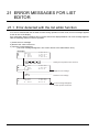
21 ERROR MESSAGES FOR LIST EDITOR
21 - 1 to 21 - 6
21.1
Error detected with the list editor function
21 - 1
21.2
Error of PLC CPU
21 - 4
21.3
Error using list editor function on the link system
21 - 5
A-8
MOTION MONITOR FUNCTION
22 OPERATING MOTION MONITOR
22 - 1 to 22 - 4
22.1
Operation procedures before starting motion monitoring
22 - 1
22.2
Operation procedures from user-created monitor screen display to start of motion monitor
22 - 2
22.2.1
Password entry operation procedure.................................................................................. 22 - 4
23 OPERATIONS OF VARIOUS MOTION MONITOR SCREENS
23.1
23 - 1 to 23 - 17
Screen layout, common operations and screen changes for monitoring
23.1.1
23 - 1
System configuration screen layout and key functions....................................................... 23 - 1
23.2
Changing the screen
23 - 3
23.3
Motion monitor
23 - 4
23.3.1
23.3.2
23.3.3
23.3.4
23.3.5
23.3.6
23.3.7
23.4
Parameter setting
23.4.1
23.4.2
23.5
Display data and key functions of present value monitor screen ....................................... 23 - 5
Display data and key functions of SFC error history screen............................................... 23 - 6
Display data and key functions of error list screen ............................................................. 23 - 7
Display data and key functions of error list designated-axis screen ................................... 23 - 8
Display data and key functions of positioning monitor screen .......................................... 23 - 10
Display data and key functions of servo monitor screen .................................................. 23 - 12
Display data and key functions of present value history monitor screen .......................... 23 - 13
23 - 15
Display data and key functions of parameter setting screen ............................................ 23 - 15
Parameter setting operation ............................................................................................. 23 - 16
About Hardcopy Output
24 ERROR MESSAGES FOR MOTION MONITOR
23 - 17
24 - 1 to 24 - 2
SERVO AMPLIFIER MONITOR FUNCTION
25 OPERATING SERVO AMPLIFIER MONITOR
25 - 1 to 25 - 2
25.1
Operation procedures before starting motion monitoring
25 - 1
25.2
Operation procedures from user-created monitor screen display to start of motion monitor
25 - 2
26 OPERATIONS OF SERVO AMPLIFIER MONITOR SCREENS
26 - 1 to 26 - 36
26.1
Screen Transition
26 - 1
26.2
About the Servo Amplifier Monitor Functions
26 - 2
26.3
Setup
26 - 3
26.3.1
26.4
Monitor Functions
26.4.1
26.5
26 - 7
Alarm display screen .......................................................................................................... 26 - 8
Alarm history screen ........................................................................................................... 26 - 9
Diagnostics Function
26.6.1
26 - 5
Monitor screen .................................................................................................................... 26 - 5
Alarm Function
26.5.1
26.5.2
26.6
Setup screen ...................................................................................................................... 26 - 3
26 - 10
DI/DO display screen........................................................................................................ 26 - 13
A-9
26.6.2
26.6.3
26.6.4
26.6.5
26.7
Parameter Setting
26.7.1
26.7.2
26.7.3
26.8
26 - 18
Password entry operation procedure................................................................................ 26 - 19
Parameter setting screen.................................................................................................. 26 - 20
Parameter setting operation ............................................................................................. 26 - 22
Test Operations
26.8.1
26.8.2
26.8.3
26.8.4
26.8.5
26.8.6
26.9
Function device display screen......................................................................................... 26 - 14
Amplifier information display screen ................................................................................. 26 - 15
ABS data display screen................................................................................................... 26 - 16
Unit composition list display screen.................................................................................. 26 - 17
26 - 24
Precautions for test operations ......................................................................................... 26 - 27
Preparations for test operations........................................................................................ 26 - 28
JOG operation screen....................................................................................................... 26 - 29
Positioning operation screen ............................................................................................ 26 - 30
Motorless operation screen .............................................................................................. 26 - 32
DO forced output screen................................................................................................... 26 - 33
About Hardcopy Output
27 ERROR MESSAGES FOR SERVO AMPLIFIER MONITOR
26 - 34
27 - 1 to 27 - 2
CNC MONITOR FUNCTION
28 OPERATING CNC MONITOR
28.1
Operation procedures before starting CNC monitoring
29 OPERATING THE CNC MONITOR FUNCTION SCREEN
28 - 1 to 28 - 2
28 - 1
29 - 1 to 29 - 3
29.1
Changing screens
29 - 1
29.2
About the CNC Monitor Functions
29 - 2
30 ERROR MESSAGES FOR CNC MONITOR
30 - 1 to 30 - 2
OTHER EXTENDED/OPTION FUNCTIONS
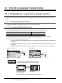
31 FONT CHANGE FUNCTION
31.1
Preparation to use the font change function
31.1.1
31.1.2
31.1.3
31.2
31.3
Troubleshooting when font cannot be changed.
Preparation to use the system dialog language switching function
32.1.1
A - 10
31 - 3
Setting the font change device ........................................................................................... 31 - 3
Displaying Chinese (simplified characters) fonts with Preview of GT Designer2 ............... 31 - 4
Installing font data............................................................................................................... 31 - 8
32 SYSTEM DIALOG LANGUAGE SWITCHING
32.1
31 - 1
Checking the required devices ........................................................................................... 31 - 1
Checking the ROM_BIOS version ...................................................................................... 31 - 1
Checking the OS................................................................................................................. 31 - 2
Operation of the font change function
31.2.1
31.2.2
31.2.3
31 - 1 to 31 - 10
31 - 10
32 - 1 to 32 - 4
32 - 1
Checking the required devices ........................................................................................... 32 - 1
32.1.2
32.1.3
32.2
Checking the ROM_BIOS version ...................................................................................... 32 - 1
Checking the OS ................................................................................................................ 32 - 1
Operation of the system dialog language switching function
32.2.1
32.3
INDEX
32 - 2
Setting the system dialog language switching device ........................................................ 32 - 2
Example of system dialog language display
32 - 3
Index - 1 to Index - 2
A - 11
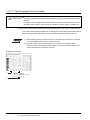
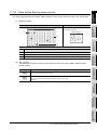
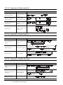
ABOUT MANUALS
The following manuals related to this product are available. Obtain the manuals as
required the according to this table.
Related manual
Manual name
GT Designer2 Version2 Operating Manual (Startup
Manual number (type code)
Introductory Manual)
SH-080520ENG
Describes methods of installing GT Designer2 and introductory drawing methods.
(Sold separately)
GT Designer2 Version2 Operating Manual
(1DM215)
SH-080521ENG
Describes methods of operating GT Designer2 and transmitting data to GOT.
(Sold separately)
GT Designer2 Version2 Reference Manual
Describes the specifications and settings of each object function used in GT Designer2.
(Sold separately)
(1DM216)
SH-080522ENG
(1DM217)
GOT-A900 Series Operating Manual
(GT Designer2 Version2 compatible Gateway Functions Manual)
Describes the gateway function specifications, system configuration and methods of setting GOTA900 series.
SH-080525ENG
(1DM220)
(Sold separately)
A985GOT/A975GOT/A970GOT/A960GOT User’s Manual
Provides performance specification, setting method, and communication board/communication mod-
SH-4005
ule installation method of each GOT.
(1DM099)
(Sold separately)
A950GOT/A951GOT/A953GOT/A956GOT User’s Manual
Provides performance specification, setting method, and communication board/communication module installation method of each GOT.
SH-080018
(1DM103)
(Sold separately)
GOT-A900 Series User’s Manual
(GT Designer2 Version2 compatible Connection System Manual)
Describes the system configuration of which connection method is compatible with GOT-A900 series
as well as processing cables.
SH-080524ENG
(1DM219)
(Sold separately)
GT SoftGOT2 Version1 Operating Manual
SH-080400E
Describes the system configuration, screen makeup and usage of GT SoftGOT2.
(Sold separately)
A - 12
(1DM210)
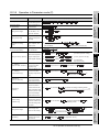
ABBREVIATIONS AND GENERIC TERMS IN THIS MANUAL
Abbreviations, generic terms and special terms used in this manual are described as follows:
Abbreviations, generic terms
and special terms
A985GOT-V
A985GOT
Description
Generic term of A985GOT-TBA-V and A985GOT-TBD-V
Generic term of A985GOT-TBA, A985GOT-TBD and A985GOT-TBA-EU
Generic term of A975GOT-TBA-B, A975GOT-TBD-B, A975GOT-TBA, A975GOT-TBD and
A975GOT
A975GOT-TBA-EU
Generic term of A970GOT-TBA-B A970GOT-TBD-B, A970GOT-TBA, A970GOT-TBD,
A970GOT
A970GOT-SBA, A970GOT-SBD, A970GOT-LBA, A970GOT-LBD, A970GOT-TBA-EU and
A970GOT-SBA-EU
A97*GOT
Generic term of A975GOT and A970GOT
A960GOT
Generic term of A960GOT-EBA, A960GOT-EBD and A960GOT-EBA-EU
A956WGOT
Generic term of A956WGOT-TBD
Generic term of A956GOT-TBD, A956GOT-SBD, A956GOT-LBD, A956GOT-TBD-M3,
A956GOT
A956GOT-SBD-M3, A956GOT-LBD-M3, A956GOT-SBD-B and A956GOT-SBD-M3-B
GOT
Generic term of A953GOT-TBD, A953GOT-SBD, A953GOT-LBD, A953GOT-TBD-M3,
A953GOT
A953GOT-SBD-M3, A953GOT-LBD-M3, A953GOT-SBD-B and A953GOT-SBD-M3-B
Generic term of A951GOT-TBD, A951GOT-SBD, A951GOT-LBD, A951GOT-TBD-M3,
A951GOT
A951GOT-SBD-M3, A951GOT-LBD-M3, A951GOT-SBD-B and A951GOT-SBD-M3-B
Generic term of A951GOT-QTBD, A951GOT-QSBD, A951GOT-QLBD, A951GOT-QTBD-M3,
A951GOT-Q
A951GOT-QSBD-M3, A951GOT-QLBD-M3, A951GOT-QSBD-B and A951GOT-QSBD-M3-B
Generic term of A950GOT-TBD, A950GOT-SBD, A950GOT-LBD, A950GOT-TBD-M3,
A950GOT
A950GOT-SBD-M3, A950GOT-LBD-M3, A950GOT-SBD-B and A950GOT-SBD-M3-B
Generic term of A953GOT-SBD-M3-H, A953GOT-LBD-M3-H, A950GOT-SBD-M3-H and
A950 handy GOT
A950GOT-LBD-M3-H
Generic term of A956GOT, A953GOT, A951GOT, A951GOT-Q, A950GOT and A950 handy
A95*GOT
GOT
Communica- Bus connection board
Generic term of A9GT-QBUSS, A9GT-QBUS2S, A9GT-BUSS and A9GT-BUS2S
Serial communication board Generic term of A9GT-RS4, A9GT-RS2 and A9GT-RS2T
tion board
Generic term of A9GT-QBUS2SU, A9GT-BUS2SU, A9GT-BUS2SU, A7GT-BUSS and A7GTBus connection unit
BUS2S
Generic term of A9GT-QJ71LP23, A9G1-QJ71BR13, A7GT-J71AP23, A7GT-J71AR23 and
Communica- Data link unit
A7GT-J71AT23B
tion unit
Network unit
Generic term of A9GT-QJ71LP23, A9GT-QJ71BR13, A7GT-J71LP23 and A7GT-J71BR13
CC-Link communication unit Generic term of A8GT-J61BT13 and A8GT-J61BT15
Ethernet unit
Generic term of A9GT-J71E71-T
Abbreviation of A9GT-80PSC, A9GT-70PSC, A9GT-60PSC and A9GT-50PSC type transparent
Protection sheet
protection sheets
Abbreviation of A9GT-80LTT, A9GT-70LTTB, A9GT-70LTT, A9GT-70LTS, A9GT-70LTTBW and
Backlight
A9GT-50LT type backlights
Debug stand
Abbreviation of A9GT-80STAND, A9GT-70STAND and A9GT-50STAND type debug stand
Memory card
Flash PC card/Commercially available flash PC card/SRAM type PC card
Flash PC card
Generic term of A9GTMEM-10MF, A9GTMEM-20MF and A9GTMEM-40MF
Option
Compact flash PC card
Commercially available flash PC card
Abbreviation of A9GT-FNB, A9GT-FNB1M, A9GT-FNB2M, A9GT-FNB4M, A9GT-FNB8M,
Memory board
A9GT-QFNB, A9GT-QFNB4M, A9GT-QFNB8M type option function memory board
Attachment
Generic term of A77GT-96ATT/A85GT-95ATT/A87GT-96ATT/A87GT-97ATT attachments
Ten-key Panel
Abbreviation of A8GT-TK ten-key Panel
A7GT-CNB
Abbreviation of A7GT-CNB bus connector conversion box
A9GT-QCNB
Abbreviation of A9GT-QCNB bus connector conversion box
External I/O module
Abbreviation of A9GT-70KBF and A8GT-50KBF type external I/O interface module
Printer interface module
Abbreviation of A9GT-50PRF type printer interface module
Memory card interface modAbbreviation of A1SD59J-MIF memory card interface module
ule
Option unit
Video/RGB mixed input
Abbreviation of A9GT-80V4R1 type Video/RGB mixed input interface module
interface module
Video input interface module Abbreviation of A9GT-80V4 type Video input interface module
RGB input interface module Abbreviation of A9GT-80R1 type RGB input interface module
GT Designer2 Version2
Generic term of SW2D5C-GTD2-E software
GT Designer
Abbreviation of image creation software GT Designer for GOT900
GT Converter2
Abbreviation of data conversion software GT Converter for GOT900
GT SoftGOT2
Abbreviation of GT SoftGOT2 monitoring software
Software
GX Developer
Generic term of SW D5C-GPPW-E/SW D5F-GPPW-E software packages
GX Simulator
Generic term of SW D5C-LLT-E ladder logic test tool function software packages
(SW5D5C-LLT-E or later)
A - 13
Abbreviations, generic terms
and special terms
QCPU (Q Mode)
QCPU (A Mode)
Remote I/O station
QCPU
QnACPU Type
CPU
QnASCPU Type
QnACPU
AnUCPU
AnACPU
AnNCPU
AnCPU Type
AnUS(H)CPU
AnS(H)CPU
A1SJ(H)CPU
AnSCPU Type
ACPU
FXCPU
G4
Abbreviation of AJ65BT-G4-S3
QE71
Q series-compatible E71
Omron PLC
Yasukawa PLC
SLC500 Series
MicroLogix1000 Series
MicroLogix1500 Series
Allen-Bradley PLC
Sharp PLC
Other PLC
PROSEC T Series
PROSEC V Series
Toshiba PLC
SIEMENS PLC
Large type H series
H200 to 252 Series
H Series board type
Others
Generic term of FX0 series, FX0N series, FX0S series, FX1 series, FX1N series, FX1S series,
FX2 series, FX2C series, FX2N series, FX1NC series and FX2NC series CPU
FA controller
E71
Ethernet
module
Generic term of Q00JCPU, Q00CPU, Q01CPU,Q02CPU, Q02HCPU, Q06HCPU, Q12HCPU,
Q25HCPU, Q12PHCPU, Q25PHCPU,Q12PRHCPU and Q25PRHCPU CPU
Generic term of Q02CPU-A, Q02HCPU-A and Q06HCPU-A CPU
Network module for MELSECNET/H network system remote I/O station
(QJ72LP25-25, QJ72LP25G, QJ72BR15)
Generic term of QCPU (Q Mode), QCPU (A Mode) and Remote I/O station
Generic term of Q2ACPU, Q2ACPU-S1, Q2AHCPU, Q2AHCPU-S1, Q3ACPU, Q4ACPU and
Q4ARCPU CPU
Generic term of Q2ASCPU, Q2ASCPU-S1, Q2ASHCPU and Q2ASHCPU-S1 CPU
Generic term of QnACPU Type and QnASCPU Type
Generic term of A2UCPU, A2UCPU-S1, A3UCPU and A4UCPU CPU
Generic term of A2ACPU, A2ACPU-S1 and A3ACPU CPU
Generic term of A1NCPU, A2NCPU, A2NCPU-S1 and A3NCPU CPU
Generic term of AnUCPU, AnACPU and AnNCPU CPU
Generic term of A2USCPU, A2USCPU-S1 and A2USHCPU-S1 CPU
Generic term of A1SCPU, A1SCPUC24-R2, A2SCPU, A2SCPU-S1, A1SHCPU, A2SHCPU
and A2SHCPU-S1 CPU
Generic term of A1SJCPU, A1SJCPU-S3 and A1SJHCPU CPU
Generic term of A2US(H)CPU, AnS(H)CPU and A1SJ(H)CPU CPU
Generic term of AnCPU Type, AnSCPU Type, A1FXCPU, A0J2HCPU, A2CCPU, A2CCPU24
and A2CJCPU CPU
Generic term of A273UCPU, A273UHCPU, A273UHCPU-S3, A373CPU, A373UCPU,
A373UCPU-S3, A171SCPU, A171SCPU-S3, A171SCPU-S3N, A171SHCPU, A171SHCPUN,
A172SHCPU, A172SHCPUN, A173UHCPU, A173UHCPU-S1, Q172CPU, Q173CPU,
Q172CPUN and Q173CPUN CPU
Generic term of LM610, LM7600, LM8000 CPU
Motion controller CPU
Peripheral
connection
module
Description
EH-150 Series
HITACHI PLC
(HIDIC H Series)
Matsushita Electric Works
PLC
Memory
OS
Object
Personal Computer
Servo amplifier
MELDAS C6/C64
Generic of AJ71E71-S3, AJ71E71N-B2, AJ71E71N-B5, AJ71E71N-T, AJ71E71N-B5T,
A1SJ71E71-B2-S3, A1SJ71E71-B5-S3, A1SJ71E71N-B2, A1SJ71E71N-B5, A1SJ71E71N-T
and A1SJ71E71N-B5T
Generic of AJ71QE71, AJ71QE71-B5, AJ71QE71N-B2, AJ71QE71N-B5, AJ71QE71N-T,
AJ71QE71N-B5T, A1SJ71QE71-B2, A1SJ71QE71-B5, A1SJ71QE71N-B2, A1SJ71QE71NB5, A1SJ71QE71N-T and A1SJ71QE71N-B5T
Generic of QJ71E71, QJ71E71-B2, QJ71E71-B5 and QJ71E71-100
Generic term of C200HS, C200H, C200H series(C200HX, C200HG, C200HE), CQM1,
C1000H,C2000H,CV500, CV1000, CV2000, CVM1-CPU11, CVM1-CPU21, CS1, CS1D,
CJ1M, CPM1, CPM1A, CPM2A, CPM2C CPU, CQM1H
Generic term of GL60S, GL60H, GL70H, GL120, GL130, CP-9200SH, CP-9300MS, MP-920,
MP-930, MP-940, CP-9200(H) and PROGIC-8 CPU
Generic term of SLC500-20, SLC500-30, SLC500-40, SLC5/01 SLC5/02, SLC5/03, SLC5/04
SLC5/05
Generic term of 1761-L10BWA, 1761-L10BWB, 1761-L16AWA, 1761-L16BWA, 1761L16BWB, 1761-L16BBB, 1761-L32AWA, 1761-L32BWA, 1761-L32BWB, 1761-L32BBB,
1761-L32AAA, 1761-L20AWA-5A, 1761-L20BWA-5A, 1761-L20BWB-5A
Abbreviation of 1764-LSP
Generic term of SLC 500 Series, MicroLogix1000 Series, MicroLogix1500 Series
Generic term of JW-21CU, JW-22CU, JW-31CUH, JW-32CUH, JW-33CUH, JW-50CUH,
JW-70CUH, JW-100CUH, JW-100CU, Z-512J CPU
Generic term of T2(PU224 type), T2E, T2N, T3, T3H CPU
Abbreviation of Model3000(S3) CPU
Generic term of PROSEC T Series and PROSEC V Series
Generic term of SIMATIC S7-300 Series and SIMATIC S7-400 Series CPU
Generic term of H-302(CPU2-03H), H-702(CPU2-07H), H-1002(CPU2-10H), H-2002(CPU220H), H-4010(CPU3-40H),.J-300(C0PU-03Ha), H-700(CPU-07Ha), H-2000(CPU-20Ha)
Generic term of H-200(CPU-02H, CPE-02H), H-250(CPU21-02H), H-252(CPU22-02H), H252B(CPU22-02HB), H-252C(CPU22-02HC, CPE22-02HC)
Generic term of H-20DR, H-28DR, H-40DR, H-64DR, H-20DT, H-28DT, H-40DT, H-64DT, HL40DR, HL-64DR
Generic term of EH-CPU104, EH-CPU208, EH-CPU308, EH-CPU316
Generic term of large type H series,H-200 to 252 Series H Series board type, EH-150 Series
Generic term of FP0-C16CT, FP0-C32CT, FP1-C24C, FP1-C40C, FP2, FP2SH, FP3, FP5,
FP10(S), FP10SH, FP-M(C20TC) and FP-M(C32TC)
abbreviation of memory (flash memory) in the GOT
Abbreviation of GOT system software
Setting data for dynamic image
Personal computer where the corresponding software package is installed
Generic term of the MR-J2S- A, MR-J2S- CP and MR-J2M A series
Generic term of the FCA C6, FCA C64
* In this manual, the following products are called by new names.
Old Name
New Name
GPPW
GX Developer
Generic term of SW
A - 14
D5C-GPPW-E/SW
Remarks
D5F-GPPW-E software packages
Note that some functions cannot be performed depending on the used GOT and the
target CPU/connection form.
Refer to Chapter 2 for more information on the functions available for each GOT and
the restrictions on the functions per target CPU and connection form.
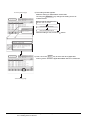
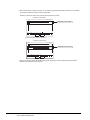
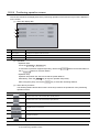
1.1 Features
1.1.1
2
3
4
OPERATING THE
UTILITY FUNCTION
The monitor functions described in this manual are intended to improve the efficiency of trouble-shooting and
maintenance operations for the PLC system.
The features of each monitor function are explained in the following sections.
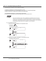
OVERVIEW
This manual that can be used on a GOT with an operating system installed. These functions include the utility function, ladder monitor function, system monitor function, special module monitor function, network monitor function, list editor function, motion monitor function, servo amplifier monitor function and CNC monitor
function.
BEFORE BEGINNING OPERATION
OVERVIEW
SPECIFICATIONS
1
1
Features of the utility function
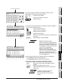
The utility function enables you to use GOT setup and self-tests. To use the utility function, you need to
install an operating system for the utility function on the GOT built-in internal memory by using GT
Designer2. The features of the utility function are shown below.
OPERATING LADDER MONITOR
5
Some of the utility functions cannot be used with GT SoftGOT2. Refer to the GT
SoftGOT2 Version1 Operating Manual for the utility functions available for GT
SoftGOT2.
6
OPERATING THE
VARIOUS LADDER
MONITOR SCREENS
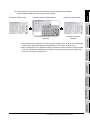
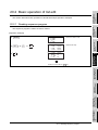
(1) The brightness of a monitor screen can be adjusted (see Section 4.3 for details).
ERROR MESSAGES
FOR LADDER MONITOR
7
OPERATING SYSTEM MONITOR
8
1.1 Features
1.1.1 Features of the utility function
1-1
(2) The screen and OS data can be copied between the internal memory and memory card (see
Section 4.4 for details).
The data monitored can be copied to and from the GOT built-in internal memory or a memory card
installed on the GOT.
The OS data can only be copied from the GOT to the memory card.
(3) Setting a use environment of the GOT (see Section 4.5 for details).
You can set the operating environment of the GOT such as the beep sound, message display
language and screen saver's idle time. When using the A985GOT, you can also make settings on
the Human sensor.
1-2
1.1 Features
1.1.1 Features of the utility function
1
OVERVIEW
(4) Running diagnostic checks on GOT hardware (see Section 4.6).
BEFORE BEGINNING OPERATION
2
SPECIFICATIONS
3
You can run diagnostic checks on the GOT hardware, including the image check, font check,
memory card check and so on.
(5) Other functions (see Section 4.7 for details)
• Displaying data on available space in the GOT internal memory.
• Adjusting the clock of the PLC CPU.
• Displaying the display area cleanup screen.
• Changing security levels.
• Limiting access to the Utility Menu screen.
OPERATING THE
UTILITY FUNCTION
5
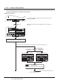
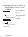
Features of the ladder monitor function
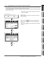
Installing the ladder monitor function operating system into the GOT built-in memory using the GT Designer2
enables ladder monitoring of the PLC CPU program as shown in a ladder diagram. The features of the ladder monitor function are shown below.
6
STEP : 12345/18374
K
MOV 1
D1
K
MOV 2
D2
D100
MOV
MOV
MOV
K
DUTY 350
D2
D1
1
V
2
D162
47
D167
90
RST
K
90
K
110
K
100
V
SET
K
400
M9028
D162
7
D167
ERROR MESSAGES
FOR LADDER MONITOR
K
1234
=
OPERATING THE
VARIOUS LADDER
MONITOR SCREENS
(1) Monitoring based on ladder symbols (see Section 6.3 for details)
(Sample display) Ladder monitor screen
P0
M999
187
D172
M9020
D172
110
100
DATA OVERFLOWS ONE SCREEN
PLCRD.
Mon.
Menu
Print
Screen
List
8
Cancel
Print
OPERATING SYSTEM MONITOR
Exit
OPERATING LADDER MONITOR
1.1.2
4
1.1 Features
1.1.2 Features of the ladder monitor function
1-3
Remark
The Print Screen and Cancel Print buttons are not displayed on the A956WGOT
or the GOT whose display screen type is the EL.
1)
Remark
Ladder monitor screen
A maximum of 8 lines (max. 11 contact points per line; with 12 contact points or
more, the line returns) of a sequence program are displayed on one screen.
Also, for the current values and other settings of word devices, a maximum of 8
devices are displayed (With 9 devices or more, use the arrow keys to switch
displays.).
Depending on the GOT model, a display is provided on the MELSEC-Q ladder monitor
screen as indicated below.
• A985GOT(-V): Max. 15 lines displayed (1 line: Max. 11 contacts)
• A956WGOT: Max. 5 lines displayed (1 line: Max. 7 contacts)
(2) The display format can be changed to show comments for devices (see Section 6.2.2 for details).
(Sample display) Ladder monitor screen
STEP : 12345/18374
M9036
PLS M910
Character string
display
0
Normally ON
Action
X0001
X0002
4
Ready
display
Y0023
Operation ready
Start
operation
instruction
K25
T0
Operation start
warning
7
25
T0
Exit
PCRD.
Mon.
Menu
Print
Screen
List
Cancel
Print
1) Switching the display format
The current values monitor of the word devices at the bottom of the screen are executed in
decimal or hexadecimal format.
2) Displaying device comments
Comments of for the device used in the PLC program (comments that are written into the
PLC CPU) are displayed.
(3) Monitoring other stations
Other stations in data link systems, network system or CC-Link system, including the GOT (or
stations connected to the GOT), can be monitored.
1-4
1.1 Features
1.1.2 Features of the ladder monitor function
1
Features of the system monitor function
Installing the screen monitor function operating system into the GOT built-in memory using the GT Designer2
enables monitoring and testing of the buffer memory for the PLC CPU program and the special functions
module. The features of the system monitor function are shown below.
2
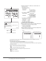
Batch monitor
DEVICE MONITOR TEST MENU FORM SET
NETWK No. [ 0]
STATION[FF]
43
68378428
30000
DW
10
11
12
13
14
15
16
17
32767
0
0
-1
0
3
0
0
D
D
D
D
D
D
D
D
18
19
20
21
22
23
24
25
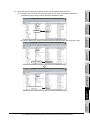
• Up to 8 points for a PLC CPU
device registered by the user
can be monitored in one window (see Section 9.2).
• Up to 16 points subsequent to
a PLC CPU device specified by
the user can be monitored in
one window (see Section 9.3).
T/C monitor
Buffer memory monitor
TC MONITOR
NETWK No. [ 0]
0 PV
0
[Production line
T
1 PV
0
[Production line
T
2 PV 150
[Production line
T
3 PV
0
[Production line
SV
A
SV
B
SV
C
SV
D
4
BM MONITOR TEST MENU FORM SET
NETWK No. [ 0]
STATION[FF]
I/O NO[ 1]
BM 1110 -32767
BM 1118
0
BM 1111
64
BM 1119
0
BM 1112
149
BM 1120
150
BM 1113
-1111
BM 1121
131
BM 1114
126
BM 1122 -32768
BM 1115
160
BM 1123
555
BM 1116
255
BM 1124
2368
BM 1117
1200
BM 1125 11000
TEST MENU FORM SET
STATION[FF]
T
3
-500
3234
0
0
0
-32768
0
0
SPECIFICATIONS
D
D
D
D
D
D
D
D
DW
OPERATING THE
UTILITY FUNCTION
-2147483648
-32767
0
]
0
]
150
]
0
]
5
OPERATING LADDER MONITOR
15
10
001
25
70
200
50
300
BATCH MONITOR TEST MENU FORM SET
NETWK No. [ 0]
STATION[FF]
• Up to 16 points subsequent to
the buffer memory of a special
function module specified by
the user can be monitored in
one window (see Section 9.5).
• Up to 8 points, including the
current value, set value, contact point, and coil can be monitored in a window subsequent
to a PLC CPU timer (T)/counter
(C) specified by the user (see
Section 9.4).
6
OPERATING THE
VARIOUS LADDER
MONITOR SCREENS
D
D
X
M
Y
W
R
D
BEFORE BEGINNING OPERATION
(1) Any desired device can be monitored, using 4 dedicated screens
The system monitor function provides an entry monitor, a batch monitor, and a buffer memory
monitor, enabling monitoring of any device, for complete flexibility in any application.
Entry monitor
OVERVIEW
1.1.3
• With the GOT, the full screen can be divided into four windows and separate monitoring carried out in all four windows simultaneously.
7
15
10
001
25
70
200
50
300
-2147483648
-32767
TC MONITOR
NETWK No.[ 0]
T
DW
43
68378428
30000
DW
TEST MENU FORM SET
STATION[FF]
0 PV
0
[Production line
T
1 PV
0
[Production line
T
2 PV 150
[Production line
T
3 PV
0
[Production line
SV
A
SV
B
SV
C
SV
D
0
]
0
]
150
]
0
]
D
D
D
D
D
D
D
D
10
11
12
13
14
15
16
17
32767
0
0
-1
0
3
0
0
D
D
D
D
D
D
D
D
18
19
20
21
22
23
24
25
ERROR MESSAGES
FOR LADDER MONITOR
D
D
X
M
Y
W
R
D
BATCH MONITOR TEST MENU FORM SET
NETWK No.[ 0]
STATION[FF]
-500
3234
0
0
0
-32768
0
0
BM MONITOR TEST MENU FORM SET
NETWK No.[ 0]
STATION[[FF]
I/O NO[ 1]
BM 1110 -32767
BM 1118
0
BM 1111
64
BM 1119
0
BM 1112
149
BM 1120
150
BM 1113
-1111
BM 1121
131
BM 1114
126
BM 1122 -32768
BM 1115
160
BM 1123
555
BM 1116
255
BM 1124
2368
BM 1117
1200
BM 1125 11000
8
OPERATING SYSTEM MONITOR
DEVICE MONITOR TEST MENU FORM SET
NETWK No.[ 0]
STATION[FF]
1.1 Features
1.1.3 Features of the system monitor function
1-5
(2) Data can be changed by test operation (see Section 9.6 for details).
(Test sample)
When M0 is on
NETWK No.[ 0]
DEVICE[ M] [
STATION[FF]
DEC
0]
RST:0 SET:1[1]
When changing D0 present value
NETWK No.[ 0]
DEVICE[ D] [
STATION[FF]
DEC
0]
VL[ K-2147483648 ]
7
8
9
A
B
7
8
9
A
B
4
5
6
C
D
4
5
6
C
D
1
2
3
E
F
1
2
3
E
F
0
−
0
−
AC DEL
AC DEL
1) Test for bit device
Device specified by user is turned on or off.
2) Test for word device
Writes designated value into device specified by user.
3) Test for timer/counter
Writes in designated value as current value or set values of device specified by user.
4) Test for buffer memory
Writes designated value into buffer memory specified by user.
(3) Display format can be changed and device comments can be displayed (see Section 9.1.2 for
details).
(Sample display)
For entry monitor
(comment display)
For batch monitor
(hexadecimal display)
DEVICE MONITOR TEST MENU FORM SET
NETWKNo.[ 0] STATION[FF]
BATCHMONITOR TEST MENU FORM SET
NETWK No.[ 0] STATION[FF]
D
W
R
X
200
30
[Line 1 current units ]
200
43
[Production line A
]
50
68378428 DW
[link status
]
3
[Input switch 3
]
D
D
D
D
D
D
D
D
10
11
12
13
14
15
16
17
H
H
H
H
H
H
H
H
7FFF
0000
0000
FFFF
0000
0003
0000
0000
D
D
D
D
D
D
D
D
18
19
20
21
22
23
24
25
H
H
H
H
H
H
H
H
FE0C
0CA2
0000
0000
0000
8000
0000
0000
1) Changing display format
The word device values for the entry monitor, batch monitor, T/C monitor, and the buffer
memory monitor are monitored in decimal or hexadecimal format.
2) Device comment display
When the PLC CPU device is monitored, the comments written into the PLC CPU are
displayed.
(4) Other stations can be monitored.
Other stations in data link systems, network systems or CC-Link systems, including the GOT (or
stations connected to the GOT), can be monitored.
1-6
1.1 Features
1.1.3 Features of the system monitor function
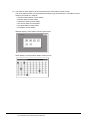
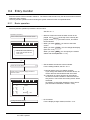
(1) Monitoring can be done with dedicated screens (see Section 12.2 for details).
Monitoring is carried out using dedicated screens provided by the manufacturer for the special
function module and I/O module.
It is not necessary for the user to create monitor screens.
3
(Sample display 1: for special function module)
A68RD
Graph monitor screen
*********
87654321
0000000000000000
1:*** 0:***
600
500
1 Operation Monitor
2 I/O Monitor
3 Graph Monitor
Menu
selection
400
*
300
*
[°C] 200
100
0
-100
-180
1
******
******:
SPECIFICATIONS
Monitor screen after menu
selection
0
2
3
4
********
0
0:**JIS.DIN
5
1:**JIS
6
7
8
*********
87654321
0000000000000000
1:*** 0:***
******/******
****/****
8765432187654321
0000000000000000
1:********************
0:********************
CH1********
CH2 ″
CH3 ″
CH4 ″
4
CH5********
CH6 ″
CH7 ″
CH8 ″
OPERATING THE
UTILITY FUNCTION
Menu screen after module
selection
(Sample display 2: for I/O module)
Monitor screen
X
X
050
051
052
053
054
055
056
057
058
059
05A
05B
05C
05D
05E
05F
060
061
062
063
064
065
066
067
068
069
06A
06B
06C
06D
06E
06F
070
071
072
073
074
075
076
077
078
079
07A
07B
07C
07D
07E
07F
1) Menu screen
The menu is displayed classified into monitor items for the special function module only.
The object monitor screen is displayed by selecting the item from the menu.
2) Monitor screen
With the special function module, the buffer memory contents and the status of the PLC
CPU I/O signals are monitored using text, numbers, and graphs.
With the I/O module, the status of I/O signals to and from an external module is monitored.
OPERATING LADDER MONITOR
5
X MODULE
040
041
042
043
044
045
046
047
048
049
04A
04B
04C
04D
04E
04F
2
BEFORE BEGINNING OPERATION
Installing (or downloading) the special module monitor function operating system and special module monitor data into the GOT built-in memory using the GT Designer2 enables monitoring and changing of data in
the special function module buffer memory, using dedicated screens.
Signal statuses of I/O modules can also be monitored.
The features of the special module monitor function are shown below.
OVERVIEW
1
Features of the special module monitor function
6
OPERATING THE
VARIOUS LADDER
MONITOR SCREENS
1.1.4
ERROR MESSAGES
FOR LADDER MONITOR
7
OPERATING SYSTEM MONITOR
8
1.1 Features
1.1.4 Features of the special module monitor function
1-7
(2) Data can be changed by writing (see Section 12.1.5 for details).
(Writing example)
Monitor screen
A68RD
When changing channel that can be changed
AD71
Graph monitor screen
Parameter Data Monitor Screen
X∗∗ Y∗∗
*********
87654321
0000000000000000
1:*** 0:***
600
500
400
*
300
*
[°C] 200
100
0
-100
-180
1
******
******:
0
2
3
4
********
0
0:**JIS.DIN
5
1:**JIS
6
7
8
*********
87654321
0000000000000000
1:*** 0:***
******/******
****/****
8765432187654321
0000000000000000
1:********************
0:********************
CH1********
CH2 ″
CH3 ″
CH4 ″
CH5********
CH6 ″
CH7 ″
CH8 ″
Y10 Y11 ∗∗∗∗∗∗∗∗∗∗
Y12 ∗∗∗∗∗
X02 X03 ∗∗∗∗∗∗∗∗∗∗
Menu
selection
X06 X07 ∗∗∗∗∗∗∗∗∗∗
Y13 Y14 ∗∗∗∗∗∗∗
X0C X0D ∗∗∗∗∗∗
Y17 Y19 ∗∗∗∗∗∗∗∗
Y1B Y1A ∗∗∗∗∗∗∗
Y15 Y16 ∗∗∗∗
X08 X09 ∗∗∗∗
X04 X05 RUSY
X0E X0F ∗∗∗∗
X00 ∗∗∗∗∗∗∗∗
X0A ∗∗∗∗∗∗∗∗
X0B ∗∗∗∗∗∗∗∗
X∗∗
Y∗∗
X∗∗
ABCDDEFF
0000000011110100
∗∗∗∗∗∗∗∗∗∗∗∗∗
∗∗∗∗∗∗∗∗∗∗
1
1
1
1
∗∗∗∗∗∗∗∗∗∗∗∗∗
∗∗∗∗∗∗∗∗∗∗
120
120
120
120
1000
1000
-6
2550
7
8
9
0 100
4
5
6
−
1
2
3
0
100
0
0
0
0DEL
300
0 70
0
300
0 70
Y∗∗
ABCDDEFF
0000000011110100
A:∗∗∗∗∗∗∗∗∗∗∗∗∗∗∗∗
0:R∗∗∗ 1:A∗∗∗
B:M∗∗∗∗∗ON/OFF
0:NO
1:YES
C:M∗∗∗∗∗∗∗∗∗∗
0:NO
1:YES
DD:∗∗∗∗∗∗∗∗∗∗
00:ABS 01:INS
10:ABS+INS
E:∗∗∗∗∗∗∗∗∗∗∗∗∗∗∗∗
0:∗∗∗∗ 1:∗∗∗∗
F:∗∗∗∗∗∗∗∗∗∗∗∗∗∗∗∗
00:∗∗∗ 01:∗∗∗
10:∗∗∗ 11:PLS
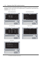
1) The designated values are written into the user-specified buffer memory by writing the
values from the monitor.
2) When changing the buffer memory data, input the numeric value using the auto display key
window and write it into the buffer memory.
(3) Special module monitor data can be allocated as user monitor screen data.
The special module monitor data installed in the computer can be allocated to serve as user
monitor screen data. To do this, the steps below are required.
1) Using the Copy function, allocate special module monitor data from another project as user
monitor screen data.
2) Correct the data to match the system used for the BM initial buffer memory number of the
Object function which has been set.
1-8
1.1 Features
1.1.4 Features of the special module monitor function
1
Features of the network monitor function
To use the network monitor function, you first must install an operating system (OS) for the network monitor
function on your GOT by using GT Designer2. This enables you to monitor the status of the MELSECNET/B,
MELSECNET (II), and MELSECNET/10 networks. The following describes the features of the network monitor function.
OVERVIEW
1.1.5
BEFORE BEGINNING OPERATION
2
3
SPECIFICATIONS
(1) Network monitor screens are selectable on the own station monitor screen to monitor the own
station and other stations on a network.
The own station monitor screen enables you to monitor the status of all the network lines
connected to the own station.
A touch of the screen will guide you through various monitor screens to monitor the status of the
own station and other stations on a network.
OPERATING LADDER MONITOR
5
6
OPERATING THE
VARIOUS LADDER
MONITOR SCREENS
(2) Network information can be obtained from the own station monitor screen.
Dedicated monitor screens are available for each category of station classification, depending on
the role that is played by the own station.
Network category: MELSECNET/B, MELSECNET (II) master station
MELSECNET/B, MELSECNET (II) local station
MELSECNET/10, MELSECNET/H control station/ordinary station
MELSECNET/10, MELSECNET/H remote master station
(Sample display) MELSECNET/B, MELSECNET (II) master station
OPERATING THE
UTILITY FUNCTION
4
ERROR MESSAGES
FOR LADDER MONITOR
7
OPERATING SYSTEM MONITOR
8
1.1 Features
1.1.5 Features of the network monitor function
1-9
(3) The status of other stations can be monitored on the other-station monitor screen.
The other-station monitor screen provides the following type of information on the status of other
stations connected on a network:
• Communications status of each station
• Data link status of each station
• Parameters status of each station
• CPU action status of each station
• CPU RUN status of each station
• Loop status of each station
(Sample display) Other station monitor menu screen
Other station's communications status monitor screen
1 - 10
1.1 Features
1.1.5 Features of the network monitor function
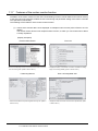
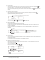
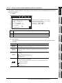
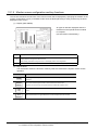
(1) Easy parameters and sequence program maintenance
Simple key operations allow checks, partial modifications, changes and additions of the parameters
and the sequence program in the PLC CPU.
Without peripheral equipment other than the GOT, the sequence program can be simply edited.
Example of command change in the sequence program
LD
OUT
LD
X0
Y20
X1
LD
X0
MOV D0
LD
X1
Change
3
D1
STEP : 12345/18374
K
MOV 1
D1
K
M999
187
D100
R 187
188
193
198
LD M999
List
MOVK1
D1
AND =K123 D100 EDITOR
MOVK1
D2
READ
INSERT
FROM
A
B
B
TO
C
D
D
PARAM
OTHER
INC
E
F
F
*
G
/
H
CALL
I
RET
J
DEC
K
MRD
L
MOV
M
>
N
<
O
P
P
_
Q
MPP
R
MPS
X
SHIFT WRITE DELETE
D1
D2
1
Exit
V
2
PLCRD.
D162
47
Mon.
D167
90
Menu
Print
Screen
D167 +
110
List
Cancel
Print
HELP
S
T
BCD
U
BIN
V
W
W
LD
C
AND
D
OR
E
MC
F
MCP
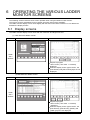
W
END
Z
LDI
8
ANI
9
ORI
A
MCR
B
Ý ’è
(
SET
4
ANB
5
ORB
6
PLS ƒ
N ƒ
Š ƒ
A
7
«
(¨ )
RST
0
SFT
1
CJ
2
OUT
3
GO
SP
5
OPERATING LADDER MONITOR
K
1234
=
4
OPERATING THE
UTILITY FUNCTION
(2) Interlock with the ladder monitor function (only when A985/97*/960GOT is used)
The list edit window can be started from the ladder monitor screen with a single touch. The list can
be edited while viewing the ladder.
The list can also be displayed from the step line displayed on the ladder monitor.
P0
2
BEFORE BEGINNING OPERATION
Installation of the List editor function OS into the memory with the GT Designer2 allows for list edit of the
sequence program in the ACPU.
The following shows features of the List editor function.
OVERVIEW
1
Features of the List editor function
SPECIFICATIONS
1.1.6
)
OPERATING THE
VARIOUS LADDER
MONITOR SCREENS
6
(3) The list edit screen can be recorded.
The hard copy function allows recording the edit screen of the list program.
(4) Access to other station is available.
The sequence program of the PLC CPU in other station can be list edited.
(5) Useful help functions
Help functions for read, write, insert and delete are available on the interactive menu selection
system. Simple operation is facilitated.
(6) Comment for each device can be displayed.
Comment of the device at the cursor position can be displayed.
9 OUT
M50
1 0 MOV
10
D1
Current value
8
OPERATING SYSTEM MONITOR
W
Comment of D1 is displayed.
1.1 Features
1.1.6 Features of the List editor function
ERROR MESSAGES
FOR LADDER MONITOR
7
1 - 11
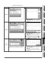
1.1.7
Features of the motion monitor function
Installation of the motion monitor function OS or downloading of motion monitor data into the built-in memory
of the GOT using GT Designer2 enables the servo monitoring and parameter setting of the motion controller
CPU (Q172CPU, Q173CPU).
The following are the features of the motion monitor function.
(1) Various servo monitor data can be displayed on multiple monitor screens (refer to Section 23.3 for
details)
The motion monitor function has multiple monitor screens, on which you can monitor servo data in
a variety of patterns.
(Display examples)
Present Value Monitor
• Monitors and displays the feed current values and actual current values of all running axes. (Refer to Section 23.3.3)
Error List
• Displays the history of errors that occurred on and after the leading
edge of PLC ready (M2000). (Refer to Section 23.3.3)
Positioning Monitor
Error List Designated-Axis
• Monitors the details of the positioning data set to any axis. (Refer to
• Displays the latest errors that occurred on the specified axis. (Refer
Section 23.3.5)
1 - 12
to Section 23.3.4)
1.1 Features
1.1.7 Features of the motion monitor function
Parameter setting screen
Parameter setting window appears
Parameter setting screen
OVERVIEW
1
(2) Servo parameters can be set by write operation (refer to Section 23.4 for details)
(Write example: Making the auto tuning function invalid)
BEFORE BEGINNING OPERATION
2
1) By performing write operation from the parameter setting screen, write the servo parameter
setting (basic parameters/adjustment parameters) to the motion controller CPU.
2) When changing any servo parameter setting, enter the necessary numeral or option number
from the automatically displayed key window to change the servo parameter setting, and
write it to the motion controller CPU.
3
SPECIFICATIONS
Parameter setting is
changed.
4
OPERATING THE
UTILITY FUNCTION
Change auto tuning from "1" to "2"
(No Auto).
OPERATING LADDER MONITOR
5
OPERATING THE
VARIOUS LADDER
MONITOR SCREENS
6
ERROR MESSAGES
FOR LADDER MONITOR
7
OPERATING SYSTEM MONITOR
8
1.1 Features
1.1.7 Features of the motion monitor function
1 - 13
1.1.8
Features of the servo amplifier monitor functions
You can perform various monitor functions, parameter setting changes, test operations and others for the
servo amplifier connected to the GOT.
The features of the servo amplifier monitor functions are described below.
(1) Servo amplifier status is displayed in real time
(detailed description: Section 26.4, Section 26.5)
The status and alarm definition of the servo amplifier connected to the GOT can be listed in real
time.
(Display example: A975GOT)
Monitor
• Lists the monitor data of the servo amplifier.
(Refer to Section 26.4.1.)
Alarm display
• Displays the definition (number, name, occurrence time, occurrence
factor) of the alarm currently occurring in the servo amplifier.
It also allows the alarm to be reset. (Refer to Section 26.4.2.)
(2) Various diagnostics can be run on the servo amplifier
(detailed description: Section 26.4.1)
There are multiple diagnostic functions to run various diagnostics on the connected servo amplifier.
(Display example)
DI/DO display
Amplifier information display
• Lists the ON/OFF states of the external I/O signals of the servo ampli-
• Displays the software number of the servo amplifier and the informa-
fier. (Refer to Section 26.6.1.)
tion (model, ID, encoder resolution) of the servo motor.
(Refer to Section 26.6.3.)
1 - 14
1.1 Features
1.1.8 Features of the servo amplifier monitor functions
1
OVERVIEW
(3) Servo parameters can be written (detailed description: Section 26.7)
The parameter values of the servo amplifier can be read, changed and written to the servo
amplifier.
BEFORE BEGINNING OPERATION
2
SPECIFICATIONS
3
(4) Various test operations can be performed (detailed description: Section 26.8)
Various test operations can be performed for the connected servo amplifier.
(Display example)
4
Motorless operation
OPERATING THE
UTILITY FUNCTION
JOG operation
OPERATING LADDER MONITOR
5
servo motor is not connected.
(Refer to Section 26.8.5.)
ERROR MESSAGES
FOR LADDER MONITOR
7
8
OPERATING SYSTEM MONITOR
(Refer to Section 26.8.3.)
• Simulates the operation of the servo motor in the servo amplifier if the
OPERATING THE
VARIOUS LADDER
MONITOR SCREENS
6
• While the Forward/Reverse key is touched, the servo amplifier runs.
1.1 Features
1.1.8 Features of the servo amplifier monitor functions
1 - 15
1.1.9
Features of the CNC monitor functions
Functions equivalent to the MELDAS dedicated display are available for the MELDAS connected with the
GOT, such as Position Display Monitor, Alarm Diagnosis Monitor, Tool Offset/Param, Program Monitor and
F0 function.
(detailed description: Section 29.2)
Position Display Monitor
Alarm Diagnosis Monitor
Tool Offset/Param
Program Monitor
F0 function
1 - 16
1.1 Features
1.1.9 Features of the CNC monitor functions
1
1.1.10 Features of the font change function
Standard font
OVERVIEW
This function changes the font displayed on the GOT monitor screen, utility and extended function.
(Details: Chapter 31)
Chinese (simplified characters) font
BEFORE BEGINNING OPERATION
2
This function switches the language for a system dialog displayed on the GOT monitor screen. (Details:
Chapter 32)
For the system dialog language switching function, extended function OS is not required to be installed in the
GOT.
Japanese
English
Chinese (simplified characters)
Chinese (traditional characters)
4
OPERATING THE
UTILITY FUNCTION
1.1.11 Features of the system dialog language switching function
SPECIFICATIONS
3
(2) When using Chinese (simplified characters) as system dialog language, it is recommended to set
Chinese (simplified characters) font for the character font with the font change function.
6
OPERATING THE
VARIOUS LADDER
MONITOR SCREENS
(1) The language switching is available for the following system dialogs.
1) System dialog displayed when using a monitor function
2) System dialog displayed when starting an extended function and the required extended function
OS is not installed
OPERATING LADDER MONITOR
5
ERROR MESSAGES
FOR LADDER MONITOR
7
OPERATING SYSTEM MONITOR
8
1.1 Features
1.1.10 Features of the font change function
1 - 17
2
BEFORE BEGINNING OPERATION
The required equipment for using the monitor functions in this manual is described in this section.
2.1 Before getting started with various functions
When using functions described in this manual, install the OS for each function into the GOT using GT
Designer2.
To install an OS for your desired function on your GOT, see GT Designer2 Version2 Operating Manual.
2.2 Precautions before use
(1) The usable functions change depending on the GOT.
Some functions require the memory board or compatible GOT depending on the model.
The following table indicates the functions available for the GOTs and whether or not the memory
board or compatible GOT is required.
: Required, ---: Not required,
Model
A985GOT(-V)
A97*GOT
Required device
A960GOT
A956WGOT
A95*GOT
--- M3 type GOT
Memory board
(A95*GOT-*BD-M3)
Utility function
---
---
---
---
---
System monitor function
---
---
---
---
---
Ladder monitor function
: No function
GT SoftGOT2
None
---
*2
*4
*4
Special module monitor function
*4
Network monitor function
*4
List editor function
*4
Motion monitor function
*3
Servo amplifier monitor function
*4
*4
CNC monitor function
*4
Font change function
*5
System dialog language switching function
---
*5
---
*5
---
*5
---
---
*1 The table below shows the models of memory boards available for using the option functions.
To use the ladder monitor function requires the memory board compatible with the PLC CPU to be monitored.
Name
Model
Contents
Memory board for
A9GT-FNB
For option function (applicable for MELSEC-A/FX ladder monitor)
option functions
A9GT-QFNB
For option function (applicable for MELSEC-Q/QnA/A/FX ladder monitor)
A9GT-FNB1M
Option function (applicable for MELSEC-A/FX ladder monitor) + internal memory extension 1MB
A9GT-FNB2M
Option function (applicable for MELSEC-A/FX ladder monitor) + internal memory extension 2MB
A9GT-FNB4M
Option function (applicable for MELSEC-A/FX ladder monitor) + internal memory extension 4MB
Expanded memory
board for option
functions
A9GT-FNB8M
Option function (applicable for MELSEC-A/FX ladder monitor) + internal memory extension 8MB
A9GT-QFNB4M
Option function (applicable for MELSEC-Q/QnA/A/FX ladder monitor) + internal memory extension 4MB
A9GT-QFNB8M
Option function (applicable for MELSEC-Q/QnA/A/FX ladder monitor) + internal memory extension 8MB
*2 Only MELSEC-Q ladder monitor may be used.
*3 Unusable for Present Value History Monitor.
*4 Use of the dedicated software allows the equivalent function to be performed.
*5 Use the A9GT-QFNB(
M). (The A9GT-FNB(
M) does not support the font change function.)
*6 When using the font change function, a memory card (4M bytes or more) is required.
2-1
2.1 Before getting started with various functions
BM
monitor
Monitoring of x points of current values
subsequent to specified buffer memory of Section
9.5
specified special module
Entry
monitor
Batch
monitor
System
monitor
function Data
editing
using
test
operation
Special module
monitor function
Network monitor
function
List editor function
Decimal and hexadecimal display of word
device values and buffer memory values
Monitoring of buffer memory of special
module on special screen
Monitoring of network status of
MELSECNET/B, (II) or /10
Sequence program in the ACPU is list
edited
Monitoring of servo-related items, such as
current values and positioning errors, on
various monitor screens
*10
*6
*9
*10
*9
*10
Setting/resetting of bit device
Device comment display
*6
*10
*5
*4
5
*10
*10
*10
*6
*10
*10
Section
9.1.2
*6
6
*10
Ch. 11
*11
Ch. 15
*10*11
OVERVIEW
4
*3
*10
Changing of current value for buffer
memory of word device
Section
Changing of current value for T/C (can be
9.6
used while monitoring T/C)
Changing of set value for T/C (can be
used while monitoring T/C)
of device values using quick
Section
Quick test Changing
test
9.6.2
Display
switching
*10
OPERATING LADDER MONITOR
Print out
3
*2
SPECIFICATIONS
T/C
monitor
Display
Ladder switching
monitor
function Device
changing
*1
OPERATING THE
UTILITY FUNCTION
Ch. 4
Sequence program monitoring using
Section
ladder signals
6.3.1
Decimal and hexadecimal display of word
Section
device values
6.3.3
Device comment display
Section
Changing of device values
6.3.5
Section
Printing of ladder
6.3.6
Monitoring of current values by
Section
pre-registering monitor devices
9.2
Monitoring of n points of current values
Section
subsequent to specified device
9.3
Monitoring of m points of current values, Section
set values, contact points, and coils
9.4
subsequent to specified device
*11
*11
*11
Ch. 19
Servo
Motion monitor
monitor
function Parameter
Changing of servo parameter values
setting
Ch. 22
Servo amplifier
monitor function
Servo amplifier monitor, servo parameter
setting change, test operation
Can be used independently of the connection form since the RS-232C
Ch. 25 interface of the GOT is used. (Refer to Section 3.7.3 for the precautions on
the servo amplifier monitor function.)
CNC monitor
function
Font change
function
System dialog
language
switching function
Monitor and parameter change of
MELDAS C6/C64
Ch. 28
Changing the font displayed on GOT
Ch. 31 Can be used independently of the connection form.
Changing the language displayed on GOT
system dialogs
Ch. 32 Can be used independently of the connection form.
*8
OPERATING THE
VARIOUS LADDER
MONITOR SCREENS
Ladder
monitor
7
*1 Clock setting cannot be used when the A7GT-J71LP23 or A7GT-J71BR13 is used, and the GOT is connected to the
Q00JCPU, Q00CPU or Q01CPU.
*2 Clock setting cannot be used when the A8GT-J61BT15 is used (remote device station).
*3 When the A8GT-J61BT15 is used (in the remote device station), only the link devices assigned to the GOT can be
monitored.
*4 The T/C set values cannot be monitored if the software version of the A8GT-J61BT13 used is version W or earlier.
*5 Cannot change V or Z current values.
2.2 Precautions before use
2-2
ERROR MESSAGES
FOR LADDER MONITOR
Utility function
QCPU(Q Mode)
ComMELSEC
CC-Link
Etherputer
NET connection
connection
net
link
concon10
B, II BT13 BT15 G4
nection H
nection
2
8
OPERATING SYSTEM MONITOR
Functions
CPU
Ref.
Bus
direct
Section conconnection
nection
1
BEFORE BEGINNING OPERATION
(2) Note that some functions are unavailable depending on the connection target CPU and connection
form. There are the following restrictions on each function depending on the connection target CPU
and connection form.
Refer to Chapter 2 of the GOT-A900 Series User's Manual (Connection System Manual) for the
connectable CPU names and the access range for monitoring per connection form.
(a) Connection with QCPU (Q mode)
BT13 : Indicates that the A8GT-J61BT13 is used (intelligent device station).
BT15 : Indicates that the A8GT-J61BT15 is used (remote device station).
G4
: Indicates that the A9GT-RS4 or A9GT-50WRS4 is used (via G4).
: Usable
: Partly restricted
: Unusable
*6 Cannot be monitored if the software version of the A8GT-J61BT13 used is version W or earlier.
*7 If you modified the set value for T/C using the ladder monitor test function, you need to repeat the PC readout procedure to enable the display of the modification.
*8 The target CPUs of the motion monitor function are only the Q172CPU and Q173CPU.
*9 Cannot be monitored when the Q172CPU or Q173CPU is monitored.
*10 The following conditions must be satisfied to perform monitoring when connected to MELSECNET/10.
(1) GOT
Communication unit: A9GT-QJ71LP23, A9GT-QJ71BR13
Communication driver: MNET/10 (A/QnA/Q)
(2) QCPU or network module (QJ71LP21, QJ71LP21-25, QJ71LP21S-25, QJ71LP21G, QJ71BR11) to be monitored
The function version should be version B or later.
*11 Q12PRHCPU and Q25PRHCPU cannot be monitored.
2-3
2.2 Precautions before use
: Partly restricted
: Unusable
QnACPU
H
10
B, II BT13 BT15
Decimal and hexadecimal display of word
Section
device values
6.3.3
Device comment display
Device
changing
Changing of device values
Section
6.3.5
Print out
Printing of ladder
Section
6.3.6
Entry
monitor
Monitoring of current values by
pre-registering monitor devices
Section
9.2
Batch
monitor
Monitoring of n points of current values
subsequent to specified device
Section
9.3
T/C
monitor
Monitoring of m points of current values,
set values, contact points, and coils
subsequent to specified device
Section
9.4
BM
monitor
Monitoring of x points of current values
subsequent to specified buffer memory of Section
9.5
specified special module
G4
*1
Section
6.3.1
*6
3
*6
*6
*2
4
*6
Setting/resetting of bit device
Changing of current value for buffer
memory of word device
*4
Section
Changing of current value for T/C (can be
9.6
used while monitoring T/C)
Changing of set value for T/C (can be
used while monitoring T/C)
of device values using quick
Quick test Changing
test
2
SPECIFICATIONS
Display
switching
CC-Link
connection
OPERATING THE
UTILITY FUNCTION
Sequence program monitoring using ladder signals
Display
switching
MELSEC
NET connection
Ch. 4
Ladder
monitor
System
monitor
function Data
editing
using
test
operation
ComEtherputer
net
link
conconnection
nection
*6
5
*6
*6
Section
9.6.2
Device comment display
Section
Decimal and hexadecimal display of word 9.1.2
device values and buffer memory values
OPERATING LADDER MONITOR
Ladder
monitor
function
CPU
Bus
direct
conconnection
nection
*6
*6
*6
Special module
monitor function
Monitoring of buffer memory of special
module on special screen
Ch. 11
*6
Network monitor
function
Monitoring of network status of
MELSECNET/B, (II) or /10
Ch. 15
*6
List editor function
Sequence program in the ACPU is list
edited
Ch. 19
Servo
Motion monitor
monitor
function Parameter
setting
Monitoring of servo-related items, such as
current values and positioning errors, on
various monitor screens
Ch. 22
Changing of servo parameter values
Servo amplifier
monitor function
Servo amplifier monitor, servo parameter
setting change, test operation
Can be used independently of the connection form since the RS-232C
Ch. 25 interface of the GOT is used. (Refer to Section 3.7.3 for the precautions on
the servo amplifier monitor function.)
CNC monitor
function
Monitor and parameter change of
MELDAS C6/C64
Ch. 28
Font change
function
Changing the font displayed on GOT
Ch. 31 Can be used independently of the connection form.
System dialog
language
switching function
Changing the language displayed on GOT
system dialogs
Ch. 32 Can be used independently of the connection form.
OPERATING THE
VARIOUS LADDER
MONITOR SCREENS
6
8
*1 Clock setting cannot be used when the A8GT-J61BT15 is used (remote device station).
*2 When the A8GT-J61BT15 is used (in the remote device station), only the link devices assigned to the GOT can be
monitored.
*3 Cannot monitor T/C set values.
*4 Cannot change V or Z current values.
2.2 Precautions before use
7
ERROR MESSAGES
FOR LADDER MONITOR
Utility function
Ref.
Section
2-4
OPERATING SYSTEM MONITOR
Functions
BEFORE BEGINNING OPERATION
: Usable
OVERVIEW
1
(b) Connection with QnACPU
BT13 : Indicates that the A8GT-J61BT13 is used (intelligent device station)
BT15 : Indicates that the A8GT-J61BT15 is used (remote device station).
G4
: Indicates that the A9GT-RS4 or A9GT-50WRS4 is used (via G4).
*5 If you modified the set value for T/C using the ladder monitor test function, you need to repeat the PC readout procedure to enable the display of the modification.
*6 The following conditions must be satisfied to perform monitoring when connected to MELSECNET/10.
(1) GOT
Communication unit: A9GT-QJ71LP23, A9GT-QJ71BR13
Communication driver: MNET/10 (A/QnA/Q)
(2) QCPU or network module (QJ71LP21, QJ71LP21-25, QJ71LP21S-25, QJ71LP21G, QJ71BR11) to be monitored
The function version should be version B or later.
2-5
2.2 Precautions before use
: Partly restricted
: Unusable
ACPU/QCPU (A mode)
10
B, II BT13 BT15
Device comment display
G4
*2
*1
Section
6.3.3
Print out
Printing of ladder
Section
6.3.6
Entry
monitor
Monitoring of current values by
pre-registering monitor devices
Section
9.2
Batch
monitor
Monitoring of n points of current values
subsequent to specified device
Section
9.3
T/C
monitor
Monitoring of m points of current values,
set values, contact points, and coils
subsequent to specified device
Section
9.4
BM
monitor
Monitoring of x points of current values
subsequent to specified buffer memory of
specified special module
Section
9.5
3
*3
4
Setting/resetting of bit device
Changing of current value for buffer
memory of word device
Changing of current value for T/C (can be
used while monitoring T/C)
*5
Section
9.6
5
Changing of set value for T/C (can be
used while monitoring T/C)
of device values using quick
Quick test Changing
test
Device comment display
Decimal and hexadecimal display of word
device values and buffer memory values
Section
9.6.2
Section
9.1.2
Special module
monitor function
Monitoring of buffer memory of special
module on special screen
Ch. 11
Network monitor
function
Monitoring of network status of
MELSECNET/B, (II) or /10
Ch. 15
List editor function
Sequence program in the ACPU is list
edited
Ch. 19
Servo
Motion monitor
monitor
function Parameter
setting
Monitoring of servo-related items, such as
current values and positioning errors, on
various monitor screens
Ch. 22
Changing of servo parameter values
Servo amplifier
monitor function
Servo amplifier monitor, servo parameter
setting change, test operation
CNC monitor
function
Monitor and parameter change of
MELDAS C6/C64
Ch. 28
Font change
function
Changing the font displayed on GOT
Ch. 31
Can be used independently of the connection form.
Ch. 32
Can be used independently of the connection form.
6
*7
*8
Can be used independently of the connection form since the RS-232C
interface of the GOT is used. (Refer to Section 3.7.3 for the precautions
on the servo amplifier monitor function.)
System dialog
the language displayed on GOT
language switching Changing
system dialogs
function
7
ERROR MESSAGES
FOR LADDER MONITOR
Ch. 25
2
SPECIFICATIONS
Decimal and hexadecimal display of word
device values
CC-Link connection
Section
6.3.1
Section
6.3.5
Display
switching
H
Ch. 4
Sequence program monitoring using
ladder signals
Changing of device values
System
monitor
function Data
editing
using
test
operation
MELSEC
NET connection
OPERATING LADDER MONITOR
Display
Ladder switching
monitor
function
Device
changing
ComEtherputer
net
link
conconnection
nection
8
*1 Subprograms 2, 3 of the A4UCPU (for computer link connection) cannot be monitored.
*2 Can be monitored only when the A8GT-J61BT15 is used (in the remote device station).
*3 When the A8GT-J61BT15 is used (in the remote device station), only the link devices assigned to the GOT can be
monitored.
2.2 Precautions before use
2-6
OPERATING SYSTEM MONITOR
Ladder
monitor
CPU
Bus
direct
conconnection
nection
OPERATING THE
UTILITY FUNCTION
Utility function
Ref. Section
OPERATING THE
VARIOUS LADDER
MONITOR SCREENS
Functions
BEFORE BEGINNING OPERATION
: Usable
OVERVIEW
1
(c) Connection with ACPU/QCPU (A mode)
BT13 : Indicates that the A8GT-J61BT13 is used (intelligent device station).
BT15 : Indicates that the A8GT-J61BT15 is used (remote device station).
G4
: Indicates that the A9GT-RS4 or A9GT-50WRS4 is used (via G4).
*4 Cannot monitor T/C set values.
*5 Cannot change V or Z current values.
*6 If you modified the set value for T/C using the ladder monitor test function, you need to repeat the PC readout procedure to enable the display of the modification.
*7 Monitor is disabled when the connection target CPU is the AnU type (MELSECNET/10 network card is fitted).
*8 If ACPU is performing E2PROM operation when connected to the GOT, program write is disabled.
2-7
2.2 Precautions before use
1
(d) Connection with FXCPU, third party PLC or microcomputer
Functions
Utility function
Ladder
monitor
Sequence program monitoring using ladder signals
CPU direct connection
*1
: Partly restricted
Other PLC
connection
: Unusable
Microcomputer
connection
*2
*3
Section
6.3.1
2
Decimal and hexadecimal display of word
Section
device values
6.3.3
Device comment display
Changing of device values
Section
6.3.5
Print out
Printing of ladder
Section
6.3.6
Entry
monitor
Monitoring of current values by
pre-registering monitor devices
Section
9.2
BEFORE BEGINNING OPERATION
Display
Ladder switching
monitor
function
Device
changing
Ch. 4
FXCPU *5
OVERVIEW
: Usable
Ref.
Section
Batch
monitor
Monitoring of n points of current values
subsequent to specified device
Section
9.3
3
T/C
monitor
Monitoring of m points of current values,
set values, contact points, and coils subsequent to specified device
Section
9.4
BM
monitor
Monitoring of x points of current values
subsequent to specified buffer memory of Section
9.5
specified special module
Changing of current value for T/C (can be
used while monitoring T/C)
SPECIFICATIONS
4
Section
9.6.2
Section
9.1.2
5
Changing of set value for T/C (can be
used while monitoring T/C)
of device values using quick
Quick test Changing
test
Display
switching
Section
9.6
Device comment display
Decimal and hexadecimal display of word
device values and buffer memory values
Monitoring of buffer memory of special
module on special screen
Ch. 11
Network monitor
function
Monitoring of network status of
MELSECNET/B, (II) or /10
Ch. 15
List editor function
Sequence program in the ACPU is list
edited
Ch. 19
Servo
Motion monitor
monitor
function Parameter
setting
Monitoring of servo-related items, such as
current values and positioning errors, on
various monitor screens
Ch. 22
Servo amplifier
monitor function
Servo amplifier monitor, servo parameter
setting change, test operation
Can be used independently of the connection form since the RS-232C
Ch. 25 interface of the GOT is used. (Refer to Section 3.7.3 for the precautions on
the servo amplifier monitor function.)
CNC monitor
function
Monitor and parameter change of
MELDAS C6/C64
Ch. 28
Font change
function
Changing the font displayed on GOT
Ch. 31 Can be used independently of the connection form.
System dialog
language
switching function
Changing the language displayed on GOT
system dialogs
Ch. 32 Can be used independently of the connection form.
OPERATING LADDER MONITOR
Special module
monitor function
Changing of servo parameter values
*1 Clock setting cannot be made when the GOT is connected with the PLC CPU that does not have the clock function
(FX0, FX0N, FX1, FX2NC, FX0S).
The FX2 and FX2C allow clock setting to be made only when the cassette for real-time clock is used.
*2 Clock setting cannot be made when the GOT is connected with the PLC CPU that does not have the clock function.
6
OPERATING THE
VARIOUS LADDER
MONITOR SCREENS
Changing of current value for buffer
memory of word device
OPERATING THE
UTILITY FUNCTION
Setting/resetting of bit device
7
ERROR MESSAGES
FOR LADDER MONITOR
System
monitor
function Data
editing
using
test
operation
*4
OPERATING SYSTEM MONITOR
8
2.2 Precautions before use
2-8
*3 You can set the clock function only when you are using A9GT-RS2T, which includes a clock element.
*4 T/C set values and coils cannot be monitored.
*5 The FX3UC series can be monitored only in the device range of FX2N series.
2-9
2.2 Precautions before use
: Partly restricted
: Unusable
QCPU(Q Mode)
Utility function
Display
Ladder switching
monitor
function
Device
changing
CPU
Bus
direct
conconnection
nection
ComEtherputer
net
link
conconnection
nection
MELSEC
NET connection
H
10
B, II BT13 BT15
Ch. 4
Sequence program monitoring using ladder signals
CC-Link connection
*1
Section
6.3.1
Decimal and hexadecimal display of word
Section
device values
6.3.3
Device comment display
3
Changing of device values
Section
6.3.5
Print out
Printing of ladder
Section
6.3.6
Entry
monitor
Monitoring of current values by
pre-registering monitor devices
Section
9.2
*2
Batch
monitor
Monitoring of n points of current values
subsequent to specified device
Section
9.3
*2
T/C
monitor
Monitoring of m points of current values,
set values, contact points, and coils
subsequent to specified device
Section
9.4
BM
monitor
Monitoring of x points of current values
subsequent to specified buffer memory of Section
9.5
specified special module
4
OPERATING THE
UTILITY FUNCTION
System
monitor
function Data editing using
test operation
G4
Setting/resetting of bit device
Changing of current value for buffer
memory of word device
Changing of current value for T/C (can be
used while monitoring T/C)
Section
9.6
5
Display
switching
Device comment display
Decimal and hexadecimal display of word
device values and buffer memory values
OPERATING LADDER MONITOR
Changing of set value for T/C (can be
used while monitoring T/C)
of device values using quick
Quick test Changing
test
2
SPECIFICATIONS
Ladder
monitor
Ref.
Section
Section
9.6.2
Section
9.1.2
Special module
monitor function
Monitoring of buffer memory of special
module on special screen
Ch. 11
Network monitor
function
Monitoring of network status of
MELSECNET/B, (II) or /10
Ch. 15
List editor function
Sequence program in the ACPU is list
edited
Ch. 19
Servo
Motion monitor
monitor
function Parameter
setting
Monitoring of servo-related items, such as
current values and positioning errors, on
various monitor screens
Ch. 22
Servo amplifier
monitor function
Servo amplifier monitor, servo parameter
setting change, test operation
Can be used independently of the connection form since the RS-232C
Ch. 25 interface of the GOT is used. (Refer to Section 3.7.3 for the precautions on
the servo amplifier monitor function.)
CNC monitor
function
Monitor and parameter change of
MELDAS C6/C64
Ch. 28
Font change
function
Changing the font displayed on GOT
Ch. 31 Can be used independently of the connection form.
System dialog
language
switching function
Changing the language displayed on GOT
system dialogs
Ch. 32 Can be used independently of the connection form.
OPERATING THE
VARIOUS LADDER
MONITOR SCREENS
6
Changing of servo parameter values
*3
7
ERROR MESSAGES
FOR LADDER MONITOR
Functions
BEFORE BEGINNING OPERATION
: Usable
OVERVIEW
1
(e) Connection with MELDAS C6/C64
BT13 : Indicates that the A8GT-J61BT13 is used (intelligent device station).
BT15 : Indicates that the A8GT-J61BT15 is used (remote device station).
G4
: Indicates that the A9GT-RS4 or A9GT-50WRS4 is used (via G4).
OPERATING SYSTEM MONITOR
8
2.2 Precautions before use
2 - 10
*1 Clock setting cannot be used.
*2 Only the link devices assigned to the GOT can be monitored.
*3 The following conditions must be satisfied to perform monitoring when connected to MELSECNET/10.
(1) GOT
Communication unit: A9GT-QJ71LP23, A9GT-QJ71BR13
Communication driver: MNET/10 (A/QnA/Q)
(2) QCPU or network module (QJ71LP21, QJ71LP21-25, QJ71LP21S-25, QJ71LP21G, QJ71BR11) to be
monitored
The function version should be version B or later.
2 - 11
2.2 Precautions before use
: Partly restricted
: Unusable
MLSECNET/H system remote I/O station
Functions
Ref.
Section
ComCPU
Etherputer
direct
net
Bus
link
conconconconnection nection nection nection
MELSEC
NET connection
H
Sequence program monitoring using
ladder signals
Display
switching
Decimal and hexadecimal display of word
device values
Section
6.3.3
Device comment display
Device
changing
Changing of device values
Section
6.3.5
Print out
Printing of ladder
Section
6.3.6
Entry
monitor
Monitoring of current values by
pre-registering monitor devices
Section
9.2
Batch
monitor
Monitoring of n points of current values
subsequent to specified device
Section
9.3
T/C
monitor
Monitoring of m points of current values,
set values, contact points, and coils
subsequent to specified device
Section
9.4
BM
monitor
Monitoring of x points of current values
subsequent to specified buffer memory of Section
9.5
specified special module
System
monitor
function Data
editing
using
test
operation
10
B, II BT13 BT15
G4
*1
Section
6.3.1
3
SPECIFICATIONS
Ladder
monitor
*1
4
Setting/resetting of bit device
Changing of current value for buffer
memory of word device
5
*2
Section
9.6
Changing of current value for T/C (can be
used while monitoring T/C)
OPERATING LADDER MONITOR
Ladder
monitor
function
Ch. 4
Changing of set value for T/C (can be
used while monitoring T/C)
Display
switching
Device comment display
Decimal and hexadecimal display of word
device values and buffer memory values
Section
9.6.2
Section
9.1.2
6
OPERATING THE
VARIOUS LADDER
MONITOR SCREENS
of device values using quick
Quick test Changing
test
2
OPERATING THE
UTILITY FUNCTION
Utility function
CC-Link connection
BEFORE BEGINNING OPERATION
: Usable
OVERVIEW
1
Connection with MELSECNET/H system remote I/O station
BT13 : Indicates that the A8GT-J61BT13 is used (intelligent device station).
BT15 : Indicates that the A8GT-J61BT15 is used (remote device station).
G4
: Indicates that the A9GT-RS4 or A9GT-50WRS4 is used (via G4).
Special module
monitor function
Monitoring of buffer memory of special
module on special screen
Ch. 11
Network monitor
function
Monitoring of network status of
MELSECNET/B, (II) or /10
Ch. 15
List editor function
Sequence program in the ACPU is list
edited
Ch. 19
Servo
Motion monitor
monitor
function Parameter
setting
Monitoring of servo-related items, such as
current values and positioning errors, on
various monitor screens
Ch. 22
Servo amplifier
monitor function
Servo amplifier monitor, servo parameter
setting change, test operation
Can be used independently of the connection form since the RS-232C
Ch. 25 interface of the GOT is used. (Refer to Section 3.7.3 for the precautions on
the servo amplifier monitor function.)
CNC monitor
function
Monitor and parameter change of
MELDAS C6/C64
Ch. 28
Font change
function
Changing the font displayed on GOT
Ch. 31 Can be used independently of the connection form.
System dialog
language
switching function
Changing the language displayed on GOT
system dialogs
Ch. 32 Can be used independently of the connection form.
7
Changing of servo parameter values
ERROR MESSAGES
FOR LADDER MONITOR
(f)
OPERATING SYSTEM MONITOR
8
2.2 Precautions before use
2 - 12
*1 The clock setting screen is displayed, but the date and time cannot be set. To set the date and time on PLC CPU
master station, set the clock using GX Developer.
*2 Cannot change V or Z current value.
2 - 13
2.2 Precautions before use
MELSEC-A ladder monitor
---
1
*1
2
Only one may be
MELSEC-Q ladder monitor *1
2
installed.
MELSEC-FX ladder monitor
1
Ladder
MELSEC-QnA ladder monitor
monitor
*1
2
Only one may be
2
installed
Special module, recipe, sound
1
---
Network monitor
1
---
2
---
2
---
2
---
List editor (MELSEC-A)
Gateway
*1
Servo amplifier Monitor
Others
*1
*1
ESC printer, bar code, report, CSV file, external key input
1
PCL printer, bar code, report, CSV file, external key input
1
4
ESC printer, bar code, report, CSV file, proximity I/O
1
PCL printer, bar code, report, CSV file, proximity I/O
1
ESC printer, bar code, report, CSV file, video/RGB input
1
PCL printer, bar code, report, CSV file, video/RGB input
1
Only one may be
Chinese (Big 5) printer, bar code, report, CSV file, external key input
1
installed.
Chinese (Big 5) printer, bar code, report, CSV file, proximity I/O
1
Chinese (Big 5) printer, bar code, report, CSV file, video/RGB input
1
Chinese (GB) printer, bar code, report, CSV file, external key input
1
Chinese (GB) printer, bar code, report, CSV file, proximity I/O
1
Chinese (GB) printer, bar code, report, CSV file, video/RGB input
1
5
6
*1 When installed into the GOT, this OS uses the memory space twice larger than that of the other extended function
OS.
*2 Install the "Other" extended function OSs when using the following functions.
Report function
Operation panel function
Printer function
Barcode function
Video display function
RGB display
External I/O function
When object function is used to create CSV format files
For this extended function OS, refer to the following 1) and 2) and select the OS that meets the language to be
output to the printer or CSV file and the optional device used.
1) Language to be output to the printer connected to the GOT or the CSV file (alarm history display function, recipe
function)
ESC printer
: Output in Japanese
PCL printer
: Output in English
Chinese (Big 5) printer : Output in Chinese (traditional language)
Chinese (GB) printer
7
8
: Output in Chinese (simplified language)
2) Used optional device
OPERATING SYSTEM MONITOR
CNC monitor
*1
OPERATING THE
UTILITY FUNCTION
Motion monitor
3
SPECIFICATIONS
1
OPERATING LADDER MONITOR
System monitor
Remarks
OPERATING THE
VARIOUS LADDER
MONITOR SCREENS
Terms of Memory Count
ERROR MESSAGES
FOR LADDER MONITOR
Space Necessary for Installation in
BEFORE BEGINNING OPERATION
2
(a) List of extended function and option function OSs installed
Expanded Function OS Name
1
OVERVIEW
(3) If a system program (OS) for the expanded or option functions has been installed, the following
space is required in the GOT built-in internal memory to store user-created monitor screen data.
Hence, add the memory board as required.
Hence, installing the extended function OS into the GOT decreases the memory space (for monitor
screen data storage) available for the user.
If the free space is insufficient, fit the extension memory board to increase the memory space.
External key input : Operation panel, ten-key panel (operation panel function)
Proximity I/O
: External I/O device (external I/O function)
Video/RGB input
: Video camera (video display function), personal computer (RGB display function)
2.2 Precautions before use
2 - 14
(b) Number of extended function OSs installed and free space of GOT's built-in memory
Number of Extended functions OSs
Memory Space Used [k bytes]
Free Space (User area) [k bytes] *1
0
0
1152
1
256
896
2
384
768
3
640
512
4
768
384
5
1024
128
6
1152
0
*1 Since the A95*GOT-*BD-M3 has the built-in memory of 3200k bytes, the free space is the above value plus 2048k
bytes.
Using the special module monitor/motion monitor/servo amplifier monitor function
requires the built-in memory to have enough memory space to store the special
module monitoring data/motion monitor, servo amplifier monitor screens. (Refer to
Section 3.3.3, 3.6.4 and 3.7.5.)
2 - 15
2.2 Precautions before use
In this chapter, the specifications of the ladder monitor function, system monitor function, special module
monitor function, list editor function, motion monitor function, servo amplifier monitor and CNC monitor are
explained separately.
Refer to Section 2.2 for restrictions on the ladder monitor function.
PLC CPUs to be monitored
The PLC CPUs that allow ladder monitoring are the QCPU, QnACPU, ACPU, FXCPU, motion controller
CPU (Except Q172CPU and Q173CPU) and MELDAS C6/C64. For details, refer to Section 2.2 (2).
For access range for the ladder monitor function, see GOT-A900 Series User’s manual (Connection system
manual).
• When the capacity of parameter, PLC program, TC setting value, comment and
extension comment is 144 k bytes or more, the comment will not be properly
displayed.
• The local device cannot be monitored on the QCPU(Q mode), QnACPU.
3.1.3
Precautions when using the ladder monitor function
OPERATING THE
UTILITY FUNCTION
4
Access ranges to be monitored
5
OPERATING LADDER MONITOR
3.1.2
SPECIFICATIONS
3
6
(1) When using the ladder monitor function during monitor of the MELDAS C6/C64, install the
MELSEC-QnA ladder monitoring OS into the GOT.
(2) Changing to the Chinese (simplified characters) font makes the MELSEC-Q/QnA ladder monitor
function unusable.
For specifications of the font change function, refer to Section 3.9.
OPERATING THE
VARIOUS LADDER
MONITOR SCREENS
3.1.1
2
BEFORE BEGINNING OPERATION
3.1 Ladder monitor function specifications
OVERVIEW
SPECIFICATIONS
7
ERROR MESSAGES
FOR LADDER MONITOR
3
1
OPERATING SYSTEM MONITOR
8
3.1 Ladder monitor function specifications
3.1.1 PLC CPUs to be monitored
3-1
3.2 System monitor function specifications
Refer to Section 2.2 for restrictions on the system monitor function.
3.2.1
PLC CPUs to be monitored
The PLC CPUs that allow system monitoring are the QCPU, QnACPU, ACPU, FXCPU, motion controller
CPU and MELDAS C6/C64. For details, refer to Section 2.2 (2).
3.2.2
Access ranges to be monitored
For access range for the system monitor function, see GOT-A900 Series User’s manual (Connection System
Manual).
3.2.3
Names of devices to be monitored
For the names of devices that can be monitored with the system monitor function, see GT Designer2
Version1 Reference Manual.
3.2.4
Precautions when using the system monitor function
The precautions to follow when using the system monitor function are shown below.
(1) Monitor and test of real number data
Real number data cannot be monitored or tested.
Monitoring of word devices that save real number data is all done by integer data (binary data).
(2) Monitoring in 32-bit modules
When monitoring word devices (such as T, C, D, W) in 32-bit (2-word) modules, monitor up to the
point where 32 bits remain in the monitor processing. A location where 16 bits (1 word) remain
cannot be monitored.
This situation occurs when an odd number has been specified as the initial number in the monitor
device.
Example: When monitoring the A2NCPU data register in 32-bit modules beginning with an odd
number (D1, D3...)
1017
1018
1019
1020
1021
Monitor display module
3-2
3.2 System monitor function specifications
3.2.1 PLC CPUs to be monitored
1022
1023
Nothing displayed
<Viewing the Rated Plate>
1
OVERVIEW
(3) The "Date" column of a Rated Plate shows the date manufactured and function version number. If it
reads "9707 B" or a later notation, timer/counter settings can be changed and device comments
can be displayed when using any of the large-scale QnACPUs or small-scale QnACPUs.
When changing the timer/counter setup value and performing the device comment display, use the
CPU that is described above.
BEFORE BEGINNING OPERATION
2
PROGRAMMBLE CONTROLLER
3
SPECIFICATIONS
DATE 9707 B
Date of
Function
manufacture version
3.3 Special module monitor function specifications
5
OPERATING LADDER MONITOR
(5) When executing multiple programs with the QCPU (Q mode) and QnACPU, setting values of timer/
counter can be changed only to the program (scan execution type program set at the lowest
number among them in parameter settings of GX Developer) whose file name is displayed on the
TC Monitor screen.
Note that a file to be displayed cannot be changed on the GOT.
Refer to Section 9.4.2 for details.
OPERATING THE
UTILITY FUNCTION
4
(4) Only the main program may be used to change the timer/counter set values on the AnNCPU,
AnACPU and AnUCPU.
OPERATING THE
VARIOUS LADDER
MONITOR SCREENS
6
Refer to Section 2.2 for restrictions on the special unit monitor.
ERROR MESSAGES
FOR LADDER MONITOR
7
OPERATING SYSTEM MONITOR
8
3.3 Special module monitor function specifications
3.2.4 Precautions when using the system monitor function
3-3
3.3.1
Access ranges to be monitored
(1) When using bus connection/CPU direct connection/computer link connection
• The special function modules on the bases of the connected station and other stations can be
monitored.
• Special module monitoring for computer link connection is enabled for the systems of the
following combinations.
PLC CPU used
Computer link/serial communication module used
QCPU (Q mode)
QJ71C24
(Except redundant system)
QCPU (A mode)
A1SJ71UC24
QnACPU
AJ71QC24, A1SJ71QC24
ACPU
AJ71UC24, A1SJ71UC24
*1 For details of module name, refer to GOT-A900 series user’s manual (Connection System Manual)
(2) When using MELSECNET(II) connection/MELSECNET/B connection
• The special function module on the base of the master station can be monitored.(Cannot be
monitored when the master station is the QnACPU.)
• The special function modules on the bases of local stations/remote I/O station cannot be
monitored.
(3) When using MELSECNET/10 connection
• The special function modules on the bases of the control station and normal stations can be
monitored.
When the QCPU (Q mode)/QnACPU is used for the control/normal station, it cannot be
monitored depending on the communication unit.
Communication unit
Applicable CPU of the control/normal station
A7GT-J71LP23, A7GT-J71BR13
ACPU, QCPU (A mode)
A9GT-QJ71LP23, A9GT-QJ71BR13
ACPU, QCPU (A mode), QnACPU, QCPU (Q mode)
• The special function module cannot be monitored when it is mounted on the base of remote I/O
station.
(4) When using CC-Link connection (remote device station)
• The special function modules cannot be monitored.
(5) When using CC-Link connection (intelligent device station / via G4)
• The special function modules on the bases of the master and local stations can be monitored.
• The special function module cannot be monitored when it is mounted on the base of remote I/O
station.
(6) When using Ethernet connection
The special function module on the base of the PLC CPU assigned the IP address can be
monitored.
(The station assigned in the Ethernet setting of GT Designer2 can be monitored.)
3.3.2
Special function modules to be monitored
The modules for which special function monitoring can be done are only those types shown in Section 3.3.3.
Monitoring of special function modules other than those can be done with the system monitor function "BM
Monitor".
3-4
3.3 Special module monitor function specifications
3.3.1 Access ranges to be monitored
1
Memory capacity
The following table indicates memory spaces for special module monitor data.
The memory spaces required for storing data into the internal memory of the GOT is the same as the memory spaces required for storing data into the hard disk of a personal computer.
Special module monitor data common
information
14.5
Q64AD
AD61
8.14
Q68ADV
A62DA-S1
6.91
Q68ADI
A62LS
69.8
Q62DA
A68AD(S2)
9.97
Q64DA
QD62
17.8
A68RD4
A616AD
123
A616DAI
33.5
A616DAV
3
12.9
*3
QD62E
16.2
QD62D
QD75P
QD75D
QD75M
313.5
4
473.8
OPERATING THE
UTILITY FUNCTION
A68RD3
18.2
A616TD
230
Input module
0.0
AD70
20.5
Output module
0.0
AD70D
29.3
---
---
AD71(S1/S2/S7)
546
---
---
---
---
---
---
---
---
---
---
---
---
---
---
---
---
AD72
562
A1SD71-S2(S7)
AD75P1(P2/P3) *1
A1SD75P1(P2/P3)
*2
AJ71PT32-S3
520 *3
43.5
AJ71ID1(ID2)-R4
A1SJ71ID1(ID2)-R4
40.5
A84AD
20.2
---
---
A1SD61
36.9
---
---
A1S62DA
5.12
---
---
A1S62RD
12.5
---
---
A1S63ADA
16.4
---
---
A1S64AD
12.3
---
---
A1S68AD
9.75
---
---
---
---
A1S68DAI
25.8*3
A1S68DAV
---
---
A1SD70
21.1
---
---
A1SJ71JP132-S3
43.2
---
---
A1S64TCTT/RT-S1
45.7
---
---
Input module
0.0
---
---
Output module
0.0
---
---
5
OPERATING LADDER MONITOR
15
13.4
SPECIFICATIONS
13.4
A61LS
A68ADN
2
Memory space [k bytes]
6
OPERATING THE
VARIOUS LADDER
MONITOR SCREENS
information
Stored data
7
ERROR MESSAGES
FOR LADDER MONITOR
Special module monitor data common
Memory space [k bytes]
8
OPERATING SYSTEM MONITOR
Stored data
For QCPU(Q mode)
BEFORE BEGINNING OPERATION
For QCPU(A mode), QnACPU, ACPU
OVERVIEW
3.3.3
*1: The AD75M1(M2/M3) can be monitored within the range of the AD75P1(P2/P3).
*2: The A1SD75M1(M2/M3) can be monitored within the range of the A1SD75P1(P2/P3).
*3: Downloading either data enables both special function modules to be monitored.
3.3 Special module monitor function specifications
3.3.3 Memory capacity
3-5
3.3.4
Precautions when using the special module monitor function
The precautions to follow when using the special module monitor function are discussed below.
(1) Special function modules that cannot be monitored
Modules displayed as "special" on the system configuration screen cannot be monitored using the
special module monitor function.
To monitor these modules, use the system monitor function "BM Monitor".
(2) Display when connecting the small building-block type PLC CPU
This precaution pertains to a situation where an expansion base unit for a large building block type
of setup is connected to a small building-block type CPU (such as the A1SCPU) in a station
connected to the GOT.
In such a case, the special function module on the large expansion base unit is displayed on the
system configuration screen with the same model name as that of the small building-block type
special function module.
If there is no small building-block type special function module, "special" is displayed and the object
module cannot be monitored.
(Example)
[Module Model]
[Model Name Displayed]
AD72
A1SD71
AJ71ID
A1SJ71ID
AJ71PT32-S3
A1SJ71PT32-S3
AD75P
A1SD75P
A68AND [CH1 to CH8]
A1S64AD [CH1 to CH4]
A68RD [CH1 to CH8]
A1S62RD [CH1 to CH4]
(3) Monitoring restricted special function modules
(a) When monitoring the AD71 (S1, S2, S7)
When the slot on front of the AD71 module is an empty slot, monitoring is done in the following
way.
1) The AD71 is treated as the AD72, and "AD72" is displayed on the system configuration
screen.
In this case, when monitoring the AD71, select the AD72 in the object display position.
2) The monitor screen that is displayed by 1) above is for the AD72.
The number obtained by subtracting 10H from the I/O signal number on the display is the
number to be used when installing the AD71 in the 0 slot.
* If you do not want the AD1 to be treated as the AD72, execute "Shift the installation
position of AD71 forward" or "In the I/O assignments, assign the empty slot in front of
AD71 to the 16 X-Y points."
3-6
3.3 Special module monitor function specifications
3.3.4 Precautions when using the special module monitor function
BEFORE BEGINNING OPERATION
The A68AD cannot be displayed correctly because of the buffer memory map differences between the A68AD and A1S68AD.
Among CH1 to CH8 of the A68ADN, CH5 to CH8 cannot be displayed
since the A1S64AD has only CH1 to CH4.
Among CH1 to CH8 of the A68RD, CH3 to CH8 cannot be displayed
A68RD
3
since the A1S62RD has only CH1 and CH2.
The above special function modules can be monitored properly if they are installed in a base
unit connected to a large building block type PLC CPU (e.g. AnUCPU)
(d) When monitoring the A81CPU
The A81CPU is monitored in the following way.
Item
64 points in first half
tored.
System configuration screen
Possibility of monitoring
64 points in last half
Change to module that cannot be moni-
Treatment of A81CPU
Display "Special X, Y
Not possible
"
5
Change to input module.
Display "Input 64 X
4
OPERATING THE
UTILITY FUNCTION
(c) When monitoring the A1SD75M, AD75M
The A1SD75M/AD75M is displayed as A1SD75P/AD75P.
The A1SD75M/AD75M can be monitored within the monitoring range of the A1SD75P/AD75P.
SPECIFICATIONS
A68ADN
"
Can be monitored as input.
(e) When monitoring an I/O composite module
1) With an I/O composite module for which "Output
" is displayed on the system
configuration screen, only the output signal can be monitored.
For the input signal, monitor X of the PLC CPU device with the system monitor function.
(4) Editing and allocating of special module monitor data
Data displayed on a special module monitor screen cannot be edited by modifying or adding an
object, except that the data can be used on a user-created monitor screen.
OPERATING LADDER MONITOR
A68AD
2
Instruction
6
OPERATING THE
VARIOUS LADDER
MONITOR SCREENS
Special function module
1
OVERVIEW
(b) When monitoring the A68AD, A68ADN or A68RD used with a small building block type PLC
CPU
A special function module installed in a large building block type extension base unit
connected to a small building block type PLC CPU (e.g. A1SCPU) is recognized and monitorprocessed by the GOT as a small building block type special function module. Hence, there
are the following instructions for use of the A68AD, A68ADN and A68RD.
ERROR MESSAGES
FOR LADDER MONITOR
7
OPERATING SYSTEM MONITOR
8
3.3 Special module monitor function specifications
3.3.4 Precautions when using the special module monitor function
3-7
(5) Precaution for I/O allocation setting
(a) When the QnACPU is connected, the head XY numbers are displayed in due order on the
special module monitoring system configuration screen if the I/O allocation setting is random
as shown below.
When performing special module monitoring, always perform the I/O allocation in order from
slot 0.
QnA
CPU
0
1
Input
32
points
Input
32
points
0
200
2
3
4
5
Input AD75 A68AD Output
special special
32
32
32
points
32
points
points points
20
220
40
6
7
Open
Open
240
Slot number
Head XY number
Set randomly
GOT system configuration screen
Input
32
Input
32
Input
32
0
20
40
Special Special
Input
CPU
60
80
A0
Module name not displayed.
(b) If the slot assigned to Output in I/O allocation is not fitted with a module, the GOT displays
Input. (Common to ACPU and QnACPU)
(6) Display provided when the QA1S6 extension base unit is used with the QCPU(Q mode)
The following instruction is given for the case where the QA1S6 extension base unit is connected
to the QCPU(Q mode) which is a GOT-connected station.
In this case, any of the following special function modules is displayed as the abbreviated formats
on the system configuration screen.
You can use the Unit detail information to confirm the formal format of the module which was
displayed as the abbreviated format.
Unsupported special function modules are displayed as "Special" and the corresponding modules
cannot be monitored.
Loaded module
A1S63ADA
A1SJ71PT32-S3
A1SJ71ID1-R4
A1SJ71ID2-R4-S1
A1S64TCTT(BW)-S1
A1S64TCRT(BW)-S1
3-8
Displayed format
63ADA
J71PT32J71ID
64TCTT/R
3.3 Special module monitor function specifications
3.3.4 Precautions when using the special module monitor function
1
3.4 Network monitor function specifications
Network information to be monitored
2
The following table shows the types of network information that can be monitored.
Table 3.1 Network Information To be Monitored
Function
Network Information
MELSECNET
(II)/B Master
Station
MELSECNET
MELSECNET
MELSECNET
MELSECNET
/10,
/10,
/10,
(II)/B Local
MELSECNET/H
MELSECNET/H MELSECNET/H
Station
Remote Master
Control Station Ordinary Station
Station
Network category display
BEFORE BEGINNING OPERATION
3.4.1
OVERVIEW
Refer to Section 2.2 for restrictions on the network monitor function.
3
Network No. display
Station No. display
SPECIFICATIONS
Own station operation mode
Own station loop line status
Loop back execution status
Link scan time display
Data link system loop status
*1
4
Own station's station No.
OPERATING THE
UTILITY FUNCTION
Own station
Own station
information
Network No.
Group No.
Specified control station
Current control station
Controlstation
information
Communications information
Sub-control-station link
5
Remote-I/O-master-station station No.
OPERATING LADDER MONITOR
Total of linked stations
Largest connected station
Largest data-linked station
Data link
information
Communications status
Detailed
own station monitor
Constant link
scan
BWY receive
Loopback
Causes of data link stoppage
6
Constant link scan
BWY from the master station
BW from the master station in the higher
loop
F-loop status
*2
*2
*2
R-loop status
*2
*2
*2
F-loopback station
*2
*2
*2
R-loopback station
*2
*2
*2
Loop switching frequency
*
2
*
*2
Designation of transmission
*2
*2
*2
Transmission status
*2
*2
*2
2
Parameter settings
Own station
status
Designation of reserved stations
Communications mode
Communications status of each station
Data link status of each station
Other station monitor
7
8
Parameter status of each station
CPU action status of each station
CPU RUN status of each station
Loop status of each station
*2
*2
*2
*1 Accessible only when connected to a MELSECNET(II) local station.
*2 Accessible only in a MELSECNET/10 or MELSECNET/H loop system.
: Accessible
: Not accessible
3.4 Network monitor function specifications
3.4.1 Network information to be monitored
3-9
OPERATING SYSTEM MONITOR
BW receive
Causes of interrupted communications
OPERATING THE
VARIOUS LADDER
MONITOR SCREENS
Own station communications status
ERROR MESSAGES
FOR LADDER MONITOR
Own station monitor
3.4.2
Access ranges to be monitored
For access range for monitoring, see Chapter 2 of the GOT-A900 Series User’s manual (Connection System
Manual).
3.4.3
Precautions when using the network monitor function
The following describes precautions that should be followed when using the network monitor function.
(1) When the GOT is connected to an AnNCPU or AnACPU, a screen display shows a screen of the
MELSECNET II network even when you are connected to the MELSECNET/10 network (the
monitor screen shows the display contents of the MELSECNET II).
(2) There may be a possibility that the network monitor function cannot be used, depending on which
CPU to connect and which connection method to use.
Network Monitor Function
CPU to Be
Connection Method
Connected
Own Station
Detailed Own
Other Station
Monitor
Station Monitor
Monitor
Bus connection
QCPU,
Direct CPU connection
QnACPU,
MELSECNET connection *1
ACPU,
Motion con-
Computer link connection *2
troller cpu *3
CC-Link connection
Ethernet connection
FXCPU
CPU direct connection
Other manufacture’s PLC
*1 Monitoring cannot be done when connected to MELSECNET/B or MELSECNET(II) and the master station is the Q/
QnACPU.
Monitoring may not be done depending on the applied conditions, when connected to the MELSENET/10 and the
control station is the Q/QnACPU.
Applicable CPU of the
control/normal station
ACPU, QCPU (A mode)
ACPU, QCPU (A mode),
QnACPU, QCPU (Q
mode)
Communication unit
A7GT-J71LP23,
A7GT-J71BR13
A9GT-QJ71LP23, A9GTQJ71BR13
GOT communication
driver
Hardware version of the
CPU or network module
to be monitored
MNET10(A)
---
MNET10(A/QuA/Q)
Version B or later
*2 Monitoring cannot be done when the target CPU is the AnUCPU and the MELSECNET/10 network module is used.
*3 When the target CPU is the Q172CPU or Q173CPU, monitoring cannot be done.
(3) When connected to a QnACPU and the master station of the MELSECNET(II), monitoring cannot
be done with the keyword being defined.
(4) If the MELSECNET/H network module is being monitored, a MELSECNET/10 display is provided in
either of the following cases:
The normal station has been started due to a communication error (cable disconnection, etc.)
The monitor target is the remote master station.
3 - 10
3.4 Network monitor function specifications
3.4.2 Access ranges to be monitored
1
OVERVIEW
3.5 List editor function specifications
Refer to Section 2.2 for restrictions on the List editor function.
PLC CPUs that allow list edit are either the QCPU(A mode) or the ACPU.
For details, refer to Section 2.2 (2).
In using the A2SH-S1/A2SH/A1SH/A1SJHCPU
: In the range of the A3NCPU
Access range that allows for list edit
For information about the access range that allows for list edit, see Chapter 2 of the GOT-A900 Series User's
manual (Connection System Manual).
Precautions for List editor function
Precautions for the List editor function are as follows:
5
(1) Precaution for reading with the specified command
The command cannot be specified to read the ladder.
(2) Precaution for use with the ladder monitor function
If list edit is performed while the ladder monitor function is started, the edit details are not shown on
the ladder monitor screen.
To show the edit details, the ladder monitor must be read from the PLC again.
(3) Precaution for list edit
While the corresponding PLC is at stop status, perform list edit.
The list cannot be edited during PLC running.
(4) Precaution for parameter changing on the other peripheral device
If parameter settings are changed on the other peripheral device during use of the list edit function,
they will be different from the settings of the internal parameters of the list edit function.
For this reason, reset the GOT unit or make PC No. setting again to read the parameters.
6
7
8
OPERATING SYSTEM MONITOR
(5) Precaution for Ethernet connection
To use the list editing function for Ethernet connection, the host setting on GT Designer2 must be
preset to the ACPU or QCPU (A mode).
OPERATING LADDER MONITOR
3.5.3
4
OPERATING THE
UTILITY FUNCTION
: In the range of the A3UCPU
OPERATING THE
VARIOUS LADDER
MONITOR SCREENS
3.5.2
In using the A2USHCPU-S1
3
SPECIFICATIONS
In using the A2USH-S1/A2SH-S1/A2SH/A1SH/A1SJHCPU, the following restrictions
should be observed in the range of list edit.
BEFORE BEGINNING OPERATION
2
PLC CPU that allows for list edit
ERROR MESSAGES
FOR LADDER MONITOR
3.5.1
3.5 List editor function specifications
3.5.1 PLC CPU that allows for list edit
3 - 11
3.5.4
List of key arrangement and key functions
Key arrangement and key functions of the list edit window are shown below.
When the A95*/956WGOT is used
When the A985/97*/960GOT is used
1) Control key
List
EDITOR
READ
INSERT
PARAM
OTHER
SHIFT WRITE DELETE
HELP
FROM
A
B
B
TO
C
D
D
INC
E
F
F
*
G
/
H
CALL
I
RET
J
DEC
K
MRD
L
MOV
M
>
N
<
O
P
P
=
Q
MPP
R
+
S
T
BCD
U
BIN
V
W
W
MPS
X
LD
C
AND
D
OR
E
MC
F
NOP
Y
END
Z
LDI
8
ANI
9
ORI
A
MCR
B
SET
(
)
SET
4
ANB
5
ORB
6
PLS
7
CLEAR
(
)
RST
0
SFT
1
CJ
2
OUT
3
SP
No.
Name
List EDITOR
2) Mode key
(key for selection of mode)
READ
WRITE
INSERT
DELETE
SET
PARAM
OTHER
HELP
GO
SHIFT
3) Help key
4) Command key
(upper character)
Device key (lower character)
FROM
A
B
B
TO
C
D
D
INC
E
F
F
*
G
/
H
CALL
I
RET
J
DEC
K
MRD
L
MOV
M
>
N
<
O
P
P
=
Q
MPP
R
+
S
T
BCD
U
BIN
V
W
W
MPS
X
NOP
Y
END
Z
LDI
8
ANI
9
ORI
A
MCR
B
LD
C
AND
D
OR
E
MC
F
CLEAR
RST
0
SFT
1
CJ
2
OUT
3
SET
4
ANB
5
ORB
6
PLS
7
SP
(
)
(
)
1) Control key
GO
5)Command key (upper character)
Device number/constant set key (lower character)
Key
General description of function
Key that declares start of step number input or automatic scroll.
Switch key that makes the lower character valid on each key with dual functions.
SET
Whether upper or lower character is valid can be checked on the display.
Switch key that makes the upper character valid on each key with dual functions.
SHIFT
Whether upper or lower character is valid can be checked on the display.
If the Clear key is pressed when the system is not in the Parameter mode, Other mode or Help
function, the screen returns to the initial status of the mode selection.
(The input commands or device numbers except for the mode are cleared.)
This is used for repeating the procedure if incorrect keys are pressed.
CLEAR
1)
In the Parameter mode, the process is cancelled. After restarting, continue the operation.
Control key
In the Other mode, the screen returns to the previous display.
When the Help function is used, the screen returns to the display at the input of the
key.
Key that provides blank space at the command and at between device names.
SP
(
HELP
) , (
)
Key that moves the cursor on the display (
,
) or determines scroll directions.*
Press this key at the last of a series of key operations to execute the operation.
GO
Check the details of key operations on the display before pressing this key.
Key that selects each mode of the List editor function.
2)
3)
Mode key
READ
WRITE
Help key
to
PARAM
OTHER
Switch the upper/lower character mode with the
SHIFT
key.
Key that selects the help function in the mode supporting the help function.
HELP
Key that inputs K/H at the input of command, device name and constant input.
4)
Command key
Advice key
FROM to END
A
Z
Command key
5)
Device No./
Constant
setting key
3 - 12
Only when the valid key of upper/lower character needs to be switched, switching is allowed with
input of the
SHIFT
and
SET
keys.
Key that inputs the command, device number and constant.
RST to
0
MC
F
Only when the valid key of upper/lower character needs to be switched, switching is allowed with
input of the
SHIFT
and
3.5 List editor function specifications
3.5.4 List of key arrangement and key functions
SET
keys.
* Movement of the cursor key between steps, between the menu items and in the input area is explained below.
1
(2) Movement between steps and between menu items
To display the program immediately before/after the current step number command, Input either
: Program immediately before the command (no change after 0 step)
: Program immediately after the command (no change after the last step)
R
"
0
1
2
3
L D
A N D
O U T
K 1 2 3
X 0 0 0 5
M 2
T 0
3
" moves to the specified direction (upward/downward) with
or
key.
(3) Movement in the input area
To move the cursor between command names, between sources, and between destinations, input
P
1
1
1
K
1
2
2
2
5
M 5
0
L D
M 3
1
N 0 P
1 4 7 4 8 3 6 4 7
D 1 0 0 0
Input area
Display example for DWOVP K2147483647 D1000
5
OPERATING LADDER MONITOR
" moves to the specified direction (left/right) with ( ) or ( ) key.
OPERATING THE
VARIOUS LADDER
MONITOR SCREENS
6
ERROR MESSAGES
FOR LADDER MONITOR
7
8
OPERATING SYSTEM MONITOR
"
4
OPERATING THE
UTILITY FUNCTION
either ( ) or ( ) key.
W
2
BEFORE BEGINNING OPERATION
key.
SPECIFICATIONS
or
OVERVIEW
(1) Keep pressing the cursor key to repeat the movement toward the specified key direction.
3.5 List editor function specifications
3.5.4 List of key arrangement and key functions
3 - 13
In this operating manual, the List editor function key is represented in the following abbreviation form.
(1) Expression of Key 1
Key 2
(2) Expression of Key 1
Key 2 means input of Key 1 and Key 2 at the same time.
RST
.. ..... Key n means the sequential input from Key 1 to Key 2 .
MOV
(3) As in 0 key or M key, keys with dual functions for input of the command or the device/
constant or control keys that control the List editor function are represented as follows:
(a) The mode command or only alphanumeric characters are described.
Example
RST
0
RST or 0
,
MOV
M
MOV or M
(b) Only commands are shown for explanation of command input. (Alphanumeric characters are
omitted.)
Only alphanumeric characters are shown for explanation of alphanumeric characters.
(Command expressions are omitted.)
Example
To express
MOV
M
key
When input of command is explained........................... MOV
When input of alphanumeric characters is explained... M
3 - 14
3.5 List editor function specifications
3.5.4 List of key arrangement and key functions
The following describes the position and content of each data field in the display area provided by the List
editor function.
Current mode display
2
The 4th line displays data (program
name, device name, etc.) entered
by the user.
Program list etc.
(1) Mode and valid key display
The following describes the mode and valid key display.
The mode display shows the list editor function mode selected by the user.
The valid key display shows which of the two functions assigned to each key is currently available:
the function indicated at the upper part of the key or the function indicated at the lower part of the
key.
4
OPERATING THE
UTILITY FUNCTION
Current mode display
R
(Display)
(Mode)
R ..................Read mode
W .................Write mode
I ....................Insert mode
D ..................Delete mode
P ...................Parameter mode
O ..................Other mode
5
OPERATING LADDER MONITOR
Valid key display (This display is not always available.)
With regard to keys framed in dotted lines in the figure
shown at the left, the valid key display indicates which
of the two functions assigned to each key is valid:
SHIFT
READ
WRITE
INSERT
PARAM
DELETE
OTHER
FROM
A
B
B
TO
C
D
D
INC
E
F
F
*
G
/
H
CALL
I
RET
J
DEC
K
MRD
L
MOV
M
>
N
_
<
O
P
P
=
Q
MPP
R
T
BCD
U
BIN
V
W
W
MPS
X
LD
C
AND
D
OR
E
MC
F
NOP
Y
END
Z
LDI
8
ANI
9
ORI
A
MCR
B
SET
(
)
SET
4
ANB
5
ORB
6
PLS
7
CLEAR
(
)
RST
0
SFT
1
CJ
2
OUT
3
SP
HELP
: Function indicated at the upper part of each key is available.
: Function indicated at the lower part of each key is available.
6
FROM
key
A
OPERATING THE
VARIOUS LADDER
MONITOR SCREENS
Example:
3
SPECIFICATIONS
Step number;
device name and number
BEFORE BEGINNING OPERATION
Valid key display
Function indicated at the upper part of the key is
available. ...... FROM
Function indicated at the lower part of the key is
available. ...... A
7
ERROR MESSAGES
FOR LADDER MONITOR
+
S
OVERVIEW
1
Display format on the display
GO
8
To switch between two functions of keys (functions indicated at upper and lower parts
of the keys), press the SHIFT and SET keys.
For details, see Section 20.1.1.
3.5 List editor function specifications
3.5.5 Display format on the display
3 - 15
OPERATING SYSTEM MONITOR
3.5.5
(2) Cursor display
The GOT controls the display of the cursor when the user has to input data; it displays a "
" at
the cursor position. For more information, see Paragraph (6) below.
If the cursor overlaps the display of a character, however, the character and "
" alternate on the
display.
(3) Indication of the selected line
When a program list is displayed, the line currently selected for editing is indicated by "
"
appearing immediately after the step number.
The 3rd line in the display area is selected for editing.
R
0
1
2
3
L D
A N D
O U T
K 1 2 3
You can use the
and
X 0 0 0 5
M 2
T 0
keys to move "
" up and down.
(4) Step number display
A step number is displayed as a decimal number.
On the 1st and 2nd lines in the display area, significant digits in the lower four digits of a step
number are displayed.
On the 3rd and 4th lines in the display area, up to five significant digits in a step number are
displayed.
Mode
Line 1
to
Line 4
R 2
2
1 2
1 2
3
3
3
3
4
4
4
4
5
6
6
6
L D
MO V
D 1 0 0
D 2 0 0
X 0 0 0 0
Displays significant digits in the lower
four digits of a step number.
Displays up to five significant digits in
a step number.
Step number
(5) Device display
Two or more device specifications attached to a basic or application instruction are displayed using
the same step number.
For information on the step numbers, see Paragraph (4) above.
(6) Display of data input from the keys
Data input from the keys will appear at the cursor position. As more characters are input, the
cursor moves to the right.
The cursor appears as "
".
Example: The user enters SET
R
0
1
2
3
SET
R
0
1
2
L
O
O
L
X
M
M
M
D
R
U T
D
1
L D
O R
O U T
1
0
1
1
1
0
X 0 0 0 0
M 1 0
M 1 0 0
1 0
3 - 16
0 0 0
0
0 0
0 0
3.5 List editor function specifications
3.5.5 Display format on the display
0
When the user inputs a program, the codes entered before a touch on the GO key will appear on
the 4th (bottom) line of the display area.
If the codes cannot appear on a single line, the display on the 4th line only will shift by a single
character position to the left each time the user touches a key. (Each character that goes out of the
display area by the left-shift operation is retained in the memory.)
BEFORE BEGINNING OPERATION
5
M 5
X 0 0 0 5
0
L D
M 3
1
N 0 P
1 4 7 4 8 3 6 4 7
D 1 0 0 0
The user has entered "DMOVP K2147483647 D1000".
(8) Numerical display
The following describes the display of numerical values in devices and of constants in a program
input by the user. Note, however, that only some examples are shown. For details, see Chapter
20.
Example: D1000 4231H
1) Display in decimal format
Only significant digits are displayed with zero-suppression.
D 1 0 0 0
4
OPERATING THE
UTILITY FUNCTION
M
1 6 4 9 5
2) Display in hexadecimal format
Four digits are displayed without zero-suppression.
D 1 0 0 0
5
H 4 2 3 1
OPERATING LADDER MONITOR
M
3) Display in octal format
Six digits are displayed without zero-suppression.
M
D 1 0 0 0
0 0 4 1 0 6 1
4) ASCII format
A numerical value in the specified device is read in byte units and converted into associated
character codes.
If a value fell outside the ranges 20H through 7FH and A0H through DFH, dots ".." will
appear.
M
D 1 0 0 0
a s c i i
3
SPECIFICATIONS
1
2
2
2
B 1
6
OPERATING THE
VARIOUS LADDER
MONITOR SCREENS
P
1
1
1
K
2
7
8
OPERATING SYSTEM MONITOR
(9) Display of an error message
An error message will appear on the 4th line of the display area.
If an error message appears, perform corrective action as described in Chapter 21.
An error message on the display is cleared when you press any key. Then the display
resumes the state before the appearance of the error message.
ERROR MESSAGES
FOR LADDER MONITOR
W
OVERVIEW
1
(7) Shifting of data to the left during the input of a program
3.5 List editor function specifications
3.5.5 Display format on the display
3 - 17
3.5.6
List of List editor function
Mode
Function
(mode display)
Action
Write program
Writes, adds, or modifies a program.
Change device
Changes a device used at the selected step in the program
Display/
Write (W)
Help
Write
Instruction
select
help
instruction
Read step
NOP continuous
Comment display
Displays a list of instructions that start with the specified character and allows
the user to choose from them.
Reads a program after allowing the user to specify a step number.
Declares the specified part of the program NOP.
Displays a comment for the specified device.
Reads a program after allowing the user to specify a step number.
Read program
Reads a program after allowing the user to specify an instruction used.
Reads a program after allowing the user to specify a device used.
Automatically scrolls the display of a program that has been read up to a
Automatic scrolling
Read (R)
specified step.
Step
Help
Read
Instruction
Corresponds to program read and automatic scroll functions described
Device
above.
Automatic scrolling
Comment display
Displays a comment for the specified device.
Insert program
Inserts a new program into the displayed program.
Display/
Insert (I)
Help
Instruction
select
help
instruction
Insert
Read step
Copy
Copies the selected part of the program to a specified part of the program.
All NOPs
Comment display
Clear all parameters
Parameter (P)
Displays a comment for the specified device.
Deletes a program at the specified step.
Specified block
Delete
Reads a program after allowing the user to specify a step number.
Moves the selected part of the program to a specified part of the program.
Comment display
Help
the user to choose from them.
Move
Delete program
Delete (D)
Displays a list of instructions that start with the specified character and allows
Deletes the specified block in the program.
Deletes all NOP instructions found in program codes described before the
END instruction. (NOPLF instructions will not be deleted.)
Displays a comment for the specified device.
Clears all parameters in the ACPU only.
Sets or changes various parameters like those for the memory capacity,
Set parameter
timer/counter, and latching range.
Sets or changes a keyword.
3 - 18
3.5 List editor function specifications
3.5.6 List of List editor function
1
Function
Changes values set to timer/counter devices.
PC
Read erroneous step
Displays details of an error in the ACPU and the associated step number.
check
Program check
Checks duplex coils, instruction codes, and other elements in the program.
system
Switch
Others
Monitors the ACPU clock (D9025 through D9027).
PC memory
Clears all contents of the ACPU memory and resets it to the initial state.
Program
Clears the program (Main/Sub) currently selected.
Device memory
Clears all device memories except for special-D, special-M, and R.
PC No. setup
Switches the target ACPU in GOT operations in each mode.
Switch Main/Sub
Switches the target program (Main/Sub) in GOT operations in each mode.
Remote RUN/STOP
Forcibly changes the ACPU running status between RUN and STOP.
Machine language read/
Performs a read or write operation to the ACPU memory in the machine lan-
write
guage.
3
4
OPERATING THE
UTILITY FUNCTION
All clear
Clock monitor
2
5
OPERATING LADDER MONITOR
PC
the contents of the buffer memory at the specified address.
6
OPERATING THE
VARIOUS LADDER
MONITOR SCREENS
Monitor
With regard to a special function unit of the specified I/O number, monitors
tor
7
ERROR MESSAGES
FOR LADDER MONITOR
Others (O)
Buffer memory batch moni-
8
OPERATING SYSTEM MONITOR
Monitor
OVERVIEW
Change T/C set values
Action
BEFORE BEGINNING OPERATION
(mode display)
SPECIFICATIONS
Mode
3.5 List editor function specifications
3.5.6 List of List editor function
3 - 19
3.6 Specifications of the motion monitor function
Refer to Section 2.2 for the restrictions on the motion monitor function.
3.6.1
PLC CPUs that can be monitored
The motion controller CPUs that can be monitored are only the Q172CPU and Q173CPU.
Refer to Section 2.2 (2) for details.
3.6.2
Access ranges that can be monitored
For the access ranges where the motion monitor function can be performed, refer to Chapter 2 of the GOTA900 Series User's Manual (Connection System Manual).
3.6.3
Precautions for use of the motion monitor function
(1) When using the motion monitor function, use the motion controller CPU (Q172CPU, Q173CPU)
that satisfies the following conditions.
• Installed motion controller OS version: "00E" or later
• Serial No.: "K******" or later (Q172CPU)
"J******" or later (Q173CPU)
(2) When the CNC monitor function is used, the motion monitor function cannot be used.
3.6.4
Memory space necessary to use the motion monitor function
The following indicates the memory spaces for motion monitor data.
The memory space needed to store data into the built-in memory of the GOT is the same as the memory
space needed to store data into the hard disk of the personal computer.
Stored Data
Memory Space [k bytes]
Information common to motion monitor data
3 - 20
13.4
A985GOT
200
A97*GOT
200
A960GOT
200
A956WGOT
115
A95*GOT
110
3.6 Specifications of the motion monitor function
3.6.1 PLC CPUs that can be monitored
1
OVERVIEW
3.7 Specifications of the Servo Amplifier Monitor
Functions
List of servo amplifier models that can be monitored and functions
The following table lists the servo amplifier models, where the servo amplifier monitor functions can be performed, and the functions.
Function
3
MR-J2M A Series
MR-J2S-
A
MR-J2S-
CP
MR-J2M-P8A
MR-J2M-
DU
Model selection
Baudrate
Setup
Station number selection
---
---
Station number setting
Monitor
---
4
---
OPERATING THE
UTILITY FUNCTION
IFU station number
Batch display
Alarm display
Alarm
Alarm history
DI/DO display
---
Function device display
—
5
ABS data display
---
Module composition list display
---
---
Parameter setting
Parameters
Test
OPERATING LADDER MONITOR
Amplifier information display
---
Parameters (IFU)
---
---
Parameters (DRU)
---
---
---
6
JOG operation
---
Positioning operation
---
Motorless operation
---
DO forced output
OPERATING THE
VARIOUS LADDER
MONITOR SCREENS
Diagnostics
---
7
ERROR MESSAGES
FOR LADDER MONITOR
: Function available ---: Function unavailable
3.7.2
SPECIFICATIONS
Servo Amplifier
Access range that can be monitored
The access range where the servo amplifier monitor functions can be performed is as follows.
8
(1) When RS-232C communication function is used
Only the connected servo amplifier can be monitored.
(2) When RS-422 communication function is used (multidrop communication)
The servo amplifier from among up to 32 axes of servo amplifiers, stations 0 to 31, on the same bus
as the connected servo amplifier can be monitored.
3.7 Specifications of the Servo Amplifier Monitor Functions
3.7.1 List of servo amplifier models that can be monitored and functions
3 - 21
OPERATING SYSTEM MONITOR
3.7.1
BEFORE BEGINNING OPERATION
2
Refer to Section 2.2 for the restrictions on the servo amplifier monitor functions.
3.7.3
Precautions for use of the servo amplifier monitor functions
(1) Before starting test operations, always read the precautions in Section 26.7.1.
(2) The maximum communication speed between the GOT and servo amplifier is 38400bps.
Set the servo side communication speed to 38400bps or less.
(3) If the PLC CPU connected to the GOT does not have clock data, the time displayed by the servo
amplifier monitor functions is not precise.
(4) The settings of the GOT side servo amplifier monitor functions (setup screen (refer to Section
26.3.1)) should be the same as the servo amplifier side settings.
If they are different, normal communication may not be made.
(5) When the servo amplifier monitor functions are used, communication from GT Designer2 (OS
installation/monitor screen data downloading) cannot be made.
Before starting communication from GT Designer2, terminate the servo amplifier monitor functions.
(6) When the servo amplifier is connected, the bar code function cannot be used.
(7) The transparent function cannot be used on the GOT where the servo amplifier monitor function
operating system (OS) has been installed.
3.7.4
System configuration for servo amplifier connection
The system configurations for servo amplifier connection are shown below.
Connection Condition
System Configuration
Servo amplifier
When only one servo amplifier is
MITSUBISHI
RS-232C cable
connected
*1
Max. 15m
*2
RS-232C
RS-422
RS-232C converter
cable
*3 (2 to 32) servo
When multiple
amplifiers are connected
Servo amplifiers
RS-422
cable
MITSUBISHI
MITSUBISHI
MITSUBISHI
*2
*1
Max. 30m
Multidrop communication
(up to 32 servo amplifiers can be connected)
*1 Connect the GOT side connector into the RS-232C interface at the bottom of the GOT used for downloading the
monitor screen data.
*2 Connect the servo amplifier side connector to CN3.
*3 As the servo amplifier to be monitored, select one from among the 32 servo amplifiers.
3 - 22
3.7 Specifications of the Servo Amplifier Monitor Functions
3.7.3 Precautions for use of the servo amplifier monitor functions
The monitor screens used for the servo amplifier monitor functions change depending on the GOT model
and monitored servo amplifier model.
The following tables indicate the monitor screen types and memory capacities necessary to use the servo
amplifier monitor functions.
Memory Capacities [Bytes]
monitor
Monitor
Alarm
Alarm display
613 "Servo (A985) Alarms: ALL"
2268
Alarm history
615 "Servo (A985) Alarms Hist.: ALL"
617 "Servo (A985) I/O Display: S-A"
display
---
---
---
618 "Servo (A985) I/O Display: S-CP"
---
619 "Servo (A985) I/O Display: M-A IFU"
---
2608
---
---
---
4522
620 "Servo (A985) I/O Display: M-A D01"
---
---
---
---
3488
624 "Servo (A985) Function Dev.: S-CP"
---
2948
---
---
625 "Servo (A985) Function Dev.: M-A IFU"
---
---
4808
---
626 "Servo (A985) Function Dev.: M-A DRU"
---
---
---
4744
2112
---
---
---
---
2188
---
---
---
---
2012
---
---
---
---
2204
2700
---
---
---
636 "Servo (A985) ABS data: S-CP"
---
2916
---
---
637 "Servo (A985) ABS data: M-A DRU"
---
---
---
2928
Unit composition
639 "Servo (A985) Unit Comp.: M-A IFU"
---
---
3444
---
list display
640 "Servo (A985) Unit Comp.: M-A DRU"
---
---
3432
---
---
Amplifier
629 "Servo (A985) Amp inf.: S-CP"
information display
630 "Servo (A985) Amp inf.: M-A IFU"
631 "Servo (A985) Amp inf.: M-A DRU"
635 "Servo (A985) ABS data: S-A"
ABS data display
643 "Servo (A985) Parameters: S-*"
Parameter setting
Jog operation
644 "Servo (A985) Parameters: M-A IFU"
---
645 "Servo (A985) Parameters: M-A DRU"
---
678 "Servo (A985) Jog op.: S-*"
679 "Servo (A985) Jog op.: M-A DRU"
Positioning
682 "Servo (A985) Positioning: S-*"
operation
683 "Servo (A985) Positioning: M-A DRU"
Motor-less
685 "Servo (A985) Motor-less op: S-*"
operation
686 "Servo (A985) Motor-less op: M-A DRU"
688 Servo (A985) DO Forced Out: S-A"
DO forced output
--3656
----2672
---
----2300
---
---
4452
---
3056
---
3872
---
2476
---
---
---
2860
---
---
---
---
2140
---
2844
---
---
689 Servo (A985) DO Forced Out: S-CP"
---
2724
---
---
690 "Servo (A985) DO Forced Out: M-A IFU"
---
---
4692
---
691 "Servo (A985) DO Forced Out: M-A D01"
---
---
2540
---
4
5
6
7
8
OPERATING SYSTEM MONITOR
Test
3
3020
2436
628 "Servo (A985) Amp inf.: S-A"
Diagnostic
function
DU
monitor
18416
4132
Function device
J2M-
monitor
600 "Servo (A985) Monitor: ALL"
DI/DO display
J2M-P8A
monitor
Servo amplifier monitor data common information
For MR-
For MR-
CP
SPECIFICATIONS
For MRJ2S-
OPERATING THE
UTILITY FUNCTION
A
OPERATING LADDER MONITOR
J2S-
OPERATING THE
VARIOUS LADDER
MONITOR SCREENS
Stored Screen Data
For MR-
BEFORE BEGINNING OPERATION
2
(1) When A985GOT is used
Function Details
OVERVIEW
1
Screens and memory capacity
ERROR MESSAGES
FOR LADDER MONITOR
3.7.5
3.7 Specifications of the Servo Amplifier Monitor Functions
3.7.5 Screens and memory capacity
3 - 23
(2) When A97*GOT/A960GOT is used
Memory Capacities [Bytes]
Function Details
Stored Screen Data
For MRJ2S-
A
For MRJ2S-
monitor
CP
Monitor
Alarm
2268
Alarm history
715 "Servo (A97*) Alarms Hist.: ALL"
3020
display
2436
---
---
---
718 "Servo (A97*) I/O Display: S-CP"
---
2608
---
---
719 "Servo (A97*) I/O Display: M-A IFU"
---
---
4452
---
720 "Servo (A97*) I/O Display: M-A D01"
---
---
3488
---
724 "Servo (A97*) Function Dev.: S-CP"
---
2948
---
---
725 "Servo (A97*) Function Dev.: M-A IFU"
---
---
4920
---
726 "Servo (A97*) Function Dev.: M-A DRU"
---
---
---
4908
2112
---
---
---
728 "Servo (A97*) Amp inf.: S-A"
Diagnostic
function
4132
713 "Servo (A97*) Alarms: ALL"
Function device
Amplifier
729 "Servo (A97*) Amp inf.: S-CP"
---
2188
---
---
information display
730 "Servo (A97*) Amp inf.: M-A IFU"
---
---
2012
---
731 "Servo (A97*) Amp inf.: M-A DRU"
---
---
---
2204
735 "Servo (A97*) ABS data: S-A"
ABS data display
2700
---
---
---
736 "Servo (A97*) ABS data: S-CP"
---
2916
---
--2928
737 "Servo (A97*) ABS data: M-A DRU"
---
---
---
Unit composition
739 "Servo (A97*) Unit Comp.: M-A IFU"
---
---
3444
---
list display
740 "Servo (A97*) Unit Comp.: M-A DRU"
---
---
---
3432
743 "Servo (A97*) Parameters: S-*"
Parameter setting
Jog operation
3656
Positioning
operation
---
---
745 "Servo (A97*) Parameters: M-A DRU"
---
---
778 "Servo (A97*) Jog op.: S-*"
779 "Servo (A97*) Jog op.: M-A DRU"
783 "Servo (A97*) Positioning: M-A DRU"
Motor-less operation
2672
---
---
--2300
--3872
---
4180
---
---
---
2476
---
---
---
2860
---
--2140
---
---
---
2724
---
---
---
789 Servo (A97*) DO Forced Out: S-CP"
---
2724
---
---
790 "Servo (A97*) DO Forced Out: M-A IFU"
---
---
4692
---
791 "Servo (A97*) DO Forced Out: M-A D01"
---
---
2540
---
788 Servo (A97*) DO Forced Out: S-A"
3 - 24
--3056
785 "Servo (A97*) Motor-less op: S-*"
786 "Servo (A97*) Motor-less op: M-A DRU"
DO forced output
---
744 "Servo (A97*) Parameters: M-A IFU"
782 "Servo (A97*) Positioning: S-*"
Test
DU
monitor
18416
700 "Servo (A97*) Monitor: ALL"
DI/DO display
J2M-
monitor
Alarm display
717 "Servo (A97*) I/O Display: S-A"
J2M-P8A
monitor
Servo amplifier monitor data common information
For MR-
For MR-
3.7 Specifications of the Servo Amplifier Monitor Functions
3.7.5 Screens and memory capacity
1
(2) When A95*GOT/A956WGOT is used
Alarm
2252
Alarm display
822 "Servo (A95*) Alarms: ALL"
1612
Alarm history
824 "Servo (A95*) Alarms Hist.: ALL"
2040
826 "Servo (A95*) I/O Display: S-A"
Function device
display
Diagnostic
function
2
1944
---
---
---
827 "Servo (A95*) I/O Display: S-CP"
---
2124
---
---
828 "Servo (A95*) I/O Display: M-A IFU"
---
---
3436
---
829 "Servo (A95*) I/O Display: M-A D01"
---
---
---
2808
833 "Servo (A95*) Func.Dev.: S-CP"
---
2188
---
---
834 "Servo (A95*) Func.Dev.In1: M-A IFU"
---
---
2740
---
835 "Servo (A95*) Func.Dev.In2: M-A IFU"
---
---
2696
---
836 "Servo (A95*) Func.Dev.Out1: M-A IFU"
---
---
2804
---
837 "Servo (A95*) Func.Dev.Out2: M-A IFU"
---
---
2848
---
838 "Servo (A95*) Func.Dev.In1: M-A DRU"
---
---
---
2792
839 "Servo (A95*) Func.Dev.In2: M-A DRU"
---
---
---
2684
840 "Servo (A95*) Func.Dev.Out1: M-A DRU"
---
---
---
2728
841 "Servo (A95*) Func.Dev.Out2: M-A DRU"
---
---
---
2336
---
1396
---
---
Amplifier
843 "Servo (A95*) Amp inf.: S-A"
844 "Servo (A95*) Amp inf.: S-CP"
---
1472
---
---
information display
845 "Servo (A95*) Amp inf.: M-A IFU"
---
---
1296
---
846 "Servo (A95*) Amp inf.: M-A DRU"
---
---
---
1488
850 "Servo (A95*) ABS data Cur.: S-A"
1744
---
---
---
851 "Servo (A95*) ABS data Orig: S-A"
1816
---
---
---
852 "Servo (A95*) ABS data Cur.: S-CP"
---
1960
---
---
853 "Servo (A95*) ABS data Orig: S-CP"
---
2032
---
---
854 "Servo (A95*) ABS data Cur.: M-A DRU"
---
---
---
1972
855 "Servo (A95*) ABS data Orig: M-A DRU"
---
---
---
2044
Unit composition
857 "Servo (A95*) Unit Comp.: M-A IFU"
---
---
2512
---
list display
858 "Servo (A95*) Unit Comp.: M-A DRU"
---
---
---
2500
---
---
ABS data display
861 "Servo (A95*) Parameters: S-*"
Parameter setting
Jog operation
862 "Servo (A95*)`Parameters: M-A IFU"
---
---
863 "Servo (A95*) Parameters: M-A DRU"
---
---
906 "Servo (A95*) Jog operation: S-*"
907 "Servo (A95*) Jog operation: M-A DRU"
Positioning opera-
910 "Servo (A95*) Positioning: S-*"
tion
911 "Servo (A95*) Positioning: M-A DRU"
Motor-less opera-
913 "Servo (A95*) Motor-less op: S-*"
tion
914 "Servo (A95*) Motor-less op: M-A DRU"
916 Servo (A95*) DO Forced Out: S-A"
DO forced output
2860
1944
---
--2328
---
3300
---
---
---
1752
---
---
---
---
2136
---
---
---
---
1388
1584
---
3064
---
2128
---
---
---
917 Servo (A95*) DO Forced Out: S-CP"
---
2008
---
---
918 "Servo (A95*) DO Forced Out: M-A IFU"
---
---
3332
---
919 "Servo (A95*) DO Forced Out: M-A D01"
---
---
1728
---
3
4
5
6
7
8
OPERATING SYSTEM MONITOR
Test
DU
monitor
18416
800 "Servo (A95*) Monitor: ALL"
DI/DO display
J2M-
monitor
monitor
Servo amplifier monitor data common information
Monitor
J2M-P8A
BEFORE BEGINNING OPERATION
monitor
For MR-
For MR-
CP
SPECIFICATIONS
For MRJ2S-
OPERATING THE
UTILITY FUNCTION
A
OPERATING LADDER MONITOR
For MRJ2S-
OPERATING THE
VARIOUS LADDER
MONITOR SCREENS
Stored Screen Data
ERROR MESSAGES
FOR LADDER MONITOR
Function Details
OVERVIEW
Memory Capacities [Bytes]
3.7 Specifications of the Servo Amplifier Monitor Functions
3.7.5 Screens and memory capacity
3 - 25
3.8 CNC monitor function specifications
Refer to Section 2.2 for the GOTs that can use the CNC monitor function.
3.8.1
CNC models that can be monitored
The model for which the CNC monitor function can be performed is only the MELDAS C6/C64.
3.8.2
CNC functions that can be monitored
The CNC monitor function allows the following functions to be monitored.
For details of the functions, refer to the MELDAS C6/C64 manual.
Position Display Monitor
Program Monitor
3.8.3
Alarm Diagnosis Monitor
F0
Tool Offset/Param
Access ranges to be monitored
The CNC monitor function is usable only when connected to the MELSECNET/10 or Ethernet.
For connection with the MELDAS C6/C64 in the MELSECNET/10 or Ethernet, refer to GOT-A900 Series
User’s Manual (Connection System Manual).
(1) Ethernet connection
One GOT can monitor up to 64 MELDAS units.
One MELDAS unit can be monitored by up to eight GOTs.
(2) MELSECNET/10 connection
GOT monitors the control station only.
3.8.4
Precautions when using the CNC monitor function
(1) When the motion monitor function is used, the CNC monitor function cannot be used.
3 - 26
3.8 CNC monitor function specifications
3.8.1 CNC models that can be monitored
1
OVERVIEW
3.9 Font change function specifications
For GOTs that support the font change function, refer to Section 2.2.
2
BEFORE BEGINNING OPERATION
Available fonts
This function changes the font to/from the following.
Standard font
Chinese (simplified characters) font
Applicable range for each font
3
The following table shows the applicable range for each font.
: Applicable,
Details
Standard font
Chinese (simplified
characters) font
Monitor screen
The font displayed on the monitor screen
*1
Utility
The font displayed on the utility.
*2
4
OPERATING THE
UTILITY FUNCTION
Item
: N/A
The font displayed on the screen for the following functions.
Special function module monitor
Network monitor
List editor function
Motion monitor
Servo amplifier monitor
CNC monitor
*2*3
5
The font displayed on the screen for OS installation or monitor data
download.
*1 As the ASCII display/input function supports the ASCII codes and Shift JIS codes only, the Chinese characters
other than these codes cannot be displayed. Therefore, when displaying Chinese characters, use the comment
display or text figure.
*2 Applicable only when the message (utility set-up) is displayed in Japanese.
6
OPERATING THE
VARIOUS LADDER
MONITOR SCREENS
*3 Please note that the ladder monitor supports MELSEC-A/FX ladder monitor only.
(MELSEC-Q/QnA ladder monitor is not supported.)
7
ERROR MESSAGES
FOR LADDER MONITOR
Offline screen
System monitor
8
OPERATING SYSTEM MONITOR
Extended function
Ladder monitor
SPECIFICATIONS
3.9.2
OPERATING LADDER MONITOR
3.9.1
3.9 Font change function specifications
3.9.1 Available fonts
3 - 27
3.9.3
Precautions when using the font change function
(1) Changing to the Chinese (simplified characters) font makes the MELSEC-Q/QnA ladder monitor
function unusable. Do not install the extended function OS for MELSEC-Q/QnA ladder monitor
function into the GOT. If this function is started, this deletes the font data installed in the GOT. In
this case, it is required to install the font data again to use the font change function.
(2) To use HQ fonts of Chinese (simplified characters) font for characters and comments, the font
environment of the GT Designer2 is required to be changed to Chinese (simplified characters).
For how to change the font environment of the GT Designer2, refer to "Section 31.2.3 Installing font
data".
When not changing the font environment, the characters and comments set in HQ fonts will be
displayed in standard fonts.
(3) To preview in Chinese (simplified characters), the font environment of the GT Designer2 is required
to be changed to Chinese (simplified characters).
For how to change the font environment of the GT Designer2, refer to "Section 31.2.2 Displaying
Chinese (simplified characters) fonts with Preview of the GT Designer2".
When not changing the font environment, the characters and comments will be previewed in
standard fonts.
(4) When changing the font environment of the monitor data created in standard fonts to Chinese
(simplified characters), the Chinese (simplified characters) font can be displayed by downloading
and uploading the data with the following procedure.
Change the font environment of GT Designer2 to Chinese
Section 31.2.3.)
31.2.3
(simplified characters). (Refer to Section
Download all monitor data ((such as screens, common
settings) to the GOT from the GT Designer2.
Upload the downloaded data to the GT Designer2.
Download the uploaded data to the GOT again.
When opening the data created in standard font environment with the GT Designer2 where the font
environment is changed to Chinese (simplified characters) and then downloading it to the GOT, HQ
characters of standard font may be displayed.
3 - 28
3.9 Font change function specifications
3.9.3 Precautions when using the font change function
The following shows the specifications of the system dialog language switching function. For the system dialog language switching function, extended function OS is not required to be installed in the GOT.
2
BEFORE BEGINNING OPERATION
3.10.1 Switchable languages
OVERVIEW
1
3.10 System dialog language switching function
specifications
The following languages are available for language switching.
• Japanese
• English
• Chinese (simplified characters)
• Chinese (traditional characters)
(1) The system dialog language switching function is applicable to some system dialogs.
For system dialogs to which language switching is applicable, refer to Section 32.3.
(2) When using Chinese (simplified characters) for the system dialog language, set Chinese (simplified
characters) font.
(3) When using Chinese (traditional characters) for the system dialog language, set standard font.
Refer to "Chapter 31 FONT CHANGE FUNCTION" for character font setting.
4
OPERATING THE
UTILITY FUNCTION
3.10.2 Precautions when using the system dialog language switching function
SPECIFICATIONS
3
OPERATING LADDER MONITOR
5
OPERATING THE
VARIOUS LADDER
MONITOR SCREENS
6
ERROR MESSAGES
FOR LADDER MONITOR
7
OPERATING SYSTEM MONITOR
8
3.10 System dialog language switching function specifications
3.10.1 Switchable languages
3 - 29
4
OPERATING THE UTILITY
FUNCTION
4.1 Utility function table
Functions
Brightness/contrast adjustment
Description
Adjusting the brightness/contrast of a monitor
screen.
System monitor
Monitoring or changing devices in a PLC CPU.
Special module
monitor
Monitoring or changing buffer memory of a special
module.
Screen & OS copy
Setup
Self-test
Memory
information
Ladder monitor
Clock
Screen cleanup
Network monitor
Security password
Password
List edit
Motion/CNC
monitor
Remarks
This function changes with the GOT used.
This function can be executed only after installing an
OS, monitor data on the GOT by using GT Designer2.
This function can be executed only when the GOT memory is extended and the OS is installed from the GT
Designer2 to the GOT.
Copying of screen data between internal memory
and memory card
Refer to the GT Designer2 Version2 Operating Manual
Copying of OS data between internal memory and
to install the OS (from memory card to internal memory).
memory card
The options of settings include:
• Language used in a message display (Japanese/English)
• Buzzer sound adjustment
• Sounds from an external speaker
• Idle time for a screen saver
• Backlighting for a screen saver
• Protocol and baud rate when connected to a microcomputer
• Reverse display
• Extension number and slot number for bus with QCPU
• Transmission speed for Computer link connection
• Transmission speed for Omron/Yaskawa/Hitachi/Matsushita PLC connection
• Startup time, transmission delay and CCU monitor registration (Matsushita Electric Works PLC only) for
Yaskawa/Matsushita Electric Works PLC connection
• Transmission speed and address for SIEMENS/Allen-Bradley PLC connection
• Transmission time-out setting for CC-Link (ID) driver installation
• Setting of disable-enable/detection sensitivity/OFF delay for screen save/human sensor
• Grip switch enable/disable setting (A950 handy GOT only)
• Adjusting the color balance/contrast/brightness/color power of a video window.
• Adjusting the clock phase H-Position/V-Position of an RBG window, and setting the touch key position for a
return to the monitor screen.
The self-test include diagnostic checks on GOT hardware as follows:
• Drawing check
• Font check
• Memory card check
• User-space-in-the-internal-memory check
• OS-space-in-the-internal-memory check
• CPU communications check
• Touch key check
The contents of GOT memory information include:
• OS version number
• Status of communications with the PLC CPU
• Available space in the internal memory
• Availability of memory cards and available space in a memory card
• Availability of the ladder monitor function
This function can be executed only when the GOT memMonitoring the sequence programs on the PLC CPU. ory is extended and the OS is installed from the GT
Designer2 to the GOT.
Setting date and time.
Displaying the display area cleanup screen.
This function can be executed only when the GOT memMonitoring the line status of MELSECNET.
ory is extended and the OS is installed from the GT
Designer2 to the GOT.
Changing the security levels of numeric input and
If a security password is defined by using GT Designer2,
objects.
security levels can be changed.
Defining a password for limited access to the utility menu screen.
This function can be executed only when the GOT memList editing of PLC programs in PLC CPU
ory is extended and the OS is installed from the GT
Designer2 to the GOT.
Motion controller CPU (Q172CPU/Q173CPU)
This function can be executed only when the GOT memChanging of servo monitor/servo parameter setting ory is increased and the OS is installed from GT
Monitor and parameter change of MELDAS C6/C64 Designer2 to the GOT.
Servo amplifier
monitor
Servo amplifier monitor, servo parameter setting change, test operation
4-1
4.1 Utility function table
Ref. section
Section 4.3
Chapter 9
Chapter 12
Section 4.4
Section 4.5
Section 4.6
Section 4.7
Chapter 6
Section 4.8
Section 4.9
Chapter 17
Section 4.10
Section 4.11
Chapter 19
Chapter 22
Chapter 28
Chapter 25
1
4.2 Selecting the utility function
OVERVIEW
This section describes how to select the utility function.
The utility function can be activated with a touch of the screen.
To select the utility function, follow either of the following two steps.
2
BEFORE BEGINNING OPERATION
(1) Touch the upper right and left corners of the screen at the same time.
Touch here simultaneously.
SPECIFICATIONS
3
4
Touch
Monitor screen
Touch key input *1
OPERATING THE
UTILITY FUNCTION
(2) Touch a touch key displayed on the monitor screen. A touch key can be set in the touch key
(expanded) function settings.
The following flowchart outlines the steps involved in selecting the utility function.
after changing the setup data.
Utility menu
(Contrast adjustment *2 )
Selection
PLC. MON.
5
*4
OPERATING LADDER MONITOR
SP UNIT.
DATA&OS COPY
SETUP
*3
6
OPERATING THE
VARIOUS LADDER
MONITOR SCREENS
SELF CHECK
MEMORY INFO.
*4
LADDER MON.
TIME SET
7
ERROR MESSAGES
FOR LADDER MONITOR
CLEAN
PASSWORD
Simultaneous
touching
NET. MON.
Brightness adjustment
8
*2
Touch
Motion/CNC monitor
OPERATING SYSTEM MONITOR
*1 If you have set the password for the utility
menu, the utility menu will appear
after you enter the password.
For the way of entering the password,
Section 4.11.
4.11
refer to Section
*2 How to adjust the brightness/contrast
differs with the GOT used.
For more information, refer to Section
Section 4.3
4.3.
*3 Changing any setting in Setup and
touching resets the GOT and returns to
the monitor screen.
*4 Not available on the A95*GOT.
Servo amplifier monitor
4.2 Selecting the utility function
4-2
4.3 Utility Menu Screen
(1) Display screen
The display screen differs with the GOT used.
Screen Example
A985/97*/960GOT
A95*/A956WGOT
(2) Function
• Menu screen used to select any of the utility functions.
• Used to adjust the brightness/contrast of the monitor screen.
4-3
4.3 Utility Menu Screen
1
(3) Operation
OVERVIEW
(a) Basic operation
Directly touch the portion where the function you will select is being displayed.
(b) Return to the monitor screen
to return to the monitor screen.
and at top of the screen to make contrast adjustment.
• You can adjust the contrast in about 20 steps.
at top right of the screen to show the brightness adjustment- screen.
• Touch
• For details of the adjustment method on the brightness adjustment screen, refer to Section
4.12.
• If the OS is not installed on the GOT, items are displayed on the system monitor,
but they cannot be selected.
• If the following conditions for use of the corresponding functions are not satisfied,
the special function module monitor, ladder monitor, network monitor, motion
monitor, servo amplifier monitor and CNC monitor items are displayed in the utility
menu but cannot be selected.
(a) A985/97*/960GOT/956WGOT
• The memory board is loaded in the GOT.
• The extended function OS is installed in the GOT.
(b) A95*GOT
OPERATING LADDER MONITOR
6
monitor, motion/CNC monitor, servo amplifier monitor
or clock setting is selected)
• The OS is not installed on the GOT.
• Install the OS.
• The memory board is not installed in the
• Install the memory board in the
A985/97*/960/960WGOT.
• The A95*GOT used is other than the
A95*GOT-*BD-M3.
• The GOT is connected to a PLC CPU without a clock function.
A985/97*/960/960WGOT.
7
• Use the A95*GOT-*BD-M3.
• Replace the CPU with one with
ERROR MESSAGES
FOR LADDER MONITOR
cial module monitor, ladder
Corrective Action
a clock function or do not use
the clock setting.
8
OPERATING SYSTEM MONITOR
(When system monitor, spe-
Cause
OPERATING THE
VARIOUS LADDER
MONITOR SCREENS
(4) On-screen error messages
Can’t be selected
4
5
• The compatible model (A95*GOT-*BD-M3) is used.
• The extended function OS is installed in the GOT.
• If the GOT is connected to the PLC CPU without clock function, items are
displayed on the clock window, but they cannot be selected.
Message
3
SPECIFICATIONS
• Touch
BEFORE BEGINNING OPERATION
2
(c) Brightness/contrast adjustment
OPERATING THE
UTILITY FUNCTION
Touch
4.3 Utility Menu Screen
4-4
4.4 Screen & OS Copy
(1) Display screen
Sample screen
(2) Features
• Project data stored in the internal memory can be saved to the memory card.
• Project data stored in the memory card can be saved to the internal memory.
• OS data can be backed up by copying them from the internal memory to the memory card.
(3) Procedure
(a) Basic operation
• Touch
or
• Touching
execute?"
to select options.
will display a message asking you to answer the question "Do you want to
• If you answers Yes to the question, touch
option. To quit the backup copy, touch
again. Touch
or
to select another
to return to the Utility Menu screen.
(b) To return to the Utility Menu screen:
• Touch
to return to the Utility Menu screen.
(4) On-screen error messages
Message
Cancel write protect
function
Install memory card
Format memory card
Write Error (M-CARD capacity
shortage)
Data transfer error
M-CARD error Data
transfer error
Memory card error
4-5
4.4 Screen & OS Copy
Cause
The memory card is write-protected.
A memory card is not installed on the GOT.
The installed memory card is not yet
formatted.
Corrective Action
Release write protection of the memory
card.
Install a memory card on the GOT.
Format the memory card.
Memory card loaded has memory space less than
Change the memory card for the one
written data.
having enough memory space.
Write error occurred in the memory card during
copying, or the memory card used has no free
space.
Change the memory card, or increase
the free space of the memory card.
The hardware of the installed memory card is defec-
Replace the memory card with a new
tive.
one.
1
USERDATA
OS
For monitor screen data storage (for screen copy)
For OS storage (for OS copy)
SYSTEMD
For OS system screen storage (for OS copy)
For special function module monitor data storage (for screen copy)
For motion monitor data storage (for screen copy)
For servo amplifier monitor data storage (for screen copy)
SPCDATA
BEFORE BEGINNING OPERATION
2
(a) The copied screen data is stored under the UserData folder.
Since the OS and screen data are managed by the Dlist.ini file and the Flist.ini files in the
corresponding folders, always install or download the GT Designer2 OS (specify the memory
card as the download destination) to create the memory card.
If Explorer or like in the personal computer is used to copy the OS, the GOT cannot recognize
the data in the memory card.
4
OPERATING THE
UTILITY FUNCTION
(b) Do not edit the screen data in the memory card directly using GT Designer2.
When edit the screen data, use the following method.
• Connect the GOT to a PC with the RS-232C cable and edit the uploaded screen data.
• Copy the data in the memory card to a PC and edit the data.
3
SPECIFICATIONS
SNAPHDCP.BMP
For report file storage
For screen image file storage
Work file for printer printout
(c) When copy a file (alarm history data, recipe data) in the memory card to a PC or delete it,
install the memory card to the PC and copy/delete the file by the Explorer.
5
(d) The SRAM type memory card can be formatted on the GOT.
Check the memory card with the self-diagnostics of the utility function.
When the memory card is checked, the memory card is formatted after the check.
The compact flash PC card cannot be formatted on the GOT.
Use the personal computer to format it.
For the way to format the memory card, refer to the GT Designer2 Version2 Operating Manual.
(e) The dat format file is used in the GOT system.
There fore, the user must not create the file with the extension of "dat".
6
7
ERROR MESSAGES
FOR LADDER MONITOR
You cannot use this function to install the OS (from memory card to internal memory).
For details of OS installation, refer to the GT Designer2 Version2 Operating Manual.
OPERATING LADDER MONITOR
REPORT
SNAPSHOT
For alarm history file storage
For recipe file storage
OPERATING THE
VARIOUS LADDER
MONITOR SCREENS
(File structure)
ALARMHST
\
RECIPE
OVERVIEW
(5) Directory tree in a memory card
The directory tree in a memory card is shown as follows.
OPERATING SYSTEM MONITOR
8
4.4 Screen & OS Copy
4-6
4.5 Setup
After changing any of the items in Setup, touching automatically resets the GOT and
shows the monitor screen.
(1) Display screen
The display screen differs with the GOT used.
GOT Used
Screen Example
A97*GOT/
A960GOT
This screen example assumes that the communication driver "Computer" has been installed.
A985GOT
(-V)
This screen example assumes that the communication driver "Bus (Q)" has been installed.
A video window (channel, etc.) and RGB screen (H-Position, etc.) may be set only when the A985GOT-V is used.
4-7
4.5 Setup
1
Screen Example
OVERVIEW
GOT Used
2
BEFORE BEGINNING OPERATION
A95*GOT
3
This screen example assumes that the communication driver other than "Bus(A, QnA)" has been installed.
As message display languages, four languages (Japanese/English/Chinese (simplified
characters)/Chinese (traditional characters)) are available for some system dialogs,
while two languages (Japanese/English) are available normally. (Refer to Section
3.10, Section 32.)
OPERATING THE
UTILITY FUNCTION
4
OPERATING LADDER MONITOR
5
6
OPERATING THE
VARIOUS LADDER
MONITOR SCREENS
(a) Data that can be set on any GOT
• Buzzer volume
You can select the length of the beep sound.(Factory-set to SHORT)
• Outside speaker sound
You can select whether or not voice output is provided from the external speaker (only the
voice specified for the touch input sound on the GT Designer2).
(Factory-set to OFF)
• Screen save time
Set the time until the monitor screen display is switched off by the screen saver function.
You can set the time between "00 minutes" and "60 minutes".
When this setting is "0", the monitor screen is always displayed.(Factory-set to 0)
• Screen save light
When this setting is OFF, the backlight goes off as soon as the display is erased by the
screen saver function.
When this setting is ON, the display will disappear but the backlight will not go off.
• Language
You can select the language (Japanese or English) of the messages to be displayed on the
screen. (Factory-set to Japanese)
7
ERROR MESSAGES
FOR LADDER MONITOR
(2) Functions
SPECIFICATIONS
The grip switch setting and grip switch cancel-time key OFF setting are available only for use of the A950 handy GOT.
OPERATING SYSTEM MONITOR
8
4.5 Setup
4-8
(b) Data that can be set when the corresponding communication driver is installed
1) When communication driver for bus connection (Q) is installed
QBUS extension number
Set the GOT extension number for bus connection to the QCPU.
(Factory set to extension 7)
QBUS slot number
Set the slot number where the GOT is assigned for bus connection to the QCPU. (Factory
set to slot 0)
2) When communication driver for microcomputer connection is installed
Microcomputer connection baud rate
You can select the transmission speed when the GOT is connected to a
microcomputer.(Factory-set to 19200)
Microcomputer connection communication form
You can select the protocol when the GOT is connected to a microcomputer.(Factory-set
to FORM-1)
3) When communication driver for computer link connection (AJ71QC24) is installed
QC24 Baud rate
Set the transmission speed for connection with the QC24N.
(Factory-set to 19200bps)
4) When communication driver for OMRON/Hitachi PLC connection is installed
Baud rate
Choose the transmission speed for connection with the Omron or Hitachi PLC. (Factoryset to 19200bps)
5) When communication driver for Yasukawa PLC connection is installed
Baud rate
Choose the transmission speed (4800, 9600, 19200, 38400).
(Factory-set to 19200bps)
Startup time
Set when (seconds) to start communication with the PLC CPU after power-on of the GOT.
(Factory-set to 16 seconds for the GL series or 1 second for other than the GL series)
Send message delay
Set the waiting time from when the GOT has received data from the PLC CPU until the
GOT send the next data to the PLC CPU. (Factory-set to 0msec)
6) When communication driver for SIEMENS PLC connection is installed
Baud rate
Choose the transmission speed (4800, 9600, 19200, 38400).
(Factory-set to 19200bps)
Adapter address
Specify the MPI address on PROFIBUS assigned to the HMI adaptor connected to the
GOT. (Factory-set to 2)
Host (FF) address
Specify the MPI address on PROFIBUS assigned to the HMI adaptor connected to the
GOT. The specified PLC CPU is the "host" when monitor device setting is made on GT
Designer2.
For details of monitor device setting, refer to the GT Designer2 Version2 Reference
Manual. (Factory-set to 2)
4-9
4.5 Setup
Host (FF) address
Specify the address on the DH-485 network assigned to the PLC CPU to which the HMI
adaptor is connected.
The specified PLC CPU is the "host" when monitor device setting is made on GT
Designer2.
For details of monitor device setting, refer to the GT Designer2 Version2 Reference
Manual. (Factory-set to 1)
8) When communication driver for Matsushita Electric Works PLC connection is installed
2
BEFORE BEGINNING OPERATION
Adapter address
Set the address on the DH-485 network assigned to the HMI adaptor connected to the
GOT. This setting is required only when multiple CPUs are connected to the GOT.
Set the same address as the DH-485 Node Address specified for the adaptor.
The DH-485 Node Address specified should not overlap the Node Address of the PLC on
the DH-485 network. (Factory-set to 1)
3
SPECIFICATIONS
Baud rate
Choose the transmission speed (4800, 9600, 19200, 38400).
(Factory-set to 19200bps)
OVERVIEW
1
7) When communication driver for Allen-Bradley PLC connection is installed
C.C.U monitor registration
Choose whether CCU monitor registration is made or not.
When multiple GOTs/peripheral devices are connected to one CPU via the C.C.U., up to
one unit(When the CPU is the FP10SH, up to five units can be set) can be registered for
C.C.U. monitor. When two or more GOTs are used or they are used with peripheral
devices together, set "No" for C.C.U. monitor registration.
9) When communication driver for Ethernet connection is installed
10) When extended function OS for gateway functions is installed
5
OPERATING LADDER MONITOR
Send message delay
Set the waiting time from when the GOT has received data from the PLC CPU until the
GOT send the next data to the PLC CPU. (Factory-set to 3msec)
6
OPERATING THE
VARIOUS LADDER
MONITOR SCREENS
Startup time
Set when (seconds) to start communication with the PLC CPU after power-on of the GOT.
(Factory-set to 0msec)
OPERATING THE
UTILITY FUNCTION
4
Baud rate
Choose the transmission speed (4800, 9600, 19200, 38400).
(Factory-set to 19200bps)
ERROR MESSAGES
FOR LADDER MONITOR
7
OPERATING SYSTEM MONITOR
8
4.5 Setup
4 - 10
11) When A9GT-J71E71-T module is connected
GOT NET No.
Set the network number of the GOT. (Factory-set to 1)
GOT PC No.
Set the station number of the GOT.
Do not set the same number as the PC No. of the Ethernet module to be monitored.
(Factory-set to 1)
GOT IP address
Set the IP address of the GOT.
GOT port No.
Set the port number of the GOT. (Factory-set to 5001)
Router address
When the network is connected to the other network by a router, set the router address of
the network where the GOT is connected.
(Factory-set to 000.000.000.000)
Sub-net mask
When the GOT is connected to the Ethernet network which is controlled the sub-network,
set the sub-network mask set commonly to the networks. When the sub-network is not
used, operation is performed at the default value. (Factory-set to 255.255.255.000)
Send message wait
Set the transmission wait time to reduce loads on the network and target PLC. (Factoryset to 0)
Send message time
Set the time-out period. (Factory-set to 3)
Startup time
Set when (seconds) to start communication after power-on of the GOT. (Factory-set to
3msec)
12) When communication driver for CC-Link connection (CC-Link (ID)) is installed.
Send message time
Set the time-out period. (Factory-set to 3)
4 - 11
4.5 Setup
1
(c) Data that can be set when the specific GOT is used
1) Setting of display mode (may be made for the A95*GOT-LBD(-M3) only)
OVERVIEW
Reverse display
The display mode (normal display (No)/highlighted display (Yes)) is selected.
(Only A95*GOT-LBD (-M3) can be selected. Normal display is set at the time of
shipment.)
8
7
6
5
4
3
2
1
0
0
0.1
0.2
0.4
0.8
1
1.5
2
2.5
3
4
Human sensor OFF delay
The Human sensor can be turned off when it does not detect a man's motion after it has
turned on. You can set that period between "00 min. 10 sec." and "60 min. 00
sec.".(Available for the A985GOT only, factory-set to 00 min. 10 sec.)
3) Setting of grip switch (may be made for the A950 handy GOT only)
Grip switch
You can set whether the grip switch will be used or not.
When the setting is USE, hold down the grip switch and perform operation.
Setup and self-diagnostic operations can be performed independently of the grip switch.
(May be set only for the A950 handy GOT, factory-set to USE)
If it is released
You can set whether the touch key pressed on the GOT display will be turned off or not at
the time of grip switch cancel.
At the setting of "NO ACTION", the pressed touch key is turned off when it is
released.(May be set only for the A950 handy GOT, factory-set to KEY OFF)
4) Setting of video window (may be selected only when the A9GT-80V4 is fitted to the
A985GOT-V)
Channel
You can choose the video channel for which video window settings are made.
The settings can be made per video channel.
4
5
6
ERROR MESSAGES
FOR LADDER MONITOR
7
Signal
You can choose the video picture input system (NTSC/PAL).
Video width
You can choose the video window resolution (720_480 dots/640_480 dots)
Color balance/contrast/brightness/color power
You can adjust the contrast, brightness and others of the video picture displayed on the
GOT. (May be selected only when the A9GT-80V4 is fitted to the A985GOT-V, factory-set
to 50%)
4.5 Setup
SPECIFICATIONS
9
OPERATING THE
UTILITY FUNCTION
Monitor time [sec]
10
4 - 12
8
OPERATING SYSTEM MONITOR
Detection sensitivity setting
3
OPERATING LADDER MONITOR
Human sensor detection sensitivity
You can select the detection sensitivity of the Human sensor in any of 11 steps, levels 0 to
10, so that the sensor will not detect a motion such as a man passing before the GOT.
(Available for the A985GOT only, factory-set to 10)
OPERATING THE
VARIOUS LADDER
MONITOR SCREENS
Screen save Human sensor
You can select whether the screen saver is deactivated or not when the Human sensor
has detected a man's motion. (Available for the A985GOT only, factory-set to Invalid)
BEFORE BEGINNING OPERATION
2
2) Setting of human sensor (may be made for the A985GOT(-V) only)
5) Setting of RGB screen (may be selected only when the A9GT-80R1 is fitted to the
A985GOT-V)
Clock phase
You can adjust the flicking of the RGB screen displayed on the GOT.
H-Position/V-Position
You can adjust the position of the RGB screen displayed on the GOT.
RGB close key
You can select which position of the screen to touch to switch from the RGB screen to the
GOT monitor screen.
You can also turn on/off the bit device (RGB display controlling bit) to switch the screen.
For the RGB display controlling bit, refer to the GT Designer2 Version2 Reference
Manual.
(Factory set to FULL)
• If the touch panel is not touched within the specified time, the screen saver
function switches off the display to prevent "burn-in" of the display device.
Especially for the display screen type of EL, it is recommended to use this
function.
• Dedicated to the A985GOT, the Human sensor function automatically deactivates
the screen saver, without any touch on the touch panel, by means of a signal
detected by the Human sensor.
• Using the system information function of the GOT, the signal detected by the
Human sensor may also be controlled by the PLC CPU. For full information on the
system information function, refer to the GT Designer2 Version2 Reference
Manual.
Signal detection timings are shown below.
System signal 2
(Human sensor
detection signal)
Detection
No detection
Human sensor
(operator motion)
5)
Activation
Screen saver status
Deactivation
3)
1)
2)
4)
6)
Operator approached
Operator moved away
1) Motion that the Human sensor cannot detect (outside the range or too low moving speed)
2) Detection error of Human sensor (approx. 0.5 sec) + delay due to Human sensor detection sensitivity
3) Human sensor OFF delay time + communication processing time
4) Time when screen saver is being deactivated
5) Human sensor OFF delay setting is required since the Human sensor outputs Detection and No detection
alternately.
6) Human sensor OFF delay + screen save time
4 - 13
4.5 Setup
1
(3) Operation
to select the necessary item.
• When the A985GOT, A950 handy GOT is used, select the last item on Page 1/2 and touch
to show Page 2/2.
• For the setting item whose value will be changed, highlight the digit to be set by touching
, and set the value by touching
or
.
(If you are going to select another setting item after that, return the highlight to the setting
item by touching
, and make selection by touching
• After setting, touch
After touching
or
.)
.
, the GOT is automatically reset and the monitor screen appears.
2
BEFORE BEGINNING OPERATION
or
3
(b) Return to each screen
• If any change has been made to the Setup settings, touching
GOT.
resets and restarts the
• If any change has been made to the Setup settings, touching
GOT.
The display returns to the utility menu or monitor screen.
resets and restarts the
SPECIFICATIONS
• Touch
OVERVIEW
(a) Basic operation
OPERATING THE
UTILITY FUNCTION
4
OPERATING LADDER MONITOR
5
OPERATING THE
VARIOUS LADDER
MONITOR SCREENS
6
ERROR MESSAGES
FOR LADDER MONITOR
7
OPERATING SYSTEM MONITOR
8
4.5 Setup
4 - 14
4.6 Self-Test
(1) Display screen
(2) Features
Diagnostic checks on GOT hardware include the following options:
• Graphic Check ....................... Allows you to perform visual inspection on screen display for discoloration and
lack of display.
• Fontrom Check ...................... Allows you to perform visual inspection for deformation in font size.
The font changed by the font change function can be also checked.
For changing fonts, refer to Section 31.
• Memcard Check..................... Allows you to make a check on the hardware of a memory
card. After checking, a memory card are initialized.
• Userrom Check...................... Allows you to check for user space in the internal memory.
The password must be entered to check the user area of
the built-in memory.
The password is "1111" (fixed).
(The entered password is displayed as "****" on the
screen.)
After checking, user space is cleared to delete any data
contained in the user space.
• OS Area Check...................... Allows you to check for OS space in the internal memory.
• Comm. Check ........................ Allows you to check for GOT-to-PLC CPU communications.
• Touchsw Check...................... Allows you to check for touch keys.
The GOT
performs
these checks.
(3) Procedure
(a) Basic operation
• Select the desired button to perform a diagnostic check.
• Select options as instructed on-screen.
• You will see a message indicating that the selected diagnostic check was successfully
completed.
• If an error is detected, you will see a message indicating the occurrence of the error.
• The Image Check allows you to view the following elements:
1) The entire screen is displayed in one color. Display colors are changed in the order of
red-green-blue.
2) Basic figures are displayed, including circles and squares.
3) Ellipses and checkered patterns are tiled or cascaded on-screen.
4 - 15
4.6 Self-Test
1
4.7 Memory Information
OVERVIEW
(1) Display screen
Sample screen
BEFORE BEGINNING OPERATION
2
SPECIFICATIONS
3
4
OPERATING THE
UTILITY FUNCTION
(2) Features
The contents of GOT memory information include:
• OS version number
• Status of communications with the PLC CPU
• Available space in the internal memory
• Availability of memory cards and available space in a memory card
• Availability of the ladder monitor function
OPERATING LADDER MONITOR
5
(3) Procedure
(a) Basic operation
Touch
to scroll screens.
6
(b) To return to the Utility Menu screen
OPERATING THE
VARIOUS LADDER
MONITOR SCREENS
to return to the Utility Menu screen.
ERROR MESSAGES
FOR LADDER MONITOR
7
8
OPERATING SYSTEM MONITOR
Touch
4.7 Memory Information
4 - 16
4.8 Clock
(1) Display screen
Sample screen
Sample screen
* The time when the Clock Settings screen was displayed is shown in the window panel.
The time indicator in the
upper-right corner of the screen shows the current time. After correcting the date or time, check the clock for the
current time.
(2) Features
• The date, time, and a day of the week can be set to adjust the clock of the PLC CPU and the
A9GT-RS2T.
(3) Procedure
(a) Basic operation
• Touch
• Touch
to select the desired option.
or
to change numeric values.
• Touch +10 or -10 to change the numerical values in increments of 10.
• Touch
to set the clock of the PLC CPU.
(b) To return to the Utility Menu screen
• Touch
to return to the Utility Menu screen.
• Adjust the clock when you start up the system.
• The clock cannot be properly adjusted while reading or writing clock data by
running sequence programs on the PLC CPU side (or when M9028 is turned on
by sequence programs in the case of the ACPU).
• Selecting the clock setting screen (above screen) within the utility displays "This
function can't be used now.", when connected to the PLC CPU that does not
include the clock function.
For the PLC CPUs that include the function, refer to the GT Designer2 Version2
Reference Manual.
4 - 17
4.8 Clock
1
4.9 Screen Cleanup
OVERVIEW
(1) Display screen
BEFORE BEGINNING OPERATION
2
(2) Features
• A black screen is displayed when cleaning up the display area. This makes the screen easy to
view.
SPECIFICATIONS
3
(a) Basic operation
• Touch the upper right and left corners of the screen at the same time to return to the Utility
Menu screen.
Touch at the same time.
OPERATING THE
UTILITY FUNCTION
4
(3) Procedure
OPERATING LADDER MONITOR
5
OPERATING THE
VARIOUS LADDER
MONITOR SCREENS
6
ERROR MESSAGES
FOR LADDER MONITOR
7
OPERATING SYSTEM MONITOR
8
4.9 Screen Cleanup
4 - 18
4.10 Security Password
(1) Screen display
(2) Features
• If objects (numeric input or touch keys, etc.) are secured by using GT Designer2, their security
levels can be changed by entering a password.
• If the characters entered match a password, a message appears on-screen, telling that the
security levels have been properly changed. Touching will return to the Utility Menu screen.
• If the characters entered do not match a password, an error message appears on-screen.
Touching
will return to the Utility Menu screen.
• Numerical numbers and alphabets A to F can be used for a password.
• Details about security levels, see the GT Designer2 Version2 Reference Manual.
(3) Procedure
• To enter a password, follow these steps:
• Touch 0 to 9 and A to F to enter a password.
Touch
to confirm the password entered.
• To correct the password entered, touch DEL to delete wrong characters and enter correct
characters again.
(a) To quit entering a password:
• Touch
4 - 19
to return to the previous monitor screen.
4.10 Security Password
1
4.11 Password
OVERVIEW
(1) Screen display
BEFORE BEGINNING OPERATION
2
Touching Exit will return to the previous monitor screen.
5
OPERATING LADDER MONITOR
• Numerical numbers and alphabets A to F can be used for a password.
(3) Procedure
(a) To enter a password, follow these steps:
• Touch 0 to 9 and A to F to enter a password.
6
to confirm the password entered.
• To correct the password entered, touch DEL to delete wrong characters and then enter
correct characters again.
(b) To quit entering a password:
• Touch Exit to return to the previous monitor screen.
OPERATING THE
VARIOUS LADDER
MONITOR SCREENS
• Touch
4
OPERATING THE
UTILITY FUNCTION
(2) Features
• Password protection can be set on the GOT by using GT Designer2. If access to the Utility Menu
screen is password-protected, a screen asking you to enter a password is displayed when you
touch the upper right and left corners of the screen or when you touch a touch key on the screen.
A dialog box for defining a password is contained in the common settings menu of GT Designer2.
• If the characters entered match a password, the Utility Menu screen appears.
• If the characters entered do not match a password, an error message appears on-screen.
SPECIFICATIONS
3
ERROR MESSAGES
FOR LADDER MONITOR
7
OPERATING SYSTEM MONITOR
8
4.11 Password
4 - 20
4.12 Brightness/Contrast Adjustment
(1) Display screen
Screen Example
1)
2)
3)
4)
(2) Function
• Adjust the brightness of the monitor screen.
(3) Operation
(a) Basic operation
• The basic operation differs depending on the GOT.
(b) Brightness/contrast adjustment
For screen 1)
• Touch
to select the brightness.
• Touch
to adjust the contrast.
• Touch Enter
For screen 2)
to store the settings into the GOT.
• Touch
to select the brightness.
• Touch Enter
For screen 3)
to store the setting into the GOT.
• Touch
to adjust the contrast.
Every time CONTRAST is touched, the setting is stored into the GOT.
For screen 4)
• Touch
to adjust the contrast.
• Touch Enter
to store the setting into the GOT.
(c) Returning to the utility menu screen
• Touch
4 - 21
to return to the utility menu screen.
4.12 Brightness/Contrast Adjustment
1
BEFORE BEGINNING OPERATION
2
3
SPECIFICATIONS
(1) Corresponding GOTs
Type : A975GOT-TBA, A970GOT-TBA
Serial number : 9806AA to 9807AA
Confirm the serial number in the DATE field of the product rating plate.
(2) Method
Install the system programs into the GOT.
Install all system programs (except ROM_BIOS) that have been installed into the
target GOT. The system programs installed in the GOT can be confirmed in the
following method.
1) Confirmation on the GOT
You can confirm the system programs in the memory information of the utility
function.
2) Confirmation from GT Designer2
You confirm the system programs in the built-in memory information of GT
Designer2.
Refer to GT Designer2 Version2 Operating Manual for details of the built-in
memory information.
4
OPERATING THE
UTILITY FUNCTION
The brightness adjustment switch can be hidden in the following method.
OVERVIEW
Some GOTs display the brightness adjustment switch on the screen though they
cannot use the brightness adjustment function.
OPERATING LADDER MONITOR
5
OPERATING THE
VARIOUS LADDER
MONITOR SCREENS
6
ERROR MESSAGES
FOR LADDER MONITOR
7
OPERATING SYSTEM MONITOR
8
4.12 Brightness/Contrast Adjustment
4 - 22
5
OPERATING LADDER MONITOR
The operation procedures to follow when using the ladder monitor function are explained in the following
section.
5.1 Operation procedures before starting ladder
monitoring
This section contains a summary of the procedures for transmitting the system program (OS) for the ladder
monitor function from the personal computer to the GOT until it is installed in the built-in memory.
For details, please refer to the GT Designer2 Version2 Operating Manual. Details of the screen display and
key operation are shown in the Help.
Start
Connect GOT to Personal computer.
Start up GOT.
It is not necessary to set up and operate the GOT
after startup.
Start up Personal computer to start
GT Designer2.
With the GT Designer2, transmit the
system program (OS) for the ladder monitor
function from the Personal computer to the
GOT and install it in the built-in memory.
Transmit the data using the installation dialog box.
When installation is finished, the ladder
monitor can be operated through the GOT.
When installation is finished, "Completed" is displayed
on the installation dialog box.
The GT Designer2 operation is finished.
Proceed to
to Section
Section 5.2
5.2 to
to operate
operate the
the screen
screen monitor.
monitor.
Proceed
End
5-1
5.1 Operation procedures before starting ladder monitoring
1
OVERVIEW
5.2 Operation procedures from display of usercreated monitor screen to start of ladder
monitoring
Start
The memory board applicable for the PLC
CPU at the monitoring destination is
installed on the GOT.
SPECIFICATIONS
3
Start up GOT.
Display the user-created monitor screen.
1)
When not reading the
sequence program from
the PLC CPU
Display the PLC read screen.
4
.... (*1)
OPERATING THE
UTILITY FUNCTION
Start the ladder monitor function.
When reading the sequence program from
the PLC CPU
.............. See
See Sec.
Section
6.2.16.2.1
Specify the PLC CPU for the ladder monitor
and the program to be read.
OPERATING LADDER MONITOR
5
The PC program is read.
Display the ladder monitor screen.
Touch PLCRD.
.... When you touch Mon. , the circuit monitor starts.
SeeSec.
Section
See
6.3 6.3
1)
6
OPERATING THE
VARIOUS LADDER
MONITOR SCREENS
Touch Menu
Read the sequence program that is
displayed on the ladder monitor screen.
2
BEFORE BEGINNING OPERATION
This section shows the operation procedures for the GOT when starting each operation of the ladder monitor
function after the ladder monitor function system program (OS) has been installed in the GOT built-in memory.
....See
Section
6.2.2
See Sec.
6.2.2
*1 The ladder monitor function can be started in either of the following two methods.
Starting from the touch key ................... Touch the touch key where the extension key
(ladder monitor) has been set.
Starting from the utility menu of the GOT ..... Touch LADDER MON. in the utility menu.
ERROR MESSAGES
FOR LADDER MONITOR
7
OPERATING SYSTEM MONITOR
8
5.2 Operation procedures from display of user-created monitor screen to start of ladder monitoring
5-2
6
OPERATING THE VARIOUS LADDER
MONITOR SCREENS
The following sections describe each screen operation when using the ladder monitor function.
The screens used for explanations in this chapter are mainly those of the A975GOT.
The ladder monitor display screen varies slightly with the GOT used. Refer to Section 6.1 for differences
between the display screens.
6.1 Display screens
The ladder monitor display screen varies with the used GOT and target PLC CPU.
(1) MELSEC-A/FX ladder monitor
Used GOT
PLC read screen
Ladder monitor screen
A985/
A97*/
960GOT
Sequence program
: Max. 8 lines (1 line: Max. 11 contacts)
displayed
When the display screen type is the EL, the
[Print Screen] and [Cancel Print] keys are not
displayed.
(2) MELSEC-QnA ladder monitor
Used GOT
PLC read screen
Ladder monitor screen
A985/
A97*/
960GOT
Sequence program
: Max. 8 lines (1 line: Max. 11 contacts)
displayed
When the display screen type is the EL, the
[Print Screen], [Cancel Print], [JUMP ] and
[JUMP ] keys are not displayed.
6-1
6.1 Display screens
1
(3) MELSEC-Q ladder monitor
PLC read screen
Ladder monitor screen
OVERVIEW
Used GOT
BEFORE BEGINNING OPERATION
2
A985GOT
3
SPECIFICATIONS
Sequence program
: Max. 15 lines (1 line: Max. 11 contacts)
displayed
OPERATING THE
UTILITY FUNCTION
4
A97*/960
GOT
6
OPERATING THE
VARIOUS LADDER
MONITOR SCREENS
Sequence program
: Max. 8 lines (1 line: Max. 11 contacts)
displayed
When the display screen type is the EL, the
Print Screen], [Cancel Print], [JUMP ] and
[JUMP ] keys are not displayed.
OPERATING LADDER MONITOR
5
A956W
GOT
Sequence program
: Max. 5 lines (1 line: Max. 7 contacts)
displayed.
The [Print Screen] and [Cancel Print] keys are
not displayed.
8
OPERATING SYSTEM MONITOR
Headings are not displayed in the file list.
ERROR MESSAGES
FOR LADDER MONITOR
7
6.1 Display screens
6-2
6.2 Screen operation and screen changes when
monitoring
This section includes an explanation of the PLC read operation that reads out the sequence program from
the PLC CPU when executing the ladder monitor, the ladder read operation that specifies the sequence program to be displayed on the ladder monitor screen, and the screen movement when executing the ladder
monitor.
6.2.1
Reading data from the PLC
The operation of reading the sequence program for the ladder monitor from the PLC CPU is described
below.
The operation procedures vary depending on the PLC CPU to be monitored.
All of the keys used with the operation are touch keys displayed on the screen.
Touch the position where the object key is displayed and enter the data.
(1) When the MELSEC-A/FX ladder monitor is executed
[Operation procedure]
1) Touch the ladder monitor starting touch switch on the monitor
screen prepared by the user or touch the LADDER MON. on
the utility screen to start the ladder monitor function.
LADDER MON. (Touch)
2) Specify the network No. and station No. for the object PLC
CPU.
(For data link system, CC-Link system)
NET.No [ 0]
READ ST. ( )
Exit
Ladder
Break
Menu
Print
Screen
7
8
9
A
B
4
5
6
C
D
1
2
3
E
F
0
−
AC DEL
Cancel
Print
To the following page
6-3
NET NO
:
0
:
FF
READ ST. :
0
:
1 to 64
(For network system)
NET NO
: 1 to 255
0
READ ST. :
FF
1 to 64
1 to 64
6.2 Screen operation and screen changes when monitoring
6.2.1 Reading data from the PLC
(Own station)
(Master station)
(Local stations)
(Host Net)
(Master station)
(Own station)
(Control station)
(Normal station)
1
OVERVIEW
From the previous page
: Select input area.
Alphanumeric: Input network No. and station No.
BEFORE BEGINNING OPERATION
2
(Touch: Input confirmation)
READ SELECTION
PARAM
PROG
CMNT
EX.CMNT
NETWORK NO.0
PLC NO.FF
READ PROGRAM
COMMENT
MAIN PROGRAM 1
SUB PROGRAM 2 (A4U)
SUB PROGRAM 3 (A4U)
SETTING
NON SETTING
← →: SWITCH
Exit
Ladder
Break
↑↓: SEL
3
SPECIFICATIONS
READ STATE
↵: SET
Menu
(Touch)
Keyword is not registered.
Keyword is registered.
Alphanumeric: Enter a keyword.
(*1)
4) Input the keyword that is registered to that station.
If no keyword has been registered, nothing has to
be entered.
(Touch)
5) The contents and capacity of the read procedure
Sequence program is read.
are displayed. When you touch Break , the read
procedure is interrupted. When reading resumes, it
stars at the beginning.
6) "Completed" is displayed.
Reading is complete.
OPERATING LADDER MONITOR
5
6
OPERATING THE
VARIOUS LADDER
MONITOR SCREENS
: Select program
(Read program)
Select comment read enabled/disabled
(Comment)
3) In "Read Selection", specify the sequence program
to be read from the object station.
Specify whether or not to perform comment read.
7
ERROR MESSAGES
FOR LADDER MONITOR
: Setting item switch
(Read program comment)
OPERATING THE
UTILITY FUNCTION
4
8
OPERATING SYSTEM MONITOR
To the following page
6.2 Screen operation and screen changes when monitoring
6.2.1 Reading data from the PLC
6-4
2)
READ STATE
READ SELECTION
PARAM
PROG
CMNT
EX.CMNT
NETWORK NO.0
PLC NO.FF
READ PROGRAM
COMMENT
MAIN PROGRAM 1
SUB PROGRAM 2 (A4U)
SUB PROGRAM 3 (A4U)
SETTING
NON SETTING
← →: SWITCH
Exit
Ladder
Break
↑↓: SEL
↵: SET
Menu
Change screen.
Exit
*1 Data being entered can be cleared by the following keys.
: Moves to screen where
ladder monitor function
starts.
Ladder
: Moves to ladder monitor
screen.
PLCRD.
: Moves to PLC read
screen.
AC
: Clears all data being entered to the object area.
DEL
: Clears one character at the cursor position.
Once this data has been read from the PLC, it does not need to be read again. If data
for screens created by the user is downloaded from the computer after this data has
been read, however, the data will have to be read again.
6-5
6.2 Screen operation and screen changes when monitoring
6.2.1 Reading data from the PLC
1
(2) When the MELSEC-Q/QnA ladder monitor is executed
OVERVIEW
[Operation procedure]
1) Touch the ladder monitor starting touch switch on the monitor
screen prepared by the user or touch the LADDER MON. on
the utility screen to start the ladder monitor function.
BEFORE BEGINNING OPERATION
2
If ROM_BIOS is not installed, an error
message is displayed. Touch the END
button and install the ROM_BIOS (H
version or later).
3
Alphanumeric
: Input the network No. and the station No.
SPECIFICATIONS
2) The key window is displayed. Set the network No./station No. /
AC
: Clear all input data to the applicable area.
4
CPU No.*1 of the applicable PLC CPU with the following keys.
: Select the input area.
OPERATING THE
UTILITY FUNCTION
: Define the input.
Designate the network No./ the station
No. and CPU No.*1 of the applicable
PLC CPU.
(For CC-Link system)
Network No. : 0
Station No.
: 0 (mask station)
(For network system)
Network No. : 1 to 255 (self-loop)
Station No.
: 1 to 64 (control station)
1 to 64 (normal station)
(For Ethernet connection)*2
Network No. : 1 to 239
Station No.
: 1 to 64
(For multi-CPU system)
CPU No.
: 0 to 4 (CPU number)
OPERATING LADDER MONITOR
5
*1 Displayed for MELSEC-Q ladder monitor only.
*2 The monitor target must be preset using GT Designer2.
For MELSEC-A ladder monitor, specify the network number/station number set on GT Designer2.
7
ERROR MESSAGES
FOR LADDER MONITOR
Refer to the GOT-A900 series User's Manual (Connec-
OPERATING THE
VARIOUS LADDER
MONITOR SCREENS
6
tion System Manual) for details of the monitor target setting for Ethernet connection.
3) The PLC read screen appears.
First, touch the Set Up key to display the setting window.
8
OPERATING SYSTEM MONITOR
To the following page
6.2 Screen operation and screen changes when monitoring
6.2.1 Reading data from the PLC
6-6
From the previous page
4) The setting window appears.
Make the setting for initial ladder monitor start.
Touching the MEMORY key changes the setting choice as
indicated below.
DISPLAY USE OF EXISTING DATA,
SELECT USE OR CLEAR.
CLEAR EXISTING DATA.
USE OF EXISTING DATA.
After the setting is over, touch the
button.
5) Then, touch the Drive key to select the drive (applicable
memory) which stores the applicable ladder data to be monitored.
To the following page
6-7
6.2 Screen operation and screen changes when monitoring
6.2.1 Reading data from the PLC
1
OVERVIEW
From the previous page
6) The Drive Selection Window is displayed. Select the drive
(applicable memory) with the following keys.
to 4
2
: Input the drive number.
BEFORE BEGINNING OPERATION
: Clear all input data on the drive.
: Move the cursor downward.
Page
Page
SEL.
Read
: Display the previous page.
: Display the next page.
: Move the cursor and touch the key to change select
(*)/cancel.
: Start reading the selected ladder.
• MELSEC-Q ladder monitor
When a password is registered at the
PLC CPU, a file password window is
displayed at the start of reading. Input
the password. (It does not have to be
input if it is not registered.)
• MELSEC-QnA ladder monitor
When a keyword is registered at the
PLC CPU, a key window is displayed
at the start of reading. Input the
keyword. (It does not have to be input
if it is not registered.)
8) Contents and capacity of the reading process are displayed.
Touch Break to stop the reading process.
To read the ladder again, start from the beginning.
9) When the message "Completed" is displayed, reading is
completed. Change the screen with the following keys.
: Move to the screen when the ladder monitor is
Exit
started.
: Move to the ladder monitor screen.
Ladder
: Start from setting window (2) for the network No.
Menu
/station No.
4
5
6
7
8
OPERATING SYSTEM MONITOR
Once PLC reading is performed,
operations for PLC reading
are not required from the next time
onward.
6.2 Screen operation and screen changes when monitoring
6.2.1 Reading data from the PLC
SPECIFICATIONS
: Move the cursor upward.
3
OPERATING THE
UTILITY FUNCTION
7) The file list of the selected drive is displayed. Select the ladder to
be read with the following keys.
OPERATING LADDER MONITOR
: Define the input.
OPERATING THE
VARIOUS LADDER
MONITOR SCREENS
AC
ERROR MESSAGES
FOR LADDER MONITOR
0
6-8
6.2.2
Ladder read operation
This section describes the object sequence program of the ladder monitor that is read from the PLC CPU, for
the operation displayed on the ladder monitor screen.
[Operation procedure]
T0
7
25
Exit
PLCRD.
Mon.
* When there is a at the upper left of the screen, touch it to return
to the original screen.
List
Menu
Print
Screen
Cancel
Print
MENU
When the screen below is currently displayed, it is not necessary to
touch this.
(Touch)
K30
T1
T0
10
Y0023
Y0025
12
Y0025
X0005
15
T0
7
25
Exit
T1
0
50
PLCRD.
Mon.
Dev.Sea.
Step.Sea.
16/32Bit
Cont.Sea.
End.Sea.
10/16Dec.Hex.
Coil.Sea.
Fact.Sea.
Menu
Print
Screen
Cancel
Print
Cmnt.
Test
The ladder read operation is executed.
When specifying and reading the device, contact point or coil used in the program (*4)
(Touch any of these.)
Dev.Sea.
Cont.Sea.
(When entering device name)
DEVICE [ D ][
Coil.Sea.
(When entering device No.)
]
DEVICE [ D ][
1 ]
X
Y
M
L
S
7
8
9
A
B
B
F
D
W
R
4
5
6
C
D
A
Z
V
T
C
1
2
3
E
F
E
G
0
−
AC DEL
AC DEL
: Select input area.
Alphanumeric: Enter device name and device No.
(*1)
Move to ladder monitor screen (*2)
1)
(Touch: Input confirmation)
6-9
6.2 Screen operation and screen changes when monitoring
6.2.2 Ladder read operation
1
1)
BEFORE BEGINNING OPERATION
[
2
(Touch)
] STEP
7
8
9
A
B
4
5
6
C
D
1
2
3
E
F
0
−
3
0 to 9 : Input step No.
SPECIFICATIONS
AC DEL
(*1)
4
Move to ladder monitor screen
OPERATING THE
UTILITY FUNCTION
(Touch: Input confirmation)
When specifying and reading the final ladder in the program.
5
Move to to ladder monitor screen
OPERATING LADDER MONITOR
End.Sea.
(Touch)
*1 Data being entered can be cleared by the following keys.
AC
: Clears all data being entered to the target area.
DEL
: Clears one character at the cursor position.
*2 When specifying and reading a device, contact point or coil used in the program, the search targets all programs
starting from the step number displayed on the previous ladder monitor screen, to the program immediately previous to the one displayed.
After moving to the screen monitor screen, continuous reading by the same device is enabled by touching
on the screen.
,the continuous read function is canceled.
7
ERROR MESSAGES
FOR LADDER MONITOR
If you touch any other key but
6
OPERATING THE
VARIOUS LADDER
MONITOR SCREENS
Step.Sea.
OVERVIEW
When specifying and reading the step number in the program.
OPERATING SYSTEM MONITOR
8
6.2 Screen operation and screen changes when monitoring
6.2.2 Ladder read operation
6 - 10
*3 When device search, contact point search, or coil search is performed during ladder monitoring, only the ladder
block which includes the read search device is displayed.
Example) 1) When the device name to be searched is entered as "X0001"
<Ladder monitor screen>
STEP : 12345/18374
X0001
Y0025
10
X0002
Displayed in the top area.
14
Exit
PLCRD.
Mon.
Menu
Print
Screen
List
Cancel
print
2) When the same search is repeated
<Ladder monitor screen>
STEP : 12345/18374
X0001
10
Y0025
X0002
14
X0001
X0002
107
Y0030
Displayed on the next line.
Y0040
Exit
PLCRD.
Mon.
Menu
Print
Screen
List
Cancel
Print
*4 Please note that the indirect specification device (index register (z)) cannot be specified and read while the
MELSEC-QnA ladder monitor is executed.
6 - 11
6.2 Screen operation and screen changes when monitoring
6.2.2 Ladder read operation
The defect search enables you to examine an ladder block that caused a failure. It helps you to search from
the ladder block backward so that you can determine why any coil was turned ON or OFF during the ladder
monitoring, or whether its contact is conductive or nonconductive.
While the MELSEC-QnA ladder monitor is performed, the factor search function
cannot be used.
MOV C123 D0
X0001
X0002
48
Y0023
K25
T0
K50
T1
T0
52
M669
M120
54
X0025
M120
(2) Touch Mon. to start the ladder monitoring.
Y0030
57
*
Exit
PLCRD.
Mon.
Menu
List
Print
Screen
(3) Touch Menu and then select Fact.Sea. from among
options that appear on-screen.
Cancel
Print
Mon.
Menu
18
Y0025
M120
21
Exit
PLCRD.
Mon.
Dev.Sea.
Step.Sea.
16/32Bit
Cont.Sea.
End. Sea.
10/16Dec.Hex.
Coil.Sea.
Fact.Sea.
Menu
Print
Screen
Cancel
Print
Test
Cmnt.
Fact.Sea.
(Specify a device name)
-< >- DEVICE [
X
Y
M
F
D
A
Z
V
E
G
B
][
]
(Specify a device number)
S
7
8
9
W
R
4
5
6
T
C
1
2
3
0
−
AC DEL
STEP :
54
M6699
X0025
1]
-< >- DEVICE [ M ][
L
A
B
C
D
E
F
AC DEL
63/ 932
M120
If you touch Fact.Sea. without executing the ladder
monitor function, operation changes depending on the type
of the ladder monitor used.
For MELSEC-A ladder monitor:The "No MONITORING"
message appears and the
following operation cannot
be performed.
(Operation is enabled after
execution of monitor.)
For MELSEC-Q ladder monitor: Monitor is executed
automatically and the
following operation is
enabled.
After termination of a defect
search, monitor stops
automatically with the
search result retained.
(4) Another dialog box where you can specify a device name
or device number is displayed on-screen. Specify any
contact of which coil is not turned ON as a search device.
Example: Specify "M120" as the search device.
: Used to select a data entry field.
Alphanumeric: Used to enter a device name or device
number. *1
: Used to stop the defect search, returning to
the ladder monitor screen.
*1 Use the following touch keys if you want to delete any
data entry:
AC : Clears all the data entered in a specific field.
DEL : Clears one character at the cursor position.
(5) Start searching for a device that caused a failure and view
search results on the ladder monitor screen. Search from
the last step number backward as displayed on the ladder
monitor screen.
Please note that any touch keys other than Esc and
Exit are enabled until the defect search is completed.
6.2 Screen operation and screen changes when monitoring
6.2.3 Using the defect search
6 - 12
3
SPECIFICATIONS
X0010
46
4
OPERATING THE
UTILITY FUNCTION
Y0010
42
5
OPERATING LADDER MONITOR
(1) Search for and display a ladder block where a failure
occurred.
Example: When a valve connected to Coil Y0030 does not
operate properly, begin searching for Coil Y0030 and view
its ladder block on the screen.
67/ 932
M131
6
OPERATING THE
VARIOUS LADDER
MONITOR SCREENS
STEP
M130
7
ERROR MESSAGES
FOR LADDER MONITOR
[Operation procedure]
BEFORE BEGINNING OPERATION
2
(The touch key of Fact.Sea. is not displayed.)
M120
OVERVIEW
1
Using the defect search
8
OPERATING SYSTEM MONITOR
6.2.3
[Search results]
Search results reveal any occurrences of the search device. They are useful when you determine whether a
defective device is conductive or nonconductive.
If any occurrence of the search device is not found as a result of the search, a message appears on-screen,
telling that "PROGRAM NOT FOUND."
(1) When an occurrence of the search device is found:
If an occurrence of the search device is found as a result of the search, the search for another
defective device will automatically be started.
Example: After searching for Device M120 that is in the OFF state, "M669" will be displayed as a
device that caused a failure.
STEP :
63/ 932
M120
57
Y0030
M6699
54
M120
X0025
*
Exit
PLCRD.
Mon.
Menu
List
Print
Screen
Cancel
Print
(This automatically begins searching for the
defect that caused M669 to be turned OFF.)
STEP :
63/ 932
M120
57
Y0030
M6699
54
After searching for Coil M120 that is in the
OFF state, "M669" is displayed as a device
that is not conductive.
Example: M669L
* After searching for a device that is in the ON
state, a device that is conductive is
displayed. The entire field of the device
name and number is highlighted on-screen.
Example: M6691
After searching for Coil M669 that is in the
OFF state, "M111" is displayed as a device
that is not conductive.
Example: M1111
M120
X0025
18
M1119
X0023
M115
*
Exit
PLCRD.
Mon.
Menu
Print
Screen
List
Cancel
Print
(This automatically begins searching for the
defect that caused M111 to be turned OFF.)
A search for another defect is repeated.
6 - 13
6.2 Screen operation and screen changes when monitoring
6.2.3 Using the defect search
63/ 932
54
Y0030
M6699
M120
X0025
*
the defect search is interrupted.
Exit
PLCRD.
Mon.
Menu
Print
Screen
List
Cancel
Print
MENU
After searching for Coil M120 that is in the
OFF state, "M669" and "X0025" are displayed
as devices that are not conductive.
Example: M669L, X0025
* After searching for a device that is in the ON
state, devices that are conductive are
displayed. The entire field of the device name
and number is highlighted on-screen.
Example: M6691, X0025
*
BEFORE BEGINNING OPERATION
STEP :
M120
57
2
3
SPECIFICATIONS
Example: After searching for Device M120 that is in the OFF state, "M669" and "X0025" will be
displayed as devices that caused a failure.
OVERVIEW
1
(2) When two occurrences of the search device are found.
If there are two or more devices that caused a failure, the "the defect search is interrupted"
message appears and the defect search is terminated.
4
OPERATING THE
UTILITY FUNCTION
When resuming the defect search, specify either of the found contacts M669 and X0025.
(After touching Esc to change it into Menu , execute the defect search.)
OPERATING LADDER MONITOR
5
OPERATING THE
VARIOUS LADDER
MONITOR SCREENS
6
ERROR MESSAGES
FOR LADDER MONITOR
7
OPERATING SYSTEM MONITOR
8
6.2 Screen operation and screen changes when monitoring
6.2.3 Using the defect search
6 - 14
(3) Precautions for making defect search
(a) If a B-contact is found defective as a result of the defect search, a search for the cause of the
ON/OFF state will be automatically switched.
(b) After the end of the defect search, the GOT stops monitor and displays the search result.
Hence, the monitor screen of the GOT shows the result retained during the defect search.
(c) While the search result is displayed after the end of the defect search, the searched ladder can
be displayed backwards by pressing
(single ladder block scroll) or JUMP JUMP
(10 ladder block jump (available for only the MELSEC-Q ladder monitor function)).
Up to 100 ladders can be displayed on-screen. The following messages will appear at the start
or the end of the search results.
• When viewing the start of search results: "This is the start of search results."
• When viewing the end of the search results: "This is the end of search results."
(d) The ON/OFF of the contact and coil is displayed as described below.
1) During automatic search execution
MELSEC-A ladder monitor: Displays ON/OFF in the entire ladder displayed on the screen.
MELSEC-Q ladder monitor: Displays ON/OFF in the ladder displayed last.
2) During search result display
The ON/OFF of the ladder block searched last and the monitor results of word devices are
displayed.
(e) When the defect search starts, Menu changes into Esc .
Touch Esc during the defect search to stop the defect search and display the search
result.
Further, touch Esc to change Esc into Menu and display the normal ladder.
(f)
The screen during the defect search operates as described below.
1) If the display data exceeds one screen during the defect search
The screen is scrolled automatically.
2) If the ladder step searched during the defect search exceeds one screen
MELSEC-A ladder monitor: The screen is scrolled automatically to the last line of the ladder
step.
MELSEC-Q ladder monitor:The screen is not scrolled automatically to display the ladder
step.
(g) Touching Esc can stop the defect search. Search results are continuously displayed onscreen until Esc is touched.
The ladder step searched last is displayed as described below.
• MELSEC-A ladder monitor: ON/OFF display is not provided.
• MELSEC-Q ladder monitor: ON/OFF display is provided.
6 - 15
6.2 Screen operation and screen changes when monitoring
6.2.3 Using the defect search
1
Touch search operation
A touch search is the function designed to search for the coil of a device when its contact displayed in the
ladder monitor is touched and to search for the contact of a device when its coil is touched.
A search can be made from the beginning of a ladder to its last step.
This function is always valid when a normal ladder is displayed.
OVERVIEW
6.2.4
(Touch Esc to terminate the defect search.)
[Operation procedures (when contact is touched to search for coil)]
STEP :
67/ 932
4
(1) Touch the contact on the ladder monitor screen.
M131
OPERATING THE
UTILITY FUNCTION
Y0010
X0010
46
MOV C123 D0
X0001
X0002
48
M230
K25
T0
K50
T1
T0
52
M23
X0022
54
>
K70
M120
D235
X0025
M120
Y0030
57
Exit
PLCRD.
Mon.
Print
Screen
Cancel
Print
JUMP JUMP
STEP :
X0001
67/ 932
X0002
48
M230
K25
T0
K50
T1
T0
52
X0022
M23
54
>
K70
D235
>
K50
D230
5
Sea.
Back
Menu
M120
X0025
(2) The coil of the device whose contact was touched is searched
for, and the single ladder block including the coil found is
added to the display.
(The found device is highlighted.)
M120
Y0030
57
M110
M111
59
M23
M115
PLCRD.
Mon.
Print
Screen
Sea.
Back
Menu
Cancel
Print
JUMP JUMP
7
STEP :
T0
52
X0022
67/ 932
K50
T1
(3) Touch
to search the ladder downward continuously.
M23
54
>
K70
D235
>
K50
D230
M120
X0025
M120
Y0030
57
M110
8
M111
59
M23
M115
M130
6
ERROR MESSAGES
FOR LADDER MONITOR
Exit
OPERATING LADDER MONITOR
M130
42
OPERATING THE
VARIOUS LADDER
MONITOR SCREENS
M120
3
SPECIFICATIONS
• The touch search function cannot be used when MELSEC-A/FX/QnA ladder
monitor is executed.
• The function cannot be used for instructions other than contacts and coils and for
word devices.
• When the defect search function is in use, the touch search function cannot be
used.
BEFORE BEGINNING OPERATION
2
M131
63
Y0040
OPERATING SYSTEM MONITOR
M115
65
M23
Exit
PLCRD.
Print
Screen
Mon.
Sea.
Back
Menu
Cancel
Print
JUMP JUMP
6.2 Screen operation and screen changes when monitoring
6.2.4 Touch search operation
6 - 16
[Operation procedures (when coil is touched to search for contact)]
STEP :
M120
M130
67/ 932
(1) Touch the coil on the ladder monitor screen.
M131
Y0010
42
X0010
46
MOV C123 D0
X0001
X0002
M230
K25
T0
K50
T1
48
T0
52
X0022
M23
54
>
K70
M120
D235
X0025
M120
Y0030
57
Exit
PLCRD.
Mon.
Print
Screen
Sea.
Back
Menu
Cancel
Print
JUMP JUMP
STEP :
X0001
M230
K25
T0
K50
T1
T0
52
X0022
67/ 932
X0002
48
M23
54
>
K70
M120
D235
X0025
(2) The contact of the device whose coil was touched is searched
for, and the single ladder block including the contact found is
added to the display.
(The found device is highlighted.)
M120
57
Y0030
M230
Y0050
59
M231
Exit
PLCRD.
Mon.
Print
Screen
Sea.
Back
Menu
Cancel
Print
JUMP JUMP
STEP :
T0
52
X0022
67/ 932
K50
T1
(3) Touch
to search the ladder downward continuously.
M23
54
>
K70
M120
D235
X0025
M120
57
Y0030
M230
59
Y0050
M231
X0040
M230
63
Y0051
Exit
PLCRD.
Print
Screen
6 - 17
Mon.
Sea.
Back
Menu
Cancel
Print
JUMP JUMP
6.2 Screen operation and screen changes when monitoring
6.2.4 Touch search operation
1
Changing from one screen to another
This section describes the screen movements when executing the ladder monitor from the status where the
user-created monitor screen is displayed.
Start
OVERVIEW
6.2.5
2
(*1)
When the Utility screen is displayed, touch
LADDER MON. to start the system monitor
function.
User-created monitor screen
Touch
BEFORE BEGINNING OPERATION
*1 Touch the key where the touch switch
(expanded) function was set with the
GT Designer2, and start the system
monitor function.
3
SPECIFICATIONS
(*1)
The system monitor function and special module
monitor function can also be started from the
Utility screen.
OPERATING THE
UTILITY FUNCTION
4
Utility screen
Touch Exit
Touch LADDER MON.
OPERATING LADDER MONITOR
5
Touch PLCRD.
Touch Ladder
6
/ End. Sea.
Touch Menu
Dev.Sea.
Step.Sea.
16/32Bit
Cont.Sea.
End. Sea.
10/16Dec.Hex.
Coil.Sea.
Fact.Sea.
Test
ERROR MESSAGES
FOR LADDER MONITOR
7
Cmnt.
Ladder
read
screen
(see
Section
6.2.2)
Ladder
read
screen
(see
Sec 6.2.2)
8
OPERATING SYSTEM MONITOR
Touch
PLC
read
screen
(see
Section
6.2.1)
PLC
read
screen
(see
Sec. 6.2.1)
OPERATING THE
VARIOUS LADDER
MONITOR SCREENS
Ladder
6.3)
Laddermonitor
monitorscreen
screen(see
(seeSection
Sec. 6.3)
6.2 Screen operation and screen changes when monitoring
6.2.5 Changing from one screen to another
6 - 18
6.3 Ladder monitor
The ladder monitor screen display and the keys that are shown at the top of the screen are explained in this
section.
6.3.1
Ladder monitor screen display and key functions
The ladder monitor screen varies depending on the type of PLC CPU to be monitored.
After executing PLC read, if the PLC CPU comment or comment capacity is changed,
the comment may not be correctly displayed on the ladder monitor screen.
When changing the comment or comment capacity, re-start the GOT.
(1) When MELSEC-A/FX ladder monitor is executed
(a) Display
4)
M9036
STEP : 12345/18374
PLS
0
1)
Normally
ON
Action
X0001
X0002
Ready
display
Start
operation
instruction
4
Y0023
Operation
ready
3)
7
25
Exit
ON/OFF status display for ladder monitor
ON status
K25
T0
Operation
start
warning
2)
T0
M910
Character
string
display
When comment is not displayed : maximum 8 lines
When comment is displayed
: maximum 3 lines
PLCRD.
Mon.
Menu
Print
Screen
OFF status
List
Cancel
Print
* The MCR command is normally displayed as
.
1)
Sequence program is displayed.
A maximum of 11 contact points is displayed in one line of a ladder; for 12 contact points or more,
move to the next line.
When a comment display is specified, a comment is also displayed; expanded comments are given
priority (For the method of displaying comments, see Sec. 6.3.3.).
2)
A maximum of eight devices is displayed for the word device current value, timer and counter current
value (upper row), and set value (lower row). When the set value is an indirect specification, the value
of the indirectly specified device is displayed.
(To switch between decimal and hexadecimal for the displayed value, see Sec. 6.3.3.).
3)
Display the keys used with the operation on the ladder monitor screen shown in (b) (Touch input).
4)
The display step number (left) and the remaining step number (right) are displayed.
(b) Key functions
This table shows the key functions used with the operations on the ladder monitor screen.
Key
Exit
PLCRD.
Function
Return to screen where ladder monitor function starts.
Move to PLC read screen to read sequence program being monitored from PLC CPU (PLC read).
Menu
Move to ladder monitor menu screen, to specify sequence program to be displayed on ladder monitor screen (Ladder read).
Mon.
Start monitoring of sequence program that is displayed on ladder monitor screen.
List
Activates the List editor function.
(For details of the List editor function, see Chapter 19.)
Switch display device when there are nine or more devices displaying current values and set values.
Display one ladder; scroll up or down.
When reading ladder with device specification, read next program with same device specification (see *2 in Sec. 6.2.2.).
6 - 19
6.3 Ladder monitor
6.3.1 Ladder monitor screen display and key functions
1
(2) When MELSEC-Q/QnA ladder monitor is executed
7)
124STEP
M9036
PLS
0
1)
Normally
ON
Action
X0001
X0002
4
Ready
display
3)
Exit
ON status
K25
T0
Operation
start
warning
7
25
PLCRD.
Print
Screen
Mon.
OFF status
* The MCR command is normally displayed as
Menu
Cancel
Print
JUMP
2
ON/OFF status display for ladder monitor
Y0023
Operation
ready
Start
operation
instruction
2)
T0
M910
Character
string
display
When comment is not displayed : maximum 8 lines
When comment is displayed
: maximum 3 lines
BEFORE BEGINNING OPERATION
6)
MAIN
.
JUMP
3
1)
Sequence program is displayed.
A maximum of 11 contact points is displayed in one line of a ladder; for 12 contact points or more,
move to the next line. *1
When a comment display is specified, a comment is also displayed; expanded comments are given
priority (For the method of displaying comments, see Sec. 6.3.3.).
2)
A maximum of eight devices is displayed for the word device current value, timer and counter current
value (upper row), and set value (lower row). When the set value is an indirect specification, the value
of the indirectly specified device is displayed.
(To switch between decimal and hexadecimal for the displayed value, see Sec. 6.3.3.).
3)
Display the keys used with the operation on the ladder monitor screen shown in (b) (Touch input). *2
4)
The network No., the station No. and CPU No. are displayed.
5)
The drive is displayed.
6)
The file name of the PLC program is displayed.
7)
The total number of steps in the current monitor PLC program is displayed.
SPECIFICATIONS
5)
PLC RAM
4
OPERATING THE
UTILITY FUNCTION
4)
0-FF/0
OVERVIEW
(a) Display
5
monitor screen.
(b) Key functions
This table shows the key functions used with the operations on the ladder monitor screen.
Key
Exit
PLCRD.
Menu
Mon.
Function
Return to screen where ladder monitor function starts.
Move to PLC read screen to read sequence program being monitored from PLC CPU (PLC read).
Move to ladder monitor menu screen, to specify sequence program to be displayed on ladder monitor screen (Ladder
read).
Start monitoring of sequence program that is displayed on ladder monitor screen.
Switch display device when there are nine or more devices displaying current values and set values.
Display one ladder; scroll up or down.
When reading ladder with device specification, read next program with same device specification (see *2 in Sec. 6.2.2.).
JUMP
JUMP
8
Displays the search history of the device/contact/coil search or touch search one place backward.
Scrolls the display up or down by ten ladders.
6.3 Ladder monitor
6.3.1 Ladder monitor screen display and key functions
7
OPERATING SYSTEM MONITOR
Sea.
Back
6
OPERATING THE
VARIOUS LADDER
MONITOR SCREENS
A956WGOT: Max. 5 lines displayed (1 line: Max. 7 contacts)
*2 When the A985GOT or A956WGOT is used, the operation keys appear on the right side of the MELSEC-Q ladder
ERROR MESSAGES
FOR LADDER MONITOR
A985GOT: Max. 15 lines displayed (1 line: Max. 11 contacts)
OPERATING LADDER MONITOR
*1 Depending on the GOT model, a display is provided on the MELSEC-Q ladder monitor screen as indicated below.
6 - 20
Sea.
About the Back key
Sea.
• Immediately after the Back key has been pressed to go back in the history, a
continuous device search using the
key cannot be executed.
Sea.
• Using the Back key, you can go back into the history up to 100 ladders.
• When any of the following operations is performed, the search history is cleared to
return to the normal ladder display.
1. When the
key is touched
(When a single ladder block takes up more than one screen, scrolling can be
made within the block.)
2. When the JUMP JUMP key is touched
3. When a step search, END search or defect search is executed
4. When a comment display is changed
5. When a new ladder is read by touching PLCRD.
6 - 21
6.3 Ladder monitor
6.3.1 Ladder monitor screen display and key functions
1
Precaution during ladder monitoring
OVERVIEW
(1) When making connection to the FXCPU
(a) The comment display is kana comments only.
(b) During PLC read operation, the PLC read can only be performed for own station only.
2
(c) STL (step ladder), the FXCPU exclusive instruction, is not a contact point, but treated as an
instruction and displayed in the following manner:
When monitoring with the peripheral device for FX
S0
STL
Y0000
BEFORE BEGINNING OPERATION
6.3.2
3
X0000
SET S20
SPECIFICATIONS
X0000
SET S21
When ladder monitoring with GOT
4
OPERATING THE
UTILITY FUNCTION
STL S0
Y0000
X0000
SET S20
X0000
SET S21
(e) The ladder data in which the following instructions are used cannot be displayed on the GOT.
Do not use the following instructions when executing the ladder monitoring on the GOT.
87
Instruction
Clock operations
RS2
Floating point
FNC No.
Instruction
Data table processing
164
HTOS
256
LIMIT
165
STOH
257
BAND
112
EMOV
Other instructions
116
ESTR
184
RND
117
EVAL
188
CRC
124
EXP
189
HCMOV
125
LOGE
Character string control
126
LOG10
202
128
ENEG
203
133
ASIN
204
258
ZONE
259
SCL
External device communication
(inverter communication)
270
IVCK
$+
271
IVDR
LEN
272
ICRD
RIGHT
273
ICWR
IVBWR
134
ACOS
205
LEFT
274
135
ATAN
206
MIDR
External device communication
136
RAD
207
MIDW
(inverter communication)
137
DEG
208
$MOV
280
Positioning
Data processing 3
DSZR
212
POP
290
LOADR
DVIT
213
SFR
291
SAVER
214
SFL
292
INITR
293
LOGR
----
----
----
8
HSCT
151
----
7
Extension file register control
150
----
6
OPERATING THE
VARIOUS LADDER
MONITOR SCREENS
External device SER
FNC No.
ERROR MESSAGES
FOR LADDER MONITOR
Instruction
----
6.3 Ladder monitor
6.3.2 Precaution during ladder monitoring
OPERATING SYSTEM MONITOR
FNC No.
OPERATING LADDER MONITOR
5
(d) When searching for STL instruction, search for "S (state)" in the device search.
6 - 22
(f)
The FX3UC series can be monitored only in the device range of FX2N series.
Create the ladder data within the device range of FX2N series when executing the ladder
monitoring on the GOT.
The ladder data including devices that are not provided for the FX2N series cannot be
displayed on the GOT.
(g) Make the memory capacity of the ladder data monitored on the GOT to 16000 or less.
The ladder data with memory capacity of 32000 or more cannot be displayed on the GOT.
(2) When making connection with the motion controller CPU
(a) When the OS version is "SV5**" in the SVST instruction, "J**" appears as the tag name of MC.
(3) When making connection to the QCPU (Q mode) and QnACPU
Set more than 16 characters for a comment.
If 15 characters or less are set, the comment will not be displayed correctly.
This setting can be made on the following screen or tab of GX Developer.
• "Setup comment range" screen
• Common tab on "Write to PLC" screen
6 - 23
6.3 Ladder monitor
6.3.2 Precaution during ladder monitoring
(2) Switching the comment display on and off
Display the comment that is written in the object PLC CPU (When no comment is displayed, this
turns on the comment display). Comment display priority order: expanded comment > Japanese
character comment or Japanese kana comment
3
4
5
OPERATING LADDER MONITOR
(3) Language switching (for MELSEC-Q ladder monitor only)
In the MELSEC-Q ladder monitor, language switching (Japanese/Korean) is available for displaying
the following items of a sequence program.
(To switch the language, register the following items with the language (Japanese/Korean) used for
the PLC READING DATA DISPLAY. To display Korean, for example, register the following items
with Korean on GX Developer.)
• File name
• Title
• Comment
Items other than the above (such as menu) are displayed with the language set on [GOT setup].
For details, refer to Section 6.3.4 Language switching of the sequence program (MELSEC-Q ladder
monitor).
2
BEFORE BEGINNING OPERATION
(1) Switching the display form (decimal/hexadecimal)
When monitoring, display the word device current value, the timer/counter current value (upper
row) or the set value (lower row) in decimal or hexadecimal (When decimal is displayed, the display
changes to hexadecimal.).
SPECIFICATIONS
You can switch the display form (decimal/hexadecimal) of the word device value or the timer/counter value
that is displayed on the ladder monitor screen. You can also specify whether or not to display a comment for
the object device or switch the language.
OVERVIEW
1
Switching displays
OPERATING THE
UTILITY FUNCTION
6.3.3
The display change operation is explained below.
OPERATING THE
VARIOUS LADDER
MONITOR SCREENS
6
ERROR MESSAGES
FOR LADDER MONITOR
7
OPERATING SYSTEM MONITOR
8
6.3 Ladder monitor
6.3.3 Switching displays
6 - 24
[Operation procedure]
* When there is a
at the upper left of the
screen, touch it to return to the original screen.
T0
7
25
Exit
PLCRD.
Mon.
Menu
Print
Screen
List
Cancel
Print
MENU
When the screen below is currently displayed, it
is not necessary to touch this.
(Touch)
K30
T1
T0
10
Y0023
Y0025
12
Y0025
X0005
15
T0
7
25
Exit
T1
0
50
PLCRD.
Dev.Sea.
Step.Sea.
16/32Bit
Cont.Sea.
End.Sea.
10/16Dec.Hex.
Coil.Sea.
Fact.Sea.
Touch the appropriate display position on the
ladder monitor menu.
After moving to the ladder monitor screen, the
Menu
Mon.
Print
Screen
Cancel
Print
Test
Cmnt.
word device value is Mon. when you
touch Mon.
(Change display form.)
(Change comment display.)
10/16 Dec.Hex. (Touch)
Cmnt.
(Touch)
Move to circuit monitor screen.
(When changing to hexadecimal display)
(When changing to comment display)
STEP : 12345/18374
P0
STEP : 12345/18374
M9036
0
PLS
X0001
M910
X0002
M9036
0
0
X0000
Y0015
K50
T1
8
T0
10
0
X0001
14
Ready
display
Y0025
K
4
= D0
PLS
Y0023
Operation
ready
Start
operation
instruction
K25
T0
Operation
start
warning
M210
CALL P2
T0
T1
0007
0019
Exit
T0
0000
0032
PLCRD.
Mon.
Menu
Print
Screen
6 - 25
List
Cancel
Print
6.3 Ladder monitor
6.3.3 Switching displays
Exit
M910
Character
string
dispaly
X0002
4
M9036
12
PLS
Normally
ON
Action
Y0023
K25
T0
4
7
25
PLCRD.
Mon.
Menu
Print
Screen
List
Cancel
Print
In the MELSEC-Q ladder monitor, language switching (Japanese/Korean) is available for displaying the following items of a sequence program.
(To switch the language, register the following items with the language (Japanese/Korean) used for the PLC
READING DATA DISPLAY. To display Korean, for example, register the following items with Korean on GX
Developer.)
• File name
• Title
• Comment
Items other than the above (such as menu) are displayed with the language set on [GOT setup].
(1) Switching method
File name
Title
OPERATING THE
UTILITY FUNCTION
Example) Ladder monitor screen
5
1) Touch the Set Up key. The setting window
appears.
OPERATING LADDER MONITOR
Display procedure for the
PLC reading screen
(Section
(Section 6.2.1)
6.2.1))
3
4
Comment
Example) PLC reading screen
2
SPECIFICATIONS
File name
OVERVIEW
1
Language switching (MELSEC-Q ladder monitor)
BEFORE BEGINNING OPERATION
6.3.4
PLC reading screen
OPERATING THE
VARIOUS LADDER
MONITOR SCREENS
6
ERROR MESSAGES
FOR LADDER MONITOR
7
8
OPERATING SYSTEM MONITOR
(Continued to next page)
6.3 Ladder monitor
6.3.4 Language switching (MELSEC-Q ladder monitor)
6 - 26
(From previous page)
2) The setting window appears. Perform the PLC
READING DATA DISPLAY.
The settings shown below switch with every
touching of the
key.
CODE
Japanese (S-JIS)
Korean (KS)
3) After completing the setting, touch the
close the setting window.
4) The display is switched.
6 - 27
6.3 Ladder monitor
6.3.4 Language switching (MELSEC-Q ladder monitor)
button to
(a) Precautions on switching displayed characters
When switching displayed characters (Japanese/Korean), the characters may not be
displayed depending on the line wrapping position.
In such a case, the display becomes normal by an operation such as scrolling the screen and
then displaying it again.
Displayability
N/A
A8A6H
Available
A1A2H to A1FEH
Available
A8A7H
N/A
A241H to A2A0H
N/A
A2A1H to A2E5H
Available
A2E6H to A3A0H
N/A
A8B1H to A8FEH
Available
A3A1H to A3FEH
Available
A941H to A9A0H
N/A
A441H to A4A0H
N/A
A9A1H to A9FEH
Available
A4A1H to A4FEH
Available
AA41H to AAA0H
N/A
A541H to A5A0H
N/A
AAA1H to AAF3H
Available
A5A1H to A5AAH
Available
AAF4H to ABA0H
N/A
A5ABH to A5AFH
N/A
ABA1H to ABF6H
Available
A5B0H to A5B9H
Available
ABF7H to ACA0H
N/A
A5BAH to A5C0H
N/A
ACA1H to ACC1H
Available
A5C1H to A5D8H
Available
ACC2H to ACD0H
N/A
A5D9H to A5E0H
N/A
ACD1H to ACF1H
Available
A5E1H to A5F8H
Available
ACF2H to B0A0H
N/A
A5F9H to A6A0H
N/A
B0A1H to B0FEH
Available
A6A1H to A6E4H
Available
A6E5H to A7A0H
N/A
A7A1H to A7EFH
Available
C7A1H to C8FEH
Available
A7F0H to A8A0H
N/A
C9A1H to C9FEH
N/A
A8A1H to A8A4H
Available
CAA1H to FDFEH
Available
N/A
FEA1H to FEFEH
N/A
A8A5H
B141H to C6FEH
(Lower **41 to **A0)
B141H to C6FEH
(Lower **A1 to **FE)
N/A
4
OPERATING THE
UTILITY FUNCTION
A8B0H
Available
5
6
N/A
Available
7
Characters displayable on the GOT can be displayed on the GT Designer2.
Accordingly, displayability of Korean characters, displayed on the GX Developer, on
the GOT can be confirmed by copying the text data to the GT Designer2.
GX Developer
8
GT Designer2
Copy texts.
OPERATING SYSTEM MONITOR
Remark
A8A8H to A8AFH
3
SPECIFICATIONS
8141H to A1A1H
OPERATING LADDER MONITOR
KS character code
OPERATING THE
VARIOUS LADDER
MONITOR SCREENS
Displayability
ERROR MESSAGES
FOR LADDER MONITOR
KS character code
2
BEFORE BEGINNING OPERATION
(b) Precautions on displaying Korean
Some character codes of Unicode1.1 can be used for Korean.
The following shows displayability of Korean character codes.
OVERVIEW
1
(2) Precautions on language switching
By copying a comment to be checked to a text figure or an object of
the GT Designer2, displayability of the comment can be confirmed.
6.3 Ladder monitor
6.3.4 Language switching (MELSEC-Q ladder monitor)
6 - 28
6.3.5
Changing the device value
Read the manual carefully and fully understand the operation before the test
operation (ON/OFF of bit devices, modifying current value of a word device,
modifying timer/counter setting, modifying the current value, or modifying the
current value of a buffer memory) of ladder monitor.
In addition, never modify data in a test operation to a device, which performs a
crucial operation to the system.
It may cause an accident by a false output or malfunction.
CAUTION
Changing the device value on the screen during ladder monitoring is described. Switches for the timer/
counter value display format (decimal/hexadecimal), and the comment display for the corresponding device
(on/off) can be performed.
When the FXCPU or MELDAS C6/C64 is monitored, the timer and counter values
cannot be changed.
(1) Device value changing method
The device value changing method during ladder monitoring is described below:
Display the ladder monitor screen by touching
<Circuit monitor Screen>
LADDER MON. .
1) Display the screen shown in 2) by touching Menu .
2) Display the test window by touching TEST .
1)
Exit
PLCRD.
Mon.
Menu
Print
Screen
Dev.Sea.
Step.Sea.
16/32BIT
Cont.Sea.
End.Sea.
10/16Dec.Hex
Coil.Sea.
Fact.Sea.
Test
2)
List
Cancel
Print
Cmnt.
[When using A970GOT-STN TFT]
3) As the test window will open, perform the operation
by seeing Sec. 9.6.
After the device change is complete, the changed
contents can be verified in the ladder monitor.
NETWK NO.[ 0] STATION[FF]
SET/RST VALUE16 BM VAL16
Menu
I —
¹
PC“Ç o
ÓÆÀ
SET VAL VALUE32 BM VAL32
Print
Screen
List
Cancel
Print
3)
[When using A960GOT-EL]
Note
The current value display of the word device
becomes hidden from view due to the test window.
NETWK NO.[ 0] STATION[FF]
SET/RST
Using the
VALUE16 BM VAL16
SET VAL VALUE32 BM VAL32
Menu
I —
¹
PC“Ç o
ÓÆÀ
Print
Screen
List
Cancel
Print
3)
6 - 29
6.3 Ladder monitor
6.3.5 Changing the device value
key entries, the hidden current
value display can be displayed by scrolling to the
right/left.
1
About Hardcopy Output
This section describes the way to print the ladder monitor screen with the printer or to save it in the memory
card in the BMP/JPEG file format during ladder monitor.
OVERVIEW
6.3.6
2
BEFORE BEGINNING OPERATION
Memory card
BMP/JPEG file
SPECIFICATIONS
3
Touch the Print Screen or Cancel Print
the hardcopy.
key displayed on the ladder monitor screen to output
(2) When A95*GOT or A956WGOT is used
Set the start/stop triggering device of the hardcopy function on GT Designer2 and turn that device
ON/OFF to output the hardcopy.
• When printing out the ladder monitor screen, always install the option driver into
the GOT.
• Set the output destination (Memory card/printer) of the hardcopy in the hardcopy
setting of GT Designer2.
Refer to GT Designer2 Version2 Reference Manual for details of the hardcopy
setting.
4
OPERATING THE
UTILITY FUNCTION
(1) When A985GOT or A97*GOT is used
5
OPERATING LADDER MONITOR
Depending on the used GOT, output the hardcopy in the following corresponding method.
6
OPERATING THE
VARIOUS LADDER
MONITOR SCREENS
Printer
ERROR MESSAGES
FOR LADDER MONITOR
7
OPERATING SYSTEM MONITOR
8
6.3 Ladder monitor
6.3.6 About Hardcopy Output
6 - 30
7
ERROR MESSAGES FOR LADDER
MONITOR
The following chart shows the error messages that are displayed during the ladder monitor operation and the
method of handling them.
Error Message
ENTRY CODE MISMATCH
FILE NOT FOUND
Description
Method of Handling
The specified keyword is different from the keyword that
Check the keyword that is registered in the object
is registered in the object PLC CPU.
PLC CPU and specify again.
(1) An attempt was made to switch to the ladder
monitor screen when a sequence program had
not been read.
Read the sequence program that is written in the
(2) When the file is selected and the
Read
key
is pressed, the selected file does not exist in the
PLC drive.
PLC
COMMUNICATION ERROR
(1) Cannot communicate with PLC CPU of the specified
network No. or station No.
object PLC CPU.
(Ex.) A sub-sequence program can only be specified
as A3
CPU/A4UCPU.
Check and correct the following:
(1) Does the specified PLC CPU exist?
(2) Is it online? (Data communication status?)
(2) The specified drive does not exist.
(3) Has an error occurred?
LOCK ON OTHER MACHINE.
File is locked with the peripheral equipment (GX Devel-
After reading and writing with the peripheral equip-
PLEASE CANSEL
oper, GPPQ).
ment (GX Developer, GPPQ), read the file again.
NOT EXISTING DRIVE, DRIVE
(1) The specified drive does not exist.
(1) Check whether the specified drive exists or not.
ERROR
(2) The specified drive is faulty.
(2) Check whether the specified drive is faulty or not.
The specified file password differs from the one regisENTRY CODE MISMATCH
tered as the file password of the corresponding PLC
CPU.
FILE NOT FOUND
When you selected the file and pressed the
Read
key, the selected file did not exist in the PLC CPU drive.
Confirm the file password registered to the drive of
the corresponding PLC CPU, and specify it again.
(1) Perform read from the PLC on the network
No./station number input screen, and update
the file list.
(2) Change the specified drive (corresponding
memory).
USE BY OTHER MACHINE.
The sequence or comment is being used by the periph-
Perform file read again after completion of read/write
PLEASE CANCEL
eral device (GX Developer).
from/to the peripheral device (GX Developer).
2M bytes of comments were
read since they exceeded 2M
bytes.
Outside CPU reset/device range/
special module illegal access
7-1
Only 2M bytes of the comment file was read because its
size is greater than 2M bytes.
The accessed special module is faulty or does not exist.
---
Check the system configuration.
OPERATING SYSTEM MONITOR
ERROR MESSAGES
FOR LADDER MONITOR
OPERATING THE
VARIOUS LADDER
MONITOR SCREENS
OPERATING LADDER MONITOR
OPERATING THE
UTILITY FUNCTION
SPECIFICATIONS
BEFORE BEGINNING OPERATION
OVERVIEW
Memo
1
2
3
4
5
6
7
8
7-2
8
OPERATING SYSTEM MONITOR
The operation procedures for using the system monitor function are explained in this section.
8.1 Operation procedures before starting system
monitoring
This section contains a summary of the procedure for transmitting the system program
(OS) for the system monitor function from the Personal computer to the GOT until it is
installed in the built-in memory.
For details, please refer to the GT Designer2 Version2 Operating Manual.
Details of the screen display and key operation are shown in the Help.
Start
Connect GOT to Personal computer.
It is not necessary to set up and operate the GOT
after startup.
Start up GOT.
Start up Personal computer and drawing
software.
Transmit the data using the installation dialog box.
With the drawing software, transmit the
system program (OS) for the system monitor
function from the Personal computer to the
GOT and install it in the built-in memory.
When installation is finished, the system
monitor can be operated through the GOT.
When installation is finished, "Completed" is displayed
on the installation dialog box.
Drawing software operation is finished.
Proceed
Proceed to
to Section
Section 8.2
8.2 to
to operate
operate the
thescreen
screenmonitor.
monitor.
End
8-1
8.1 Operation procedures before starting system monitoring
Start
Start up the GOT
Display the user-created monitor screen.
Display the system monitor initial screen.
The A985/97*/960GOT displays 4 divided windows.
Operation for each window is described.
The A95*GOT displays 1 window.
When END is selected in any window, the system
monitor ends and the display moves to the original
screen where the system monitor function started.
DEV MON
TC MON
BM MON
END
END
DEV MON
BAT MON
DEV MON
TC MON
BM MON
BM MON
END
END
BAT MON
BAT MON
DEV MON
BAT MON
TC MON
To
9.2
ToSection
Sec. 9.2.
ToTo
Section
9.3
Sec. 9.3.
ToTo
Section
9.4
Sec. 9.4.
TC MON
4
TC MON
BM MON
5
Touch display position of monitor function to be selected.
ToTo
Section
9.5 See
common
operations.
See Section
Sec. 9.19.1
forfor
common
operations.
Sec. 9.5.
OPERATING LADDER MONITOR
BAT MON
BM MON
3
SPECIFICATIONS
(∗1)
OPERATING THE
UTILITY FUNCTION
Start the system monitor function.
DEV MON
Execute operation for selected monitor function.
6
See Section 9.1for
common
To Sec.
9.6. operations.
The procedure for testing is as follows:
Set/reset bit device.
Change current values of word device.
Change current value, set values of T or C.
*1 Touch the key where the touch switch (expanded) function was
set with the drawing software, and start the system monitor function.
When the Utility screen is displayed, touch PLC. MON. to start the
system monitor function.
7
ERROR MESSAGES
FOR LADDER MONITOR
TEST
OPERATING THE
VARIOUS LADDER
MONITOR SCREENS
Display monitor screen of selected function.
SET
2
BEFORE BEGINNING OPERATION
This section explains the operation procedure for the GOT when starting each operation of the system monitor function, after the system program (OS) of the system monitor function has been installed in the GOT
built-in memory.
1
OVERVIEW
8.2 Operation procedures from user-created monitor
screen display to start of system monitoring
OPERATING SYSTEM MONITOR
8
8.2 Operation procedures from user-created monitor screen display to start of system monitoring
8-2
9
OPERATION OF THE VARIOUS
SYSTEM MONITOR SCREENS
This chapter contains an explanation of each screen operation when using the system monitor function.
With any of the four windows, when changing the station/monitor device or executing
the test operation, it is not possible to do an operation with another window until that
series of operations is finished.
9.1 Screen configuration, common operations and
changing screens when monitoring
The common operations of each monitor function such as screen configuration and target PLC CPU specification when executing system monitoring are described below.
9.1.1
Basic screen configuration and key functions (menu)
The basic screen configuration displayed in the windows and the key functions displayed on the screen are
shown below.
(1) Display
DEV MON
BAT MON
TC MON
BM MON
END
(2) Key functions
The functions of keys that are used with the basic screen operation are shown in the chart below.
Key
DEV MON
BAT MON
The entry monitor is executed with the applicable window
(see Sec. 9.2.).
The batch monitor is executed with the applicable window
(see Sec. 9.3.).
TC MON
The timer/counter monitor is executed with the applicable window (see Sec. 9.4.).
BM MON
The buffer memory monitor is executed with the applicable window (see Sec. 9.5.).
END
9-1
Function
System monitoring ends; display returns to the screen where system monitors function
started.
9.1 Screen configuration, common operations and changing screens when monitoring
9.1.1 Basic screen configuration and key functions (menu)
(1) Switching the display form (decimal/hexadecimal)
Display the word device present value or the timer/counter present value or set value in decimal or
hexadecimal.
(2) Switching the comment display on and off
Display the comment that is written in the object PLC CPU (Comment display priority order:
DEVICE MONITOR TEST MENU FORM
NETWK No.[ 0]
SET
STATION[FF]
D 200
50
[Production line A ]
W 200
43
[Production quantity ]
R 50
68378428
[link status
]
X 10
100
[Production line B ]
11
OPERATING SP
MODULE MONITOR
H 80000000
H 8001
H 002B
H 04135
H 7000
SET
DW
12
(3) Precautions for comment display
(a) When any of the following CPUs is being monitored, comments are not displayed.
1) FXCPU
2) Motion controller CPU (Q172CPU, Q173CPU)
3) QnACPU whose serial number indicated in the DATE field of the rating plate is earlier than
9707B
4) MELDAS C6/C64
(b) When any of the following devices is being monitored, comments are not displayed.
1) Internal device (GB, GD, GS) of GOT
2) Host device (B, W, SB, SW) at the time of MELSECNET connection
3) Host device (X, Y, WW, WR) at the time of CC-Link connection
(c) When monitoring the QCPU (Q mode) or QnACPU, comments are not displayed if any of the
following settings has been made in the PLC parameter setting (PLC file setting).
1) "Not used" has been selected for the comment file.
2) "Use the same file name as the program" has been selected for the comment file.
3) Password has been set to the comment file for the QCPU (Q mode).
4) Keyword has been registered to each memory for the QnACPU.
* Comments are displayed if the setting is changed using GX Developer or like.
(d) When the Q00J/Q00/Q01CPU is being monitored, comments are not displayed if the comment
file "MAIN" does not exist in the program memory.
OPERATING SP
MODULE MONITOR
SCREEN
15
10
001
25
70
200
50
200
STATION[FF]
(When changing to comment display)
13
OPERATING I/O
MODULE MONITOR
SCREENS
DEVICE MONITOR TEST MENU FORM
D
D
X
M
Y
W
R
C
ERROR MESSAGES
FOR SYSTEM MONITOR
Japanese character comment or Japanese kana comment).
(When changing to hexadecimal display)
NETWK No.[ 0]
10
14
ERROR MESSAGES
FOR SP MODULE
MONITOR
expanded comment
OPERATION OF THE
VARIOUS SYSTEM
MONITOR SCREENS
9
Switching displays
15
OPERATING NETWORK MONITOR
9.1.2
SWITCHING THE
NETWORK MONITOR SCREENS
16
9.1 Screen configuration, common operations and changing screens when monitoring
9.1.2 Switching displays
9-2
Below is an explanation of the operation for changing the display, using the Entry Monitor
window as an example.
The operation procedure is the same for changing the display when selecting windows other
than Entry Monitor.
[Operation procedure]
When you touch MENU you return to the basic screen.
Display Entry Monitor screen.
DEVICE MONITOR TEST MENU FORM
NETWK No.[ 0]
D
D
X
M
15
10
001
25
H 80000000
H 8001
When you touch, SET , the monitor station and device
SET
STATION[FF]
)........can be specified. (See Sec.
Sec. 9.1.3
9.1.3)
DW
When you touch FORM , you can change this display.
The selected FORM display is also found on the screen
displayed after selecting the monitor function with the basic
screen and on each menu screen, in addition to each monitor
FORM (Touch)
screen.
DEVICE MONITOR TEST MENU FORM
NETWK No.[ 0]
STATION[FF]
SET
) ....... Display monitor station network no. and station
* When you touch CANCEL , the display change is
NUMERIC
DEC
HEX
COMMENT
DISPLAY
NOTHING
CANCEL
EXECUTE
(Change display form.)
DEC
HEX
interrupted and the display returns to the monitor screen.
(Change comment display)
YES
NO
(1) Touch the display position of the selected menu.
EXECUTE (Touch)
(Return)
Monitor screen
After starting the system monitor, if the PLC CPU comment or comment capacity is
changed, the comment may not be correctly displayed on each monitor screen.
When changing the comment or comment capacity, re-start the GOT.
9-3
9.1 Screen configuration, common operations and changing screens when monitoring
9.1.2 Switching displays
An explanation of the procedure for specifying the monitor station and the device for executing the system
monitor is explained below, using the Entry Monitor window as example.
The operation procedure is the same for specifying the monitor station and device when selecting windows
other than Entry Monitor.
* When there is a (key window), touching it to returns to
the monitor screen.
[Operation procedure]
Select monitor function with basic screen.
Or, display
monitor screen or
menu screen.
...... See Sec. 9.1.1.
...... See the explanatory section for each monitor screen and
the menu screen.
OPERATION OF THE
VARIOUS SYSTEM
MONITOR SCREENS
9
Specifying the monitor station and device (SET)
10
ERROR MESSAGES
FOR SYSTEM MONITOR
9.1.3
...... When you touch MENU you return to the basic screen.
DEVICE MONITOR TEST MENU FORM
NETWK No.[ 0]
15
10
001
25
30
200
50
5
STATION[FF]
-2147483648 DW
-32767
100
200
43
68378428 DW
300
300
When you touch FORM , you change this display. (See
Sec. 9.1.2.)
When you touch SET , you can specify the monitor station
and device.
13
ENTRY
MENU FORM
SET
STATION[FF]
DELETE
14
ALL CLR
ERROR MESSAGES
FOR SP MODULE
MONITOR
NETWK No.[ 0]
OPERATING I/O
MODULE MONITOR
SCREENS
SET (Touch)
DEVICE MONITOR
12
OPERATING SP
MODULE MONITOR
SCREEN
D
D
X
M
T
W
R
C
SET
OPERATING SP
MODULE MONITOR
11
TEST
CANCEL
15
OPERATING NETWORK MONITOR
ENTRY (Touch)
1)
SWITCHING THE
NETWORK MONITOR SCREENS
16
9.1 Screen configuration, common operations and changing screens when monitoring
9.1.3 Specifying the monitor station and device (SET)
9-4
1)
NETWK No.[ 0]
DEVICE[ D] [
STATION[FF]
]
16b:0 32b:1 [0]
X
Y
M
L
S
B
F
D
W
R
A
Z
V
T
C
E
G
#
AC DEL
Arrow: Select input area.
(
: Left / right)
Character: Input network no., station, CPU no. *2,
device name, device no.
0 1 : Enter monitor module.
(*4)(*5)
(Touch: input confirmation)
(1) Specify network No., station No.*1 and CPU No.*2 of
object PLC CPU.
(For data link system)
NET WK No.:
0
STATION
:
FF (Host station)
0 (Master station)
1 to 64 (Local station)
(For network system)
NET WK No.:
0 (Host loop)
1 to 255 (Specified loop)
STATION
:
FF (Host station)
0 (Control station)
1 to 64 (Normal station)
(For Ethernet connection) *3
NET WK No.: 1 to 239
STATION
: 1 to 64
(For multi-CPU system)
CPU No. 0 to 4 (CPU number)
(2) Specify the device to be monitored.
(3) When specifying the word device or buffer memory as a
monitor device, specify the monitor module.
0: 16-bit (1-word) module
1: 32-bit (2-word) module
* Match the data to be entered; the touch key display at the
bottom of the screen will change.
(EX.)
(When entering network no.)
(When entering device no.)
NETWK No.[
DEVICE[ ] [
NETWK No.[
DEVICE[ D] [
Entry monitor for specified device
]
STATION[FF]
] 16b:0 32b:1 [0]
0]
STATION[FF]
50 ] 16b:0 32b:1 [0]
7
8
9
A
B
7
8
9
A
B
4
5
6
C
D
4
5
6
C
D
1
2
3
E
F
1
2
3
E
F
0
−
0
−
AC DEL
AC DEL
*1 For the station, with either system, specify "FF", which shows the PLC CPU to be accessed, or "0" to "64".
*2 Displayed for QCPU monitor only.
*3 The monitor target must be preset using GT Designer2.
For ACPU monitor, specify the network number/station number set on GT Designer2.
Refer to the GOT-A900 series User's Manual (Connection System Manual) for details of the monitor target setting
for Ethernet connection.
*4 Data being entered can be cleared by the following keys.
AC
: Clears all data being entered to the target area.
DEL
: Clears one character at the cursor position.
*5 The form of data to be entered is displayed at the right side of the screen.
9-5
DEC
: Enter in decimal
HEX
: Enter in hexadecimal
9.1 Screen configuration, common operations and changing screens when monitoring
9.1.3 Specifying the monitor station and device (SET)
9
Changing screens
This section shows the screen changes when executing each monitoring operation of the system monitor
function from the status where the user-created monitor screen is displayed.
Start
OPERATION OF THE
VARIOUS SYSTEM
MONITOR SCREENS
9.1.4
User-created monitor screen
*1 Touch the key that sets the touch switch (expanded)
function with the GT Designer2 and start the
system monitor operation.
11
OPERATING SP
MODULE MONITOR
When the Utility screen is displayed, touch PLC.MON.
to start the system monitor function.
(*1)
Touch
The circuit monitor function and special module function
can also be started from the Utility screen.
Utility screen
12
Touch PLC.MON.
Touch END
OPERATING SP
MODULE MONITOR
SCREEN
(*1)
ERROR MESSAGES
FOR SYSTEM MONITOR
10
Touch STOP
2)
Basic screen
(Function change menu screen)
Touch FORM
3)
(See
9.1.1.)
(SeeSection
Sec. 9.1.1.)
1)
13
Touch SET
Touch
Touch MENU
OPERATING I/O
MODULE MONITOR
SCREENS
4)
MON
Touch STOP
2)
Monitor screen
for selected function
2)
(See Sec. 9.
Display change menu screen
(See
9.1.2.)
(SeeSection
Sec. 9.1.2.)
Touch MENU
1)
14
ERROR MESSAGES
FOR SP MODULE
MONITOR
Touch FORM
Touch SET
4)
3)
2.)
2)
Touch EXEC
Test menu screen
4)
Device setting menu screen
(See
9.1.3.)
(SeeSection
Sec. 9.1.3)
OPERATING NETWORK MONITOR
/
(See
9.6.)
(SeeSection
Sec. 9.6.)
15
Touch STOP
2)
Touch SET
Touch MENU
1)
Touch FORM
3)
2)
16
SWITCHING THE
NETWORK MONITOR SCREENS
Touch TEST
9.1 Screen configuration, common operations and changing screens when monitoring
9.1.4 Changing screens
9-6
9.2 Entry monitor
Enter the device to be monitored in advance. The function that monitors only the device that was entered is
called the "entry monitor".
The entry monitor operation when executing the system monitor function is explained below.
9.2.1
Basic operation
The entry monitor operation procedure is shown below.
See Sec. 9.1.1.
[Operation procedure]
Select "Device Monitor" with the basic screen.
TEST MENU FORM SET
...... When a screen other than the basic screen is displayed, touch MENU at the top of the currently displayed screen, display the basic screen, and select
Device Monitor.
...... When you touch MENU , you return to the basic
screen.
When you touch FORM , you can change this display
(See Sec. 9.1.2.).
PRESS "SET" KEY, SELECT
ITEM THEN ENTER DEVICE
TYPE & NO.
When you touch SET , you can specify the monitor
station and device (See Sec. 9.1.3.).
(*2)
Enter the monitor device.
(*1)
When entry is complete, display the Device
Monitor screen.
DEVICE MONITOR TEST MENU FORM
NETWK NO.[ 0]
D
D
X
M
Y
W
R
D
15
10
001
25
70
200
50
0
STATION[FF]
-2147483648
-32767
43
68378428
3
DW
*1 Monitor device entry is in station modules.
If you change the station for the monitor device, all
monitor devices entered before that are invalid.
*2 A maximum of 8 entry devices can be entered.
To enter more than 8, delete in order from the old
entry device. The 8 most recent entry device will be
monitored.
As needed, re-enter after deleting the entry device.
(For the method of deletion, see Sec. 9.2.3.)
DW
Change the screen display.
9-7
SET
...... Set the station and device to be monitored.
For the setting method, see Sec. 9.1.3.
9.2 Entry monitor
9.2.1 Basic operation
...... Do if needed.
For the display change method, see Sec. 9.1.2.
9
Entry monitor screen display and key functions
In this section, the Entry Monitor screen display and the functions of the keys displayed at the top of the
screen are explained.
(1) Display
STATION[FF]
D 200
30
[Line 1 current units]
W 200
43
[Production line A ]
R 50
68378428
DW
[link status
]
X3
[Input switch 3
]
1)
11
Displays the keys that are used with the operation of the Entry Monitor screen shown in (2) (Touch
input).
2)
Displays the monitor station network No., station No. and CPU No.*1
3)
Displays the status and current value of the device.
12
OPERATING SP
MODULE MONITOR
SCREEN
3)
When comment is not displayed: max. 8 devices
When comment is displayed
: max. 4 devices
Display when system monitoring
Bit device......... : ON
: OFF
Word device.....Current value
OPERATING SP
MODULE MONITOR
NETWK No.[ 0]
*1 Displayed for QCPU monitor only.
(2) Key functions
The chart below shows the functions of the keys that are used with the Entry Monitor screen
operation.
MENU
13
Function
OPERATING I/O
MODULE MONITOR
SCREENS
Key
Move to basic screen (function change menu screen) to change to another monitor function or ending the system monitor (See Sec. 9.1.1.).
Move to the display change menu screen to change the numerical display on the Entry
FORM
Monitor screen (decimal, hexadecimal) or changing the comment display (on/off) (See
Sec. 9.1.2.).
14
Move to device setting menu screen to enter the monitor device, delete the device, or exeEntry of monitor device (See Sec. 9.1.3.)
Deletion of entry device (See Sec. 9.2.3.)
Test (See Sec. 9.6.)
Scroll the display up or down one line, and display the monitor device that is not displayed
(just before or after the current display).
15
When five or more monitor devices are entered, operation is enabled when the monitor
device comment is displayed.
OPERATING NETWORK MONITOR
SET
ERROR MESSAGES
FOR SP MODULE
MONITOR
cute a test.
: Scrolls down one line.
: Scrolls up one line.
16
SWITCHING THE
NETWORK MONITOR SCREENS
2)
10
1)
SET
ERROR MESSAGES
FOR SYSTEM MONITOR
DEVICE MONITOR TEST MENU FORM
OPERATION OF THE
VARIOUS SYSTEM
MONITOR SCREENS
9.2.2
9.2 Entry monitor
9.2.2 Entry monitor screen display and key functions
9-8
9.2.3
Deleting a registered device
The operation of deleting (erasing) the entry of the device being monitored with the Entry Monitor screen is
explained below.
The following two methods can be used to delete the registered device.
• Random deletion ...........Deletes only one specified device.
• Batch deletion ...............Deletes all devices that are currently registered.
* If there is a
touching the
at the upper left of the screen,
returns to the monitor screen.
[Operation procedure]
...... See Sec. 9.2.2.
Display Device Monitor screen.
SET (Touch)
Display device setting menu screen.
DEVICE MONITOR
TEST MENU FORM
NETWK No.[ 0]
STATION[FF]
DEVICE
DELETE
SET
ALL CLR
TEST
CANCEL
(Batch deletion)
(Random deletion)
ALL CLR
DELETE
(Touch either key.)
(1) Specify the device to be deleted.
* Match the data to be entered; the touch key
display at the bottom of the screen will
change.
Display device deletion screen.
DEVICE [
][
X
Y
M
S
B
F
D
W
R
A
Z
V
T
C
E
G
]
AC DEL
*1 Data being entered can be cleared by the following
keys.
: Select input area
Character: Input device name and no.
(*1)
AC : Clears all data being entered to the object
area.
DEL : Clears one character at the cursor position.
(Touch: Input confirmation)
Move (return) to
Device Monitor screen.
9-9
9.2 Entry monitor
9.2.3 Deleting a registered device
When monitoring, the function of specifying the device at the beginning of an optional device range and
monitoring it is called the "batch monitor".
The batch monitor operation when executing the system monitor is explained below.
10
ERROR MESSAGES
FOR SYSTEM MONITOR
Basic operation
See Sec. 9.1.1.
[Operation procedure]
Select "Batch Monitor" with the basic screen.
NETWK No.[ 0]
TEST MENU FORM SET
STATION[FF]
...... When a screen other than the basic screen is displayed, touch MENU at the top of the currently displayed screen, display the basic screen, and select
"Batch monitor".
...... When you touch MENU , you return to the basic
screen.
When you touch FORM , you can change this display
(See Sec. 9.1.2.).
PRESS "SET" KEY, SELECT
ITEM THEN ENTER DEVICE
TYPE & NO.
When you touch SET , the monitor station and device
can be specified (See Sec. 9.1.3.)
11
OPERATING SP
MODULE MONITOR
The batch operation procedure is shown below.
12
OPERATING SP
MODULE MONITOR
SCREEN
9.3.1
OPERATION OF THE
VARIOUS SYSTEM
MONITOR SCREENS
9
9.3 Batch monitor
(1) Specify the station and device to be monitored.
For the method of specifying, see Sec. 9.1.3.
Specify the first monitor device.
When reading is complete, display the Batch
Monitor screen.
10
11
12
13
14
15
16
17
32767
0
0
-1
0
3
0
0
Change the screen display.
D
D
D
D
D
D
D
D
18
-500
19 3234
20
0
21
0
22
0
23 -32768
24
0
25
0
15
OPERATING NETWORK MONITOR
D
D
D
D
D
D
D
D
SET
STATION[FF]
16
...... Do if needed.
For the display change method, see Sec. 9.1.2.
SWITCHING THE
NETWORK MONITOR SCREENS
NETWK No.[ 0]
14
ERROR MESSAGES
FOR SP MODULE
MONITOR
BATCH MONITOR TEST MENU FORM
OPERATING I/O
MODULE MONITOR
SCREENS
13
9.3 Batch monitor
9.3.1 Basic operation
9 - 10
9.3.2
Batch monitor screen display and key functions
In this section, the Batch Monitor screen display and the functions of keys displayed at the top of the screen
are explained.
(1) Display
2)
3)
BATCH MONITOR TEST MENU FORM SET
NETWK No.[ 0] STATION[FF]
D
D
D
D
D
D
D
D
1)
2)
3)
10 32767[
]
11
0[Inventory quantity
]
12
0[Shipment quantity
]
13
-1[
]
14
0[Warehouse A temperature]
15
3[Warehouse B temperature]
16
0[
]
17
0[Production plan
]
1)
When comment is not displayed: max. 16 devices
When comment is displayed
: max. 8 devices
Display when system monitoring
Bit device......... : ON
: OFF
Word device.....Current value
Displays the keys that are used with the operation of the Batch Monitor screen shown in (2) (Touch
input).
Displays the monitor station network No., station No. and CPU No.*1
Displays the status and current value of the monitor device (The screen above shows when the monitor module is 16 bits.).
*1 Displayed for QCPU monitor only.
(2) Key functions
The chart below shows the functions of the keys that are used with the Batch Monitor screen
operation.
Key
Function
Move to basic screen (function change menu screen) for changing to another monitor
MENU
function or ending the system monitor
(See Sec. 9.1.1.).
Move to display change menu screen for changing the numerical display on the Batch
FORM
Monitor screen (decimal/hexadecimal) or changing the comment display (on/off) (See Sec.
9.1.2.).
Move to device setting menu screen to change the monitor device or execute a test.
SET
Change of monitor device (See Sec. 9.1.3.)
Test (See Sec. 9.6.)
Scroll the display up or down one line, and display the monitor device that is not displayed
(just before or after the current display).
: Scrolls down one line.
: Scrolls up one line.
9 - 11
9.3 Batch monitor
9.3.2 Batch monitor screen display and key functions
9
OPERATION OF THE
VARIOUS SYSTEM
MONITOR SCREENS
9.4 TC Monitor (monitor of timer and counter)
The function that monitors only the time (T) and counter (c) when monitoring is called the TC monitor.
The TC monitor operation when executing the system monitor is explained below.
Basic operation
ERROR MESSAGES
FOR SYSTEM MONITOR
10
See Sec. 9.1.1.
[Operation procedure]
Select "TC Monitor" with the basic screen.
TEST MENU FORM SET
NETWK No.[
0]
STATION[FF]
...... When a screen other than the basic screen is displayed,
touch MENU at the top of the currently displayed
screen, display the basic screen, and select "TC Monitor".
...... When you touch MENU , you return to the basic screen.
When you touch FORM , you can change this display
(See Sec. 9.1.2.).
PRESS "SET" KEY, SELECT
ITEM THEN ENTER DEVICE
TYPE & NO.
When you touch SET , the monitor station and device
can be specified (See Sec. 9.1.3.).
11
OPERATING SP
MODULE MONITOR
The TC operation procedure is shown below.
12
OPERATING SP
MODULE MONITOR
SCREEN
9.4.1
Specify the initial monitor device.
(1) Specify the station and devised to be monitored.
For the method of the specifying, see Sec. 9.1.3.
When reading is complete, display the TC
Monitor screen.
OPERATING I/O
MODULE MONITOR
SCREENS
13
T
T
T
T
T
T
T
T
0
1
2
3
4
5
6
7
PV
PV
PV
PV
PV
PV
PV
PV
TEST MENU FORM SET
STATION[FF]
0 SV
0 SV
150 SV
0 SV
0 SV
25 SV
100 SV
0 SV
0
0
150
0
0
200
300
0
15
OPERATING NETWORK MONITOR
TC MONITOR
NETWK No.[ 0]
ERROR MESSAGES
FOR SP MODULE
MONITOR
14
Change the screen display.
16
9.4 TC Monitor (monitor of timer and counter)
9.4.1 Basic operation
SWITCHING THE
NETWORK MONITOR SCREENS
...... Do if needed.
For the display change method, see Sec. 9.1.2.
9 - 12
9.4.2
TC Monitor screen display and key functions
In this section, the TC Monitor screen display contents and the function of keys displayed at the top of the
screen are explained.
(1) Display
2)
3)
TEST MENU FORM SET
TC MONITOR
NETWK No.[ 0] STATION[33]
FILE [ABCDEF.PRG]
T
0 PV
0 SV
0
[Production line A]
T
1 PV
0 SV
0
[Production line B]
T
2 PV
150 SV 150
[Production line C]
T
3 PV
0 SV
0
[Production line D]
1)
1)
When comment is not displayed: max. 8 devices
When comment is displayed
: max. 4 devices
Display when system monitoring
T/C ..................current value, set value
(Contact point, coil)
: ON
: OFF
Displays the keys that are used with the operation of the TC Monitor screen shown in (2) (Touch input).
Displays the monitor station network No., station No. and CPU No.*1
2)
When connected to QCPU and QnACPU, the execution file name is displayed (If there are more than
one file, the first file name is displayed.).
3)
Displays the current value, set value, contact point and coil status of the monitor device (The screen
above shows when the monitor module is 16 bits.).
*1 Displayed for QCPU monitor only.
(2) Key functions
The chart below shows the function of the keys that are used with the operation of the TC Monitor
screen.
Key
MENU
Function
Move to basic screen (function change menu screen) for changing to another monitor
function or ending the system monitor (See Sec. 9.1.1.).
Move to display change menu screen for changing the numerical display on the TC moni-
FORM
tor screen (decimal/hexadecimal) or changing the comment display (on/off) (See Sec.
9.1.2).
Move to device setting menu screen to change the monitor device or execute a test.
SET
Change of monitor device (See Sec. 9.1.3.)
Test (See Sec. 9.6.)
Scroll the display contents up or down one line to display the monitor device that is not displayed (just before or after the current display).
Operation is enabled when monitor device comment is displayed.
: Scrolls down one line.
: Scrolls up one line.
9 - 13
9.4 TC Monitor (monitor of timer and counter)
9.4.2 TC Monitor screen display and key functions
When monitoring, the function that monitors the buffer memory of the special function module is called the
"BM monitor".
The BM monitor screen when executing the system monitor is explained below.
10
ERROR MESSAGES
FOR SYSTEM MONITOR
Basic operation
See Sec. 9.1.1.
[Operation procedure]
Select "BM Monitor" with the basic screen.
TEST MENU FORM SET
NETWK No.[
0]
STATION[FF]
...... When a screen other than the basic screen is displayed,
touch MENU at the top of the currently displayed
screen, display the basic screen, and select "BM Monitor".
...... When you touch MENU , you return to the basic screen.
When you touch FORM , you can change this display
(See Sec. 9.1.2.).
PRESS "SET" KEY, SELECT
ITEM THEN ENTER DEVICE
TYPE & NO.
When you touch SET , the monitor station and device
can be specified (See Sec. 9.1.3.).
11
OPERATING SP
MODULE MONITOR
The BM Monitor operation procedure is shown below.
12
OPERATING SP
MODULE MONITOR
SCREEN
9.5.1
OPERATION OF THE
VARIOUS SYSTEM
MONITOR SCREENS
9
9.5 BM Monitor (monitor of buffer memory)
(1) Specify the station and device to be monitored, and
the monitor module (16-/32-bit module).
When reading is complete, display the BM
Monitor screen.
(2) For the method of the specifying, see Sec. 9.1.3.
Specify the module to be monitored and the buffer
memory as follows.
BM
BM
BM
BM
BM
BM
BM
BM
1110
1111
1112
1113
1114
1115
1116
1117
TEST MENU FORM SET
STATION[FF]
-32768
64
149
-1111
126
160
255
1200
BM
BM
BM
BM
BM
BM
BM
BM
Change the screen display.
1118
1119
1120
1121
1122
1123
1124
1125
0
0
150
131
-32768
555
2368
11000
]
Specify the initial address
of the buffer memory in
decimal.
14
15
When the initial I/O signal of
module is displayed with three
digits, specify the first two digits.
...... Switching between decimal and hexadecimal display is
enabled. Do this as needed. For the display change
method, see Sec. 9.1.2.
16
SWITCHING THE
NETWORK MONITOR SCREENS
BM MONITOR
NETWK No.[ 0]
I/O NO [ 1]
][
OPERATING NETWORK MONITOR
Initial Y [
ERROR MESSAGES
FOR SP MODULE
MONITOR
Specify the initial monitor device.
OPERATING I/O
MODULE MONITOR
SCREENS
13
9.5 BM Monitor (monitor of buffer memory)
9.5.1 Basic operation
9 - 14
9.5.2
BM Monitor screen display and key functions
In this section, the BM Monitor screen display and the functions of keys displayed at the top of the screen are
explained.
(1) Display
BM MONITOR
NETWK No.[ 0]
I/O NO[ 1]
2)
BM
BM
BM
BM
BM
BM
BM
BM
3)
1)
2)
3)
1110
1111
1112
1113
1114
1115
1116
1117
TEST MENU FORM SET
STATION[FF]
-32767
64
149
-1111
126
160
255
1200
BM
BM
BM
BM
BM
BM
BM
BM
1118
1119
1120
1121
1122
1123
1124
1125
1)
0
0
150
131
-32768
555
2368
11000
Displays current value of a maximum
of 16 devices.
Displays the keys that are used with the operation of the BM Monitor screen shown in (2) (Touch input).
Displays the monitor station network No., station No., CPU No.*1 and the first 2 digits of the I/O signal
No. of the object module.
Displays the current values of the buffer memory (The screen above shows when the monitor module
is 16 bits.).
*1 Displayed for QCPU monitor only.
(2) Key functions
The chart below shows the function of the keys that are used with the operation of the BM Monitor
screen.
Key
MENU
FORM
Function
This moves to basic screen (function change menu screen) for changing to another monitor function or ending the system monitor (See Sec. 9.1.1.).
This moves to display change menu screen for changing the number display on the BM
monitor screen (decimal/hexadecimal) (See Sec. 9.1.2.).
This moves to device setting menu screen to change the monitor device or execute a test.
SET
Change of monitor device (See Sec. 9.1.3.)
Test (See Sec. 9.6.)
9 - 15
9.5 BM Monitor (monitor of buffer memory)
9.5.2 BM Monitor screen display and key functions
Read the manual carefully and fully understand the operation before the test
operation (ON/OFF of bit devices, modifying current value of a word device,
modifying timer/counter setting, modifying the current value, or modifying the current
value of a buffer memory) of system monitor.
In addition, never modify data in a test operation to a device which performs a crucial
operation to the system. It may cause an accident by a false output or malfunction.
11
OPERATING SP
MODULE MONITOR
When monitoring with the system monitor function, you can specify an optional station or device to be monitored and test it.
The operation of testing a bit device, word device, or special module buffer memory of the PLC CPU is
explained in this section.
10
ERROR MESSAGES
FOR SYSTEM MONITOR
CAUTION
OPERATION OF THE
VARIOUS SYSTEM
MONITOR SCREENS
9
9.6 Test
OPERATING SP
MODULE MONITOR
SCREEN
12
OPERATING I/O
MODULE MONITOR
SCREENS
13
ERROR MESSAGES
FOR SP MODULE
MONITOR
14
OPERATING NETWORK MONITOR
15
SWITCHING THE
NETWORK MONITOR SCREENS
16
9.6 Test
9 - 16
9.6.1
Basic operation
The operation procedure for testing when monitoring with the system monitor function is shown below.
See Sec. 9.
[Operation procedure]
...... When a screen other than the monitor screen is displayed,
display any monitor screen according to the explanatory
section for each monitor function.
When Device Monitor screen is displayed.
When monitoring with the system monitor
function, display any monitor screen.
DEVICE MONITOR TEST MENU FORM
NETWK No.[ 0]
D
D
X
.2.
SET
STATION[FF]
15 -2147483648
10
-32767
001
25
DW
SET (Touch)
...... When you touch CANCEL , the display moves (returns)
to the previous monitor screen.
Display device setting menu screen.
DEVICE MONITOR TEST MENU FORM
NETWK No.[ 0]
DEVICE
SET
STATION[FF]
DELETE
ALL CLR
TEST
CANCEL
TEST (Touch)
Display test menu screen.
DEVICE MONITOR
NETWK No.[ 0]
MENU FORM
SET
STATION[FF]
SET/RST
VALUE16
BM VAL16
SET VAL
VALUE32
BM VAL32
CANCEL
1)
9 - 17
9.6 Test
9.6.1 Basic operation
...... When you touch CANCEL , the display moves (returns)
to the previous monitor screen.
VALUE16 or VALUE32
Change current value of word device.
When SET VALUE is selected.
When VALUE16 / VALUE32 is selected.
NETWK No.[ ]
DEVICE [ ] [
NETWK No.[ ]
DEVICE[ ] [
STATION[ ]
] VL[K
STATION[ ]
] VL[K
]
12
]
S
A
Z
E
G
D
W
R
V
T
C
AC DEL
Arrow
: Select input area.
(
: Left/right)
Character: Enter network No., station No., CPU
No.*3, device name, device No.,
test value.
(*1)(*2)(*5)
(Touch: input confirmation)
Move (return) to screen where SET was specified.
T
C
AC DEL
(2) Specify the network No., station No. and CPU No.
of the object PLC CPU (See Sec. 9.1.3, *1.).
(For data link system)
Network No.:
0
Station
:
FF (Own station)
0 (Master station)
1 to 64 (Local station)
(For network system)
Network No.:
0 (Host loop)
1 to 255 (Specify loop)
Station
:
FF (Own station)
0 (Control station)
1 to 64 (Normal station)
(For Ethernet connection)
Network No.: 1 to 239
Station
: 1 to 64
(For multi-CPU system) *
CPU No. 0 to 4 (CPU number)
* Displayed for QCPU monitor only.
(3) Specify object device.
(4) Specify test value.
With SET/RST (set/reset) of bit device, specify 0
(RST) or 1 (SET).
When changing current value of word device
When changing T or C set value
or
When changing current value of buffer memory
Match current display form (decimal/hexadecimal) and specify change value. (*4)
9.6 Test
9.6.1 Basic operation
11
OPERATING SP
MODULE MONITOR
AC DEL
ERROR MESSAGES
FOR SYSTEM MONITOR
S
9 - 18
OPERATING SP
MODULE MONITOR
SCREEN
G
L
13
OPERATING I/O
MODULE MONITOR
SCREENS
F
VALUE16 or VALUE32
Change current value of buffer memory.
* With VALUE16 or BM VAL16, 16 bits is the object
module.
With VALUE32 or BM VAL32, 32 bits is the object
module.
STATION[ ]
] RST:0 SET:1
14
ERROR MESSAGES
FOR SP MODULE
MONITOR
B
M
10
15
OPERATING NETWORK MONITOR
NETWK No.[ ]
DEVICE[ ] [
SET VALUE
Change T, or C set value.
16
SWITCHING THE
NETWORK MONITOR SCREENS
When SET/RST is selected.
Y
OPERATION OF THE
VARIOUS SYSTEM
MONITOR SCREENS
SET/RST
SET/RST (set/reset) bit device.
Select test item.
X
9
(1) Touch either, depending on test contents.
1)
*1 The data being entered can be cleared by using the following keys.
AC
: Clear all data being entered in the object area.
DEL
: Clear one character from the cursor position.
*2 The format for the data being entered is displayed on the right side of the screen.
DEC
: Enter in decimal.
HEX
: Enter in hexadecimal.
*3 The monitor target must be preset using GT Designer2.
For ACPU monitor, specify the network number/station number set on GT Designer2.
Refer to the GOT-A900 series User's Manual (Connection System Manual) for details of the monitor target setting
for Ethernet connection.
*4 Even when the setting value/current value is changed after the timer (T) has timed out and the counter (C) has finished counting, the time-up status/count-up status do not change. The current status is maintained.
(When the setting value is changed to a large value/when the current value is changed to a small value)
*5 When an index-qualified T/C set value is changed, only its constant part is changed. Its index-qualified part is not
changed.
Example) Changing the set value of T5 from "300" to "200"
NETWK No.[
DEVICE[ T] [
]
STATION[ ]
5] VL [K200
K300 Z2
T5
Constant Index-qualified part
part
9 - 19
9.6 Test
9.6.1 Basic operation
]
K200 Z2
T5
9
Quick test function
In addition to the existing tests for the direct input of device, station No., etc. during monitoring with the system monitor function, this function enables the bit device SET/RESET, word device, buffer memory data to
change by a single touch.
1) Operation to set the quick test function on
To perform the quick test functions, perform the following operations:
ERROR MESSAGES
FOR SYSTEM MONITOR
10
[Operation procedure]
Display one of the system monitor screen.
11
...... When displaying the device monitor screen.
DEVICE MONITOR TEST MENU FORM
-2147483648 DW
-32767
43
68378428 DW
0
0
TEST
12
(Touch)
DEVICE MONITOR TEST MENU FORM
NETWK No.[ 0]
OPERATING SP
MODULE MONITOR
STATION[FF]
OPERATING SP
MODULE MONITOR
SCREEN
D
15
ZR 1042431
X
0001
M
25
W
200
R
50
D
0
W
100
SET
SET
13
...... The quick test is turned on by clicking on OK .
STATION[FF]
OPERATING I/O
MODULE MONITOR
SCREENS
NETWK No.[ 0]
D
15@ -2147483648@ DW
QUICK
MODE SET
ZR 1042431
@ @TEST
@ -32767
X
0001@ @ œ
M
25@ @ ›
W
200@ @
O 43K
R
50@ @ 68378428 DW
D
0@ @
0
W
100
0
K
DEVICE MONITOR TEST MENU FORM
15
...... Status when the quick test function is on.
STATION[FF]
-2147483648
-32767
43
68378428
0
0
OPERATING NETWORK MONITOR
D
15
ZR 1042431
X
0001
M
25
W
200
R
50
D
0
W
100
SET
DW
DW
16
SWITCHING THE
NETWORK MONITOR SCREENS
NETWK No.[ 0]
14
ERROR MESSAGES
FOR SP MODULE
MONITOR
O
OPERATION OF THE
VARIOUS SYSTEM
MONITOR SCREENS
9.6.2
9.6 Test
9.6.2 Quick test function
9 - 20
2) Operation to turn off the quick test function
When TEST is touched when the quick test function is on, a dialog box is displayed. When OK is
touched, the quick test can be canceled.
3) Bit device quick test
DEVICE MONITOR TEST MENU FORM
NETWK No.[ 0]
D
15
ZR 1042431
X
0001
M
25
W
200
R
50
D
0
W
100
SET
STATION[FF]
...... When the device monitor screen is displayed.
Touch the device name or device no. display position for
the bit device to be SET/RESET.
-2147483648 DW
-32767
43
68378428 DW
0
0
DEVICE MONITOR TEST MENU FORM
NETWK No.[ 0]
D
15
ZR 1042431
X
0001
M
25
W
200
R
50
D
0
W
100
SET
STATION[FF]
-2147483648 DW
-32767
43
68378428 DW
0
0
...... The device name and device no. touched is displayed highlighted.
When the on/off display ( , ) of the highlighted display is
touched, the status is SET/RESET.
* When the current bit device is ON, then it is turned OFF
(RESET).
When OFF, it will be (SET).
The on/off display area (
lighted.
DEVICE MONITOR TEST MENU FORM
NETWK No.[ 0]
D
15
ZR 1042431
X
0001
M
25
W
200
R
50
D
0
W
100
9 - 21
STATION[FF]
-2147483648 DW
-32767
43
68378428 DW
0
0
9.6 Test
9.6.2 Quick test function
SET
,
) of the X0001 device is high-
DEVICE MONITOR TEST MENU FORM
STATION[FF]
-2147483648 DW
-32767
43
68378428 DW
0
0
NETWK No.[ 0] STATION[FF]
DEVICE[ W] [
200] VL [
7
8
9
A
B
4
5
6
C
D
1
2
3
E
F
0
−
ERROR MESSAGES
FOR SYSTEM MONITOR
10
DEC
]
...... The change value input screen is displayed.
Enter the current value to be changed in the KEY window.
See Section 9.1.3 for the KEY window operations.
11
12
OPERATING SP
MODULE MONITOR
SCREEN
AC DEL
OPERATING I/O
MODULE MONITOR
SCREENS
13
ERROR MESSAGES
FOR SP MODULE
MONITOR
14
OPERATING NETWORK MONITOR
15
16
SWITCHING THE
NETWORK MONITOR SCREENS
D
15
ZR 1042431
X
0001
M
25
W
0
R
200
D
50
W
100
...... When displaying the device monitor screen.
Touch the display position of the device to be changed.
OPERATING SP
MODULE MONITOR
NETWK No.[ 0]
SET
OPERATION OF THE
VARIOUS SYSTEM
MONITOR SCREENS
9
4) Quick test for the word device, T/C monitor, and buffer memory
9.6 Test
9.6.2 Quick test function
9 - 22
10 ERROR MESSAGES FOR SYSTEM
MONITOR
The following chart shows the error messages that may be displayed when operating the system monitor
and the method of handling them.
Error Message
Description
Method of Handling
Check the following:
• Connections between the PLC CPU
PLC communications
Communication could not be established
error
with the PLC CPU.
and the GOT (disconnected or cut
cables).
• Has an error occurred in the PLC
CPU?
10 - 1
SWITCHING THE
NETWORK MONITOR SCREENS
OPERATING NETWORK MONITOR
ERROR MESSAGES
FOR SP MODULE
MONITOR
OPERATING I/O
MODULE MONITOR
SCREENS
OPERATING SP
MODULE MONITOR
SCREEN
OPERATING SP
MODULE MONITOR
ERROR MESSAGES
FOR SYSTEM MONITOR
OPERATION OF THE
VARIOUS SYSTEM
MONITOR SCREENS
Memo
9
10
11
12
13
14
15
16
10 - 2
11 OPERATING SPECIAL MODULE
MONITOR
The operation procedure when using the special module monitor function is explained in this chapter.
11.1 Operation procedures before starting special
module monitoring
This section contains a summary of the procedure for transmitting the system program (OS) for the special
module monitor function and the special module monitor data from the personal computer to the GOT until it
is installed in built-in memory.
For details, please refer to the GT Designer2 Version2 Operating Manual. Details of the screen display and
key operation are shown in the Help.
Start
Connect GOT and personal computer.
Start up GOT.
It is not necessary to set up and operate the GOT
after startup.
Start up personal computer and start
GT Designer.
With the GT Designer2, transmit the OS
for the special module monitor function from
the personal computer to the GOT and
install it in the built-in memory.
Transmit the data using the installation dialog box.
Installation
is complete.
Installation
is complete.
When installation is finished, "Completed" is displayed
on the installation dialog box.
With the GT Designer2, transmit the
special module monitor data from the
personal computer to the GOT and install it
in the built-in memory. (Download)
Transmit the data using the download dialog box.
When download is finished, the special
module monitor can be operated through the
GOT.
When download is finished, "Completed" is displayed
on the download dialog box.
GT Designer2 operation is finished.
End
11 - 1
Proceed to Section 12.2 to operate the special module
Proceed to Section 12.2 to operate the special module
monitor.
monitor.
11.1 Operation procedures before starting special module monitoring
Start
Install memory board on the GOT
11
OPERATING SP
MODULE MONITOR
Start up GOT.
Display the use-created monitor screen.
(∗ 1)
Display the system configuration screen.
When starting, the module format and related data
are not displayed.
When reading of module data from the PLC CPU is
complete, the module format and related data is
displayed.
System Configuration NETWK No. [0] PLC STATION [FF]
NET
END
PLCNo.
MAIN
CPU OUT64 IN 64
AJ71
PT32-S3
SP
IN 64
AJ71
PT32-S3
Y 40
X,Y 80
Y 0
Y 40
IN 16
OUT32 AJ71
A62LS
A616DA
Y120
Y130
X,Y180
X,Y 100
X,Y 80
X,Y150
X,Y A0
A616AD
Ext.2
A616TD
SP
X,Y 200
X,Y230
X,Y 280
12
OPERATING SP
MODULE MONITOR
SCREEN
Start the special module monitor function.
Ext.1
10
ERROR MESSAGES
FOR SYSTEM MONITOR
This section describes the operation procedure for the GOT when starting each operation of the special
module monitor function after the system program (OS) of the special module monitor function has been
installed in the GOT built-in memory, and downloading the special module monitor data.
9
OPERATION OF THE
VARIOUS SYSTEM
MONITOR SCREENS
11.2 Operation procedures from user-created monitor
screen display to start of special module monitor
When using the QCPU(Q mode), you can also check
the PLC CPU status (PC Information) and module error
information, etc.
12.1.1.
information,
etc. (Unit
(UnitDtail
Dtailinfo).
info).See
SeeSection
Sec. 12.1.1.
When END is selected, the special module monitoring
ends and the display moves to the original screen where
the special module monitor function was begun.
Display the special module monitor menu.
12.1.4.
See
See Section
Sec. 12.1.4.
Change the data.
Change the current value of the specified
area.
14
12.1.2.
See
See Section
Sec. 12.1.2.
See
Secs.
12.2
See Secs. 12.2toto12.27.
12.27.
ERROR MESSAGES
FOR SP MODULE
MONITOR
Display the monitor screen for the special
module.
Check the data for the module with the
displayed contents.
The Special Module Monitor Screen is displayed by
selecting it from the menu.
See Section
12.1.4.
See
Sec. 12.1.4.
Carry out the following operation when changing the
current values of the buffer memory that is displayed
on the monitor screen.
See Section
12.1.5.
See
Sec. 12.1.5.
15
OPERATING NETWORK MONITOR
Select from the menu.
13
OPERATING I/O
MODULE MONITOR
SCREENS
Specify the module to be monitored.
See
See Secs.
Secs.12.1.3,
12.1.3,12.1.4.
12.1.4.
∗1 Touch the key where the touch switch (expanded)
function was set with the drawing software, and start
the system monitor function.
16
SWITCHING THE
NETWORK MONITOR SCREENS
When the Utility screen is displayed, touch SP.Mon.
to start the special module monitor function.
11.2 Operation procedures from user-created monitor screen display to start of special module monitor
11 - 2
12 OPERATING SPECIAL MODULE
MONITOR SCREEN
Each screen operation when using the special module monitor function is explained in this chapter.
12.1 Screen configuration, common operation and
changing screens when monitoring
The screen configuration and common operations used when executing the special module monitor are
explained in this section.
12.1.1 Composition of system configuration screen and key functions
This section describes the structure of the system configuration screen that is displayed after starting the
special module monitor function and the key functions displayed on the screen.
(1) When using the QCPU(A mode), QnACPU or ACPU
(a) Display
The module format and related data are
displayed at the end of the module data
readout from the PLC CPU.
(OS executes it automatically.)
When connected to MELSECNET, the
screen shown in Section
12.1.3 is
Section 12.1.3
displayed.
1)
2)
3)
1)
Displays network No. and station No. of monitor station.
With the module installed in the monitor station, the special function module displays the format and
the initial no. of the I/O signal with the sequencer CPU; the I/O module displays "Input"/"Output" and
2)
the I/O points. For a special function module that cannot be monitored, "Special" and the initial no. of
the I/O signal are displayed.
The display position of the module is the key for moving the special function module monitor of that
module to the screen where it is executed (Touch input)
3)
12 - 1
The keys used for the operation with the System Configuration screen shown in (b) are displayed.
(Touch input)
12.1 Screen configuration, common operation and changing screens when monitoring
12.1.1 Composition of system configuration screen and key functions
Key
Function
Monitoring ends; and display returns to the screen where the special module monitor func-
Module display
position
10
tion was begun.
ERROR MESSAGES
FOR SYSTEM MONITOR
END
9
OPERATION OF THE
VARIOUS SYSTEM
MONITOR SCREENS
(b) Key functions
The chart below shows the functions of the keys that are used with the System Configuration
screen operation.
Moves to screen where the special module monitor for that module is executed. Slots 0
through 7 are valid for each base module.
Scrolls display up or down one level to display the system configuration of the level number just before or after the one that is currently displayed.
Operation of these keys is enabled when the system configuration extends to three levels
11
OPERATING SP
MODULE MONITOR
or more.
: Scrolls down one level.
: Scrolls up one level.
(2) When using the QCPU(Q mode)
12
(a) Display
1)
OPERATING SP
MODULE MONITOR
SCREEN
The module format and related data are
displayed on completion of module data
read from the PLC CPU.
(OS executes it automatically.)
13
OPERATING I/O
MODULE MONITOR
SCREENS
2)
3)
14
Displays the network number and station number of the monitor station.
ERROR MESSAGES
FOR SP MODULE
MONITOR
1)
For the modules installed in the monitor station, their formats, I/O points and first I/O numbers are displayed.
For special function modules which cannot be monitored, their formats are displayed as "Special".
2)
The module display position acts as the key to shift to the screen where the module will be monitored.
(Touch input)
In case of a multi-CPU system, the CPU No. is displayed for the CPU and the control CPU No. is dis-
15
played for the installed module.
The keys used for the operation on the System Configuration screen shown in (b) are displayed.
OPERATING NETWORK MONITOR
3)
(Touch input)
SWITCHING THE
NETWORK MONITOR SCREENS
16
12.1 Screen configuration, common operation and changing screens when monitoring
12.1.1 Composition of system configuration screen and key functions
12 - 2
(b) Key functions
The following table indicates the functions of the keys used to perform operation on the
System Configuration screen.
Key
END
QCPU
Function
Monitoring ends, and the display returns to the screen where the special module monitor
function was started.
Shifts to the PC Information screen. (Refer to Section 12.1.3)
Basic mode:
Module display
position
Shifts to the screen where that special module will be monitored.
Info. mode:
Shifts to the screen which shows the detail information of the selected module.
Basic mode
Info. mode
Switches the System Configuration screen to the info. mode.
(Refer to Section 12.1.4)
Switches the System Configuration screen to the Basic mode.
Scrolls the display one base up or down to display the system configuration of the currently
undisplayed base immediately before/after the currently displayed base.
This operation cannot be performed when the system has three or more extension bases.
: Scrolls one base down.
: Scrolls one base up.
12 - 3
12.1 Screen configuration, common operation and changing screens when monitoring
12.1.1 Composition of system configuration screen and key functions
Touch SP.UNIT to display the system configuration screen.
Depending on the connection method, the screen first
displayed will be different as indicated below.
Bus connection and CPU direct connec-
The base of the connection station is
tion
displayed.
MELSECNET (II), /B connection
The base of the master station is displayed.
No system configuration display
MELSECNET/10 connection
CC-Link connection
11
No system configuration display
(Intelligent device station)
12
For MELSECNET/CC-Link connections, the following
operations will always be required:
1) Touch NETPCNo. to display the window shown in 2)
2) Touch Alphanumeric to specify the network No. and PLC
...............Select the input area.
.........Set the area value.
In the case of data link systems
NETWK NO. :
0
STATION
:
FF (Host)
:
0 (Master station)
: 1 to 64 (Local station)
For Ethernet connection *1
NETWK NO. : 1 to 239
STATION
: 1 to 64
In the case of network systems
NETWK NO.:
0 (Host loop)
: 1 to 255 (Specified loop)
STATION :
FF (Host)
:
0 (Station number
of management
station)
: 1 to 64 (Normal station)
CC-Link system
NETWK NO.: 0
STATION : 0 (master station)
15
16
*1 The monitor target must be preset using GT Designer2.
For ACPU monitor, specify the network number/station number set on GT Designer2.
Refer to the GOT-A900 series User's Manual (Connection System Manual) for details of the monitor target setting
for Ethernet connection.
When the setting is finished, the system configuration of the specified station is displayed.
See Sec. 12.1.6 for operations which come after these operations.
12.1 Screen configuration, common operation and changing screens when monitoring
12.1.2 Setting method for remote station monitoring
14
ERROR MESSAGES
FOR SP MODULE
MONITOR
Alphanumeric .....Enter the network No. and PLC station No..
OPERATING I/O
MODULE MONITOR
SCREENS
13
station No..
OPERATING NETWORK MONITOR
2)
displayed.
OPERATING SP
MODULE MONITOR
CC-Link (via G4) connection
The base of the station set as the host is
OPERATING SP
MODULE MONITOR
SCREEN
Ethernet connection
10
12 - 4
SWITCHING THE
NETWORK MONITOR SCREENS
1)
When connected to MELSECNET
ERROR MESSAGES
FOR SYSTEM MONITOR
The setting method to perform remote station monitoring during special module monitoring is described
below.
<Special Module Monitor>
OPERATION OF THE
VARIOUS SYSTEM
MONITOR SCREENS
9
12.1.2 Setting method for remote station monitoring
12.1.3 Composition of PC Information screen and key functions (only when
QCPU(Q mode) is used)
This section describes the structure of the PC Information screen that is displayed by specifying the
QCPU(Q mode) on the System Configuration screen, and the key functions displayed on the screen.
(1) Display
1)
2)
3)
1)
Displays the network number and station number of the monitor station.
2)
Displays the operating status, error information and the like of the corresponding PLC CPU.
3)
The keys used for the operation on the System Configuration screen shown in (2) are displayed.
(Touch input)
(2) Key functions
The following table indicates the functions of the keys used to perform operation on the System
Configuration screen.
Key
END
sys.
conf.
Function
Monitoring ends, and the display returns to the screen where the special module monitor
function was started.
Shifts to the System Configuration screen. (Refer to Section 12.1.1)
Scrolls the display one page up or down.
: Scrolls one page down.
: Scrolls one page up.
12 - 5
12.1 Screen configuration, common operation and changing screens when monitoring
12.1.3 Composition of PC Information screen and key functions (only when QCPU(Q mode) is used)
This section describes the structure of the Unit Detail info screen that is displayed by specifying the module
in the info. mode of the System Configuration screen, and the key functions displayed on the screen.
(1) Display
ERROR MESSAGES
FOR SYSTEM MONITOR
10
1)
11
OPERATING SP
MODULE MONITOR
2)
3)
2)
Displays the module information, error information and the like of the corresponding module.
12
The keys used for the operation on the System Configuration screen shown in (2) are displayed.
(Touch input)
(2) Key functions
The following table indicates the functions of the keys used to perform operation on the System
Configuration screen.
Key
sys.
conf.
Monitoring ends, and the display returns to the screen where the special module monitor
function was started.
13
14
Shifts to the System Configuration screen. (Refer to Section 12.1.1)
ERROR MESSAGES
FOR SP MODULE
MONITOR
END
Function
OPERATING SP
MODULE MONITOR
SCREEN
Displays the network number and station number of the monitor station.
OPERATING I/O
MODULE MONITOR
SCREENS
1)
3)
9
OPERATION OF THE
VARIOUS SYSTEM
MONITOR SCREENS
12.1.4 Composition of Unit Detail info screen and key functions (only when
QCPU(Q mode) is used)
Scrolls the display one page up or down.
: Scrolls one page down.
: Scrolls one page up.
OPERATING NETWORK MONITOR
15
SWITCHING THE
NETWORK MONITOR SCREENS
16
12.1 Screen configuration, common operation and changing screens when monitoring
12.1.4 Composition of Unit Detail info screen and key functions (only when QCPU(Q mode) is used)
12 - 6
12.1.5 Monitor screen configuration and key functions
This section describes the structure of the monitor screen that is displayed by specifying the module on the
system configuration screen (in the Basic mode when the QCPU(Q mode) is used), and the key functions
displayed on the screen.
(1) Display (with A68RD)
3)
1)
All types of data are displayed when the
readout from the special function module
is complete.
(OS executes it automatically.)
2)
1)
Displays format of module being monitored.
Displays buffer memory data of object module in its current form, or in a graph.
2)
Display status of I/O signal with the PLC CPU.
When testing, tests after moving the cursor to the display position of the target data.
3)
The keys used for the operation with the monitor screen shown in (2) are displayed. (Touch input)
(2) Key functions
The chart below shows the functions of the keys that are used with the System monitor screen
operation.
Key
END
MONIT
MENU
Data
Chg.
SET/
RESET
12 - 7
Function
Monitoring ends; and display returns to the screen where the special module monitor function
was begun.
Ends current monitoring and moves to screen that shows monitor menu.
Operation can be used only if the special function module has a Monitor menu.
Starts change of current values for buffer memory of special function module displayed on
screen.
Starts test set/reset for I/O signal between PLC CPU and special function module.
12.1 Screen configuration, common operation and changing screens when monitoring
12.1.5 Monitor screen configuration and key functions
The operation when starting the special module monitor for an optional module is explained, using the positioning module (AD71) as an example.
[Operation procedure]
[Specify menu to be monitored] (Touch display position of menu.)
Display monitor screen of specified menu.
OPERATING SP
MODULE MONITOR
11
12
OPERATING SP
MODULE MONITOR
SCREEN
Display screen that shows monitor menu.
(1) From among the modules installed in the
corresponding base unit, specify the
special function module whose format is
displayed.
* For modules where the format is not
displayed, monitor with the system
monitor function (See Sec. 9.5.).
Specify input/output modules according
to Sec. 13.1.
(2) Specify the menu corresponding to the
type of data to be monitored.
(3) With modules for which the monitor
menu cannot all be displayed in one
screen, touch the
keys at the
right of the screen to scroll the display
menu.
(4) Check the contents of the display. Carry
out the subsequent operation according
to Sec. 12.2 to 12.31.
(5) Carry out tests for the displayed data
according to Sec. 12.1.7.
• Change current value of buffer memory
• Turn output signal from PLC CPU on
and off
Proceed
and
Secs.
12.2
to 12.31.
ProceedtotoSec.
Sec.12.1.7
12.1.7
and
Secs.
12.2
to 12.31.
13
OPERATING I/O
MODULE MONITOR
SCREENS
[Specify module to be monitored] (Touch display position of module.)
ERROR MESSAGES
FOR SYSTEM MONITOR
10
12.1.1.
See
SeeSection
Sec. 12.1.1.
14
ERROR MESSAGES
FOR SP MODULE
MONITOR
Display System Configuration screen.
OPERATION OF THE
VARIOUS SYSTEM
MONITOR SCREENS
9
12.1.6 Specifying monitor module and selecting monitor menu
OPERATING NETWORK MONITOR
15
SWITCHING THE
NETWORK MONITOR SCREENS
16
12.1 Screen configuration, common operation and changing screens when monitoring
12.1.6 Specifying monitor module and selecting monitor menu
12 - 8
12.1.7 Test for special function module
CAUTION
Read the manual carefully and fully understand the operation before the test
operation (modifying the current value of a buffer memory) of special function module
monitor.
In addition, never modify data in a test operation to a device which performs a crucial
operation to the system. It may cause an accident by a false output or malfunction.
Testing can be performed for all buffer memory data displayed on the current monitor screen.
This section describes the operation for changing the current value of the buffer memory
and turning the output signal from the PLC CPU to the special module on and off.
(1) When testing, test for the buffer memory to be written in from the PLC CPU and
the output signal that is output from the PLC CPU.
(2) Be sure to carry out the test operation with the PLC CPU in STOP status.
If the PLC CPU is tested during RUN status, it returns to the output values and
output status from the sequence program.
[Operation procedure]
Display monitor screen.
2)
Data
Chg.
SET/
(Touch)
, RESET
3)
1)
12 - 9
12.1 Screen configuration, common operation and changing screens when monitoring
12.1.7 Test for special function module
(2) Use the numeric keys to specify the value to be changed.
(*2)
The DEL key can be used to clear individual characters
(Test continues)
(Test ends)
among those input.
(Touch)
SET/
When RESET is touched (tests the I/O signal)
• All of the following operations can be carried out by touching the keys in the displayed key window.
• When you touch
at the upper left of the key window, the
key window closes and the display returns to the monitor
screen.
(1) Use the alphabetic character keys to specify the name of
the device to be tested, and then touch
. (*1)
2)
(2) Use the numeric keys to specify the device number, and
.
then touch
(3) Use the numeric keys to specify "Set" or "Reset".
0 : OFF 1 : ON
ERROR MESSAGES
FOR SYSTEM MONITOR
: Left/right)
11
12
13
When testing, the module may not operate correctly or the buffer memory/input signal may return to the output
value/output status from the special function module.
1) Test the buffer memory for reading-only from the PLC CPU.
2) Test the input signal to the PLC CPU from the special function module.
ERROR MESSAGES
FOR SP MODULE
MONITOR
14
*1 Do not perform the following tests.
1) For data where 16/32 bits is displayed with one number, specify the change value in decimal.
2) For data where one number of 16/32 bits is displayed as a percent, such as with an A/D conversion module
specify the change value corresponding to the percentage in decimal.
Example:
When the set value of the offset or gain is 0 to 2000, when specifying a change value of 50%, input 1000.
3) For data where 16 bits is displayed one bit at a time as "0" and "1", specify the change value of 16 bits in decimal.
OPERATING NETWORK MONITOR
15
*2 When testing buffer memory data, specify the change value in the following way.
16
SWITCHING THE
NETWORK MONITOR SCREENS
3)
: Up/down
10
OPERATING SP
MODULE MONITOR
memory)
• All of the following operations can be carried out by touching the keys in the displayed key window.
• When you touch
at the upper left of the key window, the
key window closes and the display returns to the monitor
screen.
(1) Move the cursor to the position where the data to be
tested is displayed. (*1)
(
(Touch: input confirmation)
is touched (changes current value of buffer
OPERATING SP
MODULE MONITOR
SCREEN
Display key window on monitor screen.
Data
Chg.
OPERATING I/O
MODULE MONITOR
SCREENS
When
OPERATION OF THE
VARIOUS SYSTEM
MONITOR SCREENS
9
1)
12.1 Screen configuration, common operation and changing screens when monitoring
12.1.7 Test for special function module
12 - 10
12.1.8 Changing the screen
This section describes how to change the screen when executing each monitor function of the special module monitor function from the status where the user-created monitor screen is displayed.
Start
(*1)
User-created monitor screen
Touch
*1 Touch the key where the touch switch (expanded)
function was set with the GT Designer2, and start
the special module monitor operation.
(*1)
When the Utility screen is displayed, touch SP.UNIT
and start the special module monitor function.
........... The system monitor function and special module monitor
Utility screen
Touch END
function can also be started from the Utility menu screen.
Touch SP.UNIT
PC Information screen
Touch QCPU .
System Configuration screen
(SeeSection
Sec. 12.1.1.)
(See
12.1.1.)
Touch
sys.conf.
1)
Touch System Configuration .
Touch the display module
in info. mode.
Unit Dtail info screen
Touch System Configuration .
Touch on display module.
When I/O module is selected
When special function
module is selected
Monitor menu display screen
for specified module
(See
Section
12.1.6.)
(See
Sec. 12.1.6.)
(See
12.1.3.)
(SeeSection
Sec. 12.1.3.)
(See
12.1.4.)
(SeeSection
Sec. 12.1.4.)
Key window display screen
for test
(See
12.1.7.)
(SeeSection
Sec. 12.1.7.)
Touch DataChg.
and SET/RESET
Touch on
monitor menu.
Touch
Monitor screen for specified
monitor menu
(See
12.1.5.)
(SeeSection
Sec. 12.1.5.)
Touch
MONIT MENU
1)
Touch END
Go to user-created monitor screen
or utility screen.
12 - 11
12.1 Screen configuration, common operation and changing screens when monitoring
12.1.8 Changing the screen
9
No.
Buffer memory address
dec.
hex.
1)
11
000B
2)
4
0004
3)
10
000A
4)
5, 6
0005, 0006
5)
3
0003
6)
12
000C
7)
7
0007
4)
8)
0
0000
5)
9)
8
0008
10)
2
0002
11)
1
0001
12)
9
0009
13)
13 to 44
000D to 002C
3)
6)
7)
8)
9)
10)
10)
-
---
---
1)
---
---
11
OPERATING SP
MODULE MONITOR
2)
12
OPERATING SP
MODULE MONITOR
SCREEN
1)
10
ERROR MESSAGES
FOR SYSTEM MONITOR
Screen Image
OPERATION OF THE
VARIOUS SYSTEM
MONITOR SCREENS
12.2 A61LS Module Monitor
13
-
---
OPERATING I/O
MODULE MONITOR
SCREENS
1)
---
ERROR MESSAGES
FOR SP MODULE
MONITOR
14
OPERATING NETWORK MONITOR
15
SWITCHING THE
NETWORK MONITOR SCREENS
16
12.2 A61LS Module Monitor
12 - 12
12.3 AD61 Module Monitor
Screen Image
No.
1)
4)
12 - 13
12.3 AD61 Module Monitor
2)
dec.
hex.
4, 5,
0004, 0005,
36, 37
0024, 0025
6, 7,
0006, 0007,
38, 39
0026, 0027
3)
3, 35
0003, 0023
4)
---
---
-
---
---
2)
1)
Buffer memory address
3)
9
dec.
hex.
1)
---
---
2)
---
---
7)
3)
11
000B
8)
4)
12 to 147
000C to 0093
9)
5)
12 to 147
000C to 0093
6)
5
0005
7)
---
---
8)
0, 1
0000, 0001
9)
2, 3
0002, 0003
10)
6, 7
0006, 0007
11)
8, 9
0008, 0009
12)
4
0004
-
---
---
1)
---
---
11)
6)
3)
4)
10
ERROR MESSAGES
FOR SYSTEM MONITOR
10)
2)
Buffer memory address
11
12
OPERATING SP
MODULE MONITOR
SCREEN
5)
1)
No.
OPERATING SP
MODULE MONITOR
Screen Image
OPERATION OF THE
VARIOUS SYSTEM
MONITOR SCREENS
12.4 A1SD61 Module Monitor
1)
13
---
---
OPERATING I/O
MODULE MONITOR
SCREENS
-
ERROR MESSAGES
FOR SP MODULE
MONITOR
14
OPERATING NETWORK MONITOR
15
SWITCHING THE
NETWORK MONITOR SCREENS
16
12.4 A1SD61 Module Monitor
12 - 14
12.5 A62DA-S1 Module Monitor
Screen Image
1)
2)
No.
1)
Buffer memory address
dec.
hex.
1)
0, 1
0000, 0001
2)
2 to 5
0002 to 0005
3)
---
---
-
---
---
1)
0, 1
0000, 0001
2)
2, 4
0002, 0004
3)
3, 5
0003, 0005
4)
___
___
-
---
---
2)
3)
2)
1)
3)
4)
12 - 15
12.5 A62DA-S1 Module Monitor
13)
OPERATING I/O
MODULE MONITOR
SCREENS
12)
ERROR MESSAGES
FOR SP MODULE
MONITOR
11)
OPERATING NETWORK MONITOR
No.
1)
3)
4)
5)
6)
7)
8)
9)
10)
5)
6)
7)
8)
9)
10)
hex.
1)
0
0000
2)
1
0001
3)
2
0002
4)
-----
5)
1, 2
0001, 0002
12.6 A1S62DA Module Monitor
OPERATION OF THE
VARIOUS SYSTEM
MONITOR SCREENS
dec.
6)
7)
8)
9)
10)
11)
10
000A
12)
11
000B
13)
9
0009
-----
12 - 16
ERROR MESSAGES
FOR SYSTEM MONITOR
Buffer memory address
OPERATING SP
MODULE MONITOR
Screen Image
OPERATING SP
MODULE MONITOR
SCREEN
2)
SWITCHING THE
NETWORK MONITOR SCREENS
12.6 A1S62DA Module Monitor
9
10
11
12
13
14
15
16
12.7 A62LS Module Monitor
Screen Image
No.
Buffer memory address
dec.
hex.
1)
---
---
2)
7
0007
3)
4
0004
5)
-
8
0008
6)
4)
2, 3
0002, 0003
4)
1)
3)
7) 8)
9)
2)
10)
11)
5)
0, 1
0000, 0001
6)
10, 11
000A, 000B
7)
9
0009
8)
5
0005
9)
6
0006
10)
12 to 226
000C to 00E2
11)
12 to 226
000C to 00E2
-
---
---
1)
---
---
-
---
---
1)
12 - 17
12.7 A62LS Module Monitor
9
No.
Buffer memory address
dec.
hex.
1)
10, 11
000A, 000B
2)
18 to 21
0012 to 0015
3)
2, 3
0002, 0003
4)
0
0000
5)
35
0023
6)
1
0001
7)
1
0001
---
---
34
0022
9)
36
0024
10)
---
---
-
---
---
OPERATING SP
MODULE MONITOR
1)
---
---
12
-
---
---
1)
10, 11
000A, 000B
2)
0
0000
3)
35
0023
4)
1
0001
5)
1
0001
---
---
34
0022
7)
36
0024
8)
---
---
-
---
---
4)
1)
2)
3)
5)
6)
7)
8)
8)
10)
11
OPERATING SP
MODULE MONITOR
SCREEN
9)
10
ERROR MESSAGES
FOR SYSTEM MONITOR
Screen Image
OPERATION OF THE
VARIOUS SYSTEM
MONITOR SCREENS
12.8 A1S62RD Module Monitor
1)
OPERATING I/O
MODULE MONITOR
SCREENS
13
3)
6)
4)
5)
ERROR MESSAGES
FOR SP MODULE
MONITOR
2)
15
OPERATING NETWORK MONITOR
7)
6)
8)
16
SWITCHING THE
NETWORK MONITOR SCREENS
7)
14
12.8 A1S62RD Module Monitor
12 - 18
12.9 A1S63ADA Module Monitor
Screen Image
No.
Buffer memory address
dec.
hex.
1)
0
0000
2)
15
000F
3)
1
0001
5)
2, 3
0002, 0003
6)
11, 12
000B, 000C
7)
4
0004
5)
8)
5
0005
6)
9)
10
000A
10)
13
000D
11)
16
0010
12)
14
000E
-
---
---
1)
---
---
2)
6
0006
3)
7, 8, 9
0007, 0008, 0009
4)
18 to 37
0012 to 0025
6)
17
0011
7)
16
0010
8)
14
000E
-
---
---
1)
---
---
-
---
---
1)
2)
3)
4)
8)
7)
11)
9)
10)
4)
12)
1)
4)
5)
5)
2)
6)
3)
7)
8)
1)
12 - 19
12.9 A1S63ADA Module Monitor
9
1)
2)
3)
4)
Buffer memory address
dec.
hex.
1)
0
0000
2)
1
0001
3)
1
0001
4)
2 to 5
0002 to 0005
5)
10 to 13
000A to 000D
6)
18
0012
7)
20
0014
-
---
---
1)
---
---
-
---
---
1)
10 to 13
000A to 000D
2)
20
0014
3)
---
---
4)
---
---
10
11
5)
7)
12
OPERATING SP
MODULE MONITOR
SCREEN
6)
ERROR MESSAGES
FOR SYSTEM MONITOR
No.
OPERATING SP
MODULE MONITOR
Screen Image
OPERATION OF THE
VARIOUS SYSTEM
MONITOR SCREENS
12.10 A1S64AD Module Monitor
1)
OPERATING I/O
MODULE MONITOR
SCREENS
13
2)
ERROR MESSAGES
FOR SP MODULE
MONITOR
14
-
3)
---
16
4)
SWITCHING THE
NETWORK MONITOR SCREENS
2)
---
OPERATING NETWORK MONITOR
15
12.10 A1S64AD Module Monitor
12 - 20
12.11 A68AD Module Monitor
Screen Image
No.
1)
2)
Buffer memory address
dec.
hex.
1)
1
0001
2)
1
0001
3)
2 to 9
0002 to 0009
4)
10 to 17
000A to 0011
5)
0
0000
6)
34
0022
-
---
---
1)
---
---
-
---
---
1)
10 to 17
000A to 0011
2)
---
---
-
---
---
5)
6)
3)
4)
1)
1)
2)
12 - 21
12.11 A68AD Module Monitor
9
No.
Buffer memory address
dec.
hex.
1)
0
0000
2)
2
0002
10
3)
2
0002
1)
4)
28
001C
2)
5)
10 to 17
000A to 0011
6)
20 to 27
0014 to 001B
7)
1
0001
-
---
---
1)
---
---
-
---
---
1)
20 to 27
0014 to 001B
2)
---
---
3)
5)
11
OPERATING SP
MODULE MONITOR
4)
ERROR MESSAGES
FOR SYSTEM MONITOR
Screen Image
OPERATION OF THE
VARIOUS SYSTEM
MONITOR SCREENS
12.12 A1S68AD Module Monitor
6)
7)
OPERATING SP
MODULE MONITOR
SCREEN
12
1)
OPERATING I/O
MODULE MONITOR
SCREENS
13
ERROR MESSAGES
FOR SP MODULE
MONITOR
14
15
-
---
OPERATING NETWORK MONITOR
1)
---
16
SWITCHING THE
NETWORK MONITOR SCREENS
2)
12.12 A1S68AD Module Monitor
12 - 22
12.13 A68ADN Module Monitor
Screen Image
No.
1)
2)
3)
4)
Buffer memory address
dec.
hex.
1)
0
0000
2)
1
0001
3)
1
0001
4)
2 to 9
0002 to 0009
5)
10 to 17
000A to 0011
6)
18
0012
7)
20
0014
-
---
---
1)
---
---
-
---
---
1)
10 to 17
000A to 0011
2)
20
0014
3)
---
---
4)
---
---
-
---
---
5)
7)
6)
1)
1)
2)
12 - 23
3)
12.13 A68ADN Module Monitor
4)
9
No.
1)
2)
3)
dec.
hex.
1)
10 to 17
000A to 0011
1)
18 to 33
0012 to 0021
2)
2 to 9
0002 to 0009
3)
0
0000
4)
35
0023
5)
1
0001
6)
1
0001
7)
---
---
8)
34
0022
9)
36
0024
10)
---
---
-
---
---
1)
---
---
12
-
---
---
1)
10 to 17
000A to 0011
2)
0
0000
3)
35
0023
4)
1
0001
5)
1
0001
6)
_
_
34
0022
7)
36
0024
8)
---
---
-
---
---
5)
6)
7)
11
8)
10)
OPERATING SP
MODULE MONITOR
SCREEN
9)
10
ERROR MESSAGES
FOR SYSTEM MONITOR
4)
Buffer memory address
OPERATING SP
MODULE MONITOR
Screen Image
OPERATION OF THE
VARIOUS SYSTEM
MONITOR SCREENS
12.14 A68RD Module Monitor
1)
OPERATING I/O
MODULE MONITOR
SCREENS
13
2)
1)
3)
5)
15
OPERATING NETWORK MONITOR
4)
6)
16
8)
SWITCHING THE
NETWORK MONITOR SCREENS
7)
ERROR MESSAGES
FOR SP MODULE
MONITOR
14
12.14 A68RD Module Monitor
12 - 24
12.15 A1S68DAI,A1S68DAV Module Monitor
Screen Image
No.
Buffer memory address
dec.
hex.
1)
0
0000
2)
1 to 8
0001 to 0008
3)
10 to 17
000A to 0011
4)
10 to 17
000A to 0011
-
---
---
1)
---
---
-
---
---
1)
1 to 8
0001 to 0008
2)
0
0000
3)
---
---
4)
10 to 17
000A to 0011
-
---
---
1)
2)
3)
4)
1)
1)
2)
12 - 25
3)
12.15 A1S68DAI,A1S68DAV Module Monitor
9
Buffer memory address
dec.
hex.
1)
15
000F
2)
4
0004
3)
48 to 63
0030 to 003F
4)
5
0005
5)
3
0003
6)
0
0000
7)
2
0002
-
---
---
1)
---
---
2)
16 to 23
0010 to 0017
5)
3)
4
0004
6)
4)
256 to 383
0100 to 017F
7)
5)
5
0005
6)
6
0006
7)
3
0003
8)
1
0001
9)
2
0002
-
---
---
1)
---
---
4)
1)
2)
5)
10
11
OPERATING SP
MODULE MONITOR
3)
7)
2)
3)
4)
8)
13
OPERATING I/O
MODULE MONITOR
SCREENS
1)
12
14
9)
ERROR MESSAGES
FOR SP MODULE
MONITOR
6)
ERROR MESSAGES
FOR SYSTEM MONITOR
No.
OPERATING SP
MODULE MONITOR
SCREEN
Screen Image
OPERATION OF THE
VARIOUS SYSTEM
MONITOR SCREENS
12.16 A616AD Module Monitor
1)
15
---
--OPERATING NETWORK MONITOR
-
SWITCHING THE
NETWORK MONITOR SCREENS
16
12.16 A616AD Module Monitor
12 - 26
Screen Image
No.
Buffer memory address
dec.
hex.
48 to 63
0030 to 003F
---
---
---
---
4
0004
15
000F
-
---
---
1)
---
---
2)
256 to 383
0100 to 017F
---
---
---
---
4
0004
16 to 23
0010 to 0017
---
---
1)
2)
3)
1)
2)
3)
1)
3)
4)
2)
3)
4)
12 - 27
12.16 A616AD Module Monitor
9
No.
dec.
hex.
0
0000
1
0001
2)
---
0010 to 001F
3)
48 to 63
0030 to 003F
4)
48 to 63
0030 to 003F
1)
1)
Buffer memory address
10
11
OPERATING SP
MODULE MONITOR
3)
4)
-
---
---
1)
---
---
-
---
---
1)
16 to 31
10 to 1F
0
0
1
1
---
---
---
---
12
OPERATING SP
MODULE MONITOR
SCREEN
2)
ERROR MESSAGES
FOR SYSTEM MONITOR
Screen Image
OPERATION OF THE
VARIOUS SYSTEM
MONITOR SCREENS
12.17 A616DAI,A616DAV Module Monitor
1)
OPERATING I/O
MODULE MONITOR
SCREENS
13
2)
3)
ERROR MESSAGES
FOR SP MODULE
MONITOR
14
15
-
---
OPERATING NETWORK MONITOR
1)
---
2)
3)
SWITCHING THE
NETWORK MONITOR SCREENS
16
12.17 A616DAI,A616DAV Module Monitor
12 - 28
12.18 A616TD Module Monitor
Screen Image
No.
6)
7)
1)
15
000F
0
0000
3)
1
0001
4)
4)
2
0002
5)
5)
4
0004
6)
112 to 127
0070 to 007F
7)
---
---
8)
---
---
9)
---
---
-
---
---
1)
---
---
2)
16 to 23
0010 to 0017
9)
1)
2)
5)
6)
7)
8)
3)
4)
hex.
2)
6)
8)
dec.
3)
1)
2)
Buffer memory address
9)
10)
11)
3)
0
0000
4)
384 to 511
0180 to 01FF
5)
80 to 87
0050 to 0057
6)
96 to 103
0060 to 0067
7)
64 to 71
0040 to 0047
8)
32 to 39
0020 to 0027
9)
512 to 639
0200 to 027F
10)
48 to 63
0030 to 003F
11)
---
---
-
---
---
1)
---
---
-
---
---
1)
12 - 29
12.18 A616TD Module Monitor
9
Buffer memory address
dec.
hex.
1)
256 to 383
0100 to 017F
2)
128 to 255
0080 to 00FF
3)
1
0001
4)
3
0003
-
---
---
OPERATION OF THE
VARIOUS SYSTEM
MONITOR SCREENS
No.
10
ERROR MESSAGES
FOR SYSTEM MONITOR
Screen Image
2)
3)
4)
1)
1)
---
---
2)
512 to 639
0200 to 027F
3)
0
0000
16 to 23
0010 to 0017
4)
---
---
-
---
---
12
OPERATING SP
MODULE MONITOR
SCREEN
2)
13
4)
3)
1)
16 to 23
0070 to 007F
2)
---
---
3)
0
0000
4)
15
000F
-
---
---
OPERATING I/O
MODULE MONITOR
SCREENS
1)
OPERATING SP
MODULE MONITOR
11
ERROR MESSAGES
FOR SP MODULE
MONITOR
14
1)
2)
OPERATING NETWORK MONITOR
15
3)
SWITCHING THE
NETWORK MONITOR SCREENS
16
12.18 A616TD Module Monitor
12 - 30
Screen Image
No.
1)
dec.
hex.
1)
---
---
2)
384 to 511
0180 to 01FF
3)
512 to 639
0200 to 027F
4)
---
---
0
0000
16 to 23
0010 to 0017
---
---
3)
5)
2)
Buffer memory address
4)
-
5)
12 - 31
12.18 A616TD Module Monitor
9
dec.
hex.
1)
---
---
2)
100, 101
0064, 0065
3)
102, 103
0066, 0067
10
ERROR MESSAGES
FOR SYSTEM MONITOR
Buffer memory address
2)
13)
3)
14)
4)
106, 107
006A, 006B
4)
15)
5)
61, 62
003D, 003E
5)
16)
6)
65, 66
0041, 0042
6)
17)
18)
7)
63, 64
003F, 0040
8)
67, 68
0043, 0044
9)
60
003C
10)
111
006F
11)
104
0068
12)
105
0069
13)
80, 81
0050, 0051
14)
88, 89
0058, 0059
15)
82, 83
0052, 0053
16)
84, 85
0054, 0055
17)
0, 1
0000, 0001
18)
2, 3
0002, 0003
19)
4, 5
0004, 0005
13
20)
20, 21
0014, 0015
21)
22
0016
22)
23
0017
23)
24
0018
24)
25
0019
8)
20)
9)
21)
22)
10)
23)
12)
12
14
15
OPERATING NETWORK MONITOR
11)
ERROR MESSAGES
FOR SP MODULE
MONITOR
24)
11
OPERATING SP
MODULE MONITOR
19)
OPERATING I/O
MODULE MONITOR
SCREENS
7)
16
SWITCHING THE
NETWORK MONITOR SCREENS
1)
No.
OPERATING SP
MODULE MONITOR
SCREEN
Screen Image
OPERATION OF THE
VARIOUS SYSTEM
MONITOR SCREENS
12.19 AD70,A1SD70 Module Monitor
12.19 AD70,A1SD70 Module Monitor
12 - 32
Screen Image
2)
1)
No.
Buffer memory address
dec.
hex.
1)
---
---
2)
100, 101
0064, 0065
3)
102, 103
0066, 0067
4)
106, 107
006A, 006B
13)
3)
14)
4)
15)
5)
61, 62
003D, 003E
5)
16)
6)
65, 66
0041, 0042
7)
63, 64
003F, 0040
8)
67, 68
0043, 0044
9)
60
003C
10)
111
006F
6)
17)
7)
8)
9)
18)
19)
10)
20)
21)
11)
12)
11)
104
0068
12)
105
0069
13)
80, 81
0050, 0051
14)
88, 89
0058, 0059
15)
82, 83
0052, 0053
16)
84, 85
0054, 0055
17)
108, 109
006C, 006D
18)
46, 47
002E, 002F
19)
40, 41
0028, 0029
20)
42, 43
002A, 002B
21)
44, 45
002C, 002D
1)
---
---
-
---
---
1)
12 - 33
12.19 AD70,A1SD70 Module Monitor
9
hex.
1)
---
---
2)
100, 101
0064, 0065
3)
102, 103
0066, 0067
15)
4)
104, 105
0068, 0069
16)
5)
61, 62
003D, 003E
18)
6)
65, 66
0041, 0042
19)
7)
63, 64
003F, 0040
20)
8)
67, 68
0043, 0044
9)
60
003C
23)
10)
119
0077
24)
11)
120
0078
12)
121
0079
13)
122
007A
2)
3)
4)
17)
5)
6)
1)
7)
8)
21)
9)
22)
13)
14)
14)
123
007B
15)
80, 81
0050, 0051
16)
86, 87
0056, 0057
17)
82, 83
0052, 0053
18)
84, 85
0054, 0055
19)
89
0059
20)
110
006E
21)
111
006F
22)
112
0070
23)
113
0071
24)
125
007D
25)
126
007E
12
13
14
15
OPERATING NETWORK MONITOR
12)
16
SWITCHING THE
NETWORK MONITOR SCREENS
10)11)
11
ERROR MESSAGES
FOR SP MODULE
MONITOR
25)
10
ERROR MESSAGES
FOR SYSTEM MONITOR
dec.
OPERATING SP
MODULE MONITOR
Buffer memory address
OPERATING SP
MODULE MONITOR
SCREEN
No.
OPERATING I/O
MODULE MONITOR
SCREENS
Screen Image
OPERATION OF THE
VARIOUS SYSTEM
MONITOR SCREENS
12.20 AD70D Module Monitor
12.20 AD70D Module Monitor
12 - 34
Screen Image
1)
No.
Buffer memory address
dec.
hex.
1)
---
---
2)
100, 101
0064, 0065
3)
102, 103
0066, 0067
4)
104, 105
0068, 0069
2)
16)
3)
17)
5)
30, 31
001E, 001F
4)
18)
6)
32, 33
0020, 0021
5)
19)
7)
34, 35
0022, 0023
21)
8)
108, 109
006C, 006D
22)
9)
106, 107
006A, 006B
23)
10)
36, 37
0024, 0025
6)
7)
20)
8)
9)
10)
24)
25)
26)
11)12)
12 - 35
13)
14)
15)
12.20 AD70D Module Monitor
11)
119
0077
12)
120
0078
13)
121
0079
14)
122
007A
15)
123
007B
16)
80, 81
0050, 0051
17)
86, 87
0056, 0057
18)
82, 83
0052, 0053
19)
84, 85
0054, 0055
20)
89
0059
21)
110
006E
22)
111
006F
23)
112
0070
24)
113
0071
25)
125
007D
26)
126
007E
11)
12)
2)
0, 1
0000, 0001
3)
2, 3
0002, 0003
4)
4, 5
0004, 0005
15)
5)
10
000A
3)
14)
16)
6)
11
000B
6)
17)
7)
12
000C
7)
18)
19)
8)
13
000D
20)
9)
14
000E
21)
10)
15
000F
11)
16
0010
12)
17
0011
13)
18
0012
14)
19
0013
15)
20
0014
16)
21
0015
17)
40, 41
0028, 0029
18)
42
002A
19)
43
002B
20)
44
002C
21)
114 to 117
0072 to 0075
22)
125
007D
23)
126
007E
1)
---
---
10
11
22)
23)
OPERATION OF THE
VARIOUS SYSTEM
MONITOR SCREENS
---
ERROR MESSAGES
FOR SYSTEM MONITOR
---
OPERATING SP
MODULE MONITOR
10)
1)
12
OPERATING SP
MODULE MONITOR
SCREEN
9)
hex.
13)
5)
8)
9
Buffer memory address
dec.
2)
4)
1)
No.
13
OPERATING I/O
MODULE MONITOR
SCREENS
Screen Image
14
-
---
ERROR MESSAGES
FOR SP MODULE
MONITOR
1)
---
OPERATING NETWORK MONITOR
15
SWITCHING THE
NETWORK MONITOR SCREENS
16
12.20 AD70D Module Monitor
12 - 36
12.21 AD71 Module Monitor
Buffer memory address
Screen Image
3)
No.
4)
hex.
dec.
hex.
1)
---
---
---
---
2)
47
002F
347
015B
3)
48
0030
348
015C
4)
39
0027
339
0153
602
025A
604
025C
603
025B
605
025D
41
0029
341
0155
42
002A
342
0156
7912
1EE8
7922
1EF2
7913
1EE9
7923
1EF3
8)
600
0258
601
0259
9)
7874
1EC2
7894
1ED6
5)
6)
7)
8)
6)
9)
10)
Y
dec.
5)
1)
X
7)
11)
12)
2)
13)
14)
3)
10)
40
0028
340
0154
11)
44
002C
344
0158
12)
7875
1EC3
7895
1ED7
13)
46
002E
346
015A
14)
45
002D
345
0159
0
0000
300
012C
15)
to
to
to
to
37
0025
337
0151
1)
---
---
---
---
2)
47
002F
347
015B
3)
48
0030
348
015C
4)
39
0027
339
0153
602
025A
604
025C
603
025B
605
025D
41
0029
341
0155
42
002A
342
0156
7912
1EE8
7922
1EF2
7913
1EE9
7923
1EF3
8)
600
0258
601
0259
9)
7874
1EC2
7894
1ED6
10)
40
0028
340
0154
15)
4)
15)
5)
5)
6)
1)
15)
7)
6)
8)
9)
10)
16)
11)
12)
17)
2)
12 - 37
13)
14)
12.21 AD71 Module Monitor
7)
11)
7914
1EEA
7924
1EF4
12)
7915
1EEB
7925
1EF5
13)
46
002E
346
015A
14)
45
002D
345
0159
15)
7918
1EEE
7928
1EF8
16)
7917
1EED
7927
1EF7
17)
7916
1EEC
7926
1EF6
7)
dec.
hex.
---
---
---
---
47
002F
347
015B
3)
7873
1EC1
7893
1ED5
7884
1ECC
7904
1EE0
7885
1ECD
7905
1EE1
5)
7874
1EC2
7894
1ED6
4)
6)
7875
1EC3
7895
1ED7
9)
10)
7)
7876
1EC4
7896
1ED8
11)
8)
7877
1EC5
7897
1ED9
7878
1EC6
7898
1EDA
7879
1EC7
7899
1EDB
7880
1EC8
7900
1EDC
7881
1EC9
7901
1EDD
7882
1ECA
7902
1EDE
7883
1ECB
7903
1EDF
12)
7886
1ECE
7906
1EE2
13)
7887
1ECF
7907
1EE3
14)
46
002E
346
015A
15)
45
002D
345
0159
16)
7872
1EC0
7892
1ED4
1)
---
---
---
---
2)
47
002F
347
015B
3)
46
002E
346
015A
49
0031
349
015D
to
to
to
to
200
00C8
500
01F4
5)
48
0030
348
015C
6)
39
0027
339
0153
7)
45
002D
345
0159
8)
43
002B
343
0157
-
---
---
---
---
8)
12)
9)
13)
10)
2)
14)
15)
11)
3)
5)
6)
1)
4)
7)
8)
4)
10
ERROR MESSAGES
FOR SYSTEM MONITOR
5)
6)
1)
hex.
11
OPERATING SP
MODULE MONITOR
16)
dec.
2)
16)
3)
4)
Y
12
OPERATING SP
MODULE MONITOR
SCREEN
1)
X
13
OPERATING I/O
MODULE MONITOR
SCREENS
No.
14
ERROR MESSAGES
FOR SP MODULE
MONITOR
Screen Image
OPERATION OF THE
VARIOUS SYSTEM
MONITOR SCREENS
9
Buffer memory address
15
OPERATING NETWORK MONITOR
2)
SWITCHING THE
NETWORK MONITOR SCREENS
16
12.21 AD71 Module Monitor
12 - 38
Buffer memory address
Screen Image
No.
X
Y
dec.
hex.
dec.
hex.
1)
---
---
---
---
-
---
---
---
---
5072
13D0
7072
1BA0
to
to
to
to
5111
13F7
7111
1BC7
4272
10B0
6272
1880
to
to
to
to
4291
10C3
6291
1893
4672
1240
6672
1A10
to
to
to
to
4691
1253
6691
1A23
3872
0F20
5872
16F0
to
to
to
to
3891
0F33
5891
1703
3872
0F20
5872
16F0
to
to
to
to
3891
0F33
5891
1703
---
---
---
---
1)
1)
2)
3)
4)
5)
1)
2)
3)
4)
5)
-
12 - 39
12.21 AD71 Module Monitor
9
OPERATION OF THE
VARIOUS SYSTEM
MONITOR SCREENS
12.22 AD72,A1SD71 Module Monitor
Buffer memory address
Y
dec.
hex.
dec.
hex.
1)
---
---
---
---
2)
47
002F
347
015B
3)
48
0030
348
015C
4)
39
0027
339
0153
602
025A
604
025C
603
025B
605
025D
41
0029
341
0155
42
002A
342
0156
7912
1EE8
7922
1EF2
7913
1EE9
7923
1EF3
8)
600
0258
601
0259
9)
7874
1EC2
7894
1ED6
10)
40
0028
340
0154
11)
44
002C
344
0158
12)
7875
1EC3
7895
1ED7
13)
46
002E
346
015A
14)
45
002D
345
0159
0
0000
300
012C
13
15)
to
to
to
to
37
0025
337
0151
1)
---
---
---
---
2)
47
002F
347
015B
3)
48
0030
348
015C
4)
39
0027
339
0153
602
025A
604
025C
7)
603
025B
605
025D
8)
41
0029
341
0155
42
002A
342
0156
7912
1EE8
7922
1EF2
7913
1EE9
7923
1EF3
15
8)
600
0258
601
0259
9)
7874
1EC2
7894
1ED6
10)
40
0028
340
0154
8)
6)
9)
10)
7)
11)
12)
13)
2)
3)
14)
15)
4)
15)
5)
6)
1)
15)
5)
6)
9)
10)
16)
11)
7)
12)
17)
2)
13)
14)
11)
7914
1EEA
7924
1EF4
12)
7915
1EEB
7925
1EF5
13)
46
002E
346
015A
14)
45
002D
345
0159
15)
7918
1EEE
7928
1EF8
16)
7917
1EED
7927
1EF7
17)
7916
1EEC
7926
1EF6
12.22 AD72,A1SD71 Module Monitor
12 - 40
ERROR MESSAGES
FOR SYSTEM MONITOR
5)
7)
11
OPERATING SP
MODULE MONITOR
6)
12
OPERATING I/O
MODULE MONITOR
SCREENS
5)
14
OPERATING NETWORK MONITOR
4)
10
16
SWITCHING THE
NETWORK MONITOR SCREENS
3)
1)
X
OPERATING SP
MODULE MONITOR
SCREEN
No.
ERROR MESSAGES
FOR SP MODULE
MONITOR
Screen Image
Buffer memory address
Screen Image
No.
1)
16)
5)
6)
1)
7)
8)
9)
10)
11)
2)
12 - 41
12.22 AD72,A1SD71 Module Monitor
8)
---
---
347
015B
1ED5
7884
1ECC
7904
1EE0
7885
1ECD
7905
1EE1
5)
7874
1EC2
7894
1ED6
6)
7875
1EC3
7895
1ED7
7)
7876
1EC4
7896
1ED8
8)
7877
1EC5
7897
1ED9
7878
1EC6
7898
1EDA
7879
1EC7
7899
1EDB
7880
1EC8
7900
1EDC
7881
1EC9
7901
1EDD
7882
1ECA
7902
1EDE
7883
1ECB
7903
1EDF
12)
7886
1ECE
7906
1EE2
13)
7887
1ECF
7907
1EE3
14)
46
002E
346
015A
15)
45
002D
345
0159
16)
7872
1EC0
7892
1ED4
1)
---
---
---
---
2)
47
002F
347
015B
3)
46
002E
346
015A
49
0031
349
015D
to
to
to
to
200
00C8
500
01F4
5)
48
0030
348
015C
6)
39
0027
339
0153
7)
45
002D
345
0159
8)
43
002B
343
0157
-
---
---
---
---
4)
4)
7)
4)
---
7893
5)
6)
---
002F
11)
1)
hex.
1EC1
15)
3)
dec.
47
9)
14)
hex.
7873
10)
2)
dec.
3)
12)
13)
Y
2)
16)
3)
4)
X
Screen Image
No.
1)
X
Y
dec.
hex.
dec.
hex.
---
---
---
---
OPERATION OF THE
VARIOUS SYSTEM
MONITOR SCREENS
9
Buffer memory address
1)
-
---
---
---
---
ERROR MESSAGES
FOR SYSTEM MONITOR
10
3)
4)
5)
4)
5)
-
to
5111
13F7
7111
1BC7
4272
10B0
6272
1880
to
to
to
to
4291
10C3
6291
1893
4672
1240
6672
1A10
to
to
to
to
4691
1253
6691
1A23
3872
0F20
5872
16F0
to
to
to
to
3891
0F33
5891
1703
3872
0F20
5872
16F0
to
to
to
to
3891
0F33
5891
1703
---
---
---
---
1BA0
12
13
14
ERROR MESSAGES
FOR SP MODULE
MONITOR
3)
to
15
OPERATING NETWORK MONITOR
2)
7072
to
16
SWITCHING THE
NETWORK MONITOR SCREENS
1)
13D0
to
OPERATING SP
MODULE MONITOR
SCREEN
2)
5072
OPERATING I/O
MODULE MONITOR
SCREENS
1)
OPERATING SP
MODULE MONITOR
11
12.22 AD72,A1SD71 Module Monitor
12 - 42
12.23 AD75, A1SD75 Module Monitor
Buffer memory address
Screen Image
No.
1)
1
2
3
dec.
hex.
dec.
hex.
dec.
hex.
1)
---
---
---
---
---
---
-
---
---
---
---
---
---
800
0320
900
0384
1000
03E8
801
0321
901
0385
1001
03E9
812
032C
912
0390
1012
03F4
813
032D
913
0391
1013
03F5
1)
1)
2)
2)
3)
809
0329
909
038D
1009
03F1
4)
807
0327
907
038B
1007
03EF
5)
808
0328
908
038C
1008
03F0
6)
806
0326
906
038A
1006
03EE
7)
835
0343
935
03A7
1035
040B
838
0346
938
03AA
1038
040E
-
---
---
---
---
---
---
1)
0
0000
150
0096
300
012C
2)
1
0001
151
0097
301
012D
3)
2
0002
152
0098
302
012E
4)
3
0003
153
0099
303
012F
5)
4
0004
154
009A
304
0130
6)
5
0005
155
009B
305
0131
-
---
---
---
---
---
---
4)
3)
5)
6)
8)
9)
10)
11)
7)
8)
9)
1)
10)
11)
2)
3)
4)
5)
6)
12 - 43
12.23 AD75, A1SD75 Module Monitor
2
3
dec.
hex.
dec.
hex.
dec.
hex.
6
0006
156
009C
306
0132
7
0007
157
009D
307
0133
8
0008
158
009E
308
0134
9
0009
159
009F
309
0135
10
000A
160
00A0
310
0136
11
000B
161
00A1
311
0137
-
---
---
---
---
---
---
1)
15
000F
165
00A5
315
013B
16
0010
166
00A6
316
013C
17
0011
167
00A7
317
013D
18
0012
168
00A8
318
013E
12
19
0013
169
00A9
319
013F
4)
20
0014
170
00AA
320
0140
5)
21
0015
171
00AB
321
0141
6)
24
0018
174
00AE
324
0144
-
---
---
---
---
---
---
36
0024
186
00BA
336
0150
to
to
to
to
to
to
41
0029
191
00BF
341
0155
42
002A
192
00C0
342
0156
to
to
to
to
to
to
47
002F
197
00C5
347
015B
---
---
---
---
---
---
2)
3)
2)
1)
3)
2)
3)
4)
5)
6)
1)
2)
1)
-
11
13
14
OPERATING NETWORK MONITOR
15
16
SWITCHING THE
NETWORK MONITOR SCREENS
2)
ERROR MESSAGES
FOR SYSTEM MONITOR
3)
10
OPERATING SP
MODULE MONITOR
SCREEN
2)
OPERATING I/O
MODULE MONITOR
SCREENS
1)
1)
1
OPERATING SP
MODULE MONITOR
No.
ERROR MESSAGES
FOR SP MODULE
MONITOR
Screen Image
OPERATION OF THE
VARIOUS SYSTEM
MONITOR SCREENS
9
Buffer memory address
12.23 AD75, A1SD75 Module Monitor
12 - 44
Buffer memory address
Screen Image
No.
1
2
dec.
hex.
dec.
1)
70
0046
220
2)
71
0047
221
dec.
hex.
370
0172
371
0173
72
0048
222
372
0174
73
0049
223
00DF
373
0175
74
004A
224
00E0
374
0176
75
004B
225
00E1
375
0177
76
004C
226
00E2
376
0178
77
004D
227
00E3
377
0179
6)
78
004E
228
00E4
378
017A
-
---
---
---
---
---
---
1)
79
004F
229
00E5
379
017B
2)
86
0056
236
386
0182
80
0050
230
00E6
380
017C
81
0051
231
00E7
381
017D
4)
82
0052
232
00E8
382
017E
5)
83
0053
233
00E9
383
017F
84
0054
234
00EA
384
0180
85
0055
235
00EB
385
0181
---
---
---
---
---
---
624
0270
624
0270
624
0270
to
to
to
to
to
to
687
02AF
687
02AF
687
02AF
689
02B1
689
02B1
689
02B1
to
to
to
to
to
to
752
02F0
752
02F0
752
02F0
---
---
---
---
---
---
1)
2)
3
3)
hex.
00D
C
00D
D
00D
E
3)
4)
4)
5)
5)
6)
1)
3)
2)
3)
4)
5)
6)
00E
C
6)
-
1)
2)
-
1)
12 - 45
2)
12.23 AD75, A1SD75 Module Monitor
-
2)
2)
hex.
dec.
hex.
dec.
hex.
543
021F
543
021F
543
021F
to
to
to
to
to
to
622
026E
622
026E
622
026E
462
01C
462
01C
462
01CE
to
E to
to
E to
to
to
541
021D
541
021D
541
021D
---
---
---
---
---
---
814
032E
914
0392
1014
03F6
815
032F
915
0393
1015
03F7
1164
048C
1214
04BE
1264
04F0
2)
1)
1)
dec.
1165
048D
1215
04BF
1265
04F1
3)
817
0331
917
0395
1017
03F9
4)
1163
048B
1213
04BD
1263
04EF
5)
817
0331
917
0395
1017
03F9
3)
---
---
---
---
---
832
0340
932
03A4
1032
0408
827
033B
927
039F
1027
0403
OPERATING I/O
MODULE MONITOR
SCREENS
828
033C
928
03A0
1028
0404
14
829
033D
929
03A1
1029
0405
1160
0488
1210
04BA
1260
04EC
1161
0489
1211
04BB
1261
04ED
1168
0490
1218
04C2
1268
04F4
1169
0491
1219
04C3
1269
04F5
4)
1167
048F
1217
04C1
1267
04F3
-
---
---
---
---
---
---
2)
3)
2)
12
---
-
1)
1)
11
13
4)
5)
10
3)
4)
ERROR MESSAGES
FOR SP MODULE
MONITOR
1)
3
ERROR MESSAGES
FOR SYSTEM MONITOR
2)
2
OPERATING SP
MODULE MONITOR
1)
1
OPERATING SP
MODULE MONITOR
SCREEN
No.
15
OPERATING NETWORK MONITOR
Screen Image
OPERATION OF THE
VARIOUS SYSTEM
MONITOR SCREENS
9
Buffer memory address
SWITCHING THE
NETWORK MONITOR SCREENS
16
12.23 AD75, A1SD75 Module Monitor
12 - 46
Buffer memory address
Screen Image
No.
1
2
3
dec.
hex.
dec.
hex.
dec.
hex.
822
0336
922
039A
1022
03FE
823
0337
923
039B
1023
03FF
824
0338
924
039C
1024
0400
825
0339
925
039D
1025
0401
826
033A
926
039E
1026
0402
816
0330
916
0394
1016
03F8
---
---
---
---
---
---
1154
0482
1204
04B4
1254
04E6
1155
0483
1205
04B5
1255
04E7
1156
0484
1206
04B6
1256
04E8
1157
0485
1207
04B7
1257
04E9
3)
1159
0487
1209
04B9
1259
04EB
4)
1172
0494
1222
04C6
1272
04F8
5)
1173
0495
1223
04C7
1273
04F9
4)
6)
1175
0497
1225
04C9
1275
04FB
5)
7)
1171
0493
1221
04C5
1271
04F7
-
---
---
---
---
---
---
820
0334
920
0398
1020
03FC
821
0335
921
0399
1021
03FD
810
032A
910
038E
1010
03F2
811
032B
911
038F
1011
03F3
812
032C
912
0390
1012
03F4
813
032D
913
0391
1013
03F5
---
---
---
---
---
---
1)
2)
1)
3)
4)
2)
5)
6)
7)
-
3)
4)
5)
6)
7)
1)
2)
1)
2)
3)
6)
7)
1)
2)
3)
1)
2)
3)
-
12 - 47
12.23 AD75, A1SD75 Module Monitor
2
3
dec.
hex.
dec.
hex.
dec.
hex.
818
0332
918
0396
1018
03FA
819
0333
919
0397
1019
03FB
802
0322
902
0386
1002
03EA
803
0323
903
0387
1003
03EB
-
---
---
---
---
---
---
1)
816
0330
916
0394
1016
03F8
2)
817
0331
917
0395
1017
03F9
-
---
---
---
---
---
---
1)
1300
0514
2300
2)
to
to
to
3)
2299
08FB
3299
1)
2)
1)
11
12
OPERATING SP
MODULE MONITOR
SCREEN
2)
10
ERROR MESSAGES
FOR SYSTEM MONITOR
1
OPERATING SP
MODULE MONITOR
No.
13
OPERATING I/O
MODULE MONITOR
SCREENS
1)
08FC
to
0CE
3
3300
to
4299
0CE
4 to
10C
B
1)
14
ERROR MESSAGES
FOR SP MODULE
MONITOR
2)
15
2)
-
---
---
---
---
---
---
3)
OPERATING NETWORK MONITOR
Screen Image
OPERATION OF THE
VARIOUS SYSTEM
MONITOR SCREENS
9
Buffer memory address
SWITCHING THE
NETWORK MONITOR SCREENS
16
12.23 AD75, A1SD75 Module Monitor
12 - 48
12.24 AJ71PT32-S3, A1SJ71PT32-S3 Module Monitor
Screen Image
No.
Buffer memory address
dec.
hex.
1)
---
---
-
---
---
1)
0
0000
2)
70 to 77
0046 to 004D
3)
195
00C3
4)
107
006B
5)
90 to 93
005A to 005D
6)
100 to 103
0064 to 0067
7)
598
0256
8)
599
0257
-
---
---
1)
10 to 41
000A to 0029
2)
110 to 141
006E to 008D
-
---
---
1)
1)
4)
5)
2)
6)
7)
8)
3)
1)
12 - 49
2)
12.24 AJ71PT32-S3, A1SJ71PT32-S3 Module Monitor
OPERATING NETWORK MONITOR
ERROR MESSAGES
FOR SP MODULE
MONITOR
OPERATING I/O
MODULE MONITOR
SCREENS
-
1)
-
---
---
---
12.24 AJ71PT32-S3, A1SJ71PT32-S3 Module Monitor
--OPERATING SP
MODULE MONITOR
2)
--ERROR MESSAGES
FOR SYSTEM MONITOR
No.
--OPERATING SP
MODULE MONITOR
SCREEN
1)
SWITCHING THE
NETWORK MONITOR SCREENS
Screen Image
dec.
hex.
1)
300 to 363
012C to 016B
2)
600 to 663
0258 to 0297
1)
12 - 50
OPERATION OF THE
VARIOUS SYSTEM
MONITOR SCREENS
Buffer memory address
9
10
11
12
13
14
15
16
12.25 AJ71ID1(ID2) -R4, A1SJ71ID1(ID2) -R4 Module
Monitor
Buffer memory address
Screen Image
No.
X
Y
dec.
hex.
dec.
hex.
100
0064
4100
1004
to
to
to
to
163
00A3
4163
1043
-
---
---
---
---
1)
---
---
---
---
-
---
---
---
---
1)
0
0000
4000
0FA0
1
0001
4001
0FA1
2
0002
4002
0FA2
8
0008
4008
0FA8
22
0016
4022
0FB6
23
0017
4023
0FB7
4
0004
4004
0FA4
5
0005
4005
0FA5
1)
1)
1)
2)
3)
1)
2)
4)
3)
4)
5)
5)
6)
7)
6)
---
---
4010
0FAA
7)
12
000C
4012
0FAC
14
000E
4014
0FAE
to
to
to
to
18
0012
4018
0FB2
---
---
---
---
8)
8)
-
12 - 51
12.25 AJ71ID1(ID2) -R4, A1SJ71ID1(ID2) -R4 Module Monitor
9
Buffer memory address
dec.
hex.
1)
10 to 13
000A to 000D
2)
18 to 21
0012 to 0015
3)
28 to 31
001C to 001F
4)
22 to 25
0016 to 0019
5)
22 to 25
0016 to 0019
6)
26
001A
7)
27
001B
8)
---
---
9)
---
---
-
---
---
4)
5)
6)
9)
12
8)
2)
1)
1
0001
2)
1
0001
3)
2 to 5
0002 to 0005
32, 34,
0020, 0022,
4)
36, 38
0024, 0026
33, 35,
0021, 0023,
37, 39
0025, 0027
-
---
---
1)
---
---
5)
3)
4)
5)
1)
OPERATING SP
MODULE MONITOR
SCREEN
7)
11
OPERATING SP
MODULE MONITOR
3)
2)
10
13
OPERATING I/O
MODULE MONITOR
SCREENS
1)
No.
ERROR MESSAGES
FOR SYSTEM MONITOR
Screen Image
OPERATION OF THE
VARIOUS SYSTEM
MONITOR SCREENS
12.26 A84AD Module Monitor
ERROR MESSAGES
FOR SP MODULE
MONITOR
14
15
-
---
OPERATING NETWORK MONITOR
1)
---
SWITCHING THE
NETWORK MONITOR SCREENS
16
12.26 A84AD Module Monitor
12 - 52
Screen Image
3)
1)
2)
4)
Buffer memory address
No.
dec.
hex.
1)
10 to 13
000A to 000D
2)
18 to 21
0012 to 0015
3)
28 to 31
001C to 001F
27
001B
---
---
5)
---
---
-
---
---
4)
5)
12.27 A1S64TCTT(BW)-S1, A1S64TCRT(BW)-S1
Module Monitor
Buffer memory address
Screen Image
1)
2)
3)
4)
No.
CH2
CH3
CH4
dec.
hex.
dec.
hex.
dec.
hex.
dec.
hex.
1)
32
0020
64
0040
96
0060
128
0080
2)
32
0020
64
0040
96
0060
128
0080
3)
1
0001
2
0002
3
0003
4
0004
4)
9
0009
10
000A
11
000B
12
000C
5)
34
0022
66
0042
98
0062
130
0082
6)
13
000D
14
000E
15
000F
16
0010
---
---
---
---
---
---
---
---
---
---
---
---
---
---
---
---
7)
5)
CH1
8)
6)
7)
-
8)
12 - 53
12.27 A1S64TCTT(BW)-S1, A1S64TCRT(BW)-S1 Module Monitor
Screen Image
No.
1)
CH1
CH2
CH3
CH4
dec.
hex.
dec.
hex.
dec.
hex.
dec.
hex.
5
0005
6
0006
7
0007
8
0008
OPERATION OF THE
VARIOUS SYSTEM
MONITOR SCREENS
9
Buffer memory address
-
---
---
---
---
---
---
---
---
ERROR MESSAGES
FOR SYSTEM MONITOR
10
0040
96
0060
128
0080
2)
32
0020
64
0040
96
0060
128
0080
3)
1
0001
2
0002
3
0003
4
0004
12
4)
9
0009
10
000A
11
000B
12
000C
5)
34
0022
66
0042
98
0062
130
0082
6)
13
000D
14
000E
15
000F
16
0010
7)
35
0023
67
0043
99
0063
131
0083
8)
36
0024
68
0044
100
0064
132
0084
9)
37
0025
69
0045
101
0065
133
0085
10)
---
---
---
---
---
---
---
---
11)
0
0000
0
0000
0
0000
0
0000
12)
0
0000
0
0000
0
0000
0
0000
38
0026
70
0046
to
to
to
to
41
0029
73
0049
3)
1)
6)
9)
7)
10)
11)
12)
13)
14)
18)
15)
19)
13)
16) 17)
160 00A0
14)
to
to
163 00A3
160 to
163
00A0
to
00A3
102 to
105
160 to
163
0066
to
0069
00A0
to
00A3
134 to
137
160 to
163
0086
to
0089
00A0
to
00A3
15)
57
0039
89
0059
121
0079
153
0099
16)
25
0019
26
001A
27
001B
28
001C
17)
171 00AB 172 00AC 173 00AD 174 00AE
18)
19
42
002A
74
004A 106 006A 138 008A
43
002B
75
004B 107 006B 139 008B
---
---
---
---
---
---
---
---
OPERATING SP
MODULE MONITOR
SCREEN
64
13
OPERATING I/O
MODULE MONITOR
SCREENS
2)
0020
14
ERROR MESSAGES
FOR SP MODULE
MONITOR
8) 5)
32
15
OPERATING NETWORK MONITOR
4)
1)
OPERATING SP
MODULE MONITOR
11
SWITCHING THE
NETWORK MONITOR SCREENS
16
12.27 A1S64TCTT(BW)-S1, A1S64TCRT(BW)-S1 Module Monitor
12 - 54
12.28 Q64AD,Q68ADV,Q68ADI Module Monitor
Screen Image
No.
Buffer memory address
dec.
hex.
1)
0
0000
2)
10
000A
3)
9
0009
1)
4)
9
0009
2)
5)
20, 21
0014, 0015
6)
3)
4)
6)
19
0013
7)
1 to 8
0001 to 0008
8)
11 to 18
000B to 0012
30, 32, 34,
001E, 0020, 0022,
36, 38, 40,
0024, 0026, 0028,
42, 44
002A, 002C
9)
31, 33, 35,
001F, 0021, 0023,
37, 39, 41,
0025, 0027, 0029,
43, 45
002B, 002D
-
---
---
1)
---
---
-
---
---
1)
11 to 18
000B to 0012
2)
---
---
-
---
---
10)
5)
7)
8)
9)
10)
1)
2)
1)
12 - 55
12.28 Q64AD,Q68ADV,Q68ADI Module Monitor
9
No.
Buffer memory address
dec.
hex.
1)
0
0000
2)
20
0014
3)
1 to 4
0001 to 0004
4)
11 to 14
000B to 000E
5)
19
0013
10
5)
1)
2)
ERROR MESSAGES
FOR SYSTEM MONITOR
Screen Image
OPERATION OF THE
VARIOUS SYSTEM
MONITOR SCREENS
12.29 Q62DA,Q64DA Module Monitor
-
---
---
1)
---
---
-
---
---
1)
11 to 14
000B to 000E
2)
11 to 14
000B to 000E
3)
1 to 4
0001 to 0004
4)
---
---
4)
12
OPERATING SP
MODULE MONITOR
SCREEN
3)
OPERATING SP
MODULE MONITOR
11
1)
OPERATING I/O
MODULE MONITOR
SCREENS
13
3)
ERROR MESSAGES
FOR SP MODULE
MONITOR
4)
14
-
---
16
1)
SWITCHING THE
NETWORK MONITOR SCREENS
2)
---
OPERATING NETWORK MONITOR
15
12.29 Q62DA,Q64DA Module Monitor
12 - 56
12.30 QD62,QD62D Module Monitor
Screen Image
No.
1)
2)
1)
2)
3)
4)
3)
5)
6)
12)
13)
14)
4)
7)
8)
5)
Buffer memory address
dec.
hex.
00 to 01
0000 to 0001
32 to 33
0020 to 0021
02 to 03
0002 to 0003
34 to 35
0022 to 0023
04 to 05
0004 to 0005
36 to 37
0024 to 0025
06 to 07
0006 to 0007
38 to 39
0026 to 0027
10, 42
000A, 002A
12 to 13
000C to 000D
44 to 45
002C to 002D
14 to 15
000E to 000F
46 to 47
002E to 002F
9)
10)
6)
11)
7)
8)
9)
10)
11)
1)
12 - 57
12.30 QD62,QD62D Module Monitor
16 to 17
0010 to 0011
48 to 49
0030 to 0031
18 to 19
0012 to 0013
50 to 51
0032 to 0033
20 to 21
0014 to 0015
52 to 53
0034 to 0035
22 to 23
0016 to 0017
54 to 55
0036 to 0037
12)
08, 40
0008, 0028
13)
11, 43
000B, 002B
14)
09, 41
0009, 0029
1)
---
---
-
---
---
8)
7)
3)
2)
3)
4)
4)
5)
6)
9)
10)
11)
12)
5)
6)
7)
8)
to
9)
1)
hex.
800 to 801
0320 to 0321
900 to 901
0384 to 0385
1000 to 1001
03E8 to 03E9
1100 to 1101
044C to 044D
812 to 813
032C to 032D
912 to 913
0390 to 0391
1012 to 1013
03F4 to 03F5
1112 to 1113
0458 to 0459
809, 909,
0329, 038D,
1009, 1109
03F1, 0455
806, 906,
0326, 038A,
1006, 1106
03EE, 0452
807, 907,
0327, 038B,
1007, 1107
03EF, 0453
808, 908,
0328, 038C,
1008, 1108
03F0, 0454
829, 929,
033D, 03A1,
1029, 1129
0405, 0469
838, 938,
0346, 03AA,
1038, 1138
040E, 0472
---
---
10
ERROR MESSAGES
FOR SYSTEM MONITOR
1)
1)
dec.
11
OPERATING SP
MODULE MONITOR
2)
Buffer memory address
12
OPERATING SP
MODULE MONITOR
SCREEN
No.
13
OPERATING I/O
MODULE MONITOR
SCREENS
Screen Image
OPERATION OF THE
VARIOUS SYSTEM
MONITOR SCREENS
9
12.31 QD75P,QD75D Module Monitor
-
---
---
OPERATING NETWORK MONITOR
15
16
SWITCHING THE
NETWORK MONITOR SCREENS
1)
ERROR MESSAGES
FOR SP MODULE
MONITOR
14
12.31 QD75P,QD75D Module Monitor
12 - 58
Screen Image
No.
Buffer memory address
dec.
1)
0, 150, 300, 450
2)
4, 154, 304, 454
3)
1, 151, 301, 451
4)
2, 152, 302, 452
5)
3, 153, 303, 453
6)
5, 155, 305, 455
7)
6, 156, 306, 456
6)
1)
2)
3)
hex.
0000, 0096,
012C, 01C2
0004, 009A,
0130, 01C6
0001, 0097,
012D, 01C3
0002, 0098,
012E, 01C4
0003, 0099,
012F, 01C5
7)
4)
5)
1)
3)
1)
2)
2)
3)
-
1)
2)
1)
3)
4)
3)
2)
0131, 01C7
0006, 009C,
0132, 01C8
10 to 11
000A to 000B
160 to 161
00A0 to 00A1
310 to 311
0136 to 0137
460 to 461
01CC to 01CD
12 to 13
000C to 000D
162 to 163
00A2 to 00A3
312 to 313
0138 to 0139
462 to 463
01CE to 01CF
14 to 15
000E to 000F
164 to 165
00A4 to 00A5
314 to 315
013A to 013B
464 to 465
01D0 to 01D1
---
---
17, 167,
0011, 00A7,
317, 467
013D, 01D3
18 to 19
0012 to 0013
168 to 169
00A8 to 00A9
318 to 319
013E to 013F
468 to 469
01D4 to 01D5
20 to 21
0014 to 0015
170 to 171
00AA to 00AB
320 to 321
0140 to 0141
470 to 471
01D6 to 01D7
33, 183,
0021, 00B7,
333, 483
014D, 01E3
5)
6)
4)
5)
6)
12 - 59
0005, 009B,
12.31 QD75P,QD75D Module Monitor
22, 172,
0016, 00AC,
322, 472
0142, 01D8
23, 173,
0017, 00AD,
323, 473
0143, 01D9
26, 176,
001A, 00B0,
326, 476
0146, 01DC
3)
001B, 00B1,
0147, 01DD
28, 178,
001C, 00B2,
328, 478
0148, 01DE
29, 179,
001D, 00B3,
329, 479
0149, 01DF
24 to 25
0018 to 0019
174 to 175
00AE to 00AF
324 to 325
0144 to 0145
474 to 475
01DA to 01DB
2)
6)
3)
4)
4)
7)
30, 180,
001E, 00B4,
330, 480
014A, 01E0
6)
32, 182,
0020, 00B6,
7)
332, 482
014C, 01E2
36 to 41
0024 to 0029
186 to 191
00BA to 00BF
336 to 341
0150 to 0155
486 to 491
01E6 to 01EB
42 to 47
002A to 002F
192 to 197
00C0 to 00C5
342 to 347
0156 to 015B
492 to 496
01EC to 01F0
48 to 49
0030 to 0031
198 to 199
00C6 to 00C7
348 to 349
015C to 015D
498 to 499
01F2 to 01F3
5)
1)
1)
3)
4)
3)
5)
4)
5)
50, 200,
0032, 00C8,
350, 500
015E, 01F4
51, 501,
0033, 01F5,
351, 501
015F, 01F5
10
11
12
13
14
OPERATING NETWORK MONITOR
15
16
SWITCHING THE
NETWORK MONITOR SCREENS
2)
2)
OPERATION OF THE
VARIOUS SYSTEM
MONITOR SCREENS
27, 177,
327, 477
ERROR MESSAGES
FOR SYSTEM MONITOR
5)
1)
hex.
OPERATING SP
MODULE MONITOR
2)
dec.
OPERATING SP
MODULE MONITOR
SCREEN
1)
9
Buffer memory address
OPERATING I/O
MODULE MONITOR
SCREENS
No.
ERROR MESSAGES
FOR SP MODULE
MONITOR
Screen Image
12.31 QD75P,QD75D Module Monitor
12 - 60
Screen Image
No.
1)
2)
1)
2)
8)
3)
3)
Buffer memory address
dec.
hex.
52, 202,
0034, 00CA,
352, 502
0160, 01F6
53, 203,
0035, 00CB,
353, 503
0161, 01F7
56, 206,
0038, 00CE,
356, 506
0164, 01FA
57, 207,
0039, 00CF,
357, 507
0165, 01FB
4)
5)
4)
6)
5)
58, 208,
003A, 00D0,
358, 508
0166, 01FC
9)
7)
6)
7)
8)
9)
1)
2)
1)
6)
2)
3)
3)
4)
4)
7)
5)
5)
0162, 01F8
59, 209,
003B, 00D1,
359, 509
0167, 01FD
60 to 61
003C to 003D
210 to 211
00D2 to 00D3
360 to 361
0168 to 0169
510 to 511
01FE to 01FF
62, 212,
003E, 00D4,
362, 512
016A, 0200
79, 229,
004F, 00E5,
379, 529
017B, 0211
82, 232,
0052, 00E8,
382, 532
017E, 0214
83, 233,
0053, 00E9,
383, 533
017F, 0215
86, 236,
0056, 00EC,
386, 536
0182, 0218
80 to 81
0050 to 0051
230 to 231
00E6 to 00E7
9)
380 to 381
017C to 017D
530 to 531
0212 to 0213
84 to 85
0054 to 0055
234 to 235
00EA to 00EB
384 to 385
0180 to 0181
534 to 535
0216 to 0217
7)
8)
9)
12.31 QD75P,QD75D Module Monitor
0036, 00CC,
8)
6)
12 - 61
54, 204,
354, 504
87, 237,
0057, 00ED,
387, 537
0183, 0219
88, 238,
0058, 00EE,
388, 538
0184, 021A
89, 239,
0059, 00EF,
389, 539
0185, 021B
5)
3)
2)
3)
4)
4)
6)
5)
6)
1)
2)
hex.
70, 220,
0046, 00DC,
370, 520
0172, 0208
71, 221,
0047, 00DD,
371, 521
0173, 0209
78, 228,
004E, 00E4,
378, 528
017A, 0210
72 to 73
0048 to 0049
222 to 223
00DE to 00DF
372 to 373
0174 to 0175
522 to 523
020A to 020B
74 to 75
004A to 004B
224 to 225
00E0 to 00E1
374 to 375
0176 to 0177
524 to 525
020C to 020D
76 to 77
004C to 004D
226 to 227
00E2 to 00E3
376 to 377
0178 to 0179
526 to 527
020E to 020F
816, 916,
0330, 0394,
1016, 1116
03F8, 045C
817, 917,
0331, 0395,
1017, 1117
03F9, 045D
OPERATION OF THE
VARIOUS SYSTEM
MONITOR SCREENS
2)
1)
dec.
10
ERROR MESSAGES
FOR SYSTEM MONITOR
1)
9
Buffer memory address
11
OPERATING SP
MODULE MONITOR
No.
12
OPERATING SP
MODULE MONITOR
SCREEN
Screen Image
13
-
---
OPERATING I/O
MODULE MONITOR
SCREENS
2)
---
ERROR MESSAGES
FOR SP MODULE
MONITOR
14
OPERATING NETWORK MONITOR
15
16
SWITCHING THE
NETWORK MONITOR SCREENS
1)
12.31 QD75P,QD75D Module Monitor
12 - 62
Screen Image
No.
2)
1)
802 to 803
0322 to 0323
902 to 903
0386 to 0387
1002 to 1003
03EA to 03EB
1102 to 1103
044E to 044F
820 to 821
0334 to 0335
920 to 921
0398 to 0399
1020 to 1021
03FC to 03FD
1120 to 1121
0460 to 0461
810 to 811
032A to 032B
910 to 911
038E to 038F
1010 to 1011
03F2 to 03F3
1110 to 1111
0456 to 0457
812 to 813
032C to 032D
912 to 913
0390 to 0391
1012 to 1013
03F4 to 03F5
1112 to 1113
0458 to 0459
5)
7)
1)
2)
8)
3)
9)
4)
5)
6)
6)
7)
3)
7)
8)
9)
-
12 - 63
12.31 QD75P,QD75D Module Monitor
0396 to 0397
7)
6)
2)
918 to 919
045E to 045F
5)
5)
0332 to 0333
03FA to 03FB
4)
4)
818 to 819
1118 to 1119
3)
1)
hex.
1018 to 1019
2)
4)
dec.
6)
1)
3)
Buffer memory address
830, 930,
033E, 03A2,
1030, 1130
0406, 046A
831, 931,
033F, 03A3,
1031, 1131
0407, 046B
827, 927,
033B, 039F,
1027, 1127
0403, 0467
828, 928,
033C, 03A0,
1028, 1128
0404, 0468
829, 929,
033D, 03A1,
1029, 1129
0405, 0469
834, 934,
0342, 03A6,
1034, 1134
040A, 046E
835, 936,
0343, 03A8,
1036, 1135
040C, 046F
836, 936,
0344, 03A8,
1036, 1136
040C, 0470
837, 937,
0345, 03A9,
1037, 1137
040D, 0471
832, 932,
0340, 03A4,
1032, 1132
0408, 046C
833, 933,
0341, 03A5,
1033, 1133
0409, 046D
---
---
1)
1)
9
Buffer memory address
dec.
hex.
824 to 825
0338 to 0339
924 to 925
039C to 039D
1024 to 1025
0400 to 0401
1124 to 1125
0464 to 0465
826, 926,
033A, 039E,
1026, 1126
0402, 0466
4)
816, 916,
0330, 0394,
5)
1016, 1116
03F8, 045C
-
---
---
1)
814 to 815
032E to 032F
914 to 915
0392 to 0393
2)
3)
6)
OPERATION OF THE
VARIOUS SYSTEM
MONITOR SCREENS
No.
10
ERROR MESSAGES
FOR SYSTEM MONITOR
Screen Image
6)
3)
1)
4)
5)
2)
2)
3)
4)
5)
1)
1)
2)
3)
2)
4)
3)
1014 to 1015
03F6 to 03F7
1114 to 1115
045A to 045B
1526 to 1527
05F6 to 05F7
1626 to 1627
065A to 065B
1726 to 1727
06BE to 06BF
1826 to 1827
0722 to 0723
817, 917,
0331, 0395,
1017, 1117
03F9, 045D
817, 917,
0331, 0395,
1017, 1117
03F9, 045D
1528, 1628,
05F8, 065C,
1728, 1828
06C0, 0724
1530 to 1531
05FA to 05FB
1630 to 1631
065E to 065F
1730 to 1731
06C2 to 06C3
1830 to 1831
0726 to 0727
817, 917,
0331, 0395,
1017, 1117
03F9, 045D
817, 917,
0331, 0395,
1017, 1117
03F9, 045D
1532, 1632,
05FC, 0660,
1732, 1832
06C4, 0728
---
---
4)
-
12
OPERATING SP
MODULE MONITOR
SCREEN
5)
13
OPERATING I/O
MODULE MONITOR
SCREENS
4)
14
ERROR MESSAGES
FOR SP MODULE
MONITOR
3)
15
OPERATING NETWORK MONITOR
2)
OPERATING SP
MODULE MONITOR
11
SWITCHING THE
NETWORK MONITOR SCREENS
16
12.31 QD75P,QD75D Module Monitor
12 - 64
Screen Image
No.
dec.
hex.
1506 to 1507
05E2 to 05E3
1606 to 1607
0646 to 0647
1706 to 1707
06AA to 06AB
1806 to 1807
070E to 070F
1514 to 1515
05EA to 05EB
5)
1614 to 1615
064E to 064F
6)
1714 to 1715
06B2 to 06B3
1814 to 1815
0716 to 0717
1513, 1613,
05E9, 064D,
1713, 1813
06B1, 0715
1544, 1644,
0608, 066C,
1744, 1844
06D0, 0734
1545, 1645,
0609, 066D,
1)
3)
4)
1)
7)
2)
2)
3)
8)
4)
5)
6)
7)
8)
12 - 65
12.31 QD75P,QD75D Module Monitor
Buffer memory address
1745, 1845
06D1, 0735
1546, 1646,
060A, 066E,
1746, 1846
06D2, 0736
1547, 1647,
060B, 066F,
1747, 1847
06D3, 0737
1505, 1605,
05E1, 0645,
1705, 1805
06A9, 070D
4)
3)
9)
10)
4)
11)
5)
5)
6)
12)
13)
6)
1501, 1601,
05DD, 0641,
1701, 1801
06A5, 0709
1502, 1602,
05DE, 0642,
1702, 1802
6A6, 070A
1503, 1603,
05DF, 0643,
1703, 1803
06A7, 070B
1504, 1604,
05E0, 0644,
1704, 1804
06A8, 070C
1512, 1612,
05E8, 064C,
1712, 1812
06B0, 0714
1516, 1616,
05EC, 0650,
1716, 1816
06B4, 0718
1508 to 1509
05E4 to 05E5
1608 to 1609
0648 to 0649
1708 to 1709
06AC to 06AD
14)
7)
7)
8)
9)
10)
11)
12)
13)
14)
1)
2)
1)
2)
5)
3)
3)
4)
4)
5)
1808 to 1809
0710 to 0711
1510 to 1511
05E6 to 05E7
1610 to 1611
064A to 064B
1710 to 1711
06AE to 06AF
1810 to 1811
0712 to 0713
1520, 1620,
05F0, 0654,
1720, 1820
06B8, 071C
1521, 1621,
05F1, 0655,
1721, 1821
06B9, 071D
1522 to 1523
05F2 to 05F3
1622 to 1623
0656 to 0657
1722 to 1723
06BA to 06BB
1822 to 1823
071E to 071F
1524, 1624,
05F4, 0658,
1724, 1824
06BC, 0720
1525, 1625,
05F5, 0659,
1725, 1825
06BD, 0721
1538, 1638,
0602, 0666,
1738, 1838
06CA, 072E
1548, 1648,
060C, 0670,
1748, 1848
06D4, 0738
1549, 1649,
060D, 0671,
1749, 1849
06D5, 0739
1550, 1650,
060E, 0672,
1750, 1850
06D6, 073A
1540, 1640, 1740,
0604, 0668, 06CC,
1840, 1541, 1641,
0730, 0605, 0669,
1741, 1841, 1542,
06CD, 0731, 0606,
1642, 1742, 1842,
066A, 06CE, 0732,
1543, 1643, 1743,
0607, 066B, 06CF,
1843
0733
12.31 QD75P,QD75D Module Monitor
12 - 66
OPERATION OF THE
VARIOUS SYSTEM
MONITOR SCREENS
06A4, 0708
10
ERROR MESSAGES
FOR SYSTEM MONITOR
3)
8)
05DC, 0640,
1700, 1800
11
OPERATING SP
MODULE MONITOR
2)
1500, 1600,
12
OPERATING SP
MODULE MONITOR
SCREEN
1)
hex.
13
OPERATING I/O
MODULE MONITOR
SCREENS
2)
dec.
14
ERROR MESSAGES
FOR SP MODULE
MONITOR
1)
9
Buffer memory address
15
OPERATING NETWORK MONITOR
No.
16
SWITCHING THE
NETWORK MONITOR SCREENS
Screen Image
Screen Image
No.
1)
2)
1)
3)
3)
4)
2)
2)
1)
12 - 67
12.31 QD75P,QD75D Module Monitor
dec.
hex.
1517, 1617,
05ED, 0651,
1717, 1817
06B5, 0719
1518 to 1519
05EE to 05EF
1618 to 1619
0652 to 0653
1718 to 1719
06B6 to 06B7
1818 to 1819
071A to 071B
1534 to 1535
05FE to 05FF
1634 to 1635
0662 to 0663
1734 to 1735
06C6 to 06C7
1834 to 1835
072A to 072B
1536 to 1537
0600 to 0601
1636 to 1637
0664 to 0665
1736 to 1737
06C8 to 06C9
1836 to 1837
072C to 072D
1)
1212 to 1292
04BC to 050C
-
---
---
1)
1293 to 1356
050D to 054C
2)
1358 to 1421
054E to 058D
-
---
---
4)
1)
Buffer memory address
OPERATING NETWORK MONITOR
ERROR MESSAGES
FOR SP MODULE
MONITOR
OPERATING I/O
MODULE MONITOR
SCREENS
OPERATING SP
MODULE MONITOR
SCREEN
OPERATING SP
MODULE MONITOR
1)
SWITCHING THE
NETWORK MONITOR SCREENS
No.
1)
---
12.31 QD75P,QD75D Module Monitor
--ERROR MESSAGES
FOR SYSTEM MONITOR
Screen Image
dec.
hex.
2000 to 25999
07D0 to 658F
12 - 68
OPERATION OF THE
VARIOUS SYSTEM
MONITOR SCREENS
Buffer memory address
9
10
11
12
13
14
15
16
12.32 QD75M Module Monitor
Screen Image
No.
2)
1)
1)
Buffer memory address
dec.
hex.
800 to 801
0320 to 0321
900 to 901
0384 to 0385
1000 to 1001
03E8 to 03E9
1100 to 1101
044C to 044D
812 to 813
032C to 032D
8)
7)
3)
2)
3)
4)
4)
5)
6)
9)
10)
11)
12)
5)
6)
7)
8)
12.32 QD75M Module Monitor
1112 to 1113
0458 to 0459
809, 909,
0329, 038D,
1009, 1109
03F1, 0455
806, 906,
0326, 038A,
1006, 1106
03EE, 0452
807, 907,
0327, 038B,
1007, 1107
03EF, 0453
808, 908,
0328, 038C,
1008, 1108
03F0, 0454
829, 929,
033D, 03A1,
1029, 1129
0405, 0469
838, 938,
0346, 03AA,
040E, 0472
1)
---
---
-
---
---
12)
12 - 69
0390 to 0391
03F4 to 03F5
1038, 1138
to
1)
912 to 913
1012 to 1013
2)
3)
0002 to 0003,
152 to 153,
0098 to 0099,
302 to 303,
012E to 012F,
452 to 453
01C4 to 01C7
1, 151, 301, 451
0001, 0097,
0012D, 01C3
2)
4)
3)
1)
3)
1)
2)
2)
3)
1)
1)
3)
2)
0004 to 0005,
009A to 009B,
304 to 305,
0130 to 0131,
454 to 455
01C6 to 01C7
10 to 11
000A to 000B
160 to 161
00A0 to 00A1
310 to 311
0136 to 0137
460 to 461
01CC to 01CD
12 to 13
000C to 000D
162 to 163
00A2 to 00A3
312 to 313
0138 to 0139
462 to 463
01CE to 01CF
14 to 15
000E to 000F
164 to 165
00A4 to 00A5
314 to 315
013A to 013B
464 to 465
01D0 to 01D1
---
---
0012 to 0013
00A8 to 00A9
14
318 to 319
013E to 013F
468 to 469
01D4 to 01D5
20 to 21
0014 to 0015
00AA to 00AB
320 to 321
0140 to 0141
5)
470 to 471
01D6 to 01D7
4)
5)
6)
13
18 to 19
0011, 00A7,
013D, 01D3
170 to 171
3)
12
168 to 169
17, 167,
317, 467
4)
6)
11
33
0021
22, 172,
0016, 00AC,
322, 472
0142, 01D8
23, 173,
0017, 00AD,
323, 473
0143, 01D9
26, 176,
001A, 00B0,
326, 476
0146, 01DC
15
16
SWITCHING THE
NETWORK MONITOR SCREENS
2)
4 to 5,
154 to 155,
10
OPERATING I/O
MODULE MONITOR
SCREENS
4)
OPERATION OF THE
VARIOUS SYSTEM
MONITOR SCREENS
2 to 3,
1)
0000, 0096,
012C, 01C2
ERROR MESSAGES
FOR SYSTEM MONITOR
0, 150, 300, 450
hex.
OPERATING SP
MODULE MONITOR
dec.
OPERATING SP
MODULE MONITOR
SCREEN
1)
9
Buffer memory address
ERROR MESSAGES
FOR SP MODULE
MONITOR
No.
OPERATING NETWORK MONITOR
Screen Image
12.32 QD75M Module Monitor
12 - 70
Screen Image
No.
1)
5)
1)
2)
6)
2)
3)
3)
4)
4)
7)
5)
6)
7)
1)
3)
1)
2)
4)
2)
5)
3)
4)
5)
12 - 71
12.32 QD75M Module Monitor
Buffer memory address
dec.
hex.
27, 177,
001B, 00B1,
327, 477
0147, 01DD
28, 178,
001C, 00B2,
328, 478
0148, 01DE
29, 179,
001D, 00B3,
329, 479
0149, 01DF
24 to 25
0018 to 0019
174 to 175
00AE to 00AF
324 to 325
0144 to 0145
474 to 475
01DA to 01DB
30, 180,
001E, 00B4,
330, 480
014A, 01E0
34, 184,
0022, 00B8,
334, 484
014E, 01E4
31, 181,
001F, 00B5,
331, 481
014B, 01E1
36 to 41
0024 to 0029
186 to 191
00BA to 00BF
336 to 341
0150 to 0155
486 to 491
01E6 to 01EB
42 to 47
002A to 002F
192 to 197
00C0 to 00C5
342 to 347
0156 to 015B
492 to 496
01EC to 01F0
48 to 49
0030 to 0031
198 to 199
00C6 to 00C7
348 to 349
015C to 015D
498 to 499
01F2 to 01F3
50, 200,
0032, 00C8,
350, 500
015E, 01F4
51, 501,
0033, 01F5,
351, 501
015F, 01F5
0160, 01F6
53, 203,
0035, 00CB,
353, 503
0161, 01F7
1)
2)
8)
3)
3)
4)
4)
5)
6)
9)
5)
7)
10)
6)
7)
8)
9)
10)
1)
2)
1)
2)
6)
3)
56, 206,
0038, 00CE,
356, 506
0164, 01FA
57, 207,
0039, 00CF,
357, 507
0165, 01FB
58, 208,
003A, 00D0,
358, 508
0166, 01FC
54 to 55,
0036 to 0037,
204 to 205,
00CC to 00CD,
354 to 355,
0162 to 0163,
504 to 505
01F8 to 01F9
59, 209,
003B, 00D1,
359, 509
0167, 01FD
60 to 61
003C to 003D
210 to 211
00D2 to 00D3
360 to 361
0168 to 0169
510 to 511
01FE to 01FF
62, 212,
003E, 00D4,
362, 512
016A, 0200
64 to 65,
0040 to 0041,
214 to 215,
00D6 to 00D7,
364 to 365,
016C to 016D,
514 to 515
0202 to 0203
79, 229,
004F, 00E5,
379, 529
017B, 0211
82, 232,
0052, 00E8,
382, 532
017E, 0214
83, 233,
0053, 00E9,
383, 533
017F, 0215
4)
4)
7)
5)
5)
8)
6)
7)
8)
10
11
12
13
14
230 to 231
00E6 to 00E7
380 to 381
017C to 017D
ERROR MESSAGES
FOR SP MODULE
MONITOR
3)
OPERATION OF THE
VARIOUS SYSTEM
MONITOR SCREENS
0034, 00CA,
ERROR MESSAGES
FOR SYSTEM MONITOR
52, 202,
352, 502
OPERATING SP
MODULE MONITOR
hex.
OPERATING SP
MODULE MONITOR
SCREEN
2)
dec.
OPERATING I/O
MODULE MONITOR
SCREENS
1)
9
Buffer memory address
530 to 531
0212 to 0213
15
84 to 85
0054 to 0055
234 to 235
00EA to 00EB
384 to 385
0180 to 0181
534 to 535
0216 to 0217
86, 236,
0056, 00EC,
386, 536
0182, 0218
80 to 81
0050 to 0051
88, 238,
0058, 00EE,
388, 538
0184, 021A
89, 239,
0059, 00EF,
389, 539
0185, 021B
12.32 QD75M Module Monitor
12 - 72
OPERATING NETWORK MONITOR
No.
16
SWITCHING THE
NETWORK MONITOR SCREENS
Screen Image
Screen Image
No.
1)
2)
1)
5)
2)
3)
3)
4)
4)
6)
5)
6)
1)
2)
Buffer memory address
dec.
hex.
70, 220,
0046, 00DC,
370, 520
0172, 0208
71, 221,
0047, 00DD,
371, 521
0173, 0209
78, 228,
004E, 00E4,
378, 528
017A, 0210
72 to 73
0048 to 0049
222 to 223
00DE to 00DF
372 to 373
0174 to 0175
522 to 523
020A to 020B
74 to 75
004A to 004B
224 to 225
00E0 to 00E1
374 to 375
0176 to 0177
524 to 525
020C to 020D
76 to 77
004C to 004D
226 to 227
00E2 to 00E3
376 to 377
0178 to 0179
526 to 527
020E to 020F
816, 916,
0330, 0394,
1016, 1116
03F8, 045C
817, 917,
0331, 0395,
1017, 1117
03F9, 045D
---
---
1)
2)
-
12 - 73
12.32 QD75M Module Monitor
2)
3)
3)
5)
4)
4)
5)
6)
7)
1)
2)
8)
9)
3)
4)
5)
6)
7)
4)
5)
2)
6)
7)
3)
8)
9)
-
0396 to 0397
1018 to 1019
03FA to 03FB
1118 to 1119
045E to 045F
802 to 803
0322 to 0323
902 to 903
0386 to 0387
1002 to 1003
03EA to 03EB
1102 to 1103
044E to 044F
820 to 821
0334 to 0335
920 to 921
0398 to 0399
1020 to 1021
03FC to 03FD
1120 to 1121
0460 to 0461
810 to 811
032A to 032B
910 to 911
038E to 038F
1010 to 1011
03F2 to 03F3
1110 to 1111
0456 to 0457
812 to 813
032C to 032D
912 to 913
0390 to 0391
1012 to 1013
03F4 to 03F5
1112 to 1113
0458 to 0459
830, 930,
033E, 03A2,
1030, 1130
0406, 046A
831, 931,
033F, 03A3,
1031, 1131
0407, 046B
827, 927,
033B, 039F,
1027, 1127
0403, 0467
828, 928,
033C, 03A0,
1028, 1128
0404, 0468
829, 929,
033D, 03A1,
1029, 1129
0405, 0469
834, 934,
0342, 03A6,
1034, 1134
040A, 046E
835, 936,
0343, 03A8,
1036, 1135
040C, 046F
836, 936,
0344, 03A8,
1036, 1136
040C, 0470
837, 937,
0345, 03A9,
1037, 1137
040D, 0471
832, 932,
0340, 03A4,
1032, 1132
0408, 046C
833, 933,
0341, 03A5,
1033, 1133
0409, 046D
---
---
OPERATION OF THE
VARIOUS SYSTEM
MONITOR SCREENS
918 to 919
10
11
12
13
14
15
16
SWITCHING THE
NETWORK MONITOR SCREENS
1)
0332 to 0333
ERROR MESSAGES
FOR SYSTEM MONITOR
7)
818 to 819
OPERATING SP
MODULE MONITOR
6)
hex.
OPERATING SP
MODULE MONITOR
SCREEN
1)
dec.
OPERATING I/O
MODULE MONITOR
SCREENS
2)
1)
9
Buffer memory address
ERROR MESSAGES
FOR SP MODULE
MONITOR
No.
OPERATING NETWORK MONITOR
Screen Image
12.32 QD75M Module Monitor
12 - 74
Screen Image
No.
1)
6)
2)
3)
7)
4)
1)
4)
2)
5)
3)
5)
6)
7)
12 - 75
12.32 QD75M Module Monitor
Buffer memory address
dec.
hex.
848 to 849,
0350 to 0351,
948 to 949,
03B4 to 03B5,
1048 to 1049,
0418 to 0419,
1148 to 1149
047C to 047D
850 to 851,
0352 to 0353,
950 to 951,
03B6 to 03B7,
1050 to 1051,
041A to 041B,
1150 to 1151
047E to 047F
852 to 853,
0354 to 0355,
952 to 953,
03B8 to 03B9,
1052 to 1053,
041C to 041D,
1152 to 1153
0480 to 0481
854 to 855,
0356 to 0357,
954 to 955,
03BA to 03BB,
1054 to 1055,
041E to 041F,
1154 to 1155
0482 to 0483
856, 956,
0358, 03BC,
1056, 1156
0420, 0484
857, 957,
0359, 03BD,
1057, 1157
0421, 0485
858, 958,
035A, 03BE,
1058, 1158
0422, 0486
859, 959,
035B, 03BF,
1059, 1159
0423, 0487
860, 960,
035C, 03C0,
1060, 1160
0424, 0488
861, 961,
035D, 03C1,
1061, 1161
0425, 0489
862, 962,
035E, 03C2,
1062, 1162
0426, 048A
863, 963,
035F, 03C2,
1063, 1163
0427, 048B
864 to 869,
0360 to 0365,
964 to 969,
03C4 to 03C9,
1064 to 1069,
0428 to 042D,
1164 to 1169
048C to 0491
870, 970,
0366, 03CA,
1070, 1170
042E, 0492
871, 971,
0367, 03CB,
1071, 1171
042F, 0493
872, 972,
0368, 03CC,
1072, 1172
0430, 0494
2)
873, 973,
0369, 03CD,
1073, 1173
0431, 0495
7)
3)
4)
2)
5)
3)
4)
5)
1)
1)
2)
3)
4)
5)
-
036D, 03D1,
0435, 0499
878, 978,
036E, 03D2,
1078, 1178
0436, 049A
879, 979,
036F, 03D3,
1079, 1179
0437, 049B
880, 980,
0370, 03D4,
1080, 1180
0438, 049C
824 to 825
0338 to 0339
924 to 925
039C to 039D
1024 to 1025
0400 to 0401
1124 to 1125
0464 to 0465
826, 926,
033A, 039E,
1026, 1126
0402, 0466
816, 916,
0330, 0394,
1016, 1116
03F8, 045C
---
---
814 to 815
032E to 032F
914 to 915
0392 to 0393
1014 to 1015
03F6 to 03F7
3)
1114 to 1115
045A to 045B
4)
1526 to 1527
05F6 to 05F7
1626 to 1627
065A to 065B
1726 to 1727
06BE to 06BF
1826 to 1827
0722 to 0723
5)
2)
2)
11
12
13
14
5)
1)
1)
877, 977,
1077, 1177
3)
4)
5)
817, 917,
0331, 0395,
1017, 1117
03F9, 045D
817, 917,
0331, 0395,
1017, 1117
03F9, 045D
1528, 1628,
05F8, 065C,
1728, 1828
06C0, 0724
12.32 QD75M Module Monitor
12 - 76
ERROR MESSAGES
FOR SP MODULE
MONITOR
4)
0432, 0496
15
OPERATING NETWORK MONITOR
3)
036A, 03CE,
10
16
SWITCHING THE
NETWORK MONITOR SCREENS
2)
874, 974,
1074, 1174
OPERATION OF THE
VARIOUS SYSTEM
MONITOR SCREENS
hex.
ERROR MESSAGES
FOR SYSTEM MONITOR
dec.
OPERATING SP
MODULE MONITOR
1)
9
Buffer memory address
OPERATING SP
MODULE MONITOR
SCREEN
No.
OPERATING I/O
MODULE MONITOR
SCREENS
Screen Image
Screen Image
No.
1)
1)
2)
3)
2)
4)
3)
Buffer memory address
dec.
hex.
1530 to 1531
05FA to 05FB
1630 to 1631
065E to 065F
1730 to 1731
06C2 to 06C3
1830 to 1831
0726 to 0727
817, 917,
0331, 0395,
1017, 1117
03F9, 045D
817, 917,
0331, 0395,
1017, 1117
03F9, 045D
1532, 1632,
05FC, 0660,
1732, 1832
06C4, 0728
---
---
1506 to 1507
05E2 to 05E3
4)
-
1)
3)
1)
4)
5)
6)
2)
7)
2)
8)
3)
4)
5)
6)
7)
8)
12 - 77
12.32 QD75M Module Monitor
1606 to 1607
0646 to 0647
1706 to 1707
06AA to 06AB
1806 to 1807
070E to 070F
1514 to 1515
05EA to 05EB
1614 to 1615
064E to 064F
1714 to 1715
06B2 to 06B3
1814 to 1815
0716 to 0717
1513, 1613,
05E9, 064D,
1713, 1813
06B1, 0715
1544, 1644,
0608, 066C,
1744, 1844
06D0, 0734
1545, 1645,
0609, 066D,
1745, 1845
06D1, 0735
1546, 1646,
060A, 066E,
1746, 1846
06D2, 0736
1547, 1647,
060B, 066F,
1747, 1847
06D3, 0737
1505, 1605,
05E1, 0645,
1705, 1805
06A9, 070D
3)
10)
4)
11)
4)
5)
12)
5)
6)
3)
13)
14)
6)
1501, 1601,
05DD, 0641,
1701, 1801
06A5, 0709
1502, 1602,
05DE, 0642,
1702, 1802
6A6, 070A
1503, 1603,
05DF, 0643,
1703, 1803
06A7, 070B
1504, 1604,
05E0, 0644,
1704, 1804
06A8, 070C
1512, 1612,
05E8, 064C,
1712, 1812
06B0, 0714
1516, 1616,
05EC, 0650,
1716, 1816
06B4, 0718
1508 to 1509
05E4 to 05E5
1608 to 1609
0648 to 0649
1708 to 1709
06AC to 06AD
7)
7)
8)
9)
10)
11)
12)
13)
14)
1)
2)
1)
5)
2)
3)
3)
4)
4)
5)
1808 to 1809
0710 to 0711
1510 to 1511
05E6 to 05E7
1610 to 1611
064A to 064B
1710 to 1711
06AE to 06AF
1810 to 1811
0712 to 0713
1520, 1620,
05F0, 0654,
1720, 1820
06B8, 071C
1521, 1621,
05F1, 0655,
1721, 1821
06B9, 071D
1522 to 1523
05F2 to 05F3
1622 to 1623
0656 to 0657
1722 to 1723
06BA to 06BB
1822 to 1823
071E to 071F
1524, 1624,
05F4, 0658,
1724, 1824
06BC, 0720
1525, 1625,
05F5, 0659,
1725, 1825
06BD, 0721
1538, 1638,
0602, 0666,
1738, 1838
06CA, 072E
1548, 1648,
060C, 0670,
1748, 1848
06D4, 0738
1549, 1649,
060D, 0671,
1749, 1849
06D5, 0739
1550, 1650,
060E, 0672,
1750, 1850
06D6, 073A
1540, 1640, 1740,
0604, 0668, 06CC,
1840, 1541, 1641,
0730, 0605, 0669,
1741, 1841, 1542,
06CD, 0731, 0606,
1642, 1742, 1842,
066A, 06CE, 0732,
1543, 1643, 1743,
0607, 066B, 06CF,
1843
0733
12.32 QD75M Module Monitor
12 - 78
OPERATION OF THE
VARIOUS SYSTEM
MONITOR SCREENS
9)
06A4, 0708
10
ERROR MESSAGES
FOR SYSTEM MONITOR
2)
05DC, 0640,
1700, 1800
11
OPERATING SP
MODULE MONITOR
8)
1500, 1600,
12
OPERATING SP
MODULE MONITOR
SCREEN
1)
hex.
13
OPERATING I/O
MODULE MONITOR
SCREENS
2)
dec.
14
ERROR MESSAGES
FOR SP MODULE
MONITOR
1)
9
Buffer memory address
15
OPERATING NETWORK MONITOR
No.
16
SWITCHING THE
NETWORK MONITOR SCREENS
Screen Image
Screen Image
No.
1)
2)
1)
3)
3)
Buffer memory address
dec.
hex.
1517, 1617,
05ED, 0651,
1717, 1817
06B5, 0719
1518 to 1519
05EE to 05EF
1618 to 1619
0652 to 0653
1718 to 1719
06B6 to 06B7
1818 to 1819
071A to 071B
1534 to 1535
05FE to 05FF
1634 to 1635
0662 to 0663
1734 to 1735
06C6 to 06C7
1834 to 1835
072A to 072B
1536 to 1537
0600 to 0601
4)
2)
1636 to 1637
0664 to 0665
1736 to 1737
06C8 to 06C9
1836 to 1837
072C to 072D
1)
1212 to 1292
04BC to 050C
-
---
---
1)
1293 to 1356
050D to 054C
2)
1358 to 1421
054E to 058D
-
---
---
4)
1)
2)
1)
12 - 79
12.32 QD75M Module Monitor
No.
1)
9
Buffer memory address
dec.
hex.
2000 to 25999
07D0 to 658F
OPERATION OF THE
VARIOUS SYSTEM
MONITOR SCREENS
Screen Image
-
1)
---
ERROR MESSAGES
FOR SYSTEM MONITOR
10
---
2)
0765C,076C0
30101, 30201,
07595, 075F9
30301, 30401
0765D, 076C1
2)
3)
30102, 30202,
07596, 075FA
3)
4)
30302, 30402
0765E, 076C2
30103, 30203,
07597, 075FB
30303, 30403
0765F, 076C3
30104, 30204,
07598, 075FC
30304, 30404
07660, 076C4
30105, 30205,
07599, 075FD
10)
5)
4)
5)
11)
6)
6)
7)
7)
30305, 30405
07661, 076C5
30106, 30206,
0759A, 075FE
30306, 30406
07662, 076C6
30107, 30207,
0759B, 075FF
30307, 30407
07663, 076C7
30108, 30208,
0759C, 07600
30308, 30408
07664, 076C8
30109, 30209,
0759D, 07601
30309, 30409
07665, 076C9
8)
8)
9)
10)
11)
12
OPERATING SP
MODULE MONITOR
SCREEN
9)
07594, 075F8
30300, 30400
13
OPERATING I/O
MODULE MONITOR
SCREENS
1)
30100, 30200,
14
ERROR MESSAGES
FOR SP MODULE
MONITOR
1)
OPERATING SP
MODULE MONITOR
11
OPERATING NETWORK MONITOR
15
SWITCHING THE
NETWORK MONITOR SCREENS
16
12.32 QD75M Module Monitor
12 - 80
Screen Image
No.
1)
1)
5)
2)
6)
3)
7)
4)
9)
8)
2)
3)
4)
5)
11)
10)
6)
7)
8)
9)
10)
11)
1)
2)
3)
1)
dec.
hex.
30113, 30213,
075A1, 07605
30313, 30413
07669, 076CD
30114, 30214,
075A2, 07606
30314, 30414
0766A, 076CE
30115, 30215,
075A3, 07607
30315, 30415
0766B, 076CF
30116, 30216,
075A4, 07608
30316, 30416
0766C, 076D0
30112, 30212,
075A0, 07604
30312, 30412
07668, 076CC
30117, 30217,
075A5, 07609
30317, 30417
0766D, 076D1
30119, 30219,
075A7, 0760B
30319, 30419
0766F, 076D3
30120, 30220,
075A8, 0760C
30320, 30420
07670, 076D4
30121, 30221,
075A9, 0760D
30321, 30421
07671, 076D5
30118, 30218,
075A6, 0760A
30318, 30418
0766E, 076D2
30122, 30222,
075AA, 0760E
30322, 30422
07672, 076D6
30123, 30223,
075AB, 0760F
30323, 30423
07673, 076D7
30124, 30224,
075AC, 07610
30324, 30424
07674, 076D8
30125, 30225,
075AD, 07611
30325, 30425
07675, 076D9
---
---
6)
4)
5)
2)
6)
3)
7)
8)
4)
7)
5)
8)
9)
9)
-
1)
5)
1)
2)
6)
2)
7)
8)
12.32 QD75M Module Monitor
075AF, 07613
30327, 30427
07677, 076DB
30128, 30228,
075B0, 07614
30328, 30428
07678, 076DC
30129, 30229,
075B1, 07615
4)
30329, 30429
07679, 076DD
5)
4)
30127, 30227,
3)
3)
12 - 81
Buffer memory address
6)
30130, 30230,
075B2, 07616
30330, 30430
0767A, 076DE
30131, 30231,
075B3, 07617
30331, 30431
0767B, 076DF
7)
30132, 30232,
075B4, 07618
8)
30332, 30432
0767C, 076E0
5)
4)
2)
6)
3)
5)
6)
-
1)
2)
1)
30134, 30234,
075B6, 0761A
30334, 30434
0767E, 076E2
30136, 30236,
075B8, 0761C
30336, 30436
07680, 076E4
30138, 30238,
075BA, 0761E
30338, 30438
07682, 076E6
---
---
3)
4)
3)
5)
4)
12)
6)
30143, 30243,
075BF, 07623
30343, 30443
07687, 076EB
30144, 30244,
075C0, 07624
30344, 30444
07688, 076EC
30145, 30245,
075C1, 07605
30345, 30445
07689, 076ED
30149, 30249,
075C5, 07629
30349, 30449
0768D, 076F1
30150, 30250,
075C6, 0762A
30350, 30450
0768E, 076F2
30151, 30251,
075C7, 0762B
6)
30351, 30451
0768F, 076F3
7)
30152, 30252,
075C8, 0762C
30352, 30452
07690, 076F4
30153, 30253,
075C9, 0762D
30353, 30453
07691, 076F5
30154, 30254,
075CA, 0762E
30354, 30454
07692, 076F5
30155, 30255,
075CB, 0762F
30355, 30455
07693, 076F6
7)
8)
9)
10)
11)
12)
10
11
10)
11)
5)
0767D, 076E1
8)
9)
2)
075B5, 07619
30333, 30433
OPERATION OF THE
VARIOUS SYSTEM
MONITOR SCREENS
3)
4)
30133, 30233,
ERROR MESSAGES
FOR SYSTEM MONITOR
1)
hex.
30160, 30260,
075D0, 07634
30360, 30460
07698, 076FC
30161, 30261,
075D1, 07635
30361, 30461
07699, 076FD
OPERATING SP
MODULE MONITOR
2)
dec.
12
OPERATING SP
MODULE MONITOR
SCREEN
1)
9
Buffer memory address
13
OPERATING I/O
MODULE MONITOR
SCREENS
No.
14
ERROR MESSAGES
FOR SP MODULE
MONITOR
Screen Image
OPERATING NETWORK MONITOR
15
SWITCHING THE
NETWORK MONITOR SCREENS
16
12.32 QD75M Module Monitor
12 - 82
13 OPERATING I/O MODULE MONITOR
SCREENS
This section explains how the various screens are operated in the special module monitor function, when
monitoring input or output modules.
13.1 Specifying the module to be monitored
This describes how to start monitoring an optional special input or output module.
[Operation procedure]
(See Sec.
Section
12.1.1.).
See
12.1.1
Display the System Configuration screen.
Specify the module to be monitored
(Touch the position at which the module is displayed.)
(1) From among the modules installed in e corresponding
base unit, specify the module whose "Input" or "Output"
is displayed.
Refer
to Section
Section 12.1.3
12.1.3 for
for the
the way
way to
to specify
specify the
the special
special
Refer to
function
function module.
module.
Display the monitor screen for the specified module.
X MODULE
X
sys.
conf.
¡
(2) For information on confirming the displayed contents and
subsequent
13.2..
subsequent operation,
operation, please
please see
see Section
Sec. 13.2
* Tests cannot be conducted on input or output modules.
END
X
ToTo
Section
13.2
Sec. 13.2
13 - 1
13.1 Specifying the module to be monitored
This section describes the configuration of monitor screens displayed by specifying the input module on the
system configuration screen, and explains the functions of the keys displayed on the screen.
(1) Display (for an input module)
X
20
21
22
23
24
25
26
27
28
29
2A
2B
2C
2D
2E
2F
30
31
32
33
34
35
36
37
38
39
3A
3B
3C
3D
3E
3F
ERROR MESSAGES
FOR SYSTEM MONITOR
10
11
12
13
14
15
16
17
18
19
1A
1B
1C
1D
1E
1F
10
4)
Displays the statuses of input and output
signals after being read out from the corresponding module.
(OS executes it automatically.)
Statuses for up to 64 can be displayed.
Signal statuses:
: ON
: OFF
1)
Displays the type of the object module (input or output module).
2)
Displays the name of the signal being monitored (X or Y).
3)
Displays the number and status of the input or output signal.
4)
Displays keys that are used with the operation of the monitor screen shown in (2) (Touch input).
11
OPERATING SP
MODULE MONITOR
X
00
01
02
03
04
05
06
07
08
09
0A
0B
0C
0D
0E
0F
END
12
(2) Key functions
The chart below shows the functions of the keys that are used with the Monitor Screen operation.
Key
Function
END
Monitoring ends; and display returns to the screen where the special module monitor function was begun.
sys.
conf.
The current monitoring ends; and returns to the system configuration screen.
OPERATING SP
MODULE MONITOR
SCREEN
2)
13
ERROR MESSAGES
FOR SP MODULE
MONITOR
14
OPERATING NETWORK MONITOR
15
16
SWITCHING THE
NETWORK MONITOR SCREENS
3)
sys.
conf.
X MODULE
OPERATING I/O
MODULE MONITOR
SCREENS
1)
OPERATION OF THE
VARIOUS SYSTEM
MONITOR SCREENS
9
13.2 Monitor screen configuration and key functions
13.2 Monitor screen configuration and key functions
13 - 2
14 ERROR MESSAGES FOR SPECIAL
MODULE MONITOR
The following chart shows the error messages that may be displayed when operating the special module
monitor and the method of handling them.
Error message
Can not Communication
14 - 1
Description
Communication could not be established with the PLC CPU.
Method of Handling
(1) To try the operation again, touch "Retry". When
the operation is retried, the error message
disappears and monitoring resumes
automatically, so no action is required. If
monitoring is not resumed for a long period of
time, however, check the following:
1) Connections between the PLC CPU and the
GOT (disconnected or cut cables).
2) Has an error occurred in the PLC CPU?
Etc.
SWITCHING THE
NETWORK MONITOR SCREENS
OPERATING NETWORK MONITOR
ERROR MESSAGES
FOR SP MODULE
MONITOR
OPERATING I/O
MODULE MONITOR
SCREENS
OPERATING SP
MODULE MONITOR
SCREEN
OPERATING SP
MODULE MONITOR
ERROR MESSAGES
FOR SYSTEM MONITOR
OPERATION OF THE
VARIOUS SYSTEM
MONITOR SCREENS
Memo
9
10
11
12
13
14
15
16
14 - 2
15 OPERATING NETWORK MONITOR
This chapter describes how to operate the network monitor function.
15.1 Steps in getting started with the network monitor
function
The following flowchart outlines how to transmit and install an operating system (OS) for the network monitor
function in the GOT internal memory using the Personal computer.
For further information on screen displays and key operations, see the online the GT Designer2 Version2
Operating Manual.
Start
Connect the GOT and the Personal computer.
The GOT does not require further setup
procedures or operations after the startup.
Start up the GOT.
Start up the Personal computer and start the
GT Designer2.
With the GT Designer2, transmit the OS for
the network monitor function from the Personal
computer to the GOT and install it in the built-in
memory.
After the installation is finished, the network
monitor is ready to start through the GOT.
Transmit the data in the installation dialog box.
After the installation is complete, a message indicating
"End" appears in the installation dialog box.
Finish operating the GT Designer2.
Exit.
15 - 1
to Section
Section 15.2
15.2 to
to operate
operate the
the network
network monitor.
monitor.
Proceed
Proceed to
15.1 Steps in getting started with the network monitor function
10
ERROR MESSAGES
FOR SYSTEM MONITOR
The following flowchart outlines how to start the network monitor function after the operating system (OS)
for the network monitor has been installed in the GOT built-in internal memory.
OPERATION OF THE
VARIOUS SYSTEM
MONITOR SCREENS
9
15.2 Steps in starting the network monitor function
from the user-created monitor screen
Start
Install a memory board on the GOT.
11
OPERATING SP
MODULE MONITOR
Start up the GOT.
Go to the user-created monitor screen.
.... (*1)
Go to the own station monitor screen.
.... See
See Section
Section 17.1.
17.1.
12
OPERATING SP
MODULE MONITOR
SCREEN
Start the network monitor function.
Select the detailed own station monitor or other
station monitor option.
Go to the detailed own station monitor or other
station monitor menu.
OPERATING I/O
MODULE MONITOR
SCREENS
13
.... See
See Sections
Sections 17.2
17.2 and
and 17.3.
17.3.
*1 Touch the key assigned to the network monitor function
(set in the touch switch expanded function of the GT Designer2).
In the Utility Menu screen, touch NET.MON. to start the
network monitor function.
ERROR MESSAGES
FOR SP MODULE
MONITOR
14
OPERATING NETWORK MONITOR
15
SWITCHING THE
NETWORK MONITOR SCREENS
16
15.2 Steps in starting the network monitor function from the user-created monitor screen
15 - 2
16 SWITCHING THE NETWORK
MONITOR SCREENS
The following flowchart outlines the steps involved in switching the network monitor screens.
Utility menu screen
or
user-created monitor screen
(Touch a touch key for the
network monitor function)
Touch a module
Host-station monitor screen
Other station monitor menu screen
END
(Select a module)
RET
Touch a box.
RET
(Select a box)
Detailed own station monitor screen
RET
(Select a
menu item)
Other station monitor screen
END
END
16 - 1
SWITCHING THE
NETWORK MONITOR SCREENS
OPERATING NETWORK MONITOR
ERROR MESSAGES
FOR SP MODULE
MONITOR
OPERATING I/O
MODULE MONITOR
SCREENS
OPERATING SP
MODULE MONITOR
SCREEN
OPERATING SP
MODULE MONITOR
ERROR MESSAGES
FOR SYSTEM MONITOR
OPERATION OF THE
VARIOUS SYSTEM
MONITOR SCREENS
Memo
9
10
11
12
13
14
15
16
16 - 2
17 USING THE NETWORK MONITOR
SCREENS
This chapter describes how to use various monitor screens when you execute the network monitor function.
17.1 Own station monitor
This section describes the structure of the monitor screen and the common operations used when executing
the own station monitor.
17.1.1 Display contents and keys functions: own station monitor
This section describes the own station monitor screen and the function of on-screen keys, all of which are
displayed and used when executing the network monitor function.
(1) Display contents
When the A985/97*/960GOT is used
When the A95*/956WGOT is used
The display details are the same as the ones
on the A985/97*/960GOT.
1)
2)
Touch
button to change the display.
(Display example)
3)
No.
Contents of Display
(1) This shows the action mode of the own station: On-line, Off-line, loop test.
(2) This shows the status of the F-loop (primary loop): OK, NG.
(3) This shows the status of the R-loop (secondary loop): OK, NG.
(4) This shows whether the loopback was executed or not: Executed, Not executed.
1)
(5) This shows link scan time required for the control station and the ordinary station, for the remote master station and the remote I/O station, and for the mater station and all the sub-stations.
(a) Maximum (the maximum value of link scan time)
(b) Minimum (the minimum value of link scan time)
(c) Current (the current value of link scan time)
2)
17 - 1
This shows the network category, network number, and station number.
17.1 Own station monitor
17.1.1 Display contents and keys functions: own station monitor
17
Contents of Display
(b)
Secondary loop : OK
Primary loop : OK
(c) Primary loop : NG
Secondary loop : NG
F
Secondary loop : OK
F
R
USING THE NETWORK MONITOR
SCREENS
This shows the loop status of a network system as follows: (Primary loop: F, Secondary loop: R)
(a) Primary loop : OK
F
R
R
18
3)
(f)
(e) Primary loop : NG
(d) Executing loopback
Secondary loop : NG
MELSECNET/10
(g) MELSECNET/10
coaxial bus (OK)
coaxial bus (NG)
F
F
R
R
ERROR MESSAGES
FOR NETWORK
MONITOR
No.
The following loop status in the data link system is displayed. (Primary loop: F, Sub- loop: R)
(b) Data is linked in the sub-loop.
(c) Loop-back is performed in the
loop.
Primary/sub loop direction.
F
F
F
20
R
R
R
4)
Loop-back is performed in the
Primary loop direction only.
F
(e) Loop-back is performed in the
(f)
Data link is not available.
sub-loop direction only.
F
F
21
R
ERROR MESSAGES
FOR LIST EDITOR
R
R
OPERATING
MOTION MONITOR
22
OPERATIONS OF
VARIOUS MOTION
MONITOR SCREENS
23
24
ERROR MESSAGES
FOR MOTION MONITOR
(d)
OPERATION OF
EDITING SCREEN
FOR EACH LIST
(a) Data is linked in the Primary
OPERATING LIST
EDITOR
19
17.1 Own station monitor
17.1.1 Display contents and keys functions: own station monitor
17 - 2
(2) Key functions
This section describes the function of keys to be used on the own station monitor screen.
Key
Function
Exits the own station monitor screen and returns to the previous monitor screen where the network
monitor function was executed.
Switches to the detailed monitor screen that corresponds to the module displayed on the current monitor screen. This key is effective for each screen.
Switches to the other station monitor menu that corresponds to the network displayed on the current
monitor screen. This key is effective for each screen.
Changes the details on the window.
(only for A95*GOT)
Changes the monitoring destination CPU using the CPU No.
(For multi-PLC system connection only)
The CPU No. is displayed according to the number of CPUs loaded.
17 - 3
17.1 Own station monitor
17.1.1 Display contents and keys functions: own station monitor
This section describes the structure of the monitor screen and the common operations used when executing
the detailed own station monitor.
17.2.1 MELSECNET/B, MELSECNET (II) master station
(1) Display contents
When the A95*/956WGOT is used
The display details are the same as the ones
Touch
1)
button to change the display.
(Display example)
3)
19
OPERATING LIST
EDITOR
on the A985/97*/960GOT.
ERROR MESSAGES
FOR NETWORK
MONITOR
18
This section describes the detailed own station monitor screen and the function of on-screen keys, all of
which are displayed and used when the own station acts as the master station on the MELSECNET/B or
MELSECNET (II).
When the A985/97*/960GOT is used
USING THE NETWORK MONITOR
SCREENS
17
17.2 Detailed own station monitor
2)
Contents of Display
• This Station’s #
1)
TsSt’s Info
Indicates the station number of the own station.
21
• This Station’s: Indicates the category of the own station.
• Total of L-Sta:
2)
D-Link Info
Indicates the maximum number of the stations to be linked. The maximum number is defined by
common parameters.
• FLoop:
Shows the status of the primary loop lines of the own station. (Normal/NG)
• RLoop:
Shows the status of the secondary loop lines of the own station. (Normal/NG)
3)
LoopBK Info
22
• Floop Back Station:
Indicates the station number of a station that executes the loopback along the primary loop.
• Rloop Back Station:
Indicates the station number of a station that executes the loopback along the secondary loop.
• # of Loop Switching:
Indicates the cumulative number of times for which loops have been switched.
23
END
Function
Returns to the own station monitor screen.
Exits the detailed own station monitor screen and returns to the previous monitor screen
where the network monitor function was executed.
Changes the details on the window.
(only for A95*GOT)
17.2 Detailed own station monitor
17.2.1 MELSECNET/B, MELSECNET (II) master station
24
ERROR MESSAGES
FOR MOTION MONITOR
RET
OPERATIONS OF
VARIOUS MOTION
MONITOR SCREENS
(2) Key functions
The table below shows the function of keys that are used on the detailed own station monitor
screen.
Key
ERROR MESSAGES
FOR LIST EDITOR
Section
OPERATING
MOTION MONITOR
No.
OPERATION OF
EDITING SCREEN
FOR EACH LIST
20
17 - 4
17.2.2 MELSECNET/B, MELSECNET (II) local station
This section describes the detailed own station monitor screen and the function of on-screen keys, all of
which are displayed and used when the own station acts as the local station on the MELSECNET/B or
MELSECNET (II).
(1) Display contents
When the A985/97*/960GOT is used
When the A95*/956WGOT is used
The display details are the same as the ones
on the A985/97*/960GOT.
Touch
1)
button to change the display.
6)
(Display example)
2)
3)
4)
5)
No.
Section
Contents of Display
• This Station’s #
1)
TsSt’ Info
Indicates the station number of the own station.
• This Station’s: Indicates the category of the own station.
• Total of L-Sta:
2)
D-Link Info
Indicates the maximum number of the stations to be linked. The maximum number is defined by
common parameters.
3)
4)
5)
6)
• Com Status:
Com Status
Displays the communications status of the own station. (Parameter wait, Cyclic comm, NG)
BWY From Master
• This shows the status of receiving Device BWY from the master station.
OK: Data is being received by cyclic receiving.
• NG: The own station cannot receive data because of column reading.
BW From Hostmaster
• This shows the status of receiving Device BW from the master station of a dual-layer system.
OK: Data is being received by cyclic receiving.
• NG: The own station cannot receive data due to column reading.
LoopBK Info
• FLoop: Shows the status of the primary loop lines of the own station. (Normal/NG)
• RLoop: Shows the status of the secondary loop lines of the own station. (Normal/NG)
(2) Key functions
The table below shows the functions of keys that are used on the detailed own station monitor
screen.
Key
RET
END
Function
Returns to the own station monitor screen.
Exits the detailed own station monitor screen and returns to the previous monitor screen where the network
monitor function was executed.
Changes the details on the window.
(only for A95*GOT)
17 - 5
17.2 Detailed own station monitor
17.2.2 MELSECNET/B, MELSECNET (II) local station
This section describes the contents of the detailed own station monitor screen and the function of on-screen
keys. All these are displayed and used when the own station acts as the control station/ordinary station on
the MELSECNET/10, MELSECNET/H.
When the A985/97*/960GOT is used
When the A95*/956WGOT is used
The display details are the same as the ones
on the A985/97*/960GOT.
4)
1)
Touch
5)
button to change the display.
(Display example)
19
OPERATING LIST
EDITOR
2)
6)
3)
Section
ERROR MESSAGES
FOR NETWORK
MONITOR
18
(1) Display contents
No.
USING THE NETWORK MONITOR
SCREENS
17
17.2.3 MELSECNET/10 Control station/ordinary Station
20
Contents of Display
TsSt’ Info
Indicates the station number of the own station.
• Network #: Indicates the network number.
• Group #: Indicates the group number.
• Spc Ctrl Sta:
Indicates the station number of a station that is specified as a control station.
21
• Curr Ctrl Sta:
Indicates the station number of a station that is currently acting as the control station.
• Com Info:
Ctrl St Info
Indicates whether the own station is communicating with the control station or the sub control station.
• SubCtrl Sta Com:
Indicates the availability of a sub control station. (Available/None)
• Rmt I/O Mst Sta: *1
Indicates the station number of a remote I/O master station in Block 1 or Block 2. If the master sta-
22
OPERATING
MOTION MONITOR
tion is not available, this indicates "None" instead.
*1 Not displayed when the CPU type of the GOT connection target is the AnNCPU or AnACPU.
OPERATIONS OF
VARIOUS MOTION
MONITOR SCREENS
23
24
ERROR MESSAGES
FOR MOTION MONITOR
2)
ERROR MESSAGES
FOR LIST EDITOR
1)
OPERATION OF
EDITING SCREEN
FOR EACH LIST
• This Station’s #:
17.2 Detailed own station monitor
17.2.3 MELSECNET/10 Control station/ordinary Station
17 - 6
No.
Section
Contents of Display
• Total of L-Sta:
Indicates the maximum number of the stations to be linked. The maximum number is defined by
common parameters.
• Largest Nrm Sta:
Indicates the station number of the largest station that is connected in a normal condition.
• Largest DL-Sta:
Indicates the station number of the largest station that is data-linked.
• Com Status:
3)
D-Link Info
Show the current communications status of the own station. (D–Link in prog, D–Link Stop (A), D–
Link Stop (H), B–Pass excut, Disconnection, Testing, Reset. in prgr.)
• Causes of Ssp:
Indicates the causes why the communications were interrupted. This indicates "OK" if communications is in a normal condition. (Normal, Offline, Offline Test, Others (error codes))
• Causes of Stop:
Indicates the causes why the data link was stopped. This indicate "OK" if the data link is in a normal
condition. (No common para, Host Para error, Instructed by Other Station (n station), Essential
Parameter Not Matched, Instructed by Host Station, Improper I/O Allocation, Instructed by All Stations (n stations), Others (error codes))
4)
Constant LS
• Constant LS:
Indicates the predetermined time of constant link scans.
• FLoop:
Shows the status of the primary loop lines of the own station. (Normal/LoopBK Trans/D-Link Impo)
• RLoop:
Shows the status of the secondary loop lines of the own station. (Normal/LoopBK Trans/D-Link
Impo)
5)
LoopBK Info
• FLoop Back Station: Indicates the station number of a station that executes the loopback along the
primary loop.
• RLoop Back Station: Indicates the station number of a station that executes the loopback along the
secondary loop.
• # of Loop Switching:
Indicates the cumulative number of times for which loops have been switched.
* "---" is displayed when coaxial bus connections are established.
17 - 7
17.2 Detailed own station monitor
17.2.3 MELSECNET/10 Control station/ordinary Station
17
Contents of Display
USING THE NETWORK MONITOR
SCREENS
Section
• Parameter Setting: Common Param, Common + Spec if, Default Param, Default + Specif
• Reserved Sta:
Indicates the availability of a reserved station. (Have/None)
6)
TsSt’ Sta
• Communication Mode:
Indicates either of "Normal mode" or "Constant LS."
18
• Transmission Mode:
ERROR MESSAGES
FOR NETWORK
MONITOR
Indicates either of "Normal Trans" or "Multipl Trans." *
• Transmission Stat: Indicates either of "Normal Trans" or Multipl Trans." *
* "---" is displayed when coaxial bus connections are established.
(2) Key functions
The table below shows the function of keys that are used on the detailed own station monitor
screen.
Key
Returns to the own station monitor screen.
Exits the detailed own station monitor screen and returns to the previous monitor screen where the network
monitor function was executed.
20
Changes the details on the window.
OPERATION OF
EDITING SCREEN
FOR EACH LIST
(only for A95*GOT)
ERROR MESSAGES
FOR LIST EDITOR
21
OPERATING
MOTION MONITOR
22
23
OPERATIONS OF
VARIOUS MOTION
MONITOR SCREENS
END
Function
24
ERROR MESSAGES
FOR MOTION MONITOR
RET
19
OPERATING LIST
EDITOR
No.
17.2 Detailed own station monitor
17.2.3 MELSECNET/10 Control station/ordinary Station
17 - 8
17.2.4 MELSECNET/10, MELSECNET/H remote master station
This section describes the detailed own station monitor screen and the function of on-screen keys, all of
which are displayed and used when the own station acts as the remote master station on the MELSECNET/
10, MELSECNET/H.
(1) Display contents
When the A985/97*/960GOT is used
When the A95*/956WGOT is used
The display details are the same as the ones
on the A985/97*/960GOT.
4)
1)
Touch
5)
2)
6)
3)
No.
Section
Contents of Display
• This Stations #:
1)
TsSt’ Info
Indicates the station number of the own station.
• Network #: Indicates the network number.
• Group #: Not displayed.
• Spc Ctrl Sta:
Not displayed
• Curr Ctrl Sta:
2)
Ctrl St Info
Not displayed
• Com Info:
Not displayed
• SubCtrl-Sta Com:
Not displayed
17 - 9
17.2 Detailed own station monitor
17.2.4 MELSECNET/10, MELSECNET/H remote master station
button to change the display.
(Display example)
17
defined by common parameters.
• Largest Nrm Sta: Indicates the station number of the largest station that is connected in a normal
condition.
• Largest DL-Sta: Indicates the station number of the largest station that is data-linked.
• Com Status: Show the current communications status of the own station. (D–Link in prog, D–Link
3)
D-Link Info
Stop (A), D–Link Stop (H), B–Pass excut, Disconnection, Testing, Reset. in prgr.)
• Causes of Ssp: Indicates the reason why the communications were interrupted. This indicates "OK"
if communications is in a normal condition. (Normal, Offline, Offline Test, Others (error codes))
• Causes of Stop: Indicates the causes why the data link was stopped. This indicates "OK" if the data
link is in a normal condition. (No common para, Host Para error, Instructed by Other Station (n station), Essential Parameter Not Matched, Instructed by Host Station, Improper I/O Allocation,
Instructed by All Stations (n stations), Others (error codes))
4)
Constant LS
19
• Constant LS: Indicates the predetermined time of constant link scans.
• FLoop: Shows the status of the primary loop lines of the own station. (Normal/LoopBK Trans/D-Link
Impo)
• RLoop: Shows the status of the secondary loop lines of the own station. (Normal/LoopBK Trans/DLink Impo)
primary loop.
• RLoop Back Station: Indicates the station number of a station that executes the loopback along the
secondary loop.
• # of Loop Switching: Indicates the cumulative number of times for which loops have been switched.
• * "---" is displayed when coaxial bus connections are established.
20
ERROR MESSAGES
FOR LIST EDITOR
21
OPERATING
MOTION MONITOR
22
23
OPERATIONS OF
VARIOUS MOTION
MONITOR SCREENS
LoopBK Info
• FLoop Back Station: Indicates the station number of a station that executes the loopback along the
24
ERROR MESSAGES
FOR MOTION MONITOR
5)
18
ERROR MESSAGES
FOR NETWORK
MONITOR
• Total of L-Sta: Indicates the maximum number of the stations to be linked. The maximum number is
USING THE NETWORK MONITOR
SCREENS
Contents of Display
OPERATING LIST
EDITOR
Section
OPERATION OF
EDITING SCREEN
FOR EACH LIST
No.
17.2 Detailed own station monitor
17.2.4 MELSECNET/10, MELSECNET/H remote master station
17 - 10
No.
Section
Contents of Display
• Parameter Setting: Not displayed.
• Reserved Sta:
Indicates the availability of a reserved station. (Have/None)
• Communication Mode:
6)
TsSt’ Sta
Indicates either of "Normal mode" or "Constant LS."
• Transmission Mode:
Indicates either of " Normal Trans " or " Multipl trans." *
• Transmission Stat:
Indicates either of " Normal Trans " or Multipl trans." *
* "---" is displayed when coaxial bus connections are established.
(2) Key functions
The table below shows the function of keys that are used on the detailed own station monitor
screen.
Key
RET
END
Function
Returns to the own station monitor screen.
Exits the detailed own station monitor screen and returns to the previous monitor screen where the network
monitor function was executed.
Changes the details on the window.
(only for A95*GOT)
17 - 11
17.2 Detailed own station monitor
17.2.4 MELSECNET/10, MELSECNET/H remote master station
This section describes the structure of the monitor screen and the common operations used when executing
the other station monitor.
17.3.1 Other station monitor menu
When the A985/97*/960GOT is used
When the A95*/956WGOT is used
The display details are the same as the ones on
the A985/97* /960GOT.
(Display example)
3)
4)
19
OPERATING LIST
EDITOR
(1) Display contents
ERROR MESSAGES
FOR NETWORK
MONITOR
18
This section describes the other station monitor menu screen and the function of on-screen keys. The menu
screen for the other station monitor is displayed by touching a module number displayed on the own station
monitor screen. The menu screen provides many options for the other station monitor.
2)
1)
USING THE NETWORK MONITOR
SCREENS
17
17.3 Other station monitor
20
5)
OPERATION OF
EDITING SCREEN
FOR EACH LIST
6)
Touch Key
Contents of Display
1)
Communications Status
Switches to a monitor screen that shows the communications status of other stations. *
2)
Data Link
Switches to a monitor screen that shows the data link status of other stations. *
3)
Parameters
Switches to a monitor screen that shows the parameter status of other stations. *
4)
CPU Action
Switches to a monitor screen that shows the CPU action status of other stations.
5)
CPU RUN
Switches to a monitor screen that shows the CPU RUN status of other stations.
6)
Loop
Switches to a monitor screen that shows the loop status of other stations.
(2) Key Functions
The table below shows the function of keys that are used on the other station monitor screen.
Function
Exits the other station monitor screen and returns to the previous monitor screen where the network monitor
function was executed.
24
ERROR MESSAGES
FOR MOTION MONITOR
END
Returns to the own station monitor screen.
OPERATIONS OF
VARIOUS MOTION
MONITOR SCREENS
23
Switches to the other station monitor screen.
RET
OPERATING
MOTION MONITOR
22
* This is not selectable when connected to a MELSECNET/B or MELSECNET (II) local station.
Key
21
ERROR MESSAGES
FOR LIST EDITOR
No.
17.3 Other station monitor
17.3.1 Other station monitor menu
17 - 12
17.3.2 Other station communication status monitor
This section describes the other station communications status monitor screen and the function of on-screen
keys.
(1) Display contents
When the A985/97*/960GOT is used
When the A95*/956WGOT is used
The display details are the same as the ones on
the A985/97* /960GOT.
(Display example)
2)
3)
1)
No.
1)
Contents of Display
Station numbers are shown up to the maximum number of linked stations.
2)
Any station in an abnormal condition is highlighted on-screen.
3)
Any station specified as a reserved station is treated as a station that stays in a normal condition.
(2) Key Functions
The table below shows the function of keys that are used on the other station communications
status monitor screen.
Key
RET
END
17 - 13
Function
Returns to the own station monitor screen.
Exits the other station communications status monitor screen and returns to the previous monitor screen
where the network monitor function was executed.
17.3 Other station monitor
17.3.2 Other station communication status monitor
(1) Display contents
When the A985/97*/960GOT is used
When the A95*/956WGOT is used
The display details are the same as the ones on
the A985/97* /960GOT.
(Display example)
2)
3)
18
ERROR MESSAGES
FOR NETWORK
MONITOR
This section describes the other station data link status monitor screen and the function of on-screen keys.
USING THE NETWORK MONITOR
SCREENS
17
17.3.3 Other station data link status monitor
OPERATING LIST
EDITOR
19
1)
Contents of Display
1)
Station numbers are shown up to the maximum number of linked stations.
2)
Any station that is not data-linked is highlighted on-screen.
3)
Any station specified as a reserved station is treated as a station that stays in a normal condition.
20
Key
RET
Function
Returns to the own station monitor screen.
Exits the other station data link status monitor screen and returns to
the previous monitor screen where the network monitor function was
executed.
OPERATING
MOTION MONITOR
22
OPERATIONS OF
VARIOUS MOTION
MONITOR SCREENS
23
24
ERROR MESSAGES
FOR MOTION MONITOR
END
21
ERROR MESSAGES
FOR LIST EDITOR
(2) Key Functions
The table below shows the function of keys that are used on the other station data link status
monitor screen.
OPERATION OF
EDITING SCREEN
FOR EACH LIST
No.
17.3 Other station monitor
17.3.3 Other station data link status monitor
17 - 14
17.3.4 Other station parameter status monitor
This section describes the other station parameter status monitor screen and the function of on-screen keys.
(1) Display contents
When the A985/97*/960GOT is used
When the A95*/956WGOT is used
The display details are the same as the ones on
the A985/97* /960GOT.
3)
2)
(Display example)
4)
1)
No.
1)
Contents of Display
Station numbers are shown up to the maximum number of linked stations.
2)
Any station whose parameters are monitored is highlighted on-screen. *
3)
Any station that stays in an abnormal condition is highlighted on-screen.
4)
A station specified as a reserved station is treated as a station that stays in a normal condition.
* Not highlighted when connected to a MELSECNET/B or MELSECNET (II) master station.
(2) Key Functions
The table below shows the function of keys that are used on the other station parameter status
monitor screen.
Key
RET
END
17 - 15
Function
Returns to the own station monitor screen.
Exits the other station parameter status monitor screen and returns to the previous monitor screen where the
network monitor function was executed.
17.3 Other station monitor
17.3.4 Other station parameter status monitor
This section describes the other station CPU action status monitor screen and the function of on-screen
keys.
This option is not selectable when connecting to a remote I/O network system.
When the A95*/956WGOT is used
The display details are the same as the ones on
the A985/97* /960GOT.
(Display example)
19
OPERATING LIST
EDITOR
3)
1)
20
Contents of Display
1)
Station numbers are shown up to the maximum number of linked stations.
2)
Any station that stays in an abnormal condition or out of action is highlighted on-screen.
3)
A station specified as a reserved station is treated as a station that stays in a normal condition.
(2) Key Functions
The table below shows the function of keys that are used on the other station CPU action status
monitor screen.
Key
Exits the other station CPU action status monitor screen and returns to the previous monitor screen where
22
OPERATING
MOTION MONITOR
the network monitor function was executed.
23
OPERATIONS OF
VARIOUS MOTION
MONITOR SCREENS
END
Returns to the own station monitor screen.
21
24
ERROR MESSAGES
FOR MOTION MONITOR
RET
Function
OPERATION OF
EDITING SCREEN
FOR EACH LIST
2)
ERROR MESSAGES
FOR LIST EDITOR
When the A985/97*/960GOT is used
ERROR MESSAGES
FOR NETWORK
MONITOR
18
(1) (1) Display contents
No.
USING THE NETWORK MONITOR
SCREENS
17
17.3.5 Other station CPU action status monitor
17.3 Other station monitor
17.3.5 Other station CPU action status monitor
17 - 16
17.3.6 Other station CPU RUN status monitor
This section describes the other station CPU RUN status monitor screen and the function of on-screen keys.
This option is not selectable when connecting to a remote I/O network system.
(1) (1) Display contents
When the A985/97*/960GOT is used
When the A95*/956WGOT is used
The display details are the same as the ones on
the A985/97* /960GOT.
(Display example)
2)
1)
No.
Contents of Display
1)
Up to 64 station numbers are shown.
2)
Any station in an abnormal condition is highlighted on-screen.
(2) Key Functions
The table below shows the function of keys that are used on the other station CPU RUN status
monitor screen.
Key
RET
END
17 - 17
Function
Returns to the own station monitor screen.
Exits the other station CPU RUN status monitor screen and returns to the previous monitor screen where the
network monitor function was executed.
17.3 Other station monitor
17.3.6 Other station CPU RUN status monitor
This section describes the other station loop status monitor screen and the function of on-screen keys.
* This option is not selectable when connecting to a MELSECNET/B or MELSECNET (II) local station or
establishing MELSECNET/10 coaxial bus connections.
When the A95*/956WGOT is used
The display details are the same as the ones on
3)
the A985/97* /960GOT.
(Display example)
19
OPERATING LIST
EDITOR
4)
2)
1)
20
Contents of Display
1)
The F-loop (primary loop) status and the R-loop (secondary loop status are displayed.
2)
Station numbers are shown up to the maximum number of linked stations.
3)
Any station that stays in an abnormal condition is highlighted on-screen.
4)
A station specified as a reserved station is treated as a station that stays in a normal condition.
OPERATION OF
EDITING SCREEN
FOR EACH LIST
No.
(2) Key Functions
The table below shows the function of keys that are used on the other station loop status monitor
screen.
Key
Returns to the own station monitor screen.
Exits the other station loop status monitor screen and returns to the previous monitor screen where the net-
OPERATING
MOTION MONITOR
work monitor function was executed.
22
OPERATIONS OF
VARIOUS MOTION
MONITOR SCREENS
23
24
ERROR MESSAGES
FOR MOTION MONITOR
END
Function
21
ERROR MESSAGES
FOR LIST EDITOR
When the A985/97*/960GOT is used
ERROR MESSAGES
FOR NETWORK
MONITOR
18
(1) Display contents
RET
USING THE NETWORK MONITOR
SCREENS
17
17.3.7 Other station loop status monitor
17.3 Other station monitor
17.3.7 Other station loop status monitor
17 - 18
18 ERROR MESSAGES FOR NETWORK
MONITOR
The following chart shows the error messages that are displayed during the network monitor operation and
how to handle them.
Error message
Contents of error
Action to take
• Check the connections between the PLC
Can not Communication
Communication could not established with the PLC CPU.
CPU and the GOT for disconnected connectors and cables.
• Check if an error has occurred in the PLC
CPU.
The PLC CPU to be connected
Key Word error
is keyword-protected by the
QnA.
18 - 1
• Release the keyword.
ERROR MESSAGES
FOR MOTION MONITOR
OPERATIONS OF
VARIOUS MOTION
MONITOR SCREENS
OPERATING
MOTION MONITOR
ERROR MESSAGES
FOR LIST EDITOR
OPERATION OF
EDITING SCREEN
FOR EACH LIST
OPERATING LIST
EDITOR
ERROR MESSAGES
FOR NETWORK
MONITOR
USING THE NETWORK MONITOR
SCREENS
Memo
17
18
19
20
21
22
23
24
18 - 2
19 OPERATING LIST EDITOR
This section describes the operation procedures for use of list editor function.
19.1 Operation procedures before starting the list edit
Procedures for transferring the operating system (OS) for the list editor function from the personal computer
to the GOT and for installing the system into the memory.
For details, refer to the GT Designer2 Version2 Operating Manual. Detailed information including displays
and key operations is provided.
Start
Connect the GOT to the personal computer.
......... The GOT does not require setting and operation after start-up.
Start the GOT.
Start the personal computer and the GT Designer2.
......... Transfer the system in the installation dialog box.
Transfer the OS for the list editor function from the
personal computer to the GOT. Install it into the memory.
After installation, the GOT allows editing the list.
......... After installation, the installation dialog box shows "Completed".
End the GT Designer2.
End
19 - 1
......... For
For list
list edit,
edit,go
gototoSection
Section
19.2.
19.2.
19.1 Operation procedures before starting the list edit
This section explains how you should operate the GOT to access the list editor function after having installed
the list editor function operating system (OS) to the GOT internal memory.
Start up the GOT.
Display the user-created monitor screen.
............... Activate the list editor function by touching a touch key to
which you have assigned this expanded function using the
(The screen switches
GT Designer2.
automatically after about one second.) If the utility menu or ladder monitor screen is displayed,
touch the LIST EDITER key to activate the list editor function.
Is a keyword
stored in
the ACPU?
............... See
19.2.1.
See Section
Section 19.2.1.
Enter the keyword stored in the connected ACPU.
Keyword
GO
21
Select the list editor function mode.
SHIFT
PRESS MODE KEY
PRESS MODE KEY
READ
*** MODE SELECTION ***
(WRITE) (DEL) (OTHERS)
ERROR MESSAGES
FOR LIST EDITOR
*** MODE SELECTION ***
(READ) (INS) (PARAM)
WRITE
INSERT
DELETE
PARAM
OTHER
WRITE
MODE
INSERT
MODE
DELETE
MODE
PARAMATER
MODE
OTHER
MODE
20
OPERATION OF
EDITING SCREEN
FOR EACH LIST
If a keyword is stored:
OPERATING LIST
EDITOR
19
Start the list editor function.
If no keyword is stored.
18
ERROR MESSAGES
FOR NETWORK
MONITOR
Start
17
USING THE NETWORK MONITOR
SCREENS
19.2 Operation procedures from user-created monitor
screen display to starting list editing
See Section
Section19.2.2.
19.2.2.
.............. See
22
Chapter20.
20.
.............. See
See Chapter
OPERATING
MOTION MONITOR
READ
MODE
(Selection of a different mode)
OPERATIONS OF
VARIOUS MOTION
MONITOR SCREENS
23
ERROR MESSAGES
FOR MOTION MONITOR
24
19.2 Operation procedures from user-created monitor screen display to starting list editing
19 - 2
19.2.1 Operation of keyword input
If a keyword is registered in the ACPU when the connected ACPU or the ACPU PLC No. corresponding to
the operation is changed, the GOT requests for input of the registered keyword. Input the keyword registered
in the ACPU and press the GO key. If a keyword is not registered in the ACPU, this operation is not
required.
(The operation automatically changes to Selection of Function and Mode in 19.2.2.)
* NOW READING PLC
PLESE WAIT A MOMENT
MOTION CONTOROLLER
NOT SUPPORTED
Start the list editor function.
(* shows communication status with the PLC CPU.)
Input of the keyword is requested.
KEYWORD= [
0
4
0
]
4
1
KEYWORD= [******]
1
Input the keyword registered in the connected
ACPU and press the GO key.
GO
When the keyword
(040411) is input
The GOT checks the input keyword and displays
the result.
KEYWORD= [ OK ]
When the input keyword
is correct
KEYWORD= [ NG ]
When the input keyword
is not correct *1
Input the keyword to 6 letters
maximum with the device
No./constant setting key.
("0" to "9", "A" to "F")
If an incorrect keyword is input
The check result display time is about 2 seconds.
To Mode Selection in 19.2.2
To Mode Selection in 19.2.2
*1 When the input keyword does not match with the registered keyword, only the following operations in Chapter 20
can be allowed.
Other modes
Error step reading
Buffer memory overall monitor
Time monitor
PLC No. setting
Main/sub switching
• For operations not shown in other modes, clear (delete) the registered keyword
with the "PLC memory all clear" in the following page if you do not remember the
keyword registered in the ACPU. When "PLC memory all clear" is performed, the
user data including sequence program is also cleared.
• The keyword registered in the ACPU can be changed or a new keyword can be
registered as shown in Chapter 20.
19 - 3
19.2 Operation procedures from user-created monitor screen display to starting list editing
19.2.1 Operation of keyword input
(Step 1) Display the keyword input request.
KEYWORD= [
17
USING THE NETWORK MONITOR
SCREENS
When input of a keyword is requested, all parameters and sequence programs can be cleared together with
the keyword registered in the ACPU using the operation below.
]
ERROR MESSAGES
FOR NETWORK
MONITOR
18
(Step 2) Stop operation of ACPU
(Step 3) Operation of PC memory all clear
Input "ALLCLR" and press the GO key.
L
C
L
R
19
GO
(Step 4) Display of P3C memory all clear process
When the GOT starts clearing the process, the display in the left appears. "*" column and the total
number of bytes change sequentially.
*
ALL CLEAR
20KB
**********
OPERATING LIST
EDITOR
L
20
"*" (maximum 10 per process) is displayed according to the memory capacity to be cleare
As the clearing process proceeds, each "*" is deleted.
One "*" shows 10% of memory capacity.
The memory capacity (total number of bytes) to be cleared is displayed in k bytes.
As the clearing process proceeds, 1 k byte is decreased.
21
ERROR MESSAGES
FOR LIST EDITOR
(Step 5) Completion of PC memory all clear process
When the GOT completes the clearing process, the screen in the left appears. (status before the
mode selection)
OPERATION OF
EDITING SCREEN
FOR EACH LIST
A
** MODE SELECTION **
(READ) (INS) (PARAM)
PRESS MODE KEY
(Step 6) Select the mode as in 19.2.2 and start the following operation.
OPERATING
MOTION MONITOR
22
OPERATIONS OF
VARIOUS MOTION
MONITOR SCREENS
23
ERROR MESSAGES
FOR MOTION MONITOR
24
19.2 Operation procedures from user-created monitor screen display to starting list editing
19.2.1 Operation of keyword input
19 - 4
19.2.2 Selection and operation of mode
After the keyword input, select the mode in the list editor function for operations in Chapter 20.
(1) Selection and change of mode with mode key
Select the mode with the mode key (Refer to Section 3.5.5.) so that operation corresponding to the
mode in Chapter 20 may be performed.
The mode can be freely changed when operations in Chapter 20 are performed. Various operations
can be continued while changing modes. *1
Read
-------------------- Read mode
WRITE
-------------------- Write mode
INSERT -------------------- Insert mode
DELETE -------------------- Delete mode
PARAM -------------------- Parameter mode
OTHER -------------------- Other mode
*1 Mode key input is always valid.
Input of the mode key clears the input data except for the step numbers. The display returns to the initial status of
the mode selection.
(2) Operation in each mode
The mode selected in (1) allows for operation corresponding to the mode in Chapter 20. Operation
procedures of each mode are described in Chapter 20. Operate the GOT according to the
description.
If an error message appears during operation, take action according to Chapter 21.
19 - 5
19.2 Operation procedures from user-created monitor screen display to starting list editing
19.2.2 Selection and operation of mode
17
USING THE NETWORK MONITOR
SCREENS
20 OPERATION OF EDITING SCREEN
FOR EACH LIST
18
ERROR MESSAGES
FOR NETWORK
MONITOR
This section describes the operation procedures of the list edit screen.
20.1 Basic operation of key input
When the list edit has started, whether the upper or the lower key available for two purposes is valid is displayed on the second line at the left end of the display.
The GOT controls and displays the valid key. A user may switch the valid key with the following keys.
SHIFT *: Upper character key is valid.
Set Up : Lower character key is valid.
21
ERROR MESSAGES
FOR LIST EDITOR
* The following keys can be input if the valid key is at the lower character.
key is not required.)
Comparison symbol key at the command input of comparison operation instruction.
,
,
Minus key at the source data of command.
22
The valid key after setting each mode switches as follows:
Read mode, Write mode, Insert mode
:Upper character key
(When the cursor position is at the setting value and the device step is in
the Write mode, the "lower character" key is valid.)
Parameter mode and other modes
Help of each mode
:Always lower character key
:Always lower character key
(When "Command Read" is selected from the Help in the Read mode,
the upper character key is valid.)
When
SHIFT
key is input and the valid key is switched, the switched side is valid until the mode key and the
control key are input.
For details of each key, refer to Section 3.5.4.
OPERATING
MOTION MONITOR
SHIFT
23
OPERATIONS OF
VARIOUS MOTION
MONITOR SCREENS
(Input of
20
OPERATION OF
EDITING SCREEN
FOR EACH LIST
20.1.1 Switching of valid key (function indicated at the upper/lower part of the
key)
OPERATING LIST
EDITOR
19
After starting the list editor function, basic operations of key input are described.
ERROR MESSAGES
FOR MOTION MONITOR
24
20.1 Basic operation of key input
20.1.1 Switching of valid key (function indicated at the upper/lower part of the key)
20 - 1
20.1.2 Command input procedures
Command input procedures can be classified as follows:
1) Input the command key to use the command on the key.
2) Input the alphanumeric keys corresponding to each character of command sequentially.
3) Select and input the command to be used from the Help function.
Command input procedures for 1) and 2) above are as follows.
For command input procedure 3) from the Help function, refer to Section 20.2.5.
When the command is input, the input details are displayed at the 4th line (the
bottom line) on the display. In the following description, the input of key may be
omitted when a blank space between the input command and the cursor position is
automatically inserted. Refer to the example in each description.
(1) For command code only
1) When the command available on the keyboard is input
Command
GO
(Ex) When END is input
W
1
1
1
1
1
1
1
1
END
W
1
1
1
1
1
1
1
1
T 0
T
1 2 3
P
P
0 U
K
N 0
N 0
2
2
3
4
GO
K 1 2 3
E N D
N 0 P
N 0 P
2
3
4
5
2) When the command not available on the keyboard is input
(Ex) When FOR K5 is input
W
5
5
5
5
0
1
2
3
0
N
N
N
U
0
0
0
F
SET
W
20 - 2
5
5
5
5
1
1
4
5
F 0
K
N 0
N 0
Y 0 0 2 2
T
P
P
P
0
R
R
5
P
P
20.1 Basic operation of key input
20.1.2 Command input procedures
SP
K
5
GO
17
DEVICE
SP
DEVICE No.
GO
(Ex) When LD X0 is input
1
1
1
1
1
1
1
1
LD
W
1
1
1
1
1
1
1
1
T 0
T
1 2 3
P
P
0 U
K
N 0
N 0
2
2
3
4
X
18
0
GO
K 1 2 3
L D
N 0 P
N 0 P
2
3
4
5
ERROR MESSAGES
FOR NETWORK
MONITOR
W
X 0 0 0 0
19
(3) For commands other than above
Input the SP key between the command and the device, the source data, and the destination
data.
(Ex 1) When FMOV K-2 DO K5 is input
1
2
2
2
5
0
1
2
M 5
L D
N 0 P
N 0 P
F
W
1
1
1
1
2
2
3
3
MOV
K
-
2
SP
D
0
SP
K
5
GO
0
5
P
P
D
K
N 0
N 0
1
1
0
1
20
M 3
OPERATION OF
EDITING SCREEN
FOR EACH LIST
1
1
1
1
21
ERROR MESSAGES
FOR LIST EDITOR
W
(Ex 2) When OUT T1 K10 is input
K 1 2 3
L D
N 0 P
N 0 P
2
3
4
5
OUT
W
1
1
1
1
1
1
1
1
4
4
5
6
T
0 U
K
N 0
N 0
1
T
1 0
P
P
X 0 0 0 0
22
SP
K
1
0
OPERATING
MOTION MONITOR
1
1
1
1
GO
T 1
23
OPERATIONS OF
VARIOUS MOTION
MONITOR SCREENS
1
1
1
1
24
ERROR MESSAGES
FOR MOTION MONITOR
W
OPERATING LIST
EDITOR
Command
USING THE NETWORK MONITOR
SCREENS
(2) For command code and device (1)
20.1 Basic operation of key input
20.1.2 Command input procedures
20 - 3
(Ex 3) When MC N3 M5 is input
W
1
1
1
1
1
1
1
1
4
4
5
6
0 U
K
N 0
N 0
MC
W
1
1
1
1
1
1
2
2
T 1
T
1 0
P
P
N
3
5
GO
N 3
M C
M 5
N 0 P
N 0 P
5
5
0
1
M
SP
(Ex 4) When LD = K10 D10 is input
W
1
1
1
1
2
2
3
3
9
9
0
1
0 U
K
N 0
N 0
LD
W
1
1
1
1
3
3
3
3
=
K
D
N 0
N 0
0
0
5
6
T 1 0
T
1 0 0
P
P
K
1
0
SP
D
1
0
GO
1 0
1 0
P
P
(Ex 5) When ANDD<=H7FFFF D20 is input
W
W
1
1
1
1
1
1
1
1
3
3
3
3
3
3
4
4
0
0
5
6
5
5
6
7
K
D
N 0
N 0
1 0
1 0
P
P
AND
D
<
2
0
GO
H
D
N 0
N 0
=
H
7
F
F
F
F
SP
D
0 0 0 7 F F F F
2 0
P
P
(4) Handling of devices M, L and S
Devices M, L and S in the Test, Monitor, Write and Insert modes change the display depending on
the set parameters.
If LD L0 is input for the parameter setting of M0 to 999 and L1000 to L2047, the result is LD M0.
20 - 4
20.1 Basic operation of key input
20.1.2 Command input procedures
0 U
D
N 0
N 0
T
5 0 0
P
P
6
GO
T 2 5 6
The device (D500) for the T256 setting value
on the parameter is automatically displayed.
19
When the extension timer and the extension counter are used, be sure to set the
257 points or more and the setting value device (D, W, R) on the parameter for both
the timer and the counter.
20
OPERATION OF
EDITING SCREEN
FOR EACH LIST
1
2
3
4
5
21
ERROR MESSAGES
FOR LIST EDITOR
0
0
0
0
2
22
OPERATING
MOTION MONITOR
1
1
1
1
T
18
ERROR MESSAGES
FOR NETWORK
MONITOR
OUT
W
M 1 0
U T
D
0 P
0 P
OPERATING LIST
EDITOR
0
L
N
N
23
OPERATIONS OF
VARIOUS MOTION
MONITOR SCREENS
9 9
1 0 0
1 0 1
1 0 2
24
ERROR MESSAGES
FOR MOTION MONITOR
W
17
USING THE NETWORK MONITOR
SCREENS
(5) For extension timer/extension counter of AnA and AnUCPU
When the extension timer (T256 to T2047) and the extension counter (C256 to C1023) are input as
the first device of the command, input the first device and the device number.
(Ex) When OUT T256 D500 is input
20.1 Basic operation of key input
20.1.2 Command input procedures
20 - 5
20.1.3 Action if an incorrect key is input
(1) Input the
CLEAR
key before the
GO
key. Then input the correct key.
Input of the CLEAR key clears the command and the device number that have been input
immediately. The display returns to the status (status before change in the Write mode) when the
mode is selected.
(2) When the GO key is input, repeat the intended operation.
Command input procedures can be classified as follows:
Remark
When the key is input in the parameter mode, the GOT stops the process.
To continue the operation, carry on the key input.
20 - 6
20.1 Basic operation of key input
20.1.3 Action if an incorrect key is input
17
USING THE NETWORK MONITOR
SCREENS
20.2 Basic operation of list edit
This section describes basic operations of list edit with simple operation examples.
20.2.1 Reading sequence program
ERROR MESSAGES
FOR NETWORK
MONITOR
18
The sequence program is read to check its content.
[Operation example]
LD
OR
ANI
OUT
R
3 OUT
4 OUT
4 K10
5 LD
X0 0 0 0
Y0 0 1 0
X0 0 0 1
Y0 0 1 0
OPERATING LIST
EDITOR
0
1
2
3
Read the 0th step.
20
Y0 010
T0
OPERATION OF
EDITING SCREEN
FOR EACH LIST
R
19
T0
Scroll the screen with the GO key.
21
ERROR MESSAGES
FOR LIST EDITOR
GO
Select the "Read" mode.
22
OPERATING
MOTION MONITOR
GO
0
7 D2 0
1 4 END
1 5 NOP
1 6 NOP
23
OPERATIONS OF
VARIOUS MOTION
MONITOR SCREENS
2) SET
3)
R
Read
24
ERROR MESSAGES
FOR MOTION MONITOR
1)
20.2 Basic operation of list edit
20.2.1 Reading sequence program
20 - 7
20.2.2 Changing (overwriting) command
The following example shows the changing procedure of the sequence program.
Before change
3 OUT
4 OUT
Y010
T0 K10
X000
X001
Y010
0
K100
Y010
T0
Change the timer setting
value from K10 to K100.
After change
3 OUT
4 OUT
Y010
T0 K100
Change the timer setting
value from K10 to K100.
[Operation example]
1)
Read
2) SET
3)
4
GO
W
7 K8 0
7 K5
7 D2 0
1 4 END
W
3 OUT
4 OUT
4 K10
5 LD
Y0 010
T0
3 OUT
4 OUT
4 K10
Y0 010
T0
W
GO
Select the "Write" mode.
Read the 4th step that changes
the setting value.
T0
Move the cursor to setting
value "K10" of T0.
K10
4) K
1
0
0
GO
W
T0
4 OUT
4 K1 00
T0
5 LD
M0
6 ANI
The setting value of timer T0
was changed from "K10" to "K100".
20 - 8
20.2 Basic operation of list edit
20.2.2 Changing (overwriting) command
17
USING THE NETWORK MONITOR
SCREENS
20.2.3 Adding (inserting) command
The following example shows the procedure of adding the command to the sequence program.
Before addition
18
7 +P K80 K5 D20
14 END
5
+P K80 K5 D20
MOV D20 K2Y018
After addition
Add the MOV
command.
19
Add the MOV
command.
OPERATING LIST
EDITOR
7 +P K80 K5 D20
14 MOV D20 K2Y018
19 END
ERROR MESSAGES
FOR NETWORK
MONITOR
T0 M0
[Operation example]
2
D
Y
2
1
0
8
SP
GO
K
OPERATION OF
EDITING SCREEN
FOR EACH LIST
GO
20
Read the 14th step to insert
the command.
I
7 D2 0
1 4 END
1 5 NOP
1 6 NOP
I
1 4 D2 0
1 4 K2 Y0018
1 9 END
2 0 NOP
21
ERROR MESSAGES
FOR LIST EDITOR
3) MOV
4
Select the "Insert" mode.
The command of "MOV D20 K2Y0018" was
added to Step 14.
22
OPERATING
MOTION MONITOR
1
4 OUT
T0
4 K1 00
5 LD
T0
6 ANI
M0
23
OPERATIONS OF
VARIOUS MOTION
MONITOR SCREENS
2) SET
I
24
ERROR MESSAGES
FOR MOTION MONITOR
1) INSERT
20.2 Basic operation of list edit
20.2.3 Adding (inserting) command
20 - 9
20.2.4 Deleting command
The following example shows the procedure of deleting the command from the sequence program.
Before deletion
5 LD T0
6 ANI M0
7 +P K80 K5 D20
Delete the ANI
MO command.
T0 M0
+P K80 K5 D20
5
MOV D20 K2Y018
After deletion
5 LD T0
7 +P K80 K5 D20
Delete the ANI
MO command.
[Operation example]
1)
SHIFT
2) SET
3)
DELETE
6
GO
GO
D
1 4 D2 0
1 4 K2 Y0018
1 9 END
2 0 NOP
D
5 LD
6 ANI
7 +P
7 K80
T0
M0
D
5 LD
6 +P
6 K80
6 K5
T0
Select the "Delete" mode
Read the 6th step
The GO key deletes the command
at the cursor position.
The step number is brought forward.
The "ANI MO" command was deleted.
20 - 10
20.2 Basic operation of list edit
20.2.4 Deleting command
HELP
is input to use the Help function.
Input of HELP
tion.
displays the Help function menus in each mode. Select the corresponding item for execu-
USING THE NETWORK MONITOR
SCREENS
17
20.2.5 Using Help function
18
ERROR MESSAGES
FOR NETWORK
MONITOR
(1) Reading the command in the sequence program
Example of reading the area using the "MOV" command in the sequence program.
[Operation example]
1
* * * READ * * *
1/ 2
1 : STEP
2 : INSTRUCTION
CLEAR:END HELP:MENU
Select "Read".
2
* * * READ * * *
KEY IN STEP NO.
[
]
CLEAR:END HELP:MENU
2: Select "Command".
* * * READ * * *
KEY IN STEP NO.
[ MOV
]
CLEAR:END HELP:MENU
Set the "MOV" command.
5)
GO
R
6)
GO
R
6 D2 0
1 3 MOV
1 3 D2 0
1 3 K2 Y0018
6 D2 0
1 3 MOV
1 3 D2 0
NOT FOUND
20
21
Reading "MOV D20 K2Y0018"
of the 13th step.
22
Message when the "MOV"
command is not present after
the 13th step.
Now, reading the command with the Help function
command specification is completed.
OPERATIONS OF
VARIOUS MOTION
MONITOR SCREENS
23
24
ERROR MESSAGES
FOR MOTION MONITOR
4) MOV
19
OPERATING LIST
EDITOR
3)
Input the HELP key in
the Read mode.
OPERATION OF
EDITING SCREEN
FOR EACH LIST
2)
* * *HELP MENU * * *
1 : READ
2 : COMMENT DISPLAY
CLEAR:END
HELP
ERROR MESSAGES
FOR LIST EDITOR
Read
OPERATING
MOTION MONITOR
1)
20.2 Basic operation of list edit
20.2.5 Using Help function
20 - 11
(2) Displaying Kana comment
The following example shows the procedure of displaying the Kana comment in the Read mode.
[Operation example]
1)
HELP
2)
2
* * *COMMENT DISP.* * *
1 : YES
2 : NO
CLEAR:END HELP:MENU
3)
1
R
X0 0 0 0
0 LD
Y0 0 2 0
1 OUT
X0 0 0 0
2 LD
Motor start limit
R
0 LD
X0 0 0 0
1 OUT
Y0 0 2 0
2 LD
X0 0 0 0
Motor start check
* * *HELP MENU * * *
1 : READ
2 : COMMENT DISPLAY
CLEAR:END
4)
20 - 12
20.2 Basic operation of list edit
20.2.5 Using Help function
Input the HELP key in
the Read mode.
2: Select the Kana comment display.
Select "1: Kana comment display".
Display the Kana comment of
the device at the cursor position.
17
USING THE NETWORK MONITOR
SCREENS
20.3 Operation procedure list of list edit
20.3.1 Common operation
start-up
Mode selection
18
Procedures (key input sequence)
ERROR MESSAGES
FOR NETWORK
MONITOR
keyword at
Purpose
Input when the keyword is
registered in the ACPU.
Select the mode.
Keyword
GO
Mode key
( READ , INSERT , PARAM )
Mode key ( WRITE , DELETE , OTHERS )
SHIFT
Switch the valid key
Switching of
(function indicated at the
valid key
upper/lower part of the
Basic
SET
or
key) by a user.
Action for
Perform the operation for
incorrect input
incorrect key input.
Operation of
Perform operation with the
command help
Help function command
function
CLEAR , Mode key or SHIFT
HELP
Perform program display
operation in the Write/Insert mode.
GO
specification.
1
1
operation
stored in the ACPU.
Command code
Input the command code
only
only.
Command code
Input the command code
and 1 device
and 1 device.
Other than
Input the command other
above command
than above with the
key input)
command key.
Other than
Input the command other
above (device
than above without the
key input)
command key.
Input the capital
letter of the command.
1
1
Input the corresponding
command number.
Perform program display operation
HELP
in the Write/Read/Insert/Delete mode.
Command
GO
Command
SP
Input the capital letter
of the command.
2
GO
1
2
21
Device
Device No.
GO
Input the SP between the device, the source data and the destination.
Input the SP between the command, the device,
the source data and the destination.
22
20.3.2 Operation in Write mode (W)
Continuous write in NOP
Purpose
Set the specified range in
Program display
in the Write mode
the program to NOP.
Write/modify (change) of
Write the new program/
program
modify (change)
23
Procedures (key input sequence)
SHIFT
HELP
1
2
1
Start step specification
GO
2
Start step specification
GO
WRITE
SET
Step number
Final step specification
GO
Command
GO
GO
24
ERROR MESSAGES
FOR MOTION MONITOR
Details
20
ERROR MESSAGES
FOR LIST EDITOR
input
Display the comment
Comment
1
OPERATING
MOTION MONITOR
Command
Display of
Mode key
OPERATION OF
EDITING SCREEN
FOR EACH LIST
operation
19
SHIFT
OPERATING LIST
EDITOR
Input of
OPERATIONS OF
VARIOUS MOTION
MONITOR SCREENS
Details
20.3 Operation procedure list of list edit
20.3.1 Common operation
20 - 13
20.3.3 Operation in Read mode (R)
Details
Purpose
Command reading with the
specified step number
Read the command of the
specified step number in the
Read the specified
specified command.
command in the program.
specified device.
READ
SET
READ
Command
GO
Step number
GO
program.
Read the command with the
Read the command with the
Procedures (key input sequence)
Read the command with the
specified device used in the
Device
Device number
GO
GO
READ
SET
Device
Device number
GO
program.
GO
Read operation above
SET
Display the program with
Automatic scroll
automatic scroll.
SET
Step number
SET
SP
20.3.4 Operation in Insert mode (I)
Details
Purpose
Insert a command in the
Insert a command in the
program.
program.
Move the program.
Move the whole program.
Procedures (key input sequence)
INSERT
Display the program
in the Insert mode.
GO
Copy the program.
Copy the program.
SET
HELP
HELP
Specify the
copy end step.
GO
1
Specify the movement
end step.
Display the program
in the Insert mode.
GO
Step number
GO
Command
Specify the movement
start step.
2
GO
Specify the movement
destination step.
1
3
Specify the
copy start step.
Specify the copy
destination step.
GO
GO
20.3.5 Operation in Delete (D) mode
Details
Purpose
Delete a command from the
Delete a command from the
program.
program.
Delete the specified range of
Specify the range of the
the program.
program for deletion.
Delete the whole NOP.
20 - 14
Delete the whole NOP in the
program.
Procedures (key input sequence)
SHIFT
DELETE
Display the program
in the Delete mode.
GO
HELP
Step number
1
GO
HELP
1
GO
GO
Specify the
deletion start step.
1
Specify the deletion
end step.
Display the program
in the Delete mode.
20.3 Operation procedure list of list edit
20.3.3 Operation in Read mode (R)
SET
2
GO
17
Procedures (key input sequence)
the initial setting status.
PARAM
2
END
GO
18
1)
Select the latch range
Setting of latch range
from "No latch", "1/2
1)
1
1)
2
GO
2)
latch" and "All latch".
Set the availability
Setting of step relay
(S1536 to 2047) of the
GO
2)
19
step relay.
Completion of setting
(write)
When the parameter set-
Setting for multiple items is
also available.
the PLC CPU.
Parameter setting
Set the parameters other
(other than A0J2HCPU)
than A0J2HCPU.
END
CLEAR
2)
ting is complete, write
PARAM
GO (End of writing is displayed.)
1)
2
1)
1
1)
1
Capacity
GO
END
2)
(For sub, input unit: 1K step)
1)
1
points
GO
END
2)
(For file register,
input unit: 1K point)
1)
2
Capacity
GO
END
2)
(For main, input unit: 1K step)
Set the main sequence
Setting of memory capacity
program capacity and
the file register capacity.
M, L, S setting
(other than AnA, AnUCPU)
Set the top device number used in the latch
Top number of L
GO
Top number of S
GO
2)
relay/step relay.
ber used in the latch
(AnA, AnUCPU only)
relay/step relay/internal
1)
2
Top number of L
GO
Top number of S
(other than AnACPU)
GO
GO
Top number of M
relay.
Timer setting
2)
Set the top device used
in the low speed/high
1)
3
Top number of timer
GO
2)
speed/retentive timers.
22
Set the number of timers
used, the top device
Timer setting
(AnACPU)
number that stores the
1)
3
No. of timers
GO
Top device for storage of setting values
GO
Top number of timer
setting value after T256,
and the top device used
GO
2)
in the low speed/high
speed/retentive timers.
23
Set the number of
Counter setting
(AnACPU only)
counters used, and the
top device number that
1)
4
1)
5
GO
No. of counters
stores the setting value
Top device for storage
of setting values
2)
GO
after C255.
Set the range of the
Top number of latch
GO
GO
2)
24
END
device for latch setting.
End number of latch
GO
ERROR MESSAGES
FOR MOTION MONITOR
Setting of latch range
Set the value of the
WDT setting
watchdog timer in the
20
21
Set the top device numM, L, S setting
OPERATING LIST
EDITOR
the A0J2HCPU.
GO
OPERATION OF
EDITING SCREEN
FOR EACH LIST
Set the parameters for
(for A0J2HCPU)
1
ERROR MESSAGES
FOR LIST EDITOR
Parameter setting
PARAM
ERROR MESSAGES
FOR NETWORK
MONITOR
Return the parameters to
OPERATING
MOTION MONITOR
Clearing all parameters
Purpose
1)
6
WDT value
GO
2) (input unit: 10 ms)
unit of 10 ms.
20.3 Operation procedure list of list edit
20.3.6 Operation in Parameter mode (P)
OPERATIONS OF
VARIOUS MOTION
MONITOR SCREENS
Details
USING THE NETWORK MONITOR
SCREENS
20.3.6 Operation in Parameter mode (P)
20 - 15
Details
Purpose
Parameter setting
Set the parameters other
(other than A0J2HCPU)
than A0J2HCPU.
Setting of I/O control
system (only for A3HCPU
and A3MCPU)
Completion of setting
(write)
Procedures (key input sequence)
PARAM
Set the I/O control
1)
1)
2
2)
GO
7
system.
When parameter setting
CLEAR
2)
is complete, write the
PLC CPU.
Setting for multiple items is
also available.
END
GO (End of writing is displayed.)
20.3.7 Operation in Other modes (O)
Details
Purpose
Procedures (key input sequence)
Operation that checks the
error step number/error
Error check
SHIFT
OTHER
code for the current error in
2
1
(Except AnA, AnUCPU)
2
1
(AnA, AnUCPU)
2
2
the ACPU. (other than AnA
and AnUCPU)
Check the program (double
Program check
coil, command code, END
SHIFT
OTHER
SHIFT
Buffer memory batch
monitoring
2
Y
Top I/O
number of unit
details of the special
H
K
Monitor the clock data of
the ACPU.
Clearing of all PC memories
1
3
OTHER
Monitor the buffer memory
function unit.
Clock monitor
GO
Step number
command).
Buffer memory
address
GO
SHIFT
OTHER
3
1
3
SHIFT
OTHER
3
2
GO
SHIFT
OTHER
3
2
2
GO
SHIFT
OTHER
3
2
3
GO
SHIFT
OTHER
3
3
1
GO
Clear all memories in the
ACPU.
GO
Clear all sequence
Clearing of all programs
program, microcomputer
program and T/C setting
value areas.
Clearing of all device
memories
Clear all details of the bit
device and the word device
in the ACPU.
Set the PLC No. of other
stations for access on the
PLC No. setting
MELSECNET II (/B) or
1
MELSECNET/10.
2
PC No.
END
3
Network No.
GO
Station No.
GO
Select the
Main/sub-program switching
main/sub-program
displayed on the list edit
SHIFT
OTHER
3
3
2
GO
SHIFT
OTHER
3
4
1
GO
screen.
Operate the run/stop
Remote run/stop
status of the ACPU from the
GOT.
20 - 16
20.3 Operation procedure list of list edit
20.3.7 Operation in Other modes (O)
SP
Purpose
Specify the memory
SHIFT
OTHER
3
4
3
SET
address (absolute address)
Read/write of machine
of the ACPU. Read the
language
memory details and write
the machine language to
17
Procedures (key input sequence)
SET
Address
GO
(hexadecimal)
Address
(hexadecimal)
GO
GO
Machine
language code
GO
GO
the memory.
USING THE NETWORK MONITOR
SCREENS
Details
ERROR MESSAGES
FOR NETWORK
MONITOR
18
OPERATING LIST
EDITOR
19
OPERATION OF
EDITING SCREEN
FOR EACH LIST
20
ERROR MESSAGES
FOR LIST EDITOR
21
OPERATING
MOTION MONITOR
22
OPERATIONS OF
VARIOUS MOTION
MONITOR SCREENS
23
ERROR MESSAGES
FOR MOTION MONITOR
24
20.3 Operation procedure list of list edit
20.3.7 Operation in Other modes (O)
20 - 17
21 ERROR MESSAGES FOR LIST
EDITOR
21.1 Error detected with the list editor function
If an error is detected with the list editor function during operation of each mode, an error message appears
at the 4th line of the display.
Error messages, display conditions and corrective actions are displayed below. If an error message appears,
take the following actions to resume operation.
1) Check the error message.
2) Remove the cause of the error.
3) Input the corresponding key.
(The error message disappears. The screen returns to the status before error.)
(Example)
R
0
1
2
3
L
0
A
0
RST
M
R
0
L D
1
0 R
2
A N I
NOT FOUND
SET
R
0
1
2
X
Y
M
Y
D
R
N I
U T
0
0
0
1
0
0
0
0
0
0 0
2 0
0
2 0
GO ............................... Reading the step with the RST command.
X 0 0 0 0
Y 0 0 2 0
M 1 0 0
Display the error message.
............................................................. Delete the error message.
L D
0 R
A N I
X 0 0 0 0
Y 0 0 2 0
M 1 0 0
The error message disappears.
The next operation is resumed.
21 - 1
21.1 Error detected with the list editor function
17
Action
USING THE NETWORK MONITOR
SCREENS
Display condition
• In machine language writing, the address
• Set the correct address.
protect area.
• Check the program.
• In communication with the CPU for clearing
18
the keyword or writing the parameter, the
• Mount the memory cassette properly.
memory cassette is insufficient or not
• Replace the memory cassette with a new one.
• Set the correct value.
ERROR MESSAGES
FOR NETWORK
MONITOR
Memory cassette check
• Select other function.
19
mounted.
Step over error
Setting error
Not selectable
Operation error
Device error
Identical coil
• The set step number is larger than the maximum step number.
• Setting value is not correct.
• The function which cannot be executed was
selected.
• Set the correct step number.
• The set device symbol is incorrect.
• Perform the correct key operation.
• The specified command was not found.
• Set the correct device symbol.
• The device number exceeds the range.
• Set the number within the range of CPU device.
• The identical coil is found in the sequence
program.
• Proceed to the next operation if it does not affect
the control.
20
• Correct the program if it affects the control.
• When the CPU has detected the error, stop run-
Command error
• When the program is read, it cannot be converted to the proper command.
ning of the operation. After resetting the CPU,
check the command around the error. Write the
correct command. (For check of the error step,
refer to Section 20.3.7.)
Command setting error
• The command set at the time of read, write or
insert is not correct.
• When writing in the Write or the Insert/Delete
Memory protect
mode, the memory protect switch in the memory cassette is ON.
• Memory assignment set in the parameter
Capacity over
exceeded the capacity of the memory cassette.
No END command
• There is no END command.
21
• Set the correct command.
• Turn OFF the memory protect switch in the memory cassette.
• Set the parameter within the capacity of the memory cassette.
• Write the END command at the last step of the
program.
• Restart the list editor function. If communication is
PLC communication error
• When the list editor function is started, proper
communication with the PLC is not made.
not made properly, check the following:
GOT main unit
Connection of the cable
CPU main unit (if any error has occurred)
• Correct writing was not made in the Write or
• Check the RAM mounting.
• Check the setting of the memory protect switch in
Insert mode.
the CPU.
PC No. error
• Writing, insertion or deletion was attempted
during running of the CPU.
• The PLC number is set to other station.
• Stop the CPU.
• Change the PLC number and set the station for
access to the host.
24
ERROR MESSAGES
FOR MOTION MONITOR
PLC is running
22
23
• Check the setting of RAM/ROM.
PC write error
OPERATING LIST
EDITOR
• The specified command was not found.
OPERATION OF
EDITING SCREEN
FOR EACH LIST
No corresponding program
ERROR MESSAGES
FOR LIST EDITOR
which was tried to be written was at the write-
OPERATING
MOTION MONITOR
Address error
OPERATIONS OF
VARIOUS MOTION
MONITOR SCREENS
Error message
21.1 Error detected with the list editor function
21 - 2
Error message
Display condition
• The value exceeding the range of the pro-
**KS over
gram capacity by **K steps was attempted to
be set.
• The value exceeding the range of the file reg-
**KP over
ister capacity by **K points was attempted to
be set.
Not available for QnACPU.
Set the PLC No.
QnACPU.
The keyword is not input.
Set the PLC No.
• The GO key was pressed without input of the
keyword on the keyword input screen.
The PLC parameter was changed.
Restart the GOT system.
The PLC parameter was changed. Read
the ladder monitor again.
The PLC program was edited. Read the
ladder monitor again.
21 - 3
• The CPU at the list edit destination is
• The PLC parameter exceeding the file (R)
register capacity was set.
• The capacity of the file (R) register was set.
• Edit the PLC program.
21.1 Error detected with the list editor function
Action
• Reduce the program capacity by **K steps for setting.
• The value exceeding the range of the file register
capacity by **K points was attempted to be set.
• Set the PLC number and change the station for
access.
• Set the PLC number and change the station for list
edit. Or select the same station and input the keyword.
• Restart the GOT system if required.
• Read the ladder monitor on the PLC again if
required.
• Set the PLC number and change the station for
access.
1) Check the error message.
2) If the error code is not displayed, check the error code of special register D9008 with the system monitor
function (Refer to Section 8.).
3) Remove the cause of the error.
(Display)
19
Example of display for an error in the CPU other than AnA and AnU
2 5
4 1
Mode is displayed (other mode).
Error step number is displayed
(step number of D9010).
Error message is displayed.
Error code is displayed
(error code of D9008).
OPERATING LIST
EDITOR
E R R .
S T E P =
D OWN
S P . U N I T
E R R .
C O D E =
20
E
S
E
E
R
P
R
R
R
.
R
R
.
S T E P =
D OWN
U N I T
.
C O D E =
.
I N F O =
2 5
4 1
4 1 1
Mode is displayed (other mode).
Error step number is displayed
(step number of D9010).
Error message is displayed.
Error code is displayed
(error code of D9008).
Error detail code is displayed
(error code of D9091).
Error history if available is displayed.
21
ERROR MESSAGES
FOR LIST EDITOR
0
OPERATION OF
EDITING SCREEN
FOR EACH LIST
Example of display for an error in the AnA or AnUCPU
Example of next display for the display of "_" above (error history is available)
R R .
C
D O
R R .
9 / 0 7
S
W
C
/
0
T E P =
N
9
O D E =
1 1 : 5 5 : 1 0
1 2
OPERATING
MOTION MONITOR
E
1 A
E
9
23
When an error message of the PLC CPU appears, refer to the ACPU programming
manual (Common Command) and the user's manual for each CPU for corrective
actions.
24
ERROR MESSAGES
FOR MOTION MONITOR
0
22
Mode is displayed (other mode).
Error history number is displayed
(history control No. of ACPU).
Error step number is displayed.
Error message is displayed.
Error code is displayed.
Error detail code is displayed.
Second, minute, hour, date, month
and year of the error are displayed.
Displayed if other error history is available.
OPERATIONS OF
VARIOUS MOTION
MONITOR SCREENS
0
18
ERROR MESSAGES
FOR NETWORK
MONITOR
When the error step read in other mode is performed, the error message and the error step of the current
error in the ACPU are displayed.
Error messages, error details and corrective actions are displayed below. If an error message appears, take
the following actions to resume operation.
USING THE NETWORK MONITOR
SCREENS
17
21.2 Error of PLC CPU
21.2 Error of PLC CPU
21 - 4
21.3 Error using list editor function on the link system
When the list editor function is used on the link system, the "PLC communication error ( **)" may appear. In
this case, check the error details and the corrective actions.
Error No.
2
4
5
16
19
Error message
Action
Time-out error:
Check the cable wiring.
No response to the request
Process cancel:
Perform correct key operations on the
New process request was given to the list editor function while the CPU is processing.
GOT.
Sum check error:
There may be noise interference.
A sum check error from the link communication has occurred.
Check the system again.
PLC No. error:
Check the PLC number setting. Set the
There is no station corresponding to the PLC number.
correct number.
This error may occur when the ACPU is reset during monitoring.
Perform the monitor setting again.
Remote error:
24
Although remote stop/pause is performed from the computer link unit, remote run/stop is
additionally performed.
32
34
Link error:
While the slave station is monitoring the master station, the master station is reset.
EEPROM failure:
Perform the remote run/stop/pause
from either unit.
Perform the monitor setting again.
Replace the EEPROM with a new one.
The EEPROM, cannot be written due to EEPROM failure.
If error number "25" appears, the following causes are possible. Check the details and the corrective actions.
(1) When connected to the master station
Device
number
M9210
M9224
Description
Details
Link card error
OFF: Normal
(for master station)
ON : Error
Link status
Loop test status
the link card. The link card in the CPU link unit is judged at the CPU.
Replace the link unit.
OFF: Online
The control depends on whether the master station itself is online or
ON : Offline, station-to-station test, or
offline, or in the station-to-station mode or the self-loopback mode.
self-loopback test
Check the mode switch.
OFF: Not executed
M9227
The control depends on whether there is an error at the hardware of
ON : Normal loop test and sub-loop
test are being executed.
The control depends on whether the master station itself is executing the normal loop test or the sub-loop test.
(2) When connected to the local station
Device
number
M9211
M9240
Description
Details
Link card error
OFF: Normal
(for local station)
ON : Error
Link status
Loop test status
Replace the link unit.
The control depends on whether the local station itself is online or
ON : Offline, station-to-station test, or
offline, or in the station-to-station mode or the self-loopback mode.
self-loopback test
Check the mode switch.
ON : Normal loop test and sub-loop
test are being executed.
21 - 5
the link card. The link card in the CPU link unit is judged at the CPU.
OFF: Online
OFF: Not executed
M9257
The control depends on whether there is an error at the hardware of
The control depends on whether the local station itself is executing
the normal loop test or the sub-loop test.
21.3 Error using list editor function on the link system
17
USING THE NETWORK MONITOR
SCREENS
(3) When connected to the CPU in MELSECNET/10
An error in the MELSECNET/10 is reported using a four digit (hexadecimal) error number.
For details of the errors and corrective actions, see the MELSECNET/10 Network System
Reference Manual.
If an error code not listed in the previous page is displayed, contact the nearest of
our system service centers, agents, and branch offices.
ERROR MESSAGES
FOR NETWORK
MONITOR
18
OPERATING LIST
EDITOR
19
OPERATION OF
EDITING SCREEN
FOR EACH LIST
20
ERROR MESSAGES
FOR LIST EDITOR
21
OPERATING
MOTION MONITOR
22
OPERATIONS OF
VARIOUS MOTION
MONITOR SCREENS
23
ERROR MESSAGES
FOR MOTION MONITOR
24
21.3 Error using list editor function on the link system
21 - 6
22 OPERATING MOTION MONITOR
The operation procedure when using the motion monitor function is explained in this chapter.
22.1 Operation procedures before starting motion
monitoring
This section contains a summary of the procedure for transmitting the system program (OS) for the motion
monitor function and the motion monitor data from the personal computer to the GOT until it is installed in
built-in memory.
For details, please refer to the GT Designer2 Version2 Operating Manual. Details of the screen display and
key operation are shown in the Help.
Start
Connect GOT and personal computer.
Start up GOT.
It is not necessary to set up and operate the GOT
after startup.
Start up personal computer and start
GT Designer2.
With the GT Designer2, transmit the OS
for the motion monitor function from
the personal computer to the GOT and
install it in the built-in memory.
Transmit the data using the installation dialog box.
Installation
is complete.
Installation
is complete.
When installation is finished, "Completed" is displayed
on the installation dialog box.
With the GT Designer2, transmit the
motion monitor data from the
personal computer to the GOT and install it
in the built-in memory. (Download)
Transmit the data using the download dialog box.
When download is finished, the motion
monitor can be operated through the GOT.
When download is finished, "Completed" is displayed
on the download dialog box.
GT Designer2 operation is finished.
End
22 - 1
Proceed to
servo
amplifier
Proceed
to Section
Section22.2
22.2totooperate
operatethe
the
servo
amplifier
monitor.
monitor.
22.1 Operation procedures before starting motion monitoring
18
ERROR MESSAGES
FOR NETWORK
MONITOR
This section describes the operation procedure for the GOT when starting each operation of the motion monitor function after the system program (OS) of the motion monitor function has been installed in the GOT
built-in memory, and downloading the motion monitor data.
17
USING THE NETWORK MONITOR
SCREENS
22.2 Operation procedures from user-created monitor
screen display to start of motion monitor
Start
Install memory board on the GOT
19
Start up GOT.
(* 1)
Display the system configuration screen.
When starting, the module format and related data
are not displayed.
When reading of module data from the PLC CPU is
complete, the module format and related data is
displayed.
When END is selected, the motion monitoring
ends and the display moves to the original screen where
the motion monitor function was begun.
20
OPERATION OF
EDITING SCREEN
FOR EACH LIST
Start the motion monitor function.
OPERATING LIST
EDITOR
Display the use-created monitor screen.
21
* 1 Touch the key where the touch switch (expanded)
function was set with the drawing software, and start
the system monitor function.
When the Utility screen is displayed, touch
MOTION MON. to start the motion monitor function.
22
OPERATING
MOTION MONITOR
(To next page)
See
23.1
See Section
Secs. 23.1
ERROR MESSAGES
FOR LIST EDITOR
Specify the motion controller CPU
to be monitored.
OPERATIONS OF
VARIOUS MOTION
MONITOR SCREENS
23
ERROR MESSAGES
FOR MOTION MONITOR
24
22.2 Operation procedures from user-created monitor screen display to start of motion monitor
22 - 2
(From preceding page)
Select the motion monitor function
to be used.
Parameter setting
Motion
monitor
Monitor menu screen appears.
Has the
motion parameter
changing password been
registered?
No
Yes
Section
Refer to22.2.1
Section
22.2.1.
Enter the parameter changing
password.
Parameter setting screen appears.
Select the menu item.
Refer
Refer to
to
Section
Section 23.3.
23.3.
The monitor screen of the
selected function appears.
Perform operation for the
selected monitor function.
Refer to
to Section
Section 23.3.1.
23.3.1.
Present Value Mon. Refer
Refer to
to Section
Section 23.3.2.
23.3.2.
SFC Error History Refer
Error List Refer
Refer to
to Section
Section 23.3.3.
23.3.3.
Refer to
to Section
Section 23.3.4.
23.3.4.
Error List Axis Refer
Section 23.3.5.
23.3.5.
Positioning Monitor Refer
Refer to
to Section
Servo Monitor Refer
Refer to
to Section
Section 23.3.6.
23.3.6.
Refer to
to Section
Section 23.3.7.
23.3.7.
Present Value Hist. Refer
22 - 3
Select the servo parameter to be set.
Change the servo parameter setting.
Write the new servo parameter
setting.
Refer to
to
Refer
Section 23.4.1..
Section
23.4.1.
Refer
Refer to
to
Section
Section 23.4.2.
23.4.2.
Refer
Refer to
to Section
Section
23.4.2 23.4.2..
22.2 Operation procedures from user-created monitor screen display to start of motion monitor
With the motion parameter changing password written to the GOT using GT Designer2, the password entry
screen appears if you attempt to access the parameter setting screen of the motion monitor function.
USING THE NETWORK MONITOR
SCREENS
17
22.2.1 Password entry operation procedure
ERROR MESSAGES
FOR NETWORK
MONITOR
18
OPERATING LIST
EDITOR
19
(1) Features
• If the characters entered match a password, the Parameter Setting screen appears.
• If the characters entered do not match a password, an error message appears on-screen.
OPERATION OF
EDITING SCREEN
FOR EACH LIST
will return to the previous monitor screen.
• Numerical numbers and alphabets A to F to can be used for a password.
• Use GT Designer2 to set the motion parameter changing password.
Refer to the GT Designer2 Version2 Reference Manual for details of password setting.
21
(2) Procedure
(a) To enter a password, follow these steps:
•Touch 0 to 9 and A to F to enter a password.
•Touch to confirm the password entered.
22
OPERATING
MOTION MONITOR
•To correct the password entered, touch DEL to delete wrong characters and then enter
correct characters again.
ERROR MESSAGES
FOR LIST EDITOR
Touching
20
(b) To quit entering a password:
•Touch to return to the previous monitor screen.
OPERATIONS OF
VARIOUS MOTION
MONITOR SCREENS
23
ERROR MESSAGES
FOR MOTION MONITOR
24
22.2 Operation procedures from user-created monitor screen display to start of motion monitor
22.2.1 Password entry operation procedure
22 - 4
23 OPERATIONS OF VARIOUS MOTION
MONITOR SCREENS
This chapter explains screen operations to be performed when using the motion monitor function.
The display screen of the motion monitor function varies slightly with the GOT used. This chapter mainly
uses the screen of the A975GOT for explanation.
23.1 Screen layout, common operations and screen
changes for monitoring
This section describes the screen layout and common operations for execution of motion monitoring.
23.1.1 System configuration screen layout and key functions
This section explains the layout of the system configuration screen that is displayed after starting the motion
monitor function and the key functions that appears on-screen.
(1) Displayed data
2)
Module types and like are displayed on completion of
reading module information from PLC CPU.
(Automatically displayed by OS)
1)
2)
23 - 1
1)
The CPU No. is displayed as the CPU and the control CPU No. as the loaded module.
(Only the CPU is displayed when the A95*GOT/A956WGOT is used.)
To choose the motion controller CPU for servo monitor/servo parameter setting, touch its
display position.
2)
The keys used for performing operation on the system configuration screen, shown in (2),
are displayed. (Touch input)
23.1 Screen layout, common operations and screen changes for monitoring
23.1.1 System configuration screen layout and key functions
Used to end monitoring and return to the screen where the motion monitor function was started.
Used to select the motion controller CPU where servo monitor/servo parameter setting will be
performed.
Used to change the system configuration screen to the motion monitor menu screen.
(Refer to Section 23.4)
USING THE NETWORK MONITOR
SCREENS
Function
18
19
Used to change the system configuration screen to the parameter setting screen. (Refer to
Section 23.5)
Used to scroll the display data up/down one level to display the currently undisplayed, preceding/
succeeding level of the system configuration.
: Scrolls down one level.
: Scrolls up one level.
OPERATING LIST
EDITOR
Key
17
ERROR MESSAGES
FOR NETWORK
MONITOR
(2) Key functions
The following indicates the functions of the keys used for performing operation on the system
configuration screen.
OPERATION OF
EDITING SCREEN
FOR EACH LIST
20
ERROR MESSAGES
FOR LIST EDITOR
21
OPERATING
MOTION MONITOR
22
OPERATIONS OF
VARIOUS MOTION
MONITOR SCREENS
23
ERROR MESSAGES
FOR MOTION MONITOR
24
23.1 Screen layout, common operations and screen changes for monitoring
23.1.1 System configuration screen layout and key functions
23 - 2
23.2 Changing the screen
This section describes how to change the screen when executing each monitor function of the motion monitor function from the status where the user-created monitor screen is displayed.
Start
(*1)
User-created monitor screen
Touch
*1 Touch the key where the touch switch (expanded)
function was set with the GT Designer2, and start
the motion monitor operation.
*2 Touch MOTION MON. and start the motion monitor
function.
*3 When END was pressed to end the motion monitor
function, starting the motion monitor function the next
time will display the previously ended screen.
(*1,*3)
The system monitor function and special module monitor
function can also be started from the Utility menu screen.
Utility screen
Touch END
Touch MOTION MON. (*2,*3)
1)
Touch
Parameter Set.
Touch
System Configuration
Configurationscreen
screen(Refer
(RefertotoSection
Section23.1.1
23.1.1.)
System
.)
Touch
sys.conf.
Touch
Motion Monitor
Monitor
23.3.)
Monitormenu
menuscreen
screen (Refer
(Refer to
to Section
Section 23.3
.)
Touch
Touch
Mon.
Menu
Touch the monitor
menu item.
Monitor screen of selected function
(Refer totoSection
Section
23.3.1
and
(Refer
23.3.1
and later.)
Touch END
Go to user-created monitor screen
or utility screen.
23 - 3
23.2 Changing the screen
Password
entrywindow
window(Refer
(RefertotoSection
Section
22.2.1)
Password entry
22.2.1
.)
1)
Sys.
Conf
Parameter setting screen
(Refer to
to Section
Section23.4.1.)
23.4.1)
(Refer
Touch END
Go to user-created monitor screen
or utility screen.
The motion monitor function allows you to monitor various servo monitor data on multiple monitor screens.
To display any of the monitor screens, make selection on the monitor menu screen.
(Monitor menu screen)
USING THE NETWORK MONITOR
SCREENS
17
23.3 Motion monitor
ERROR MESSAGES
FOR NETWORK
MONITOR
18
OPERATING LIST
EDITOR
19
Displays the history of errors that occurred in SFC programs from
when the motion CPU was powered on or reset. (Refer to Section
23.3.2)
3) Error List.............................
Displays the history of errors (eight latest errors) that occurred on and
after the leading edge of PLC ready (M2000). (Refer to Section
23.3.3)
4) Error List Axis......................
Displays the latest errors that occurred on the specified axis. (Refer to
Section 23.3.4)
5) Positioning Monitor...............
Monitors the details of the positioning data set to any axis. (Refer to
Section 23.3.5)
6) Servo Monitor......................
Monitors the servo motor/servo amplifier. (Refer to Section 23.3.6)
7) Present Value Hist................
Displays the history of encoder present values, servo command values and monitor present values of the ABS axis at servo amplifier
power-on/off or at home position return. (Refer to Section 23.3.7)
(Not displayed when the A95*GOT is used.)
OPERATION OF
EDITING SCREEN
FOR EACH LIST
2) SFC Error History................
20
21
ERROR MESSAGES
FOR LIST EDITOR
Monitors and displays the feed current values and actual current values of all running axes. (Refer to Section 23.3.1)
22
OPERATING
MOTION MONITOR
1) Present Value Mon...............
OPERATIONS OF
VARIOUS MOTION
MONITOR SCREENS
23
ERROR MESSAGES
FOR MOTION MONITOR
24
23.3 Motion monitor
23 - 4
23.3.1 Display data and key functions of present value monitor screen
This section explains the display data of the present value monitor screen and the key functions displayed
on-screen.
(1) Displayed data
1)
2)
3)
No.
1)
2)
4)
Item
Ax
Description
The axis Nos. of the running axes being monitored are displayed.
Actual PV
Feed PV
The feed present values or actual present values of the running axes are displayed.
Touching the display part of the monitored value switches to the positioning monitor screen of the
touched axis No. (Refer to Section 23.3.5)
Whether the servo ready signals, major/minor errors and servo error detection signals are ON (lit)
3)
SV RDY, ERR DT, SV
or OFF (extinguished) are displayed.
ERR
Touching the error indication part "
" switches to the error list designated-axis screen of the
touched axis No. (Refer to Section 23.3.4)
The common bit devices are always monitored and displayed.
4)
Bit device screen *1
• Error detection type bit devices Displayed red
• General status type bit devices Displayed green
*1 Not displayed when the A95*GOT/A956WGOT is used.
(2) Key functions
The following indicates the functions of the keys used for operation of the present value monitor
screen.
Key
Function
/ Touching the key alternates the monitor item between the "feed present value" and "actual
present value". (Only in the real mode)
Used to return to the monitor menu screen.
Used to end the present value monitoring and return to the screen that was being displayed
when the motion monitor function was started.
Used to change the displayed axis No.
(Displayed only for Q173CPU monitoring.)
23 - 5
23.3 Motion monitor
23.3.1 Display data and key functions of present value monitor screen
This section explains the display data of the SFC error history screen and the key functions displayed onscreen.
(1) Displayed data
USING THE NETWORK MONITOR
SCREENS
17
23.3.2 Display data and key functions of SFC error history screen
ERROR MESSAGES
FOR NETWORK
MONITOR
18
4)
3)
Item
1)
M/D H: M
The dates and times when SFC errors occurred are displayed.
2)
Program No.
The SFC program Nos. where SFC errors occurred are displayed.
3)
Err Code
4)
Error Definition
20
Description
OPERATION OF
EDITING SCREEN
FOR EACH LIST
No.
The error codes of the errors that occurred are displayed.
*1
The definitions of the SFC errors that occurred are displayed.
21
*1 Not displayed when the A95*GOT/A956WGOT is used.
(2) Key functions
The following indicates the functions of the keys used for operation of the SFC error history screen.
Key
Function
ERROR MESSAGES
FOR LIST EDITOR
2)
22
Used to return to the monitor menu screen.
Used to end the SFC error history and return to the screen that was being displayed when the
motion monitor function was started.
Used to scroll the SFC error history display.
(Displayed only when the A95*GOT/A956WGOT is used.)
OPERATING
MOTION MONITOR
1)
OPERATING LIST
EDITOR
19
OPERATIONS OF
VARIOUS MOTION
MONITOR SCREENS
23
ERROR MESSAGES
FOR MOTION MONITOR
24
23.3 Motion monitor
23.3.2 Display data and key functions of SFC error history screen
23 - 6
23.3.3 Display data and key functions of error list screen
This section explains the display data of the error list screen and the key functions displayed on-screen.
(1) Displayed data
1)
2)
3) 4)
No.
Item
1)
H/D H: M
2)
Ax
Description
The dates and times when errors occurred are displayed.
The axis Nos. and axis types of the axes where errors occurred are displayed.
Virtual axis
: Virtual
Synchronous encoder axis : Sync
The servo program Nos. that were being executed at error occurrence are displayed.
3)
SV P. No.
The execution destination of the servo program in error is not displayed. Using the servo program
No., refer to the execution destination.
The types and error codes of the errors that occurred are displayed.
The error types are displayed as indicated below.
• Minor error .......................................................Minor
• Major error .......................................................Major
• Servo error ......................................................Servo
4)
Err Code
• Servo program setting error ............................Servo P
• Real/virtual switching .......................................Switch
• Test mode request error ..................................Test
• Manual pulse generator setting error ...............Manual
• PCPU ERROR ................................................P-WDT
• SSCNET ERROR ...........................................Communication error
5)
Error Definition
6)
Set Data *1
*1
The definitions of the errors that occurred are displayed.
The program number in error is displayed if the set data have any errors.
*1 Not displayed when the A95*GOT/A956WGOT is used.
(2) Key functions
The following indicates the functions of the keys used for operation of the error list screen.
Key
Function
Used to return to the monitor menu screen.
Used to end the error list and return to the screen that was being displayed when the motion
monitor function was started.
23 - 7
23.3 Motion monitor
23.3.3 Display data and key functions of error list screen
This section explains the display data of the error list designated-axis screen and the key functions displayed
on-screen.
(1) Displayed data
USING THE NETWORK MONITOR
SCREENS
17
23.3.4 Display data and key functions of error list designated-axis screen
18
(In virtual mode)
7)
7)
6)
6)
ERROR MESSAGES
FOR NETWORK
MONITOR
(In real mode)
1)
2)
19
OPERATING LIST
EDITOR
5)
3)
4)
8)
20
No.
Item
Description
1)
1Ax
The axis No. currently monitored is displayed.
2)
Out Module
The output module axis No. currently monitored is displayed.
3)
Virt. Axis
The virtual axis No. currently monitored is displayed.
4)
Syne. Enco.
The synchronous encoder axis No. currently monitored is displayed.
21
The servo program No. that was being executed at error occurrence is
Program No.
are displayed.
ERROR MESSAGES
FOR LIST EDITOR
5)
OPERATION OF
EDITING SCREEN
FOR EACH LIST
9)
The definitions of the errors that occurred are displayed.
22
displayed.
The error codes of the minor/major/servo error, servo program setting error, real/virtual switching
6)
7)
error information (error code: hexadecimal), personal
Err Code
computer link communication error code and motion CPU WDT error that are currently occurring
Err Definition
*1
8)
MANPLS
MAN-PLS
The errors of the axis Nos. set to the manual pulse generators P1 to P3 are
Axis
AX ERR
displayed.
ERR *1
Each
MAN-PLS
SM ERR
Test REQ ERR
The errors of the smoothing magnifications set to the manual pulse generators P1 to P3 are
displayed.
23
The axis Nos. that are being started at a test mode request are displayed.
*1 Not displayed when the A95*GOT/A956WGOT is used.
24
ERROR MESSAGES
FOR MOTION MONITOR
9)
The axes where a 1-pulse input magnification setting error occurred are displayed.
Error
OPERATIONS OF
VARIOUS MOTION
MONITOR SCREENS
1-Pulse 1M
OPERATING
MOTION MONITOR
Each
23.3 Motion monitor
23.3.4 Display data and key functions of error list designated-axis screen
23 - 8
(2) Key functions
The following indicates the functions of the keys used for operation of the error list designated-axis
screen.
Key
Function
(In real mode only),
/
Used to change the axis to be monitored.
/
(In virtual mode only)
(Display example: When axis
1 is monitored)
Used to return to the previous screen.
Used to return to the monitor menu screen.
Used to end the error list designated-axis monitoring and return to the screen that was being
displayed when the motion monitor function was started.
23 - 9
23.3 Motion monitor
23.3.4 Display data and key functions of error list designated-axis screen
This section explains the display data of the positioning monitor screen and the key functions displayed onscreen.
(1) Displayed data
18
(In virtual mode)
1)
1)
2)
2)
ERROR MESSAGES
FOR NETWORK
MONITOR
(In real mode)
3)
4)
5)
6)
7)
20
Description
OPERATION OF
EDITING SCREEN
FOR EACH LIST
Item
7)
The axis No. of the running axis being monitored is displayed.
For the virtual axis, the axis type is displayed.
1)
• Roller
Data Item
• Ballscrew
• Rotary table
21
• Cam
The data during positioning control of the PCPU are displayed.
• Feed present value
: Target address output to the servo amplifier (value of the roller surface
• Actual present value
: Actually traveled present value (no value is displayed for the roller axis)
speed for the roller axis)
Feed PV
• Deviation counter
: Difference between feed present value and actual present value
• Executed program No.
: Servo program No. in execution
• Minor/major/servo error
: Error code of the latest minor/major/servo error
3)
EXE Cam No.
The cam No. currently controlled is displayed.
4)
ExE Stroke
The stroke amount currently controlled is displayed.
5)
Cam Ax.1 Rev.
The present value within one cam axis revolution pulse is displayed.
6)
Status *1
22
OPERATING
MOTION MONITOR
2)
The ON and OFF of the symbols that represent the axis-by-axis control statuses are displayed.
• In the ON status, the symbol is lit green.
• At error or servo error detection, the symbol is lit red.
23
The ON and OFF of the positioning command signals are displayed.
OPERATIONS OF
VARIOUS MOTION
MONITOR SCREENS
CMD Signal *1
In the ON status, the signal is lit green.
*1 Not displayed when the A95*GOT/A956WGOT is used.
24
ERROR MESSAGES
FOR MOTION MONITOR
7)
ERROR MESSAGES
FOR LIST EDITOR
No.
19
OPERATING LIST
EDITOR
6)
USING THE NETWORK MONITOR
SCREENS
17
23.3.5 Display data and key functions of positioning monitor screen
23.3 Motion monitor
23.3.5 Display data and key functions of positioning monitor screen
23 - 10
(2) Key functions
The following indicates the functions of the keys used for operation of the positioning monitor
screen.
Key
(Display example: When axis 1 is
Function
Used to change the axis to be monitored.
monitored)
Used to return to the previous screen.
Used to return to the monitor menu screen.
Used to end the positioning monitoring and return to the screen that was being displayed
when the motion monitor function was started.
23 - 11
23.3 Motion monitor
23.3.5 Display data and key functions of positioning monitor screen
This section explains the display data of the servo monitor screen and the key functions displayed onscreen.
(1) Displayed data
USING THE NETWORK MONITOR
SCREENS
17
23.3.6 Display data and key functions of servo monitor screen
18
ERROR MESSAGES
FOR NETWORK
MONITOR
1)
2)
3)
4)
Description
1)
Ax
The axis No. of the running axis currently monitored is displayed.
2)
Motor Speed
The actual speed of the servo motor is displayed.
3)
Motor Current
The motor current value at the rated current of 100% is displayed.
4)
Servo Alarm
The alarm detected by the servo amplifier is displayed.
20
Key
(Display example: When axis
21
ERROR MESSAGES
FOR LIST EDITOR
(2) Key functions
The following indicates the functions of the keys used for operation of the servo monitor screen.
OPERATION OF
EDITING SCREEN
FOR EACH LIST
Item
Function
Used to change the axis to be monitored.
1 is monitored)
22
Used to return to the monitor menu screen.
Used to end the servo monitoring and return to the screen that was being displayed when the
motion monitor function was started.
OPERATING
MOTION MONITOR
No.
OPERATING LIST
EDITOR
19
OPERATIONS OF
VARIOUS MOTION
MONITOR SCREENS
23
ERROR MESSAGES
FOR MOTION MONITOR
24
23.3 Motion monitor
23.3.6 Display data and key functions of servo monitor screen
23 - 12
23.3.7 Display data and key functions of present value history monitor screen
This section explains the display data of the present value history monitor screen and the key functions displayed on-screen.
(1) Displayed data
1)
2)
3)
4)
No.
1)
Item
Ax
Description
The axis No. of the axis currently monitored is displayed.
The following values monitored at home position return are displayed.
• Home position return completion time
• Encoder present value
2)
HP Data
Multi-revolution data of absolute position reference point data
Within-one-revolution position of absolute position reference point data
• Servo command value
• Monitor present value
The following present monitor values are displayed.
• Present time
• Encoder present value
3)
MON Val
Present multi-revolution data of encoder present value
Present within-one-revolution position of encoder present value
• Present servo command value
• Present monitor present value
The four past present values of the ABS axis at servo amplifier power-on/off are displayed.
[At power-on]
• Power-on time
• Encoder present value
Multi-revolution data of initial encoder
Single-revolution data of initial encoder
• Servo command value after recovery
4)
PWR ON/
• Monitor present value after recovery
PWR OFF
• Alarm occurrence information at present value recovery (error code of minor/major error)
[At power-off]
• Servo amplifier power-off time
• Encoder present value
Multi-revolution data of encoder present value before servo amplifier power-off
Single-revolution data of encoder present value before servo amplifier power-off
• Servo command at servo amplifier power-off
• Monitor present value at servo amplifier power-off
23 - 13
23.3 Motion monitor
23.3.7 Display data and key functions of present value history monitor screen
Key
18
Used to change the axis to be monitored.
ERROR MESSAGES
FOR NETWORK
MONITOR
(Display example: When axis
Function
17
USING THE NETWORK MONITOR
SCREENS
(2) Key functions
The following indicates the functions of the keys used for operation of the present value history
monitor screen.
1 is monitored)
Used to return to the monitor menu screen.
Used to end the present value history monitoring and return to the screen that was being
19
OPERATING LIST
EDITOR
displayed when the motion monitor function was started.
OPERATION OF
EDITING SCREEN
FOR EACH LIST
20
ERROR MESSAGES
FOR LIST EDITOR
21
OPERATING
MOTION MONITOR
22
OPERATIONS OF
VARIOUS MOTION
MONITOR SCREENS
23
ERROR MESSAGES
FOR MOTION MONITOR
24
23.3 Motion monitor
23.3.7 Display data and key functions of present value history monitor screen
23 - 14
23.4 Parameter setting
With the parameter setting function, you can set the servo parameters (basic parameters/adjustment parameters) of the connected motion controller CPU (Q172CPU, Q173CPU).
23.4.1 Display data and key functions of parameter setting screen
This section explains the display data of the parameter setting screen and the key functions displayed onscreen.
(1) Display screen
(2) Key functions
The following indicates the functions of the keys used for operation of the parameter setting screen.
Key
Function
Used to change the servo parameter setting of the selected item.
Used to choose the servo parameter setting item.
Used to change the axis whose parameter setting will be made.
Used to return to the system configuration screen.
Used to end the parameter setting and return to the screen that was being displayed when the
motion monitor function was started.
23 - 15
23.4 Parameter setting
23.4.1 Display data and key functions of parameter setting screen
The following describes the procedure of changing the setting of the "Auto Tuning" item as an example of
parameter setting operation.
1) Choose the item whose parameter will be set with
,
key, and touch the
18
key.
ERROR MESSAGES
FOR NETWORK
MONITOR
the
USING THE NETWORK MONITOR
SCREENS
17
23.4.2 Parameter setting operation
(Touch)
2) As the parameter setting window appears, enter
20
the parameter
OPERATION OF
EDITING SCREEN
FOR EACH LIST
setting data with Alphanumeric , and touch
to confirm the setting.
If you do not confirm it, touch
OPERATING LIST
EDITOR
19
to close the
parameter setting window.
ERROR MESSAGES
FOR LIST EDITOR
21
3) As the confirmation window appears, touch the
OK key to write the parameter setting to the
motion controller CPU.
When you do not write the parameter setting, touch
the CANCEL key.
4) After completion of write, the parameter setting
screen whose
display has been updated to the new parameter
OPERATIONS OF
VARIOUS MOTION
MONITOR SCREENS
23
(Touch)
24
setting appears.
ERROR MESSAGES
FOR MOTION MONITOR
OK
22
OPERATING
MOTION MONITOR
(Touch)
23.4 Parameter setting
23.4.2 Parameter setting operation
23 - 16
23.5 About Hardcopy Output
This section describes the way to print the motion monitor screen with the printer or to save it in the memory
card in the BMP/JPEG file format during motion monitor.
Memory card
BMP/JPEG file
Printer
The printout method varies with the used GOT as described below.
(1) When A985GOT or A97*GOT is used
To start printout, touch the Print Screen / Cancel Print
screen.
key displayed on the motion monitor
(2) When A95*GOT or A956WGOT is used
To start printout, set the hardcopy function start/stop triggering device using GT Designer2, and turn
that set device on/off.
• Before printing out the motion monitor screen, always install the option driver into
the GOT.
• Set the output destination (Memory card/printer) of the hardcopy in the hardcopy
setting of GT Designer2.
Refer to GT Designer2 Version2 Reference Manual for details of the hardcopy
setting.
23 - 17
23.5 About Hardcopy Output
17
USING THE NETWORK MONITOR
SCREENS
24 ERROR MESSAGES FOR MOTION
MONITOR
Communication with the monitor destination PLC CPU cannot be made.
The CPU selected on the system configu-
This PLC type is not supported
ration screen is other than the Q172CPU
or Q173CPU.
The motion controller OS installed into the
Controllers' OS type is different
monitor destination motion controller CPU
(Q172CPU, Q173CPU) is other than SV13
or SV22.
Corrective Action
• Check the connection status of the PLC CPU and GOT (for
unplugged connector, open cable).
• Check the PLC CPU for error occurrence.
19
Choose the Q172CPU or Q173CPU on the system configuration screen.
Install SV13 or SV22 into the monitor destination motion controller CPU (Q172CPU, Q173CPU) as the motion controller
OS.
20
The version of the motion controller OS
It is not a version for GOT
installed into the monitor destination
Install the motion controller OS whose version is "00E" or later
motion controller CPU is not compatible
into the motion controller CPU.
with the motion monitor function.
Unmatched password
During servo parameter setting, the item
that cannot be set has been selected.
The value that is outside the setting range
has been set.
The password entered as the motion
parameter changing password is illegal.
21
• Choose the axis No. that has been set.
• Set the axis using the peripheral software.
ERROR MESSAGES
FOR LIST EDITOR
Incorrect setting range
The axis No. selected has not been set.
Download the monitor data of the motion monitoring.
Choose the item that can be set.
Set the value within the setting range.
Enter the correct password.
22
OPERATING
MOTION MONITOR
It is not possible to select
deleted.
23
OPERATIONS OF
VARIOUS MOTION
MONITOR SCREENS
Unused axis selected
Monitor data was not installed or was
24
ERROR MESSAGES
FOR MOTION MONITOR
Monitor data not found
OPERATING LIST
EDITOR
No. PLC Communications
Error Definition
OPERATION OF
EDITING SCREEN
FOR EACH LIST
Error message
18
ERROR MESSAGES
FOR NETWORK
MONITOR
This section gives the errors that may be displayed during motion monitoring operation and their corrective
actions.
24 - 1
Memo
24 - 2
25
OPERATING SERVO
AMPLIFIER MONITOR
25 OPERATING SERVO AMPLIFIER
MONITOR
26
OPERATIONS OF
SERVO AMPLIFIER
MONITOR SCREENS
The operation procedure when using the servo amplifier monitor function is explained in this chapter.
This section contains a summary of the procedure for transmitting the system program (OS) for the servo
amplifier monitor function and the motion monitor data from the personal computer to the GOT until it is
installed in built-in memory.
For details, please refer to the GT Designer2 Version2 Operating Manual. Details of the screen display and
key operation are shown in the Help.
Start
27
ERROR MESSAGES
FOR SERVO AMPLIFIER MONITOR
25.1 Operation procedures before starting motion
monitoring
28
OPERATING CNC
MONITOR
Install memory board on the GOT
Connect GOT and personal computer.
Start up GOT.
29
With the GT Designer2, transmit the OS
for the servo amplifier monitor function from
the personal computer to the GOT and
install it in the built-in memory.
Transmit the data using the installation dialog box.
Installation
is complete.
Installation
is complete.
When installation is finished, "Completed" is displayed
on the installation dialog box.
With the GT Designer2, transmit the
servo amplifier monitor data from the
personal computer to the GOT and install it
in the built-in memory. (Download)
Transmit the data using the download dialog box.
When download is finished, the servo
amplifier monitor can be operated through
the GOT.
When download is finished, "Completed" is displayed
on the download dialog box.
OPERATING THE
CNC MONITOR
FUNCTION SCREEN
Start up personal computer and start
GT Designer2.
ERROR MESSAGES
FOR CNC MONITOR
30
FONT CHANGE
FUNCTION
31
GT Designer2 operation is finished.
32
Proceed to
servo
amplifier
Proceed
to Section
Section26.1
26.1totooperate
operatethe
the
servo
amplifier
monitor.
monitor.
SYSTEM DIALOG
LANGUAGE
SWITCHING
End
25.1 Operation procedures before starting motion monitoring
25 - 1
25.2 Operation procedures from user-created monitor
screen display to start of motion monitor
This section provides the GOT operating procedure for starting the operation of any servo amplifier monitor
function after completion of the installation of the "servo amplifier monitor function OS".
Start
Start up GOT.
Display the use-created monitor screen.
Start in either of the following methods.
Touch the key for which the touch key (extended) function
has been set on GT Designer2.
Display the utility menu screen and touch AMP. MON. .
Start the servo amplifier monitor function.
Have you started
servo amplifier monitor for the first time
after powering on the GOT?
NO
YES
The setup screen appears.
Appears at the initial start only.
Set the communication baudrate,
servo amplifier model, etc.
Powering off the GOT returns the setup
screen settings to the initial states.
The function selection menu screen appears.
Select the servo amplifier monitor function to be used.
Setup
Setup(Section
(Section26.3)
26.3)
Monitor
Monitor(Section
(Section26.4)
26.4)
Displays the monitor data of the servo amplifier in real time.
Alarm
Alarm(Section
(Section26.5)
26.5)
Displays/resets the alarm currently occurring.
Diagnostics
Diagnostics(Section
(Section26.6)
26.6)
Parameters
26.7)
Parameters(Section
(Section
26.7)
Test
26.8)
Test(Section
(Section
26.8)
25 - 2
Selects the model to be monitored, baud rate
and station number presence/absence.
Runs various diagnostics on the monitored servo amplifier/servo motor.
ON/OFF states of external I/O signals and I/O function devices
Indications of the servo amplifier software number,
servo motor model, ID and encoder resolution
Listing of the absolute position data and unit composition
Displays the parameter data list and changes the parameter setting.
Performs various test operations (JOG operation, positioning operation,
motorless operation, DO forced output).
25.2 Operation procedures from user-created monitor screen display to start of motion monitor
This chapter describes the screen operations to be performed when using the servo amplifier monitor functions.
The display screens of the servo amplifier monitor functions change slightly depending on the used GOT.
This chapter mainly uses the screens of the A975GOT for explanation.
26.1 Screen Transition
Start
*1 Start the servo amplifier monitor functions by touching
the key for which the touch key (extended) function
has been set on GT Designer2.
*2 Touch AMP. MON. to start the servo amplifier
monitor functions.
*3 When End was touched to terminate the servo amplifier monitor functions,
the screen on which the functions were terminated appears
when the servo amplifier monitor functions are started next time.
(*1,*3)
OPERATING SERVO
AMPLIFIER MONITOR
28
OPERATING CNC
MONITOR
User-created
monitor screen
ERROR MESSAGES
FOR SERVO AMPLIFIER MONITOR
27
This section gives the screen transition from the user-created monitor screen display status to the servo
amplifier monitor function screen operations.
(*1)
26
OPERATIONS OF
SERVO AMPLIFIER
MONITOR SCREENS
26 OPERATIONS OF SERVO AMPLIFIER
MONITOR SCREENS
25
OPERATING THE
CNC MONITOR
FUNCTION SCREEN
29
Utility screen
AMP. MON. (*2,*3)
(refer
(refer to
to Section
Section 26.5)
26.5)
Parameters
(refer
(refer to
to Section
Section 26.7)
26.7)
Test
(refer
to Section
Section 26.8)
26.8)
(refer to
Function selection
26.2)
Function
selection menu
menuscreen
screen(refer
(refertotoSection
Section
26.2)
30
(refer
(refer to
to Section
Section 26.4)
26.4)
(refer
(refer to
to Section
Section 26.6)
26.6)
31
FONT CHANGE
FUNCTION
1)
(refer
(refer to
to Section
Section 26.3)
26.3)
ERROR MESSAGES
FOR CNC MONITOR
Setup
Touch any of the functions. Monitor
Alarm
MENU
Diagnostics
32
SYSTEM DIALOG
LANGUAGE
SWITCHING
END
26.1 Screen Transition
26 - 1
26.2 About the Servo Amplifier Monitor Functions
The servo amplifier monitor functions allow various monitor functions, parameter setting changes, test operations and others to be performed for the servo amplifier connected to the GOT.
Select and display the required function from the function selection menu screen.
(Function selection menu screen)
1) Setup .................................... Selects the model of the servo amplifier to be monitored by the servo
amplifier function, the communication baudrate, station number setting
(Refer to Section 26.2)
(station number presence/absence, station number selection), and IFU
station number.
2) Monitor ................................. Displays all monitor data of the servo amplifier in real time.
(Refer to Section 26.3)
3) Alarm .................................... Displays the currently occurring alarm and displays the history. Also
resets the alarm or clears the history.
(Refer to Section 26.4)
4) Diagnostics........................... Runs the following various diagnostics on the connected servo amplifier.
• DI/DO display
(Refer to Section 26.5)
Displays the ON/OFF states of the external I/O signals.
• Function device display
Displays the ON/OFF states of the I/O function devices.
• Amplifier information display
Displays the model, ID and encoder resolution of the servo motor connected to the servo amplifier.
• ABS data display
Displays the absolute position data of the absolute position detection
system.
• Unit composition list display
Displays the servo amplifier unit composition list.
5) Parameters........................... Displays the parameter data and changes the parameter setting.
(Refer to Section 26.6)
6) Test....................................... Performs various test operations (JOG operation, positioning operation,
motorless operation, DO forced output).
(Refer to Section 26.7)
26 - 2
26.2 About the Servo Amplifier Monitor Functions
(1) Before making the settings on the setup screen, also make the same settings on
the servo amplifier side.
If the settings on this screen differ from the settings on the servo amplifier side,
normal communication may not be performed.
(2) The settings on the setup screen return to the initial states when the GOT is
powered off or reset.
After powering on the GOT, make settings on the setup screen again.
26
OPERATIONS OF
SERVO AMPLIFIER
MONITOR SCREENS
Set communication with the servo amplifier.
OPERATING SERVO
AMPLIFIER MONITOR
25
26.3 Setup
This section explains the display data of the setup screen and the key functions displayed on the screen.
ERROR MESSAGES
FOR SERVO AMPLIFIER MONITOR
27
26.3.1 Setup screen
28
1)
OPERATING CNC
MONITOR
2)
3)
4)
5)
OPERATING THE
CNC MONITOR
FUNCTION SCREEN
29
*You cannot set "Axis number" and "Capacity setting".
(1) About the display data
Item
Description
30
1)
Model
Displays the servo amplifier model to be connected.
2)
Baudrate
Displays the communication baudrate (38400/19200/9600) with the servo amplifier.
3)
Station supp.
Displays the station number presence/absence.
4)
Station
Displays the station number (00 to 31) of the servo amplifier to communicate with.
5)
IFU Station
Displays the serial communication station number of the IFU (interface unit).
Key
Function
Sets the servo amplifier model to be connected.
Sets the communication baudrate (38400/19200/9600) with the servo amplifier.
32
Set the communication baudrate parameter on the servo amplifier side to 38400 or less.
Sets the station number presence/absence.
SYSTEM DIALOG
LANGUAGE
SWITCHING
*1
Sets the station number (00 to 31) of the servo amplifier to communicate with.
26.3 Setup
26.3.1 Setup screen
31
FONT CHANGE
FUNCTION
(2) About the key functions
The following table indicates the functions of the keys used for the operations of the alarm display
screen.
ERROR MESSAGES
FOR CNC MONITOR
No.
26 - 3
Key
Function
*2
Sets the serial communication station number of the IFU (interface unit).
Confirms the settings and returns to the function selection menu screen.
Terminates the servo amplifier monitor functions.
*1: Valid only when the MR-J2S- A is connected.
*2: Valid only when the MR-J2M A series is connected.
26 - 4
26.3 Setup
26.3.1 Setup screen
25
OPERATING SERVO
AMPLIFIER MONITOR
26.4 Monitor Functions
26.4.1 Monitor screen
This section explains the display data of the monitor screen and the key functions displayed on the screen.
(1) About the display data
10)
11)
12)
4)
13)
14)
5)
27
ERROR MESSAGES
FOR SERVO AMPLIFIER MONITOR
1)
2)
3)
15)
6)
7)
8)
28
Description
Cumulative feedback
pulses
Counts and displays the feedback pulses form the servo motor encoder.
When the setting exceeds 9999999, it starts from 0.
The - sign appears for reverse rotation.
29
Displays the servo motor speed.
2)
Servo motor speed
The value is displayed with the 0.1r/min unit rounded off.
The - sign appears for reverse rotation.
3)
Displays the droop pulses of the deviation counter.
Droop pulses
The - sign appears for reverse rotation.
Counts and displays the position command input pulses.
4)
Cumulative command
pulses
Since the value before multiplication of the electronic gear (CMX/CDV) is displayed, this value may not match
30
the indication of the cumulative feedback pulses.
Command pulse frequency
ERROR MESSAGES
FOR CNC MONITOR
The - sign appears for the reverse rotation command.
5)
Displays the position command input pulse frequency.
The value before multiplication of the electronic gear (CMX/CDV) is displayed.
The - sign appears for the reverse rotation command.
Analog speed command
6)
voltage
Displays the input voltage of the analog speed command (VC).
31
(In speed control mode) *1
(In torque control mode) *1
Displays the input voltage of the analog speed limit (VLA).
FONT CHANGE
FUNCTION
Analog speed limit voltage
Analog torque command
voltage
(In position/speed control
Displays the voltage of the analog torque limit (TLA).
mode) *1
32
Analog torque limit voltage (In torque control
Displays the voltage of the analog torque command (TC).
SYSTEM DIALOG
LANGUAGE
SWITCHING
7)
OPERATING THE
CNC MONITOR
FUNCTION SCREEN
1)
Item
OPERATING CNC
MONITOR
9)
No.
26
OPERATIONS OF
SERVO AMPLIFIER
MONITOR SCREENS
All monitor data of the servo amplifier are displayed in real time.
mode) *1
*1 Displayed only when the MR-J2S- A is connected.
26.4 Monitor Functions
26.4.1 Monitor screen
26 - 5
No.
Item
Description
Displays the ratio of the regenerative power to the permissible regenerative power in %.
8)
Regenerative load ratio
The permissible regenerative power changes depending on the presence/absence of the regenerative brake
option.
Set the parameter No. 0 value correctly according to the regenerative option. (Set 80% or less as a guideline.)
9)
Effective load ratio
10)
Peak load ratio
11)
Instantaneous torque
12)
13)
14)
15)
Within one-revolution
position
Displays the continuous effective load torque.
The effective value is displayed on the assumption that the rated torque is 100%.
Displays the maximum torque generated.
The maximum value for the past 15 seconds is displayed on the assumption that the rated torque is 100%.
Displays the instantaneously generated torque.
The value of the generated torque is displayed in real time on the assumption that the rated torque is 100%.
Displays the within one-revolution position in the servo motor in pulse units of the encoder.
When the value exceeds the maximum pulse count, it returns to 0.
Displays the distance from the home position (0) in the absolute position detection system as the multi-revolution
ABS counter
counter value of the absolute position encoder.
Load inertia moment
Displays the estimated ratio of the servo motor shaft-equivalent load inertia moment to the servo motor's inertia
ratio
moment.
Bus voltage
Displays the voltage (across P - N) of the main circuit converter.
(2) About the key functions
The following table indicates the functions of the keys used for the operations of the monitor
screen.
Key
Function
Clears the "cumulative feedback pulses" or "cumulative command pulses" to 0.
Returns to the function selection menu screen.
Terminates the servo amplifier monitor functions.
Scrolls the monitor items in units of six items.
(Displayed only when the A95*GOT/A956WGOT is used.)
26 - 6
26.4 Monitor Functions
26.4.1 Monitor screen
26
OPERATIONS OF
SERVO AMPLIFIER
MONITOR SCREENS
The following alarm definitions are displayed.
• Alarm display: Displays the currently occurring alarm.
(Refer to Section 26.5.1.)
• Alarm history: Displays the history of alarms that occurred.
(Refer to Section 26.5.2.)
The following shows the screen transition after selection of Alarm on the function selection menu screen.
OPERATING SERVO
AMPLIFIER MONITOR
25
26.5 Alarm Function
27
ERROR MESSAGES
FOR SERVO AMPLIFIER MONITOR
Function selection
selection menu
Section
26.2)
Function
menuscreen
screen(refer
(refertoto
Section
26.2)
28
OPERATING CNC
MONITOR
Alarm display screen
Alarm history screen
If the alarm display screen data has not been downloaded to the GOT, "Monitor data
not found" appears and the subsequent screen is not displayed.
OPERATING THE
CNC MONITOR
FUNCTION SCREEN
29
ERROR MESSAGES
FOR CNC MONITOR
30
FONT CHANGE
FUNCTION
31
SYSTEM DIALOG
LANGUAGE
SWITCHING
32
26.5 Alarm Function
26 - 7
26.5.1 Alarm display screen
This section describes the display data of the alarm display screen and the key functions displayed on the
screen.
(1) About the display data
1)
2)
3)
4)
No.
Item
Description
1)
Alarm Number
Displays the number of the alarm that occurred.
2)
Alarm Name
Displays the name of the alarm that occurred.
Displays the date and time when the alarm occurred.
The alarm occurrence time is displayed on the basis of the clock data of the PLC CPU connected to the GOT.
3)
Time of Alarm
If a fault occurred in the servo amplifier before it is connected to the GOT, an alarm is displayed when the servo
amplifier is connected to the GOT.
In that case, the time when the GOT and servo amplifier was connected is displayed as the alarm occurrence time.
4)
Cause of Alarm
Displays the cause of the currently occurring alarm.
(2) About the key functions
The following table indicates the functions of the keys used for the operations of the alarm display
screen.
Key
Function
Resets the alarm.
Sets the servo amplifier model to be connected.
Displays the cause of the alarm on the window screen.
(Displayed only when the A95*GOT/A956WGOT is used.)
Changes to the alarm history screen (refer to Section 26.5.2).
Confirms the settings and returns to the function selection menu screen.
Terminates the servo amplifier monitor functions.
26 - 8
26.5 Alarm Function
26.5.1 Alarm display screen
This section describes the display data of the alarm history screen and the key functions displayed on the
screen.
(1) About the display data
OPERATING SERVO
AMPLIFIER MONITOR
25
26.5.2 Alarm history screen
OPERATIONS OF
SERVO AMPLIFIER
MONITOR SCREENS
26
1) 2)
No.
3)
4)
ERROR MESSAGES
FOR SERVO AMPLIFIER MONITOR
27
5)
Item
28
Description
Displays the alarm history, starting from the newest alarm, in order.
The newer alarms have smaller history numbers. (0 is the newest.)
OPERATING CNC
MONITOR
Sequence No.
Six alarms are displayed.
2)
Alarm No.
3)
Alarm Name
4)
Time (hour)
5)
Detail (hex)
Displays the number of the alarm that occurred
Displays the name of the alarm that occurred.
(Displayed only when the A95*GOT/A956WGOT is used.)
Displays the energization time of the servo amplifier until alarm occurrence on the assumption that the time at shipment from the factory is "0".
Displays the code of the alarm detail information.
(2) About the key functions
The following table indicates the functions of the keys used for the operations of the alarm history
screen.
Function
30
ERROR MESSAGES
FOR CNC MONITOR
Key
29
OPERATING THE
CNC MONITOR
FUNCTION SCREEN
1)
Clears the alarm history stored in the servo amplifier.
Changes to the alarm display screen (refer to Section 26.5.1).
31
Confirms the settings and returns to the function selection menu screen.
FONT CHANGE
FUNCTION
Terminates the servo amplifier monitor functions.
SYSTEM DIALOG
LANGUAGE
SWITCHING
32
26.5 Alarm Function
26.5.2 Alarm history screen
26 - 9
26.6 Diagnostics Function
Run the following various diagnostics on the connected servo amplifier.
DI/DO display
(Refer to Section 26.6.1)
: Displays the ON/OFF states of the external I/O signals.
Function device display
(Refer to Section 26.6.2)
: Displays the ON/OFF states of the I/O function devices.
Amplifier information display
(Refer to Section 26.6.3)
: Displays the model, ID and encoder resolution of the servo motor
connected to the servo amplifier.
ABS data display
(Refer to Section 26.6.4)
: Displays the absolute position data of the absolute position detection
system.
Unit composition list display
(Refer to Section 26.6.5)
: Displays the servo amplifier unit composition list.
26 - 10
26.6 Diagnostics Function
The following shows the screen transition after selection of Diagnostics on the function selection
menu screen.
Some screens may not be displayed depending on the model of the connected servo amplifier.
For the screens that cannot be displayed, refer to (2).
OPERATING SERVO
AMPLIFIER MONITOR
25
(1) Screen transition
OPERATIONS OF
SERVO AMPLIFIER
MONITOR SCREENS
26
Function
Section
26.2)
Functionselection
selectionmenu
menuscreen
screen(refer
(refertoto
Section
26.2)
27
DU monitor]
ERROR MESSAGES
FOR SERVO AMPLIFIER MONITOR
[MR-J2M-
28
OPERATING CNC
MONITOR
DI/DO display screen
Amplifier information
display screen
Unit composition
list screen
ERROR MESSAGES
FOR CNC MONITOR
30
ABS data display screen
FONT CHANGE
FUNCTION
31
32
SYSTEM DIALOG
LANGUAGE
SWITCHING
Function device
display screen
OPERATING THE
CNC MONITOR
FUNCTION SCREEN
29
26.6 Diagnostics Function
26 - 11
If the DI/DO display screen data or function device display screen (for MR-J2M DU
monitor only) data has not been downloaded to the GOT, "Monitor data not found"
appears and the subsequent screens are not displayed.
(2) Display screens
The screens that can be displayed are indicated on a servo amplifier model basis.
MR-J2M A Series
Item
MR-J2S- A
MR-J2S- CP
MR-J2M-P8A
DI/DO display screen
Function device display screen
-----
Amplifier information display screen
---
ABS data display screen
---
Unit composition list display screen
MR-J2M- DU
---
---
: Screen present ---: Screen absent
26 - 12
26.6 Diagnostics Function
This section describes the display data of the DI/DO display screen and the key functions displayed on the
screen.
(1) About the display data
OPERATING SERVO
AMPLIFIER MONITOR
25
26.6.1 DI/DO display screen
OPERATIONS OF
SERVO AMPLIFIER
MONITOR SCREENS
26
1)
Description
28
Indicates the ON (lit)/OFF (extinguished) of the DI/DO signal.
(2) About the key functions
The following table indicates the functions of the keys used for the operations of the DI/DO display
screen.
Key
Function
29
OPERATING THE
CNC MONITOR
FUNCTION SCREEN
Displays the DI/DO signals of the extension IO unit.
Changes to the function device screen (refer to Section 26.6.2).
Changes to the amplifier information screen (refer to Section 26.6.3).
Changes to the unit composition list screen (refer to Section 26.6.5).
30
Changes to the ABS data screen (refer to Section 26.6.4).
ERROR MESSAGES
FOR CNC MONITOR
*1
OPERATING CNC
MONITOR
Input/Output Signal
Confirms the settings and returns to the function selection menu screen.
Terminates the servo amplifier monitor functions.
31
*1: Displayed only when the MR-J2M A series is connected.
FONT CHANGE
FUNCTION
1)
Item
32
SYSTEM DIALOG
LANGUAGE
SWITCHING
No.
ERROR MESSAGES
FOR SERVO AMPLIFIER MONITOR
27
26.6 Diagnostics Function
26.6.1 DI/DO display screen
26 - 13
26.6.2 Function device display screen
This section describes the display data of the function device display screen and the key functions displayed
on the screen.
(1) About the display data
1)
1)
[When MR-J2S- CP is monitored]
No.
1)
Item
Input/Output Function
Description
Indicates the ON (
)/OFF (
) state of each I/O signal.
(2) About the key functions
The following table indicates the functions of the keys used for the operations of the function device
display screen.
Key
Function
Changes the indication of the I/O signal.
(Displayed only when the A95*GOT/A956WGOT is used.)
Changes to the DI/DO display screen (refer to Section 26.6.1).
Changes to the ABS data screen (refer to Section 26.6.4).
Changes to the amplifier information screen (refer to Section 26.6.3).
Changes to the unit composition list screen (refer to Section 26.6.5).
Confirms the settings and returns to the function selection menu screen
Terminates the servo amplifier monitor functions
Scrolls the I/O signal items in units of 10 items.
(Displayed only when the A95*GOT/A956WGOT is used.)
26 - 14
26.6 Diagnostics Function
26.6.2 Function device display screen
This section describes the display data of the amplifier information display screen and the key functions displayed on the screen.
(1) About the display data
OPERATING SERVO
AMPLIFIER MONITOR
25
26.6.3 Amplifier information display screen
OPERATIONS OF
SERVO AMPLIFIER
MONITOR SCREENS
26
1)
2)
3)
4)
Description
sion*1
28
Displays the software number of the servo amplifier connected to the GOT.
2)
Motor model*1
Displays the model of the servo motor connected to the servo amplifier.
3)
Motor ID*1
Displays the ID of the servo motor connected to the servo amplifier.
4)
Encoder resolution*1
Displays the encoder resolution of the servo motor connected to the servo amplifier.
OPERATING CNC
MONITOR
Amplifier Firmware Ver-
*1 Not displayed for MR-J2M-P8A monitor.
(2) About the key functions
The following table indicates the functions of the keys used for the operations of the amplifier
information display screen.
Key
Function
Changes to the DI/DO display screen (refer to Section 26.6.1).
29
30
ERROR MESSAGES
FOR CNC MONITOR
Changes to the function device screen (refer to Section 26.6.2).
Changes to the ABS data screen (refer to Section 26.6.4).
Changes to the unit composition list screen (refer to Section 26.6.5).
31
Confirms the settings and returns to the function selection menu screen.
Terminates the servo amplifier monitor functions.
FONT CHANGE
FUNCTION
1)
Item
OPERATING THE
CNC MONITOR
FUNCTION SCREEN
No.
ERROR MESSAGES
FOR SERVO AMPLIFIER MONITOR
27
SYSTEM DIALOG
LANGUAGE
SWITCHING
32
26.6 Diagnostics Function
26.6.3 Amplifier information display screen
26 - 15
26.6.4 ABS data display screen
This section describes the display data of the ABS data display screen and the key functions displayed on
the screen.
(1) About the display data
1)
2)
No.
Item
Description
Displays the following items of the absolute position data in the absolute position detection system.
1)
Absolute position data
Motor edge pulse value
Command pulse value
Displays the following items of the encoder data.
<Current position>
Absolute encoder data
CYC (Motor edge pulse value)
CYC (Command pulse value)
2)
Encoder data
Number of motor rotations ABS
<Position at power loss>
Absolute encoder data
CYC0 (Motor edge pulse value)
CYC0 (Command pulse value)
Number of motor rotations ABS0
(2) About the key functions
The following table indicates the functions of the keys used for the operations of the ABS data
display screen.
Key
Function
Changes the indication between the current value and home position information of the encoder data.
(Displayed only when the A95*GOT/A956WGOT is used.)
Changes to the DI/DO display screen (refer to Section 26.6.1).
Changes to the function device screen (refer to Section 26.6.2).
Changes to the unit composition list screen (refer to Section 26.6.5).
Changes to the amplifier information screen (refer to Section 26.6.3).
Confirms the settings and returns to the function selection menu screen.
Terminates the servo amplifier monitor functions.
26 - 16
26.6 Diagnostics Function
26.6.4 ABS data display screen
This section describes the display data of the unit composition list display screen and the key functions displayed on the screen.
(1) About the display data
OPERATING SERVO
AMPLIFIER MONITOR
25
26.6.5 Unit composition list display screen
OPERATIONS OF
SERVO AMPLIFIER
MONITOR SCREENS
26
1)
3)
4)
5)
Item
28
Description
1)
Type name
Displays the types of the drive unit (DRU), interface unit (IFU) and option unit installed to the slots.
2)
Axis No.
Displays the axis numbers of the drive unit (DRU) and interface unit (IFU).
3)
State
Displays the states and alarm/warning numbers of the drive unit (DRU) and interface unit (IFU).
4)
Motor model
Displays the motor model connected to the drive unit (DRU).
5)
S/W version
Displays the software numbers of the drive unit (DRU) and interface unit (IFU).
OPERATING CNC
MONITOR
No.
2)
ERROR MESSAGES
FOR SERVO AMPLIFIER MONITOR
27
29
Key
OPERATING THE
CNC MONITOR
FUNCTION SCREEN
(2) About the key functions
The following table indicates the functions of the keys used for the operations of the unit
composition list display screen.
Function
Changes to the DI/DO display screen (refer to Section 26.6.1).
30
ERROR MESSAGES
FOR CNC MONITOR
Changes to the ABS data screen (refer to Section 26.6.4).
Changes to the amplifier information screen (refer to Section 26.6.3).
Changes to the function device screen (refer to Section 26.6.2).
31
Confirms the settings and returns to the function selection menu screen.
FONT CHANGE
FUNCTION
Terminates the servo amplifier monitor functions.
Scrolls the list display in units of three items.
(Displayed only when the A95*GOT/A956WGOT is used.)
SYSTEM DIALOG
LANGUAGE
SWITCHING
32
26.6 Diagnostics Function
26.6.5 Unit composition list display screen
26 - 17
26.7 Parameter Setting
Using the parameter setting function, you can set the servo parameters (basic parameters/extension parameters 1, 2) for the connected servo amplifier.
After the password has been set on GT Designer2, an attempt to access the parameter setting screen of the
servo amplifier monitor displays the password input screen.
After selection of Parameters on the function selection menu screen, the screen transition is as shown
below.
Function selection
selection menu
menu screen
screen (refer
(refer to
to Section
Section 26.2)
26.2)
Function
*1
Have you registered
the servo amplifier parameter
changing password?
No
*1 Set the servo parameter changing
password on GT Designer2.
For details of the parameter setting,
refer to the GT Designer2 Version2
Reference Manual.
Yes
Password input screen
Enter the parameter changing password.
Parameter setting screen
26 - 18
26.7 Parameter Setting
Refer to
to
... Refer
Section
26.7.1
Section 26.7.1
25
OPERATING SERVO
AMPLIFIER MONITOR
26.7.1 Password entry operation procedure
The following gives the servo parameter changing password input operation procedure.
OPERATIONS OF
SERVO AMPLIFIER
MONITOR SCREENS
26
27
returns to the function selection menu screen.
• Numerical numbers and alphabets A to F can be used for a password.
28
(2) Procedure
(a) To enter a password, follow these steps:
• Touch 0 to 9 and A to F to enter a password.
• Touch
to confirm the password entered.
(b) To quit entering a password:
to return to the previous monitor screen.
ERROR MESSAGES
FOR CNC MONITOR
30
FONT CHANGE
FUNCTION
31
32
SYSTEM DIALOG
LANGUAGE
SWITCHING
• Touch
29
OPERATING THE
CNC MONITOR
FUNCTION SCREEN
• To correct the password entered, touch DEL to delete wrong characters and then enter
correct characters again.
OPERATING CNC
MONITOR
Touching
ERROR MESSAGES
FOR SERVO AMPLIFIER MONITOR
(1) Features
• If the characters entered match a password, the Parameter Setting screen appears.
• If the password does not match, the error message appears.
26.7 Parameter Setting
26.7.1 Password entry operation procedure
26 - 19
26.7.2 Parameter setting screen
This section describes the display data of the parameter setting screen and the key functions displayed on
the screen.
The mark preceding the parameter name indicates that the parameter is made valid
when power is switched off once and then on again after the parameter value has
been set.
(1) Display screen
1)
No.
2)
3)
4)
Item
1)
Pr.*1
2)
Name
Description
Displays the parameter number.
Displays the parameter name.
*1
3)
Value
4)
Unit*1
Displays the current setting of the parameter.
Displays the setting unit of each parameter.
*1: When the A956W/A95*GOT is used, the information of only the selected parameter is displayed at the bottom of
the screen.
(2) About the key functions
The following table indicates the functions of the keys used for the operations of the parameter
setting screen.
Key
Function
Selects the servo parameter setting item.
Scrolls the parameter items in units of one screen.
Changes the servo parameter setting read to the GOT internal memory.
Writes the servo parameter setting of the selected item to the servo amplifier.
Verifies all parameter values currently displayed on the GOT and the parameter values of the servo amplifier.
Writes all parameter values currently displayed on the GOT to the parameters of the servo amplifier.
Reads all parameter values from the servo amplifier to the GOT and displays them there.
Returns all parameter values to the initial values.
26 - 20
26.7 Parameter Setting
26.7.2 Parameter setting screen
25
Function
OPERATING SERVO
AMPLIFIER MONITOR
Key
Every time touched, changes the parameter display between the drive unit (DRU) and interface unit (IFU).
*1
26
OPERATIONS OF
SERVO AMPLIFIER
MONITOR SCREENS
Displays the specified parameter number on the parameter list screen.
(Displayed only when the A95*GOT/A956WGOT is used.)
Confirms the settings and returns to the function selection menu screen.
Terminates the servo amplifier monitor functions.
*1: Displayed only when the MR-J2M A series is connected.
ERROR MESSAGES
FOR SERVO AMPLIFIER MONITOR
27
OPERATING CNC
MONITOR
28
OPERATING THE
CNC MONITOR
FUNCTION SCREEN
29
ERROR MESSAGES
FOR CNC MONITOR
30
31
FONT CHANGE
FUNCTION
*1
Selects the slot number of the drive unit (DRU).
32
SYSTEM DIALOG
LANGUAGE
SWITCHING
*1
26.7 Parameter Setting
26.7.2 Parameter setting screen
26 - 21
26.7.3 Parameter setting operation
The following describes the procedure of changing the setting of the "Auto tuning" item as an example of
parameter setting operation.
1) Touch the Read All key.
The parameter values in the servo amplifier are read
and displayed on the screen.
2) The parameter read confirmation window appears.
Touch the OK key to read the parameter values in
the servo amplifier to the GOT.
3) The parameter values read from the servo amplifier
are displayed on the screen.
The parameters disabled for write/read are not
displayed on the parameter setting screen.
4) Choose the item whose parameter will be set with the
,
(To next page)
26 - 22
26.7 Parameter Setting
26.7.3 Parameter setting operation
key, and touch the Change key.
parameter setting data with Alphanumeric , and
to confirm the setting.
Choose the changed parameter item and touch the
Write key.
When you have changed the settings of two or more
parameter items, touch the Write All key to write all
the parameter items whose settings have been
changed.
7)
The confirmation window appears.
Touch the OK key to write the parameter setting
to the servo amplifier.
When you do not write the parameter setting, touch
the CANCEL key.
This completes the parameter setting write operation.
(1) The changes made to the parameter settings are written to the E2PROM of the
servo amplifier.
Hence, if the amplifier is powered off, the written parameter values are retained.
(2) When you have changed any parameter setting on the servo amplifier side, also
change that setting to the same value on the setup screen of the GOT (Section
26.2).
If the setup screen settings and servo amplifier side settings do not match, normal
communication cannot be made with the servo amplifier.
• Serial communication baudrate selection
• Protocol station number selection
• Station number setting
OPERATIONS OF
SERVO AMPLIFIER
MONITOR SCREENS
The parameter value changes on the parameter
setting screen.
27
ERROR MESSAGES
FOR SERVO AMPLIFIER MONITOR
6)
26
to close the
28
OPERATING CNC
MONITOR
If you do not confirm it, touch
parameter setting window.
29
OPERATING THE
CNC MONITOR
FUNCTION SCREEN
touch
30
ERROR MESSAGES
FOR CNC MONITOR
(Setting
range)
As the parameter setting window appears, enter the
31
FONT CHANGE
FUNCTION
5)
32
SYSTEM DIALOG
LANGUAGE
SWITCHING
Parameter name
[setting field]
OPERATING SERVO
AMPLIFIER MONITOR
25
(From previous page)
26.7 Parameter Setting
26.7.3 Parameter setting operation
26 - 23
26.8 Test Operations
The following test operations are performed for the connected servo amplifier.
• JOG operation
(Refer to Section 26.8.3.)
: The servo motor runs while you are touching the Forward or
Reverse key.
• Positioning operation
(Refer to Section 26.8.4.)
: When you touch the Forward or Reverse key, this operation starts
and runs the servo motor by the preset distance.
• Motorless operation
(Refer to Section 26.8.5.)
: Simulates the operation of the servo motor in the servo amplifier if
the servo motor is not connected.
• DO forced output
(Refer to Section 26.8.6.)
: Forcibly turns ON/OFF the output signals independently of the
output conditions of the servo amplifier output signals.
26 - 24
26.8 Test Operations
(1) The following shows the screen transition after selection of Test on the function selection menu
screen.
Some screens may not be displayed depending on the model of the connected servo amplifier.
For the screens that cannot be displayed, refer to (2).
OPERATING SERVO
AMPLIFIER MONITOR
25
OPERATIONS OF
SERVO AMPLIFIER
MONITOR SCREENS
26
Function selection menu screen (refer to Section 26.2)
Function selection menu screen (refer to Section 26.2)
27
ERROR MESSAGES
FOR SERVO AMPLIFIER MONITOR
*1
*2
*1
*1
OPERATING CNC
MONITOR
28
JOG operation screen
Motorless operation screen
DO forced output screen
*1 Not displayed for MR-J2M-P8A monitor
*2 Not displayed for MR-J2M- DU monitor
If the JOG operation screen data has not been downloaded to the GOT, "Monitor data
not found" appears and the subsequent screens are not displayed.
30
ERROR MESSAGES
FOR CNC MONITOR
Positioning operation screen
OPERATING THE
CNC MONITOR
FUNCTION SCREEN
29
FONT CHANGE
FUNCTION
31
SYSTEM DIALOG
LANGUAGE
SWITCHING
32
26.8 Test Operations
26 - 25
(2) Display screens
The screens that can be displayed are indicated on a servo amplifier model basis.
MR-J2M A Series
Item
MR-J2S-
A
MR-J2S-
CP
MR-J2M-P8A
JOG operation
---
Motorless operation
---
Positioning operation screen
---
DO forced output screen
---
: Screen present
26 - 26
26.8 Test Operations
MR-J2M- DU
---: Screen absent
Do not open the front cover of the servo amplifier while power is on and during
operation. Doing so can cause an electric shock.
CAUTION
Before starting test operations, always read the precautions for test operations in the
manual of the corresponding servo amplifier.
Before starting operation, check the servo amplifier parameters. Depending on the
machine, unexpected operation may be performed.
While power is on or for some time after power-off, the servo amplifier's heat sink
and regenerative brake resistor, the servo motor, and others may be hot. Do not
touch them and bring the parts (cables, etc.) close to them. Doing so can cause a
burn and damage to the parts.
(1) Servo on
In the JOG operation and positioning operation among the test operations, the SON digital input
signal of the servo amplifier is turned ON automatically in the servo amplifier to start operation,
independently of whether the SON signal is ON or OFF.
The servo amplifier does not accept any external command pulses and input signals (expect the
emergency stop) until the test operation screen is closed.
SON turns ON automatically by touching the Forward or Reverse key on the JOG operation
screen or positioning operation screen.
26
OPERATIONS OF
SERVO AMPLIFIER
MONITOR SCREENS
Do not perform operations with the front cover of the servo amplifier removed.
Doing so can cause an electric shock since the high-voltage terminals and charging
section are exposed.
27
ERROR MESSAGES
FOR SERVO AMPLIFIER MONITOR
Do not operate the servo amplifier switches with wet hands. Doing so can cause an
electric shock.
28
OPERATING CNC
MONITOR
WARNING
29
OPERATING THE
CNC MONITOR
FUNCTION SCREEN
This section gives the precautions for using the test operations of the servo amplifier monitor functions.
OPERATING SERVO
AMPLIFIER MONITOR
25
26.8.1 Precautions for test operations
ERROR MESSAGES
FOR CNC MONITOR
30
FONT CHANGE
FUNCTION
31
SYSTEM DIALOG
LANGUAGE
SWITCHING
32
26.8 Test Operations
26.8.1 Precautions for test operations
26 - 27
(2) Stop
To make an emergency stop, turn OFF the emergency stop signal of the servo
amplifier or switch off the input power.
(a) The operation for stopping the test operation on the servo amplifier monitor screen is as
described below.
• JOG operation: Release the Forward or Reverse key.
• Positioning operation: Touch the Pause key.
(b) The servo motor stops if any of the following states occurs during test operation.
• The communication cable is disconnected.
• The servo amplifier monitor screen is switched to that of the other servo amplifier, or the
servo amplifier monitor function is terminated.
However, during motorless operation, the test mode is not canceled until the servo amplifier
is powered off.
26.8.2 Preparations for test operations
To start test operations, you need to make settings for test operations on the connected servo amplifier.
For details of the servo amplifier side settings for performing test operations, refer to the manual of the connected servo amplifier.
26 - 28
26.8 Test Operations
26.8.2 Preparations for test operations
This section describes the display data of the JOG operation screen and the key functions displayed on the
screen.
(1) About the display data
OPERATING SERVO
AMPLIFIER MONITOR
25
26.8.3 JOG operation screen
OPERATIONS OF
SERVO AMPLIFIER
MONITOR SCREENS
26
1)
2)
Description
28
Motor speed
Displays the set speed of the servo motor.
2)
Acc/dec time
Displays the set acceleration/deceleration time constant of the servo motor.
OPERATING CNC
MONITOR
1)
(2) Operation
• Operation start
Touch the Forward or Reverse key.
• Operation stop
29
Release the Forward or Reverse key.
(3) About the key functions
The following table indicates the functions of the keys used for the operations of the JOG operation
screen.
Key
Function
OPERATING THE
CNC MONITOR
FUNCTION SCREEN
Item
30
ERROR MESSAGES
FOR CNC MONITOR
Runs the servo motor in the forward rotation (CCW) direction while being touched.
Runs the servo motor in the reverse rotation (CW) direction while being touched.
Changes the servo motor speed.
31
Changes the acceleration/deceleration time constant.
Changes to the positioning operation screen (refer to Section 26.8.4).
FONT CHANGE
FUNCTION
No.
ERROR MESSAGES
FOR SERVO AMPLIFIER MONITOR
27
Changes to the motorless operation screen (refer to Section 26.8.5).
Changes to the DO forced output screen (refer to Section 26.8.6).
32
Confirms the settings and returns to the function selection menu screen.
SYSTEM DIALOG
LANGUAGE
SWITCHING
Terminates the servo amplifier monitor functions.
26.8 Test Operations
26.8.3 JOG operation screen
26 - 29
26.8.4 Positioning operation screen
This section describes the display data of the positioning operation screen and the key functions displayed
on the screen.
(1) About the display data
1)
2)
3)
No.
Item
Description
1)
Motor speed
Displays the set speed of the servo motor.
2)
Acc/dec time
Displays the set acceleration/deceleration time constant.
3)
Move distance
Displays the set distance.
(2) Operation
• Operation start
Touch the Forward or Reverse key.
To resume the operation stopped temporarily, retouch the Forward button for forward rotation or
the or Reverse button for reverse rotation.
• Operation stop
Operation stops when the axis has moved the preset distance.
Alternatively, touch the Pause key to stop the operation temporarily.
After a temporary stop, retouch the Pause key to erase the remaining distance.
(3) About the key functions
The following table indicates the functions of the keys used for the operations of the positioning
operation screen.
Key
Function
Runs the servo motor in the forward rotation (CCW) direction.
Runs the servo motor in the reverse rotation (CW) direction.
Stops the running servo motor temporarily.
Changes the servo motor speed.
Changes the acceleration/deceleration time constant.
Changes the distance.
Changes to the JOG operation screen (refer to Section 26.8.3).
26 - 30
26.8 Test Operations
26.8.4 Positioning operation screen
25
Function
OPERATING SERVO
AMPLIFIER MONITOR
Key
Changes to the motorless operation screen (refer to Section 26.8.5).
Changes to the DO forced output screen (refer to Section 26.8.6).
Confirms the settings and returns to the function selection menu screen.
26
OPERATIONS OF
SERVO AMPLIFIER
MONITOR SCREENS
Terminates the servo amplifier monitor functions.
ERROR MESSAGES
FOR SERVO AMPLIFIER MONITOR
27
OPERATING CNC
MONITOR
28
OPERATING THE
CNC MONITOR
FUNCTION SCREEN
29
ERROR MESSAGES
FOR CNC MONITOR
30
FONT CHANGE
FUNCTION
31
SYSTEM DIALOG
LANGUAGE
SWITCHING
32
26.8 Test Operations
26.8.4 Positioning operation screen
26 - 31
26.8.5 Motorless operation screen
This section describes the display data of the motorless operation screen and the key functions displayed on
the screen.
(1) About the display data
(2) Operation
• Operation start
Touch the Start key.
• Operation stop
Power off the servo amplifier to cancel the motorless operation.
(3) About the key functions
The following table indicates the functions of the keys used for the operations of the motorless
operation screen.
Key
Function
Starts motorless operation.
Changes to the JOG operation screen (refer to Section 26.8.3).
Changes to the positioning operation screen (refer to Section 26.8.4).
Changes to the DO forced output screen (refer to Section 26.8.6).
Confirms the settings and returns to the function selection menu screen.
Terminates the servo amplifier monitor functions.
26 - 32
26.8 Test Operations
26.8.5 Motorless operation screen
This section describes the display data of the DO forced output screen and the key functions displayed on
the screen.
(1) About the display data
OPERATING SERVO
AMPLIFIER MONITOR
25
26.8.6 DO forced output screen
OPERATIONS OF
SERVO AMPLIFIER
MONITOR SCREENS
26
1)
Description
state
Displays the ON (
)/OFF (
28
) of each output signal of the servo amplifier.
After this screen has been switched to another screen, all external I/O signals are turned OFF.
(2) Operation
Touch the required output signal name to invert the ON/OFF status of the corresponding signal and
write it to the servo amplifier.
(3) About the key functions
The following table indicates the functions of the keys used for the operations of the DO
forced output screen.
Key
Function
By touching the signal name of the required output signal, SET/RESET the corresponding signal status (
: ON,
: OFF).
(Signal names of
30
If it is OFF, it is turned ON (set).
ERROR MESSAGES
FOR CNC MONITOR
*1
If the current output signal is ON, it is turned OFF (reset).
29
Displays the external output signals of the extension I/O unit.
Changes to the JOG operation screen (refer to Section 26.8.3)
Changes to the positioning operation screen (refer to Section 26.8.4).
31
Changes to the motorless operation screen (refer to Section 26.8.5).
FONT CHANGE
FUNCTION
output signals)
OPERATING CNC
MONITOR
Output signal ON/OFF
Confirms the settings and returns to the function selection menu screen.
Terminates the servo amplifier monitor functions.
*1 Displayed only when the MR-J2M-P8A is connected.
32
SYSTEM DIALOG
LANGUAGE
SWITCHING
1)
Item
OPERATING THE
CNC MONITOR
FUNCTION SCREEN
No.
ERROR MESSAGES
FOR SERVO AMPLIFIER MONITOR
27
26.8 Test Operations
26.8.6 DO forced output screen
26 - 33
26.9 About Hardcopy Output
This section describes the way to print the ladder monitor screen with the printer or to save it in the memory
card in the BMP/JPEG file format during ladder monitor.
Memory card
BMP/JPEG file
Printer
Depending on the used GOT, output the hardcopy in the following corresponding method.
(1) When A985GOT or A97*GOT is used
Touch the Start hardcopy or Stop hardcopy key displayed on the ladder monitor screen to
output the hardcopy.
(2) When A95*GOT or A956WGOT is used
Set the start/stop triggering device of the hardcopy function on GT Designer2 and turn that device
ON/OFF to output the hardcopy.
• When printing out the ladder monitor screen, always install the option driver into
the GOT.
• Set the output destination (Memory card/printer) of the hardcopy in the hardcopy
setting of GT Designer2.
Refer to GT Designer2 Version2 Reference Manual for details of the hardcopy
setting.
26 - 34
26.9 About Hardcopy Output
26.8.6 DO forced output screen
25
OPERATING SERVO
AMPLIFIER MONITOR
27 ERROR MESSAGES FOR SERVO
AMPLIFIER MONITOR
Monitor data have not been installed, or monitor
Download the monitor data of the servo amplifier
data have been deleted.
monitor.
• Check the connection state (connector disconnection, cable wire break) of the servo amplifier
No AMP Communications
Communication cannot be made with the servo
amplifier set as the monitor destination.
and GOT.
• Check the servo amplifier for error occurrence.
• Set the same values to the servo amplifier monitor function setup screen and servo amplifier
side parameters.
This test mode cannot be selected.
End the other test operation function.
The SON signal of the servo amplifier is ON.
Turn OFF the SON signal of the servo amplifier.
Servo alarm has occurred.
A value outside the setting range was set in the
Set the servo amplifier parameter values inside
Alarm: * *
servo parameter setting.
the setting ranges.
SON Make sure that operation is at a
stop.
Emergency is stopping
Unit not found
Unmatched password
An alarm occurred in the connected servo amplifier.
The selected slot is not loaded with the drive
unit.
The password entered as the servo amplifier
changing password is illegal.
27
28
The other test operation function has started.
Operation without Motor rotation
OPERATIONS OF
SERVO AMPLIFIER
MONITOR SCREENS
Corrective Action
Reset the alarm of the servo amplifier.
OPERATING CNC
MONITOR
Monitor data not found
Error Definition
29
Select the slot where the drive unit is loaded.
Enter the correct password.
Please confirm forward or reversal
The LSP/LSN signal of the servo amplifier is
Turn ON the LSP/LSN signal of the servo ampli-
stroke end (LSP or LSN)
OFF.
fier.
OPERATING THE
CNC MONITOR
FUNCTION SCREEN
Error Message
26
ERROR MESSAGES
FOR SERVO AMPLIFIER MONITOR
This chapter provides the error indications given during servo amplifier monitor operation and their corrective
actions.
ERROR MESSAGES
FOR CNC MONITOR
30
FONT CHANGE
FUNCTION
31
SYSTEM DIALOG
LANGUAGE
SWITCHING
32
27 - 1
Memo
27 - 2
25
OPERATING SERVO
AMPLIFIER MONITOR
28 OPERATING CNC MONITOR
The operation procedure when using the CNC monitor function is explained in this chapter.
28.1 Operation procedures before starting CNC
monitoring
Connect GOT and personal computer.
It is not necessary to set up and operate the GOT
after startup.
29
Installation finished.
When installation is finished, "Completed" is
displayed on the installation dialog box
Ethernet
connection
Use the GT Desinger2 to transfer the
Ethernet settings (common settings) data
from the personal computer to the GOT.
Perform the transfer operation using the download
dialog box.
When download is finished, the CNC
monitor can be operated through the GOT.
When download is finished, "Completed" is displayed
on the download dialog box.
31
FONT CHANGE
FUNCTION
MELSECNET/10
connection
30
ERROR MESSAGES
FOR CNC MONITOR
Perform the transfer operation using the installation
dialog box.
*1: Standard monitor OS (Ver9.2.0 or later)
*2: CNC monitor
*3: QJ71E71/AJ71(Q)E71 (Ver9.2.0 or later) or
MNET/10(A/QnA/Q)
OPERATING THE
CNC MONITOR
FUNCTION SCREEN
Start up personal computer and start
GT Designer2.
Use the GT Designer2 to transfer the
standard monitor OS (*1) and CNC monitor
function OS (*2) and communication driver
OS (*3) from the personal computer to the
GOT, and install them into the built-in memory
GT Designer2 operation is finished.
32
Proceed to
to Section
Section 29.2
29.2 to
to operate
operate the
the CNC
CNC monitor.
monitor.
Proceed
SYSTEM DIALOG
LANGUAGE
SWITCHING
End
28
OPERATING CNC
MONITOR
Start
ERROR MESSAGES
FOR SERVO AMPLIFIER MONITOR
27
This section provides an outline of the procedures; from the step of transferring CNC monitor function operating system (OS) and communication driver from a personal computer to GOT, up to the step of installing
them into the built-in memory.
For details, please refer to the GT Designer2 Version2 Operating Manual.
Start up GOT.
26
OPERATIONS OF
SERVO AMPLIFIER
MONITOR SCREENS
Before using CNC monitor function, please read the manual of the MELDAS C6/C64
to be connected thoroughly to fully understand it.
28.1 Operation procedures before starting CNC monitoring
28 - 1
Memo
28 - 2
28.1 Operation procedures before starting CNC monitoring
25
OPERATING SERVO
AMPLIFIER MONITOR
29 OPERATING THE CNC MONITOR
FUNCTION SCREEN
29.1 Changing screens
This section shows screen transition from the user-created monitor screen to the CNC monitor screen.
27
(*1,*3)
*1 Start the CNC monitor functions by touching
the key for which the touch key (extended) function
has been set on GT Designer2.
*2 Touch MOTION/CNC MON. to start the CNC
monitor functions.
*3 When RET was touched to terminate the CNC monitor functions,
the screen on which the functions were terminated appears
when the CNC monitor functions are started next time.
28
OPERATING CNC
MONITOR
User-created
monitor screen
ERROR MESSAGES
FOR SERVO AMPLIFIER MONITOR
Start
(*1)
29
OPERATING THE
CNC MONITOR
FUNCTION SCREEN
Utility screen
RET
OPERATIONS OF
SERVO AMPLIFIER
MONITOR SCREENS
26
This chapter describes the screen operations to be performed when using the CNC monitor function.
MOTION/CNC MON. (*2,*3)
1)
ERROR MESSAGES
FOR CNC MONITOR
30
Function
selectionmenu
menuscreen
screen
(refer
Section
29.2)
Function selection
(refer
to to
Section
29.2)
FONT CHANGE
FUNCTION
31
SYSTEM DIALOG
LANGUAGE
SWITCHING
32
29.1 Changing screens
29 - 1
29.2 About the CNC Monitor Functions
This section explains the display data of the CNC monitor screen and the key functions displayed on the
screen.
No.
Item
Function switching area
Display Data
Selects the function to be displayed and CNC monitor termination.
Switches the monitor area to position display monitor.
Switches the monitor area to alarm diagnostics monitor.
Switches the monitor area to tool compensation parameter.
Switches the monitor area to program monitor.
1)
Switches the monitor area to the APLC screen.
If the monitored MELDAS C6/C64 unit does not include the APLC function, the screen turns blank.
(In this case, use a function switching key to switch the monitor to other function.)
• For Ethernet connection
Switches the monitor between the MELDAS C6/C64 units when connected with multiple MELDAS
C6/C64 units.
The MELDAS C6/C64 units are switched in the order set in the Ethernet setting of GT Designer2.
• For MELSECNET/10 connection
Unusable as only control station can be monitored (switching not required).
Terminates the CNC monitor function and returns to the monitor screen or utility screen of the GOT.
Functions equivalent to the MELDAS dedicated display are available, such as Position Display Mon2)
Monitor area
itor, Alarm Diagnosis Monitor, Tool Offset/Param, Program Monitor and F0 function.
The graphic and ladder editor functions are unavailable.
29 - 2
29.2 About the CNC Monitor Functions
25
OPERATING SERVO
AMPLIFIER MONITOR
Display Data
Switches to the monitor that corresponds to each item in the menu area.
In the case of the above screen, the menu items are as follows.
to
3)
Menu1
: Relative value
Menu2
: PLC switch
Menu3
: Common editing
Menu4
: Local variable
Menu5
: Menu switching
26
When the MELDAS dedicated display is valid, the "Other display operating" message and "Key operation right" menu are displayed.
When performing key operation on the GOT, select the "Key operation right" menu.
Switches to the previous page when there are multiple pages displayed on the screen.
27
ERROR MESSAGES
FOR SERVO AMPLIFIER MONITOR
Switches to the next page when there are multiple pages displayed on the screen.
Keyboard
Sets data to the monitor area.
Enters alphabets (upper case only), numerals, spaces or symbols.
Alphanumeric/symbol key
The grayed symbol can be entered after the
SHIFT
key is touched.
Moves the cursor up or down or to the left or right. (Repeat function available)
28
OPERATING CNC
MONITOR
Moves the cursor to the previous or subsequent block. (Repeat function available)
Deletes one character in the cursor position.
Switches the insert mode.
29
Erases one block while editing machining program.
After touching the
SHIFT
key, touch the
CAN C-B
key to erase all blocks being dis-
played on the screen.
Enters EOB(;) into the machining program.
ERROR MESSAGES
FOR CNC MONITOR
30
Determines the entry.
Switches the key function.
FONT CHANGE
FUNCTION
31
32
SYSTEM DIALOG
LANGUAGE
SWITCHING
4)
OPERATIONS OF
SERVO AMPLIFIER
MONITOR SCREENS
Item
OPERATING THE
CNC MONITOR
FUNCTION SCREEN
No.
29.2 About the CNC Monitor Functions
29 - 3
30 ERROR MESSAGES FOR CNC
MONITOR
This chapter provides the error indications given during CNC monitor operation and their corrective actions.
If two or more of the following errors have occurred, the error with the higher priority is displayed.
Priority
Higher
Error Message
Error Definition
The GOT which can operate is only
CNC monitor was started on the GOT other
A985GOT.(CNC MONITOR)
than the A985GOT.
Corrective Action
Start monitor on the A985GOT.
Install the compatible communication driver
into the GOT.
Support communication driver is not
The compatible communication driver is not
installed.(CNC MONITOR)
installed in the GOT.
Ethernet connection:
QJ71E71/AJ71(Q)E71
MELSECNET/10 connection:
MNET/10(A/QnA/Q)
The E71 communication driver being used
doesn't cope with a CNC monitor.
E71 communication driver [Ver9.2.0 or
more] is to install a rest again.
The communication driver for Ethernet connection (QJ71E71/ (Q) E71) installed in the
GOT is not compatible with CNC monitor.
Install into the GOT the communication
driver for Ethernet connection (QJ71E71/
AJ71 (Q) E71) compatible with CNC monitor.
The MNET10 communication driver being
The communication driver for MELSEC-
used doesn't cope with a CNC monitor.
NET/10 connection (MNET/10) installed in
MNET10 communication driver is to install
the GOT is not compatible with CNC moni-
a rest again.
tor.
The IP address of CNC to monitor is not set
The IP address of the CNC has not been
be monitored in the Ethernet setting of GT
up.(CNC MONITOR)
set.
Designer2, download the monitor data to
Install into the GOT the communication
driver for MELSECNET/10 connection
(MNET/10) compatible with CNC monitor.
After setting the IP address of the CNC to
the GOT.
The Standard monitor OS being used
Lower
doesn't cope with a CNC monitor.
The standard monitor OS installed in the
Standard monitor OS [Ver9.2.0 or more] is
GOT does not support CNC monitor.
to install a rest again.
30 - 1
Install into the GOT the standard monitor
OS that supports CNC monitor (Ver. 9.2.0
or later).
SYSTEM DIALOG
LANGUAGE
SWITCHING
FONT CHANGE
FUNCTION
ERROR MESSAGES
FOR CNC MONITOR
OPERATING THE
CNC MONITOR
FUNCTION SCREEN
OPERATING CNC
MONITOR
ERROR MESSAGES
FOR SERVO AMPLIFIER MONITOR
OPERATIONS OF
SERVO AMPLIFIER
MONITOR SCREENS
OPERATING SERVO
AMPLIFIER MONITOR
Memo
25
26
27
28
29
30
31
32
30 - 2
31 FONT CHANGE FUNCTION
31.1 Preparation to use the font change function
Before using the font change function, check the required devices, ROM_BIOS/OS version and GOT settings.
31.1.1 Checking the required devices
For devices required to use the font change function, refer to Section 2.2.
31.1.2 Checking the ROM_BIOS version
The following ROM_BIOS must be installed into the GOT to use the font change function.
Function
Compatible ROM_BIOS version
Font change function
Version X or later.
If the ROM_BIOS version older than above is installed in the GOT, install the compatible version.
For installing ROM_BIOS, refer to GT Designer2 Version2 Operating Manual.
(1) How to check the ROM_BIOS version.
The ROM_BIOS version installed in the GOT can be checked from the GOT memory information or
rating plate.
However, if the ROM_BIOS version has been upgraded since purchase, check it from the memory
information.
The ROM_BIOS version installed in the GOT at purchase, can be checked from the rating plate
Memory information
Rating plate
MEMORY INFORMATION
[ S/W Version ]
ROM BIOS
Ver.9.4.0 [X]
SYSTEM
Ver.9.4.0
COMM. DRIVER
Ver.9.4.0
PLC MONITOR
Ver.9.4.0
ESC PRINT.B-CODE Not Installed
LADDER (A)
Ver.9.4.0
SP. UNIT MON
Ver.9.4.0
(SP,RECIPE,WAVE)
SP. UNIT DATA
Not Installed
NET WORK MON
Ver.9.4.0
Remark
(X)
ROM_BIOS Version
GRAPHIC OPERATION TERMINAL
MODEL A970GOT-TBA-B
IN 100-240VAC 50/60Hz
POWER MAX 115VA DATE 0401 AX
C
AX
US LISTED 80M1 IND.CONT.EQ.
MITSUBISHI ELECTRIC CORPORATION
MADE IN JAPAN
BD992C189H02
BACKLIGHT
A9GT-70LTTBW
ROM_BIOS Version
The GOT memory information is with in the Utility.
<Example of displaying the memory information>
Simultaneously touch
the upper right/upper left
corners of the screen.
Select the utility memory
information.
Start and operate the utility with reference to Chapter 4.
31 - 1
31.1 Preparation to use the font change function
31.1.1 Checking the required devices
25
OPERATING SERVO
AMPLIFIER MONITOR
31.1.3 Checking the OS
Description
Version 9.4.0 or later
(1) Checking the OS
The information of the standard monitor OS and extended function OS information installed the
GOT is obtainable from the GT Designer2 memory information.
If the extended function OS version older than above is installed in the GOT, install the compatible
version.
For installing/checking the OS, refer to GT Designer2 Version2 Operating Manual.
(2) Precautions for installing the extended function OS
Install the extended function OS while paying attention to Section 2.2, as some OSs should not be
combined with others.
26
OPERATIONS OF
SERVO AMPLIFIER
MONITOR SCREENS
OS
Standard monitor OS
27
ERROR MESSAGES
FOR SERVO AMPLIFIER MONITOR
The following OS must be installed into the GOT to use the font change function.
OPERATING CNC
MONITOR
28
OPERATING THE
CNC MONITOR
FUNCTION SCREEN
29
ERROR MESSAGES
FOR CNC MONITOR
30
FONT CHANGE
FUNCTION
31
SYSTEM DIALOG
LANGUAGE
SWITCHING
32
31.1 Preparation to use the font change function
31.1.3 Checking the OS
31 - 2
31.2 Operation of the font change function
31.2.1 Setting the font change device
Font change is performed by writing the value corresponding to each font into the GOT internal device (font
change device: GS453(b7 to b0)).
Value in GS453
b15 to b8
b7 to b0
System dialog language
switching device
(Refer to Section 32.2.1)
Corresponding font
Font change device
00H
Standard font
01H
Chinese (simplified characters) font
02H or later
Used prohibited (The previous fond is held.)
The following example shows how to make the settings so that the status observation function will work to
automatically store "1" (Chinese (simplified characters) font) into the font change device after the GOT is
powered ON.
<Example of setting the status observation function>
Make the following settings in the "Status Observation" screen.
• The GOT internal device (device that is always ON: GS0.b4) functions as a trigger.
• "1" is stored into the font change device when the trigger turns ON.
With this settings, the status observation function works and "1" is stored into the font change device after
the GOT is powered ON.
For details of the observation status function, refer to GT Designer2 Version2 Reference Manual.
• Make the settings in the "Project" tab
within the "Status Observation" screen.
• Put the settings in the first line. ("1" is
stored into the font change device right
after the GOT is powered ON.)*1
• Set "Observe Cycle" to "Ordinary".
*1: The font may not be switched to the Chinese (simplified characters) font, when the GOT is started. (The Chinese
(simplified characters) font will appear by switching the screen to another one.)
Design screens while paying attention to the above.
31 - 3
31.2 Operation of the font change function
31.2.1 Setting the font change device
To preview in Chinese (simplified characters), the font environment of GT Designer2 is required to be
changed to Chinese (simplified characters).
The following describes how to change the font environment of GT Designer2.
25
OPERATING SERVO
AMPLIFIER MONITOR
31.2.2 Displaying Chinese (simplified characters) fonts with Preview of GT
Designer2
(1) When preview the standard characters (other than HQ fonts) in Chinese (simplified characters)
fonts
(a) Change the font environment of GT Designer2 to Chinese (simplified characters)
1) Delete the [unicode. fnt] in the GT Designer2 installation folder.
OPERATIONS OF
SERVO AMPLIFIER
MONITOR SCREENS
26
ERROR MESSAGES
FOR SERVO AMPLIFIER MONITOR
27
2) Copy the [unicode_gb. fnt] in the same folder and change the file name to [unicode. fnt].
OPERATING CNC
MONITOR
28
Delete.
OPERATING THE
CNC MONITOR
FUNCTION SCREEN
29
ERROR MESSAGES
FOR CNC MONITOR
30
Copy to create.
FONT CHANGE
FUNCTION
31
32
31.2 Operation of the font change function
31.2.2 Displaying Chinese (simplified characters) fonts with Preview of GT Designer2
SYSTEM DIALOG
LANGUAGE
SWITCHING
Change the file name to
[unicode. fnt].
31 - 4
(b) Change the font environment of GT Designer2 back to using Japanese
1) Delete the [unicode. fnt] created by "(a) Change the font environment of GT Designer2 to
Chinese (simplified characters)".
Delete.
2) Copy the [unicode_jp. fnt] in the same folder and change the file name to [unicode. fnt].
Copy to create.
Change the file name to
[unicode. fnt].
31 - 5
31.2 Operation of the font change function
31.2.2 Displaying Chinese (simplified characters) fonts with Preview of GT Designer2
25
OPERATING SERVO
AMPLIFIER MONITOR
(2) When preview the HQ fonts characters in Chinese (simplified characters) fonts
(a) Change the font environment of GT Designer2 to use Chinese (simplified characters)
1) Delete the [hqfont. dat] in the GT Designer2 installation folder.
OPERATIONS OF
SERVO AMPLIFIER
MONITOR SCREENS
26
Delete.
2) Copy the [hqfont_gb. dat] in the same folder and change the file name to [hqfont. dat].
ERROR MESSAGES
FOR SERVO AMPLIFIER MONITOR
27
OPERATING CNC
MONITOR
28
29
OPERATING THE
CNC MONITOR
FUNCTION SCREEN
Copy to create.
ERROR MESSAGES
FOR CNC MONITOR
30
31
FONT CHANGE
FUNCTION
Change the file name to
[hqfont. fnt].
SYSTEM DIALOG
LANGUAGE
SWITCHING
32
31.2 Operation of the font change function
31.2.2 Displaying Chinese (simplified characters) fonts with Preview of GT Designer2
31 - 6
(b) Change the font environment of GT Designer2 back to using Japanese
1) Delete the [hqfont. dat] created by "(a) Change the font environment of GT Designer2 to
Chinese (simplified characters)".
Delete.
2) Copy the [hqfont_jp. dat] in the same folder and change the file name to [hqfont. dat].
Copy to create.
Change the file name to
[hqfont. fnt].
31 - 7
31.2 Operation of the font change function
31.2.2 Displaying Chinese (simplified characters) fonts with Preview of GT Designer2
(a) Writing OS (standard monitor OS, communication driver, extended function OS) into memory
card.
Use GT Designer2 to write the required OSs into a memory card.
For details of wring into a memory card, refer to GT Designer2 Version2 Operating Manual.
26
OPERATIONS OF
SERVO AMPLIFIER
MONITOR SCREENS
(1) Displaying standard characters (other than HQ fonts) of Chinese (simplified characters) on the
GOT
Install the font data of standard characters (other than HQ fonts) with the following procedure from
(a) to (c) to display standard characters (other than HQ fonts) of Chinese (simplified characters) on
the GOT.
OPERATING SERVO
AMPLIFIER MONITOR
25
31.2.3 Installing font data
ERROR MESSAGES
FOR SERVO AMPLIFIER MONITOR
27
Use GT Designer2 to write the
required OSs into a memory card.
OPERATING CNC
MONITOR
28
OPERATING THE
CNC MONITOR
FUNCTION SCREEN
29
(b) Copying font data
Use the Windows Explorer or similar to copy the font data (font_gb.bin) from
"C\MELSEC\GTD2\OS\font" into "OS" folder within the memory card.
ERROR MESSAGES
FOR CNC MONITOR
30
FONT CHANGE
FUNCTION
31
Copy
SYSTEM DIALOG
LANGUAGE
SWITCHING
32
31.2 Operation of the font change function
31.2.3 Installing font data
31 - 8
(c) Transferring font data to GOT
Set a memory card to the GOT, and install the OS.
(Before data transfer, mount a memory board to the GOT.)
The font data will be transferred together with the OS into the GOT.
For details of installing into GOT, refer to GT Designer2 Version2 Operating Manual.
If the installation is completed, the following message appears on the GOT.
• Data transfer through the RS-232C communication is not available.
• The font data and OS are copied into a memory card by executing "DATA & OS
CPY" within the utility.
By using the same memory card, the font data can be installed into another GOT.
(2) How to display HQ fonts with Chinese (simplified characters) on the GOT
To use HQ fonts for characters and comments, change the font environment of GT Designer2 to
Chinese (simplified characters) and download the monitor data to the GOT from the changed GT
Designer2.
For how to change the font environment of the GT Designer2, refer to Section 31.2.2 (2).
For downloading method of monitor data, refer to GT Designer2 Version2 Operating
Manual.
31 - 9
31.2 Operation of the font change function
31.2.3 Installing font data
The following shows the corrective actions when font cannot be changed.
Font cannot be changed.
26
NO
OPERATIONS OF
SERVO AMPLIFIER
MONITOR SCREENS
Are the following
ROM_BIOS and standard
monitor OS installed in the GOT?
ROM_BIOS: Version X or later
Standard monitor OS:
9.4.0 or later
25
OPERATING SERVO
AMPLIFIER MONITOR
31.3 Troubleshooting when font cannot be changed.
Install the applicable ROM_BIOS
and standard monitor OS.
YES
ERROR MESSAGES
FOR SERVO AMPLIFIER MONITOR
27
Is the extended function
OS for MELSEC-Q/QnA
ladder monitor installed in
the GOT?
Uninstall the extended function OS for
MELSEC-Q/QnA ladder monitor.
And then install the font data again.
YES
NO
28
Store the value corresponding to the
font in the function change device
(GS453(b7 to b0)).
NO
OPERATING CNC
MONITOR
Is the value in the function
change device (GS453(b7 to b0))
correct?
YES
YES
29
NO
Font cant be
installed was displayed?
NO
OPERATING THE
CNC MONITOR
FUNCTION SCREEN
Did an error message appear
during installation?
The possible causes are as follows.
The memory card is faulty.
The memory card is unformatted.
The memory card is incompatible with
GOT.
30
Is the A9GT-QFNB
( MB) mounted ?
ERROR MESSAGES
FOR CNC MONITOR
YES
NO
YES
MB)
31
Mount the A9GT-QFNB( MB)
and install the font data into the
GOT again.
FONT CHANGE
FUNCTION
The A9GT-QFNB(
might be faulty.
32
SYSTEM DIALOG
LANGUAGE
SWITCHING
Check if the font data has been
copied into the OS folder within
the memory card.
31.3 Troubleshooting when font cannot be changed.
31 - 10
32 SYSTEM DIALOG LANGUAGE
SWITCHING
32.1 Preparation to use the system dialog language
switching function
Before using the system dialog language switching function, check the required devices, ROM_BIOS/OS
version and GOT settings.
32.1.1 Checking the required devices
For devices required to use the system dialog language switching function, refer to Section 2.2.
32.1.2 Checking the ROM_BIOS version
The ROM_BIOS version has no restrictions when using the system dialog language switching function.
When using the system dialog language switching function with the font change
function, check the required devices, ROM_BIOS/OS version, and GOT settings
referring to "Chapter 31 FONT CHANGE FUNCTION".
32.1.3 Checking the OS
The following OS must be installed into the GOT to use the system dialog language switching function.
OS
Standard monitor OS
Description
Version 9.7.6 or later
(1) Checking the OS
The information of the standard monitor OS and extended function OS information installed the
GOT is obtainable from the GT Designer2 memory information.
If the extended function OS version older than above is installed in the GOT, install the compatible
version.
For installing/checking the OS, refer to GT Designer2 Version2 Operating Manual.
32 - 1
32.1 Preparation to use the system dialog language switching function
32.1.1 Checking the required devices
25
OPERATING SERVO
AMPLIFIER MONITOR
32.2 Operation of the system dialog language
switching function
System dialog language switching is performed by writing the value corresponding to each language into the
GOT internal device (system dialog language switching device: GS453(b15 to b8)).
Value in GS453
b15 to b8
b7 to b0
System dialog language
switching device
Corresponding language
Font change device
27
ERROR MESSAGES
FOR SERVO AMPLIFIER MONITOR
Japanese/English (The language can be
00H
switched by the utility.*1)
01H
(Refer to Section 31.2.1)
02H
Chinese (simplified characters)
Chinese (traditional characters)
03H or later
26
OPERATIONS OF
SERVO AMPLIFIER
MONITOR SCREENS
32.2.1 Setting the system dialog language switching device
Used prohibited
28
*1 Switching of the language to be displayed (Japanese/English) is set with the followings.
OPERATING CNC
MONITOR
Setting the language with the language selection key on the Utility Menu screen (Refer to Section 4.3.)
Setting the language with [Language] in Setup of the utility function (Refer to Section 4.5.)
OPERATING THE
CNC MONITOR
FUNCTION SCREEN
29
ERROR MESSAGES
FOR CNC MONITOR
30
FONT CHANGE
FUNCTION
31
SYSTEM DIALOG
LANGUAGE
SWITCHING
32
32.2 Operation of the system dialog language switching function
32.2.1 Setting the system dialog language switching device
32 - 2
32.3 Example of system dialog language display
The following shows system dialogs for which language switching (system dialog language switching function) is available.
Displayed message
Occurrence factor
Set language: Japanese
Set language: English
(Set font: Standard font)
(Set font: Standard font)
The touch panel is pressed
when an event as base
screen switching has
occurred.
The execution condition was
[When using A985GOT(-V)/A97*GOT/ A960GOT]
[When using A985GOT(-V)/A97*GOT/ A960GOT]
[When using A956WGOT/A95*GOT]
[When using A956WGOT/A95*GOT]
not satisfied when starting an
extended function (such as
ladder monitor function) from
the utility menu or monitor
screen. For example, the
required extended function
OS was not installed.
Objects are overlapped.
The input numerical or ascii
data exceeded the max. input
digits.
The integer part of the input
numerical data exceeded the
max. input digits.
The decimal part of the input
numerical data exceeded the
max. input digits.
The numerical data out of
range was input.
The condition was not satisfied when pressing the RET
key, while the condition was
satisfied when selecting the
object and displaying the cursor in numerical/ascii input.
The RET key of numerical/
ascii input was pressed while
the GOT internal device
GS450.b0 was "1" (ON).
32 - 3
32.3 Example of system dialog language display
Occurrence factor
Set language: Chinese (simplified characters)
Set language: Chinese (traditional characters)
(Set font: Chinese (simplified characters) font)
(Set font: Standard font)
The touch panel is pressed
when an event as base
screen switching has
OPERATING SERVO
AMPLIFIER MONITOR
25
Displayed message
26
OPERATIONS OF
SERVO AMPLIFIER
MONITOR SCREENS
occurred.
The execution condition was
not satisfied when starting an
extended function (such as
ladder monitor function) from
the utility menu or monitor
screen. For example, the
27
required extended function
ERROR MESSAGES
FOR SERVO AMPLIFIER MONITOR
OS was not installed.
Objects are overlapped.
The input numerical or ascii
data exceeded the max. input
digits.
28
The integer part of the input
OPERATING CNC
MONITOR
numerical data exceeded the
max. input digits.
The decimal part of the input
numerical data exceeded the
max. input digits.
29
OPERATING THE
CNC MONITOR
FUNCTION SCREEN
The numerical data out of
range was input.
The condition was not satisfied when pressing the RET
key, while the condition was
satisfied when selecting the
30
object and displaying the cur-
ERROR MESSAGES
FOR CNC MONITOR
sor in numerical/ascii input.
The RET key of numerical/
ascii input was pressed while
the GOT internal device
GS450.b0 was "1" (ON).
FONT CHANGE
FUNCTION
31
SYSTEM DIALOG
LANGUAGE
SWITCHING
32
32.3 Example of system dialog language display
32 - 4
INDEX
[A]
Adapter address .................................................... 4-9
[B]
Batch monitor ...................................................... 9-10
Baud rate ............................................................... 4-9
BM Monitor .......................................................... 9-14
Brightness/contrast adjustment of ......................... 4-4
Brightness/contrast adjustment screen ............... 4-21
Buzzer sound......................................................... 4-8
[C]
C.C.U monitor registration ................................... 4-10
Capacity of special module monitor data............... 3-5
Clock setting ........................................................ 4-17
CNC monitor functions ........................................ 1-16
Connection transmission speed ............................ 4-9
[D]
Deleting a registered device .................................. 9-9
Detailed own station monitor ............................... 17-4
[E]
Entry monitor ......................................................... 9-7
Error display and handling
Ladder monitor function ..................................... 7-1
List editor function ............................................ 21-1
Network monitor function ................................. 18-1
Servo amplifier monitor .................................... 27-1
Special module monitor function ...................... 14-1
System monitor function................................... 10-1
Error List .............................................................. 23-7
Error List Axis ...................................................... 23-8
[F]
Features
CNC monitor functions ..................................... 1-16
Font change function........................................ 1-17
Ladder monitor function ..................................... 1-3
List editor function ............................................ 1-11
Network monitor function ................................... 1-9
Servo amplifier monitor .................................... 1-14
Special module monitor function ........................ 1-7
System dialog language switching function ..... 1-17
System monitor function..................................... 1-5
Utility function..................................................... 1-1
Font change function ........................................... 1-17
Functions require a memory board........................ 2-1
[G]
GOT IP address................................................... 4-11
GOT NET No. ...................................................... 4-11
GOT PC No. ........................................................ 4-11
GOT port No. ....................................................... 4-11
Grip switch ........................................................... 4-12
Index - 1
[H]
Host (FF) address .................................................. 4-9
How to display the utility menu .............................. 4-2
Human sensor detection sensitivity ..................... 4-12
Human sensor function........................................ 4-13
Human sensor OFF delay.................................... 4-12
[L]
Ladder monitor function ......................................... 1-3
Ladder read operation ........................................... 6-9
List editor function................................................ 1-11
[M]
Memory information ............................................. 4-16
Message display .................................................... 1-2
Microcomputer connection protocol....................... 4-9
Microcomputer connection transmission speed..... 4-9
[N]
Network monitor function ....................................... 1-9
[O]
Operation for defect search ................................. 6-12
Operation procedures
CNC monitor function ....................................... 28-1
Font change function........................................ 31-1
Ladder monitor function ..................................... 5-1
List editor function ............................................ 19-1
Network monitor function ................................. 15-1
Servo amplifier monitor .................................... 25-1
Special module monitor function ...................... 11-1
System dialog language switching function ..... 32-1
System monitor function..................................... 8-1
Other station monitor ......................................... 17-12
Outside speaker sound.......................................... 4-8
Own station monitor ............................................. 17-1
[P]
Password ............................................................. 4-20
Positioning Monitor ............................................ 23-10
Present Value Hist ............................................. 23-13
Present Value Mon .............................................. 23-5
[Q]
QBUS extension number ....................................... 4-9
QBUS slot number................................................. 4-9
QC24 connection transmission speed ................... 4-9
Quick test function ............................................... 9-20
[R]
Reading data from the PLC ................................... 6-3
Required equipment .............................................. 2-1
Reverse display ................................................... 4-12
Router Address .................................................... 4-11
[S]
INDEX
Screen & OS copy ................................................. 4-5
Screen cleanup.................................................... 4-18
Screen display and key functions
Batch monitor................................................... 9-11
BM monitor....................................................... 9-15
Detailed own station monitor............................ 17-4
Entry monitor...................................................... 9-8
Ladder monitor function ................................... 6-19
Other station monitor ..................................... 17-12
Special module monitor function...................... 12-1
System monitor function .................................... 9-1
TC monitor ....................................................... 9-13
Screen save light ................................................... 4-8
Screen save time................................................... 4-8
Screen saver function............................................ 4-8
Screen saver Human sensor ............................... 4-12
Security password ............................................... 4-19
Self test................................................................ 4-15
Send Message Delay ............................................ 4-9
Send Message Time............................................ 4-11
Send Message Wait ............................................ 4-11
Servo amplifier monitor function .......................... 25-1
Servo Monitor SFC Error History......................... 23-6
Setup ..................................................................... 4-7
Special module monitor function ........................... 1-7
Specifications
CNC monitor function....................................... 3-26
Font change function ....................................... 3-27
Ladder monitor function ..................................... 3-1
List editor function............................................ 3-11
Network monitor function ................................... 3-9
Servo amplifier monitor functions..................... 3-21
Special module monitor function........................ 3-3
System dialog language switching function ..... 3-29
System monitor function .................................... 3-2
Specifying the monitor station and device ............. 9-4
Startup time ................................................. 4-10,4-11
Sub-net Mask ...................................................... 4-11
System dialog language switching function......... 1-17
System monitor function ........................................ 1-5
[T]
TC monitor........................................................... 9-12
Test for special function module.......................... 12-9
Test function ........................................................ 9-20
[U]
Utility function ........................................................ 1-1
Utility function list................................................... 4-1
Index - 2
Warranty
Please confirm the following product warranty details before using this product.
1. Gratis Warranty Term and Gratis Warranty Range
If any faults or defects (hereinafter "Failure") found to be the responsibility of Mitsubishi occurs during use of the
product within the gratis warranty term, the product shall be repaired at no cost via the sales representative or
Mitsubishi Service Company.
However, if repairs are required onsite at domestic or overseas location, expenses to send an engineer will be
solely at the customer’s discretion. Mitsubishi shall not be held responsible for any re-commissioning,
maintenance, or testing on-site that involves replacement of the failed module.
[Gratis Warranty Term]
The gratis warranty term of the product shall be for one year after the date of purchase or delivery to a designated
place.
Note that after manufacture and shipment from Mitsubishi, the maximum distribution period shall be six (6) months,
and the longest gratis warranty term after manufacturing shall be eighteen (18) months. The gratis warranty term of
repair parts shall not exceed the gratis warranty term before repairs.
[Gratis Warranty Range]
(1) The range shall be limited to normal use within the usage state, usage methods and usage environment, etc.,
which follow the conditions and precautions, etc., given in the instruction manual, user's manual and caution
labels on the product.
(2) Even within the gratis warranty term, repairs shall be charged for in the following cases.
1. Failure occurring from inappropriate storage or handling, carelessness or negligence by the user. Failure
caused by the user's hardware or software design.
2. Failure caused by unapproved modifications, etc., to the product by the user.
3. When the Mitsubishi product is assembled into a user's device, Failure that could have been avoided if
functions or structures, judged as necessary in the legal safety measures the user's device is subject to or as
necessary by industry standards, had been provided.
4. Failure that could have been avoided if consumable parts (battery, backlight, fuse, etc.) designated in the
instruction manual had been correctly serviced or replaced.
5. Failure caused by external irresistible forces such as fires or abnormal voltages, and Failure caused by force
majeure such as earthquakes, lightning, wind and water damage.
6. Failure caused by reasons unpredictable by scientific technology standards at time of shipment from
Mitsubishi.
7. Any other failure found not to be the responsibility of Mitsubishi or that admitted not to be so by the user.
2. Onerous repair term after discontinuation of production
(1) Mitsubishi shall accept onerous product repairs for seven (7) years after production of the product is
discontinued.
Discontinuation of production shall be notified with Mitsubishi Technical Bulletins, etc.
(2) Product supply (including repair parts) is not available after production is discontinued.
3. Overseas service
Overseas, repairs shall be accepted by Mitsubishi's local overseas FA Center. Note that the repair conditions at
each FA Center may differ.
4. Exclusion of loss in opportunity and secondary loss from warranty liability
Regardless of the gratis warranty term, Mitsubishi shall not be liable for compensation of damages caused by any
cause found not to be the responsibility of Mitsubishi, loss in opportunity, lost profits incurred to the user by Failures
of Mitsubishi products, special damages and secondary damages whether foreseeable or not, compensation for
accidents, and compensation for damages to products other than Mitsubishi products, replacement by the user,
maintenance of on-site equipment, start-up test run and other tasks.
5. Changes in product specifications
The specifications given in the catalogs, manuals or technical documents are subject to change without prior notice.
6. Product application
(1) In using the Mitsubishi MELSEC programmable logic controller, the usage conditions shall be that the
application will not lead to a major accident even if any problem or fault should occur in the programmable logic
controller device, and that backup and fail-safe functions are systematically provided outside of the device for
any problem or fault.
(2) The Mitsubishi programmable logic controller has been designed and manufactured for applications in general
industries, etc. Thus, applications in which the public could be affected such as in nuclear power plants and
other power plants operated by respective power companies, and applications in which a special quality
assurance system is required, such as for Railway companies or Public service purposes shall be excluded from
the programmable logic controller applications.
In addition, applications in which human life or property that could be greatly affected, such as in aircraft,
medical applications, incineration and fuel devices, manned transportation, equipment for recreation and
amusement, and safety devices, shall also be excluded from the programmable logic controller range of
applications.
However, in certain cases, some applications may be possible, providing the user consults their local Mitsubishi
representative outlining the special requirements of the project, and providing that all parties concerned agree to
the special circumstances, solely at the users discretion.