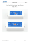
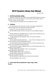
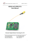
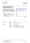
1
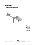
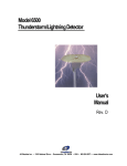
Temperature and Humidity data Transmitter
http://en.usr.cn
Temperature and humidity data Transmitter
Instruction Version: V1.0
Date:2014-4-15
USR-SENS-WSD-T
USR-SENS-WSD-2
USR-SENS-WSD-4
Jinan USR IOT Technology Limited
Page 1 / 18
[email protected]
Temperature and Humidity data Transmitter
http://en.usr.cn
Content
1. Introduction................................................................................................................................. 3
1.1 Overview........................................................................................................................... 3
1.2 Characteristics..................................................................................................................3
1.3 Features............................................................................................................................ 3
1.4 Interface definition............................................................................................................5
1.5 Default settings.................................................................................................................5
1.6 Tips before using..............................................................................................................5
2. Working mode.............................................................................................................................7
2.1 System Diagram...............................................................................................................7
2.2 Command Format............................................................................................................ 7
2.2.1 MODBUS command frame................................................................................. 7
2.2.2 MODBUS response frame...................................................................................8
2.2.3 MODBUS Frame Example.................................................................................. 9
2.2.4 MODBUS exceptional response...................................................................... 12
2.2.5 MODBUS exceptional responseframe example............................................ 13
2.3 ASCII commands........................................................................................................... 15
2.3.1 READ................................................................................................................... 15
2.3.2 AUTO....................................................................................................................15
2.3.3 STOP....................................................................................................................16
Appendix A:................................................................................................................................... 17
Language C implementation of CRC16 check algorithm....................................................... 17
3. Contract us................................................................................................................................18
Jinan USR IOT Technology Limited
Page 2 / 18
[email protected]
Temperature and Humidity data Transmitter
http://en.usr.cn
1. Introduction
1.1 Overview
USR-SENS-WSD temperature and humidity data acquisition module is of high
performance. With optional RS485 / RS232 / TTL different level output and MODBUS
industrial control bus protocol, it allows multiple modules connected to the bus network,
and build network with equipment in accordance with the MODBUS protocol , to monitor
Production site environment changes in time and steadily. So that users can accurately
grasp the changes of different applied field and act quickly to guarantee the stability of the
production site environment.
1.2 Characteristics
�
DATA/VCC/GND/RXD(RS85-A)/TXD(RS485-B)interface, simple and reliable, easy to
expand
� RS232/RS485/TTL signal transmitted methods
� Data transmission based on MODBUS Industrial control protocol, Reliable
performance, good compatibility, easy to network
� Support simple character instruction, single module easily used in simple applications
� Small size, easily installed
� Moisture-proof handling, suitable for damp environment as greenhouse
� Serial port configuration parameters:
Baud rate: 1200 / 4800 / 9600 / 19200 / 38400 / 57600
Data bits: 8
Parity: No / Odd / Even
Stop bit: 1 /2
Interrupt the power and restart, the configuration takes effect
Configuration commands, please refer to “2.2.3.7 Serial port parameter setting” in
“Chapter Two Working mode”
1.3 Features
�
�
�
Measuring Temperature Range: -40℃~80℃; Resolution: 0.1℃; Accuracy: ±0.2℃
Working temperature range: -40℃~80℃
Measuring humidity range: 0%~100% (RH) Relative Humidity; Resolution: 0.1%RH;
Accuracy:±2%RH at surrounding temperature below 25℃
Jinan USR IOT Technology Limited
Page 3 / 18
[email protected]
Temperature and Humidity data Transmitter
�
http://en.usr.cn
�
Working humidity range: 0%~100%(RH)Relative Humidity
Power input: 5V DC
Support data formats: serial MODBUS protocol, Simple ASCII character instruction:
“READ”, “AUTO”, “STOP”
The module ID can be configured, Range:1~247
�
Outline dimension:
�
�
Length: 65mm
Width: 46mm
Height: 28.3mm
Length: 20.3mm
Width: 9mm
Height: 11.3mm
Jinan USR IOT Technology Limited
Page 4 / 18
[email protected]
Temperature and Humidity data Transmitter
http://en.usr.cn
1.4 Interface definition
�
Interface arrangement:
�
�
�
�
DATA : reserved
VCC : VDD, 5V DC
GND : GND,signal ground
RXD/A: -T: TTL RXD signal line, -2: RS232 RXD signal line,
-4: RS485 A end signal line
TXD/B: -T: TTL RXD signal line, -2: RS232 RXD signal line,
-4: RS485 B end signal line
�
1.5 Default settings
1)
2)
Serial interface: Baud rate: 9600, Data bits: 8, Stop bits: 1, No parity bit
Module ID (“0x**” indicate hexadecimal numbers,the same below): 0x11
1.6 Tips before using
1. Certain foundation of the MODBUS protocol is necessary before you use this. Or refer
to “2.2 command format” in “Chapter Two Working mode” to design command you use
and upper computer program. Its data transmission is Serial MODBUS protocol,
accordingly, We provide technical support based on it. You can use network to serial port
module send module instruction and data via Serial MODUBS agreement. However, we
don;t support this knowledge and application solutions, please refer to relevant
documents.
Besides, it supports 3 ASCII commands to read the current environmental temperature
and humidity data (Note: Only one module is available on the line, more modules will lead
to disorder.) As for format and parameters of command, please refer to “2.3 Simple ASCII
Command” in “Chapter Two Working mode”
Jinan USR IOT Technology Limited
Page 5 / 18
[email protected]
Temperature and Humidity data Transmitter
http://en.usr.cn
2. Check code filed is necessary in sending and receiving commands. It adapts CRC16
check and respond to your commands when checked correct so as to ensure the
accuracy of the data transmission and stability of the system you build. The source code
of CRC checking is in “Appendix II”.
3. It receives commands of 8 byte, and variable length one is not available currently.
Although it may return commands of length more than 8 type, it result from that how much
data returned the module judge according
Jinan USR IOT Technology Limited
determines how much data should be output..
Page 6 / 18
[email protected]
Temperature and Humidity data Transmitter
http://en.usr.cn
2. Working mode
2.1 System Diagram
USR-SENS-WSD Temperature and humidity data acquisition module ( Module as
below) is temperature humidity data acquisition terminal in production site. It receives and
analysis MODBUS protocol frames send by computer, then return the data according to
commands.The module adopts five line interface (Data line reserved), and need computer
supply power. System diagram is as below:
USR-SENS-WSD
Request ADU
PC supply power
RS485/RS232/TTL
VCC/GND
PC
Respond
ADU
2.2 Command Format
The format of MODBUS protocol frames the module can support is as below:
2.2.1 MODBUS command frame
The Module performs initialization 2 seconds after power on, then receive MODBUS
protocol frames and execute according the computer commands.
Jinan USR IOT Technology Limited
Page 7 / 18
[email protected]
Temperature and Humidity data Transmitter
http://en.usr.cn
MODBUS command frameincludes: 1 Byte address field ( to instruct and respond the
module address of PC commands), 1Byte function code ( instruct module according to
assigned address to respond), 4Bytes Data ( instruct read/write begins and ends or data
will be written) and 2Bytes CRC.
The command frame address filed values “0x00~0xF7’. Broadcast acts when It
values 0, and All equipment support MODBUS protocol operates according to the
command, but does not return data.
function code support values:
“0x03”: read temperature and humidity data (temperature/humidity or temperature &
humidity)
“0x04”: read temperature and humidity data (temperature/humidity or temperature &
humidity)
“0x06”: set equipment ID and module serial parameters
Specially, when PC send broadcast command, the module support a customized
function code “0x6E”. The code will reset equipment ID to factory Default when users
ignore or not sure with module ID.
During reading temperature and humidity data, the first 2 Bytes means read begins
and ends. High byte is before low byte. (“0x00 0x00” means to read from the first data.
“0x00 0x01” means to read from the second data.) The last 2Byte means the number
of reading data. High byte is before low byte. (“0x00 0x01” means to read 1 data. “0x00
0x02” means to read 2 data.)
Error checking adapts CRC16. 2Bytes, High byte is before low byte, which is
recommended by MODBUS protocol.
2.2.2 MODBUS response frame
MDOBUS response frame includes: 1 Byte address filed (return module ID to
PC),1Byte function code/exception code ( return function code/exception code module
received). 2Bytes~5Bytes data (1Byte means the number of byte returned, 1Byte~4Bytes
means selectable data) and 2Bytes CRC check code ( used to error checking)
Response frame address filed =Command frame address filed. The module compare
address filed and CRC check code it get from PC command frame with own ID and
calculated one. If they are same, and CRC Check correct, it will read the data and send
respond frame. If not, no response.
Respond function code domain: function code support values
“0x03”: read temperature and humidity data (temperature/humidity or temperature &
humidity)
“0x04”: read temperature and humidity data (temperature/humidity or temperature &
humidity)
“0x06”: Set module ID and serial port parameters
“0x6E”: reset module ID
Jinan USR IOT Technology Limited
Page 8 / 18
[email protected]
Temperature and Humidity data Transmitter
http://en.usr.cn
Return Abnormal code: there’s two parts, 1 Byte each part. The first reveals where’s
the problem, the second directs how to slove it.
Data part 2Bytes~5Byte,During returned data, the first Bytes means numbers fo
bytes returned. Following 4 bytes means data returned, High byte is before low byte.
Humidity data is before temperature, High byte is before low byte. It is positive
temperature when its highest is 0, and negative temperature when it is 1. Returned data is
10 times higher than actual measurement data. As returned temperature data is 185 while
the actual is 18.5℃.
Error checking adapts CRC16. 2Bytes, High byte is before low byte, which is
recommended by MODBUS protocol.
2.2.3 MODBUS Frame Example
The below is MODBUS command frame format and respond frame format to read module
data.Command frame ID is not fixed and it is set by default in the example. All MODBUS
Frame ID should keep updated if users make re-configuration,Respond frame data is not
fixed, but the format fixed.
2.2.3.1 Read device ID
Respond frame:
0x11 0x03
ID
respond code
0x01
return byte number
0x11
device ID
0x34 0x84
CRC check code
2.2.3.2 Read Humidity data
Command frame:
0x11 0x04
ID
function code
0x00 0x00
begins and ends
0x00 0x01
read number of data
0x33 0x5A
CRC check code
Respond frame:
0x11 0x04
ID
respond code
0x02
return byte number
0x01 0xC3
return humidity data
0x39 0x32
CRC check code
Humidity data returned is 0x01C3, equal to decimalism 451. It means relativehumidity is
45.1% at moment.
Jinan USR IOT Technology Limited
Page 9 / 18
[email protected]
Temperature and Humidity data Transmitter
http://en.usr.cn
2.2.3.3 Read Temperature data
Command frame:
0x11
0x04
ID
function code
Respond frame:
0x11 0x04
ID
respond code
0x00 0x01
begins and ends
0x02
returned byte num
0x00 0x01
read number of data
0x62
0x9A
CRC check code
0x00 0xEE
return temperature data
0xF8
0xBF
CRC check code
Temperature data returned is 0x00EE, equal to decimalism 238. It means current
temperature is 23.8℃
2.2.3.4 Read Humidity & Temperature data
Command frame:
0x 11 0x04
ID
function code
Respond frame
0x11 0x04
ID
respond code
0x00 0x00
begins and ends
0x04
0x00 0x02
read number of data
0x01 0xC8
returned byte num
0x73 0x5B
CRC check code
0x00 0xED
0xAA 0x0A
Humidity data Temperature data
CRC check code
Humidity data returned is 0x01C8, equal to decimalism 456. It means relativehumidity is
45.6% .
Temperature data returned is 0x00ED, equal to decimalism 237. It means current
temperature is 23.7℃
2.2.3.5 Set module ID
Module ID is register variables with 0x0000 home address. It can be set via function code
0x06
Command frame:
0x11
0x06
ID
function code
Respond frame:
0x02
0x06
ID
respond function code
Jinan USR IOT Technology Limited
0x00 0x00
address
0x00 0x02
set ID
0x00 0x00
return address
0x00 0x02
return data
Page 10 / 18
0x0A 0x9B
CRC check code
0x08 0x38
CRC check code
[email protected]
Temperature and Humidity data Transmitter
http://en.usr.cn
2.2.3.6 Reset module ID
Command frame
0x00
0x6E
ID
function code
0x00 0x00
address
0x00 0x00
set ID
0xE9 0x D2
CRC check code
It is a pointed command. The module ID turns to 0x11 after receiving it. 0x6E is adapted
to avoid conflicts with other devices because it is of broadcast mode. And the module
reset ID as the four bytes behind function code are 0.
2.2.3.7 Sett serial parameters
Use function code “0x06” to set when the module internal address is 0x0001. During
address 0x0001, High byte is used to store baud rate parameters, low byte is used to set
check /stop bit. Setting format is as below:
Baud rate parameters:0
1
2
3
4
5
Check /stop bit parameters:
1200
4800
9600
19200
38400
57600
byte 7: byte 6
empty
high
Byte 5: byte 4
STOP : stop bit, to set bits of stop
00: 1 stop bit
10: 2 stop bits
Byte 3
empty
Byte 2 odd/even control enable: 0 disable/ 1 enable
Byte 1 odd/even select: 0even/ 1 odd
Byte 0
empty
low
Note: when the stop bit is set to 2, the check bit can only be set to 0. When check bit is
Odd/even, stop bit can only be set to 1. When using a simple ASCII command,
parameters of serial port Settings also must comply with the rules.
Command frame
0x11 0x06
ID
function code
0x00 0x01
address
Jinan USR IOT Technology Limited
0x02
baud rate
0x04
Check /stop bit
Page 11 / 18
0xDA
0x39
CRC check code
[email protected]
Temperature and Humidity data Transmitter
Respond frame
0x11 0x06
ID
respond function code
0x00
0x01
return address
0x02
0x04
return data
http://en.usr.cn
0xDA
0x39
CRC check code
The command set module baud rate to be 9600, 1 stop bit, even parity check.
2.2.4 MODBUS exceptional response
When the PC device sends a request to the module, PC hope a normal response.
The following four condition may occur in hub station inquiry:
1, If the module receives the request without communication error, and can properly
deal with inquiry, the module will return a normal response (a normal MODBUS frame)
2, If module does not receive the request due to communication error, and can't
return response, PC program will handle the timeout mode.
3, If module receives the request, but detect a communication error (Odd/even
check/LRC/CRC...) can't return response, PC program will handle the timeout mode.
4, If module receives the request without communication error, but can't deal with this
request (for example, if the request is to read a nonexistent output or register), the module
will return an exceptional response and reveal the essential of the user error.
Exceptional response packet has two domains different with the normal one:
Function code domain: In the normal response, the module responses function code
domain to answer function code of the initial request. All function codes’ most significant
bit (MSB) is 0 (their values are less than hex 80) while it is 1 in abnormal response,
which makes the function code in the exceptional response 0x80 higher than normal.
PC application can identify exceptional response and detect its data domain by
setting MSB of the function code.
Data domain: in normal response, the module can return data within or statistics (all
requirements requested) while module return abnormal data and defines the exceptional
state.
The example of user device request and server abnormal reply
Require
Respond
Domain
(Hex)
Domain
(Hex)
Function
01
Function
81
Start address Hi
04
Abnormal code
02
Start address Lo
A1
Output number Hi
00
Output number Lo
01
Jinan USR IOT Technology Limited
Page 12 / 18
[email protected]
Temperature and Humidity data Transmitter
http://en.usr.cn
In this example, the client requests addressing to the server equipment. Function
code (01) is used to read the output state operation. It will request output state of address
0 x04a1. It only read one output as output domain (0001) stated. If there is no output
address in the server device, the server will return exceptional response of exception code
(02) which means illegal data address.
The excel of MDOBUS exception code the module support is following:
MODBUS abnormal code
Code
Nama
Description
0x01
Illegal function
For modules, the received function code during
querying is un-allowed operation. Meanwhile, it indicate
that upper computer send requirements in error status,
example: as it is un-configured function, and need return
data
0x02
Illegal data address
For modules, the received data address during querying
is un-allowed address. Especially, the combination of
starting address and data number is invalid. For
modules, starting address 0x0001, request data number
is 0x0004 is invalid, will appear abnormal code0x02
0x03
Illegal data value
For modules, the value during querying is un-allowed.
This value indicate the remaining structure defaults in
combination request. Example: In MODBUS protocol,
address 0x00 used for broadcast, if try to set module ID
to be 0x00, will reply this abnormal code.
0x04
Module fault
This is not a standard abnormal code in MODBUS
protocol, but a customized abnormal code. When
module reply “0X0C”, need to judge the reason of the
code by commands that upper computer sent: when
upper computer command is to set module ID, module
need restart to set ID; when upper computer command
is read data, this code means not able to read data. At
this time, upper computer need to delay a few seconds
(should >2s) then send data. If still reply this code, it
means the sensor on module is broken, need repair.
frame example
2.2.5 MODBUS exceptional response
responseframe
2.2.5.1 Illegal function command
Jinan USR IOT Technology Limited
Page 13 / 18
[email protected]
Temperature and Humidity data Transmitter
Command frame:
0x 11
0x01
ID
function code
http://en.usr.cn
0x00
0x00
0x00
0x02
begins and ends read number of data
Respond frame:
0x11
0x81
ID
respond function code
0x01
exceptional code
0x73
0x5B
CRC check code
0x80 0x55
CRC check code
The command frame instruct module to read the first address 0 x0000 up the value of the
two coil (discrete) because the module is without discrete quantity, so the function code (0
x01) is not supported. If the response frame is exceptional, respond function code will add
0 x80 on function code received and response function code returned is 0 x81. function
code 0x01 is not supported, so exceptional code domain is 0x01 and so is check code
domain.
2.2.5.2 Illegal data address
Command frame:
0x 11 0x04
0x00
0x01
0x00
0x02
ID
function code begins and ends read number of data
0x73
0x5B
CRC check code
Respond frame:
0x11
0x84
ID
respond function code
0xC3 0x04
CRC check code
0x02
exceptional code
The command frame instruct module to read the first address0x0001 value of the two
registers. Because there’s only two registers within the module, respectively 0 x0000
(humidity) 0 x0001 (temperature data), so begins and ends and number of data of the
command frame requested is invalid, then module will return exceptional response frame
as the above. Respond function code will add 0 x80 on function code received and
response function code returned is 0 x84. Data requested by command frame is out of
range, so exceptional code domain is 0x02 and so is check code.
2.2.5.3 Illegal data values
Command frame:
0x 11
0x06
ID
function code
0x00 0x00
set address
Respond frame:
0x11
0x86
ID
respond function code
Jinan USR IOT Technology Limited
0x00
set ID
0x00
0x0C
exceptional code
Page 14 / 18
0x8B
0x5A
CRC check code
0x03 0xA4
CRC check code
[email protected]
Temperature and Humidity data Transmitter
http://en.usr.cn
The command frame instruct module to set ID to be 0x0, however, it is to broadcast in
MODBUS, so it is illegal then it will return a exceptional response frame. Respond function
code will add 0 x80 on function code received and response function code returned is 0
x86. Data requested by command frame is illegal, so exceptional code domain is 0x03
and so is check code.
2.2.5.4 Module fault
Command frame:
0x 11
0x04
ID
function code
0x00 0x00
begins and ends
Respond frame:
0x11
0x84
ID
respond function code
0x00 0x02
read number of data
0x0C
exceptional code
0x73
0x5B
CRC check code
0x42 0xC0
CRC check code
The command frame instruct module to return temperature and humidity data. If module
Sensor fault occurs, right data cann’t be received. Then it will return a exceptional
response frame. Respond function code will add 0 x80 on function code received and
response function code returned is 0 x84. The module is at abnormal stage, so
exceptional code domain is 0x0C and so is check code.
2.3 ASCII commands
ASCII commands include 4 ASCIIcharacters. Data transmission are ASCII.
2.3.1 READ
It is to read environment temperature and humidity data once.
Send instruction format: READ
Return data format: 29.8,56.5%
2.3.2 AUTO
It is to instruct to return current environment temperature and humidity data every 2
seconds.
Send instruction format:AUTO
Return data format: 29.8,56.5%
Jinan USR IOT Technology Limited
Page 15 / 18
[email protected]
Temperature and Humidity data Transmitter
http://en.usr.cn
2.3.3 STOP
It is to stop returning environment temperature and humidity data.
Send instruction format: STOP
Return data format: No
Jinan USR IOT Technology Limited
Page 16 / 18
[email protected]
Temperature and Humidity data Transmitter
http://en.usr.cn
Appendix A:
Language C implementation of CRC16 check algorithm
const unsigned int ccitt_table[256] =
{0x0000, 0xC0C1, 0xC181, 0x0140, 0xC301, 0x03C0, 0x0280,0xC241, 0xC601,
0x06C0, 0x0780, 0xC741, 0x0500, 0xC5C1, 0xC481,0x0440, 0xCC01, 0x0CC0,
0x0D80, 0xCD41, 0x0F00, 0xCFC1, 0xCE81,0x0E40, 0x0A00, 0xCAC1,
0xCB81, 0x0B40, 0xC901, 0x09C0, 0x0880,0xC841, 0xD801, 0x18C0, 0x1980,
0xD941, 0x1B00, 0xDBC1, 0xDA81,0x1A40, 0x1E00, 0xDEC1, 0xDF81, 0x1F40,
0xDD01, 0x1DC0, 0x1C80,0xDC41, 0x1400, 0xD4C1,0xD581, 0x1540, 0xD701,
0x17C0, 0x1680,0xD641, 0xD201, 0x12C0, 0x1380, 0xD341, 0x1100, 0xD1C1,
0xD081,0x1040, 0xF001, 0x30C0, 0x3180, 0xF141, 0x3300, 0xF3C1,
0xF281,0x3240, 0x3600, 0xF6C1, 0xF781, 0x3740, 0xF501, 0x35C0,
0x3480,0xF441, 0x3C00, 0xFCC1, 0xFD81, 0x3D40, 0xFF01, 0x3FC0,
0x3E80,0xFE41, 0xFA01, 0x3AC0, 0x3B80, 0xFB41, 0x3900, 0xF9C1,
0xF881,0x3840, 0x2800, 0xE8C1, 0xE981, 0x2940, 0xEB01, 0x2BC0,
0x2A80,0xEA41, 0xEE01, 0x2EC0, 0x2F80, 0xEF41, 0x2D00, 0xEDC1,
0xEC81,0x2C40, 0xE401, 0x24C0, 0x2580, 0xE541, 0x2700, 0xE7C1,
0xE681,0x2640, 0x2200, 0xE2C1, 0xE381, 0x2340, 0xE101, 0x21C0,
0x2080,0xE041, 0xA001, 0x60C0, 0x6180, 0xA141, 0x6300, 0xA3C1,
0xA281,0x6240, 0x6600, 0xA6C1, 0xA781, 0x6740, 0xA501, 0x65C0,
0x6480,0xA441, 0x6C00, 0xACC1, 0xAD81, 0x6D40, 0xAF01, 0x6FC0,
0x6E80,0xAE41, 0xAA01, 0x6AC0, 0x6B80, 0xAB41, 0x6900, 0xA9C1,
0xA881,0x6840, 0x7800, 0xB8C1, 0xB981, 0x7940, 0xBB01, 0x7BC0,
0x7A80,0xBA41, 0xBE01, 0x7EC0, 0x7F80, 0xBF41, 0x7D00, 0xBDC1,
0xBC81,0x7C40, 0xB401, 0x74C0, 0x7580, 0xB541, 0x7700, 0xB7C1,
0xB681,0x7640, 0x7200, 0xB2C1, 0xB381, 0x7340, 0xB101, 0x71C0,
0x7080,0xB041, 0x5000, 0x90C1, 0x9181, 0x5140, 0x9301, 0x53C0,
0x5280,0x9241, 0x9601, 0x56C0, 0x5780, 0x9741, 0x5500, 0x95C1,
0x9481,0x5440, 0x9C01, 0x5CC0, 0x5D80, 0x9D41, 0x5F00, 0x9FC1,
0x9E81,0x5E40, 0x5A00, 0x9AC1, 0x9B81, 0x5B40, 0x9901, 0x59C0,
0x5880,0x9841, 0x8801, 0x48C0, 0x4980, 0x8941, 0x4B00, 0x8BC1,
0x8A81,0x4A40, 0x4E00, 0x8EC1, 0x8F81, 0x4F40, 0x8D01, 0x4DC0,
0x4C80,0x8C41, 0x4400, 0x84C1, 0x8581, 0x4540, 0x8701, 0x47C0,
0x4680,0x8641, 0x8201, 0x42C0, 0x4380, 0x8341, 0x4100, 0x81C1,
0x8081,0x4040, };
unsigned int cal_crc16(unsigned char *ptr, unsigned char len)
{
unsigned int crc = 0xffff;
Jinan USR IOT Technology Limited
Page 17 / 18
[email protected]
Temperature and Humidity data Transmitter
http://en.usr.cn
while (len-- > 0)
crc = ccitt_table[(crc ^ *ptr++) & 0xff] ^ (crc >> 8);
return crc;
}
3. Contract us
Jinan USR IOT Technology Limited
Address: 1-728, Huizhan Guoji Cheng, Gaoxin Qu, Jinan, Shandong, China
Tel: 86-531-55507297
86-531-88826739-803
Web: http://en.usr.cn
Skype: lisausr
Email: [email protected]
[email protected]
Jinan USR IOT Technology Limited
Page 18 / 18
[email protected]