1
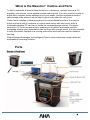
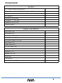
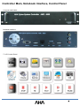
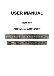
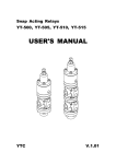
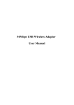
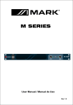
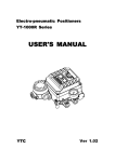
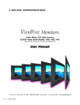
Maestro Podium
User manual
Contents
Product Overview ..................................................................................... 3
Parts Overview .......................................................................................... 3
Components ............................................................................................. 4
Specifications ............................................................................................ 5
System Block Diagram .............................................................................. 7
Controller main, Notebook interface, Control panel ................................ 8
Controller back panel ................................................................................. 9
Controller connection ............................................................................... 10
Controller connection layout ................................................................... 11
Electric Light control, Relay default positions ......................................... 12
Motorized screen and Operating relays .................................................... 13
Operation instructions ............................................................................. 14
IR Learning …............................................................................................. 14
Projector Protocol Input ........................................................................... 16
Trouble shooting ........................................................................................ 17
2
What is the Maestro? Outline and Parts
To hold a computer & internet based lecture in a classroom, devices such as a PC,
amplifier, microphone, and a speaker system are required. You also need to be able to
adjust fairly complex device settings to suit your needs, and the equipment needs a
safe storage place where it can be kept in good order when it’s not in use.
These needs resulted in developing the all-in-one multimedia podium. It is easy to
move and has a built-in controller to control each device with one touch, while a
multimedia desktop PC can be put inside the compact design cabinet. The highly
sensitive LCD Touch screen monitor enables you to deliver impressive lectures,
navigating through your presentation can be done with a single touch. It is also possible
to save the lecture contents in a moving picture file which can be used for distance
learning.
With all these advantages, the Intelligent Power Lectern becomes a state-of-the-art
multimedia E-Learning Solution.
Parts
3
Components
Lectern
2ch 700Mhz Wireless Microphone
1
5 Input (3ch mic. 2ch AUX) 1 Output Stereo AMP
1
Notebook interface module
1
LCD Monitor
1
Gooseneck Microphone
1
Controller - 7” LCD Type
1
Speaker (4 Ohm 20 W)
2
Combo (option)
1
Cable and Others
RGB Cable 1.5m
3
USB Cable 1.5m
4
Mini-stereo Cable 1.5m
4
RCA AV Cable (3:3) 1.5m
1
RCA Audio Cable ( 2:2) 1.5m
1
LAN Cable 1.5m
2
Power Code 1.5m
5
RS –232 Cable 1.5m
1
Power Code 1.5m
5
Adapter 5V 1A
1
Adapter 19V 3.4A
2
Tablet Pen
1
User Manual
1
Driver & Software CD
1
4
Specifications
Controller Specifications
VGA
Sound
Video
Control
Other
AMC-6000
VGA Input
VGA x 3
VGA Output
VGA x 2
Signal Type
VGA, SVGA, XGA, QXGA
Max. Resolution
2048 x 1536
Pixel Frequency
440 Mhz
Audio Input
Audio x 5
Audio Output
Audio x 1
Frequency Response
20 Hz ~ 20 KHz + 1 / -3 dB
Video Input
Video x 2
Video Output
Video x 2
Bandwidth
100 MHz
Return Loss
-30 dB; 5 MHz
Projector Power Control Port
x1
Screen Control Port
x1
Serial RS-232 Port
x1
Power
220 ± 10% 50/60 Hz 5A
Weight
1 kg
Size
420 x 84 x 250 mm
5
Amplifier Specification
AMX – 3020W
Maximum power ( 1KHz : THD < 1%) 4ohm
200W+200W
Total Harmonic distortion
<0.05%
Intermodulation distortion
<0.08%
Cross talk (at 1KHz)
< -80dB
Microphone Input Sensitivity 1-6CH
0.8mV at 600 Ohm
Singnal to Noise ratio Mic 1-6
Better than 60dB
Auxiliary Input Sensitivity 1-2
100mV at 47k Ohm 700mV
Tone control range
Bass +or -10dB at 100Hz Treble +or -10dB at
10kHz
Main power supply
220 ~ 240V AC at 50~60Hz
Power consumption
280W at rated power
Dimensions (WHD)
420 X 84 X 350 mm
Weight
15.7kg
6
System Block Diagram
7
Controller Main, Notebook Interface, Control Panel
Controller AMC-6000
Notebook Interface
7” LCD Control Panel
8
Controller Back Panel
a
A/V OUT: Video Sound Output port. Connect to Projector & Amplifier.
b
A/V INPUT : Connect DVD, VCR , Visualizer, etc.
c
Mic. Input: Connect MIC 1, MIC 2. (MIC1 supports 12V phantom power)
d
TOUCH : Connect LCD touch screen.
e
POWER CONTROL: To control external devices power & screen elevation.
f
AC Out: Security function port. If USB KEY is pulled out, all connected devices go off.
g
AC In : Supplies power to control AC Out and 220V Devices (screen, elevation).
h
PC Sound: PC’s speaker port is connected to IN port, mic port is connected to OUT.
i
Notebook Sound : Notebook speaker port is connected to IN, MIC port is connected to OUT.
j
USB : USB from monitor is to Tablet, AUX port is used to expand at PC. (see configuration)
Others are selector ports of PC and Notebook. Each one connects to PC and Notebook.
k
LAN : Selector port of Notebook and PC. Main LAN cable is connected to LAN IN, others are
connected to PC and Notebook’s internet port.
l
IR Control : for IR signal output.
m
PROJECTOR : RS-232 port to control projector. (connected to projector)
n
CONTROL : Connected to PC by RS -232
o
PC POWER : PC power control port (Connected to PC’s power port)
p
RGB distributor : Distribute RGB signal and output images to monitor and projector (selector
function included)
q
KEY Control : Port connected to keys
r
Power: 19V 3.16A
9
Controller Connection
AMC-6000 rear
10
Controller Connection Layout
11
Electric Light Control, Relay Default Positions
12
Motorized screen and elevation control:
Operating relays with 220V power or without power
Motorized screen and elevation control (220V)
1) AMC - control the screen by 600 touch controller
2) Push the Down button to lower the screen
3) Pusg the Stop button to stop lowering or raising the screen
4) Push the Up button to raise the screen
*Note, The controller is set up to control the projection screen and projector elevator by the
relays for this function, switching the 220V that is fed to the controller on the right top socket.
If you intend to control these functions by simply opening and closing a circuit that is not
powered by the relays itself, do not attach the 220V in the socket at the back of the controller.
Instead wire as below, otherwise systems attached to these Phoenix plugs may get damaged.
Internal layout for screen and elevation (220V)
The screen and elevation each have 2 relays.
13
Operation Instruction
• If you press START button, screen and elevation will come down and the projector will be turned on.
This function can be expanded to other external devices like fluorescent light, electric fan, air
conditioner, etc.
• If the END button is pressed, screen and elevation will go up, and the projector will be automatically
turned off.
Use of a computer
Desktop PC
• In the LCD Menu, press the PC button. * at initial power input, PC mode will automatically be set.
Notebook
• In the LCD Menu, press the NOTE button.
• Connect the Notebook power adaptor, RGB Cable,USB, SOUND IN / OUT, LAN cable to the notebook
connection socket. Internet, sound, and pen function will automatically be set. * In order to use a tablet
on the notebook, you need to install the tablet driver on the notebook as well.
• To return to the main computer, press the PC button.
IR Learning
• The Controller can save remote control’s input signal and do the control.
• How to program
• At Television MENU on the LCD, press IR Learn button, the controller panel LED will be on.
(Program Ready Status)
• Press desired key on the LCD.
• Press remote control signal for that key on the controller main set.
• Upon the desired button input completed, LED will flicker.
• In case of wrong input, LEC will flicker fast. Then, input again.
How to connect
• On the back of controller, “IR Control Out” port is consisted of 4CH. Connect IR cable to the desired
channel, and attach to the IR light receiving part of the equipment to be controlled.
When there is no response to pressing the button, there is an input error, or the light emitting position of
the cable is not correctly matched with the light receiving part of the device. In this case, follow the
procedure again.
14
In order to input IR Learning into the Controller, the PC RS-233 port whould be connected with
the Controller’s control RS-232 port.
Sequence
1. First copy vb6ko.dll file in the System32 folder, and install Vbruntimes.
(If it is not installed, you will get an error.)
2. Next, execute Protocol Input and set the COM Port. (check your PC’s port number.)
3. Press the Open button, Program Input LED is lit.
4. On the Window screen, press the ON/OFF button.
5. Press the Remote control’s ON/OFF button while you point it at the Controller’s IR Receiver.
6. If the input was successful, the LED blinks 3 times. If it wasn’t, the LED blinks rapidly.
7. Input other buttons following the above procedure.
8. When all input is completed, use the IR Cable to connect to the Controller’s IR Port, and place it
near to the IR Receiver you want to control.
15
Projector Protocol Input
In order to input IR Learning into the Controller, the PC RS-233 port whould be connected with
the Controller’s control RS-232 port.
Sequence
1. First copy vb6ko.dll to the System32 folder, and install Vbruntimes.
(If it is not installed, you will get an error.)
2. Next, execute Protocol Input and set COM PORT. (check your PC’s port number.)
3. If you press the OPEN button, COM PORT opens. If the PORT setting is wrong, an error message is
displayed.
In this case, open the device manager and recheck the port before resetting.
4. Select your Projector.
5. If you press the next protocol button, a matching LED flashes. While the protocol is being input, do
not press any other button, and wait until the LED stops flashing. If an other button is accidentally
pressed, the next button input can not be made. In this case, connect the power again and proceed with
the input.
6. After all input is completed, press CLOSE button to close COM PORT.
16
Trouble Shooting
Problem
Check Point
No Power
• Is the Power cord connected?
• Is the Podium Power switch ON?
• Is the Monitor power connected?
No Image
• Is the PC select switch on the upper control panel
properly selected?
• Is the Input device cable connected?
• Is the Tablet monitor’s VGA input connected?
• Is the Output device cable connected?
Strange Color
• Check if the pins of the computer cable are
broken or bent
• Adjust the brightness and contrast of the Tablet
Monitor
Microphone Doesn’t Work
• Check the transmitter battery
No Sound
• Check volume levels
• Is the Computer input/output connected?
• Check Notebook settings for Voice input/output
17
3011 Hakwoon-ri, Yangchon-myeon, Gimpo-si, Gyeonggi-do, South Korea
TEL 031-997-0909
Visit us online at :
www.ahatouch.com
Ver 1.0