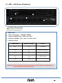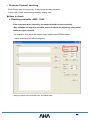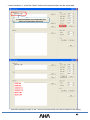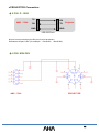
1
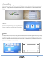
ELF Podium User manual MODEL : ELF-192D Contents I. What is the ELF? Outline, Components and Access --------------------------------- 3 II. AMC 7000 Connecting a Computer and Display Device to your Elf Podium - Connecting the operating computer ------------------------------- 6 - Tablet display driver installation -------------------------------- 7 - Projector / Display connection ------------------------------- 8 III. Navigating the Elf’s touch control pad - Password entry -------------------------------- 10 - Home ------------------------------- 10 - Setup -------------------------------- 10 - Multi -------------------------------- 11 - Volume -------------------------------- 11 - Control ------------------------------- 12 IV. AMC 7000 connection diagrams and user guide - Diagram of Elf controller ports ------------------------------- 14 - VGA Connection ------------------------------- 15 - RS-232 Connection ------------------------------- 16 - LAN Selector ------------------------------- 17 - USB Selector ------------------------------ 18 - IR Connection ------------------------------- 19 - SCREEN / ELEVATION Connection ------------------------------- 20 - AUX Switch Connection ------------------------------- 21 - Video Connection ------------------------------- 22 - RMS Connection ------------------------------- 23 - AMP Control Connection ------------------------------- 24 - IR Learning ------------------------------- 25 V. AMX3030D connection and user guide - Input Connection ------------------------------- 27 - Microphone Connection ------------------------------- 28 - PC Sound Connection ------------------------------- 29 - Audio Selector ------------------------------- 30 - Speaker Connection ------------------------------- 31 - How to use MIC and Amplifier ------------------------------- 32 VI. APD – 600 Power Distributor ------------------------------- 33 VII. Protocol Input and Checking - Projector Protocol Input ------------------------------- 35 - Projector Protocol Checking ------------------------------- 36 - PROJECTOR Connection -------------------------------- 38 VIII. RFID Card Registration - How to input the cards ------------------------------- 40 - Executing the Program ------------------------------- 41 - Register ID and Save -------------------------------- 43 IX. Register RMS and user guide - Wiznet Setting -------------------------------- 45 X. Firmware Update - Update procedure -------------------------------- 48 XI. Digital Podium Specification ------------------------------- 51 XII. Self-service , Warranty ------------------------------- 53 2 Ⅰ. What is the ELF? Outline, Components and Access What is the Elf? The Elf system allows the user to write on a tablet monitor built into the podium. The core technology system allows the user to write directly on a multimedia based teaching plan and save the images or video along with the voice, for the easy production of multimedia learning contents. The Elf has a built-in sound system (amplifier, wired/wireless microphone, etc..) for elearning and can be interfaced with all multimedia devices and facilities that the user might employ as teaching or communication tools. The embedded integrated controller allows for the control of devices with a single key and supports plug & play function. An additional 19” LCD monitor allows the presenter to manage contents, notes, and materials separate from what is being presented. Components 3 How to access the Elf The Elf system comes with its own power distributor, audio amplifier, wireless microphone receiver, and controller. You will need to access these devices in order to setup the Elf and connect it to other tools that the Elf will utilize (DVD player, projector, LCD display, etc). The Elf‟s devices can be accessed through its main door, or by removing its front plastic cover. ♦ Main access door. The main access door is located below the monitors and keyboard. This door is also supplied with a lock and key to prevent tampering when the system is not in use. Opening this door will give you access to the Elf‟s hardware control and setting switches. This door can be locked, unlocked, or removed entirely. The door‟s lock can be found to the left on the side of the Elf. To remove this door, locate its two spring loaded hinges and pull them out of their holes. To reach the Elf‟s hardware connections, remove the white plastic front access panel. Main access door Main access door lock and key Door hinge and panel release ♦ Front access panel. The front access panel must be unlocked by a switch inside of the Elf. This switch can be found at the top-right of the inside compartment, just below the keyboard tray, and near the top hinge of the main access door. Pulling the ring and switch will release the locking mechanism holding the cover in place. A rope has been attached to the cover to prevent it from falling after pulling the release switch. Removing this panel will allow you to access the connection ports for the Elf‟s devices. Front access panel Panel release switch Panel locking mechanism Front panel locking bar 4 Ⅱ. Connecting a Computer and Display Device to your Elf Podium 5 Connecting the operating computer 1. - Select the computer you would like to use for operating the podium and place that computer inside of the podium by opening the main access door. Remember that it will need to be stored on its side. This will not affect its operation. Also prepare the computer‟s mouse and keyboard. Place the keyboard on the pull out tray, and the mouse on the mouse pad. 2. - Run the Elf‟s power cable, originating for the power adapter, through one of the holes found on the bottom left or right. Power Cable 3. - Moving to the back of the Elf, you should find a group of cables originating from the Elf‟s Multimedia controller and Amplifier (USB, audio, VGA, LAN). You will also find a cable to power the computer coming from the Power Adapter, and a DVI cable originating from the Elf‟s sub display. VGA Cable DVI Cable 4. – You can start by connecting your mouse and keyboard to the computer. Next, in the group of cables originating from the Multimedia Controller, find the blue VGA cable. Connect it to the video out port on your computer. This cable will connect your computer to the Elf‟s tablet monitor. Also connect the DVI cable to your computer. This cable is connected to the Elf‟s sub display, and connecting it to your computer will enable you to operate with dual displays. 5. You may now connect both the “audio in” and “audio out” cables. The audio cables will connect from the computer to the “digital amplifier, AMX-3030D.” The 1/8 inch “PC audio in and out” jacks can be found on the 6 back of the amplifier. Connect these two cables to your computer‟s audio jacks. The computer‟s audio output will be coloured green and the input will be coloured pink. The cable originating from the AUDIO OUT port should be connected to your computer‟s green audio out port, and the cable originating from the AUDIO IN port should be connected to your computer‟s pink audio in port. If you plan on recording your lesson‟s audio at any time, it is necessary that the computer‟s “audio in” port is connected properly. 6. - Connect the remaining USB cables to your computer as well. These are for data sharing, laptop interface connection, and touch sensitivity for the Elf‟s tablet monitor. 7. - If connecting the Elf to the internet or a network, you will need to connect it using an external LAN cable. The port you should connect the LAN cable to is titled LAN IN, and can be found on the back of the Controller. You can route this LAN cable into the podium by using the same hole you routed the power cable through. In the group of cables that you had originating from the controller, attach the LAN cable to your computer. Tablet display driver installation 1. - In order to register touch input through the Maestro‟s tablet display, you might need to upload a driver. This driver can be found on the cd that came with the Maestro. If your computer is operating with Windows 7 and has Microsoft‟s current touch drivers and software installed, the additional driver may not be necessary. 2. – To install, place the disc in your computer‟s cd-rom drive and click „next‟ when the first window appears. 3. - The installation will begin and you will see the progress bar showing the state of installation. When the installation is finished you will be asked to restart your computer. In order to complete installation correctly you must restart your computer. It is suggested you restart immediately after you install the driver. 4. - After restarting your computer you will be able to use the electronic pen to input touch through the tablet monitor. 7 Projector / Display connection You will want to share and present material on the Elf to an audience in a larger format. To do so, you will need to connect the Elf‟s video output to a projector or other display device. These can be connected in two ways. PROJECTOR RGB (VGA) – If the video hardware you‟re connecting to has a VGA input, you can connect to the PROJECTOR RGB output on the AMC-7000. Also be aware that the terms RGB and VGA are often used interchangeably. VIDEO OUT (RCA connection) – If the video hardware you‟re connecting to has a yellow RCA input, or “composite video” input as it is commonly referred, you can connect it to this output as well. PROJECTOR 1 / PROJECTOR 2 Control (RS232C connection) – If the video hardware you‟re connecting to has an RS232C input, you can connect to this output. The RS232C cable will have 5-pins on its top and 4 on its bottom. This connection is not used for transferring video, but instead for device control. When connected, you can program the Elf‟s controller to command power and other menu functions of the video display device. ALTERNATIVE CONNECTIONS – There are a number of video connection types available for a number of devices. HDMI, DVI, and Component video inputs are the most popular amongst the several available. The Elf‟s controller provides connection to video devices through VGA and RCA. While many devices will connect directly to these ports, some will not have either VGA or RCA. In this case, it will be necessary for you to purchase a conversion cable. Cables for converting VGA and RCA to other formats are common and should be available at any electronics, or audio/video store. 8 III. Navigating the Elf’s touch control pad 9 ♦ Password Entry After turning on the Elf, the 7” touch control will display a screen asking you to input your password. Enter your 4-digit password and press the Enter button. This will take you to the controller‟s home display. ♦ Home From the “Home” screen you can enter Multi, Voice, Control, or the Setup menu for the LCD controller. ♦ Setup The Setup menu allows you to adjust basic operational settings for the controller. The first three buttons change the brightness settings of the control pad. The next two buttons control volume and IR input settings. The final button is for calibrating the touch sensitivity of the control pad. To calibrate touch, you must press on the cross points where they appear on the control pad. 10 ♦ Multi Selecting Multi will initiate the Elf system by automatically choosing your computer as the source to display. Your computer will be displayed on the Elf‟s monitors, and if connected to, your external display device (projector or television) will be turned on. Sources appear along the top of the screen, and the source being used at the time will be shaded. Sources - The first source is Computer, this is the Elf‟s main computer. The second source is Laptop and this will select whatever device you have connected to the Elf‟s Laptop Interface. The next button is Visual and it will allow you to choose to display other devices such as dvd or blue ray players. Selecting a different source will display both the visual and audio outputs from the selection. When computer or Laptop are selected, the volume settings will remain below to control the Gooseneck Microphone, Wireless Microphone and main volume levels. Visual – Selecting Visual allows you to choose from other AV equipment you have connected with the Elf. You are also able to control basic functions for the equipment. After you have taught the Elf the proper IR signals, you can turn the equipment on or off and operate basic controls for playing media. ♦ Volume The Volume menu contains the same volume options as when having Computer or Laptop selected. In this menu is possible to adjust the volume levels of the Gooseneck Microphone, Wireless Microphone, and the source output. Don‟t forget that the master control is located on the Elf‟s amplifier. This volume control will determine the final output level. 11 ♦ Control Selecting Control from the Home menu will provide you with the ability to control equipment external to the Elf podium. The controller can be set-up to operate things such as external microphones, displays, projectors, lights, or even room temperature controls. Table Mic – Controls microphones external to the Elf. Use this to control volume and tone for microphones other than the Elf‟s standard gooseneck and wireless microphones. LCD/Projector – Selecting this button will bring up Table Microphone power and source options for your video display device. It‟s possible to turn your display device on or off and choose which input it will display. Light – If connected to your Elf podium, you can control your lecture hall or presentation room‟s lighting in this menu. Here it is possible to turn the LCD lights either on or off. Motor – Selecting Motor will give you options for controlling your projector and projector screen. If you‟ve connected the control cables to the Elf, you will be able to raise or lower the screen, or change the elevation of the projector. Motor Tone – Tone settings for the Gooseneck, Wireless, and source audio outputs are found here. You may adjust each until you find a level that sounds appropriate to you. Tone 12 IV. AMC 7000 connection diagrams and user guide 13 Diagram of Elf controller ports Controller (AMC-7000) ⓐ ⓥ ⓟ ⓘ ⓧ ⓚ ⓣ ⓛ ⓐ IR OUT : IR output. ⓑ PROJECTOR 1 : Connect projector with RS-232 ⓒ PROJECTOR 2 : Connect projector with RS-232 ⓓ TOUCH : Connect 7” LCD Controller . ⓔ PROJECTOR : Projector VGA OUT. ⓕ MONITOR : Monitor VGA OUT. ⓖ PC : Computer VGA IN. ⓗ LAPTOP : Laptop VGA IN. ⓘ RMS : Input the Remote control LAN ⓙ DC 9V ⓑ ⓤ ⓒ ⓓ ⓨ ⓕ ⓖ ⓔ ⓗ ⓩ ⓙ : Main power input. ⓚ Video OUTPUT : Video and Audio output. ⓛ Video INPUT : Video and Audio input. ( A/V Selector). ⓟ AUX SW : Power and Switch control ⓠ Slide Switch : Firmware input switch. (left : Operating Mode, right : Input mode) ⓣ USB Port : Tablet Monitor ; PC PC USB ; NOTE Notebook Interface ⓤ LAN : LAN IN Main Input ; PC PC LAN Input : NOTE Notebook Interface ⓥ SCREEN / ELE : Connect Screen and elevation * Unavailable DC ⓧ AMP Control ⓨ PC / RFID : PC program input and Connect RFID Reader . ⓩ Switch : Firmware Update 14 VGA Connection Selecting an operating computer ♦ To use a desktop computer: 1) Choose „Desktop‟ by pushing the button on the 7inch touch control pad. * Default setting will have „Desktop‟ mode selected. ♦ To use a Laptop. 1) Choose „Laptop‟ by pushing the button on the 7inch touch control pad. 2) Connect the Laptop power adapter, RGB Cable, USB, and sound input. Connect the LAN Cable with the Laptop socket on the podium‟s upper cover . * To use touch function, software must be installed on the laptop 3) Choose „Desktop‟ to go back to the main computer. 15 RS-232 Connection RS-232 PIN Map PC / RFID TOUCH PIN Signal 2 TX 3 RX 5 GND PIN Signal 2 TX 3 RX 5 GND 7 5V PROJECTOR 1 PROJECTOR 2 PIN Signal PIN Signal 2 TX 2 TX 3 RX 3 RX 5 GND 5 GND 16 LAN Selector LAN Selection ♦ Using the computer‟s LAN. 1) Choose „Desktop‟ by pushing the button on the 7inch touch control pad. * Default setting will have „Desktop‟ mode selected. ♦ Using a Laptop‟s LAN. 1) Choose „Laptop‟ by pushing the button on the 7inch touch control pad. 2) Choose „Desktop‟ to go back to the main computer. 17 USB Selector USB Selection ♦ Using the computer‟s USB. 1) Choose „Desktop‟ by pushing the button on the 7inch touch control pad. * Default setting will have „Desktop‟ mode selected. ♦ Using a laptop‟s LAN. 1) Choose „Laptop‟ by pushing the button on the 7inch touch control pad. 2) Choose „Desktop‟ to go back to the main computer. 18 IR Connection IR Connection ♦ Connect a Device. (DVD players, cable boxes, or any devices with IR controllers) 1) Connect the IR cable supplied with the device to its IR port. 2) Connect the other end of that cable to “IR1” on the back of the multi controller (AMC-7000). Using another cable, connect one end to IR2 and the other to your display device‟s IR input.. 3) If the cable is too short, you may connect another cable by using a gender adaptor. ♦ Working test. 1) Firstly if you want to check if LED works correctly, you can check the blinking of LED after pushing the related button on the 7inch LCD pad by mobile phone camera or normal camera. 2) Regarding how to input IR, please refer to following IR Learning pages. Warning 1 : So that LED can communicate with device’s IR receipt part well, it should be close to receipt part. !Warning 2 : When extending an IR cable, signal breakdown may occur. This is more likely to happen if more than one cable is used. 19 SCREEN / ELEVATION Connection Controlling a Screen ♦ Automatic screen or elevation (Up / Down) control 1) User can move the screen up and down by using the AMC – 7000 touch controller. 2) When pushing the „STOP‟ button, the screen will be stopped. 3) When pushing the „DOWN‟ arrow button, the screen will move DOWN. 4) When pushing the „UP‟ arrow the screen will move UP. ! Warning1 : There is a 220V plug outside of the controller. When connecting the controller‟s 220V to POWER IN to this plug, 220V will be supplied to screen‟s elevation motor. If there is power also supplied outside of this, the controller will be overloaded. ! Warning2 : Please check if the screen‟s elevation motor is AC or DC. The controller will send an AC current and damage any DC motors that are connected. 20 AUX Switch Connection AUX circuits AUX 1 Relay 1 C AUX 1 2 AUX 2 Relay 1 C 2 AUX 2 ☞ When first turned on, the default connections are 1 and C. 21 Video Connection Video source selection ♦ User can select alternate video sources by using input 1 or 2 1) External video sources can be connected through the laptop interface and main controller . There is also an audio terminal in the amplifier where the audio from these video sources can be connected. 2) When pushing the A/V Selection button, the user can select input 1 or 2. 3) The video source that is chosen to be output will also have its audio output from the amplifier, if available. 22 RMS Connection System flow ☞ Main function ◆ By using a network module, all equipment that can be controlled in the podium can also be controlled through a server. - Projector ON/OFF function. - Screen UP/DOWN control. - Control of other video equipment and sound equipment. - Status monitoring. - Checking the connection of the network. 23 AMP Control Connection Amplifier control ♦ Amplifier connection. 1) The Controller and Amplifier are connected using a UTP cable. 2) Using 1 : 1 UTP line (can use previous LAN cable) * „PC Sound‟ is installed as the default audio source. ! Warning : The type of communication between controller and amplifier is 12C communication. If more than 1m of line is used between the controller and amplifier, communication may become distorted or disconnected. ♦ Reset function and tone adjustment. 1) Configuration It is possible to return to initial volume settings by using the reset option. 2) In Tone menu, PC or MIC levels can be regulated. 24 ☞ IR Learning If using the Elf to control external devices, the Elf‟s controller (AMC-7000) must be programmed to recognize them. It can control equipment by storing that equipment‟s remote control signals. PROJECTOR 1 and PROJECTOR 2 ports must be connected to devices using an RS-232 connection. Devices without an RS-232 connection can be controlled via REMOTE TRANSMITTER ports IR-1 and IR-2. ♦ DVD , VCR input 1) Select the device you want to program. Push the „Pause‟ button of the „Combo Menu‟ 5 times. 2) The main controller‟s (AMC-7000) red „Program LED‟ light will then be turned on. 3) Push the button (on the 7inch LCD control pad) for the attribute of the DVD, VCR or other device you would like to program to control through the Elf. 4) Using the device‟s remote control, push the corresponding button for the attribute you selected to program, and point the remote control toward the „IR receiver‟ of the main controller. 5) If input was finished correctly, the main controller‟s „Program LED‟ will still be flickering. If the LED is flickering very quickly, an error occurred while inputting the signal. You must try to complete the process once more. 6) When all inputs are finished, push the „Mute Off‟ button 5 more times. The main controller‟s „Program LED‟ will then be turned off. 7) After inputting the signals and turning off Program mode, check that you completed the process correctly by trying to operate your device with the Elf‟s control pad. 25 V. AMX3030D connection and user guide 26 Input Connection Digital Amplifier (AMX-3030D) ⓐ ⓔ ⓒ ⓕ ⓓ ⓖ ⓗ ⓛ ⓑ ⓙ ⓚ ⓐ Power input (220V 50/60 Hz) ⓑ GND ⓒ Speaker terminal ⓓ AMP Control : Connect to AMC 7000. ⓔ AUDIO OUT : Selected AUDIO output of AUDIO 1 or AUDIO 2. ⓕ AUDIO IN ⓖ LAPTOP : Lap top computer AUDIO IN / OUT ⓗ COMPUTER : Desk top computer AUDIO IN / OUT ⓘ Input outside MIC. ⓙ Stand MIC input : main power input. ⓚ Wireless MIC input. 27 MICROPHONE Connection Wireless MIC Gooseneck MIC Extra MIC Microphone connection. ♦ 5.5 Total of 3 microphones can be input by using MIC cable. 1) Connect the Gooseneck MIC to the upper part of the podium. Inside the podium its cable should connect to the „STAND MIC‟ on the back of the AMX-3030D amplifier. Phantom power of 12V is provided through the „STAND MIC‟ jack. If the Gooseneck MIC is not connected to „STAND MIC,‟ it will not work. 2) Connect the OUT port of the wireless MIC receiver to the „WIRELESS MIC‟ port of the amplifier. 3) The amplifier has one more MIC input port which can be used for an alternate MIC. Outside MIC port does not output power and cannot provide phantom powering. ♦ Gooseneck MIC Pin Map Gooseneck MIC PIN Signal 1 GND 2 Signal 3 12V 28 PC Sound Connection PC Selector ♦ Connect to a Desktop computer. 1) Choose „Desktop‟ by pushing the button on the 7inch controller pad. * Default setting will have „Desktop‟ mode selected. ♦ How to use laptop computer. 1) Choose „Laptop „ by pushing the button on the 7inch controller pad. 2) Choose „Desktop‟ to go back to the main computer. PC Sound can be recorded after connecting the amplifier‟s „PC AUDIO OUT‟ to the PC‟s audio IN port (pink). 29 Audio Selector Extra Amplifier Audio Selector ♦ User can select Sound source by using Audio Inputs 1 and 2. 1) The lap top interface has its own dedicated audio ports. The other two audio inputs provide audio for the alternate video sources you selected (see page 13). „VIDEO 1 IN‟ is paired with „AUDIO 1 IN‟ while „VIDEO 2 IN‟ is paired with „AUDIO 2 IN.‟ 2) When pushing A/V selector button, the user can select between inputs 1 or 2. 3) The audio output signal can also be sent from „AUDIO OUT‟ to an external audio amplifier. 30 Speaker connection. Speaker connection ♦ Amplifier can support a Maximum output of 280W (140W + 140W), 4Ω. ! Warning : Speaker output and outside output can work when sending the output signal from main controller. If there is no output from the amplifier, check the control cable(UTP). 31 How to use Mics and Amplifier. Features and how to work. ♦ Wireless Microphone. ▲ Using a frequency around 700MHz, which is a standard according to the Law of Wireless Telegraphics in Korea. ▲ It is divided into both A and B channels and supports a total of 32channels (each A and B support 16 channels) ▲ Can use immediately after purchasing without any registration or approval. The wireless microphone is included with the Elf podium. Because they allow freedom of movement, wireless microphones are suitable for classrooms and conference rooms. ♦ How to operate 1) The wireless microphone is connected to the Elf through the Wireless Microphone Receiver (AWM-U82R). 2) To regulate volume levels for the wireless microphones, first use the WIRELESS VOLUME controls on the receiver. Avoid using wireless microphones in front of your system‟s speakers, as this is the source of feedback. 3) 16 effective channels can be used. ▲ Changing channel(wireless receiver) 1) When pushing the SET button, the relevant channel will be shown flickering on the LCD Pad. 2) Adjust to the desired channel by using the UP and DOWN buttons. 3) Escape this menu by pushing ESC. ▲ Changing channel (wireless MIC) 1) Remove the battery cover. 2) User can find the channel selector, shaped with a cross. 3) Turning the channel selector to match the same channel as the wireless receiver. ♦ Wireless audio troubleshooting. ▲ Check the table of common problems below before confirming a breakdown with the hardware. If you are unable to resolve the problem after checking the list below, please contact your local customer car center. Problem Cause Microphone has no power. No sound Check that the channels of both the microphone and receiver match. Possible Solution Check the batteries in the wireless microphone. Recharge or replace the microphone’s batteries. Choose the correct channels. Very small sound Check volume setting on amplifier. Adjust volume accordingly. Receipt sensitivity is poor Check antenna connection. Connect antenna correctly. 32 VI. APD – 600 Power Distributor ⓪ ⓫ ⓭ ⓬ ⓮ Power Connection 1. Main Power 2. Status of DC Output LED(RED / GREEN) 3. Input AC POWER ( 100V ~ 240V , 50 / 60 Hz ) 4. Output AC POWER ( 100V ~ 240V, 50 / 60 Hz ) 6CH 5. Output DC Power Output Name Output Current(A) Connect 12V 4A Controller 12V 4A Elevation for Monitor 5V 2A 7inch LCD Controller 15V 1.8A RFID Reader 24V 2.5A - ! Warning : Never disassemble the product when powered, as there is a high risk of serious injury due to electrical shock. 33 VII. Protocol input and checking 34 ☞ Projector Protocol Input AMC 7000 Connect your PC to the Elf‟s Controller “PC / RFID” Port using a single RS-232 cable. AMC – 7000 TX 2 2 RX RX 3 3 TX GND 5 5 GND PC <RS-232 Port> ♣ How to input < PC Windows execution screen ♦ INPUT PROCEDURE 1. When inputting Protocol, copy the file „vb6ko.dll‟ into the system32 folder, and then install „Vbruntimes‟ (if not installed, there may be an error). 2. Connect the device to RS232 port PROJECTOR 1 or 2, and your computer to PC/RFID. Next, execute „Protocol Input AMC 7000.‟ Check the PC port in your computer‟s device manager, and check that your computer registers the connection. 3. Select the „COM PORT‟ number you have connected to from the drop down menu, and press „OPEN.‟ The red „Program LED‟ on the front of the main controller should light up. If the port setting was wrong, you will find an „error‟ message. If there was an error, proceed once again after checking the port. 4. Selecting the desired Projector Brand. 5. When pushing the „ON‟ protocol button, the red „Program LED‟ on the main controller will be flickering. This means the system is now updating, so DO NOT push any others buttons, wait till the LED stops and beeps. If pushing another button by mistake, no input will be made. You can press ON, OFF, VIDEO, PC, MUTE ON, and MUTE OFF. Press each button once until you hear a beep coming from the controller, AMC 7000. Input your desired settings one by one until finished. 6. When all inputs are finished, press the „CLOSE‟ button and exit the program. 35 ☞ Projector Protocol checking Even if input was done correctly, it may be not working correctly. In this case, check each setting carefully, one by one. ♣ How to check ♦ Checking controller AMC– 7000 - If the input was done correctly, the output should be done correctly. But, because the signal is invisible, user can check the signal by using serial works or hyper terminal. For example, let‟s check the output when inputting an EPSON model. <when executing SerialCom program> - setting up serial communication port and Baud Rate. 36 - communication => push the „Open‟ button and communication can be connected. If communication was connected, the status of connection will show. - Whenever pushing a button on the 7 inch pad, each protocol value will be shown on the display. 37 ♦ PROJECTOR Connection ♣ 9 PIN D - SUB AMC – 7000 TX 2 2 RX RX 3 3 TX GND 5 5 GND Projector <RS-232 Port> #2 port is most commonly the RX port in most projectors. Sometimes #3 port is RX. (for example : Panasonic, BenQ 820) ♣ 8 PIN MINI DIN AMC - 7000 PROJECTOR 38 VIII. RFID card registration 39 How to input the card ♦ Start the install file before executing the program. 1. Install after executing the file ‘vbruntimes.‟ 2. Paste the „Vb6ko.dll‟ file into the C:\WINDOWS\system32 folder. Making folder. ♦ Create a new folder so that ID will be registered. 1. the program is composed of an .exe file and data file. * All data which is executed in the program is saved in the data.txt. An error may occur if revising arbitrarily. ※ In this folder, the .exe file and data file were saved. 2. After making a new folder, insert the location to which the podium was installed, then paste the .exe file and data file. 40 Executing the program ♦ After opening the program, appoint the Class and Comport Setting. 1. Input the relevant class and grade by using the keyboard. 2. After checking the connected Com Port, select the check point. 3. If input information is correct, push the „SAVE‟ button. * If a runtime error occurs after pushing the ‘Save’ button, check the Com Port setting in the device manager. < execution screen > 41 Using program < program execution screen > ⓙ Class, Grade ⓘ Setting ⓖ Com Port ⓔ input window ⓐ ID list ⓑ save ⓒ initialization ⓓ finish ⓐ ID list : When executing the program, the saved data will be printed. ⓑ Save : The data in the ID list will be saved when pushing save button. ⓒ Initialization : Deletes all data. ⓓ Finish : Closes the program. ⓔ Input window : When pushed, after inputting card user‟s name to be saved, ID list data will be changed. ⓖ Com Port : The Com Port currently selected. ⓘ Setting : Tab for Register ID cards. ⓙ Class, grade : Shows the class and grade currently in use. 42 Register ID and Save Features and how to work ♦ RF Reader ▲ This system works based on a 13.5Mhz RF signal. ▲ It is not compatible with cards of a different frequency. ♦ How to save ID 1) When clicking desired number to be saved in the ID list, the relevant information will appear in the input window. 2) When RF card contacts the reader, the ID card number can be entered into the input window. 3) Push the Enter button on the keyboard after inputting the user‟s name . 4) Input data will be changed at the time of pushing the Enter button, and then change the next input window. 5) For example, if inputting user #5, you can review your changes in the #6 input window. 6) After finishing all users‟ data input, push the „save‟ button on the lower right side and exit. ! Warning : If finishing the program without saving, user data must be input again. 43 IX. Register RMS and user guide 44 Wiznet Setting < Wiznet Setting screen > ♦ IP Setting 1) Local IP / Gateway / Server IP are should be positioned on the same network. XXX.XXX.XXX.[][][] [X address should be positioned in the same area so that server and client can send and receive data smoothly.] 2) With UDP communication, it is possible to send and receive if the mutual port number is the same. Upper Port : receives Client in Server. Down Port : sends to server from Client. 3) Regardless of PC, when only connecting AMC, set 255.255.255.0 When connecting over 2 kinds of PC & AMC, set 255.255.0.0 PC setting example) when setting the conditions of Wiznet IP 192.168.99.2 ~ 192.168.99.60, Server IP setting will be 192.168.99.xxx or subnet should be 255.255.0.0 But , when subnet is 255.255.0.0, it is impossible to locate PC‟s internet. If server‟s IP is certified IP or previously used one, it can receive data from equipment, but when the data will be sent from the PC to equipment, it can not guarantee the exchange of data. 45 < Program execution screen > 46 X. Firmware Update 47 1. Firmware Update. Before updating, you must switch the Controller (AMC-7000) to ‘UPDATE’ mode. On the back of the Controller, on the bottom right side you will see a switch named ‘NOR./UPDATE.’ Switch this to ‘UPDATE.’ Once you have done this, reset the power. Connection. Please connect from the PC to the port labeled ‘TOUCH.’ Check that the Com Port is connected, and press NEXT. 48 Load the Please check below HEX File 49 After the program finishes uploading, please press the ‘Close’ button, You must move to the ‘NOR./UPDATE’ switch on the Controller back to the ‘NOR.’ position. Finally, reset the power. 50 XI. Digital Podium Specification(ELF-19D) Composition : ⓪ 19"LCD Tablet Monitor, ⓫ 19" LCD Monitor ⓬ BODY ⓭ Main Controller ⓮ Power Distributor ⓯ Digital Amplifier ⓰ Wireless Microphone ⓱ Gooseneck Microphone ⓲ 7” LCD Controller ⓳ Laptop Interface Module ⓴ RFID Module ⓵ RMS Module ① 19"LCD Tablet Monitor (Main) Resolution View Area Luminance ,White Contrast Ratio Viewing Angle Lamp Life Time Technology Detectable Height Position Report Rate Pressure Resolution LCD Tablet ② 19" LCD Monitor (Sub) Resolution View Area Luminance ,White Contrast Ratio Viewing Angle Lamp Life Time LCD AHALTM-192W 1366 x 768 409.8(H) x 230.4(V) ㎜ – 18.5 inch 300 cd/㎡ 1000:1 (typ.) 160˚ (H/V) 20,000 Hrs (min ) Electromagnetic Resonance 3~10mm 138pps 1024 Level ELF-19M 1366 x 768 409.8(H) x 230.4(V) ㎜ – 18.5 inch 300 cd/㎡ 1000:1 (typ.) 178˚ (H/V) 30,000 Hrs (min ) ③ BODY Sliding cover Soft wheels Opening/Closing the cover easily Moving podium with convenience Adjusing Monitor Angle system (Actuator) User can set monitor angle as user's want Dimension 1,130W x 659H x 750D ④ Multimedia Controller VGA Inputs VGA Outputs Signal Type Max. Resolution Pixel Frequency Composite Inputs Composite Output Bandwidth Return loss Switch Control Ports Screen Relay Controls RFID Control Serial RS-232 Ports RMS Control Module Power(Adaptor) Weight VGA Video Control Other AMC-7000 VGA X 2 VGA X 2 VGA, SVGA, XGA, QXGA 2048 X 1536 440MHz Video X 2 Video X 1 100MHz -30dB; 5MHz X 2 X 2 X 1 X 4 X 1 12V, 4A 1Kg ⑤ Power distributor AC Outputs DC Outputs Input Dimensions Weight 6CH (MAX 150W) 24V/5A x 1, 12V/4A x2, 15V/3A x1, 5V/2A x1 AC Input 100 - 240V,50-60Hz 10A 480(W) x 88(H) x 298(D) mm 5kgs 51 ⑥ Digital Amplifier AMX-3030D Output Power (Max) Microphone Inputs PC/Laptop Inputs Audio Inputs Audio Ouputs Frequency Response AC Power Dimensions Weight ⑦ Wireless Microphone 280W 4Ω ( 140W + 140W) Stereo 8~20mV (3 Input) 70mV (2 Input) 70mV (2 Input) 250mV (3 Output) 25Hz ~ 20KHz 220V to 240V AC, 50/60Hz 88(H) x 482(W) x 223(D) mm 4.8 Kg AWM-U82 Frequency ranges Type Simultaneous Channels Oscillation mode Frequency stability Frequency response THD (1KHz) Signal to Noise ratio Power consumption Dimensions Weight 740MHz ~ 752MHz Hand and Belt 32CH PLL synthesized ±0.005% (-10~50℃) 40Hz ~ 18KHz <0.9% 100dB 24W 480W x 40H x 220D 1.1kg ⑧ Gooseneck Microphone Polar Pattern Frequency Response Sensitivity (0dB=1V/1Pa, 1KHz) Output Impedance Weight(g) Cardioid 150Hz ~ 17KHz -46dB 200 ohm Balanced 200 ⑨ 7” LCD Controller Resolution View Area Interface Touch Type Operate System Power ⑩ Laptop Interface Modules 800 x 480 154(H) x 92(V) ㎜ – 7 inch RS-232 Resistive Win CE5.0 5V, 1A VGA x1 / Tablet USB x1 / USB x2 / Sound In x2 Sound Out x2 / Power x1 ⑪ RFID Module Frequency Active Range 13.56 MHz 0 ~ 20 mm Interface RS – 232C Second Time Delay Antenna Buzzer Power Dimensions 500ms Built -In Built -In 5 ~ 12V DC 1A 42(W) X 80(H) X 19(D) mm ⓵ RMS Module Network Serial Interface Protocol Flow Control Serial Format Speed 10/100 Base-T Ethernet TCP,UDP,IP,ARP,ICMP,MAC,DHCP None, XON/XOFF ,RTS/CTS 8 Databit, N Parity, 1 Stop Bit 1200bps to 230Kbps 52 XII. Self-Service, Warranty Digital podium checking point If user find the breakdown, refer to the below sheet and countermeasure accordingly. Problems Common solutions No power. Check Check Check Check that power cable is connected to the socket. if podium’s power switch is on if monitor’s power is connected. the switch of socket is power on. No image on the screen Check Check Check Check that that that that the the the the source selection choice is set correctly input’s cable is connected correctly tablet monitor’s VGA input is connected output’s cable is connected correctly The color is strange Check if the computer cable’s pins are bent or broken. Check monitor’s brightness and contrast ratio. Microphone does not work correctly. Check the battery of the microphone No sound Do not control the projector. remark Check if the volume is set at the lowest level. Check that the input and output are correctl. When setting as laptop computer, the input & output of sound inside laptop will be not done. Check Protocol input was done correctly check the signal from RS – 232 Port was come out. check the cable connection was done correctly Refer to Protocol Input checking point... ! Warning : do not disassemble by yourself because there are high voltage inside the product. 53 제 품 보 증 서 제 품 명 : 구 입 일 : 모델명 : 년 월 고객성명 : 전화: 주소: 대리점 상호 : 전화: 주소: 일 • 수리를 의뢰핛 때는 구입일자가 기재된 본 보증서를 제시해야 주요부품 보유기간: 5년 충분핚 서비스를 받으실 수 있으므로 잘 보관하시기 바랍니다. 1. 본 제품에 대핚 품질보증은 보증서에 기재된 내용으로 보증 혜택을 받습니다. 2. 무상 보증 기간은 구입일로부터 산정되므로 구입일자를 기재 받으시기 바랍니다. (구입일자 확인이 안될 경우 제조연월일로부터 6개월이 경과핚 날로부터 품질보증기간을 가산핚다.) 3. 가정용 제품을 영업용도(영업홗동, 비정상적인 사용홖경 등)로 사용하거나, 산업용 제품인 경우에는 무상보증 기간을 6개월로 적용합니다.(핵심부품 포함) 4. 이 보증서는 재발행되지 않습니다. 보증기간 소비자 피해 보상 안내 2년 당사 제품의 보상 기준은 재정경제부 고시에 의거 소비자의 정당한 피해를 보상해 드립니다. • 제품의 세척과 관련핚 사항은 피해보상대상의 하자가 아님 ㈜ 아하 •고객 지원 센터 : 경기도 김포시 양촌면 학운리 3011번지 TEL: 031-997-0909 Fax: 031-997-0911 1544-0878 3011 Hakwoon-ri, Yangchon-myeon, Gimpo-si, Gyeonggi-do, South Korea TEL 031-997-0909 Visit us online at : www.ahatouch.com Ver 1.0