1
Genie TS Series
™
Camera User’s Manual
Genie TS Framework 1.20
sensors | cameras | frame grabbers | processors | software | vision solutions
P/N: CA-GENM-TSM00
www.teledynedalsa.com
Notice
© 2013 – 2014 Teledyne DALSA
All information provided in this manual is believed to be accurate and reliable. No
responsibility is assumed by Teledyne DALSA for its use. Teledyne DALSA reserves the right
to make changes to this information without notice. Reproduction of this manual in whole or
in part, by any means, is prohibited without prior permission having been obtained from
Teledyne DALSA.
Microsoft and Windows are registered trademarks of Microsoft Corporation in the United
States and other countries. Windows, Windows XP, Windows Vista, Windows 7 are
trademarks of Microsoft Corporation.
All other trademarks or intellectual property mentioned herein belong to their respective
owners.
Document Date: October 29, 2014
Document Number: CA-GENM-TSM00
*CA-GENM-TSM00*
About Teledyne DALSA
Teledyne DALSA is an international high performance semiconductor and electronics
company that designs, develops, manufactures, and markets digital imaging products and
solutions, in addition to providing wafer foundry services.
Teledyne DALSA Digital Imaging offers the widest range of machine vision components in
the world. From industry-leading image sensors through powerful and sophisticated
cameras, frame grabbers, vision processors and software to easy-to-use vision appliances
and custom vision modules.
Contents
GENIE TS SERIES OVERVIEW ........................................................................6
DESCRIPTION .............................................................................................. 6
Genie Application Advantages ................................................................ 7
Genie Firmware Design Versions............................................................. 8
Firmware Designs Overview ......................................................................... 8
PART NUMBERS AND SOFTWARE REQUIREMENTS ...................................................... 9
GIGE VISION SAPERA APPLICATION DESCRIPTION ...................................................11
CAMERA SPECIFICATIONS OVERVIEW ..................................................................12
EMI, Shock and Vibration Certifications ..................................................13
SENSOR PERFORMANCE: TS-M4096, TS-C4096, TS-M3500, TS-C3500, TSM2500, TS-C2500 ...............................................................................14
Sensor Specifications ...........................................................................14
Sensor Cosmetic Specifications .............................................................15
Spectral Responsivity: Monochrome.......................................................16
Effective Quantum Efficiency: Monochrome .............................................16
Spectral Responsivity: Color .................................................................17
Effective Quantum Efficiency: Color .......................................................17
SENSOR PERFORMANCE: TS-M1920, TS-C1920, TS-M2048, TS-C2048 ...................18
Sensor Specifications ...........................................................................18
Sensor Cosmetic Specifications .............................................................19
Spectral Response ...............................................................................20
SENSOR PERFORMANCE: TS-M2560..................................................................21
Sensor Specifications ...........................................................................21
Sensor Cosmetic Specifications .............................................................22
Spectral Response ...............................................................................22
SENSOR RELATIVE RESPONSE: VOUVRAY VS. CMOSIS VS. ANAFOCUS ........................23
CONNECTING THE GENIE TS CAMERA..........................................................24
GIGE NETWORK ADAPTER OVERVIEW ..................................................................24
PAUSE Frame Support..........................................................................24
CONNECT THE GENIE TS CAMERA ......................................................................24
Connectors.........................................................................................25
LED Indicators ....................................................................................26
Network Status Indicators...........................................................................26
Camera Status LED Indicator ......................................................................26
LED States on Power Up .............................................................................27
Genie IP Configuration Sequence...........................................................27
Supported Network Configurations ...............................................................27
PREVENTING OPERATIONAL FAULTS DUE TO ESD ....................................................28
USING GENIE TS WITH SAPERA API............................................................29
NETWORK AND COMPUTER OVERVIEW .................................................................29
SAPERA LT LIBRARY WINDOWS INSTALLATION .......................................................30
GENIE TS FRAMEWORK INSTALLATION ................................................................30
Procedure ..........................................................................................30
Camera Firmware Updates or Changes ...................................................31
Application Development Header Files ....................................................32
Genie_TS_Series GigE Vision Camera
Contents 1
GigE Server Verification .......................................................................32
GigE Server Status ..............................................................................33
OPTIMIZING THE NETWORK ADAPTER USED WITH GENIE ............................................33
Running the Network Configuration Tool .................................................33
QUICK TEST WITH CAMEXPERT .........................................................................34
About the User Defined Camera Name ...................................................36
SILENT INSTALLATION OF GENIE TS FRAMEWORK ....................................................37
WINDOWS EMBEDDED 7 INSTALLATION ...............................................................38
OPERATIONAL REFERENCE..........................................................................39
USING CAMEXPERT WITH GENIE TS CAMERAS .......................................................39
CamExpert Panes ................................................................................39
CamExpert View Parameters Option .............................................................41
CAMERA INFORMATION CATEGORY .....................................................................41
Camera Information Feature Descriptions ...............................................42
Camera Configuration Selection Dialog ...................................................45
Camera Power-up Configuration ..................................................................45
User Set Configuration Management.............................................................45
SENSOR CONTROL CATEGORY...........................................................................46
Sensor Control Feature Descriptions.......................................................47
Bayer Mosaic Pattern ...........................................................................54
Gain and Black Level Control Details ......................................................54
Exposure Controls Details .....................................................................55
Internal Programmable Exposure .................................................................55
External Trigger Programmable Exposure ......................................................56
Synchronization Timing ........................................................................57
Synchronous Mode ....................................................................................57
Reset Mode...............................................................................................57
Exposure Alignment: Synchronous_EOE & Reset_EOE ..............................58
An Example Setup: ....................................................................................58
Using Auto-Brightness .........................................................................58
General Preparation ...................................................................................58
Auto-Brightness with Frame Luminance Averaging..........................................59
Auto-Brightness with Histogram Windowing Algorithm ....................................59
Auto-Gain.................................................................................................60
Auto-Brightness by using Auto-Exposure and Auto-Gain ..................................60
Using Multi-Slope Response Mode..........................................................60
Example of an Exposure with Pixel Saturation ................................................60
Example of Multi-Slope Operation ................................................................62
Key points concerning Multi-Slope Mode: ......................................................64
Example Procedure for Multi-Slope Setup ......................................................64
I/O CONTROL CATEGORY................................................................................65
I/O Control Feature Descriptions ...........................................................66
I/O Module Block Diagram ..........................................................................70
Trigger Mode Details ..................................................................................70
Trigger Source Types .................................................................................70
Input Line Details ......................................................................................71
Output Line Details ....................................................................................71
Output Open and Output Close Modes ..........................................................71
COUNTER AND TIMER CONTROL CATEGORY ...........................................................72
Counter and Timer Control Feature Description........................................72
Counter and Timer Group Block Diagram ......................................................76
Example: Counter Start Source = OFF ..........................................................77
Example: Counter Start Source = CounterEnd (itself) .....................................77
Example: CounterStartSource = EVENT and Signal (Edge Base) .......................78
Example: CounterStartSource = Signal (Level Base) Example 1 .......................78
2 Contents
Genie_TS_Series GigE Vision Camera
Example: CounterStartSource = Line (Edge Base) Example 2...........................79
ADVANCED PROCESSING CONTROL CATEGORY ........................................................80
Advanced Processing Control Feature Descriptions ...................................81
Lookup Table (LUT) Overview ...............................................................89
Sharpness Type Overview ....................................................................89
Flat Field Correction and Defective Pixel Detection Overview......................90
Correction Function Block Diagram...............................................................90
Flat Field Correction Algorithm Description ....................................................90
Information on the Sapera Flat Field Coefficients File ......................................91
Important Factors about Flat Field Processing ................................................91
Defective Pixel Replacement........................................................................92
Defective Pixel Detection Algorithm Description..............................................92
How to do a FFC Setup via Sapera CamExpert 12 ....................................92
Set up Dark and Bright Acquisitions with the Histogram Tool............................92
Flat Field Correction Calibration Procedure.....................................................94
Using Flat Field Correction ..........................................................................97
Image Compression Mode (JPEG) Controls ..............................................97
CYCLING PRESET MODE CONTROL CATEGORY ........................................................98
Cycling Preset Mode Control Feature Description......................................99
Using Cycling Presets—an Example ...................................................... 104
Initial Example Setup ............................................................................... 104
Cycling Example: Changing Exposure and Gain ............................................ 104
Cycling Example: A Short Exposure followed by a Long Exposure ................... 105
IMAGE FORMAT CONTROL CATEGORY ................................................................ 106
Image Format Control Feature Description ............................................ 107
Width and Height Features for Partial Scan Control ................................ 112
Vertical Cropping (Partial Scan) ................................................................. 112
Maximum Frame Rate (fps) Examples (TS-M4096 – DALSA Vouvray) .............. 113
Maximum Frame Rate (fps) Examples (TS-M3500 – DALSA Vouvray) .............. 113
Maximum Frame Rate (fps) Examples (TS-M2500 – DALSA Vouvray) .............. 113
Maximum Frame Rate (fps) Examples (TS-M2048 – CMOSIS) ........................ 114
Maximum Frame Rate (fps) Examples (TS-M1920 – CMOSIS) ........................ 114
Maximum Frame Rate (fps) Examples (TS-M2560 - AnaFocus) ....................... 115
Horizontal Cropping (Partial Scan).............................................................. 115
Binning ............................................................................................116
Horizontal Binning Constraints................................................................... 116
Vertical Binning Constraints ...................................................................... 116
Constraints with TS-M3500 (Vouvray 8M) and TS-M1920 (CMOSIS 2M)
Models.............................................................................................. 116
Internal Test Image Generator ............................................................ 117
Using the Multiple ROI Mode ............................................................... 117
Important Usage Details ........................................................................... 117
Example: Two Horizontal ROI Areas (2x1)................................................... 118
Example: Four ROI Areas (2x2) ................................................................. 118
Example: Actual Sample with Six ROI Areas (3x2)........................................ 119
METADATA CONTROL CATEGORY...................................................................... 120
Metadata Control Category Feature Descriptions .................................... 120
Extracting Metadata Stored in a Sapera Buffer ...................................... 122
ACQUISITION AND TRANSFER CONTROL CATEGORY ................................................ 122
Acquisition and Transfer Control Feature Descriptions............................. 123
Acquisition Buffering ................................................................................ 124
Using Transfer Queue Current Block Count with CamExpert ........................... 125
Start – End Command Requirements .......................................................... 125
Creating a Camera Configuration File in the Host.......................................... 125
Overview of Transfer Control (TransferControlMode) .............................. 125
Features that Cannot be Changed During a Sapera Transfer .................... 127
Genie_TS_Series GigE Vision Camera
Contents 3
EVENT CONTROL CATEGORY........................................................................... 128
Event Control Feature Descriptions ...................................................... 129
Basic Exposure Events Overview ................................................................ 132
Events Associated with Triggered Synchronous Exposures ............................. 132
Events Associated with Triggered Multiple Frame Synchronous Exposures ........ 133
Events Associated with Triggered Reset Mode Exposures ............................... 133
GIGE VISION TRANSPORT LAYER CONTROL CATEGORY ............................................ 134
GigE Vision Transport Layer Feature Descriptions................................... 134
Defaults for devicePacketResendBufferSize ........................................... 139
Device UPnP Auto-Discovery Mode Details ............................................ 139
Enable Windows Network Discovery ........................................................... 139
Accessing the Genie TS File Memory........................................................... 140
Using the Genie TS File Memory ................................................................ 141
SERIAL PORT CONTROL CATEGORY ................................................................... 142
Serial Port Control Feature Descriptions................................................ 142
Using the Genie TS Framework Virtual Serial Port .................................. 143
Enable the Virtual Serial Port Driver ........................................................... 143
Automatic Windows Driver Installation........................................................ 144
Check the Host PC Mapping of Genie Serial Ports.......................................... 145
Selecting Serial Port Parameters ................................................................ 145
GIGE VISION HOST CONTROL CATEGORY ........................................................... 145
FILE ACCESS CONTROL CATEGORY ................................................................... 146
File Access Control Feature Descriptions ............................................... 146
File Access via the CamExpert Tool ...................................................... 148
Overview of the deviceUserBuffer Feature............................................. 149
NETWORK OVERVIEW & TOOLS.................................................................150
GENIE IP CONFIGURATION MODE DETAILS ......................................................... 150
Link-Local Address (LLA) .................................................................... 150
DHCP (Dynamic Host Configuration Protocol) ........................................ 151
Persistent IP ..................................................................................... 152
TECHNICAL SPECIFICATIONS....................................................................153
MECHANICAL SPECIFICATIONS: TS-M4096, TS-M3500, TS-M2500, TS-C4096,
TS-C3500, TS-C2500 ......................................................................... 153
M42x1 to Nikon F Bayonet Adapter ...................................................... 154
M42x1 to C-Mount Adapter .................................................................155
MECHANICAL SPECIFICATIONS: TS-M1920, TS-M2048 ........................................ 156
ADDITIONAL NOTES ON GENIE TS IDENTIFICATION AND MECHANICAL .......................... 157
SENSOR ALIGNMENT SPECIFICATION ................................................................. 157
CONNECTORS ........................................................................................... 158
25-pin Micro-D type Connector Details ................................................. 158
Mating Connectors and Cable Assemblies .................................................... 158
Power over Ethernet (PoE) Support...................................................... 159
Video Iris Connector Details ................................................................ 159
Iris Connector – Video Mode...................................................................... 159
Iris Connector – DC Mode ......................................................................... 160
Input Signals Electrical Specifications ................................................... 160
Output Signals Electrical Specifications................................................. 161
COMPUTER REQUIREMENTS FOR GENIE CAMERAS .................................................. 161
Host PC System ................................................................................ 161
Ethernet Switch Requirements ............................................................ 162
IEEE 802.3x Pause Frame Flow Control ....................................................... 162
Ethernet to Fiber-Optic Interface Requirements ..................................... 162
EC & FCC DECLARATIONS OF CONFORMITY ........................................................ 163
4 Contents
Genie_TS_Series GigE Vision Camera
ADDITIONAL REFERENCE INFORMATION ..................................................166
LENS SELECTION OVERVIEW .......................................................................... 166
Lens Mount Types ............................................................................. 166
Lenses for the Genie TS with M42 or with Nikon F-mount adapter ............ 166
Lenses for the Genie TS (5M) with the optional C-Mount Adapter ............. 167
Lenses for the Genie TS with CS-Mount (2M or 4M)................................ 168
Additional Lens Parameters (application specific) ................................... 168
OPTICAL CONSIDERATIONS............................................................................ 169
Illumination...................................................................................... 169
Light Sources ................................................................................... 169
IR Cutoff Filters ................................................................................ 169
Lens Modeling................................................................................... 171
Magnification and Resolution............................................................... 171
SENSOR HANDLING INSTRUCTIONS .................................................................. 172
Electrostatic Discharge and the Sensor ................................................. 172
Protecting Against Dust, Oil and Scratches............................................ 172
Cleaning the Sensor Window............................................................... 173
RUGGEDIZED RJ45 ETHERNET CABLES .............................................................. 173
TROUBLESHOOTING ..................................................................................175
OVERVIEW ...............................................................................................175
Problem Type Summary ..................................................................... 175
Verifying Network Parameters ............................................................. 177
Before Contacting Technical Support .......................................................... 177
INSTALLATION ISSUES AND FUNCTIONAL PROBLEMS ............................................... 177
The Windows XP Firewall Service Can Not Start ..................................... 177
Automatic Installation stalls when using Foreign Language Windows......... 178
DEVICE AVAILABLE WITH OPERATIONAL ISSUES .................................................... 178
Firmware Updates ............................................................................. 178
Power Failure During a Firmware Update–Now What? ............................. 179
Cabling and Communication Issues...................................................... 179
Acquisition Error without Timeout Messages .......................................... 179
No camera exposure when expected........................................................... 179
Camera is functional but frame rate is lower than expected ........................... 180
Camera acquisition is good but frame rate is lower than expected................... 180
Camera is functional, frame rate is as expected, but image is black ................ 180
Other Problems or Issues ................................................................... 180
Random Invalid Trigger Events .................................................................. 180
Minimum Sapera Version Required ............................................................. 181
Issues with Cognex VisionPro .................................................................... 181
APPENDIX A: FRAMEWORK INSTALLATION ISSUES WITH FOREIGN
LANGUAGE WINDOWS..........................................................................182
CONTACT INFORMATION...........................................................................186
SALES INFORMATION ................................................................................... 186
TECHNICAL SUPPORT ................................................................................... 186
INDEX .......................................................................................................187
Genie_TS_Series GigE Vision Camera
Contents 5
Genie TS Series Overview
Description
The Genie TS, a member of the Genie camera family, provides a new series of affordable easy to
use digital cameras specifically engineered for industrial imaging applications requiring embedded
image processing and improved network integration. Genie TS provides features to increase
dynamic range to ensure optimized image capture from a range of lighting conditions, features to
cycle a user defined sequence of imaging setups, features to automatically adjust exposure and
gain, image transfer-on-demand, plus both RS-485 and RS-232 ports, all part of a comprehensive
camera package.
Genie cameras combine standard gigabit Ethernet technology (supporting GigE Vision 1.2 or 2.0
dependent on firmware) with the Teledyne DALSA Trigger-to-Image-Reliability framework to
dependably capture and transfer images from the camera to the host PC. Genie TS cameras are
available in a number of models implementing different sensors, image resolutions, and feature
sets, either in monochrome or color versions.
6 Genie TS Series Overview
Genie_TS_Series GigE Vision Camera
Genie Application Advantages
Optimized, rugged design
GigE Vision 1.2 compliant, or version 2.0 compliant when using JPEG compression firmware
Gigabit Ethernet (GigE) interconnection to a computer via standard CAT5e or CAT6 cables
Supports connection to the host computer NIC through a GigE network switch
Available in multiple resolutions, monochrome and color
High frame rates with high resolutions
4 general purpose inputs with programmable threshold
4 general purpose outputs
Counter, Timer, and Events available to support imaging applications
Native Trigger-to-Image Reliability design framework
Visual status LEDs on camera back plate
Variety of internal test images for quick camera verification
Supported by Sapera™ LT software libraries
Supports both Power Over Ethernet (PoE) and auxiliary power input
Refer to the Operation Reference and Technical Specifications section of the manual for full
details
Features available now:
Support for Metadata (Chunk mode)
Digital binning for increased sensitivity (monochrome only)
Multiple lookup table pre-processing for monochrome cameras
Multiple real-time Flat Field processing available with image cycling
(i.e. shading corrections )
Dynamic defective pixel detection (replacement)
Smoothing / Sharpening image filtering (monochrome only)
High dynamic range support with a Multi-slope function
Auto-Brightness (Auto-exposure, Auto-gain (AGC))
Supports cycling multiple exposure times for sequential images. along with other
parameters
Multi-ROI supported in models TS-C1920 & TS-C2048 with firmware Ver. 1.12
1µs internal timer or external events can timestamp images
Provides 2 User Settings sets to store and recall camera configurations
RS-232 & RS-485 Serial Port Control
UPNP support
User memory available via FTP access
Supports embedded JPEG image compression with user uploaded firmware
Supports Fast acquisition via a streamlined user uploaded firmware
Supports LUT for color versions
Supports several trigger modes for image capture control
Features available with future firmware releases
Auto-Brightness (Auto-Iris)
Motorized Lens Zoom and Focus control
Horizontal and Vertical Flip function
Motion detection trigger mode for image capture
Support of IEEE 1588 — Precision Time Protocol (PTP)
Genie_TS_Series GigE Vision Camera
Genie TS Series Overview 7
Genie Firmware Design Versions
New with the Genie Framework 1.20 release are user uploaded firmware design versions which
enable Genie cameras with specific features to support a variety of embedded operations. The
following table lists the Genie cameras available (updated for each release) with the firmware
design versions supported by that model.
Firmware updates for all Genie TS models are available for download from the Teledyne DALSA
web site [ www.teledynedalsa.com/imaging/support/downloads ]. Choose Genie TS Firmware from
the available download sections, then choose the zip file download specific to your camera model.
Update the camera firmware using CamExpert (see File Access via the CamExpert Tool).
Monochrome Camera
Sensor Model
Standard Design
JPEG Design
Fast Mode Design
TS-M4096
DALSA Vouvray
√
√
—
TS-M3500
DALSA Vouvray
√
√
—
TS-M2500
DALSA Vouvray
√
√
—
TS-M2048
CMOSIS cmv4000
√
√
√
TS-M1920
CMOSIS cmv2000
√
√
√
TS-M2560*
AnaFocus Lince5M
—
—
√
TS-C4096
DALSA Vouvray
√
√
—
TS-C3500
DALSA Vouvray
√
√
—
TS-C2500
DALSA Vouvray
√
√
—
TS-C2048
CMOSIS cmv4000
√
—
—
TS-C1920
CMOSIS cmv2000
√
—
—
Color Camera
* All Genie TS models ship with the Standard Design firmware except for TS-M2560 which ships
with the Fast Mode Design. Alternative firmware designs are easily downloaded from the Teledyne
DALSA support web site.
Firmware Designs Overview
Standard Design
Encompasses all features released in previous framework versions along with new standard
features available in framework 1.20 except for the specialized processing designs described below.
This Design is GigE Vision 1.2 compliant and requires GigE Vision 1.2 or greater compliant GigE Vision host
software.
JPEG Design
Camera firmware and feature set which supports the output of JPEG images, implemented on both
monochrome and color cameras. This is an advanced processing design to provide JPEG image
accelerated compression, maximizing frame rate transmission over Ethernet. This Design is GigE
Vision 2.0 compliant and requires GigE Vision 2.0 or greater compliant host software.
Fast Mode Design
Camera firmware and feature set streamlined for accelerated acquisition speed. Specific models
implement a newly offered sensor plus omit various processing features to achieve the Fast Mode
Design goals. This Design is GigE Vision 1.2 compliant and requires GigE Vision 1.2 or greater compliant GigE
Vision host software.
8 Genie TS Series Overview
Genie_TS_Series GigE Vision Camera
Semi Custom Designs
Available on demand, a variety of embedded processing or specialized function sets are possible for
the Genie TS. As examples, possible designs include RRL, additional timers and counters, complex
PLC functions, etc. Please contact your sales representative for information.
Part Numbers and Software Requirements
This manual covers the Genie TS monochrome and color models summarized below. This table
groups models by color mode, resolution, and other physical parameters. New models area added
to this manual as they are released by Teledyne DALSA. See "Camera Specifications" on page 12
for details of each Genie TS model.
Monochrome Camera
Resolution
Pixel size
Lens Mount
Product Number
TS-M4096
4096 x 3072
6.0 x 6.0 µm
M42 x 1mm treaded
G2-GM10-T4095
TS-M3500
3520 x 2200
6.0 x 6.0 µm
M42 x 1mm treaded
G2-GM10-T3505
TS-M2500
2560 x 2048
6.0 x 6.0 µm
M42 x 1mm treaded
G2-GM10-T2505
TS-M2048†
2048 x 2048
5.5 x 5.5 µm
(1-32 UN 2B) CS
C
G2-GM10-T2041
G2-GM10-T2040
TS-M2048‡
2048 x 2048
5.5 x 5.5 µm
(1-32 UN 2B) CS
C
G2-GM12-T2041
G2-GM12-T2040
TS-M1920†
1920 x 1080
5.5 x 5.5 µm
(1-32 UN 2B) CS
C
G2-GM10-T1921
G2-GM10-T1920
TS-M1920‡
1920 x 1080
5.5 x 5.5 µm
(1-32 UN 2B) CS
C
G2-GM12-T1921
G2-GM12-T1920
TS-M2560
2560 x 2048
5.0 x 5.0 µm
(1-32 UN 2B) CS
G2-GM10-T2561
TS-C4096
4096 x 3072
6.0 x 6.0 µm
M42 x 1mm treaded
G2-GC10-T4095
TS-C3500
3520 x 2200
6.0 x 6.0 µm
M42 x 1mm treaded
G2-GC10-T3505
TS-C2500
2560 x 2048
6.0 x 6.0 µm
M42 x 1mm treaded
Color Camera
G2-GC10-T2505
TS-C2048
2048 x 2048
5.5 x 5.5 µm
(1-32 UN 2B) CS
C
TS-C1920
1920 x 1080
5.5 x 5.5 µm
(1-32 UN 2B) CS
C
G2-GC10-T2041
G2-GC10-T2040
G2-GC10-T1921
G2-GC10-T1920
† Standard Sensor
‡ Enhanced Sensor (NIR) — see Spectral Response M1920 & M2048
Genie Accessories & Cables (sold separately)
Order Number
M42 to Nikon F bayonet Adapter
(see “M42x1 to Nikon F Bayonet Adapter” on page 154)
G2-AM42-MOUNT4
M42 to C-Mount Lens Adapter (see “M42x1 to C-Mount Adapter” on page 155)
G2-AM42-MOUNT0
Genie TS I/O and Power breakout cable (25-pin Micro-D type connector)
G2-IOPC-MD25F
Optical filters such as NIR/UV blocking filers are available from
http://www.midwestopticalsystems.com/
Genie_TS_Series GigE Vision Camera
Genie TS Series Overview 9
Teledyne DALSA Software Platform
For Microsoft Windows: Genie TS Framework composed of the Sapera network
Imaging Package and GigE Vision Imaging Driver.
Included with Genie TS
distribution (via web download)
Alternative Genie TS Firmware Designs such as JPEG and Fast Mode.
Via web download
Sapera LT version 7.50 or later – supports all firmware designs (for Windows)
includes Sapera Runtime and CamExpert
Provides everything you will need to develop imaging applications
Sapera documentation in compiled HTML help, and Adobe Acrobat® (PDF) formats.
Available for download
http://www.teledynedalsa.com/mv/
Linux Package for Genie TS
Contact Teledyne DALSA Sales
Sapera Processing Imaging Development Library
(available for Windows or Linux - sold separately):
Contact Teledyne DALSA Sales
Third Party GigE Vision Software Platform Requirements
Support of GenICam GenApi version 2.3
General acquisition and control
Support of GenICam GenApi version 2.3
File access: firmware, LUT, FFC, configuration data,
upload & download
Support of GenICam XML schema version 1.1
Support of GigE Vision 1.2
Includes Chunk Metadata support version 1.2
Applies to Standard and Fast firmware designs.
Support of GigE Vision 2.0
Jpeg payload type including chunk support with
version 2.0. Applies to Jpeg firmware design.
GenICam™ support — XML camera description file
Embedded within Genie
10 Genie TS Series Overview
Genie_TS_Series GigE Vision Camera
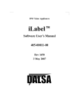
GigE Vision Sapera Application Description
Genie cameras are 100% compliant with the GigE Vision 1.2 and 2.0
specification which defines the communication interface protocol used by any
GigE Vision device. The device description and capabilities are contained in an
XML file. For more information see:
http://www.machinevisiononline.org/public/articles/index.cfm?cat=167
Genie cameras implement a superset of the GenICam™ specification which
defines device capabilities. This description takes the form of an XML device
description file respecting the syntax defined by the GenApi module of the
GenICam™ specification. For more information see www.genicam.org.
The Teledyne DALSA GigE Vision Module provides a license free development platform for Teledyne
DALSA GigE hardware or Sapera vision applications. Additionally supported are Sapera GigE Vision
applications for third party hardware with the purchase of a GigE Vision Module license, or the
Sapera processing SDK with a valid license.
The GigE Vision Compliant XML device description file is embedded within Genie firmware allowing
GigE Vision Compliant applications access to Genie capabilities and controls immediately after
connection.
User’s Sapera
Application
CamExpert
Sapera LT SDK
Network
Configuration Tool
GigE Vision
Module
Images
Control
smart DHCP
Server (optional)
Sapera LT
GigE Server
Sapera
Network
Imaging
Module
Sapera Network
Imaging Driver
GVCP
GigE Vision
Control
Protocol
GVSP
GigE Vision
Stream
Protocol
Genie TS
Package
Camera
Firmware
User
Manuals
Ethernet Network Interface Card
single GigE Vision
Camera
Genie_TS_Series GigE Vision Camera
Alternatively via a switch
To multiple GigE
Vision Cameras
Genie TS Series Overview 11
Camera Specifications Overview
Camera Controls
Synchronization Modes
Free running, External triggered, Software trigger through Ethernet
Exposure Modes
Programmable in increments of 1µs
minimum (in µs) is model specific
maximum is 16 seconds
Pulse controlled via Trigger pulse width.
Trigger Inputs
Opto-isolated, 2.4V to 24V typical, 16mA min.
Debounce range from 0 up to 255 µs
Trigger Delay from 0 to 2,000,000 µs
Strobe Outputs
Output opto-isolated:
Aligned to the start of exposure with a programmable delay, duration and polarity
(using “start of exposure on output line source” feature)
Auto-Iris Control
4-pin auto-iris connector compatible with common DC and video iris lens.
Features
Flat Field Correction
2 Factory FFC plus 2 User Defined FFC (Standard Design Firmware)
3x3 Kernel Sharpening Filter
4 Predefined Selections (Monochrome models with Standard Design Firmware)
LUT
4 LUT available (monochrome models), 1 LUT (color models)
Binning
Digitally based: Horizontal (2 and 4 pixel) and Vertical (2 and 4 line)
(monochrome models)
Gain
Analog (analog gain steps are model dependent) and Digital gain up to 4x
Counter and Timer
1 Counter, and 1 Timer.
User programmable, acquisition independent, with event generation.
Timestamp
1µs internal timer or external signal to timestamp images and events
Metadata Support
Also know as Chunk Data Support in SFNC
Test image
Internal generator with choice of static and shifting patterns, or user defined patterns
uploaded with the file access feature
User settings
Select factory default or either of two user camera configurations
Onboard Memory
Minimum Reserved Data Buffer
256 MB
Reserved Packet Resend Buffer
24 MB default (user defined feature)
Reserved Private User Buffer
4 kB
Total Memory
512 MB
Back Focal Distance
M42 x 1 mount models
12 mm
M42 to Nikon F bayonet adapter
46.5 mm (34.5 mm for the F mount adapter plus 12 mm for the camera body)
M42 to C-Mount adapter
17.52 mm (5.52 mm for the C mount adapter plus 12 mm for the camera body)
CS-mount models
12.52 mm (17.52 mm with a CS to C-mount adapter ring)
Mechanical Interface
Camera Size
49(H) x 49(W) x 54(L) in mm, see “Mechanical Specifications” on page 153
Mass
196 g (no lens)
Power connector
via 25-pin Micro-D connector, or RJ45 in PoE mode
Ethernet connector
RJ45
12 Genie TS Series Overview
Genie_TS_Series GigE Vision Camera
Electrical Interface
Input Voltage
Power Dissipation
Operating Temperature
+12 to +24 Volts DC (+20%/- 10%) at 0.6 Amp minimum
Supports the Power Over Ethernet standard. (PoE Class 3 as per IEEE 802.3af)
< 6W (Vouvray and CMOSIS sensors), < 7W (AnaFocus sensor)
-20 to 60°C
Relative Humidity
5% to 90% non-condensing (operating)
Output Data Configuration
Gigabit Ethernet with PAUSE Frame support (as per IEEE 802.3x)
Data and Control
GigE Vision compliant
Specifications for each available sensor follow this section.
EMI, Shock and Vibration Certifications
Compliance Directives
CE
FCC
RoHS
Standards ID
Overview
EN61000-4-2 : 2008
Electrostatic discharge immunity test
EN61000-4-3 : 2006 A1 : 2007 A2 :
2010
Radiated, radio-frequency, electromagnetic field
immunity test
EN61000-4-4 : 2004
Electrical fast transient/burst immunity test
EN61000-4-5 : 2005
Surge immunity
EN61000-4-6 : 2008
Immunity to conducted disturbances, induced by
radio-frequency fields
EN61000-4-8 : 2009
Power frequency magnetic field immunity
EN61000-4-11 : 2004
Voltage variations immunity
EN61000-6-2 : 2005
Electromagnetic immunity
EN61000-6-4: 2007
Electromagnetic emissions
CISPR 11: 2009 A1 :
group 1 FCC, part 15, subpart B:2010
Limit: class A Conducted Emissions
CISPR 22 : 2008 Limit: class A
LAN port Conducted Emissions
Part 15, class A
Compliancy as per European directive 2004/105/EC
For an image of Genie TS certificates see "EC & FCC Declarations of Conformity" on page 163
Vibration & Shock Tests
Test Levels (while operating)
Test Parameters
Random vibrations
Level 1: 2 grms 60 min.
Level 2: 4 grms 45 min.
Level 3: 6 grms 30 min.
Frequency range: 5 to 2000 Hz
Directions: X, Y, and Z axes
Shocks
Level 1: 20 g / 11 ms
Level 2: 30 g / 11 ms
Level 3: 40 g / 60 ms
Shape: half-sine
Number: 3 shocks (+) and 3 shocks (-)
Directions: ±X, ±Y, and ±Z axes
Additional information concerning test conditions and methodologies is available on request.
Genie_TS_Series GigE Vision Camera
Genie TS Series Overview 13
Sensor Performance: TS-M4096, TS-C4096, TSM3500, TS-C3500, TS-M2500, TS-C2500
The sensor description below (DALSA Vouvray models) provides a specification table and response
graphics. The graph describes the sensor response to different wavelengths of light (excluding lens
and light source characteristics). Visible light spans wavelengths between about 390 - 780
nanometers. Wavelengths below 390 nm are termed ultra-violet while those above 780 nm. are
termed infra-red.
Sensor Specifications
Item / Feature
Specification
Camera Models
TS-M4096, TS-M3500, TS-M2500, TS-C4096, TS-C3500, TS-C2500
Sensor Used
Teledyne DALSA Vouvray
Minimum Frame Rate (internal acquisition)
0.1 fps (one frame every 10 seconds)
Maximum Frame Rate (internal acquisition)
Dependent on Genie TS model (written to internal memory)
For STD and JPEG Designs: 12fps (4096), 19fps (3500), 29fps (2500)
Maximum Frame Rate Output
System dependent on the GigE network
Internal Exposure Control
19 μs to 16 sec. for timed exposure modes
External Exposure Control
External pulse width plus 19 μs (for TriggerWidth exposure mode)
Internal Trigger to Start of Exposure
106 μs minimum
End of Exposure to Readout
20 μs
Horizontal Line Time
26.125 μs (TS-M4096), 22.925 μs (TS-M3500), 16.525 μs (TS-M2500)
26.125 μs (TS-C4096), 22.925 μs (TS-C3500), 16.525 μs (TS-C2500)
Readout Time
Horizontal Line Time (max) x (lines in frame +1) in μs
Pixel Size
6.0µm x 6.0µm
Pixel Format
User selectable 8-bit or 10-bit
Shutter
Full frame electronic shutter
Sensor Gain Range
Default Gain value = 1.0, User selectable 0.7x (multi-slope only), 1.0x,
2.65x (will vary dependant on Black Level Offset setting)
Full Well Capacity
32ke (typical)
Output Dynamic Range † ‡
54.1 db (nominal gain, 8-bit buffer)
55.8 db (nominal gain, 10-bit buffer)
Signal to Noise ratio †† ‡
43.8 db (nominal gain, 8-bit buffer)
44.1 db (nominal gain, 10-bit buffer)
DN Variation
50% saturation: typical +/-4%
Responsivity
16 DN/(nJ/cm2) @ 560 nm (typical)
† Dynamic Range Test Conditions
Analog Gain 1x
Exposure 100µs
All Corrections OFF
†† SNR Test Conditions
Analog Gain 1x
Exposure 1200µs
Factory FFC Active and Defective Pixel Detection Active with threshold at 15%
‡ Specifications calculated according to EMVA-1588 standard, using white LED light
14 Genie TS Series Overview
Genie_TS_Series GigE Vision Camera
Sensor Cosmetic Specifications
The following table lists the current cosmetic specifications for DALSA Vouvray models TS-M4096,
TS-M3500, TS-M2500, TS-C4096, TS-C3500, and TS-C2500.
Blemish Specifications
Hot/Dead Pixel defects †††
Maximum Number of
Defects
Blemish Description
Typical 0.015%
Max 0.05%
Any pixel that deviates by ±20% from the average of
neighboring pixels at 50% saturation including pixel stuck at 0
and maximum saturated value.
none
Grouping of more than 8 pixel defects within a sub-area of 3x3
pixels, to a maximum spot size of 7x7 pixels.
Spot defects
Clusters defects
none
Grouping of more than 5 single pixel defects in a 3x3 kernel.
Column defects
none
Vertical grouping of more than 10 contiguous pixel defects along
a single column.
Row defects
none
Horizontal grouping of more than 10 contiguous pixel defects
along a single row.
Note: All of the sensor cosmetic specifications are with factory flat-field correction (FFC) active.
There are no pre-flat-field camera cosmetic specifications.
††† Test conditions
Factory FFC Active
Defective Pixel Detection OFF
Nominal light = illumination at 50% of saturation
Temperature of camera is 45°C
Genie_TS_Series GigE Vision Camera
Genie TS Series Overview 15
Spectral Responsivity: Monochrome
20.0
Spectral Responsivity
Gain: Analog = 1.0
2
Responsivity (DN/nJ/cm )
15.0
10.0
5.0
0.0
400
450
500
550
600
650
700
750
800
850
900
Wavelength (nm)
Effective Quantum Efficiency: Monochrome
The quantum efficiency graph describes the fraction of photons at each wavelength that contribute
charge to the pixel.
70%
Effective Spectral Quantum Efficiency
Gain: Analog = 1.0
60%
Eff. QE [%]
50%
40%
30%
20%
10%
0%
400
450
500
550
600
650
700
750
800
850
900
Wavelength (nm)
16 Genie TS Series Overview
Genie_TS_Series GigE Vision Camera
Spectral Responsivity: Color
10.0
2
Responsivity (DN/nJ/cm )
Spectral Responsivity
Gain: Analog = 1.0
5.0
0.0
400
450
500
550
600
650
700
750
800
850
900
850
900
Wavelength (nm)
Effective Quantum Efficiency: Color
40%
Effective Spectral Quantum Efficiency
Gain: Analog = 1.0
35%
Eff. QE [%]
30%
25%
20%
15%
10%
5%
0%
400
450
500
550
600
650
700
750
800
Wavelength (nm)
An near infrared cutoff filter (~650nm) is recommended to obtain good visible light color
separation when using light with an IR component. See IR Cutoff Filters.
Genie_TS_Series GigE Vision Camera
Genie TS Series Overview 17
Sensor Performance: TS-M1920, TS-C1920, TSM2048, TS-C2048
The sensor description below (CMOSIS models) provides a specification table and response
graphics. The graph describes the sensor response to different wavelengths of light (excluding lens
and light source characteristics).
Sensor Specifications
Item / Feature
Specification
Camera Models & Sensor Used
TS-M2048, TS-C2048, (CMOSIS — CMV4000)
TS-M1920, TS-C1920, (CMOSIS — CMV2000)
Minimum Frame Rate (internal acquisition)
0.06 fps (one frame every 16.6 seconds)
Maximum Full Frame Rate
(internal acquisition)
(written to internal memory)
with Standard & JPEG Design: 71 fps (TS-M1920), 37 fps (TS-M2048)
with FAST Design: 142 fps (TS-M1920), 75 fps (TS-M2048)
Maximum Frame Rate Output
System dependent on the GigE network
Internal Exposure Control
* using timed exposure modes
14 μs for Standard, JPEG Firmware, — all models
7 μs for Fast Design Firmware, — all supported models
Maximum 16 sec. for all models and firmware.
Internal Trigger to Start of Exposure
0 μs
External Exposure Control
External pulse width plus 13 μs with Standard or JPEG Design Firmware
External pulse width plus 6 μs with Fast Design Firmware
End of Exposure to Start of Readout
Standard Design: 44 μs (for TS-M1920, TS-M2048)
FAST Design: 23 μs (for TS-M1920, TS-M2048)
Horizontal Line Time
Standard Design: 12.9 μs
FAST Design: 6.5 μs
Readout Time
Horizontal Line Time (max) x (lines in frame) — in μs
Pixel Size
5.5 µm x 5.5 µm
Pixel Format
User selectable 8-bit or 10-bit
Shutter
Full frame electronic shutter
Sensor Analog Gain
Default Gain value = 1.2, User selectable 1.2x, 1.4x, or 1.6x
Full Well charge
11.25 ke typical with the default gain value of 1.2
Output Dynamic Range † ‡
57.1 db (nominal gain, 8-bit buffer)
59.7 db (nominal gain, 10-bit buffer)
Signal to Noise ratio †† ‡
38.8 db (nominal gain, 8-bit buffer)
38.9 db (nominal gain, 10-bit buffer)
DN Variation
50% saturation: typical +/-3.5%
Responsivity
see graphic: Spectral Response
18 Genie TS Series Overview
Genie_TS_Series GigE Vision Camera
† Dynamic Range Test Conditions
Exposure 100µs
0% Full Light Level
All Corrections OFF
†† SNR Test Conditions
Exposure 600µs
80% Full Light Level
FFC OFF (no factory FFC provided)
Defective pixels replacement ON with 15%
‡ Specifications calculated according to EMVA-1588 standard, using white LED light
Sensor Cosmetic Specifications
Blemish Specifications
Hot/Dead Pixel defects †††
Maximum Number of
Defects
Blemish Description
Typical 0.0025%
Max 0.005%
Any pixel that deviates by ±20% from the average of
neighboring pixels at 50% saturation including pixel stuck at 0
and maximum saturated value.
none
Grouping of more than 8 pixel defects within a sub-area of 3x3
pixels, to a maximum spot size of 7x7 pixels.
Spot defects
Clusters defects
none
Grouping of more than 5 single pixel defects in a 3x3 kernel.
Column defects
none
Vertical grouping of more than 10 contiguous pixel defects along
a single column.
Row defects
none
Horizontal grouping of more than 10 contiguous pixel defects
along a single row.
††† Test conditions
FFC Off
Defective Pixel Detection OFF
Nominal light = illumination at 50% of saturation
Temperature of camera is 45°C
Genie_TS_Series GigE Vision Camera
Genie TS Series Overview 19
Spectral Response
Models TS-M1920 and TS-M2048 are each available in two versions as listed below. The normal
version sensors are processed on 5µm epi-layer wafers while the E12 version sensors are
processed on 12µm epi-layer wafers. As seen in the following graph, E12 sensors have an
increased spectral response above 600nm.
5µm epi-layer wafer models: G2-GM10-T1921 & G2-GM10-T2041
12µm epi-layer wafer models: G2-GM12-T1921 & G2-GM12-T2041
Models TS-C1920 and TS-C2048 are the color versions standard monochrome versions.
An near infrared cutoff filter (~650nm) is recommended to obtain good visible light color
separation when using light with an IR component. See IR Cutoff Filters.
20 Genie TS Series Overview
Genie_TS_Series GigE Vision Camera
Sensor Performance: TS-M2560
The sensor description below (AnaFocus models) provides a specification table and response
graphics. The graph describes the sensor response to different wavelengths of light (excluding lens
and light source characteristics).
Sensor Specifications
Item / Feature
Specification
Camera Models
TS-M2560
Sensor Used
Lince 5M
Minimum Frame Rate (internal acquisition)
0.06 fps — free-running (one frame every 16.6 seconds)
Maximum Frame Rate (internal acquisition)
51 fps (TS-M2560) (written to internal memory)
Maximum Frame Rate Output
System dependent on the GigE network
Internal Exposure Control
65 μs to 16 sec. for timed exposure modes
Internal Trigger to Start of Exposure
0 μs
External Exposure Control
External pulse width plus 27 μs (TS-M2560 TriggerWidth exposure mode)
End of Exposure to Start of Readout
63 μs (for TS-M2560)
Horizontal Line Time
12.9 μs
Readout Time
Horizontal Line Time (max) x (lines in frame) — in μs
Pixel Size
5 µm x 5 µm
Pixel Format
8-bit
Shutter
Full frame electronic shutter
Sensor Analog Gain
Default Gain value = 1.0 (user selectable 1x. 2x, 4x)
Full Well charge
18 ke (typical)
Output Dynamic Range † ‡
54.9 db (nominal gain, 8-bit buffer)
Signal to Noise ratio †† ‡
41.4 db (nominal gain, 8-bit buffer)
DN Variation
50% saturation: typical +/-3.5%
Responsivity
see graphic:
† Dynamic Range Test Conditions
Exposure 100µs
0% Full Light Level
All Corrections OFF
†† SNR Test Conditions
Exposure 1225µs
80% saturation
All Corrections ON (FPN auto-correction ON, On-sensor Pixel replacement ON (not the same
as median filter)).
‡ Specifications calculated according to EMVA-1588 standard, using white LED light
Genie_TS_Series GigE Vision Camera
Genie TS Series Overview 21
Sensor Cosmetic Specifications
Blemish Specifications
Hot/Dead Pixel defects †††
Spot defects
Maximum Number of
Defects
Blemish Description
Typical 0.0025%
Max 0.005%
Any pixel that deviates by ±20% from the average of
neighboring pixels at 50% saturation including pixel stuck at 0
and maximum saturated value.
none
Grouping of more than 8 pixel defects within a sub-area of 3x3
pixels, to a maximum spot size of 7x7 pixels.
Clusters defects
none
Grouping of more than 5 single pixel defects in a 3x3 kernel.
Column defects
none
Vertical grouping of more than 10 contiguous pixel defects along
a single column.
Row defects
none
Horizontal grouping of more than 10 contiguous pixel defects
along a single row.
††† Test conditions
Defective Pixel Replacement ON
Nominal light = illumination at 50% of saturation
Temperature of camera is 45°C
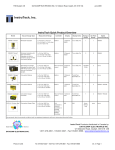
Spectral Response
Model TS-M2560
Measured Fill-Factor x Quantum Efficiency (FF x QE)
22 Genie TS Series Overview
Genie_TS_Series GigE Vision Camera
Sensor Relative Response: VOUVRAY vs. CMOSIS vs.
AnaFocus
The following graphs show the relative sensitivity between sensors, for an equal exposure time and
ignoring sensor signal noise. Two gain factors (nominal and maximum) were used as indicated.
VOUVRAY, ANAFOCUS and CMOSIS sensors response at 1500µs exposure with nominal gain
256
224
194
Signal (DN 8 bits)
192
156
160
118
128
96
64
80
35
52
45
105
87
85
70
64
32
0
4.19
6.25
8.38
10.46
2
Light power (µW/cm )
VOUVRAY Nominal Gain (1.0X)
ANAFOCUS Nominal Gain (1.0X)
CMOSIS Nominal gain (1.2X)
VOUVRAY, ANAFOCUS and CMOSIS sensors response at 1500µs exposure with maximum gain
256
Signal (DN 8 bits)
224
199
192
165
160
146
138
128
125
110
96
64
254
78
39
75
85
45
32
0
4.19
6.25
8.38
10.46
2
Light power (µW/cm )
VOUVRAY Max Gain (2.65X)
Genie_TS_Series GigE Vision Camera
CMOSIS Max gain (1.6X)
ANAFOCUS Max Gain (4.0X)
Genie TS Series Overview 23
Connecting the Genie TS
Camera
GigE Network Adapter Overview
If the computer to be used with the Genie camera does not have a Gigabit network adapter or
second built in Gigabit NIC, a Gigabit Network Interface adapter card (NIC) needs to be installed.
Typically under Windows, the Gigabit NIC is recognized automatically when Windows boots.
With any high performance Gigabit NIC adapter, review the NIC documentation concerning any
special driver required for your specific operating system. When adding a NIC adapter to a
computer, Teledyne DALSA engineering has seen cases where a PCI Express bus Gigabit NIC has
better overall performance than the same NIC hardware in PCI bus format.
PAUSE Frame Support
The Genie TS supports the Gigabit Ethernet PAUSE Frame feature as per IEEE 802.3x. PAUSE
Frame is the Ethernet flow control mechanism that temporarily stops data transmission on the
network. The PAUSE Frame feature can help a NIC that doesn’t have enough buffering to handle
full-speed reception. This requires that the flow control option in the NIC property settings and the
Ethernet switch settings must be enabled.
Note that this problem is not as common with advances in computer bus speeds and memory
sizes. PAUSE Frame support is typically required to manage network traffic within an Ethernet
switch when multiple cameras are simultaneously used. Using PAUSE Frame will require the user to
test various values of Jumbo Frames, to determine the best data throughput. Therefore the
downside to managed network traffic is that the Pause Frame control will reduce the absolute
maximum transfer bandwidth possible on the network.
Connect the Genie TS Camera
Connecting a Genie TS to a network system is independent to whether the Teledyne DALSA Sapera
LT package or a third party GigE Vision development package is used.
Before connecting power to the camera, test all power supplies. Power supplies must meet the
requirements defined in section "Input Signals Electrical " on page 160. Apply power to the
camera.
Connect Genie to the host computer GigE network adapter or to the Ethernet switch via a
CAT5e or CAT6 Ethernet cable. Note: cable should not be less than 1 meter (3 feet) long or
more than 100 meters (328 feet) long.
Once communication with the host computer is started the automatic IP configuration sequence
will assign an LLA IP address as described in section "Genie IP Configuration Sequence" on
page 27, or a DHCP IP address if a DHCP server is present on your network.
Check the diagnostic LED which will be initially red then switch to flashing blue while waiting for
IP configuration. See "Camera Status LED " on page 26 for Genie LED display descriptions.
24 Connecting the Genie TS Camera
Genie_TS_Series GigE Vision Camera
The factory defaults for Genie is Persistent IP disabled and DHCP enabled with LLA always
enabled as per the GigE Vision specification. For additional information see "Genie IP
Configuration Mode Details" on page 150. See the next section "Connectors" on page 25 for an
overview of the Genie interfaces.
Connectors
The Genie has three connectors:
A single RJ45 Ethernet connector for control and video data transmitted to/from the host
computer Gigabit NIC. The Genie TS also supports Power Over Ethernet (PoE). See
"Ruggedized RJ45 Ethernet Cables" on page 173 for secure cables.
A Micro-D sub 25 connector for camera power (or auxiliary power), plus trigger, strobe and
general I/O signals. Teledyne DALSA provides an optional breakout cable (part number G2IOPC-MD25F). See “25-pin Micro-D type Connector Details” on page 158 for connector pinout
specifications.
A 4-pin auto-iris connector pinout compatible with common DC and video iris lens.
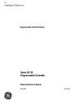
The following figure of the Genie back end shows connector and LED locations. See "Mechanical
Specifications" on page 153 for details on the Genie connectors and camera mounting dimensions.
Genie – Rear View
Genie_TS_Series GigE Vision Camera
Connecting the Genie TS Camera 25
LED Indicators
The Genie has one multicolor LED to provide a simple visible indication of camera state and the
RJ45 Ethernet connector has two LEDs for network status conditions. These are described below.
Network Status Indicators
The Genie TS RJ45 Ethernet connector has two LEDS which display standardized information,
defined as follows:
Ethernet Connector LEDs
Color
Left LED (Connection indicator)
Amber
Off
Right LED (Link/Activity indicator)
Description
Connected to a network
Not Connected to a network
Green
Blinking – There is activity on the port
Off
No data is currently being transferred
Camera Status LED Indicator
The camera is equipped with one LED to display the operational status of the camera. When more
than one condition is active, the LED color indicates the condition with the highest priority (such as
an acquisition in progress has more priority than a valid IP address assignment).
Once the Genie is connected to a network, the Status LED will turn to steady blue when the IP
address is assigned. Only at this time will it be possible by the GigE Server or any application to
communicate with the camera. The following table summarizes the LED states and corresponding
camera status.
LED State
Definition
LED is off
No power to the camera
Steady Red
Initial state on power up before flashing.
Remains as steady Red only if there is a fatal error.
Camera is not initialized **
Flashing Red
Initialization sequence in progress
**
Wait a few minutes for the Genie to reboot itself.
Steady Red + Flashing
Blue
Fatal Error. If the Genie TS does not reboot itself contact Technical Support.
Slow Flashing Blue
Ethernet cable disconnected. The camera continuously attempts to assign
itself an IP address.
Fast Flashing Blue
File Access Feature is transferring data such as a firmware update, FCC or
LUT transfer, etc.
Steady Blue
IP address assigned;
no application connected to the camera
Steady Green
Application connected
Flashing Green
Acquisition in progress. Flashing occurs on frame acquisition but does not
exceed a rate of 100ms for faster frame rates.
Note: Even if the Genie has obtained an IP address, it might be on a different subnet than the NIC it is attached
to. Therefore, if the Genie LED is blue but an application can not see it, this indicates a network configuration
problem. See the troubleshooting section in this manual.
26 Connecting the Genie TS Camera
Genie_TS_Series GigE Vision Camera
LED States on Power Up
The following LED sequence occurs when the Genie is powered up connected to a network with
installed Genie Framework software.
Red
power connected
Flashing Red
initialization
Flashing Blue
waiting for IP
Blue
IP assigned
Green
application
connected
Genie IP Configuration Sequence
The Genie IP (Internet Protocol) Configuration sequence to assign an IP address is executed
automatically on camera power-up or when connected to a network. As a GigE Vision compliant
device, Genie attempts to assign an IP address as follows.
For any GigE Vision device, the IP configuration protocol sequence is:
Persistent IP (if enabled)
DHCP (if a DHCP server is present such as the Teledyne DALSA Smart DHCP server)
Link-Local Address (always enabled)
The factory defaults for Genie is Persistent IP disabled and DHCP enabled with LLA always enabled
as per the GigE Vision specification. For additional information see "Genie IP Configuration Mode
Details" on page 150.
Supported Network Configurations
The Genie obtains an IP address using the Link Local Address (LLA) or DHCP, by default. A LLA IP
address is obtained in about 6 seconds with Microsoft Vista/7 or in about 1 minute with Microsoft
XP. If required, a persistent IP address can be assigned (see "Running the Network Configuration
Tool" on page 33).
Preferably, a DHCP server is present on the network, where the Genie issues a DHCP request for
an IP address. The DHCP server then provides the Genie an IP address. The Teledyne DALSA
Network Configuration tool, installed with the Teledyne DALSA Network Imaging Package, provides
a DHCP server which is easily enabled on the NIC used with the Genie TS (refer to the Teledyne
DALSA Network Imaging Package user's manual).
The LLA method, if used, automatically assigns the Genie with a randomly chosen address on the
169.254.xxx.xxx subnet. After an address is chosen, the link-local process sends an ARP query
with that IP onto the network to see if it is already in use. If there is no response, the IP is
assigned to the device, otherwise another IP is selected, and the ARP is repeated. Note that LLA is
unable to forward packets across routers.
Genie_TS_Series GigE Vision Camera
Connecting the Genie TS Camera 27
Preventing Operational Faults due to ESD
Genie camera installations which do not protect against ESD (electrostatic discharge) may exhibit
operational faults. Problems such as random packet loss, random camera resets, and random loss
of Ethernet connections, may all be solved by proper ESD management.
The Genie camera when used with a simple power supply and Ethernet cable, is not properly
connected to earth ground and therefore is susceptible to ESD caused problems. An Ethernet cable
has no ground connection and a power supply's 0 volt return line is not necessarily connected to
earth ground.
Teledyne DALSA has performed ESD testing on Genie cameras using an 8 kilovolt ESD generator
without any indication of operational faults. The two following methods, either individually or
together will prevent ESD problems.
Method 1: Use a shielded power supply. The Genie case is now properly connected to earth
ground and can withstand ESD of 8 kilovolts, as tested by Teledyne DALSA.
Method 2: When using Power Over Ethernet (PoE), Teledyne DALSA strongly recommends
using a shielded Ethernet cable to provide a ground connection from the controlling
computer/power supply, to the Genie TS. PoE requires a powered computer NIC, or a powered
Ethernet switch, or an Ethernet power injector.
Method 3: Mount the camera on a metallic platform with a good connection to earth ground.
28 Connecting the Genie TS Camera
Genie_TS_Series GigE Vision Camera
Using Genie TS with Sapera API
A Genie camera installation with the Teledyne DALSA Sapera API generally follows the sequence
described below. Detailed installation instructions follow this overview.
Network and Computer Overview
Genie needs to connect to a computer with a GigE network adapter, either built in on the
computer motherboard or installed as a third party PCI adapter. See the previous section
Connecting the Genie TS Camera.
Laptop computers with built in GigE network adapters may still not be able to stream full
frame rates from Genie, especially when on battery power. Thorough testing is required with
any laptop computer to determine the maximum frame rate possible (refer to the Teledyne
DALSA Network Imaging Package user's manual).
Genie also can connect through a Gigabit Ethernet switch. When using VLAN groups, the
Genie and controlling computer must be in the same group (refer to the Teledyne DALSA
Network Imaging Package user's manual).
If Genie is to be used in a Sapera development environment, Sapera LT needs to be
installed, either before or after the Genie software package. If Genie will be used in a GigE
Vision Compliant environment, Sapera or Sapera runtime is not required and you need to follow
the installation instructions of the third party package.
Install the Genie Framework software package if not using a third party GigE Vision
compliant package. Also install Sapera Run-time with CamExpert to control the Genie.
The Windows Firewall exceptions feature is automatically configured to allow the Sapera GigE
Server to pass through the firewall.
Computers with VPN software (virtual private network) may need to have the VPN driver
disabled in the NIC properties. This would be required only on the NIC used with the Genie.
Testing by the user is required.
Once a Genie is connected, look at the small camera icon added to the Windows tray (next to
the clock). Ensure the Genie camera has been found (right click the icon and select Status)
Note that in Windows 7, the icon remains hidden until a camera is connected.
A new Genie installation may require a firmware update. The File Selector feature is used to
select a firmware file. See the CamExpert procedure "File Access via the CamExpert Tool" on
page 148 for additional information.
Use CamExpert (installed either with Sapera or Sapera runtime) to test the installation of the
Genie camera. Set the Genie to internal test pattern. See "Internal Test Image Generator" on
page 117.
Set up the other components of the imaging system such as light sources, camera mounts,
optics, encoders, trigger sources, etc. Test with CamExpert.
Genie_TS_Series GigE Vision Camera
Using Genie TS with Sapera API 29
Sapera LT Library Windows Installation
Note: to install Sapera LT and the Genie device driver, logon to the workstation as an administrator or with an
account that has administrator privileges.
When Sapera application development is performed on the same computer that the Genie is
connected to, the Sapera Development Library (version 7.20 or later, version 7.5 or later to
support JPEG firmware acquisition decoding) must be installed. Else, Sapera LT SDK is not required
to control the Genie camera.
Download the Teledyne DALSA Sapera package or insert the Teledyne DALSA Sapera CD-ROM.
Run the executable file to start the installation.
The installation program will prompt you to reboot the computer.
Continue with the Genie TS Framework Installation described next.
Refer to Sapera LT User’s Manual concerning application development with Sapera.
Genie TS Framework Installation
The Genie TS Framework software package and Sapera runtime provides all components required
to control the Genie with the supplied CamExpert tool. The Genie TS Framework includes the
Network Imaging package (refer to the Teledyne DALSA Network Imaging package manual).
When using a third-party GigE Vision network driver, the Network Imaging package is not required
unless you need to run CamExpert or require access to the Genie TS serial port controllers.
Note: The Teledyne DALSA Sapera CamExpert tool (used throughout this manual to describe Genie TS GigE
Vision features) is installed with either the Sapera LT runtime or the Sapera LT development package. If
Sapera application development is required, install Sapera (7.50 or later for all firmware support) as described
in the previous section.
Procedure
Download the Genie TS Framework package and install the Genie Framework Software which
includes the Network Imaging driver, and the Sapera GigE server.
The procedure will prompt for acceptance of the installation folder for the Genie files.
Optional: If the Teledyne DALSA Sapera LT SDK package is not used, click to install the Genie
TS firmware and user manuals only. Follow the on screen prompts.
Note: With some foreign language Windows there is a problem where the installation of a required filter driver
does not proceed automatically. Until this issue is resolved by Teledyne DALSA engineering, follow the
instructions in Appendix A: Framework Installation Issues with Foreign Language Windows.
30 Using Genie TS with Sapera API
Genie_TS_Series GigE Vision Camera
Camera Firmware Updates or Changes
A Genie TS Framework installation includes the Standard (STD) camera firmware file.
The default folder path is as follows:
[]:\Program Files\Teledyne DALSA\Genie TS\Firmwares\*.cbf
The user can upload new firmware using the File Access Control features as shown by CamExpert.
Alternative firmware designs are available to enable Genie TS cameras with specific features. See
section Genie Firmware Design Versions for descriptions of the firmware design versions supported
by various Genie TS models. The following table lists the current firmware file sets available for the
various Genie TS models, and where the “xx” in the file name denotes the firmware build version.
Current version firmware files are posted on the Teledyne DALSA support web site.
DALSA Vouvray models TS-M4096, TS-M3500, TS-M2500
GenieTS_Mono_Dalsa-5M_8M_12M_STD-Firmware_3CA10.xx.cbf
GenieTS_Mono_Dalsa-5M_8M_12M_JPEG-Firmware_3CA10.xx.cbf
DALSA Vouvray models TS-C4096, TS-C3500, TS-C2500
GenieTS_Color_Dalsa-5M_8M_12M_STD-Firmware_4CA10.xx.cbf
GenieTS_Color_Dalsa-5M_8M_12M_JPEG-Firmware_4CA10.xx.cbf
CMOSIS models TS-M2048, TS-M1920
GenieTS_Mono_Cmosis-2M_4M_STD-Firmware_5CA10.xx.cbf
GenieTS_Mono_Cmosis-2M_4M_JPEG-Firmware_5CA10.xx.cbf
GenieTS_Mono_Cmosis-2M_4M_FAST-Firmware_5CA10.xx.cbf
CMOSIS models TS-C2048, TS-C1920
GenieTS_Color_Cmosis-2M_4M_STD-Firmware_9CA10.xx.cbf
AnaFocus models TS-M2560
GenieTS_Mono_Anafocus-5M_FAST-Firmware_8CA10.xx.cbf
Genie_TS_Series GigE Vision Camera
Using Genie TS with Sapera API 31
Application Development Header Files
Teledyne DALSA provides header files for developers managing Genie TS LUT data and chunk
payload data as supported by GigE Vision 1.2. These files are installed by default in the folder
[drv]:\Program Files\Teledyne DALSA\Genie TS\Developer Support Files\.
These files are:
dalsa_genie_lut.h: Defines the structure for a user LUT data file.
dalsa_genie_chunk_payload.h: Used to capture the raw fields of the extended chunk
metadata from the stream.
dalsa_genie_chunk_extract.h: This is passed the raw chunk data and fills in a data
structure allowing access to the metadata parameters.
For information on extracting image metadata see “Extracting Metadata Stored in a Sapera Buffer”
on page 122 in the Metadata Controls Category.
Note: When developing applications without Sapera LT, request these header files from
Teledyne DALSA.
GigE Server Verification
After a successful Genie TS Framework package installation, the GigE Server icon is visible in the
desktop taskbar tray area (note that in Windows 7 the icon remains hidden until a camera is
connected). After connecting a camera (see following section), allow a few seconds for the GigE
Server status to update. The Genie camera must be on the same subnet as the NIC to be
recognized by the GigE Server.
Device Available
Device IP Error
Device Not Available
The normal GigE server tray
icon when the Genie device is
found. It will take a few seconds
for the GigE Server to refresh
its state after the Genie has
obtained an IP address.
The GigE server tray icon
shows a warning when a device
is connected but there is some
type of IP error.
A red X will remain over the
GigE server tray icon when the
Genie device is not found. This
indicates a major network issue.
Or in the simplest case, the
Genie is not connected.
GigE Server
Tray Icon:
If you place your mouse cursor on this icon, the GigE Server will display the number of GigE Vision
devices found by your PC. Right click the icon and select status to view information about those
devices. See "Running the Network Configuration Tool" on page 33 and "Troubleshooting" on page
175for more information.
32 Using Genie TS with Sapera API
Genie_TS_Series GigE Vision Camera
GigE Server Status
Once the Genie is assigned an IP address (its Status LED is steady blue) the GigE server tray icon
will not have a red X through it, indicating that the Genie device was found. It might take a few
seconds for the GigE Server to refresh its state after the Genie has obtained an IP address.
Right-click the GigE Server tray icon to open the following menu.
Click on Show Status to open a window listing all devices connected to the host system. Each GigE
device is listed by name along with important information such as the assigned IP address and
device MAC address. The screen shot below shows a connected Genie with no networking
problems.
In the event that the device is physically connected, but the Sapera GigE Server icon is indicating
that the connected device is not recognized, click Scan Network to restart the discovery process.
Note that the GigE server periodically scans the network automatically to refresh its state. See
"Troubleshooting" on page 175 for network problems.
Optimizing the Network Adapter used with Genie
Most Gigabit network interface controllers (NIC) allow user modifications to parameters such as
Adapter Buffers and Jumbo Frames. These should be optimized for use with the Genie during the
installation. Refer to the Teledyne DALSA Network Imaging package manual for optimization
information.
Running the Network Configuration Tool
The Network Configuration tool provides information and parameter adjustments for network
adapters installed in the system and any connected GigE Vision camera without use of any
Windows Control Panel application. This tool allows you to:
Activate the Network Imaging driver use for image acquisition on any NIC or disable the
imaging driver for any NIC not used with a GigE Vision camera.
Change the Auto Discovery Interval from the default of 15 seconds.
Verify that the GigE Server is in the Windows firewall exception list.
Configure the NIC and camera IP settings.
Assign a User Defined name to a connected camera.
Assign a Persistent IP address to a camera instead of the default DHCP/LLA assigned address.
Genie_TS_Series GigE Vision Camera
Using Genie TS with Sapera API 33
Easily Configure the NIC as a DHCP server for connected GigE Vision camera.
Important: Changes made with this tool may update Genie parameters stored in flash memory. Do not
remove power from the Genie camera for a minimum 10 seconds.
Refer to the Teledyne DALSA Network Imaging Module manual for more detailed information
on using this tool. As shown below, the Network Configuration tool can quickly verify and modify
the network configuration of the imaging system.
Run the tool from the Windows Start menu: Start•Programs•Teledyne DALSA Sapera Network
Imaging Package•Dalsa Network Configuration Tool. Verify the camera appears as a child of the
NIC card it is connected to. By default the Genie camera is identified by its serial number if no user
defined name has been assigned.
Quick Test with CamExpert
When the Genie TS camera is connected to a Gigabit network adapter on a host computer, testing
the installation with CamExpert is a straightforward procedure.
Start Sapera CamExpert by double clicking the desktop icon created during the Genie software
installation.
CamExpert will search for installed Sapera devices. In the Device list area on the left side, the
connected Genie camera is shown or will be listed in a few seconds after CamExpert completes
the automatic device search (device discovery).
Select the Genie camera device by clicking on the camera user defined name. By default the
Genie camera is identified by its serial number. The Genie status LED will turn green, indicating
the CamExpert application is now connected.
Click on the Grab button for live acquisition (the Genie default is Free Running mode). Focus
and adjust the lens iris. See "Operational Reference" on page 39 for information on CamExpert
parameters with the Genie camera.
34 Using Genie TS with Sapera API
Genie_TS_Series GigE Vision Camera
If the Genie has no lens, just select one of the internal test patterns available (Image Format
Controls – Test Image Selector). All but one are static images to use with the Snap or Grab
function of CamExpert. The single “moving” test image is a shifting diagonal ramp pattern,
which is useful for testing network/computer bandwidth issues. The CamExpert feature
selection and the grabbed pattern are shown below.
Note that CamExpert cannot be used to grab at high frame rates due to it generating an
interrupt for each video frame. The Sapera Grab Demo tool is better suited for high frame
rates.
Refer to the Teledyne DALSA Network Imaging package manual if error messages are shown in
the Output Messages pane. But first, increase the value of the Genie Interpacket Delay feature
available from the GigE Vision Transport Layer Category group in CamExpert. An increase from
default may correct errors with NIC interfaces that do not have adequate performance.
Genie_TS_Series GigE Vision Camera
Using Genie TS with Sapera API 35
About the User Defined Camera Name
The Genie can be programmed with a user defined name to aid identifying multiple cameras
connected to the network. For instance, on an inspection system with 4 cameras, the first camera
might be labeled “top view”, the second “left view”, the third “right view” and the last one “bottom
view”. The factory default user name is set to match the camera serial number for quick initial
identification. Note that the factory programmed Genie TS serial number and MAC address are not
user changeable.
When using CamExpert, multiple Genie TS cameras on the network are seen as different
"Genie_TS-xxxxx" devices as an example. Non Teledyne DALSA cameras are labeled as “GigEVision
Device”. Click on a device user name to select it for control by CamExpert.
An imaging application uses any one of these attributes to identify a camera: its IP address, MAC
address, serial number or User Name. Some important considerations are listed below.
Do not use the camera's IP address as identification (unless it is a persistent IP) since it can
change with each power cycle.
A MAC address is unique to a single camera, therefore the control application is limited to the
vision system with that unique camera if it uses the camera's MAC address.
The User Name can be freely programmed to clearly represent the camera usage. This scheme
is recommended for an application to identify cameras. In this case, the vision system can be
duplicated any number of times with cameras identified by their function, not their serial
numbers or MAC address.
36 Using Genie TS with Sapera API
Genie_TS_Series GigE Vision Camera
Silent Installation of Genie TS Framework
The Genie TS Framework installation can be integrated within a developer's installation procedure.
The silent installation mode allows the Genie Framework installation to proceed without the need
for mouse clicks from a user.
Two steps are required:
Preparation of a response file to emulate a user.
Invoking the Genie Framework installer with command options to use the prepared response
file.
Creating the Response File
An installer response file is created by performing a Genie Framework installation with the
command line switch "-r". The response file is automatically named setup.iss which is saved in the
\windows folder. One simple method is to execute the Framework installer from within a batch file.
The batch file will have one command line.
As an example, using the possible executable file name for the Framework, the command line is:
"Genie_TS_1.00.00.0000 Release.exe" –r
Important: The executable name is enclosed in quotation marks. This is required because of the
space characters in the Genie Framework file name.
Running a Silent Mode Installation
A Genie Framework silent installation, whether done alone or within a larger software installation
requires the Genie Framework executable and the generated response file setup.iss.
Execute the Framework installer with the following command line:
"Genie_TS_1.00.00.0000 Release.exe" -s -f1".\setup.iss"
where in this example, the switch –f1".\setup.iss" specifies that the setup.iss file is in the same
folder as the Framework installer.
Genie_TS_Series GigE Vision Camera
Using Genie TS with Sapera API 37
Windows Embedded 7 Installation
Windows Embedded 7 is not officially supported by Teledyne DALSA due to the number of possible
configurations. However, Sapera LT and other Teledyne DALSA products should function properly
on the Windows Embedded 7 platform provided that the required components are installed.
Teledyne DALSA provides answer files (.xml) for use during Windows Embedded 7 installation that
install all necessary components for running Sapera LT 32-bit or 64-bit versions (SDK or Runtime),
Sapera Processing 32-bit or 64-bit versions (SDK or Runtime), Teledyne DALSA framegrabbers or
Genie GigE Vision devices.
For each platform (32 or 64-bit), the answer file is provided:
SaperaGenie.xml: Configuration for Sapera LT, Sapera Processing and Teledyne DALSA
Genie devices
These files are located in the following directories:
<Install Directory>\Sapera\Install\Win7_Embedded\Win32
<Install Directory>\Sapera\Install\Win7_Embedded\Win64
The OS footprint for these configurations is less than 1 GB. Alternatively, the Windows Thin Client
configuration template provided by Microsoft in the Windows Embedded 7 installation also provides
the necessary dependencies for Sapera LT, Teledyne DALSA framegrabbers and Genie devices
(with an OS footprint of approximately 1.5 GB).
If you are installing other applications on the Windows Embedded 7 platform, it is recommended
that you verify which components are required, and if necessary, create a corresponding Answer
File.
For more information on performing dependency analysis to enable your application on Windows
Embedded 7, refer to the Microsoft Windows Embedded 7 documentation.
38 Using Genie TS with Sapera API
Genie_TS_Series GigE Vision Camera
Operational Reference
Using CamExpert with Genie TS Cameras
The Sapera CamExpert tool is the interfacing tool for GigE Vision cameras, and is supported by the
Sapera library and hardware. When used with a Genie TS camera, CamExpert allows a user to test
most of the operating modes. Additionally CamExpert saves the Genie user settings configuration
to the camera or saves multiple configurations as individual camera parameter files on the host
system (*.ccf).
An important component of CamExpert is its live acquisition display window which allows
immediate verification of timing or control parameters without the need to run a separate
acquisition program.
Click on any parameter and a short description is displayed below the Category pane. The same
context sensitive help is available by clicking on the
configuration parameter. Click on the
information on CamExpert.
button then click on a camera
button to open the help file for more descriptive
CamExpert Panes
The various areas of the CamExpert tool are described in the summary figure below. GigE Vision
device Categories and Parameter features are displayed as per the device’s XML description file.
The number of parameters shown is dependent on the View mode selected (Beginner, Expert, Guru
– see description below).
Genie_TS_Series GigE Vision Camera
Operational Reference 39
Device pane: View and select from any installed GigE Vision or Sapera acquisition device.
After a device is selected CamExpert will only present parameters applicable to that device.
Parameters pane: Allows viewing or changing all acquisition parameters supported by the
acquisition device. CamExpert displays parameters only if those parameters are supported by
the installed device. This avoids confusion by eliminating parameter choices when they do not
apply to the hardware in use.
Display pane: Provides a live or single frame acquisition display. Frame buffer parameters are
shown in an information bar above the image window.
Control Buttons: The Display pane includes CamExpert control buttons. These are:
40 Operational Reference
Genie_TS_Series GigE Vision Camera
Acquisition control button:
Click once to start live grab, click again to stop.
Single frame grab:
Click to acquire one frame from device.
Software trigger button:
With the I/O control parameters set to Trigger Enabled / Software Trigger
type, click to send a single software trigger command.
CamExpert display controls:
(these do not modify the frame buffer data)
Stretch (or shrink) image to fit, set image display to original size, or zoom
the image to any size and ratio. Note that under certain combinations of
image resolution, acquisition frame rate, and host computer speed, the
CamExpert screen display may not update completely due to the host CPU
running at near 100%. This does not affect the acquisition.
Histogram / Profile tool:
Select to view a histogram or line/column profile during live acquisition.
Output pane: Displays messages from CamExpert or the GigE Vision driver.
CamExpert View Parameters Option
All camera features have a Visibility attribute which defines its requirement or complexity. The
states vary from Beginner (features required for basic operation of the device) to Guru (optional
features required only for complex operations).
CamExpert presents camera features based on their visibility attribute. CamExpert provides quick
Visibility level selection via controls below each Category Parameter list [ << Less More>> ]. The
user can also choose the Visibility level from the View ∙ Parameters Options menu.
Camera Information Category
Camera information can be retrieved via a controlling application. Parameters such as camera
model, firmware version, etc. are read to uniquely identify the connected Genie device. These
features are typically read-only. GigE Vision applications retrieve this information to identify the
camera along with its characteristics.
The Camera Information Category groups information specific to the individual GigE Vision camera.
In this category the number of features shown are identical whether the view is Beginner, Expert,
or Guru.
Features listed in the description table but tagged as Invisible are usually for Teledyne DALSA or
third party software usage—not typically needed by end user applications. Also important, Genie
TS cameras are available in a number of models implementing different sensors and image
resolutions which may not support the full feature set defined in this category.
Genie_TS_Series GigE Vision Camera
Operational Reference 41
Camera Information Feature Descriptions
The following table describes these parameters along with their view attribute and in which device
version the feature was introduced. Additionally the Device Version column will indicate which
parameter is a member of the DALSA Features Naming Convention (using the tag DFNC), versus
the GenICam Standard Features Naming Convention (SFNC not shown).
New features for a major device version release will be indicated by green text for easy
identification.
42 Operational Reference
Genie_TS_Series GigE Vision Camera
Display Name
Feature & Values
Description
Manufacturer Name
DeviceVendorName
Displays the device vendor name. (RO)
1.00
Beginner
Model Name
DeviceModelName
Displays the device model name. (RO)
1.00
Beginner
Device Version
DeviceVersion
Displays the device version. This tag will also
highlight if the firmware is a beta or custom design.
(RO)
1.00
Beginner
Manufacturer Info
DeviceManufacturerInfo
This feature provides extended manufacturer
information about the device. Genie TS cameras show
which firmware design is currently loaded. (RO)
1.00
Beginner
Firmware Version
DeviceFirmwareVersion
Displays the currently loaded firmware version
number. Firmware files have a unique number and
have the .cbf file extension. (RO)
1.00
Beginner
Serial Number
DeviceID
Displays the device’s factory set camera serial
number. (RO)
1.00
Beginner
MAC Address
deviceMacAddress
Displays the unique MAC (Media Access Control)
address of the Device. (RO)
1.00
DFNC
Beginner
Device User ID
DeviceUserID
Feature to store a user-programmable identifier of up
to 15 characters. The default factory setting is the
camera serial number. (RW)
1.00
Beginner
Device Temperature
Selector
DeviceTemperatureSelector
Select the source where the temperature is read.
1.11
Beginner
FPGA Board
FPGABoard
Sensor Board
SensorBoard
Device Version
& View
Read FPGA Board temperature
Read Sensor Board temperature
Device Temperature
DeviceTemperature
The temperature of the selected source in degrees
Celsius
1.11
Beginner
Power-up Configuration
Selector
UserSetDefaultSelector
Selects the camera configuration set to load and
make active on camera power-up or reset. The
camera configuration sets are stored in camera
non-volatile memory. (RW)
1.00
Beginner
Factory Setting
Default
UserSet1
UserSet1
Select the user defined configuration UserSet 1 as the
Power-up Configuration.
UserSet2
UserSet2
Select the user defined configuration UserSet 2 as the
Power-up Configuration.
User Set Selector
UserSetSelector
Load factory default feature settings.
Selects the camera configuration set to load feature
settings from or save current feature settings to. The
Factory set contains default camera feature settings.
(RW)
Factory Setting
Default
UserSet 1
UserSet1
Select the User Defined Configuration space UserSet1
to save to or load from features settings previously
saved by the user.
UserSet 2
UserSet2
Select the User Defined Configuration space UserSet1
to save to or load from features settings previously
saved by the user.
1.00
Beginner
Select the default camera feature settings saved by
the factory.
Load Configuration
UserSetLoad
Loads the camera configuration set specified by the
User Set Selector feature, to the camera and makes it
active. Can not be updated during a Sapera transfer.
(W)
1.00
Beginner
Save Configuration
UserSetSave
Saves the current camera configuration to the user
set specified by the User Set Selector feature. The
user sets are located on the camera in non-volatile
memory. (W)
1.00
Beginner
Genie_TS_Series GigE Vision Camera
Operational Reference 43
Device Built-In Self Test
deviceBIST
Command to perform an internal test which will
determine the device status. (W)
1.00
DFNC
Beginner
Device Built-In Self Test
Status
deviceBISTStatus
Return the status of the device Built-In Self test.
Possible return values are device-specific.
1.00
Beginner
Passed
Passed
Firmware update failed
FirmwareUpdateFailure
FPGA Cyclic Redundancy
Check Failed
FPGA_CRC_Failure
Unexpected Error
Unexpected_Error
No failure detected
Last firmware update operation failed.
FPGA cyclic redundancy check failed.
Switched to recovery mode due to unexpected
software error.
Device Built-In Self Test
Status All
deviceBISTStatusAll
Return the status of the device Built-In Self Test as a
bitfield. The meaning for each bit is device-specific.
1.10
DFNC
Beginner
Device Reset
DeviceReset
Resets the device to its power up state. (W)
1.00
Beginner
Calibration Date
deviceCalibrationDateRaw
Date when the camera was calibrated.
1.11
DFNC
Invisible
Device Acquisition Type
deviceAcquisitionType
Displays the Device Acquisition Type of the product.
(RO)
1.00
DFNC
Invisible
Sensor
Device TL Type
Sensor
DeviceTLType
GigE Vision
The device gets its data directly from a sensor.
Transport Layer type of the device.
GigEVision
GigE Vision Transport Layer
1.20
Invisible
Device TL Version Major
DeviceTLVersionMajor
Major version of the device’s Transport Layer.
1.20
Invisible
Device TL Version Minor
DeviceTLVersionMinor
Minor version of the device’s Transport Layer.
1.20
Invisible
DFNC Major Rev
deviceDFNCVersionMajor
Major revision of Dalsa Feature Naming Convention
which was used to create the device’s XML. (RO)
1.00
DFNC
Invisible
DFNC Minor Rev
deviceDFNCVersionMinor
Minor revision of Dalsa Feature Naming Convention
which was used to create the device’s XML. (RO)
1.00
DFNC
Invisible
SFNC Major Rev
DeviceSFNCVersionMajor
Major Version of the Standard Features Naming
Convention which was used to create the device's
XML. (RO)
1.00
Invisible
SFNC Minor Rev
DeviceSFNCVersionMinor
Minor Version of the Standard Features Naming
Convention which was used to create the device's
XML. (RO)
1.00
Invisible
SFNC SubMinor Rev
DeviceSFNCVersionSubMinor
SubMinor Version of the Standard Features Naming
Convention which was used to create the device's
XML. (RO)
1.00
Invisible
44 Operational Reference
Genie_TS_Series GigE Vision Camera
Camera Configuration Selection Dialog
CamExpert provides a dialog box which combines the features to select the camera power up state
and for the user to save or load a camera state from Genie memory.
Camera Power-up Configuration
The first drop list selects the camera configuration state to load on power-up (see feature
UserSetDefaultSelector). The user chooses from one factory data set or one of two possible user
saved states.
User Set Configuration Management
The second drop list allows the user to change the camera configuration anytime after a power-up
(see feature UserSetSelector). To reset the camera to the factory configuration, select Factory
Setting and click Load. To save a current camera configuration, select User Set 1 or 2 and click
Save. Select a saved user set and click Load to restore a saved configuration.
Genie_TS_Series GigE Vision Camera
Operational Reference 45
Sensor Control Category
The Genie TS sensor controls, as shown by CamExpert, groups sensor specific parameters. This
group includes controls for frame rate, exposure time, auto-brightness controls (exposure and
gain), and the multi-slope function. Parameters in gray are read only, either always or due to
another parameter being disabled. Parameters in black are user set in CamExpert or programmable
via an imaging application.
Features listed in the description table but tagged as Invisible are usually for Teledyne DALSA or
third party software usage—not typically needed by end user applications. Also important, Genie
TS cameras are available in a number of models implementing different sensors and image
resolutions which may not support the full feature set defined in this category.
46 Operational Reference
Genie_TS_Series GigE Vision Camera
Sensor Control Feature Descriptions
The following table describes these features along with their view attribute and device framework version. For each feature the device version
may differ for each camera sensor available and whether the camera is programmed with Standard firmware (STD), JPEG firmware (JPG), or
Fast firmware (FST). Such differences will be clearly indicated for any applicable feature.
When a Device Version number is indicated, this represents the camera software functional group, not a firmware revision number. As Genie
TS capabilities evolve the device version will increase, therefore identifying the supported function package. New features for a major device
version release will be indicated by green text for easy identification.
The first column indicates whether a feature applies to monochrome or color camera models via a symbol. No symbol indicates a common
feature. Additionally the description column will indicate which feature is a member of the DALSA Features Naming Convention (DFNC),
versus the GenICam Standard Features Naming Convention (SFNC not shown).
B/W
Color
Display Name
Feature & Values
Description
Device Scan Type
DeviceScanType
Defines the scan type of the device’s sensor.
Genie TS is an Areascan camera.
< RO, Beginner >
Areascan
Sensor Color Type
Areascan
sensorColorType
Monochrome
Bayer Sensor
CFA_Bayer
Input Pixel Size
pixelSizeInput
CMOSIS
CMV xx
AnaFocus
Lince 5M
All Designs
All Designs
All Designs
all
all
Device uses an Areascan sensor.
Defines the camera sensor color type.
< RO, DFNC, Beginner >
Monochrome Sensor
Vouvray
DALSA
Sensor color type is monochrome.
all
Sensor color type is Bayer Color Filter Array (CFA).
Size of the image input pixels, in bits per pixel.
< RO, DFNC, Guru >
8 Bits/Pixel
Bpp8
10 Bits/Pixel
Bpp10
Sensor output data path is 8 bits per pixel.
—
—
FAST
Sensor output data path is 10 bits per pixel.
all
all
—
Sensor Width
SensorWidth
Defines the sensor width in active pixels.
< RO, Expert >
all
all
all
Sensor Height
SensorHeight
Defines the sensor height in active lines.
< RO, Expert >
all
all
all
Acquisition Frame Rate
AcquisitionFrameRate
Specifies the camera internal frame rate, in Hz.
Any user entered value is automatically adjusted to a
valid camera value. Note that a change in frame rate
takes effect only when the acquisition is stopped and
restarted.
< Beginner >
all
all
all
V1.10 - all
all
all
Auto-Brightness Mode
autoBrightnessMode
Off
Genie_TS_Series GigE Vision Camera
Sets the mode for the Auto-Brightness function.
< DFNC Expert >
Off
Disable the auto-brightness mode.
Operational Reference 47
Active
Auto-Brightness Sequence
Active
autoBrightnessSequence
Activates the auto-brightness mode when the
AcquisitionStart or AcquisitionArm command is received.
Specifies the processing order for the auto-brightness
algorithm. Gain, Iris, and Exposure are adjusted
sequentially, in the selected order, to achieve the autobrightness target value. If the Iris, Gain, or Exposure
features are not available or disabled, that feature is
ignored in the processing sequence.
< DFNC Expert >
Exposure \ Gain
Exposure_Gain_Iris
Adjust Exposure, Gain, Iris, in that order to achieve the
auto-brightness target value.
Gain \ Exposure
Gain_Exposure_Iris
Adjust Gain, Exposure, Iris, in that order, to achieve the
auto-brightness target value.
Auto-Brightness Target Source
autoBrightnessTargetSource
Specifies the source image color plane(s) used by the
Auto-Brightness algorithm to determine the brightness
adjustment required to obtain the auto-brightness target
value.
< DFNC Expert >
Luminance
Luminance
Raw Bayer Pattern
RawBayerPattern
Auto-Brightness Target
autoBrightnessTarget
Auto-Brightness Target
Variation
autoBrightnessTargetRangeVariation
Auto-Brightness Algorithm
autoBrightnessAlgorithm
Average
Histogram Windowing
Average
HistogramWindowing
V1.10 - all
all
V1.10 - all
all
all
The luminance or Y component of the image is used as
the auto-brightness target source.
all
The Raw Bayer Pattern of the image is used as the autobrightness target source.
—
Sets the target image grayscale value, in DN, for the
auto-brightness algorithm. Features that use autobrightness include ExposureAuto, GainAuto, and
IrisAuto.
< DFNC Expert >
V1.10 - all
all
all
Sets the auto-brightness target Range Variation in (DN).
An autoBrightnessTarget value within this range is
considered valid and will not be compensated.
< DFNC Expert >
V1.10 - all
all
all
Specifies the auto-brightness algorithm used to calculate
the brightness in the target image source plane(s).
< DFNC Expert >
V1.10 - all
The auto-brightness algorithm calculates the average
luminance from the camera image and determines if the
brightness should increase or decrease based on the
requested target brightness.
all
all
The auto-brightness algorithm calculates the histogram
in every image from the camera and determines if the
brightness should increase or decrease based on the
requested target brightness.
V1.11 – STD
V1.20 - JPG
—
Auto-Brightness Histogram
Windowing Lower Boundary
autoBrightnessAlgoHistogram
WindowingLowerBoundary
Specify the lower area boundary (in percent) of the
histogram data range, used to reach the target value.
< DFNC Expert >
V1.10 – STD
V1.11 – STD
—
Auto-Brightness Histogram
Windowing Upper Boundary
autoBrightnessAlgoHistogram
WindowingUpperBoundary
Specify the upper area boundary (in percent) of the
histogram data range, used to reach the target value.
< DFNC Expert >
V1.10 – STD
V1.11 – STD
—
48 Operational Reference
Genie_TS_Series GigE Vision Camera
Auto-Brightness Minimum Time
Activation
Auto-Brightness Convergence
Time
autoBrightnessAlgoMinTimeActivation
autoBrightnessAlgoConvergenceTime
Auto-Brightness ROI Selector
autoBrightnessROISelector
Auto-Brightness ROI 1
Auto-Brightness ROI Mode
autoBrightnessROI1
autoBrightnessROIMode
Off
Active
Active
autoBrightnessROIWidth
Auto-Brightness ROI Height
autoBrightnessROIHeight
Auto-Brightness
ROI Offset X
autoBrightnessROIOffsetX
Auto-Brightness
ROI Offset Y
autoBrightnessROIOffsetY
Auto-Exposure
ExposureAuto
Off
Off
Continuous
Continuous
Genie_TS_Series GigE Vision Camera
all
all
all
Specifies the approximate maximum time the
autoBrightnessAlgorithm should take to compensate the
image brightness as defined by the
autoBrightnessTarget. Actual times typically are less but
may be somewhat more.
< DFNC Expert >
all
all
all
Selects the processing ROI for the Auto-Brightness
algorithm.
< DFNC Expert >
all
all
all
all
all
all
Specifies the ROI width for the currently selected AutoBrightness ROI.
< DFNC Expert >
all
all
all
Specifies the ROI height for the currently selected AutoBrightness ROI.
< DFNC Expert >
all
all
all
Specifies the ROI offset from the image origin along the
X-axis for the currently selected
Auto-Brightness ROI.
< DFNC Expert >
all
all
all
Specifies the ROI offset from the image origin along the
Y-axis for the currently selected
Auto-Brightness ROI.
< DFNC Expert >
all
all
all
Sets the automatic exposure mode when the
ExposureMode feature is set to Timed.
< Expert >
all
all
all
ROI 1
Activates the ROI specified by the Auto-Brightness ROI
Selector. When active, the Auto-Brightness algorithm
limits analysis to this ROI image area to determine the
auto-brightness adjustments. By default the AutoBrightness ROI Mode is set to Off.
< DFNC Expert >
Off
Auto-Brightness ROI Width
Specifies the time delay between an image brightness
change from the autoBrightnessTarget and when
compensation of Gain/Exposure/Iris starts. This
eliminates repetitive adjustments of short term
brightness variations.
< DFNC Expert >
The output image is used in the Auto-Brightness
algorithm.
The selected ROI is used in the auto-brightness
algorithm.
Exposure duration is manually controlled using the
ExposureTime feature.
Exposure duration is constantly adapted by the camera
to meet the auto-brightness target pixel value. The initial
starting exposure can be set by setting ExposureAuto to
Off, changing the exposure time and then setting it back
to Continuous.
Operational Reference 49
Auto-Exposure Time Min Value
exposureAutoMinValue
Sets the minimum exposure time value allowed by the
user, in microseconds, for the Auto-Exposure function.
< DFNC Expert >
all
all
all
Auto-Exposure Time Max Value
exposureAutoMaxValue
Sets the maximum exposure time value allowed by the
user, in microseconds, for the Auto-Exposure function.
< DFNC Expert >
all
all
all
Exposure Mode
ExposureMode
Sets the operation mode for the camera’s exposure (or
shutter).
< Beginner >
all
all
all
all
all
all
Timed
Timed
Trigger Width
TriggerWidth
Exposure Alignment
exposureAlignment
The exposure duration time is set using the Exposure
Time feature and the exposure starts with aFrameStart
event.
Uses the width of the trigger signal pulse to control the
exposure duration. Use the Trigger Activation feature to
set the polarity of the trigger. The Trigger Width setting
is applicable with the Trigger Selector feature set to
Framestart.
Note that the Line Inverter feature setting may affect the
polarity of the trigger signal and is only available when
exposureAlignment = Reset.
Exposure Alignment specifies how the exposure is
executed in relationship to the sensor capabilities and
current frame trigger.
< DFNC Beginner >
Synchronous
Synchronous
Exposure is synchronous to the internal timing of the
sensor. The readout is concurrent to the exposure for the
fastest possible frame rate. When a valid trigger is
received and the ExposureTime is shorter than the
readout period, the ExposureStart event is latched in the
previous frame’s readout. That is; the
ExposureStartEvent is delayed and is initiated when the
actual exposure starts such that the exposure ends and
readout begins as soon as the previous readout has
completed.
Reset
Reset
Sensor timing is reset to initiate exposure when a valid
trigger is received. Readout is sequential to exposure,
reducing the maximum achievable frame rates. That is, a
trigger received during exposure or readout is ignored
since data would be lost by performing a reset.
Synchronous_EOE
Synchronous_EOE
50 Operational Reference
This mode is similar to the standard Synchronous mode
described above. The difference being that this mode
requires a continuous and fixed frequency trigger and is
used with the Auto-Brightness or Auto-Exposure modes.
The readout occurs only at the end of exposure. Use
ExposureTimeMaxValue to define the maximum possible
exposure time which is followed by the frame readout.
This mode is used to synchronize readouts of multiple
cameras having independent variable exposures.
Genie_TS_Series GigE Vision Camera
Reset_EOE
Reset_EOE
Exposure Delay
exposureDelay
This mode is similar to the standard Reset mode
described above. The difference being that this mode
requires a continuous and fixed frequency trigger and is
used with the Auto-Brightness or Auto-Exposure modes.
The readout occurs only at the end of exposure. Use
ExposureTimeMaxValue to define the maximum possible
exposure time which is followed by the frame readout.
This mode is used to synchronize readouts of multiple
cameras having independent variable exposures.
Specifies the delay in microseconds (µs) to apply after
the FrameStart event before starting the
ExposureStart event.
< DFNC Beginner >
all
all
all
Exposure Time
ExposureTime
Sets the exposure time (in microseconds) when the
Exposure Mode feature is set to Timed.
< Beginner >
all
all
all
Exposure Time Max Value
exposureTimeMaxValue
User set maximum exposure time possible between
continuous triggers, when exposureAlignment is set to
Synchronous_EOE or Reset_EOE.
< DFNC Expert >
all
all
all
Selects which gain is controlled when adjusting
gain features.
< Beginner >
all
all
all
Apply a digital gain adjustment to the red component.
V1.20
V1.20
—
Apply a digital gain adjustment to the green component.
V1.20
V1.20
—
Apply a digital gain adjustment to the blue component.
V1.20
V1.20
—
Sets the selected gain as an amplification factor applied
to the image.
< Beginner >
all
all
all
Controls the state of the automatic gain control.
< Beginner >
all
all
all
all
all
all
Gain Selector
GainSelector
Analog
AnalogAll
Apply an analog gain adjustment within the sensor to the
entire image.
Digital
DigitalAll
Apply a digital gain adjustment to the entire image.
DigitalRed
DigitalRed
DigitalGreen
DigitalGreen
DigitalBlue
DigitalBlue
Gain
Gain
Automatic Gain Control
GainAuto
Off
Off
Continuous
Continuous
Auto-Gain Max Value
Genie_TS_Series GigE Vision Camera
gainAutoMaxValue
Gain is manually controlled using the Gain feature.
Gain is constantly adjusted by the camera to meet the
auto-brightness target pixel value. The initial starting
gain can be set by setting GainAuto to Off, changing the
gain value and then setting it back to Continuous.
Sets the maximum gain multiplier value for the
automatic gain algorithm. The automatic gain function is
an amplification factor applied to the video signal to
obtain the auto-brightness target value.
< DFNC Expert >
Operational Reference 51
Auto-Gain Min Value
gainAutoMinValue
Black Level Selector
Sets the minimum gain multiplier value for the automatic
gain algorithm. The automatic gain function is an
amplification factor applied to the video signal to obtain
the auto-brightness target value.
< DFNC Expert >
BlackLevelSelector
AnalogAll
BlackLevel
Auto-Black Level
all
all
all
all
all
Controls the black level as an absolute physical value.
This represents a DC offset applied to the video signal, in
DN (digital number) units. The Black Level Selector
feature specifies the channel to adjust.
< Beginner >
all
all
—
Enable the automatic black level adjustment function
and how it operates.
< Expert >
—
—
V1.xx
Selects which Black Level to adjust using the
Black Level features.
< Beginner >
Analog
Black Level
all
BlackLevelAuto
Sensor Dark Offset
Off
Off
On Demand
OnDemand
Function operates on BlackLevelAutoOnDemandCmd
Function Off
Continuous
Continuous
Function operates continuously
Auto-black Level On-Demand
Command
BlackLevelAutoOnDemandCmd
Enables an automatic black level adjustment process.
< Expert >
Automatic Black Level
Calibration Status
BlackLevelAutoCalibrationStatus
Returns the current state of black level calibration.
< Expert >
Calibrated
UnCalibrated
On-Sensor FPN Calibration Mode
Calibrated
UnCalibrated
OnSensorFpnCalibrationMode
Off
Off
OnDemand
Continuous
Continuous
On-Sensor FPN Calibration OnDemand Comand
OnSensorFpnCalibrationOnDemandCmd
On-Sensor FPN Calibration
Status
OnSensorFpnCalibrationStatus
Calibrated
Calibrated
UnCalibrated
MultiSlope Sensor Response
Mode
multiSlopeSensorResponseMode
Off
52 Operational Reference
V1.xx
—
—
V1.xx
FPN calibration Off
FPN calibration On Demand
FPN calibration Continuous
Enable an automatic On-Sensor Fixed Pattern Noise
Calibration process.
< Expert >
V1.xx
—
—
V1.xx
V1.10 - STD
all
—
The fixed pattern noise is calibrated
The fixed pattern noise is not calibrated
Sets the enable state of the multi-slope response
mechanism on the sensor.
< DFNC Expert >
Off
—
The black level is not calibrated.
Returns the current state of the fixed pattern noise
calibration process.
< Expert >
UnCalibrated
—
The black level is calibrated.
Activation mode for the On-Sensor Fixed Pattern Noise
Calibration function.
< Expert >
On Demand
V1.xx
Disable the MultiSlopeSensorResponseMode feature.
Genie_TS_Series GigE Vision Camera
Active
MultiSlope Knee Selector
Active
multiSlopeKneeSelector
Enable the MultiSlopeSensorResponseMode feature.
Selects which multi-slope knee position to set.
< DFNC Expert >
Knee Point 1
KneePoint1
Selects the first knee point.
Knee Point 2
KneePoint2
Selects the second knee point.
V1.10 - STD
all
—
MultiSlope Knee Position X
multiSlopeKneePositionX
Sets the Multi-Slope Knee position as a % of the
exposure time.
< DFNC Expert >
V1.10 - STD
all
—
MultiSlope Knee Position Y
multiSlopeKneePositionY
Sets the Multi-Slope Knee position as a % of the
saturated luminance output.
< DFNC Expert >
V1.10 - STD
all
—
Acquisition Frame Rate (Raw)
AcquisitionFrameRateRaw
Controls the desired frame rate of the camera
in .001 Hz.
< Invisible >
all
all
all
Black Level RAW
BlackLevelRaw
Controls the black level as an absolute physical value.
< Invisible >
all
all
—
Auto-Brightness Algorithm
Source
autoBrightnessAlgoSource
Specifies the source location of the Auto-Brightness
algorithm.
< Invisible >
all
all
all
Host computer IP address where the algorithm TCP
server is run.
< Invisible >
all
all
all
Host computer IP port where the algorithm TCP server is
run.
< Invisible >
all
all
all
Local
Local
The auto-brightness algorithm runs in the camera.
Ethernet
Host
The auto-brightness algorithm runs on a host machine
via the Ethernet connection.
DEV - Auto-Brightness
Algorithm IP Address
autoBrightnessAlgoHostIPAddress
DEV - Auto-Brightness
Algorithm IP Port
autoBrightnessAlgoHostIPPort
Genie_TS_Series GigE Vision Camera
Operational Reference 53
Bayer Mosaic Pattern
The Genie TS Color camera outputs raw Bayer image data using the mosaic pattern shown below.
Teledyne DALSA Sapera CamExpert tool interprets the raw Bayer output when the user enables the
Pre-Processing Software Bayer Decoder.
Bayer Mosaic Pattern and the CamExpert processing function to decode the Genie TS Color
Gain and Black Level Control Details
The Genie TS series of cameras provide gain and black level adjustments. Dependent on the model
of camera, adjustments are available at the sensor as an analog variable and/or in the digital
domain. The gain and black level controls can make small compensations to the acquisition in
situations where lighting varies and the lens iris can not be easily adjusted. Optimal gain and black
level adjustments maximizes the Genie TS dynamic range for individual imaging situations. The
user can evaluate Gain and Black Level by using CamExpert.
Features and limitations are described below.
Black Level offset is expressed as a digital number providing a +/- offset from the factory
setting. The factory setting optimized the black level offset for maximum dynamic range under
controlled ideal dark conditions.
Analog Gain is expressed as a multiplication factor applied at the sensor level, before any FFC.
The increased gain increases the sensor dynamic range but with a non-proportional increase in
noise.
For each setting of analog gain, the sensor data has applied a unique Factory set Flat Field
Correction, to ensure uniform pixel response. which is applied after the analog gain stage but
before the digital gain stage.
When any Flat Field Correction is applied, the resulting gain multiplying factor is increased
based on the FFC calibration. As an example with Genie TS-12M with FFC Active and default
Black Offset, with an analog gain set to 2.65, the resulting multiplying factor is 2.75.
Digital Gain is expressed as a multiplication factor applied after the Analog Gain and any FFC
stages, but note that increasing digital gain does not increase the low level resolution and
increases the sensor noise proportionately.
54 Operational Reference
Genie_TS_Series GigE Vision Camera
Exposure Controls Details
Exposure Control modes define the method and timing of controlling the sensor integration period.
The integration period is the amount of time the sensor is exposed to incoming light before the
video frame data is transmitted to the controlling computer.
Exposure control is defined as the start of exposure and exposure duration.
The feature Exposure Mode selects the controlling method for the exposure.
The start of exposure can be driven by an internal timer signal, an external trigger signal, or a
software function call.
The exposure duration can be programmable (such as the case of an internal timer) or
controlled by the external trigger pulse width (when the feature ExposureMode = TriggerWidth)
as shown in the following graphic.
Internal Programmable Exposure
The Genie TS in an Internal Programmable Exposure mode has the following features:
Programmable internal trigger, where the maximum and minimum sensor frame rate limits are
defined by the ExposureTime feature.
Exposure synchronization timing is "Synchronous Mode" (on page 57) where the exposure is
aligned with the sensor horizontal line timing and the next acquisition is triggered by an
internal programmable timer.
Exposure duration is user programmable (exposure maximum is dependent on the frame rate).
Minimum exposure (in µs) is model dependent.
Image readout is simultaneous where the grabbed image frame is readout during the next
frame exposure time. This allows for fastest possible frame rates. See the timing diagram
below.
Example Timing:
Free-running Exposure Timing
Genie_TS_Series GigE Vision Camera
Operational Reference 55
External Trigger Programmable Exposure
Also known as “Edge Pre-select” exposure. See the timing diagram below.
An external trigger edge initiates the exposure process.
The user programmable delay (exposureDelay) from valid trigger edge to start of exposure is
camera model specific.
Supports "Synchronous Mode" (on page 57) timing for fastest possible frame rates. Start of
exposure is aligned on the next horizontal line while the exposure duration period is in 1µs
steps. Exposure and sensor readout can be concurrent.
Supports "Reset Mode" (on page 57) timing. Exposure duration is in 1µs steps. Exposure and
sensor readout must be sequential, limiting the maximum frame rate.
Exposure duration is programmable from the model dependent minimum to 16 seconds (in 1μs
steps).
Any external trigger received before the last exposure is ignored.
Example Timing
FrameTrigger Inactive
FrameTrigger Inactive
FrameTrigger Active
Frame Inactive
Frame Inactive
Exposure
Delay
Exposure(1)
ReadOut (1)
Exposure
Delay
Exposure(2)
ReadOut (2)
Programmable Synchronous Mode Exposure Timing
exposureAlignment=Reset
Input Signal
Event
TriggerDelay
Input Signal
Event (2)
ValidFrameTrigger
Event
Invalid Frame Trigger Period
FrameTrigger Inactive
FrameTrigger Active
FrameActive (1)
Frame Inactive
Exposure
Delay
Exposure(1)
TriggerDelay
Invalid Frame Trigger Period
FrameTrigger Inactive
FrameTrigger Active
FrameActive (2)
Frame Inactive
ReadOut (1)
Exposure
Delay
Exposure(2)
Programmable Reset Mode Exposure Timing
56 Operational Reference
Genie_TS_Series GigE Vision Camera
Synchronization Timing
Genie TS supports two types of sensor synchronization used to align the exposure to sensor
timing:
Synchronous Mode: Exposure is synchronous to the line timing of the sensor. Exposure time
steps are 1µs and the readout can be concurrent to the exposure for the fastest possible frame
rate.
Reset Mode: Timing is reset to initiate exposure of the next frame. Exposure time steps are
1µs, but readout must be sequential to exposure, reducing the maximum achievable frame
rate.
Synchronous Mode
Synchronous mode starts the exposure period aligned to the sensor horizontal line timing and
the programmable duration steps are 1µs.
Exposure duration is from a camera sensor specific minimum (in µs) up to 16 sec.
In this mode, sensor exposure and sensor readout of the previous frame's exposure occur
simultaneously. This allows operating the sensor up to its maximum frame rate.
Any trigger received before the start of frame readout is ignored and generates an invalid
frame trigger event.
Since the external trigger is asynchronous with the Genie horizontal line timing, the frame
exposure start is subject to 1 horizontal line jitter.
Reset Mode
Exposure starts immediately after a valid trigger plus the possible exposure delay (see the
sensor specific performance specifications).
Exposure time is user programmable or controlled by the trigger pulse width. Short External
Trigger timing must account for input signal propagation delays as specified in the external
input technical specifications.
Minimum exposure is camera sensor specific (in µs) to a maximum of 16 seconds, in steps of
1µs. Exposures are never less then the specified sensor minimum even with a shorter trigger
pulse width.
Sensor readout must complete before the next exposure can start. That is, exposure and
readout are sequential. Therefore, the maximum frame rate is lower than for Synchronous
mode.
Any external trigger received before the previous exposure/read out sequence is completed, is
ignored.
Genie_TS_Series GigE Vision Camera
Operational Reference 57
Exposure Alignment: Synchronous_EOE & Reset_EOE
These two exposure modes are specifically designed for cases where multiple cameras using
independent auto-exposure modes are driven by a common exposure trigger and require
synchronized frame readouts to the host system.
An Example Setup:
Configure the two cameras for the required Auto-Brightness / Auto-Exposure mode.
The trigger signal to the two cameras requires a consistent pulse rate, where the period is just
longer than the longest exposure time required.
Enable Trigger Mode on the two cameras, along with any associated features as required.
Set exposureAlignment to either Synchronous_EOE or Reset_EOE to enable end of exposure
readout mode.
Set ExposureTimeMaxValue to define the maximum possible exposure required which is within
the trigger signal period. Frame readout occurs at the end of this maximum exposure period no
matter how short or long the actual exposure was.
Using Auto-Brightness
The Auto-Brightness features are designed to maintain consistent brightness (or image intensity) in
situations where lighting varies. This feature set benefits from being optimized for each application.
This section provides information pertaining to making these adjustments and their
interdependencies. All feature settings and acquisitions examples below are made using the Sapera
CamExpert tool.
Important: Setup is critical. The Auto-Brightness algorithm can not converge unless control
features are set properly (as required by the imaging situation). The following cases describe
simple setups and the control feature considerations required to make them work.
General Preparation
Before using any controls, a simple setup for experimentation is to have a reasonable free
running acquisition of n-frames per second (AcquisitionFrameRate) and an exposure time
(ExposureTime) that provides a viewable image.
Take note of the frame rate and exposure time. If the frame rate is very slow due to a long
exposure, add analog gain (GainSelector and Gain) and adjust the exposure time again.
58 Operational Reference
Genie_TS_Series GigE Vision Camera
Enable all Auto-Brightness features by setting autoBrightnessMode to active (live acquisition
must be off). This master switch feature only activates the auto-brightness, auto-exposure, and
auto-gain controls but doesn’t enable the processing.
The features autoBrightnessSequence, autoBrightnessTargetSource, autoBrightnessTarget,
autoBrightnessTargetRangeVariation, and autoBrightnessAlgorithm can remain at their default
settings for this demo.
Note that the Auto-Brightness function is not available if Multi Slope Sensor Response Mode or
Cycling Mode is active.
The Auto-Brightness examples below are summarized as follows:
Auto-Brightness
Auto-Brightness
Auto-Brightness
Auto-Brightness
by
by
by
by
Frame Luminance Averaging
using a Frame Histogram
Adjusting a Digital Gain
Adjusting both Gain and Exposure
Auto-Brightness with Frame Luminance Averaging
After the preparations described above, the Auto-Exposure function is tested as follows. These
setup steps are made before doing a live acquisition.
Set the autoBrightnessAlgoConvergenceTime to a larger value than the default 2 seconds if
more time is required to ensure adequate time for convergence.
Set ExposureAuto to Continuous to activate all Auto-exposure features.
Referring to the ExposureTime value used to get a viewable image during the free-running
preparation stage, set exposureAutoMaxValue to a maximum exposure time longer than was
needed. This maximum exposure limit feature may be required in imaging situations where the
frame rate must not be forced below some minimum value. Also check that
exposureAutoMinValue is low enough to allow the auto exposure a wide range to function in
(but not too low else the algorithm will undershoot).
Enable live acquisition (Grab button in CamExpert). The image exposure will adjust itself until
the autoBrightnessTarget value is achieved. During live acquisition, the autoBrightnessTarget
value can be changed to observe the algorithm converge to the new luminance value.
Stop live acquisition (Freeze button in CamExpert). The feature ExposureTime is updated with
the last exposure time used by the auto exposure algorithm. Adjust frame rate and analog
gain settings as required to test again. Adjust other features mentioned as required.
Auto-Brightness with Histogram Windowing Algorithm
By setting the autoBrightnessAlgorithm to Histogram Windowing the algorithm adjusts the
exposure by calculating the image histogram to shift its center around the autoBrightnessTarget
value. All other feature controls act in a similar fashion as when frame averaging is selected.
The histogram windowing mode activates two additional control features:
autoBrightnessAlgoHistogramWindowingLowerBoundary which sets a lower luminance boundary
as a percentage of the current histogram data range. As an example, setting this to 20 will
allow the algorithm to ignore pixel gray levels from 0 to 19% of the histogram data.
autoBrightnessAlgoHistogramWindowingUpperBoundary which sets an upper luminance
boundary as a percentage of the current histogram data range. As an example, setting this to
80 will allow the algorithm to ignore pixel gray levels from 81 to 100% of the histogram data.
Genie_TS_Series GigE Vision Camera
Operational Reference 59
Auto-Gain
An alternative method of automating exposure control is by varying the Genie TS Digital Gain. The
user needs to note that the digital gain stage is limited to a small positive multiplier and will have
the side effect of increasing digital noise.
Setup will be similar to using auto exposure alone.
Enable automatic digital gain by setting the feature GainAuto to Continuous.
Limit the total digital gain range by adjusting the values for gainAutoMaxValue and
gainAutoMinValue.
Auto-Brightness by using Auto-Exposure and Auto-Gain
Use both ExposureAuto and GainAuto together to maximize the range of the Genie TS AutoBrightness range.
Use autoBrightnessSequence to select the order of automation.
Caution: Even with both automatic functions enabled, exposure convergence to a target value
requires proper setup.
Using Multi-Slope Response Mode
The Genie TS Multi-slope Mode is used to effectively increase the sensor dynamic range in cases
where some part of the image would be overexposed (i.e. saturated). Normally an image sensor
has a linear relationship between light intensity (number of photons) and the digital gray level
number (DN) output. But situations exist where a proper exposure for most of an image will also
include areas that are fully saturated (overexposed).
The Multi-Slope mode allows using the camera’s linear response over a majority of its dynamic
range (user defined range) and then automatically reduces sensitivity for a period of exposure time
– essentially delaying the sensor saturation point. A critical point to understand is that during the
period of reduce photon accumulation, the sensor response is nonlinear.
The Genie TS Multi-Slope Mode when enabled, uses one break point (i.e. response knee —
multiSlopeKneePositionY) with the user defining the position of the response knee and a second
parameter to vary the exposure time of reduced sensor response (multiSlopeKneePositionX).
The following graphics describe a problem exposure that has saturated pixels and a method to
extend the effective dynamic range using the Genie TS Multi-slope Mode.
Example of an Exposure with Pixel Saturation
This graphic illustrates how an exposure time selected to achieve maximum dynamic range without
clipping into black, may have some pixels saturated into white due to lighting conditions. Reducing
the exposure time will eliminate the saturation but low DN image details will be lost in black.
60 Operational Reference
Genie_TS_Series GigE Vision Camera
percentage of Full Well
Curve (1): Represents a pixel that is overexposed quickly, long before the end of the exposure
time. The user decides to ignore these areas of the image.
Curve (2): Represents a pixel that becomes overexposed shortly before the end of the
exposure time. Pixels such as this represent candidates for the multi-slope feature.
Curve (3): Represents a pixel that is not overexposed for the set exposure time.
Simply reducing the exposure time, such that pixels similar to curve (2) are not saturated,
would reduce the gray level of pixels such as curve (3). This solution often is not acceptable.
The Multi-Slope feature can effectively extend the dynamic range for pixel exposures such as
curve (2), while maintaining the full linear exposure for pixels such as curve (3), as explained
in the following section.
Note that some pixels, as represented by curve (1), might still saturate. The multi-slope feature
controls might only provide a compromised solution dependent on the imaging setup.
The following image shows overexposure of the bright sky but proper exposure in the medium to
darker gray areas. This is a classic example of a camera’s limited dynamic range.
Genie_TS_Series GigE Vision Camera
Operational Reference 61
Example of Multi-Slope Operation
With multi-slope mode enabled, for a given user set exposure time, the user chooses the points of
exposure where the sensor response reduces and becomes nonlinear(multiSlopeKneePositionY),
plus the point where the sensor response returns to normal (multiSlopeKneePositionX). This
effectively acts to extend the dynamic range.
Important considerations are:
This graphic serves only as an illustration to possible Multi-Slope Mode solutions for imaging
problems. Any solution will have tradeoffs.
The two variables will interact requiring the user to make multiple changes to converge to a
solution.
Only pixels with DN values exceeding the setting for multiSlopeKneePositionY (within the user
set exposure time) will be affected by the multi-slope function. All others maintain their linear
response typical with a standard exposure.
The nonlinear reduced response zone will affect the perceived image quality. The user needs to
locate this zone where gray level linearity is not critical for the imaging solution.
The actual sensor response through the nonlinear zone into the final linear ramp cannot be
represented truthfully as two hard break points. Transitions are more gradual, therefore the
nonlinear zone spans a larger number of image DN. Typically, the sensor will be up to 4 DN
higher through the nonlinear zone than calculated using the multiSlopeKneePositionY setting.
62 Operational Reference
Genie_TS_Series GigE Vision Camera
Changes in lighting will require changes to multi-slope parameters to maintain maximum
optimal sensor dynamic range, for a given exposure time.
Example use of Multi-Slope Mode
multiSlopeKneePositionY as a
percentage of Full Well
100%
max DN
(1)
(2)
(3)
Exposure Time
100% of Set Exposure Time
multiSlopeKneePositionX as a
percentage of Exposure Time
Curve (1): Represents an overexposed pixel that the user chooses to ignores. The multi-slope
feature acts to reduce its sensitivity until the multiSlopeKneePositionX setting, but these pixels
will still saturate.
Curve (2): Represent pixels that the user requires the multi-slope feature to act on. At the
multiSlopeKneePositionY setting, the sensitivity is reduced until the multiSlopeKneePositionX
setting where sensitivity returns to normal. With proper setup the full image dynamic range is
captured for the selected gray levels, but with an accepted nonlinear range.
Curve (3): Represents a pixel that is not overexposed for the set exposure time. Therefore
these dark pixels do not cross the multiSlopeKneePositionY setting, and their sensitivity
remains linear.
The following image shows how the Multi-Slope feature is used to extend the dynamic range of the
sky area which was overexposed in the previous image. For the record, this sample image was
taken with an Exposure Time=800µs, multiSlopeKneePositionY=30%, and
multiSlopeKneePositionX=50%, but each imaging setup will be different.
Genie_TS_Series GigE Vision Camera
Operational Reference 63
Key points concerning Multi-Slope Mode:
Auto-Brightness mode must be disabled.
Exposure synchronization is automatically set to Reset Mode (lowers limit for maximum fps).
The exposure is not automatically returned to synchronous mode when Multi-Slope Mode is
disabled.
Sensor characteristics change above the knee point. Increasing the dynamic range above the
multiSlopeKneePositionY setting implies a nonlinear sensor response.
Overall Analog Gain is reduced to 67% (models TS-M4096, TS-M3500, TS-M2500) of the
default gain when enabled, therefore increasing the pixel well capacity at the sensor level.
When used with a color camera, white balance will not be correct above the knee point.
Example Procedure for Multi-Slope Setup
Note: This example serves only as a guide to using the Multi-Slope feature. Every imaging
setup is a compromise between finite dynamic range, sensor signal-to-noise, and variable
lighting situations.
First adjust exposure time (and lens iris) such that all dark areas of the image are properly
exposed. Bright areas will be saturated in situations where the multi-slope function is required.
Enable Multi-Slope Mode (multiSlopeSensorResponseMode). With the default values for
multiSlopeKneePositionY and multiSlopeKneePositionX, there will not be any obvious change at
this point.
64 Operational Reference
Genie_TS_Series GigE Vision Camera
Reduce the value for the exposure knee position multiSlopeKneePositionY (start by decreasing
by values of 10). As the exposure knee point is dropped, the saturated image areas will start to
have detail as the effective sensitivity of the bright areas is reduced.
Reduce the value for multiSlopeKneePositionX, while grabbing frames to observe the quality of
the image, keeping in mind the effective change as described in the preceding graphics.
Note also that multiSlopeKneePositionY and multiSlopeKneePositionX will interact and therefore
change the effective results for a given imaging situation. With variable lighting such as a
camera outdoors, the two multi-slope variables and the camera iris will need dynamic
adjustments to maintain image quality.
I/O Control Category
The Genie TS I/O controls, as shown by CamExpert, groups features used to configure external
inputs and acquisition actions based on those inputs, plus camera output signals to other devices.
Parameters in gray are read only, either always or due to another parameter being disabled.
Parameters in black are user set in CamExpert or programmable via an imaging application.
Features listed in the description table but tagged as Invisible are usually for Teledyne DALSA or
third party software usage—not typically needed by end user applications. Also important, Genie
TS cameras are available in a number of models implementing different sensors and image
resolutions which may not support the full feature set defined in this category.
Genie_TS_Series GigE Vision Camera
Operational Reference 65
I/O Control Feature Descriptions
The following table describes these features along with their view attribute and minimum camera
firmware version required. Additionally the Device Version column will indicate which parameter is
a member of the DALSA Features Naming Convention (DFNC), versus the GenICam Standard
Features Naming Convention (SFNC not shown).
The Device Version number represents the camera software functional group, not a firmware
revision number. As Genie TS capabilities evolve the device version tag will increase, therefore
identifying the supported function package. New features for a major device version release will be
indicated by green text for easy identification.
Display Name
Feature & Values
Description
Device
Version
& View
Trigger Selector
TriggerSelector
Selects which type of trigger to configure with the
various Trigger features.
1.00
Beginner
Single Frame Trigger(Start)
FrameStart
MultiFrame Trigger(Start)
FrameBurstStart
Trigger Mode
TriggerMode
Selects a trigger starting the capture of a single
frame.
Selects a trigger to capture multiple frames. The
number of frames is specified by the
triggerFrameCount feature.
Controls the enable state of the selected trigger.
Off
Off
The selected trigger is turned off.
On
On
The selected trigger is turned active.
1.00
Beginner
Trigger Frames Count
triggerFrameCount
Sets the total number of frames to acquire when a
valid trigger is received. This feature is R/W only
whenTriggerSelector = FrameBurstStart. The
trigger frame count includes the number of frames
specified in the Pre-Trigger Frame Count feature.
1.00
DFNC
Beginner
Software Trigger
TriggerSoftware
Generate a software command internal trigger
immediately no matter what the TriggerSource
feature is set to.
1.00
Beginner
Trigger Source
TriggerSource
Specifies the internal signal or physical input line
to use as the trigger source. The selected trigger
must have its TriggerMode set to ON.
See Input Signals Electrical Specifications.
1.00
Beginner
Line 1
Line1
Select Line 1 (and associated I/O control block) to
use as the external trigger source. See
LineSelector feature for complete list.
Line 2
Line2
External Trigger on Line 2.
Line 3
Line3
External Trigger on Line 3.
Line 4
Line4
External Trigger on Line 4.
Software
Software
Timer1End Event
Timer1End
Counter1End Event
Counter1End
Trigger Input Line Activation
TriggerActivation
The trigger command source is only generated by
software using the Trigger Software command.
Select the TimerEnd Event as the internal trigger
source.
Select the CounterEnd Event as the internal trigger
source.
Select the activation mode for the selected Input
Line trigger source. This is applicable only for
external line input lines.
Rising Edge
RisingEdge
The trigger is considered valid on the rising edge of
the line source signal (after any processing by the
line inverter module).
Falling Edge
FallingEdge
The trigger is considered valid on the falling edge
…
Any Edge
AnyEdge
66 Operational Reference
1.00
Beginner
The trigger is considered valid on any edge …
Genie_TS_Series GigE Vision Camera
Level High
LevelHigh
The trigger is considered valid on the high level …
Level Low
LevelLow
The trigger is considered valid on the low level …
Trigger Delay
TriggerDelay
Specifies the delay in microseconds to apply after
receiving the trigger and before activating the
triggerEvent. (min=0, max=2000000)
1.00
Beginner
Trigger Overlap
TriggerOverlap
States if a trigger overlap is permitted with the
Active Frame readout signal. This read only feature
defines if a new valid trigger will be accepted (or
latched) for a new frame. (RO)
1.00
Beginner
Off
Off
ReadOut
ReadOut
Line Selector
LineSelector
Line
Line
Line
Line
Line
Line
Line
Line
1
2
3
4
5
6
7
8
Line Name
No trigger overlap is permitted.
Trigger is accepted immediately after the
exposure period.
Selects the physical line (or pin) of the external
device connector to configure.
Line1
Line2
Line3
Line4
Line5
Line6
Line7
Line8
lineName
Index of the physical line and associated I/O
control block to use.
Description of the physical pin associated with the
logical line.
Input
Input
Input
Input
1
2
3
4
Input1
Input2
Input3
Input4
Associated
Associated
Associated
Associated
with
with
with
with
the
the
the
the
logical
logical
logical
logical
line
line
line
line
Input
Input
Input
Input
Output
Output
Output
Output
1
2
3
4
Output1
Output2
Output3
Output4
Associated
Associated
Associated
Associated
with
with
with
with
the
the
the
the
logical
logical
logical
logical
line
line
line
line
Output
Output
Output
Output
Line Pinout
linePinAssociation
1
2
3
4
Enumeration of the physical line (or pin) on the
device Micro-D 25 pin connector. (RO)
Pin20Signal_Pin19Gnd
Pin 20 is the Input 1 Signal and Pin 19 is the
common input Ground on the device Micro-D 25
connector.
Pin21=Signal - Pin19=Gnd
Pin21Signal_Pin19Gnd
Pin 21 Input - Pin 19 Ground …(input 2)
Pin22=Signal - Pin19=Gnd
Pin22Signal_Pin19Gnd
Pin 22 Input - Pin 19 Ground …(input 3)
Pin23=Signal - Pin19=Gnd
Pin23Signal_Pin19Gnd
Pin 23 Input - Pin 19 Ground …(input 4)
Pin15=Signal - Pin14=Gnd
Pin15Signal_Pin14Gnd
Pin 15 is the Output 1 Signal and Pin 14 is the
common output Ground on the device Micro-D 25
connector.
Pin16=Signal - Pin14=Gnd
Pin16Signal_Pin14Gnd
Pin 16 Output - Pin 14 Ground …(output 2)
Pin17=Signal - Pin14=Gnd
Pin17Signal_Pin14Gnd
Pin 17 Output - Pin 14 Ground …(output 3)
Pin18=Signal - Pin14=Gnd
Pin18Signal_Pin14Gnd
Pin 18 Output - Pin 14 Ground …(output 4)
LineFormat
Opto-Coupled
Line Mode
OptoCoupled
Input
Output
LineStatus
1.00
Beginner
1.00
Expert
The line is opto-Coupled.
Reports if the physical Line is an Input or Output
signal. (RO)
See Input Signals Electrical Specifications.
See Output Signals Electrical Specifications.
Input
Output
Line Status
Specify the current electrical format of the selected
physical input or output. (RO)
LineMode
1.00
Beginner
DFNC
1
2
3
4
Pin20=Signal - Pin19=Gnd
Line Format
1.00
Beginner
1.00
Expert
The line is an input line.
The line is an output line.
Returns the current status of the selected input or
output line. (RO)
1.00
Expert
False / True
Genie_TS_Series GigE Vision Camera
Operational Reference 67
1.00
Expert
Line Status All
LineStatusAll
Returns the current status of all available line
signals, at time of polling, in a single bitfield. The
order is Line1, Line2, Line3, ... (RO)
Line Inverter
LineInverter
Controls whether to invert the polarity of the
selected input or output line signal.
1.00
Beginner
Input Line Detection Level
lineDetectionLevel
Specifies the voltage threshold required to
recognize a signal transition on an input line.
1.00
Beginner
DFNC
False / True
Threshold for TTL
Threshold_for_TTL
A signal below 0.8V will be detected as a Logical
LOW and a signal greater then 2.4V will be
detected as a Logical HIGH on the selected input
line.
Threshold for 12V
Threshold_for_12V
A signal below 2.0V will be detected as a Logical
LOW and a signal greater then 10V will be detected
as a Logical HIGH on the selected input line.
Threshold for 24V
Threshold_for_24V
A signal below 4.0V will be detected as a Logical
LOW and a signal greater then 20V will be detected
as a Logical HIGH on the selected input line.
Input Line Debouncing
Period
lineDebouncingPeriod
Specifies the minimum delay before an input line
voltage transition is recognizing as a signal
transition.
1.00
Beginner
DFNC
Output Line Source
outputLineSource
Selects which internal signal or event driven pulse
or software control state to output on the selected
line. Note, the LineMode feature must be set to
Output. The List of supported output line sources is
product-specific. The Event Control section
provides details and timing diagrams for the
supported trigger modes.
1.00
Beginner
DFNC
Off
Off
Software Controlled
SoftwareControlled
The OutputLineValue feature changes the state of
the output
Pulse on: Start of Frame
PulseOnStartofFrame
Generate a pulse on the start of the Frame Active
event
Pulse on: Start of Exposure
PulseOnStartofExposure
Pulse on: End of Exposure
PulseOnEndofExposure
Pulse on: Start of Readout
PulseOnStartofReadout
Pulse on: End of Readout
PulseOnEndofReadout
Pulse on: Valid Frame
Trigger
PulseOnValidFrameTrigger
Pulse on: Invalid Frame
Trigger
PulseOnInvalidFrameTrigger
Pulse on: Start of Acquisition
PulseOnStartofAcquisition
Generate a pulse when the AcquisiontStart event
occurs
Pulse on: End of Acquisition
PulseOnEndofAcquisition
Generate a pulse when the AcquisiontStop event
occurs
Pulse on: End of Timer 1
PulseOnEndofTimer1
Pulse on: End of Counter 1
PulseOnEndofCounter1
Generate a pulse on the CounterEnd 1 event.
Pulse on: Input 1 Event
PulseOnInput1
Generate a pulse on the Input signal 1 event
Pulse on: Input 2 Event
PulseOnInput2
Generate a pulse on the Input signal 2 event
Pulse on: Input 3 Event
PulseOnInput3
Generate a pulse on the Input signal 3 event
Pulse on: Input 4 Event
PulseOnInput4
Pulse on: Software
Command
PulseOnSoftwareCmd
Output Line Pulse Signal
Activation
Rising Edge
68 Operational Reference
outputLinePulseActivation
RisingEdge
Line output is Open
Generate a pulse on the ExposureStart event. This
option is typically used to trigger a strobe light.
Generate a pulse on the ExposureEnd event. This
option is typically used to trigger a strobe light.
Generate a pulse on the ReadoutStart event.
Generate a pulse on the ReadoutEnd event.
Generate a pulse on the ValidFrameTrigger event.
Generate a pulse on the InvalidFrameTrigger
event.
Generate a pulse on the TimerEnd 1 event.
Generate a pulse on the Input signal 4 event
Generate a pulse on the Input of a Software
Command
Specifies the input line activation mode to trigger
the OutputLine pulse.
Specifies that the trigger is considered valid on the
rising edge of the source signal.
1.00
Beginner
DFNC
Genie_TS_Series GigE Vision Camera
Falling Edge
FallingEdge
Specifies that the trigger is considered valid on the
falling edge of the source signal.
Any Edge
AnyEdge
Specifies that the trigger is considered valid on the
falling or rising edge of the source signal.
Output Line Pulse Delay
outputLinePulseDelay
Sets the delay (in µs) before the output line pulse
signal. Applicable for the OutputLineSource
feature. Note, the LineMode feature must be set to
output.
1.00
Beginner
DFNC
Line Pulse Duration
outputLinePulseDuration
Sets the width (duration) of the output line pulse
in microseconds. The LineMode feature must be set
to Output.
1.00
Beginner
DFNC
Output Line Software Latch
Control
outputLineSoftwareLatchControl
When Off, the selected output line is set with the
value in Output Line Value. (RO)
Off
Off
Latch
Latch
Output pin state set by outputLineValue.
Output pin state set by outputLineSoftwareCmd.
Output Line Software
Command
outputLineSoftwareCmd
Writing a value of 1 in the bit field applies the
Latch value of the outputLineSoftwareLatchControl
and/or executes the PulseOnSoftwareCmd for any
output line programmed for software control. The
feature outputLineSoftwareCmd can take any
binary value and each bit set to 1 corresponds to a
Icommand for an Output. Note that Outputs are
numbered from 1 to N, therefore Bit 1 of
outputLineSoftwareCmd corresponds to Output1.
This is applicable to OutputLineSource = Pulse On:
where Software Cmd (for Pulse mode) or
OutputLineSource = SoftwareControlled and
OutputLineSoftwareLatchControl = Latch (for static
states).
Output Line Value
outputLineValue
Sets the output state of the selected Line if the
outputLineSoftwareLatchControl = OFF.
OutputLineSource must be SoftwareControlled. If
the outputLineSoftwareLatchControl = Latch , the
state of the pin will change with the
outputLineSoftwareCmd command.
Active
Active
Sets the Output circuit to close
Inactive
Inactive
Sets the Output circuit to open
Genie_TS_Series GigE Vision Camera
1.00
Guru
DFNC
1.20
Expert
DFNC
1.00
Beginner
DFNC
Operational Reference 69
I/O Module Block Diagram
Trigger Mode Details
Genie TS image exposures are initiated by an event. The trigger event is either the camera's
programmable internal clock used in free running mode, an external input used for synchronizing
exposures to external triggers, or a programmed function call message by the controlling
computer. These triggering modes are described below.
Free running (Trigger Mode=Off): The Genie free-running mode has programmable internal
timers for frame rate and exposure period. Frame rate minimums, maximums, and increments
supported are sensor specific. Maximum frame rates are dependent on the required exposure.
This always uses Synchronous mode where exposure is aligned to the sensor horizontal line
timing.
External trigger (Trigger Mode=On): Exposures are controlled by an external trigger signal
where the specific input line is selected by the Trigger Source feature. External signals are
isolated by an opto-coupler input with a time programmable debounce circuit.
Trigger Source Types
Trigger Source=Software: An exposure trigger is sent as a control command via the
Ethernet network connection. Software triggers can not be considered time accurate due to
network latency and sequential command jitter. But a software trigger is more responsive than
calling a single-frame acquisition since the latter must validate the acquisition parameters and
modify on-board buffer allocation if the buffer size has changed since the last acquisition.
Trigger Source=Timer1End Event: The Timer1 End Event is used as the internal trigger
source. Refer to Counter and Timer Controls for information on those features.
Trigger Source=Counter1End Event: The Counter1 End Event is used as the internal trigger
source.
Trigger Line Polarity: For line signals, a rising edge signal is suggested to minimize the time
it takes for the opto-coupler to change state.
70 Operational Reference
Genie_TS_Series GigE Vision Camera
Input Line Details
The general purpose input line signals are connected to I/O lines 1 through 4 and have the
following features for control or status indication.
Feature set: LineSelector (RW), LineName (RO), linePinAssociation (RO), LineFormat (RO),
LineMode (RO), lineDetectionLevel (RW), lineDebouncingPeriod (RW), LineInverter (RW),
LineStatus (RO).
Connector: See 25-pin Micro-D type Connector Details for connector pinout and electrical
information. The cable shell and shield should electrically connect the Genie TS chassis to
computer chassis for maximum EMI protection.
Line Transition Validation: Each input incorporates a signal debounce circuit (following the
opto-couple) to eliminate short noise transitions that could be wrongly interpreted as a valid
pulse. The duration is user-programmable from 0µs to 255µs with CamExpert.
Line Signal Propagation & Timing: The input propagation delay is dependent on the signal
voltage used to activate the opto-coupled input. Maximum delay values are defined in Input
Signals Electrical Specifications.
Output Line Details
The general purpose output line signals are connected to I/O lines 5 through 8 and have the
following features for control or status indication.
Feature set: LineInverter (RW), outputLineSource (RW), outputLinePulseDelay (RW),
outputLinePulseDuration (RW), outputLineValue (RW), outputLineSoftwareCmd (RW),
LineSelector (RW), LineName (RO), linePinAssociation (RO), LineFormat (RO), LineMode (RO),
LineStatus (RO). See Output Signals Electrical Specifications for more information.
External outputs: Can be used as a strobe signals to control lighting or to generate
programmable pulses when specific events are generated by the camera. They can also be set
to a static state (close or open) by the application.
Output on Events: Each output can be set independently to one of the available event modes
defined by the ‘outputLineSource’ feature.
For most event modes, the trigger output signal can be set to either Active Open (that is high
with the load connected to a voltage source) or Active Closed (where current is drawn through
the load). The output delay can be set from 0 to 16 seconds, in increments of 1 µs. The pulse
duration can be set from 0 to 16 seconds, in increments of 1 µs.
Output Open and Output Close Modes
Output signal lines can be set to the open or close output state using software rather than
hardware events. The following figures show example external circuits.
Examples of OPEN and CLOSED output circuits
Genie_TS_Series GigE Vision Camera
Operational Reference 71
Counter and Timer Control Category
The Genie TS counter and timer controls, as shown by CamExpert, groups parameters used to
configure acquisition counters and timers for various input lines and signal edge detection.
Parameters in gray are read only, either always or due to another parameter being disabled.
Parameters in black are user set in CamExpert or programmable via an imaging application.
Features listed in the description table but tagged as Invisible are usually for Teledyne DALSA or
third party software usage—not typically needed by end user applications. Also important, Genie
TS cameras are available in a number of models implementing different sensors and image
resolutions which may not support the full feature set defined in this category.
Counter and Timer Control Feature Description
The following table and block diagram, describes these parameters along with their view attribute
and minimum camera firmware version required. Additionally the Device Version column will
indicate which parameter is a member of the DALSA Features Naming Convention (DFNC), versus
the GenICam Standard Features Naming Convention (SFNC not shown).
The Device Version number represents the camera software functional group, not a firmware
revision number. As Genie TS capabilities evolve the device version tag will increase, therefore
identifying the supported function package. New features for a major device version release will be
indicated by green text for easy identification.
72 Operational Reference
Genie_TS_Series GigE Vision Camera
Display Name
Feature & Values
Description
Counter Selector
counterSelector
Selects the counter to configure.
Counter 1
Counter mode
Counter1
counterMode
Select counter 1
Selects the counter mode. The selected Counter is
either Active or Disabled. When Disabled, the Counter
can be configured.
Off
Off
The selected Counter is Disabled
Active
Active
The selected Counter is Enabled
Counter Status
counterStatus
Returns the current state of the counter. (RO)
Counter Idle
CounterIdle
Counter Trigger Wait
CounterTriggerWait
Counter Active
CounterActive
Counter Completed
CounterCompleted
Counter Overflow
Counter Start Source
Device
Version
& View
CounterOverflow
counterStartSource
The counter is idle.
The CounterStartSource feature is set to off.
The counter is counting for the specified duration.
The counter reached the CounterDuration count.
The counter reached its maximum possible count.
Select the counter start source. Counter increments
from 0 to the value of the counterDuration feature of
the counterValue Register. If the countStartSource =
countResetSource, the counter resets then starts
again.
Off
Acquisition Start Cmd
AcquisitionStart
Acquisition End
AcquisitionEnd
Counter starts on the reception of the Acquisition End
event.
Exposure Start
ExposureStart
Counter starts on the reception of the Exposure Start
event
Exposure End
ExposureEnd
Counter starts on the reception of the Exposure End
event.
Readout Start
ReadoutStart
Start the counter on the reception of the Readout
Start event.
Readout End
ReadoutEnd
Frame Start
FrameStart
Counter starts on the reception of the Frame Start
event.
Valid Frame Trigger
ValidFrameTrigger
Counter starts on the reception of the Valid Frame
Trigger.
Rejected Frame Trigger
InvalidFrameTrigger
Counter starts on the reception of the Invalid Frame
Trigger.
Line 1
Line1
Counter starts on the specified transitions on Line 1
See Input Signals Electrical Specifications.
Line 2
Line2
Counter starts on the specified transitions on Line 2
Line 3
Line3
Counter starts on the specified transitions on Line 3
Line 4
Line4
Timer 1 End
Timer1End
Counter 1 End
Counter1End
counterStartLineActivation
1.10
Expert
DFNC
Counter Starts on the reception of the Counter Reset
Icommand.
Counter starts on the reception of the Acquisition
Start event.
Start the counter on the reception of the Readout End
event.
Counter starts on the specified transitions on Line 4
Counter starts on the reception of the Timer End
event.
Counter starts on the reception of the Counter End
event.
Selects the activation mode of the input line trigger
which starts the counter. This is only applicable when
the counterStartSource feature selects a physical
Line.
Rising Edge
RisingEdge
Starts counting on rising edge of the selected Line.
Falling Edge
FallingEdge
Starts counting on falling edge of the selected Line.
Genie_TS_Series GigE Vision Camera
1.00
Expert
DFNC
The counter is waiting for a start trigger.
CounterReset Cmd
Counter Start Line
Activation
1.00
Expert
DFNC
1.00
Expert
DFNC
1.00
Expert
DFNC
Operational Reference 73
Any Edge
Counter Incremental
Source
AnyEdge
counterIncrementalSource
Starts counting on the falling or rising edge of the
selected Line.
Select the event source which increments the
counter. The Event Control section provides details
and timing diagrams for the supported events.
Off
Off
Acquisition Start
AcquisitionStart
Acquisition End
AcquisitionEnd
Exposure Start
ExposureStart
Exposure End
ExposureEnd
Readout Start
ReadoutStart
Readout End
ReadoutEnd
Counter is stopped.
Counts the number of Acquisition Start events.
Counts the number of Acquisition End events.
Counts the number of Exposure Start events.
Counts the number of Exposure End events.
Counts the number of Readout Start events.
Counts the number of Readout End events.
Frame Start
FrameStart
Valid Frame Trigger
ValidFrameTrigger
Rejected Frame(s)
Trigger
InvalidFrameTrigger
MultiFrame End Trigger
FrameBurstEnd
Line 1
Line1
Counts the number of transitions on Line 1 (based on
the counterIncrementalLineActivation feature setting)
See Input Signals Electrical Specifications.
Line 2
Line2
Counts the number of transitions on Line 2 (based on
the counterIncrementalLineActivation feature setting)
Line 3
Line3
Counts the number of transitions on Line 3 (based on
the counterIncrementalLineActivation feature setting)
Line 4
Line4
Counts the number of transitions on Line 4 (based on
the counterIncrementalLineActivation feature setting)
Internal Clock
InternalClock
Timer 1 End
Timer1End
Counter Incremental Line
Activation
counterIncrementalLineActivation
1.00
Expert
DFNC
Counts the number of Frame Start events.
Counts the number of Valid Frame Triggers.
Counts the number of Rejected Frame(s) Trigger.
Counts the number of multiframe end triggers.
The counter increments on each microsecond tick of
the device internal Clock.
Counts the number of TimerEnd events.
Selects the counter signal activation mode. The
counter increments on the specified signal edge or
level.
Rising Edge
RisingEdge
Increment the counter on the rising edge of the
selected I/O Line.
Falling Edge
FallingEdge
Increment the counter on the falling edge of the
selected I/O Line.
Any Edge
AnyEdge
1.00
Expert
DFNC
Increment the counter on the falling or rising edge of
the selected I/O Line.
Counter Duration
counterDuration
Sets the duration (or number of events) before the
CounterEnd event is generated.
1.00
Expert
DFNC
Counter Reset Source
counterResetSource
Selects the signal source to reset the counterValue
Register. The counter then waits for the next
countStartSource signal or event (unless
countResetSource = countStartSource, which starts
immediately after reset).
1.10
Expert
DFNC
Reset Cmd
Off
Acquisition Start
AcquisitionStart
Acquisition End
AcquisitionEnd
Exposure Start
ExposureStart
Exposure End
ExposureEnd
Reset on reception of the Exposure End event.
Readout Start
ReadoutStart
Reset the counter on the reception of the Readout
Start event.
Readout End
ReadoutEnd
Reset the counter on the reception of the Readout
End event.
Frame Trigger
FrameStart
Valid Frame Trigger
ValidFrameTrigger
Rejected Frame Trigger
InvalidFrameTrigger
74 Operational Reference
Reset on reception of the Reset Icommand.
Reset on reception of the Acquisition Start.
Reset on reception of the Acquisition End.
Reset on reception of the Exposure Start event.
Reset on reception of the Frame Trigger.
Reset on reception of the Valid Frame Trigger.
Reset on reception of the Invalid Frame Trigger.
Genie_TS_Series GigE Vision Camera
MultiFrame End Trigger
FrameBurstEnd
Line 1
Line1
Reset counter on the specified transition on line 1.
See Input Signals Electrical Specifications.
Line 2
Line2
Reset counter on the specified transition on line 2.
Line 3
Line3
Reset counter on the specified transition on line 3.
Line 4
Line4
Timer 1 End
Timer1End
Counter 1 End
Counter Reset Input Line
Activation
Counter1End
counterResetLineActivation
Reset on reception of the Frame Burst end.
Reset counter on the specified transition on line 4.
Reset on reception of the Timer End.
Reset on the reception of the Counter end.
Specify the edge transition on the selected line that
will reset the selected counter.
Rising Edge
RisingEdge
Falling Edge
FallingEdge
Any Edge
AnyEdge
Reset counter on rising edge of the selected signal.
1.00
Expert
DFNC
Reset counter on falling edge of the selected signal.
Reset counter on the falling or rising edge of the
selected signal
1.00
Expert
DFNC
1.00
Expert
DFNC
Counter Value
counterValue
Read the current value of the selected counter. (RO)
Counter Value At Reset
counterValueAtReset
Reads the value of the selected counter when it was
reset by a trigger or by an explicit Counter Reset
command. (RO)
Counter Reset
counterReset
Resets the selected counter to zero. The counter
starts immediately after the reset. To temporarily
disable the counter, set the Counter Event Source
feature to Off. (WO)
1.00
Expert
DFNC
Selects which timer to configure.
1.00
Expert
DFNC
1.00
Expert
DFNC
Timer Selector
timerSelector
Timer 1
Timer Mode
Timer1
timerMode
Timer 1 selected
Select the timer mode. The selected Timer is Active
or Disabled. When Disabled, the Timer can be
configured.
Off
Off
The selected Timer is Disabled.
Active
Active
The selected Timer is Enabled.
Timer Status
timerStatus
Returns the current state of the timer. (RO)
Timer Idle
TimerIdle
Timer Trigger Wait
TimerTriggerWait
Timer Active
TimerActive
Timer Completed
TimerCompleted
Timer Start Source
timerStartSource
The timer is idle. The CounterStartSource feature is
set to off.
The timer is waiting for a start trigger.
The timer is counting for the specified duration.
The timer reached the TimerDuration count.
Select the trigger source to start the timer. The Event
Control section provides details and timing diagrams
for the supported events.
TimerReset Cmd
Off
Acquisition Start
AcquisitionStart
Acquisition End
AcquisitionEnd
Exposure Start
ExposureStart
Exposure End
ExposureEnd
Start Timer on Exposure End event.
Readout Start
ReadoutStart
Start Timer on Readout Start event.
Readout End
ReadoutEnd
1.00
Expert
DFNC
Starts with the reception of the TimerReset
Icommand.
Start Timer on Acquisition Start event.
Start Timer on Acquisition End event.
Start Timer on Exposure Start event.
Start Timer on Readout End event.
Frame Start
FrameStart
Acquisition Trigger
AcquisitionTrigger
Line 1 Trigger
Line1
Start Timer on a transition of I/O Line 1 event.
See Input Signals Electrical Specifications.
Line 2 Trigger
Line2
Start Timer on a transition of I/O Line 2 event.
Line 3 Trigger
Line3
Start Timer on a transition of I/O Line 3 event.
Line 4 Trigger
Line4
Start Timer on a transition of I/O Line 4 event.
Genie_TS_Series GigE Vision Camera
1.00
Expert
DFNC
Start Timer on Frame Start event.
Start Timer on Acquisition Trigger event.
Operational Reference 75
Timer 1 End
Timer1End
Counter 1 End
Counter1End
Timer Line Activation
timerStartLineActivation
Start Timer on Timer End event.
Start Timer on Counter 1 End event.
Select the trigger activation mode which starts the
timer.
Rising Edge
RisingEdge
Falling Edge
FallingEdge
Any Edge
AnyEdge
Starts counter on rising edge of the selected signal.
1.00
Expert
DFNC
Starts counter on falling edge of the selected signal.
Starts counter on the falling or rising edge of the
selected signal.
Timer Delay
timerDelay
Sets the duration (in microseconds) of the delay to
apply at the reception of a trigger before starting the
timer.
1.00
Expert
DFNC
Timer Duration
timerDuration
Sets the duration (in microseconds) of the timer
pulse.
Timer Value
timerValue
Reads or writes the current value (in microseconds)
of the selected timer. Writing to this feature is
typically used to set the timer start value.
1.00
Expert
DFNC
1.00
Expert
DFNC
Timer Reset
timerReset
Resets the timer to 0 while timerStatus=TimerActive.
Else the timer resets to 0 on the next
timerStartSource event. (WO)
1.00
Expert
DFNC
Counter and Timer Group Block Diagram
76 Operational Reference
Genie_TS_Series GigE Vision Camera
Example: Counter Start Source = OFF
The counter starts on the counterReset Cmd.
The counter continues unless a new counterReset Cmd is received, which then restarts the
counter at 00.
When Counter Reset Source= ‘Event’ or ‘CounterEnd’ the counter is reset to 00 but does
not restart counting, until the next CounterReset Cmd.
Example: Counter Start Source = CounterEnd (itself)
Counter starts when Counter Mode is set to Active.
A Counter Reset CMD will reset the counter to 00 and it then continues counting.
counterResetSource must be set to CounterEnd. When the counterValue feature reaches
the counterDuration value an event is generated and the counter is reset to 00, then continues.
Genie_TS_Series GigE Vision Camera
Operational Reference 77
Example: CounterStartSource = EVENT and Signal (Edge Base)
Example: CounterStartSource = Signal (Level Base) Example 1
78 Operational Reference
Genie_TS_Series GigE Vision Camera
Example: CounterStartSource = Line (Edge Base) Example 2
Genie_TS_Series GigE Vision Camera
Operational Reference 79
Advanced Processing Control Category
The Genie TS Advanced Processing controls, as shown by CamExpert, groups parameters used to
configure Defective Pixel Detection, and Flat Field calibration. LUT mode controls are currently
supported by monochrome cameras, with color camera support available with a later device
version. Parameters in gray are read only, either always or due to another parameter being
disabled. Parameters in black are user set in CamExpert or programmable via an imaging
application.
Features listed in the description table but tagged as Invisible are usually for Teledyne DALSA or
third party software usage—not typically needed by end user applications. Also important, Genie
TS cameras are available in a number of models implementing different sensors and image
resolutions which may not support the full feature set defined in this category.
80 Operational Reference
Genie_TS_Series GigE Vision Camera
Advanced Processing Control Feature Descriptions
The following table describes these features along with their view attribute and device framework version. For each feature the device version
may differ for each camera sensor available and whether the camera is programmed with Standard firmware (STD), JPEG firmware (JPG), or
Fast firmware (FST). Such differences will be clearly indicated for any applicable feature.
When a Device Version number is indicated, this represents the camera software functional group, not a firmware revision number. As Genie
TS capabilities evolve the device version will increase, therefore identifying the supported function package. New features for a major device
version release will be indicated by green text for easy identification.
The first column indicates whether a feature applies to monochrome or color camera models via a symbol. No symbol indicates a common
feature. Additionally the description column will indicate which feature is a member of the DALSA Features Naming Convention (DFNC),
versus the GenICam Standard Features Naming Convention (SFNC not shown).
B/W
Color
Display Name
Feature & Values
Description
Flat Field Correction Mode
flatfieldCorrectionMode
Sets the mode for the Flat Field correction.
< Beginner, DFNC >
Off
Off
Flat Field Correction is disabled.
Active
Active
Flat Field Correction is enabled.
Calibration
Calibration
Flat Field Correction Current Active
Set
flatfieldCorrectionCurrentActiveSet
CMOSIS
CMV xx
AnaFocus
Lince 5M
All Designs
V1.11 – STD
V1.20 - JPG
—
all
V1.11 – STD
V1.20 - JPG
—
When this mode is selected, the camera is
configured for flat field correction calibration. The
device may automatically adjust some of its features
when calibrate mode is enabled. The features that
are automatically adjusted are device specific. The
device will not restore these features when the Flat
Field Correction Mode feature is changed from
Calibrate mode to another mode.
Specifies the current set of Flat Field coefficients to
use. User data is uploaded via the file access
feature.
< Beginner, DFNC >
Factory Flatfield
FactoryFlatfield
User Flatfield 1
UserFlatfield1
Sets User Flat Field 1 coefficient table as the current
Flat Field.
User Flatfield 2
UserFlatfield2
Sets User Flat Field 2 coefficient table as the current
Flat Field.
User Flatfield 3
UserFlatfield3
Sets User Flat Field 3 coefficient table as the current
Flat Field.
User Flatfield 4
UserFlatfield4
Sets User Flat Field 4 coefficient table as the current
Flat Field.
Genie_TS_Series GigE Vision Camera
Vouvray
DALSA
Sets the factory Flat Field coefficient table as the
current Flat Field.
Operational Reference 81
Flat Field Correction Pixel
Replacement Algorithm
flatfieldCorrectionPixelReplacement
Algorithm
Specifies the Flat Field Correction pixel replacement
algorithm.
< RO, Guru, DFNC >
V1.11 – STD
V1.20 - JPG
—
all
V1.11 – STD
V1.20 - JPG
—
all
V1.11 – STD
V1.20 - JPG
—
Specifies the Y coordinate of the flat field pixel
coefficient to access.
< Guru, DFNC >
all
V1.11 – STD
V1.20 - JPG
—
Specifies the X coordinate of the flat field pixel
coefficient to access.
< Guru, DFNC >
all
V1.11 – STD
V1.20 - JPG
—
Sets the gain to apply to the currently selected
pixel.
< Guru, DFNC >
all
V1.11 – STD
V1.20 - JPG
—
Sets the offset to apply to the currently selected
pixel.
< Guru, DFNC >
all
V1.11 – STD
V1.20 - JPG
—
Sets the enable state for pixel replacement of the
currently selected pixel.
< Guru, DFNC >
all
V1.11 – STD
V1.20 - JPG
—
—
—
V1.20
—
—
V1.20
Method 1
Method1
When pixel replacement is enabled, the pixel is
replaced with the average value of the pixel to the
left and right of the pixel to be replaced (of the
same color plane).
Method 2
Method2
When pixel replacement is enabled, the pixel will be
replaced with the Median value of the 8 surrounding
pixels (3x3 kernel) in the same color plane.
Flat Field Correction Type
flatfieldCorrectionType
Specifies the Flat Field correction type.
< RO, Guru, DFNC >
Area-Based
Flat Field Correction Algorithm
AreaBase
flatfieldCorrectionAlgorithm
Method 1
Method1
flatfieldCorrectionPixelYCoordinate
Flat Field Correction Pixel X
Coordinate
flatfieldCorrectionPixelXCoordinate
Flat Field Correction Gain
flatfieldCorrectionGain
Flat Field Correction Offset
flatfieldCorrectionOffset
Flat Field Correction Replace Pixel
flatfieldCorrectionReplacePixel
Off
Active
Defective Pixel Replacement Mode
defectivePixelReplacementMode
Off
Active
Defective Pixel Replacement Map
Current Active Set
Flat field correction is based on an entire image
(array).
Specifies the Flat Field correction algorithm to use.
< RO, Guru, DFNC >
Flat Field Correction Pixel Y
Coordinate
82 Operational Reference
all
The following formula is used to calculate the flat
field corrected pixel: newPixelValue[x][y] =
(sensorPixelValue[x][y] - FFCOffset[x][y]) *
FFCGain[x][y]
Enable pixel replacement.
Sets the mode for the defective pixel replacement.
Requires an acquisition of 4 lines minimum.
< Expert, DFNC >
Off
Active
defectivePixelReplacementMapCurrent
ActiveSet
Factory Map
FactoryMap
User Map 1
UserMap1
Defective Pixel Replacement is disabled
Defective Pixel Replacement is enabled
Sets the defective pixel replacement set.
< Expert, DFNC >
Sets the factory coefficient table as active.
Sets the User Map 1 coefficient table as active.
Genie_TS_Series GigE Vision Camera
Defective Pixel Detection Mode
defectivePixelDetectionMode
Sets the mode for a Dynamic Defective Pixel
Detection and replacement function.
< Expert, DFNC >
Off
Off
Active
Active
Defective Pixel Detection Algorithm
defectivePixelDetectionAlgorithm
STD
STD
Fast
—
STD
STD
Fast
—
Defective Pixel Detection is disabled.
Defective Pixel Detection and replacement is
enabled.
Defective Pixel Detection Algorithm used in the
Defective Pixel Detection Function.
< RO, Guru, DFNC >
Method 1
Method1
Proprietary function to Teledyne DALSA.
Method 2
Method2
Proprietary function to Teledyne DALSA (applies to
color Bayer Sensor)
Defective Pixel Detection Minimum
Dark Threshold
defectivePixelDetectionMinDark
Threshold
Sets the minimum DN difference between a pixel in
the dark and its neighborhood before it's tagged as
defective.
< Expert, DFNC >
V1.10 - all
STD
Fast
—
Defective Pixel Detection Minimum
Bright Threshold
defectivePixelDetectionMinBright
Threshold
Sets the minimum DN difference between a pixel in
the bright and its neighborhood before it's tagged as
defective.
< Expert, DFNC >
V1.10 - all
STD
Fast
—
Automatic White Balance
BalanceWhiteAuto
Controls the mode for automatic white balancing
between the color channels. The color gains are
automatically adjusted.
<Expert>
V1.20
V1.20
—
Executes the automatic white balance function. The
first frame acquired is used to calculate the RGB
gain adjustments, which are then applied to
subsequent snaps or grabs.
< Expert, DFNC >
V1.20
V1.20
—
Selects which color component to use as the
reference point for BalanceWhiteAuto.
< Expert, DFNC >
V1.20
V1.20
—
Off
Off
OnDemand
OnDemand
White Balance On-Demand Cmd
balanceWhiteAutoOnDemandCmd
White Balance Ratio Reference
Component
Genie_TS_Series GigE Vision Camera
balanceRatioReference
White balancing is manually controlled using
DigitalRed, DigitalGreen and DigitalBlue.
White balancing is automatically adjusted once by
the device.
Red
Red
Red component will remain constant after the white
balance adjustment.
Green
Green
Blue
Blue
Blue component will remain constant after the white
balance adjustment.
Auto
Auto
The reference color component is automatically
selected so that the minimum component's gain
becomes 1.00.
Green component will remain constant after the
white balance adjustment.
Operational Reference 83
White Balance ROI Mode
balanceWhiteROIMode
When active, the White Balance algorithm limits
analysis to the ROI image area to determine the
white balance adjustments. If auto-brightness mode
is enabled, the white balance ROI is equal to the
auto-brightness ROI
< Expert, DFNC >
Off
Off
Active
Active
V1.20
V1.20
—
All of the output image is used in the White Balance
algorithm.
The selected ROI is used in the White Balance
algorithm.
White Balance ROI Width
balanceWhiteROIWidth
Specifies the width of the White Balance ROI.
< Expert, DFNC >
V1.20
V1.20
—
White Balance ROI Height
balanceWhiteROIHeight
Specifies the height for the White Balance ROI.
< Expert, DFNC >
V1.20
V1.20
—
White Balance ROI Offset X
balanceWhiteROIOffsetX
Specifies the offset from the image origin along the
X-axis for the White Balance ROI.
< Expert, DFNC >
V1.20
V1.20
—
White Balance ROI Offset Y
balanceWhiteROIOffsetY
Specifies the offset from the image origin along the
Y-axis for the White Balance ROI.
< Expert, DFNC >
V1.20
V1.20
—
Color Correction Mode
colorCorrectionMode
Sets the color correction feature to manual or
automatic.
< Expert, DFNC >
V1.20
V1.20
—
V1.20
V1.20
—
V1.20
V1.20
—
V1.20
V1.20
—
V1.20
V1.20
—
Off
Off
Active
Active
Color Correction Current Active Set
colorCorrectionCurrentActiveSet
FactoryPreset
User Defined
UserDefined
colorCorrectionAlgorithm
Method 4
Color Light Source
Method4
84 Operational Reference
Loads a user-defined color correction coefficient set
as the active set.
Linear 3x4 transformation matrix (low complexity).
Select the set of color correction coefficients
calibrated for a given light source.
< Beginner, DFNC >
WhiteLED_1
Xenon
Correlated Color Temperature
Loads the factory color correction coefficient set as
the active set.
Select the Color Correction Algorithm from the
supported methods.
< Guru, DFNC >
colorLightSource
White LED
The RGB gains are automatically controlled by the
color correction matrix.
Specifies the active set of color correction
coefficients.
< Beginner, DFNC >
Factory Preset
Color Correction Algorithm
The RGB gains are manually controlled using the
Gain feature.
Xenon
correlatedColorTemperatureList
Typical white LED with primary spectrum peak at
450 nm and secondary phosphor around 560 nm.
Typical Xenon wide spectrum white light strobe.
Select the Correlated Color Temperature from the
available values in degree Kelvin.
< Expert, DFNC >
Genie_TS_Series GigE Vision Camera
3300 K
CCT_3300K
3500 K
CCT_3500K
4875 K
CCT_4875K
5650 K
CCT_5650K
5800 K
CCT_5800K
7000 K
Color Correction Spectrum Range
CCT_7000K
colorCorrectionSpectrumRange
Select the Color Correction Spectrum Range used.
The user is responsible for installing an external IR
filter when required.
< Beginner, DFNC >
Visible Light 380 to 650nm
VisibleLight380to650nm
Visible And Near Infrared Light
VisibleAndNearInfraredLight
V1.20
V1.20
—
Images taken with a low pass IR filter passing light
below 650 nm.
Images taken without an IR filter.
Color Saturation Control
colorEnhancementControl
User set gain on the color saturation component,
ranging from 0 to 4x.
< Beginner, DFNC >
V1.20
V1.20
Sharpness Mode
sharpnessMode
Sets the enable state of the sharpness feature
available with monochrome cameras. Requires an
acquisition of 4 lines minimum.
< Expert, DFNC >
STD
STD
—
STD
STD
—
all
STD
JPEG
—
V1.20
V1.20
V1.20
V1.20
Off
Active
Sharpness Type
Off
Disables Image Sharpness feature.
Active
Enables Image Sharpness feature.
sharpnessType
Selects the type of image filter to apply.
< Expert, DFNC >
Smoothing More
EnhanceMore
Smoothing More image filter
Smoothing Less
EnhanceLess
Smoothing Less image filter
Sharpen Less
SharpenLess
Sharpen Less image filter
Sharpen More
SharpenMore
Sharpen More image filter
LUT Mode
lutMode
Sets the enable state of the selected LUT (Lookup
Table).
< Expert, DFNC >
Off
Off
Active
Active
LUT Type
lutType
User Defined
Genie_TS_Series GigE Vision Camera
Displays the LUT type of the currently selected
Lookup Table.
< Expert, DFNC >
UserDefined
Gamma Correction
Gamma Correction
GammaCorrection
gammaCorrection
Disables the LUT.
Enables the selected LUT.
Uses the user programmable LUT.
Uses gamma LUT
Sets the gamma correction factor (i.e. inverse
gamma). The gamma correction is applied as an
exponent to the original pixel value.
< Expert, DFNC >
—
Operational Reference 85
LUT Current Active Set
lutCurrentActiveSet
Luminance
Luminance
Luminance
Luminance
Specifies the current LUT to use. LUT data is
uploaded with the file access features.
< Expert, DFNC >
1
2
3
4
Luminance1
Luminance2
Luminance3
Luminance4
LUT RGB
RGB
LUT Selector
LUTSelector
Luminance
Luminance
Luminance
Luminance
Luminance1
Luminance2
Luminance3
Luminance4
Red
Green
Blue
Red
Green
Blue
lutSize
Bpp10
Bpp8
LUTIndex
LUT Value
LUTValue
LUT Value All
LUTValueAll
Image Compression Mode
ImageCompressionMode
Off
JPEG
Jpeg
ImageCompressionRateOption
Fixed Quality
Image Compression Quality
Image Compression Jpeg Format
Option
86 Operational Reference
V1.20
all
all
V1.20
V1.20
10 bits per pixel
8 bits per pixel
all
—
all
—
—
Selects the index (offset) of the coefficient to access
in the selected LUT.
< Guru >
all
all
—
Returns the value at specified LUT index entry of the
LUT selected by the LUT Selector feature.
< Guru >
all
all
—
Accesses all the LUT coefficients in a single access
without using individual LUT indices. This feature
accesses the LUT values in the currently active LUT
table set by the LUT Current Active Set feature.
< Guru >
all
all
—
V1.20 - JPG
V1.20 - JPG
V1.20 - JPG
V1.20 - JPG
V1.20 - JPG
V1.20 - JPG
V1.20 - JPG
V1.20 - JPG
the
the
the
the
current
current
current
current
LUT
LUT
LUT
LUT
as
as
as
as
Luminance
Luminance
Luminance
Luminance
1.
2.
3.
4.
Sets the current LUT as RGB.
Luminance
Luminance
Luminance
Luminance
1
2
3
4
is
is
is
is
under
under
under
under
control
control
control
control
Fast
LUT Red is under control
LUT Green is under control
LUT Blue is under control
Enable the Image Compression Mode.
< Beginner >
Off
Image Compression Rate Option
V1.20
Sets
Sets
Sets
Sets
Fast
Specify the LUT size of the selected LUT (Lookup
Table).
< RO, Guru, DFNC >
10 Bits/Pixel
8 Bits/Pixel
LUT Index
all
Selects which LUT to control and adjust features.
< Guru >
1
2
3
4
LUT Size
all
FixQuality
ImageCompressionQuality
ImageCompressionJpegFormatOption
No image compression selected.
Jpeg image compression selected.
Select the image compression rate option. Useful for
when image processing algorithms are sensitive to
image degradation caused by excessive data
compression.
< Expert>
Output stream has a constant image quality.
Set the quality factor for the camera’s compressed
image stream. (Min=1, Max=99)
< Expert >
Select the JPEG image compression format type.
Genie_TS_Series GigE Vision Camera
BaseLine Standard
Defective Pixel Detection Deviation
BaseLineStandard
defectivePixelDetectionDeviation
Indicates this is a baseline sequential (single-scan)
DCT-based JPEG.
DEPRECATED.
Use defectivePixelDetectionMinBrightThreshold and
defectivePixelDetectionMinDarkThreshold.
< Invisible, DFNC >
all
—
—
Defective Pixel Detection Minimum
Dark Threshold (Raw)
defectivePixelDetectionMinDark
ThresholdRaw
Sets the minimum DN difference between a dark
pixel and its neighborhood before it is tagged as
defective.
< Invisible, DFNC >
V1.10 - all
V1.10
—
Defective Pixel Detection Minimum
Bright Threshold (Raw)
defectivePixelDetectionMinBright
ThresholdRaw
Sets the minimum DN difference between a bright
pixel and its neighborhood before it is tagged as
defective.
< Invisible, DFNC >
V1.10 - all
V1.10
—
Processing path bits per pixel
processingPathBpp
Bits per pixel for the camera processing path.
< RO, Invisible, DFNC >
all
all
all
Processing path max bits per pixel
processingPathBppMax
Maximum bits per pixel for the camera processing
path.
< Invisible, DFNC >
V1.10 - all
all
—
Flat Field Algorithm Buffer Format
flatfieldAlgorithmBufferFormat
Internal use for Sapera FFC Class library.
< RO, Invisible, DFNC >
all
STD
JPG
—
Flat Field Algorithm Buffer Width
flatfieldAlgorithmBufferWidth
Internal use for Sapera FFC Class library.
< RO, Invisible, DFNC >
all
STD
—
Flat Field Algorithm Buffer Height
flatfieldAlgorithmBufferHeight
Internal use for Sapera FFC Class library.
< RO, Invisible, DFNC >
all
STD
—
Flat Field Algorithm Gain Max
flatfieldAlgorithmGainMax
Internal use for Sapera FFC Class library.
< RO, Invisible, DFNC >
all
STD
—
Flat Field Algorithm Gain Min
flatfieldAlgorithmGainMin
Internal use for Sapera FFC Class library.
< RO, Invisible, DFNC >
all
STD
—
Flat Field Algorithm Gain Divisor
flatfieldAlgorithmGainDivisor
Internal use for Sapera FFC Class library.
< RO, Invisible, DFNC >
all
STD
—
Flat Field Algorithm Gain Base
flatfieldAlgorithmGainBase
Internal use for Sapera FFC Class library.
< RO, Invisible, DFNC >
all
STD
—
Flat Field Algorithm Offset Max
flatfieldAlgorithmOffsetMax
Internal use for Sapera FFC Class library.
< RO, Invisible, DFNC >
all
STD
—
Flat Field Algorithm Offset Min
flatfieldAlgorithmOffsetMin
Internal use for Sapera FFC Class library.
< RO, Invisible, DFNC >
all
STD
—
Flat Field Algorithm Offset Factor
flatfieldAlgorithmOffsetFactor
Internal use for Sapera FFC Class library.
< RO, Invisible, DFNC >
all
STD
—
Correlated Color Temperature
correlatedColorTemperature
Set the color temperature for the color calibration
matrix. The color temperature is stated in Kelvin.
< Invisible, DFNC >
V1.20
V1.20
—
Select the active Color Enhancement coefficient set.
< Invisible, DFNC >
V1.20
V1.20
—
Mono8
Color Enhancement Selector
Genie_TS_Series GigE Vision Camera
colorEnhancementSelector
Operational Reference 87
88 Operational Reference
Factory Preset
FactoryPreset
Loads the factory color enhancement coefficient set
as the active set.
User Defined
UserDefined
Loads a user-defined color enhancement coefficient
set as the active set.
Genie_TS_Series GigE Vision Camera
Lookup Table (LUT) Overview
The Genie TS monochrome camera includes 4 user programmable LUT tables as components of its
embedded processing features. A LUT is used for operations such as gamma adjustments, invert
and threshold processes.
The monochrome camera LUT table is a 10-bit or 12-bit LUT (per pixel – see feature LUT Size) as
illustrated in the following figure (see Processing path bits per pixel). Pixel data when read out of
the sensor is passed through the LUT memory array, where the new programmed pixel value is
then passed to the Genie output circuit. The LUT data table is stored along with other parameters
with the user configuration function.
S im p lifie d G e n ie T S L U T B lo c k D ia g r a m
( 1 0 - b it e x a m p le )
S ensor &
A /D
C ir c u it
P ix e l
D a ta
0
1023
1
1022
2
1021
3
1020
O u tp u t
C ir c u it
...
...
1020
3
1021
2
1022
1
1023
0
P ro g ra m m e d a s
In v e r t F u n c tio n
Simplified 10-bit LUT Block Diagram
Sharpness Type Overview
When activating the monochrome camera feature sharpnessMode, the feature sharpnessType
selects the sharpening function applied to the image. The image filter functions utilize 3x3 matrix
coefficients as described below.
The sharpening function requires a minimal acquisition of 4 lines. An acquisition of less vertical
lines is not supported by this correction algorithm.
Name: Smoothing More
Name: Smoothing Less
Scale Value = 1/9.0
Scale Value = 1/32.0
+1
+1
+1
+1
+1
+1
+1
+1
+1
+1
+4
+1
Name: Sharpen Less
Name: Sharpen More
Scale Value = 1/2.0
Scale Value = 1/1.0
-1
-1
-1
-1
+10
-1
Genie_TS_Series GigE Vision Camera
-1
-1
-1
-1
-1
-1
+4
+12
+4
+1
+4
+1
-1
+9
-1
-1
-1
-1
Operational Reference 89
Flat Field Correction and Defective Pixel Detection Overview
The Flat Field correction function (FFC) consists of using two coefficients per pixel which correct the
gain and offset of the corresponding pixel. These corrections compensate for Photo-response Nonuniformity (PRNU) and Fix Pattern noise (FPN), unique to each camera sensor. In addition a third
correction element detects defective pixels (hot, cold, blinking) and replaces them with a value
based on neighborhood pixels.
With CMOS sensors, it is imperative to perform FFC calibration under the same conditions the
camera is to be used in. The exposure time and camera internal temperature need to be similar to
the expected operating conditions, else CMOS sensor variations (over temperature and exposure)
will render the FFC calibration invalid. Genie TS camera have multiple FFC user memory spaces to
store calibration data for different operating conditions. This allows users to store FFC data for
different optimized exposure setups.
Correction Function Block Diagram
The following simplified block diagram shows that sensor data can have FFC applied or it can
bypass that stage. If FFC is true, then the choice of standard pixel replacement or Dynamic
Defective Pixel detection is made. Else Dynamic Defective Pixel detection can be enabled without
FFC, or all correction modes can be bypassed.
Flat Field Correction Algorithm Description
Flat Field Correction Algorithm–Method1 (feature: flatfieldCorrectionAlgorithm) applies the
following FFC formula for correcting pixel values.
newPixelValue[x][y] = (sensorPixelValue[x][y] - FFCOffset[x][y]) * FFCGain[x][y]
where:
[x] & [y] are the Flat Field Correction Pixel coordinates.
See the FlatfieldCorrectionPixelXCoordinate and FlatfieldCorrectionPixelYCoordinate
features.
newPixelValue is the pixel value after Flat Field Correction is applied.
sensorPixelValue is the pixel value before Flat Field correction is applied.
FFCOffset is the offset coefficient value to subtract from the sensorPixelValue.
FFCGain is the gain coefficient value that is multiplied with the sensorPixelValue.
90 Operational Reference
Genie_TS_Series GigE Vision Camera
Important: FFCOffset and FFCGain are derived factors calculated from a number of camera
specific feature values (Invisible DFNC features). Reading these values directly from the Flat Field
Coefficients file will be meaningless to the user. If your application requires writing valid
replacement values in the coefficients file, contact Teledyne DALSA for application specific
information (request application note Genie_TS_FFC_AN001.pdf ).
Information on the Sapera Flat Field Coefficients File
The Flat Field Coefficients File is a standard 8-bit TIFF file for both 10-bit and 8-bit acquisition
modes. If the Flat Field calibration is made while using a 10-bit buffer, the user Flat Field
calibration coefficients file is applicable to both 10-bit or 8-bit acquisitions. If the Flat Field
calibration is made while using an 8-bit buffer, then there will be missing coefficients if the user
changes to a 10-bit acquisition.
A Sapera application (such as CamExpert) creates a new SapBuffer object of the same width as the
image buffer but with twice the number of lines. This provides the room to store both offset and
gain Flat Field data. The Flat Field offset data is contained in the top half of the new buffer, while
the gain buffer is in the bottom half.
A Sapera application saves the new buffer using SapBuffer::Save with the "-format tiff" option,
which allows saving data without loss of significant bits.
Note: If the offset data = 0xff, then that is a special flag, indicating that the pixel is replaced with
an adjacent pixel, without any calculation. This is the factory calibration technique for elimination
of dead or hot pixels. A pixel on the left edge (beginning of the line) would be replaced with the
pixel to its right, while a pixel on the right edge (end of the line) is replaced with the pixel to its
left. Any pixel within a line is replaced with the average of the its neighboring pixels (on the same
line). For color sensors, the same algorithm is used except the replacement pixel is of the same
color.
Important Factors about Flat Field Processing
Important: Before calibration, the Genie should be powered on long enough to achieve its nominal temperature
(a minimum of 30 minutes). A low ambient temperature may increase the time required for the Genie to reach a
stable internal temperature.
Important: During calibration, no other Genie features should be accessed or modified. The calibration process
will disable functions such as binning, image crop or flip setting. These features need to be re-enabled after the
flat field calibration completes.
Calibration via CamExpert or via a User Application: Exposure and frame rates used during a Flat Field
Calibration should be similar to the exposure settings used in the camera application.
Genie_TS_Series GigE Vision Camera
Operational Reference 91
Defective Pixel Replacement
The Pixel Replacement algorithm is based on a predefined pixel map (requires FFC enabled) and/or
the dynamic results of the feature defectivePixelDetectionMode. The pixel replacement is controlled
by the feature flatfieldCorrectionPixelReplacementAlgorithm=Method 1 or 2.
Defective Pixel Detection Algorithm Description
Defective Pixel Replacement requires a minimal acquisition of 4 lines. An acquisition of less
vertical lines is not supported by this correction algorithm.
This proprietary detection algorithm compares each image pixel with its neighborhood.
When the feature defectivePixelDetectionMode is active, the comparison thresholds are set by
the features defectivePixelDetectionMinBrightThreshold and
defectivePixelDetectionMinDarkThreshold.
When a pixel is identified as exceeding the dark and bright thresholds, the pixel is replaced by
the feature flatfieldCorrectionPixelReplacementAlgorithm=Method 2.
Referring to the following graphic:
Each image pixel is compared with its 3x3 neighborhood.
If a dark pixel is more different than its neighbors by the value of
defectivePixelDetectionMinDarkThreshold, then it is replaced.
If a bright pixel is more different than its neighbors by the value of
defectivePixelDetectionMinBrightThreshold, then it is replaced.
If a pixel is more different than its neighbors by a threshold value calculated from the
difference between the bright and dark thresholds, then it is replaced. As shown in the
example graphic, a pixel difference of 15 would be replaced when the neighborhood average is
DN=127 (for an 8-bit image).
How to do a FFC Setup via Sapera CamExpert 12
The Sapera LT CamExpert tool provides an easy GUI based method for a user to perform a Flat
Field Calibration. The process first requires the user to plan acquisitions in dark and bright
conditions, followed by the FFC process itself. These steps are detailed below and must be
preceded by disabling functions such as binning, image crop or flip settings.
Set up Dark and Bright Acquisitions with the Histogram Tool
Before performing calibration, verify Genie acquisition with a live grab. Also at this time make
preparations to grab a flat light gray level image, required for the calibration, such as a clean
92 Operational Reference
Genie_TS_Series GigE Vision Camera
evenly lighted white wall or non-glossy paper with the lens slightly out of focus. Ideally a controlled
diffused light source aimed directly at the lens should be used. Note the lens iris position for a
bright but not saturated image. Additionally check that the lens iris closes well and have a lens
cover to grab the dark calibration image.
Verify a Dark Acquisition
Close the camera lens iris and cover the lens with a lens cap. Using CamExpert, click on the grab
button and then the histogram button. The following figure shows a typical histogram for a Genie
grabbing a very dark image.
Indicates one or more
“hot” pixels
Average dark pixel value
Important: In this example, the average pixel value for the frame is close to black. Also note that most
sensors will show a much higher maximum pixel value due to one or more "hot pixels". The sensor specification
accounts for a small number of hot or stuck pixels (pixels that do not react to light over the full dynamic range
specified for that sensor).
Verify a Bright Acquisition
Aim the camera at a diffused light source or evenly lit white wall with no shadows falling on it.
Using CamExpert, click on the grab button and then the histogram button. Use the lens iris to
adjust for a bright gray approximately around a pixel value of 200 (for 8-bit pixels). The following
figure shows a typical histogram for a Genie grabbing a bright gray image.
Genie_TS_Series GigE Vision Camera
Operational Reference 93
Minimum should not be black
unless there is a “dead” pixel
Maximum should not be
peak white unless there is a
“hot” pixel (i.e. 255 for 8-bit,
1023 for 10-bit)
Average bright pixel value
(bright gray but not white)
Important: In this example, the average pixel value for the frame is bright gray. Also note that sensors may
show a much higher maximum or a much lower minimum pixel value due to one or more "hot or dead pixels".
The sensor specification accounts for a small number of hot, stuck, or dead pixels (pixels that do not react to
light over the full dynamic range specified for that sensor).
Once the bright gray acquisition setup is done, note the camera position and lens iris position so as
to be able to repeat it during the calibration procedure.
Flat Field Correction Calibration Procedure
The following procedure uses the CamExpert Flat Field tool. Calibration is the process of taking two
reference images, one of a dark field – one of a bright field (not saturated), to generate correction
data for images captured by Genie. Each sensor pixel data is modified by the correction factor
generated by the calibration process, so that each pixel has an identical response to the same
illumination.
Start the Flat Field calibration tool via the CamExpert menu bar:
Pre-processing • Flat Field Correction • Calibration.
94 Operational Reference
Genie_TS_Series GigE Vision Camera
Flat Field Calibration Window
The Flat Field calibration window provides a three step process to acquire two reference images
and then save the flat field correction data for the Genie used. To aid in determining if the
reference images are valid, a histogram tool is provided so that the user can review the images
used for the correction data. Note that it is important to follow the instructions in the preceding
section to prepare for the dark and light acquisition steps required for calibration.
CamExpert Flat Field Calibration Menu
Click on the Advanced Setting button to change the default number of frames averaged for
each calibration step. The default value is 10 frames (as performed by CamExpert).
Genie_TS_Series GigE Vision Camera
Operational Reference 95
Setup the camera to capture a uniform dark image. Black paper with no illumination and the
camera lens’ iris closed to minimum can provide such a dark image. Or cover the lens with a
black lens cap.
Click on Acquire Black Image. The flat field calibration tool will grab video frames, analyze
the pixel gray level spread, and present the statistics. The desired black reference image should
have pixel values less then 20. If the results are acceptable, accept the image as the black
reference.
Setup the camera to acquire a uniform white image (but not saturated white). Even illumination
on white paper can be used, with a gray level of minimum of 128 (8-bit mode). It is preferable
to prepare for the white level calibration step before starting the calibration procedure (see the
previous section for information).
Click on Acquire White Image. The flat field demo will grab video frames, analyze the pixel
gray level spread, and present the statistics. The captured gray level for all pixels should be
greater than 128 but not saturated. If the histogram shows a good grab accept the image as
the white reference.
Click on Save. The flat field correction data is saved as a TIF image with a file name of your
choice (suggestions are the camera name and its serial number). The FFC data file is uploaded
to the Genie TS via the file access features.
96 Operational Reference
Genie_TS_Series GigE Vision Camera
Using Flat Field Correction
When using CamExpert, from the menu bar enable Flat Field correction
(Pre-Processing • Flat Field Correction • Hardware). Now when doing a live grab or snap, the
incoming image is corrected by the current flat field calibration data for each pixel.
Use the CamExpert menu function Tools • Flat Field Correction • Load to load in a flat field
correction image from previously saved calibration data. CamExpert allows saving and loading
calibration data for all cameras used with the imaging system.
GigE Vision application implement features as described in the section Advanced Processing
controls.
Image Compression Mode (JPEG) Controls
Image Compression requires the JPEG Design firmware. This is an advanced processing design to
provide JPEG image accelerated compression, maximizing video frame transmissions over the
Ethernet network. Smaller compressed images take less network bandwidth allowing multiple
cameras (connected via a switch) on a network to efficiently transmit video frames to the host
system.
The user uploads the new firmware using the File Access Control features as shown by
CamExpert.
Enable Compression (ImageCompressionMode) to enable the embedded JPEG mode. When
compression is Off, the camera output stream is identical to the images when the default
Standard design firmware is loaded.
The Compression Rate feature (ImageCompressionRateOption) is currently set to Fixed Quality,
where the output image has a non-varying quality. Alternative image quality options may be
available in the future.
The Compression Quality feature (ImageCompressionQuality) allows the user to choose the
degree of compression, set by a number within the range of 1 to 99. The value 99 sets
minimum compression where typical images are compressed by a factor of 2. The value of 80
still provides reasonable image quality, but lower values visibly trade off image quality for
smaller image sizes.
The JPEG Format option (ImageCompressionJpegFormatOption) defines the active format as
BaseLine Standard; a common industry JPEG format.
The JPEG compression process is within the Genie TS (via the JPEG Design firmware). The
images output are complete with the required jpeg metadata. Any captured and saved image
when using the CamExpert tool, simply needs its file extension changed to “jpg”, where then it
is readable by any image viewer or editor.
The CamExpert tool in Sapera LT 7.50 (or later) supports decoding the captured JPEG directly.
The host software must account for the variable timing between data packets coming from the Genie TS by
increasing the Inter-packet timeout feature value. The Sapera package automatically increases the feature
value, while third party GigE Vision Host software must be adjusted by the user. See the section “InterPacket Timeout with JPEG Designs” in the “Teledyne DALSA Network Imaging Module for Sapera LT” manual
for additional information.
Genie_TS_Series GigE Vision Camera
Operational Reference 97
Cycling Preset Mode Control Category
The Genie TS Cycling Preset controls, as shown by CamExpert, groups parameters used to
configure the camera Cycling features. Cycling controls allow the user to configure a number of
camera operational states and then have the camera automatically switch between states in realtime. Only the features programmed to change are updated when switching between camera
states, thus ensuring immediate camera response. A setup example follows the feature table.
Parameters in gray are read only, either always or due to another parameter being disabled.
Parameters in black are user set in CamExpert or programmable via an imaging application
Features listed in the description table but tagged as Invisible are usually for Teledyne DALSA or
third party software usage—not typically needed by end user applications. Also important, Genie
TS cameras are available in a number of models implementing different sensors and image
resolutions which may not support the full feature set defined in this category.
98 Operational Reference
Genie_TS_Series GigE Vision Camera
Cycling Preset Mode Control Feature Description
The following table describes these features along with their view attribute and device framework version. For each feature the device version
may differ for each camera sensor available and whether the camera is programmed with Standard firmware (STD), JPEG firmware (JPG), or
Fast firmware (FST). Such differences will be clearly indicated for any applicable feature.
When a Device Version number is indicated, this represents the camera software functional group, not a firmware revision number. As Genie
TS capabilities evolve the device version will increase, therefore identifying the supported function package. New features for a major device
version release will be indicated by green text for easy identification.
The first column indicates whether a feature applies to monochrome or color camera models via a symbol. No symbol indicates a common
feature. Additionally the description column will indicate which feature is a member of the DALSA Features Naming Convention (DFNC),
versus the GenICam Standard Features Naming Convention (SFNC not shown).
B/W
Color
Display Name
Feature & Values
Description
Vouvray
DALSA
CMOSIS
CMX xx
AnaFocus
Lince 5M
Cycling Preset Mode
cyclingPresetMode
Sets the Cycling Presets module mode.
< Expert, DFNC >
V1.10
All Designs
V1.10
All Designs
V1.20
Fast
Off
Off
Active
Active
Disable the Cycling Preset module.
Enable the Cycling Preset module.
Cycling Preset Count
cyclingPresetCount
Specifies the number of Presets to use.
< Expert, DFNC >
all
all
Fast
Cycling Preset Incremental
Source
cyclingPresetIncrementalSource
Specifies the source that increments the currently active
cycling preset.
< Expert, DFNC >
all
all
Fast
Specifies the required number of cycling preset increment
events (generated by the Cycling Preset Incremental
Source) to increment the index of the Cycling Preset
Current Active Set.
< Expert, DFNC >
all
all
Fast
Specifies the source that resets the currently active
preset. On reset the current preset index is set to 1.
< Expert, DFNC >
all
all
Fast
None
None
Valid Frame Trigger
ValidFrameTrigger
Increment on a Valid Frame Trigger
Counter 1 End
Counter1End
Increment on the end of Counter 1.
Start of Frame
Cycling Preset Repeater
Cycling Preset Reset Source
StartOfFrame
cyclingPresetRepeater
cyclingPresetResetSource
Valid Frame Trigger
ValidFrameTrigger
Counter 1 End
Counter1End
Acquisition End
EndOfAcquisition
Genie_TS_Series GigE Vision Camera
Feature cyclingPresetCurrentActiveSet is used to select
the current active set.
Increment on the Start of Frame event
Reset when a Valid Frame Triggers occurs.
Reset when counter 1 ends.
Use End of Acquisition as the reset source. An End of
Acquisition occurs on acquisition stop.
Operational Reference 99
Software
Software
Use a software command as the reset source.
Cycling Preset Reset Cmd
cyclingPresetResetCmd
Reset the position of the preset cycling to 1 and the count
to 0.
< Guru DFNC >
all
all
Fast
Cycling Preset Current Active
Set
cyclingPresetCurrentActiveSet
Returns the index of the currently active cycling preset.
< Guru DFNC >
all
all
Fast
Features Activation Selector
cP_FeaturesActivationSelector
Selects the feature to control by the
cP_FeaturesActivationMode feature.
< Expert, DFNC >
all
all
Fast
all
all
The cP_FeaturesActivationMode feature controls the Gain.
all
Fast
The cP_FeaturesActivationMode feature controls the
lookup table.
all
Fast
STD
1.20 - JPG
—
all
all
The cP_FeaturesActivationMode feature controls the
output lines.
all
Fast
The cP_FeaturesActivationMode feature controls the black
level.
all
—
all
all
all
Exposure Time
ExposureTime
The cP_FeaturesActivationMode feature controls the
exposure time.
Exposure Delay
ExposureDelay
The cP_FeaturesActivationMode feature controls the
exposure delay.
Gain
Gain
Lookup Table
LookUpTable
Flat Field Correction
FlatFieldCorrection
The cP_FeaturesActivationMode feature controls the flat
field correction.
ROI Position
ROI_Position
The cP_FeaturesActivationMode feature will control ROI
position.
Output Lines
OutputLineControl
Black Level
BlackLevel
Features Activation Mode
cP_FeaturesActivationMode
Enables the selected feature to be part of the cycling.
When activating the selected feature, this will
automatically set the corresponding standard camera
feature to read only.
< Expert, DFNC >
Off
Off
Active
Active
all
all
Exclude the selected feature from the cycling.
Activate the selected feature in the cycling.
Preset Configuration Selector
cP_PresetConfigurationSelector
Selects the cycling preset to configure.
< Expert, DFNC >
all
all
all
Exposure Time
cP_ExposureTime
Sets the exposure time (in microseconds) for the selected
set. The maximum frame rate is dependent on the
longest cycling exposure time.
< Expert, DFNC >
all
all
all
Sets the exposure delay (in microseconds) for the
selected set.
< Expert, DFNC >
all
all
all
Selects which gain is controlled when adjusting cp_Gain
features.
< Expert, DFNC >
all
all
all
Exposure Delay
cP_ExposureDelay
Gain Selector
cP_GainSelector
Analog
100 Operational Reference
AnalogAll
Apply an analog gain adjustment within the sensor to the
entire image.
Genie_TS_Series GigE Vision Camera
Digital
Gain
DigitalAll
cP_Gain
Black Level Selector
cP_BlackLevelSelector
Analog
Black Level
AnalogAll
cP_BlackLevel
LUT Mode
cP_LUTMode
Off
Off
Active
Active
LUT Current Active Set
cP_LUTCurrentActiveSet
Apply a digital gain adjustment to the entire image.
Sets the selected gain as an amplification factor applied
to the image. This gain is applied when the current
Cycling index is active.
< Expert, DFNC >
all
all
all
Selects which Black Level to adjust using the Black Level
features.
< Expert, DFNC >
all
all
—
Controls the black level as an absolute physical value.
This represents a DC offset applied to the video signal, in
DN (digital number) units. The Black Level Selector
feature specifies the channel to adjust.
< Expert, DFNC >
all
all
—
Enables the current lookup table (LUT).
This is only used when the currently selected cycling
preset is active.
< Expert, DFNC >
all
all
all
all
all
all
all
1.20 – STD
1.20 - JPG
—
all
1.20 – STD
1.20 - JPG
—
Sensor Dark Offset
Look up tables (LUTs) are not used.
Look up tables (LUTs) are enabled.
Sets the current lookup table (LUT) to use. This feature is
only used when the currently selected cycling preset is
active.
< Expert, DFNC >
Luminance 1
Luminance1
Sets the current LUT as Luminance 1.
Luminance 2
Luminance2
Sets the current LUT as Luminance 2.
Luminance 3
Luminance3
Sets the current LUT as Luminance 3.
Luminance 4
Luminance4
Sets the current LUT as Luminance 4.
Flat Field Correction Mode
cP_FlatfieldCorrectionMode
Sets the mode for the Flat Field correction.
< Expert, DFNC >
Off
Off
Flat Field Correction is disabled.
Active
Active
Flat Field Correction is enabled.
Flat Field Correction Current
Active Set
cP_FlatfieldCorrectionCurrentActiveSet
Specifies the current set of Flat Field coefficients to use.
< Expert, DFNC >
Factory Flatfield
FactoryFlatfield
Sets the factory Flat Field coefficient table as the current
Flat Field.
User Flatfield 1
UserFlatfield1
Sets User Flat Field 1 coefficient table as the current Flat
Field.
User Flatfield 2
UserFlatfield2
Sets User Flat Field 2 coefficient table as the current Flat
Field.
User Flatfield 3
UserFlatfield3
Sets User Flat Field 3 coefficient table as the current Flat
Field.
User Flatfield 4
UserFlatfield4
Sets User Flat Field 4 coefficient table as the current Flat
Field.
Genie_TS_Series GigE Vision Camera
Operational Reference 101
Line Selector
cP_LineSelector
Line
Line
Line
Line
Selects which physical line (or pin) of the external device
connector to configure.
< Expert, DFNC >
5
6
7
8
Output Line Source
Line5
Line6
Line7
Line8
cP_OutputLineSource
Off
Off
SoftwareControlled
Pulse On: Start of Frame
PulseOnStartofFrame
Pulse On: Start of Exposure
PulseOnStartofExposure
Pulse On: End of Exposure
PulseOnEndofExposure
Pulse On: Start of Readout
PulseOnStartofReadout
Pulse On: End of Readout
PulseOnEndofReadout
Generate a pulse when the AcquisiontStart event occurs.
Pulse On: End of Acquisition
PulseOnEndofAcquisition
Generate a pulse when the AcquisiontStop event occurs.
Pulse On: End of Timer 1
PulseOnEndofTimer1
Pulse On: End of Counter 1
PulseOnEndofCounter1
Generate a pulse on the CounterEnd 1 event.
Pulse On: Input 1 Event
PulseOnInput1
Generate a pulse on the Input signal 1 event.
Pulse On: Input 2 Event
PulseOnInput2
Generate a pulse on the Input signal 2 event.
Pulse On: Input 3 Event
PulseOnInput3
Generate a pulse on the Input signal 3 event.
Pulse On: Input 4 Event
PulseOnInput4
Generate a pulse on the Input signal 4 event.
Horizontal Offset
102 Operational Reference
Active
cP_OffsetX
all
all
all
all
Generate a pulse on the FrameTrigger event.
Generate a pulse on the Invalid FrameTrigger event.
Generate a pulse on the TimerEnd 1 event.
Generate a pulse on the Input of a Software Command.
Sets the output state of the selected Line if the
outputLineSoftwareLatchControl = OFF. OutputLineSource
must be SoftwareControlled. If the
outputLineSoftwareLatchControl=Latch, the state of the
pin will change with the outputLineSoftwareCmd
command.
< Expert, DFNC >
Inactive
all
Generate a pulse on the ReadoutStart event.
Generate a pulse on the ReadoutEnd event.
PulseOnStartofAcquisition
Active
all
Generate a pulse on the ExposureEnd event.
Pulse On: Start of Acquisition
Inactive
all
Generate a pulse on the ExposureStart event. This is
typically used to trigger a strobe light.
PulseOnValidFrameTrigger
PulseOnSoftwareCmd
all
Generate a pulse on the start of the Frame
Active event.
PulseOnInvalidFrameTrigger
cP_OutputLineValue
all
Line output is Open – no output source selected.
Pulse On: Valid Frame Trigger
Pulse On: Software Cmd
all
The cp_OutputLineValue feature changes the state of the
output.
Pulse On: Invalid Frame Trigger
Output Line Value
all
Index of the physical line and associated I/O control block
to use.
Selects which internal signal, or event driven pulse, or
software control state to output on the selected output
line.
< Expert, DFNC >
Software Controlled
all
Sets the Output circuit to closed.
Sets the Output circuit to open.
Horizontal offset from the origin to the region of interest
(ROI). The value in this feature is only used when the
currently selected cycling preset is active.
< Expert, DFNC >
Genie_TS_Series GigE Vision Camera
Vertical Offset
Black Level RAW
Genie_TS_Series GigE Vision Camera
cP_OffsetY
cP_BlackLevelRaw
Vertical offset from the origin to the region of interest
(ROI). The value in this feature is only used when the
currently selected cycling preset is active.
< Expert, DFNC >
all
all
all
Controls the black level as an absolute physical value.
< Invisible, DFNC >
all
all
—
Operational Reference 103
Using Cycling Presets—an Example
As presented in this category’s overview, the cycling preset features allows setting up camera
configurations that can change dynamically and repeatedly, with a minimum overhead. The
features that change along with the trigger for the feature change are preprogrammed in the
camera. Additionally a set of preset features can be updated while the camera is acquiring with a
different preset. Such dynamic feature changes allow applications to perform tracking algorithms.
The following example describes a simple cycling sequence of exposure and gain change steps
which will repeat until stopped by the user. This example uses the Sapera tool CamExpert to set
features and test the sequence.
Initial Example Setup
For this example, first configure a free running acquisition of 4 fps with an exposure time that’s
somewhat short (dark). These controls are in the Sensor Control Category group within
CamExpert.
Now select the Cycling Preset Category to setup and test the following example.
Set cyclingPresetMode to Active. This feature enables the Cycling Preset Module.
Set cyclingPresetCount to the number of presets which will be configured and used. For this
example set this to 4.
Set the feature cyclingPresetIncrementalSource to the event which will be used to increment
the cycling presets index. For this example, set this feature to StartOfFrame which is a logical
choice in a free-running acquisition setup.
Set the feature cyclingPresetRepeater to the number of incremental source events to count
before switching to the next preset. In this example we are counting StartOfFrame events, thus
a value of 4 (with a test setup of 4 fps) will switch presets every one second.
The feature cyclingPresetResetSource is optional for this example. This defines the event which
will reset the preset index back to 1. In this example, by setting the feature to EndOfAcquisition
we know that when Freeze is clicked in CamExpert to stop the free-running acquisition, the
cycling preset index is returned to the start (1).
Cycling Example: Changing Exposure and Gain
The following steps program four presets to create a cycling sequence, starting with
preset index 1.
Set cP_PresetConfigurationSelector to index 1.
Set cP_FeaturesActivationSelector to ExposureTime.
Set cP_FeaturesActivationMode to Active. This defines the camera exposure as one variable
stored in this preset index 1.
The feature cP_ExposureTime now is in dark text (active) and shows the last exposure time
used by the camera if cycling was not enabled, or the exposure time of set 1 if cycling was
enabled. This field now controls the camera exposure time. The primary exposure time field in
the Sensor Control Category is in gray text indicating a read only field.
The next steps show how to make changes to the camera and save those changes as
additional cycling preset steps.
Set cP_PresetConfigurationSelector to index 2.
Set the feature cP_ExposureTime to a higher value, increasing the acquisition brightness.
Repeat for index 3 with an exposure a bit higher again.
104 Operational Reference
Genie_TS_Series GigE Vision Camera
For preset index 4, the exposure time remains as set for index 3, but Analog Gain will be
added as follows.
Set cP_PresetConfigurationSelector to index 4.
Set cP_ExposureTime to the same value as index 3.
Set cP_FeaturesActivationSelector to Gain.
Set cP_FeaturesActivationMode to Active. This defines the camera Gain as a variable to also
store in preset index 4.
Set the feature cP_GainSelector to AnalogAll and cP_Gain to the higher value.
Therefore preset index 4 has the same exposure time as index 3 but additionally increases the
analog gain.
Test the Example
With 3 exposure times and one gain change saved in four presets, click the CamExpert Grab
button to start the cycling free-running acquisition.
The CamExpert live display window will show a live grab of 4 fps, where each second shows a
four step increase in exposure, which then returns to the first exposure cycling continuously
until stopped by the user.
Cycling Example: A Short Exposure followed by a Long Exposure
A second cycling example uses an external trigger to initiate a single short exposure followed by a
single long exposure. A brief outline is presented here.
As was suggested for the first cycling example, the user needs to verify the two exposure setups
required (including any specific camera features settings).
Set cyclingPresetCount to the number of presets required which in this example is 2.
Set the feature cyclingPresetIncrementalSource to StartOfFrame.
Set the feature cyclingPresetRepeater to 1.
Set the feature cyclingPresetResetSource to ValidFrameTrigger.
The following steps program two presets to create a cycling sequence, starting with
preset index 1.
Set cP_PresetConfigurationSelector to index 1.
Set cP_FeaturesActivationSelector to ExposureTime.
Set cP_FeaturesActivationMode to Active. This defines the camera exposure as one variable
stored in this preset index 1.
The feature cP_ExposureTime now is in dark text (active) and shows the last exposure time
used by the camera. This field now controls the camera exposure time.
Set cP_PresetConfigurationSelector to index 2.
Set the feature cP_ExposureTime to the required higher value.
Test cycling sequence with and external trigger.
Genie_TS_Series GigE Vision Camera
Operational Reference 105
Image Format Control Category
The Genie TS Image Format controls, as shown by CamExpert, groups parameters used to
configure camera pixel format, image cropping, and the binning function, Additionally a feature
control to select and output a Genie TS internal test image simplifies qualifying a camera setup
without a lens.
Parameters in gray are read only, either always or due to another parameter being disabled.
Parameters in black are user set in CamExpert or programmable via an imaging application.
Features listed in the description table but tagged as Invisible are usually for Teledyne DALSA or
third party software usage—not typically needed by end user applications. Also important, Genie
TS cameras are available in a number of models implementing different sensors and image
resolutions which may not support the full feature set defined in this category.
106 Operational Reference
Genie_TS_Series GigE Vision Camera
Image Format Control Feature Description
The following table describes these features along with their view attribute and device framework version. For each feature the device version
may differ for each camera sensor available and whether the camera is programmed with Standard firmware (STD), JPEG firmware (JPG), or
Fast firmware (FST). Such differences will be clearly indicated for any applicable feature.
When a Device Version number is indicated, this represents the camera software functional group, not a firmware revision number. As Genie
TS capabilities evolve the device version will increase, therefore identifying the supported function package. New features for a major device
version release will be indicated by green text for easy identification.
The first column indicates whether a feature applies to monochrome or color camera models via a symbol. No symbol indicates a common
feature. Additionally the description column will indicate which feature is a member of the DALSA Features Naming Convention (DFNC),
versus the GenICam Standard Features Naming Convention (SFNC not shown).
B/W
Color
Display Name
Feature & Values
Description
Data Stream Selector
dataStreamSelector
Select which data stream to control (default is Stream
1)
< RO, Expert, DFNC >
Stream1
Data Stream Type
Stream1
dataStreamType
Image
Image_MetaData
Image_MetaData
JPEG
JPEG
Jpeg_MetaData
Jpeg_MetaData
MetaData
MetaData
Pixel Format
PixelFormat
AnaFocus
Lince 5M
All Designs
All Designs
All Designs
V1.00 - STD
V1.20 - JPG
V1.00 - STD
V1.20 - JPG
V1.00 - STD
V1.20 - JPG
V1.00 - STD
V1.20 - JPG
The Image data blocks are streamed using the payload
type “Image”.
Image_MetaData blocks are streamed using the
payload type “Extended Chunk Data with Image”
JEG image data blocks are streamed using the payload
type “JPEG Data”.
JEG image data blocks are streamed using the
payload type “JPEG With Extended Chunk Data”.
The Metadata blocks are streamed using the payload
type “Chunk Data”.
Contains all format information as provided by
PixelCoding, PixelSize, PixelColorFilter, combined in
one single value. Decimation must be Off.
< Beginner >
Monochrome 8-Bit
Mono8
Monochrome 10-Bit
Mono10
Mono10: Monochrome 10-Bit
BayerGB 8-Bit
BayerGB8
Color camera: BayerGB 8-Bit
BayerGB 10-Bit
BayerGB10
Genie_TS_Series GigE Vision Camera
CMOSIS
CMV xx
Adjust parameters for Stream1.
This feature is used to retrieve the transfer protocol
used to stream blocks.
< RO, Beginner, DFNC >
Image
Vouvray
DALSA
Mono8: Monochrome 8-Bit
v1.20
Color camera: BayerGB 10-Bit
Operational Reference 107
BGRa8 8-Bit
BGRA8
Color camera: Blue, Green, Red, Alpha 4x8-bit pixel
V1.20 - STD
BGRY8 8-Bit
BGRY8
Color camera: Blue, Green, Red, Y 4x8-bit pixel
V1.20 - STD
RGB10p32
RGB10p32
Color camera: Red, Green, Blue, 3x10-bit packed pixel
V1.20 - STD
UV422_8_UYVY
YUV422_8_UYVY
Color camera: YUV422_8_UYVY
all
YUV422_8_YUYV
YUV422_8
Color camera: YUV422_8_YUYV
all
Horizontal Offset
OffsetX
Horizontal offset from the Sensor Origin to the Area Of
Interest (in pixels).
< Beginner >
all
all
all
Vertical Offset
OffsetY
Vertical offset from the Sensor Origin to the Area Of
Interest (in Lines).
< Beginner >
all
all
all
Width
Width
Width of the Image provided by the device (in pixels).
< Beginner >
all
all
all
Height
Height
Height of the Image provided by the device (in lines).
< Beginner >
all
all
all
Multiple ROI Mode
multipleROIMode
Enable the Multiple ROI (Region of Interest) per image
feature. The ROI Count is set by the Multiple ROI
Count feature.
< Expert, DFNC >
Off
Off
Active
Active
Single ROI per image.
The ROI per image feature is active.
ROI Count Horizontal
multipleROICountHorizontal
Specifies the number of ROI (Region of Interest)
available for the X axis.
< Expert, DFNC >
ROI Count Vertical
multipleROICountVertical
Specifies the number of ROI (Region of Interest)
available for the Y axis.
< Expert, DFNC >
ROI Count
multipleROICount
Specifies the number of possible ROI (Region of
Interest) available in an acquired image. Two is
minimum, while the maximum is device specific.
< Expert, DFNC, RO >
ROI Selector
multipleROISelector
Select an ROI (Region of Interest) when Multiple ROI
Mode is enabled. Selector range is from 1 to the
Multiple ROI Count value.
< Expert, DFNC >
108 Operational Reference
V1.20 - STD
V1.20 - Fast
ROI (x1, y1)
roi1_1
ROI (x1, y1)
ROI (x2, y1)
roi2_1
ROI (x2, y1)
ROI (x3, y1)
roi3_1
ROI (x3, y1)
ROI (x4, y1)
roi4_1
ROI (x4, y1)
ROI (x1, y2)
roi1_2
ROI (x1, y2)
ROI (x2, y2)
roi2_2
ROI (x2, y2)
ROI (x3, y2)
roi3_2
ROI (x3, y2)
Genie_TS_Series GigE Vision Camera
ROI (x4, y2)
roi4_2
ROI (x4, y2)
ROI (x1, y3)
roi1_3
ROI (x1, y3)
ROI (x2, y3)
roi2_3
ROI (x2, y3)
ROI (x3, y3)
roi3_3
ROI (x3, y3)
ROI (x4, y3)
roi4_3
ROI (x4, y3)
ROI (x1, y4)
roi1_4
ROI (x1, y4)
ROI (x2, y4)
roi1_4
ROI (x2, y4)
ROI (x3, y4)
roi1_4
ROI (x3, y4)
ROI (x4, y4)
roi1_4
ROI (x4, y4)
ROI Offset X
multipleROIOffsetX
Horizontal offset (in pixels) from the origin to the
selected ROI (Region of Interest).
< Expert, DFNC >
ROI Offset Y
multipleROIOffsetY
Vertical offset (in pixels) from the origin to the
selected ROI (Region of Interest).
< Expert, DFNC >
ROI Width
multipleROIWidth
Width of the selected ROI (Region of Interest)
provided by the device (in pixels).
< Expert, DFNC >
ROI Height
multipleROIHeight
Height of the selected ROI (Region of Interest)
provided by the device (in pixels).
< Expert, DFNC >
Binning Selector
binningSelector
Select how the Horizontal and Vertical Binning is done.
The Binning function can occur in the Digital domain of
a device or at the actual sensor.
< RO, Beginner, DFNC >
In Sensor
InSensor
In Digital Domain
InDigitalDomain
Binning Horizontal
BinningHorizontal
Binning Vertical
BinningVertical
Decimation Selector
decimationSelector
In Sensor
Genie_TS_Series GigE Vision Camera
InSensor
V1.00 - STD
V1.20 - JPG
V1.00 - STD
V1.20 - JPG
—
—
V1.20
The Binning function can be done inside the Sensor
itself, which often allows binning to increase the data
rate from the sensor.
The Binning function can be done inside the device but
with a digital processing function. Binning doesn’t
affect the current data rate from the sensor or
camera.
Number of horizontal photo-sensitive cells to combine
together. This increases the intensity of the pixels but
reduces the horizontal resolution.
< Beginner >
all
Number of vertical photo-sensitive cells to combine
together. This increases the intensity of the pixels but
reduces the vertical resolution of the image.
< Beginner >
all
Select how Horizontal and Vertical Decimation is done.
The Decimation function can operate in the Digital
domain of a device or directly at the sensor.
< Beginner, DFNC >
—
The Decimation function operates directly in the
Sensor, which often allows decimation to increase the
field of view, thus reducing the read pixel count.
Operational Reference 109
Decimation Horizontal
DecimationHorizontal
Decimation Vertical
DecimationVertical
Test Image Selector
TestImageSelector
Horizontal sub-sampling of the image. This reduces
the horizontal resolution of the image by the specified
horizontal decimation factor. For example, when set to
2, every second pixel is discarded.
< Beginner >
V1.20
Vertical sub-sampling of the image. This reduces the
vertical resolution of the image by the specified
vertical decimation factor. For example, when set to 2,
every second line is discarded.
< Beginner >
V1.20
Selects the type of test image generated by the
camera. Feature is not available if Auto Brightness is
active.
< Beginner >
Off
Off
Grey Horizontal Ramp
GreyHorizontalRamp
Grey Vertical Ramp
GreyVerticalRamp
Purity
Purity
Grey Diagonal Ramp
GreyDiagonalRamp
Image is filled horizontally and vertically with an
image that goes from the darkest possible value to the
brightest by 1 Dn increment per pixel.
Color Bar
ColorBar
Image is a color bar using stripes of White, Black, Red,
Green, Blue, Cyan, Magenta and Yellow.
Grey Diagonal Ramp Moving
GreyDiagonalRampMoving
User Defined
UserDefined
User Defined Test Image
Cycling Mode
testImageUserDefinedCyclingMode
Off
User Defined Test Image Index
User Defined Test Image 1
110 Operational Reference
Off
UserDefinedImage1
all
all
v1.20
v1.20
all
all
all
all
all
all
Image is from the camera sensor.
Image is filled horizontally with an image that goes
from the darkest possible value to the brightest.
Image is filled vertically with an image that goes from
the darkest possible value to the brightest.
Image is filled with an image that goes from the
darkest possible value to the brightest by 1 Dn
increment per frame.
Image is filled horizontally with an image that goes
from the darkest possible value to the brightest by 1
Dn increment per pixel and that moves horizontally.
Image is a User defined uploaded image for each
frame.
Enable automatic cycling for the user defined uploaded
image.
< RO, Beginner >
testImageUserDefinedIndex
all
Disabled
Selects a UserDefined image loaded on the device.
This feature is READ ONLY if the
testImageUserDefinedCyclingMode feature is set to
Active. A color user test image must be a color format
supported by the color camera used.
< Beginner, DFNC >
Specify a UserDefineImage test pattern loaded with
the file Access on the device. This feature is model
dependent.
Genie_TS_Series GigE Vision Camera
Width Max
WidthMax
Height Max
HeightMax
The maximum image width is the dimension calculated
after horizontal binning, decimation or any other
function changing the horizontal dimension of the
image.
< RO, Invisible >
all
all
all
The maximum image height is the dimension
calculated after vertical binning, decimation or any
other function changing the vertical dimension of the
image.
< RO, Invisible >
all
all
all
Test Image User Defined Width
testImageUserDefinedWidth
For internal usage
< Invisible, DFNC >
all
all
Fast
Test Image User Defined Height
testImageUserDefinedHeight
For internal usage
< Invisible, DFNC >
all
all
all
Pixel Coding
PixelCoding
Output image pixel coding format of the sensor.
< RO, Invisible
V1.00 - STD
V1.20 - JPG
V1.00 - STD
V1.20 - JPG
Mono
Mono
MonoSigned
MonoSigned
Pixel is monochrome and signed
MonoPacked
MonoPacked
Pixel is monochrome and packed
Raw Bayer
Raw
RGB Packed
RGBPacked
Pixel is RGB packed
STD
STD
BGRA Packed
BGRAPacked
Pixel is BGRA 32-bit
STD
STD
YUV422 Packed
YUV422Packed
Pixel is YUV422 16-bit UYVY
YUYV Packed
YUYVPacked
Pixel is YUV422 16-bit YUYV
V1.00 - STD
V1.20 - JPG
V1.00 - STD
V1.20 - JPG
all
all
Pixel Color Filter
PixelColorFilter
Pixel is monochrome
Pixel is raw Bayer
Indicates the type of color filter applied to the image.
< RO, Invisible
None
None
Bayer GR
BayerGR
Bayer RG
BayerRG
For BayerRG, the 2x2 mosaic alignment is RG/GB.
Bayer GB
BayerGB
For BayerGB, the 2x2 mosaic alignment is GB/RG.
Bayer BG
Pixel Size
BayerBG
PixelSize
No filter applied on the sensor.
For BayerGR, the 2x2 mosaic alignment is GR/BG.
For BayerBG, the 2x2 mosaic alignment is BG/GR.
Total size in bits of an image pixel.
< RO, Invisible
8 Bits/Pixel
Bpp8
10 Bits/Pixel
Bpp10
Bpp10: 10 bits per pixel
12 Bits/Pixel
Bpp12
Bpp12: 12 bits per pixel
16 Bits/Pixel
Bpp16
Bpp16: 16 bits per pixel
24 Bits/Pixel
Bpp24
Bpp24: 24 bits per pixel
32 Bits/Pixel
Bpp32
Bpp32: 32 bits per pixel
Genie_TS_Series GigE Vision Camera
all
Bpp8: 8 bits per pixel
Operational Reference 111
Width and Height Features for Partial Scan Control
Width and Height controls along with their respective offsets, allow the Genie TS to grab a region
of interest (ROI) within the full image frame. Besides eliminating post acquisition image cropping
done by software in the host computer, a windowed ROI grab reduces the bandwidth required on
the Gigabit Ethernet link since less pixels are transmitted.
Vertical Cropping (Partial Scan)
The Height and Vertical Offset features, used for vertical cropping, reduce the number of video
lines grabbed for a frame. By not scanning the full vertical area of the sensor, the maximum
possible acquisition frame rate is proportionately increased, up to the Genie TS model maximum.
The following figure is an example of a partial scan acquisition using both Height and Vertical Offset
controls. The Vertical Offset feature defines at what line number from the sensor origin to acquire
the image. The Height feature defines the number of lines to acquire (to a maximum of the
remaining frame height). Note that only the partial scan image (ROI) is transmitted to the host
computer.
Vertical Offset
Partial Image Grab
Height
Partial Scan Illustration
Note: In general, using short exposures at high frame rates will exceed the maximum bandwidth to host
transfer speed, when the camera buffer memory is filled. The tables below (for different Genie TS models)
describes frame rate maximums written to internal memory, that can be sustained during continuous
acquisition. Increase the exposure time, decrease the frame rate, or acquire a limited number of frames, so
as to not exceed the transfer bandwidth.
112 Operational Reference
Genie_TS_Series GigE Vision Camera
Maximum Frame Rate (fps) Examples (TS-M4096 – DALSA Vouvray)
Vertical Lines
Acquired
Free Running Acquisition
(Synchronous Mode - 20μs exposure)
Triggered Acquisition
(Reset Mode - 20μs exposure)
3072
12 fps
12 fps
2400
15 fps
15 fps
1500
25 fps
25 fps
750
50 fps
50 fps
376
100 fps
100 fps
186
199 fps
198 fps
92
385 fps
387 fps
46
719 fps
725 fps
24
1226 fps
1245 fps
10
2222 fps
2283 fps
Maximum Frame Rate (fps) Examples (TS-M3500 – DALSA Vouvray)
Vertical Lines
Acquired
Free Running Acquisition
(Synchronous Mode - 20μs exposure)
Triggered Acquisition
(Reset Mode - 20μs exposure)
2200
19 fps
19 fps
1500
28 fps
28 fps
750
57 fps
57 fps
376
114 fps
114 fps
186
224 fps
225 fps
92
436 fps
438 fps
46
809 fps
814 fps
24
1457 fps
1426 fps
10
2433 fps
2481 fps
Maximum Frame Rate (fps) Examples (TS-M2500 – DALSA Vouvray)
Vertical Lines
Acquired
Free Running Acquisition
(Synchronous Mode - 20μs exposure)
Triggered Acquisition
(Reset Mode - 20μs exposure)
2048
29 fps
29 fps
1500
40 fps
40 fps
750
79 fps
79 fps
376
157 fps
157 fps
186
308 fps
308 fps
92
592 fps
592 fps
46
1076 fps
1078 fps
24
1879 fps
1828 fps
10
2944 fps
3012 fps
Genie_TS_Series GigE Vision Camera
Operational Reference 113
Maximum Frame Rate (fps) Examples (TS-M2048 – CMOSIS)
Vertical Lines
Acquired
Free Running Acquisition
(Synchronous Mode - minimum exposure)
Standard
FastMode
2048
37.6
1592
48.5
1080
71
512
149
Triggered Acquisition
(Reset Mode - minimum exposure)
Standard
FastMode
75.2
37.6
75.2
97
48.5
97
142
71
142
299
149
299
256
296
591
297
593
128
579
1156
583
1164
64
1111
2212
1126
2242
32
2053
4065
2105
4166
16
3558
6993
3717
7299
8
5617
10989
6024
11764
4
7936
15384
8771
16949
2
10000
19230
11363
21739
Maximum Frame Rate (fps) Examples (TS-M1920 – CMOSIS)
Vertical Lines
Acquired
Free Running Acquisition
(Synchronous Mode – minimum exposure)
Triggered Acquisition
(Reset Mode - minimum exposure)
Standard
FastMode
Standard
FastMode
1080
71
142
71
142
512
149
299
149
299
256
296
591
297
593
128
579
1156
583
1164
64
1111
2212
1126
2242
32
2053
4065
2105
4166
16
3558
6993
3717
7299
8
5617
10989
6024
11764
4
7936
15384
8771
16949
2
10000
19230
11363
21739
114 Operational Reference
Genie_TS_Series GigE Vision Camera
Maximum Frame Rate (fps) Examples (TS-M2560 - AnaFocus)
Vertical Lines
Acquired
Free Running Acquisition
(Synchronous Mode - 100μs exposure)
Triggered Acquisition
(Reset Mode - 100μs exposure)
FastMode
FastMode
2048
51.5
51.3
1536
68.4
68.2
1024
102
101.5
512
200
198
256
386
376
128
721
696
64
1272
1198
32
2058
1870
16
2978
2600
8
3849
3231
2
4907
3960
Horizontal Cropping (Partial Scan)
Genie TS supports cropping the acquisition horizontally by grabbing less pixels on each horizontal
line. Horizontal offset defines the start of the acquired video line while horizontal width defines the
number of pixels per line. Horizontal control features have the following independent constants:
Horizontal Offset is limited to pixel increment values of 2 to define the start of the video
line.
Horizontal Width decrements from maximum in pixel counts of 8 (i.e. the video width is in
steps of 8 pixels).
Horizontal Crop
Horizontal Offset
Genie_TS_Series GigE Vision Camera
Width
Operational Reference 115
Binning
Binning is the process where the charge on two (or more) adjacent pixels is combined. This results
in increased light sensitivity since there is twice the sensor area to capture photons. The sensor
spatial resolution is reduced but the improved low-light sensitivity plus lower signal-noise ratio may
solve a difficult imaging situation. The user can evaluate the results of the binning function on the
Genie TS by using CamExpert.
Genie TS supports horizontal and vertical binning independently, by a factor of 2 or 4 in each axis.
Specifically if horizontal binning only is activated, a nominal 640x480 image is reduced to 320x480.
If vertical binning only is activated, the image is reduced to 640x240. With both binning modes
activated, the resulting image is 320x240.
With the Genie TS, binning is performed digitally, therefore there is no increase in acquisition
frame rate. The following graphic illustrates binning.
1
Horizontal Binning
by 2
3
1
Line
1
Line
2
Line
3
Line
4
Vertical Binning
by 2
2
Line
479
Line
480
4
2
639
640
Repeated for each
line of pixels
320
Line
1
Repeated for each column of pixels
Line
2
Line
240
Horizontal and Vertical Binning Illustration
Horizontal Binning Constraints
Horizontal Binning of 4 is available if the image width before binning is a multiple of 32 bytes
(16 pixels in Mono10)
Horizontal Binning of 2 is available if the image width before binning is a multiple of 16 bytes (8
pixels in Mono10)
Horizontal Binning of 1 is always available
Vertical Binning Constraints
Vertical Binning of 4 is available if the image height before binning is a multiple of 4 lines.
Vertical Binning of 2 is available if the image height before binning is a multiple of 2 lines.
Vertical Binning of 1 is always available.
Constraints with TS-M3500 (Vouvray 8M) and TS-M1920 (CMOSIS 2M) Models
These camera models, when used with the JPEG Design firmware do not support vertical binning at
their full native resolution. The JPEG firmware functions on a 8x8 pixel matrix. This requires that
116 Operational Reference
Genie_TS_Series GigE Vision Camera
the video frame be evenly divisible by a factor of 8 (for the JPEG matrix), followed by an even
division of 2 or 4 for the binning function.
For the TS-M3500 model (Vouvray 8M) reduce the vertical resolution from 2200 lines to 2192
when using Binning=2. Reduce the vertical resolution to 2176 when using Binning=4.
For the TS-M1920 model (CMOSIS 2M) reduce the vertical resolution from 1080 to 1072 when
using Binning=2. Reduce the vertical resolution to 1056 when using Binning=4.
Internal Test Image Generator
The Genie TS camera includes a number of internal test patterns which easily confirm camera
Ethernet connections or driver installations, without the need for a camera lens or proper lighting.
The patterns are subject to Genie processing such as the LUT or Binning functions.
Use CamExpert to easily enable and select the any of the Genie test patterns from the drop menu
while the camera is not in acquisition mode. Select live grab to see the pattern output.
The Genie test patterns are:
Grey Horizontal ramp: Image is filled horizontally with an image that goes from the darkest
possible value to the brightest.
Grey Vertical ramp: Image is filled vertically with an image that goes from the darkest
possible value to the brightest.
Grey Diagonal Ramp Moving: combination of the 2 previous schemes, but first pixel in image
is incremented by 1 between successive frames. This is a good pattern to indicate motion when
doing a continuous grab.
The static version of this pattern is Grey Diagonal Ramp.
Purity: a purity pattern where all pixels have the same value. The gray value is incremented
by one on successive frames to maximum then repeated. This also provides motion for live
grabs.
User Defined: Image is a User defined uploaded image for each frame. Such an image must
match the pixel dimensions of the target camera’s sensor. Additionally for color cameras the
user uploaded test image must have the same raw Bayer pixel format.
Using the Multiple ROI Mode
The Multiple ROI mode (region of interest) features allow having 2 to 16 smaller image ROI areas
versus the single ROI area possible with vertical and horizontal crop functions.
These multiple areas are combined as one output image, reducing transfer bandwidth
requirements, plus with the added benefit that any reduction of the number of vertical lines output
will result in a greater possible camera frame rate. This increased frame rate increase (written to
internal memory) is similar to using the vertical crop feature.
Important Usage Details
Two to 16 ROI areas are supported by the Genie TS ( 4x4 matrix maximum).
Genie_TS_Series GigE Vision Camera
Operational Reference 117
For any selected ROI, the Offset X/Offset Y features define the upper left corner of the ROI.
Offset, Width, and Height features have individual increment values (step size) to consider.
The first ROI of any row sets the “height value” for any other ROI in that row.
The first ROI of any column sets the “width value” of any other ROI in that column.
The following graphics show examples of the multi-ROI function (2x1 and 2x2 areas), the resultant
camera output, and the constraints when configuring the ROI areas.
Example: Two Horizontal ROI Areas (2x1)
ROI (x1,y1)
ROI (x1,y1)
ROI (x2,y1)
ROI (x2,y1)
Camera Outputs only the 2 ROI Areas
2 ROI Areas Defined
Note that ROI(x1,y1) defines the height of any ROI in that row.
ROI(x2,y1) can have a different width.
The camera output image frame consists only of the two ROI areas. The user must account for
the change between ROI data for each output image row.
The output image being smaller, reduces the bandwidth requirements.
Example: Four ROI Areas (2x2)
ROI (x1,y1)
ROI (x1,y2)
ROI (x1,y1)
ROI (x2,y1)
ROI (x1,y2)
ROI (x2,y2)
ROI (x2,y1)
ROI (x2,y2)
Camera Outputs only the 4 ROI Areas
4 ROI Areas Defined
Note that ROI(x1,y1) defines the height of any ROI in that row.
118 Operational Reference
Genie_TS_Series GigE Vision Camera
ROI(x2,y1) can have a different width.
ROI(x1,y2) can have a different height relative to ROI(x1,y1).
The camera output image frame consists only of the ROI areas, in the same order as the ROI
rows and columns. The user must account for the change between ROI data for each output
image row.
The output image being smaller, reduces the bandwidth requirements.
Example: Actual Sample with Six ROI Areas (3x2)
This example uses the example problem of solder inspection of certain components on a PCB. The
image below of a sample PCB shows 6 ROI areas highlighted by the yellow overlay graphics
(manually added to this example).
Note how the top row ROI areas may be larger than ideal due to height and width requirements of
ROI areas in the second row; constraints and interdependencies as defined in the preceding ROI
descriptions.
With the ROI areas defined, the camera outputs an image consisting only of data within those ROI
areas, as shown below. Such data reduction improves transfer bandwidth and also reduces image
processing time for the host system imaging application.
Genie_TS_Series GigE Vision Camera
Operational Reference 119
Metadata Control Category
The Genie TS Metadata controls, as shown by CamExpert, groups features to enable and select
inclusion of chunk data with the image payload (as specified by the specification GigE Vision 1.2).
Parameters in gray are read only, either always or due to another parameter being disabled.
Parameters in black are user set in CamExpert or programmable via an imaging application.
Features listed in the description table but tagged as Invisible are usually for Teledyne DALSA or
third party software usage—not typically needed by end user applications. Also important, Genie
TS cameras are available in a number of models implementing different sensors and image
resolutions which may not support the full feature set defined in this category.
Metadata Control Category Feature Descriptions
The following table describes these parameters along with their view attribute and minimum
camera firmware version required. Additionally the Device Version column will indicate which
parameter is a member of the DALSA Features Naming Convention (DFNC), versus the GenICam
Standard Features Naming Convention (SFNC not shown).
120 Operational Reference
Genie_TS_Series GigE Vision Camera
Teledyne DALSA provides header files for developers managing Genie TS LUT data and chunk
payload data as supported by GigE Vision 1.2. Refer to section Application Development Header
Files for information about these supplied files.
The Device Version number represents the camera software functional group, not a firmware
revision number. As Genie TS capabilities evolve the device version tag will increase, therefore
identifying the supported function package. New features for a major device version release will be
indicated by green text for easy identification.
Display Name
Feature & Values
Description
Device Version
& View
Metadata Mode
ChunkModeActive
Activates the inclusion of chunk data (metadata) in the
payload of the image.
1.00
Expert
Metadata
Selector
False
No chunk data.
True
Chunk data included in payload
ChunkSelector
Selects the specific metadata to control, when enabled.
OffsetX
Add the OffsetX value used during the image acquisition to
the metada attached to the image
OffsetY
Add the OffsetY value used during the image acquisition to
the metada attached to the image.
Width
Add the Width value used during the image acquisition to
the metada attached to the image.
Height
Add the Height value used during the image acquisition to
the metada attached to the image.
PixelFormat
ExposureTime
cyclingPresetCurrentActiveSet
Add the PixelFormat value used during the image
acquisition to the metada attached to the image.
Add the ExposureTime value used during the image
acquisition to the metada attached to the image.
Add the cyclingPresetCurrentActiveSet value used during
the image acquisition to the metada attached to the
image.
flatfieldCorrectionCurrentActiveSet
Add the flatfieldCorrectionCurrentActiveSet value used
during the image acquisition to the Metada attached to the
image.
LUTCurrentActiveSet
Add the LUTCurrentActiveSet value used during the image
acquisition to the metada attached to the image.
Timestamp
Add the LineStatusAll value used during the image
acquisition to the metada attached to the image.
FrameID
Add the FrameID (or blockID) value to the metada
attached to the image.
Blacklevel
DeviceID
DeviceUserID
irisApertureControl
testImageUserDefinedIndex
TestImageSelector
BinningVertical
Genie_TS_Series GigE Vision Camera
Add the timestampValue value used during the image
acquisition to the metada attached to the image.
LineStatusAll
Gain
1.00
Expert
Add the Gain feature value used during the image
acquisition to the metada attached to the image.
Add the BlackLevel feature value used during the image
acquisition to the metada attached to the image.
Add the DeviceID value to the metada attached to the
image.
Add the DeviceUserID value to the metada attached to the
image.
Add the irisApertureControl value used during the image
acquisition to the metada attached to the image.
Add the testImageUserDefinedIndex value used during the
image acquisition to the metada attached to the image.
Add the TestImageSelector value used during the image
acquisition to the metada attached to the image.
Add the BinningVertical value used during the image
acquisition to the metada attached to the image.
Operational Reference 121
BinningHorizontal
Metadata Enable
ChunkEnable
Add the BinningHorizontal value used during the image
acquisition to the metada attached to the image.
Sets the enable state of the selected metadata. When
enabled, the metadata is included in the payload of the
image.
False
Selected metadata Disabled
True
Selected metadata Enabled
1.00
Expert
Extracting Metadata Stored in a Sapera Buffer
The image acquisition buffer size must be increased by a minimum of 256 bytes. For many
cameras a buffer size increase of one video line is sufficient.
Metadata is stored immediately following the acquired image data.
To enable inclusion of metadata (chunk data) use the Metadata Control features described in
this section.
To extract metadata stored with each image, incorporate the supplied header files
(dalsa_genie_chunk_payload.h and dalsa_genie_chunk_extract.h) within your application. See
Application Development Header Files for the default installation location.
When developing applications without using Sapera LT, request the metadata header files from
Teledyne DALSA. These headers define the data structure to access the Genie TS image
metadata.
Function Description:
DALSA_GENIE_CHUNK_Extract( void *pRawChunk, UINT32 rawSize, DALSA_GENIE_CHUNK_INFO *pChunkInfo)
parameters:
pRawChunk: Pointer to the raw chunk data in the Sapera buffer
rawSize: Size of the rawChunk data in bytes (this is the max size of the buffer – set it to 256)
pChunkInfo: Caller allocated buffer that is filled with the extracted Meta Data
Acquisition and Transfer Control Category
The Genie TS Acquisition and Transfer controls, as shown by CamExpert, groups parameters used
to configure the optional acquisition modes of the device. These features provide the mechanism to
either have acquisitions coupled to transfers (basic mode) or to decouple acquisitions from both the
camera transfer module and the host transfer module.
Parameters in gray are read only, either always or due to another parameter being disabled.
Parameters in black are user set in CamExpert or programmable via an imaging application.
Features listed in the description table but tagged as Invisible are usually for Teledyne DALSA or
third party software usage—not typically needed by end user applications. Also important, Genie
TS cameras are available in a number of models implementing different sensors and image
resolutions which may not support the full feature set defined in this category.
122 Operational Reference
Genie_TS_Series GigE Vision Camera
Acquisition and Transfer Control Feature Descriptions
The following table describes these parameters along with their view attribute and minimum
camera firmware version required. Additionally the Device Version column will indicate which
parameter is a member of the DALSA Features Naming Convention (DFNC), versus the GenICam
Standard Features Naming Convention (SFNC not shown).
The Device Version number represents the camera software functional group, not a firmware
revision number. As Genie TS capabilities evolve the device version tag will increase, therefore
identifying the supported function package. New features for a major device version release will be
indicated by green text for easy identification.
Display Name
Feature & Values
Description
Device Version
& View
Acquisition Mode
AcquisitionMode
Set the acquisition mode of the device. It defines the
number of frames to capture during an acquisition
and the way the acquisition stops.
Single Frame
SingleFrame
Multi-Frame
MultiFrame
A sequence of frames is captured for each
AcquisitionStart Command. The number of frames is
specified by AcquisitionFrameCount feature. An
AcquisitionStop occurs at the end of the Active
Frame(s)
Continuous
Continuous
Frames are captured continuously with
AcquisitionStart until stopped with the
AcquisitionStop command.
One frame is captured for each AcquisitionStart
Command. An AcquisitionStop occurs at the end of
the Active Frame.
Acquisition Frame Count
AcquisitionFrameCount
Number of frames to be acquired in MultiFrame
acquisition mode. (Maximum number of internal
frame buffers is 64k).
Acquisition Arm Cmd
AcquisitionArm
Arms the device before an AcquisitionStart command.
This optional command validates all the current
features for consistency and prepares the device for a
fast start of the acquisition. If not used explicitly, this
command is automatically executed at the first
AcquisitionStart but will not be repeated for
subsequent ones unless a data transfer related
feature is changed in the device. (WO)
Genie_TS_Series GigE Vision Camera
1.00
Beginner
1.00
Beginner
1.00
Guru
Operational Reference 123
Acquisition Start Cmd
AcquisitionStart
Start image capture using the currently selected
acquisition mode. The number of frames captured is
specified by AcquisitionMode feature. (WO)
1.00
Beginner
Acquisition Stop Cmd
AcquisitionStop
Stops the Acquisition of the device at the end of the
current frame unless the triggerFrameCount feature
is greater then 1. (WO)
1.00
Beginner
Acquisition Abort Cmd
AcquisitionAbort
Aborts the acquisition immediately. This will end the
capture without completing the current Frame or
aborts waiting on a trigger. If no acquisition is in
progress, the command is ignored. (WO)
1.00
Beginner
Transfer Control
TransferControlMode
Sets the method used to control the transfer.
Basic
Basic
Basic mode ensures maximum compatibility but does
not allow for control of the transfer flow.
User Controlled
UserControlled
Manual mode allows maximum control of the transfer
flow.
Transfer Mode
TransferOperationMode
Sets the operation mode of the transfer.
Continuous
Continuous
Multi Block
MultiBlock
Blocks are transferred continuously until stopped with
the TransferStop command.
1.10
Expert
1.10
Expert
The transfer terminates after the transition on
TransferBlockCount or before on a user request.
Transfer Block Count
TransferBlockCount
Specifies the number of Data Blocks the device must
stream during the next transfer.
1.10
Expert
Transfer Queue Current
Block Count
transferQueueCurrentBlockCount
Returns the current number of blocks in the transfer
queue.
1.10
Expert
Transfer Start
TransferStart
Starts the streaming of data Block(s)to another
device.
1.10
Expert
Transfer Stop
TransferStop
Stops the streaming of data Block(s)to another
device.
1.10
Expert
Transfer Abort
TransferAbort
Aborts the streaming of data Block(s)to another
device.
1.10
Expert
Device Registers
Streaming Start
DeviceRegistersStreamingStart
Announces the start of registers streaming without
immediate checking for consistency.
1.00
Invisible
Device Registers
Streaming End
DeviceRegistersStreamingEnd
Announces end of registers streaming and performs
validation for registers consistency before activating
them.
1.00
Invisible
Device Feature
Persistence Start
DeviceFeaturePersistenceStart
Available and automatic with GenAPI 2.4.
Called first before a camera configuration feature
save with third party SDK if it is not GenAPI 2.4
compliant.
1.00
Invisible
Device Feature
Persistence End
DeviceFeaturePersistenceEnd
Available and automatic with GenAPI 2.4.
Called after a camera configuration feature save with
third party SDK if it is not GenAPI 2.4 compliant.
1.00
Invisible
Register Check
DeviceRegistersCheck
Performs an explicit register set validation for
consistency.
1.00
Invisible
Registers Valid
DeviceRegistersValid
States if the current register set is valid and
consistent.
1.00
Invisible
Acquisition Buffering
All acquisitions are internally buffered and transferred as fast as possible to the host system. This
internal buffer allows uninterrupted acquisitions no matter of any transfer delays that might occur
(such as acquisition frame rates faster that the Gigabit Ethernet link or the IEEE Pause frame).
Only when the internal buffer is consumed would an Image Lost Event be generated.
Note that the internal image buffer is a reserved minimum of 256MB, which is increased up to
512MB dependent on other functions not loaded or used (such as FFC gain and offset coefficients).
Additionally the maximum number of individual image buffers is 64k, if such images are small
enough to all fit in available memory.
124 Operational Reference
Genie_TS_Series GigE Vision Camera
Using Transfer Queue Current Block Count with CamExpert
This feature returns the number of frames buffered within the Genie TS pending transfer to the
host system. Image frames are buffered in cases where the host system is temporarily busy or
cases of high network traffic with other devices through the same Ethernet switch. By buffering
image frames, the Genie TS will not need to drop frames when there are temporary delays to the
transfer.
When using CamExpert (in Sapera 7.30 or later), right click on this field and then click on Refresh
from the pop-up menu. The current frame count in the transfer buffer is displayed in the Value
field. During live grab, if the number of frames in the transfer buffer is increasing, then there is a
problem with the network or host bandwidth being exceeded. The ImageLost event occurs when all
buffer space is consumed.
Start – End Command Requirements
Important: Every start command must have a corresponding end command. If not the camera
can be in an unpredictable state. This pertains to DeviceRegistersStreamingStart,
DeviceRegistersStreamingEnd, DeviceFeaturePersistenceStart, and DeviceFeaturePersistenceEnd.
Creating a Camera Configuration File in the Host
When using the Teledyne DALSA Sapera SDK – the CCF is created automatically via a save.
When using a 3rd party SDK application, if that SDK supports GenAPI 2.4, then the process
is automatic. Simply follow the 3rd party Save Camera method as instructed. If the SDK is
based on GenAPI 2.3 or lower, the user must call the command
DeviceFeaturePersistenceStart before using the SDK Save Camera method and the
command DeviceFeaturePersistenceEnd at the end of the save function.
Overview of Transfer Control (TransferControlMode)
Genie TS acquisition transfers operate either in the basic coupled mode or in an independent
decoupled user controlled mode, as described below.
TransferControlMode = Basic
The Basic Transfer Mode provides maximum compatibility with any control application running on
the host computer. In this mode, the host based acquisition program commands the camera to do
a frame grab, send it through the camera’s frame buffer to the camera’s transfer module, where it
is then received by the host. The acquisition rate is limited by the transfer rate to host.
TransferControlMode = UserControlled
The User Controlled Transfer Mode decouples the camera acquisition module from the camera
transfer module and also from the host computer transfer module. The user has total control of
each of the three control modules. Some important points are:
The acquisition module writes frames into the camera’s circular frame buffer memory. Only
when all buffers are written will the next acquisition overwrite a previously stored image (this
also generates the ImageLost event).
The camera transfer module is independent of the acquisition. This allows the acquisition to not
be interrupted by any network delays or traffic on the connection with the controlling host
computer.
The host computer also has independent control of the host transfer module which allows the
host application to optimize receiving image packets along with other tasks running on the
host.
Genie_TS_Series GigE Vision Camera
Operational Reference 125
Important: Under user controlled transfers, the feature TransferOperationMode sets the
transfer as either Continuous or a specific image frame count (MultiBlock). The transfer frame
count is set by the feature TransferBlockCount, which must be equal or less than the number of
image frames available in the camera’s circular frame buffer (else the command is rejected).
The feature transferQueueCurrentBlockCount is used to read the available buffer count before
starting a block count transfer.
126 Operational Reference
Genie_TS_Series GigE Vision Camera
Features that Cannot be Changed During a Sapera Transfer
The following features cannot be changed during an acquisition or when a Sapera transfer is
connected.
Feature Group
Features Locked During a Sapera Transfer
CAMERA INFORMATION
UserSetLoad
SENSOR CONTROL
NA
I/O CONTROL
NA
COUNTER AND TIMER CONTROL
NA
ADVANCED PROCESSING CONTROL
flatfieldCorrectionMode
CYCLING PRESET MODE CONTROL
cyclingPresetMode
cP_FeaturesActivationMode
cP_FlatfieldCorrectionMode
IMAGE FORMAT CONTROL
PixelFormat
OffsetX
OffsetY
Width
Height
BinningHorizontal
BinningVertical
METADATA CONTROL
NA
ACQUISITION AND TRANSFER CONTROL
DeviceRegistersStreamingStart
DeviceRegistersStreamingEnd
EVENT CONTROL
NA
GIGE VISION TRANSPORT LAYER CONTROL
GevSCPSPacketSize
SERIAL PORT CONTROL
NA
GIGE VISION HOST CONTROL
InterPacketTimeout
InterPacketTimeoutRaw
ImageTimeout
FILE ACCESS CONTROL
NA
Genie_TS_Series GigE Vision Camera
Operational Reference 127
Event Control Category
The Genie TS Event control, as shown by CamExpert, groups parameters used to configure Camera
Event related features. Parameters in gray are read only, either always or due to another
parameter being disabled. Parameters in black are user set in CamExpert or programmable via an
imaging application.
Features listed in the description table but tagged as Invisible are usually for Teledyne DALSA or
third party software usage—not typically needed by end user applications. Also important, Genie
TS cameras are available in a number of models implementing different sensors and image
resolutions which may not support the full feature set defined in this category.
128 Operational Reference
Genie_TS_Series GigE Vision Camera
Event Control Feature Descriptions
The following table describes these parameters along with their view attribute and minimum
camera firmware version required. Additionally the Device Version column will indicate which
parameter is a member of the DALSA Features Naming Convention (DFNC), versus the GenICam
Standard Features Naming Convention (SFNC not shown).
The Device Version number represents the camera software functional group, not a firmware
revision number. As Genie TS capabilities evolve the device version tag will increase, therefore
identifying the supported function package. New features for a major device version release will be
indicated by green text for easy identification.
Display Name
Feature & Values
Description
Device Version
& View
Timestamp Latch Cmd
timestampControlLatch
Latch the current timestamp counter as the
timestamp value. (WO)
Timestamp Value
timestampValue
Returns the 64-bit value of the timestamp counter.
(RO)
TimeStamp Source
timestampSource
Specifies the source used as the incrementing signal
for the Timestamp register.
Internal Clock
InternalClock
The timestamp source is generated by the camera
internal clock. Refer to the timestampTickFrequency
feature for the time base.
Line 3
Line3
Use physical line 3 and associated I/O control block
to use as the timestamp increment source.
See Input Signals Electrical Specifications.
Line 4
Line4
Use physical line 4 and associated I/O control block
to use as the timestamp increment source.
Timestamp Tick Frequency
(in Hz)
timestampTickFrequency
Indicates the number of timestamp ticks (or
increments) during 1 second (frequency in Hz). (RO)
Timestamp Source Line
Activation
timestampSourceLineActivation
Defines the activation mode to increment the
timestamp counter on the selected line of the
TimestampSource feature.
Rising Edge
RisingEdge
Specifies that the timestamp counter increment will
occur on the rising edge of the source signal.
Falling Edge
FallingEdge
Specifies that the timestamp counter increment will
occur on the falling edge of the source signal.
Any Edge
AnyEdge
Specifies that the timestamp counter increment will
occur on the falling or rising edge of the source
signal.
TimeStamp Latch Source
timestampLatchSource
Frame Start
Timestamp Reset Source
Specifies the internal event or signal that will latch
the timestamp counter into the timestamp buffer.
FrameStart
timestampResetSource
The timestamp is latched on frame start.
Specifies the internal signal or physical input line to
use as the timestamp reset source.
None
None
No timestamp reset source is specified. Note that the
Timestamp reset command can still reset the
counter.
Line 3
Line3
Use input line 3 as the timestamp reset source.
Line 4
Line4
Use input line 4 as the timestamp reset source.
Timestamp Reset Line
Activation
timestampResetLineActivation
Rising Edge
Genie_TS_Series GigE Vision Camera
RisingEdge
Specifies the activation mode to reset the timestamp
counter on the selected line of the
TimestampResetSource feature.
1.00
Expert
DFNC
1.00
Expert
DFNC
1.00
Expert
DFNC
1.00
Expert
DFNC
1.00
Expert
DFNC
1.11
Expert
DFNC
1.00
Expert
DFNC
1.00
Expert
DFNC
Reset the timestamp counter on the rising edge of
the source signal.
Operational Reference 129
Falling Edge
FallingEdge
Any Edge
AnyEdge
Reset the timestamp counter on the falling edge of
the source signal.
Reset the timestamp counter on the falling or rising
edge of the source signal.
Timestamp Reset Cmd
timestampControlReset
Resets the timestamp counter to 0. (WO)
1.00
Expert
DFNC
Event Selector
EventSelector
Select the Event to enable/disable with the
EventNotification feature.
1.00
Expert
Start of Acquisition
AcquisitionStart
End of Acquisition
AcquisitionEnd
Start of Frame
FrameStart
Start of Exposure
ExposureStart
Event sent on control channel on acquisition start.
Event sent on control channel on acquisition end.
Event sent on control channel on an Active Frame.
This occurs with the start of the exposure delay.
Event sent on control channel on start of exposure.
End of Exposure
ExposureEnd
Event sent on control channel on end of exposure.
Start of Readout
ReadoutStart
Event sent on control channel on start of sensor
readout.
End of Readout
ReadoutEnd
Acquisition Start Next
Valid
AcquisitionStartNextValid
Valid Frame Trigger
ValidFrameTrigger
Invalid Frame Trigger
InvalidFrameTrigger
Image Lost
ImageLost
Events Overflow
eventsOverflow
Event Notification
EventNotification
Off
Off
GigEVisionEvent
eventStatisticSelector
Image Lost
Event sent on control channel when the
AcquisitionStart command can be used again.
Event sent on control channel when a valid frame
trigger is generated.
Event sent on control channel when a frame trigger
occurs in an invalid Trigger region. Therefore the
trigger is rejected and no frame acquisition occurs.
Event sent on control channel when an image is lost
due to insufficient onboard memory.
Event sent on control channel when all previous
active events have been disabled because the
camera cannot send them fast enough, generating in
internal message overflow. Required events must be
re-enabled manually.
Enable Events for the event type selected by the
EventSelector feature.
GigEVisionEvent
Event Statistic Selector
Event sent on control channel on end of sensor
readout.
The selected event is disabled.
The selected event will generate a software event.
Selects which Event statistic to display.
ImageLost
1.00
Expert
Image is acquired but lost before it’s been
transferred.
1.10
Expert
DFNC
1.10
Expert
DFNC
1.10
Expert
DFNC
Event Statistic
eventStatisticCount
Display the count of the selected Event.
Event Statistic Count
Reset
eventStatisticCountReset
Reset the count of the selected Event.
Acquisition Start Event ID
EventAcquisitionStart
Represents the event ID to identify the
EventAcquisitionStart software event.
1.00
Guru
Acquisition Start Event
Timestamp
EventAcquisitionStartTimestam
p
Timestamp of the EventAcquisitionStart event. (RO)
1.00
Guru
Acquisition End Event ID
EventAcquisitionEnd
Represents the event ID to identify the
EventAcquisitionEnd software Event. (RO)
1.00
Guru
Acquisition End Event
Timestamp
EventAcquisitionEndTimestamp
Timestamp of the EventAcquisitionEnd event. (RO)
1.00
Guru
Frame Start Event ID
EventFrameStart
Represents the event ID to identify the
EventFrameStart software Event. (RO)
1.00
Guru
Frame Start Event
Timestamp
EventFrameStartTimestamp
Timestamp of the EventFrameStart event. (RO)
1.00
Guru
Exposure Start Event ID
EventExposureStart
Represents the event ID to identify the
EventExposureStart software Event. (RO)
1.00
Guru
130 Operational Reference
Genie_TS_Series GigE Vision Camera
Exposure Start Event
Timestamp
EventExposureStartTimestamp
Timestamp of the EventExposureStart event. (RO)
1.00
Guru
Exposure End Event ID
EventExposureEnd
Represents the event ID to identify the
EventExposureEnd software Event.
1.00
Guru
Exposure End Event
Timestamp
EventExposureEndTimestamp
Timestamp of the EventExposureEnd event. (RO)
1.00
Guru
Readout Start Event ID
EventReadoutStart
Represents the event ID to identify the
EventReadoutStart software Event. (RO)
1.00
Guru
Readout Start Event
Timestamp
EventReadoutStartTimestamp
Timestamp of the EventReadoutStart event. (RO)
1.00
Guru
Readout End Event ID
EventReadoutEnd
Represents the event ID to identify the
EventReadoutEnd software Event. (RO)
1.00
Guru
Readout End Event
Timestamp
EventReadoutEndTimestamp
Timestamp of the EventReadoutEnd event. (RO)
1.00
Guru
AcquisitionStartNextValid
Event ID
EventAcquisitionStartNextValid
Represents the event ID to identify the acquisition
start next valid. (RO)
1.00
Guru
AcquisitionStartNextValid
Event Timestamp
EventAcquisitionStartNextValid
Timestamp
Timestamp of the acquisition start next valid event.
(RO)
1.00
Guru
Valid Frame Trigger Event
ID
EventValidFrameTrigger
Represents the event ID to identify the valid frame
trigger. (RO)
1.00
Guru
Valid Frame Trigger Event
Timestamp
EventValidFrameTrigger
Timestamp
Timestamp of the Valid frame trigger event. (RO)
1.00
Guru
InvalidFrameTrigger Event
ID
EventInvalidFrameTrigger
Represents the event ID to identify the event on
invalid frame trigger. (RO)
1.00
Guru
InvalidFrameTrigger Event
Timestamp
EventInvalidFrameTrigger
Timestamp
Timestamp of the invalid frame trigger event. (RO)
1.00
Guru
ImageLost Event ID
EventImageLost
Represents the event ID to identify the event on
image lost. (RO)
1.00
Guru
ImageLost Event
Timestamp
EventImageLostTimestamp
Timestamp of the image lost event. (RO)
1.00
Guru
Events Overflow Event ID
EventeventsOverflow
Represents the event ID to identify the
EventeventsOverflow software Event. (RO)
1.00
Guru
Events Overflow Event
Timestamp
EventeventsOverflowTimestamp
Timestamp of the EventeventsOverflow event. (RO)
1.00
Guru
Gev Timestamp Latch
GevtimestampControlLatch
Latch the current timestamp internal counter value
in the timestampValue feature. (WO)
1.00
Invisible
Gev Timestamp Value
GevtimestampValue
Returns the 64-bit value of the timestamp counter.
(RO)
1.00
Invisible
Gev Timestamp Tick
Frequency
GevtimestampTickFrequency
Indicates the number of timestamp ticks (or
increments) during 1 second (frequency in Hz). (RO)
1.00
Invisible
Gev Timestamp Reset
GevtimestampControlReset
Resets the timestamp counter to 0. (WO)
1.00
Invisible
Genie_TS_Series GigE Vision Camera
Operational Reference 131
Basic Exposure Events Overview
The following timing graphic shows the primary events related to a simple acquisition.
Frame Inactive
Frame Inactive
Exposure
Delay
`
Exposure
ReadOut
Events Associated with Triggered Synchronous Exposures
The following timing graphic shows the primary events and acquisition timing associated with a
synchronous exposure of two individually triggered frames.
132 Operational Reference
Genie_TS_Series GigE Vision Camera
Events Associated with Triggered Multiple Frame Synchronous Exposures
The following timing graphic shows the primary events and acquisition timing associated with a
synchronous exposure of two frames from a single trigger event.
Events Associated with Triggered Reset Mode Exposures
The following timing graphic shows the primary events and acquisition timing associated with reset
exposure of two frames.
FrameActive (exposureAlignment=Reset )
Input Signal
Event
Input Signal
Event (2)
ValidFrameTrigger
Event
TriggerDelay
TriggerDelay
Invalid Frame Trigger Period
FrameTrigger Inactive
FrameTrigger Active
FrameTrigger Inactive
FrameStart
Event (1)
Exposure
Delay
Exposure(1)
ExposureStart
Event (1)
Genie_TS_Series GigE Vision Camera
FrameTrigger Active
FrameEnd
Event (1)
FrameActive (1)
Frame Inactive
Invalid Frame Trigger Period
Frame Inactive
ReadOut (1)
ExposureEnd
Event (1)
FrameActive (2)
Exposure
Delay
Exposure(2)
ReadOutEnd
Event (1)
Operational Reference 133
GigE Vision Transport Layer Control Category
The Genie TS GigE Vision Transport Layer control, as shown by CamExpert, groups parameters
used to configure features related to GigE Vision specification and the Ethernet Connection.
Parameters in gray are read only, either always or due to another parameter being disabled.
Parameters in black are user set in CamExpert or programmable via an imaging application.
Features listed in the description table but tagged as Invisible are usually for Teledyne DALSA or
third party software usage—not typically needed by end user applications. Also important, Genie
TS cameras are available in a number of models implementing different sensors and image
resolutions which may not support the full feature set defined in this category.
GigE Vision Transport Layer Feature Descriptions
The following table describes these parameters along with their view attribute and minimum
camera firmware version required. Additionally the Device Version column will indicate which
parameter is a member of the DALSA Features Naming Convention (DFNC), versus the GenICam
Standard Features Naming Convention (SFNC not shown).
The Device Version number represents the camera software functional group, not a firmware
revision number. As Genie TS capabilities evolve the device version tag will increase, therefore
identifying the supported function package. New features for a major device version release will be
indicated by green text for easy identification.
134 Operational Reference
Genie_TS_Series GigE Vision Camera
Display Name
Feature & Values
Description
Device UPnP AutoDiscovery Mode
deviceUPnPDiscoveryMode
Controls the operation mode for the UPnP
Discovery function.
Off
Off
Active
Active
Device Version
& View
1.10
Beginner
UPNP Device will not broadcast its
existence on the network and is not
visible in the Windows network
neighborhood.
UPNP Device will broadcast its existence
on the network and is visible in the
Windows network neighborhood.
Stream Channel Selector
GevStreamChannelSelector
Selects the stream channel to control.
1.10
Expert
Device Link Speed (in
Mbps)
GevLinkSpeed
Indicates the transmission speed
negotiated by the given network interface.
(RO)
1.00
Expert
PacketSize
GevSCPSPacketSize
Specifies the stream packet size in bytes
to send on this channel.
1.00
Expert
Interpacket Delay
GevSCPD
Indicates the delay (in µs) to insert
between each packet for this stream
channel.
1.00
Expert
Packet Resend Buffer Size
devicePacketResendBufferSize
Indicates the amount of memory to
reserve in MBytes for the packet resend
buffer
1.00
DFNC
Guru
IP Configuration Status
GevIPConfigurationStatus
Reports the current IP configuration
status. (RO)
1.00
Guru
None
None
PersistentIP
PersistentIP
Device IP Configuration is not defined.
Device IP Address Configuration is set to
Persistent IP (static).
DHCP
DHCP
Device IP Address Configuration is set to
DHCP (Dynamic Host Configuration
Protocol). Network requires a DHCP
server.
LLA
LLA
ForceIP
ForceIP
Device IP Address Configuration is set to
LLA (Link-Local Address). Also known as
Auto-IP. Used for unmanaged networks
including direct connections from a device
to a dedicated NIC.
Device IP Address Configuration is set to
ForceIP. Used to force an IP address
change.
Current IP Address
GevCurrentIPAddress
Reports the IP address for the given
network interface. (RO)
1.00
Beginner
Current Subnet Mask
GevCurrentSubnetMask
Reports the subnet mask of the given
interface. (RO)
1.00
Beginner
Current Default Gateway
GevCurrentDefaultGateway
Reports the default gateway IP address to
be used on the given network interface.
(RO)
1.00
Beginner
Current IP set in LLA
GevCurrentIPConfigurationLLA
Controls whether the LLA (Link Local
Address) IP configuration scheme is
activated on the given network interface.
(RO)
1.00
Guru
Current IP set in DHCP
GevCurrentIPConfigurationDHCP
Controls whether the DHCP IP
configuration scheme (Dynamic Host
Configuration Protocol) is activated on the
given network interface.
1.00
Guru
Current IP set in
PersistentIP
GevCurrentIPConfigurationPersistentIP
Controls whether the PersistentIP
configuration scheme is activated on the
given network interface.
1.00
Guru
Primary Application IP
Address
GevPrimaryApplicationIPAddress
Returns the IP address of the device
hosting the primary application. (RO)
1.00
Guru
Genie_TS_Series GigE Vision Camera
Operational Reference 135
Device Access Privilege
Control
deviceCCP
Controls the device access privilege of an
application.
Exclusive Access
ExclusiveAccess
Control Access
ControlAccess
Grants exclusive access to the device to
an application. No other application can
control or monitor the device.
1.00
Guru
DFNC
Grants control access to the device to an
application. No other application can
control the device.
Discovery Acknowledge
Delay
GevDiscoveryAckDelay
Indicates the maximum randomized delay
the device will wait to acknowledge a
discovery command. (RO)
1.00
Guru
Current Heartbeat Timeout
GevHeartbeatTimeout
Indicates the current heartbeat timeout in
milliseconds.
1.00
Guru
GVCP Heartbeat Disable
GevGVCPHeartbeatDisable
Disables the GVCP (GigE Vision Control
Protocol) heartbeat monitor. This allows
control switchover to an application on
another device.
Communication Timeout
GevMCTT
Provides the transmission timeout value in
milliseconds.
1.00
Guru
Communication
Retransmissions Count
GevMCRC
Indicates the number of retransmissions
allowed when a message channel
message times out.
1.00
Guru
Gev GVSP Extended ID
Mode
GevGVSPExtendedIDMode
Enables the extended IDs mode.
Fire Test Packet
GevSCPSFireTestPacket
When this feature is set to True, the
device will fire one test packet.
1.00
Invisible
Payload Size
PayloadSize
Provides the number of bytes transferred
for each image or chunk on the stream
channel. (RO)
1.00
Invisible
MAC Address
GevMACAddress
MAC address of the network interface.
(RO)
1.00
Invisible
Current Camera IP
Configuration
GevCurrentIPConfiguration
Current camera IP configuration of the
selected interface. (RO)
1.00
Invisible
LLA
LLA
DHCP
DHCP
PersistentIP
PersistentIP
1.00
Expert
1.20
Expert
Link-Local Address Mode
Dynamic Host Configuration Protocol
Mode. Network requires a DHCP server.
Persistent IP Mode (static)
Persistent IP Address
GevPersistentIPAddress
Persistent IP address for the selected
interface. This is the IP address the
camera uses when booting in Persistent IP
mode.
1.00
Invisible
Persistent Subnet Mask
GevPersistentSubnetMask
Persistent subnet mask for the selected
interface.
1.00
Invisible
Persistent Default Gateway
GevPersistentDefaultGateway
Persistent default gateway for the
selected interface.
1.00
Invisible
Stream Channel Selector
GevStreamChannelSelector
Selects the stream channel to control.
(RO)
1.00
Invisible
Primary Application Socket
GevPrimaryApplicationSocket
Returns the UDP (User Datagram
Protocol) source port of the primary
application. (RO)
1.00
Invisible
Device Access Privilege
Control
GevCCP
Controls the device access privilege of an
application.
1.00
Invisible
Open Access
OpenAccess
Exclusive Access
ExclusiveAccess
Control Access
ControlAccess
Interface Selector
GevInterfaceSelector
136 Operational Reference
OpenAccess
Grants exclusive access to the device to
an application. No other application can
control or monitor the device.
Grants control access to the device to an
application. No other application can
control the device.
Selects which physical network interface
to control.
1.00
Invisible
Genie_TS_Series GigE Vision Camera
Number Of Interfaces
GevNumberOfInterfaces
Indicates the number of physical network
interfaces supported by this device. (RO)
1.00
Invisible
Message Channel Count
GevMessageChannelCount
Indicates the number of message
channels supported by this device. (RO)
1.00
Invisible
Stream Channel Count
GevStreamChannelCount
Indicates the number of stream channels
supported by this device (0 to 512). (RO)
1.00
Invisible
Gev Supported Option
Selector
GevSupportedOptionSelector
Selects the GEV option to interrogate for
existing support. (RO)
1.00
Invisible
IPConfigurationLLA
IPConfigurationDHCP
IPConfigurationPersistentIP
StreamChannelSourceSocket
MessageChannelSourceSocket
CommandsConcatenation
WriteMem
PacketResend
Event
EventData
PendingAck
Action
PrimaryApplicationSwitchover
ExtendedStatusCodes
DiscoveryAckDelay
DiscoveryAckDelayWritable
TestData
ManifestTable
CCPApplicationSocket
LinkSpeed
HeartbeatDisable
SerialNumber
UserDefinedName
StreamChannel0BigAndLittleEndian
StreamChannel0IPReassembly
StreamChannel0UnconditionalStreaming
StreamChannel0ExtendedChunkData
Gev Supported Option
GevSupportedOption
Returns TRUE if the selected GEV option is
supported. (RO)
1.00
Invisible
LLA Supported
GevSupportedIPConfigurationLLA
Indicates if LLA (Auto-IP) is supported by
the selected interface. The LLA method
automatically assigns the Genie with a
randomly chosen address on the
169.254.xxx.xxx subnet. After an address
is chosen, the link-local process sends an
ARP query with that IP onto the network
to see if it is already in use. If there is no
response, the IP is assigned to the device,
otherwise another IP is selected, and the
ARP is repeated. Note that LLA is unable
to forward packets across routers. LLA is
the recommended scheme when only one
NIC is connected to GigE cameras; ensure
only one NIC is using LLA on your PC,
otherwise IP conflicts will result. (RO)
1.00
Invisible
DHCP Supported
GevSupportedIPConfigurationDHCP
Indicates if DHCP is supported by the
selected interface. This IP configuration
mode requires a DHCP server to allocate
an IP address dynamically over the range
of some defined subnet. The Genie must
be configured to have DHCP enabled. This
is the factory default settings. The DHCP
server is part of a managed network.
Windows itself does not provide a DHCP
server function therefore a dedicated
DHCP server is required. The DALSA
Network Configuration Tool can be
configured as a DHCP server on the NIC
used for the GigE Vision network. (RO)
1.00
Invisible
Genie_TS_Series GigE Vision Camera
Operational Reference 137
Persistent IP Supported
GevSupportedIPConfigurationPersistentI
P
Indicates if Persistent IP is supported by
the selected interface. This protocol is
only suggested if the user fully controls
the assignment of IP addresses on the
network and a GigE Vision camera is
connected beyond routers. The GigE
Vision camera is forced a static IP
address. The NIC IP address must use the
same subnet otherwise the camera is not
accessible. If the Genie camera is
connected to a network with a different
subnet, it cannot be accessed. (RO)
1.00
Invisible
GVCP Extended Status
Codes
GevGVCPExtendedStatusCodes
Enables generation of extended status
codes. (RO)
1.00
Invisible
Gev MCP HostPort
GevMCPHostPort
Indicates the port to which the device
must send messages. (RO)
1.00
Invisible
Gev MCDA
GevMCDA
Indicates the destination IP address for
the message channel. (RO)
1.00
Invisible
Gev MCSP
GevMCSP
This feature indicates the source port for
the message channel. (RO)
1.00
Invisible
Stream Channel Interface
Index
GevSCPInterfaceIndex
Index of network interface. (RO)
1.00
Invisible
Gev SCP HostPort
GevSCPHostPort
Indicates the port to which the device
must send the data stream. (RO)
1.00
Invisible
Gev SCDA
GevSCDA
Indicates the destination IP address for
this stream channel. (RO)
1.00
Invisible
Gev SCSP
GevSCSP
Indicates the source port of the stream
channel. (RO)
1.00
Invisible
Gev First URL
GevFirstURL
Indicates the first URL to the XML device
description file. (RO)
1.00
Invisible
Gev Second URL
GevSecondURL
Indicates the second URL to the XML
device description file. (RO)
1.00
Invisible
Gev Major Version
GevVersionMajor
Major version of the specification. (RO)
Gev Minor Version
GevVersionMinor
Minor version of the specification. (RO)
Manifest Entry Selector
DeviceManifestEntrySelector
Selects the manifest entry to reference.
XML Major Version
DeviceManifestXMLMajorVersion
Indicates the major version number of the
XML file of the selected manifest entry.
(RO)
1.00
Invisible
1.00
Invisible
1.00
Invisible
1.00
Invisible
XML Minor Version
DeviceManifestXMLMinorVersion
Indicates the Minor version number of the
XML file of the selected manifest entry.
(RO)
1.00
Invisible
XML SubMinor Version
DeviceManifestXMLSubMinorVersion
Indicates the SubMinor version number of
the XML file of the selected manifest
entry. (RO)
1.00
Invisible
Schema Major Version
DeviceManifestSchemaMajorVersion
Indicates the major version number of the
Schema file of the selected manifest
entry. (RO)
1.00
Invisible
Schema Minor Version
DeviceManifestSchemaMinorVersion
Indicates the minor version number of the
Schema file of the selected manifest
entry. (RO)
1.00
Invisible
Manifest Primary URL
DeviceManifestPrimaryURL
Indicates the first URL to the XML device
description file of the selected manifest
entry. (RO)
1.00
Invisible
Manifest Secondary URL
DeviceManifestSecondaryURL
Indicates the second URL to the XML
device description file of the selected
manifest entry. (RO)
1.00
Invisible
Device Mode Is Big Endian
GevDeviceModeIsBigEndian
Endianess of the device registers. (RO)
Device Mode CharacterSet
GevDeviceModeCharacterSet
Character set used by all the strings of
the bootstrap registers. (RO)
1.00
Invisible
1.00
Invisible
reserved1
UTF8
reserved2
138 Operational Reference
Genie_TS_Series GigE Vision Camera
GevSCPSDoNotFragment
GevSCPSDoNotFragment
This feature state is copied into the "do
not fragment" bit of IP header of each
stream packet. (RO)
1.00
Invisible
Gev SCPS BigEndian
GevSCPSBigEndian
Endianess of multi-byte pixel data for this
stream. (RO)
1.00
Invisible
TLParamsLocked
TLParamsLocked
Flag to indicate if features are locked
during acquisition.
1.00
Invisible
Defaults for devicePacketResendBufferSize
The default minimum for devicePacketResendBufferSize allows at least one maximum sized buffer
+ chunk data in memory.
The formula is:
packetResendBufferSizeMax = (Backend Frame Buffer Memory) – ((SensorWidth *
SensorHeight * pixelSize) + maxChunkDataSize).
The value allowed to change dynamically is pixelSize. The values SensorWidth and SensorHeight
are used because the Width and Height values can change if binning is used or even while
grabbing.
Device UPnP Auto-Discovery Mode Details
The Genie TS supports UPnP Network Auto-Discovery (Universal Plug and Play), thus allowing other
devices on the network to find and access the Genie TS without the Genie TS Framework installed.
This section describes the Windows configuration required for UPnP Auto-Discovery, accessing the
Genie TS web page and file access to user accessible memory on the camera.
Enable Windows Network Discovery
These instructions apply to Windows 7:
Go to Control Panel\All Control Panel Items\Network and Sharing Center\Advanced
sharing settings.
Windows shows a menu to configure options for each network profile available on that
computer.
Most systems used with the Genie TS will have a second NIC for the camera, therefore the
Public profile needs to be configured. Expand the options view for Public.
Enable Network Discovery if it is off, then save your change.
Genie_TS_Series GigE Vision Camera
Operational Reference 139
With Windows Explorer, click on Network where the Genie TS is shown as a camera network
device (see the following screen capture).
Note that the discovery process is usually fast but may take up to 10 seconds (tested on a
Windows 7 pc) and this delay must be accounted for by any application activating the
deviceUPnPDiscoveryMode feature.
Accessing the Genie TS File Memory
Double-click the Genie TS icon to access the camera home page as shown below (Windows IE is
used as the default browser).
140 Operational Reference
Genie_TS_Series GigE Vision Camera
The Genie TS home page presents a short welcome message. Click on the file access button to
open a ftp client session, but currently there are no files distributed in the camera. Please go to
the Teledyne DALSA support web site to download the latest Sapera LT and Genie TS
Framework
The following figure shows the Genie TS empty FTP space.
Using the Genie TS File Memory
Any or all of the Genie TS file memory is usable by the user to store data. Folders can be created
and files copied to the camera (limited to available space). Any factory distribution files or folders
can be deleted to free addition memory.
To use available memory:
From the ftp access window (see previous screen capture) open the View drop menu and click
Open FTP Site in Windows Explorer.
Perform any file or folder operation as required. Close the Windows Explorer window when
done.
From the open FTP access window, click the refresh button to view changes. Note: The refresh
button must be clicked for each folder level to view any changes made.
Genie_TS_Series GigE Vision Camera
Operational Reference 141
Serial Port Control Category
The Serial Port control in CamExpert allows the user to select an available camera serial port and
review its settings. This section also describes the Genie TS Framework Virtual Serial Port Driver
and the use of the Genie TS serial port as an interface from an Ethernet network to a serial port
control system for other devices.
Features listed in the description table but tagged as Invisible are usually for Teledyne DALSA or
third party software usage—not typically needed by end user applications. Also important, Genie
TS cameras are available in a number of models implementing different sensors and image
resolutions which may not support the full feature set defined in this category.
Serial Port Control Feature Descriptions
The Device Version number represents the camera software functional group, not a firmware
revision number. As Genie TS capabilities evolve the device version tag will increase, therefore
identifying the supported function package. New features for a major device version release will be
indicated by green text for easy identification.
Display Name
Feature & Values
Serial Port Selector
DeviceSerialPortSelector
Serial Port 1
SerialPort2
deviceSerialPortControlMode
RemoteHostControlled
In Camera Controlled
InCameraControlled
deviceSerialPortSignaling
RS232
RS-485
RS485
None
None
DeviceSerialPortBaudRate
Baud 9600
142 Operational Reference
Baud9600
1.10
Guru
Second Serial Port available on the device
1.10
DFNC
Guru
Local serial port is controlled by the host
computer
Local serial port is controlled by the camera
itself
Displays the current serial port signaling
protocol in use by the device. This feature
selects the protocol if multiple types are
supported.
RS-232
Serial Port Baud Rate
First Serial Port available on the device
Specifies whether the device serial port is
controlled by the device itself or remotely
controlled by the host computer.
Remote Host Controlled
Serial Port Signaling
Device Version
& View
Selects the serial port to control.
SerialPort1
Serial Port 2
Serial Port Control
Description
1.10
DFNC
Expert
Use RS-232 signaling protocol
Use RS-485 signaling protocol
No signaling protocol
Sets the baud rate used by the selected device’s
serial port. Available baud rates are devicespecific.
1.10
Expert
Baud rate is 9600
Genie_TS_Series GigE Vision Camera
Baud 115200
Serial Port Parity
Baud115200
deviceSerialPortParity
Baud rate is 115200
Sets the parity checking type on the selected
serial port.
Even
Even
Use Even parity checking
Odd
Odd
Use Odd parity checking
None
Serial Port Data Size
None
deviceSerialPortDataSize
bpc8
Parity checking is disabled
Sets the bits per character (bpc) to use.
bpc8
1.10
DFNC
Guru
Use 8 bits per character
bpc7
bpc7
Serial Port Number of Stop
Bits
deviceSerialPortNumberOfStopBits
Use 7 bits per character
Stopbits0
Stopbits0
Use no stop bit
Stopbits1
Stopbits1
Use 1 stop bit
Stopbits2
Stopbits2
Use 2 stop bits
Sets the number of stop bits to use.
1.10
DFNC
Guru
1.10
DFNC
Guru
Using the Genie TS Framework Virtual Serial Port
The Genie TS provides two serial ports for general use. These are available on the 25-pin Micro-D
connector, where one supports RS-232 signals while the second supports RS-485 (see 25-pin
Micro-D type Connector Details). Note that this document does not cover the choice of one serial
standard over the other, which is dependent on the application and user needs.
The Genie TS functions as an Ethernet to serial port bridge only, because the Genie does not
respond to any serial port commands. External serial controlled devices can be connected to the
camera serial ports and benefit from the extended control distance provided by the camera
Ethernet connection. Examples of such devices might include lighting, motors, remote switching,
various sensors, etc. The following figure shows an example of such a setup.
Enable the Virtual Serial Port Driver
The Virtual Serial Port Driver is automatically installed with the Genie TS Framework. Even if the
Genie TS is used only with third part GigE Vision applications, usage of the Genie serial ports
requires that the Framework is installed and enabled by using the Teledyne DALSA Network
Configuration tool.
Genie_TS_Series GigE Vision Camera
Operational Reference 143
To enable the serial port driver:
Run the Teledyne DALSA Network Configuration tool.
Click on the Advanced menu button.
Click on Enable for the Remote Serial Port Control menu item.
Automatic Windows Driver Installation
The first time the remote serial port control is enabled on a system, an automatic Windows driver
update executes as shown in the following screen captures.
This update procedure will not repeat on an update of the framework unless the serial port control
is first disabled and then follow by an uninstall of the Genie TS Framework.
144 Operational Reference
Genie_TS_Series GigE Vision Camera
Check the Host PC Mapping of Genie Serial Ports
Using the host PC Device Manager tool, identify the two Genie TS serial ports. In the example
shown below the first port is COM7 (RS-232) and the second is COM8 (RS-485), identified by the
Genie’s MAC address. The second screen capture shows the properties for a Genie Com port, where
the first (RS-232) has the ID number 50000, while the second (RS-485) will have the ID number
50001.
Selecting Serial Port Parameters
The Sapera CamExpert tool allows selecting a camera serial port and viewing its current
configuration.
With the Port Control set to RemoteHostControlled use any third party serial communication
program to configure the serial ports and control connected devices. Note that currently, only
the Baud rate is variable (within the software control’s capabilities).
With the Port Control set to InCameraControlled port parameters are set by Genie TS features
as defined in this section.
Windows XP provided the Hyperterminal tool for serial port control. For Windows Vista and
Windows 7, alternative applications such as “Tera Term”, “PuTTY”, or “Hyper Serial Port” are
available from their respective developers.
GigE Vision Host Control Category
The GigE Vision Host controls, as shown by CamExpert, groups parameters used to configure the
host computer system GigE Vision features used for Genie TS networking management. None of
these parameters are stored in any Genie TS camera.
These features allow optimizing the network configuration for maximum Genie bandwidth. Settings
for these parameters are highly dependent on the number of cameras connected to a NIC, the data
rate of each camera and the trigger modes used.
Information on these features is found in the Teledyne DALSA Network Imaging Module User
manual.
Genie_TS_Series GigE Vision Camera
Operational Reference 145
File Access Control Category
The File Access control in CamExpert allows the user to quickly upload various data files to the
connected Genie TS. The supported data files are for Genie TS firmware updates, Flat Field
coefficients, LUT data tables, and a custom image for use as an internal test pattern. Note that a
Genie TS Framework installation includes a camera firmware file corresponding to the framework.
Features listed in the description table but tagged as Invisible are usually for Teledyne DALSA or
third party software usage—not typically needed by end user applications. Also important, Genie
TS cameras are available in a number of models implementing different sensors and image
resolutions which may not support the full feature set defined in this category.
File Access Control Feature Descriptions
The Device Version number represents the camera software functional group, not a firmware
revision number. As Genie TS capabilities evolve the device version tag will increase, therefore
identifying the supported function package. New features for a major device version release will be
indicated by green text for easy identification.
Display Name
Feature & Values
Description
Device
Version &
View
File Selector
FileSelector
Selects the file to access. The file types which are
accessible are device-dependent.
Firmware
Firmware1
Upload new firmware to the camera which will execute on
the next camera reboot cycle. Select the DeviceReset
feature after the upload completes.
Factory FlatField coefficients
FlatFieldCoefficients0
Select factory flatfield coefficients1. These are the factory
values when the camera sensor Gain is 1.0.
Factory FlatField coefficients 2
FlatFieldCoefficients00
Select factory flatfield coefficients2. These are the factory
values used when the camera sensor Gain is 2.65.
User FlatField coefficients 1
FlatFieldCoefficients1
Select to read (download), write (upload) or delete the
User flatfield coefficients 1.
User FlatField coefficients 2
FlatFieldCoefficients2
Select to read (download), write (upload) or delete the
User flatfield coefficients 2.
User FlatField coefficients n
FlatFieldCoefficientsn
Maximum number of FFC Coefficients is model dependent.
User Defined Test Image 1
UserDefinedImage1
Select to write (upload) a User Defined Test Image into
the camera's internal image buffer. This camera image
buffer is cleared on power-off or when the camera is
Reset. Color test images must be a in a color format
supported by the camera.
User Defined Test Image 2
UserDefinedImage2
User Defined Image 2:
User Defined Test Image n
UserDefinedImagen
Maximum number of User Defined Test Image available is
model dependent.
146 Operational Reference
1.00
Guru
Genie_TS_Series GigE Vision Camera
LUT Luminance 1
LutLuminance1
LUT Luminance 1: Select to write (upload) a Look-upTable file (Sapera .LUT file) into the camera's internal LUT
Luminance 1.
LUT Luminance 2
LutLuminance2
LUT Luminance 2:
LUT Luminance 3
LutLuminance3
LUT Luminance 3:
LUT Luminance 4
LutLuminance4
LUT Luminance 4:
LUT RGB
LutRGB
Factory Defective Pixel Map
BadPixelCoordinate0
User Defective Pixel Map
File Operation Selector
BadPixelCoordinate1
FileOperationSelector
Select to write (upload) a Look-up-Table file (Sapera .LUT
file) into the camera's internal RGB LUT. v1.20
Select the Factory Defective Pixel Map.
Select the User Defective Pixel Map.
Selects the target operation for the selected file in the
device. This operation is executed when the File Operation
Execute feature is called.
Open
Open
Select the Open operation - executed by
FileOperationExecute.
Close
Close
Select the Close operation - executed by
FileOperationExecute
Read
Read
Select the Read operation - executed by
FileOperationExecute.
Write
Write
Select the Write operation - executed by
FileOperationExecute.
Delete
Delete
Select the Delete operation - executed by
FileOperationExecute.
File Operation Execute
FileOperationExecute
File Open Mode
FileOpenMode
Read
Write
1.00
Guru
Executes the operation selected by File Operation Selector
on the selected file.
1.00
Guru
Selects the access mode used to open a file on the device.
1.00
Guru
Read
Select READ only open mode
Write
Select WRITE only open mode
File Access Buffer
FileAccessBuffer
Defines the intermediate access buffer that allows the
exchange of data between the device file storage and the
application.
1.00
Guru
File Access Offset
FileAccessOffset
Controls the mapping offset between the device file
storage and the file access buffer.
1.00
Guru
File Access Length
FileAccessLength
Controls the mapping length between the device file
storage and the file access buffer.
1.00
Guru
Displays the file operation execution status. (RO)
1.00
Guru
File Operation Status
FileOperationStatus
Success
Success
Failure
Failure
File Unavailable
FileUnavailable
File Invalid
FileInvalid
The last file operation has completed successfully.
The last file operation has completed unsuccessfully for an
unknown reason.
The last file operation has completed unsuccessfully
because the file is currently unavailable.
The last file operation has completed unsuccessfully
because the selected file in not present in this camera
model.
File Operation Result
FileOperationResult
Displays the file operation result. For Read or Write
operations, the number of successfully read/written bytes
is returned. (RO)
1.00
Guru
File Size
FileSize
Represents the size of the selected file in bytes.
1.00
Guru
Device User Buffer
deviceUserBuffer
Unallocated memory available to the user for data storage.
1.10
DFNC
Invisible
FTP File Access
ftpFileAccessSupported
Shows whether File Access is supported over FTP.
1.10
DFNC
Invisible
Genie_TS_Series GigE Vision Camera
Operational Reference 147
File Access via the CamExpert Tool
Click on the “Setting…” button to show the file selection menu.
From the file type drop menu, select the file type that will be uploaded to the Genie TS. This
CamExpert tool allows quick firmware changes or updates, when available for your Genie TS
model.
From the File Selector drop menu, select the Genie TS memory location for the uploaded data.
This menu presents only the applicable data locations for the selected file type.
148 Operational Reference
Genie_TS_Series GigE Vision Camera
Click the Browse button to open a typical Windows Explorer window.
Select the specific file from the system drive or from a network location.
Click the Upload button to execute the file transfer to the Genie TS.
Note that firmware changes require a device reset command from the Camera Informtion
Controls.
Overview of the deviceUserBuffer Feature
The feature deviceUserBuffer allows the machine vision system supplier access to 4 kB of reserved
flash memory within the Genie TS. This memory is available to store any data required, such as
licensing codes, system configuration codes, etc. as per the needs of the system supplier. No Genie
TS firmware operation will overwrite this memory block thus allowing and simplifying product
tracking and control.
Genie_TS_Series GigE Vision Camera
Operational Reference 149
Network Overview & Tools
Genie IP Configuration Mode Details
The following descriptions provide more information on the IP configuration modes supported by
Genie. In general automatic IP configuration assignment (LLA/DHCP) is sufficient for most Genie
installations.
Please refer to the Teledyne DALSA Network Imaging Package manual for information on the
Teledyne DALSA Network Configuration tool and network optimization for GigE Vision cameras and
devices.
Link-Local Address (LLA)
LLA is also known as Auto-IP. It is used for unmanaged networks including direct connections
from a GigE Vision device to a dedicated NIC.
A subnet configured with LLA cannot send packets across routers but only via Ethernet
switches.
LLA is the recommended scheme when only one NIC is connected to GigE cameras. LLA is fully
automatic requiring no user input.
Ensure only one NIC is using LLA on your PC, otherwise IP conflicts will result.
The NIC will automatically assign a random IP address within the 169.254.x.x subnet. The LLA
protocol ensures there are no conflicts with other devices through an arbitration scheme.
The Windows NIC configuration must be set to DHCP (the typical default case) and no DHCP
server must be present on the network. Otherwise, an IP address gets assigned by the DHCP
server. Windows will turn to LLA when no DHCP server answers requests coming from the NIC.
Windows XP takes about 1 minute to obtain an LLA IP address – Windows Vista/7 will take
about 6 seconds. With Windows XP, with no DHCP server involved, the network adapter icon in
the system tray (in Windows XP) typically shows "limited or no connectivity".
This is normal (see Microsoft KB article #892896) and indicates that the network does not have
connectivity beyond routers.
Windows and Genie are still running the DHCP process in the background. If a DHCP server
becomes available on the network, the NIC will get a DHCP assigned IP address for the
connected device but connections on the LLA IP address will be lost. The Teledyne DALSA
Network Configuration Tool can enable the Teledyne DALSA DHCP server on the NIC used for
the GigE Vision network.
Important: If the host system has multiple NIC devices configured with LLA, then the
communication stack cannot accurately resolve which NIC to forward an IP packet on the
169.254 segment. Limit the number of NIC configured using LLA to one interface. It is
preferable that the Teledyne DALSA DHCP server is used instead of LLA mode (see next
section).
Use the Teledyne DALSA Network Configuration Tool to change the Genie from the default
DHCP/LLA mode to Persistent IP mode when required, such as when there are multiple NIC
devices with Genie connected to each. Note that Teledyne DALSA recommends DHCP/LLA as
the mode of operation where a switch is used to connect multiple Genie devices.
150 Network Overview & Tools
Genie_TS_Series GigE Vision Camera
DHCP (Dynamic Host Configuration Protocol)
This IP configuration mode requires a DHCP server to allocate an IP address dynamically over
the range of some defined subnet. The Genie camera must be configured to have DHCP
enabled. This is the factory default setting.
The DHCP server is part of a managed network. Windows itself does not provide a DHCP server
function therefore a dedicated DHCP server is required. The Teledyne DALSA Network
Configuration Tool can configure the Teledyne DALSA DHCP server on the NIC used for the GigE
Vision network.
The Teledyne DALSA DHCP server is recommended where there are multiple NIC ports with
multiple GigE Vision devices attached. Each NIC port must use a different subnet to avoid IP
address conflicts . Persistent IP assignment is required if there is no DHCP server for any
additional subnet.
Under Windows, a NIC is configured in DHCP mode by default. If no DHCP server is present on
a given subnet, Windows will revert to LLA as explained in the section above.
Ensure that a different subnet is assigned to each NIC on the network. This will automatically
be managed correctly when the Teledyne DALSA DHCP server is enabled on one or all subnets
used for GigE Vision devices. The graphic below illustrates a system with one NIC having the
Teledyne DALSA DHCP server enabled.
Default LLA mode
Attached cameras are automatically assigned
IP addresses on the NIC Subnet
DALSA DHCP Server enabled
Attached cameras are assigned IP addresses
by the DALSA DHCP server on the NIC Subnet
169.254.xxx.xxx 169.254.xxx.xxx 169.254.xxx.xxx
nnn.nnn.nnn.002 nnn.nnn.nnn.003
Subnet
169.254.xxx.xxx
Subnet mask 255.255.0.0
Subnet
nnn.nnn.nnn.nnn
Subnet mask 255.255.255.0
Gigabit switch
Gigabit switch
(default LLA mode)
NIC 169.254.xxx.xxx
corporate network
with corporate
DHCP server
nnn.nnn.nnn.004
DALSA DHCP server mode
NIC nnn.nnn.nnn.001
PCI
NIC xxx.xxx.xxx.xxx
Genie_TS_Series GigE Vision Camera
Network Overview & Tools 151
Persistent IP
This configuration is only suggested if the user fully controls the assignment of IP addresses on
the network.
The GigE Vision camera is forced a static IP address. The NIC IP address must use the same
subnet otherwise the camera is not accessible.
If the Genie camera is connected to a network with a different subnet, it cannot be accessed.
The Teledyne DALSA Network Configuration Tool is used to set a persistent IP address. Refer to
the Teledyne DALSA Network Imaging manual.
An
Warning: an incorrect IP address assignment might make it impossible to connect to the
camera. In such a case the Teledyne DALSA Network Configuration tool includes a function to
recover a Genie camera with an unknown persistent IP and set the Genie to the factory default
setting, i.e. DHCP/LLA mode. The camera MAC address must be known to use this function.
For GigE Vision applications the FORCEIP command is used to force a new persistent IP or to
change the IP configuration protocol. The Genie MAC address must be known to use the
FORCEIP command.
The following illustration shows a functional computer setup with three NIC ports, but no DHCP
server. Two NIC ports are used for private GigE Vision networks. The first uses the default LLA
mode for IP addresses, while the second NIC and the cameras connected to it are configured
with persistent IP addresses. An application on the computer can control each Genie camera,
on each subnet, without conflict.
example of a Persistent IP address assignment on a class B network:
NIC Subnet = 192.168.1.1
Subnet Mask = 255.255.0.0
Persistent IP = 192.168.1.2
Default Gateway = 0.0.0.0
Default LLA mode
Attached cameras are automatically assigned
IP addresses on the NIC Subnet
Persistent IP Mode
NIC and cameras are manually assigned IP
addresses within the same Subnet
169.254.xxx.xxx 169.254.xxx.xxx 169.254.xxx.xxx xxx.xxx.xxx.xx2 xxx.xxx.xxx.xx3
Subnet
169.254.xxx.xxx
Subnet mask 255.255.0.0
Subnet
xxx.xxx.xxx.xxx
Subnet mask 255.255.0.0
Gigabit switch
Gigabit switch
(default LLA mode)
NIC 169.254.xxx.xxx
corporate network
with corporate
DHCP server
NIC xxx.xxx.xxx.xxx
152 Network Overview & Tools
xxx.xxx.xxx.xx4
Persistent IP Mode
NIC xxx.xxx.xxx.xx1
PCI
Genie_TS_Series GigE Vision Camera
Technical Specifications
Mechanical Specifications: TS-M4096, TS-M3500, TSM2500, TS-C4096, TS-C3500, TS-C2500
Note: Genie TS with M42x1 Lens Mount
Genie_TS_Series GigE Vision Camera
Technical Specifications 153
M42x1 to Nikon F Bayonet Adapter
See Lenses for the Genie TS with M42 or with Nikon F-mount for information on lens selection
relative to Genie TS model used.
Nikon F Bayonet to M42x1 Adapter
154 Technical Specifications
Genie_TS_Series GigE Vision Camera
M42x1 to C-Mount Adapter
See Lenses for the Genie TS (5M) with the optional C-Mount Adapter for information on lens
selection.
M42 to C-Mount Adapter
Genie_TS_Series GigE Vision Camera
Technical Specifications 155
Mechanical Specifications: TS-M1920, TS-M2048
See Lenses for the Genie TS with CS-Mount (2M or 4M) for information on lens selection.
Note: Genie TS with CS Lens Mount
156 Technical Specifications
Genie_TS_Series GigE Vision Camera
Additional Notes on Genie TS Identification and
Mechanical
Identification Label
Genie TS cameras have an identification label applied to the bottom side, with the following information:
Model Part number
Serial number
MAC ID
2D Barcode
CE and FCC logo
“Made in Canada” Statement
Additional Mechanical Notes
Genie supports a screw lock Ethernet cable (see "Ruggedized RJ45 Ethernet Cables" on page 173).
For information on Genie lens requirements see "Optical Considerations" on page 169.
Each camera side has two mounting holes in identical locations, which provide good grounding capabilities.
Overall height or width tolerance is ± 0.05mm.
Sensor Alignment Specification
The following figure specifies sensor alignment for Genie TS where all specifications define the
absolute maximum tolerance allowed for production cameras. Dimensions "x, y, z", are in microns
and referenced to the Genie TS mechanical body or the optical focal plane (for the z-axis
dimension). Theta specifies the sensor rotation relative to the sensor's center and Genie
mechanical.
Sensor Alignment Reference
(+/-) theta variance
Z variance not shown
(+/-) X variance
DALSA Vouvray
CMOSIS
AnaFocus
X variance
+/- 150 microns
+/- 150 microns
+/- 500 microns
Y variance
+/- 150 microns
+/- 150 microns
+/- 500 microns
Z variance
+/- 300 microns
+/- 300 microns
+/- 500 microns
Theta variance
+/- 0.2 degrees
+/- 0.2 degrees
+/- 0.5 degrees
Genie_TS_Series GigE Vision Camera
Technical Specifications 157
Connectors
A single RJ45 Ethernet connector for control and video data to the host Gigabit NIC.
Additionally for PoE, the Genie TS requires an appropriate PoE Class 0 or Class 3 (or greater)
power source device (such as a powered computer NIC, or a powered Ethernet switch, or an
Ethernet power injector). For industrial environments, Genie supports the use of screw lock
Ethernet cables (see "Ruggedized RJ45 Ethernet Cables" on page 173). Note that for PoE
installations, a shielded Ethernet cable is required to provide a camera ground connection to
the controlling computer.
A single 4-pin Iris connector for lens control.
A single CMD-25 connector for all Genie TS I/O and an auxiliary DC power source.
25-pin Micro-D type Connector Details
Pin Number
Genie TS
Direction
Definition
1
PWR-GND
-
Camera Power - Ground
2
PWR-VCC
-
Camera Power – DC +12 to +24 Volts
3
RSV
-
Reserved
4
Lens-GND
-
Lens Common Ground
5
Lens-Zoom+
Out
Lens Motor Zoom +
6
Lens-Zoom-
Out
Lens Motor Zoom -
7
Lens-Focus+
Out
Lens Motor Focus +
8
Lens-Focus-
Out
Lens Motor Focus -
9
Lens-Iris+
Out
Lens Motor Iris +
10
Lens-Iris-
Out
Lens Motor Iris -
11
RS-GND
-
12
RS232-TX
Out
Communication RS-232 Transmit (EIA/TIA-232E)
13
RS232-RX
In
Communication RS-232 Receive (EIA/TIA-232E)
14
OUT-CMN
-
15
OUT-Line 1
Out
Opto Output Port 1
16
OUT-Line 2
Out
Opto Output Port 2
17
OUT-Line 3
Out
Opto Output Port 3
18
OUT-Line 4
Out
Opto Output Port 4
19
IN-CMN
-
20
IN-Line 1
In
Opto Input Port 1
21
IN-Line 2
In
Opto Input Port 2
22
IN-Line 3
In
Opto Input Port 3
23
IN-Line 4
In
Opto Input Port 4
24
RS485-P
In/Out
Communication RS-485 -
25
RS485-N
In/Out
Communication RS-485 +
Communication Common Ground
Opto Output Common
Opto Input Common
Mating Connectors and Cable Assemblies
The Molex mating connector (Molex part Number: 83424-9014) is required for user manufactured
custom cable assemblies. The Molex company (molex.com) also provides a number of cable
assemblies ready for order as shown in the following table.
158 Technical Specifications
Genie_TS_Series GigE Vision Camera
Molex Wire Cable Sets
CMD-25 to CMD-25 Cable Sets
CMD-25 to D-Sub Socket Cable Sets
18" 83424-9019
18" 83424-9057
18" 83424-9063
36" 83424-9020
36" 83424-9058
36" 83424-9064
72" 83424-9021
72" 83424-9059
72" 83424-9065
Power over Ethernet (PoE) Support
The Genie TS requires a PoE Class 0 or Class 3 (or greater) power source when not using a
separate external power source connected to pins 1 & 2 of the 25-pin Micro-D Connector.
To use PoE, the camera setup requires a powered computer NIC, or a powered Ethernet switch,
or an Ethernet power injector.
The Genie TS is protected and will not fail in the case of have both an external supply and PoE
connected at the same time.
If both supplies are connected and active, the Genie will use PoE as the camera power supply.
Video Iris Connector Details
Support for industry standard motorized C-Mount lenses.
The Genie TS Auto-Iris pinout supports both the Video and DC signal modes.
If a lens with a nonstandard Auto-iris pin out is used, the camera will:
Not suffer any internal component damage.
Continue operating without the lens.
Notify the user via an event message.
KOBICONN 163-158N-2-E connector
Iris Connector – Video Mode
Pin
Signal
Direction
Definition
1
LENS-PWR
Out
Lens Power (12V – 100mA)
2
RSV
-
Reserved
3
LENS-VIDEO
Out
Lens Video
4
LENS-GND
Out
Lens Ground
Genie_TS_Series GigE Vision Camera
Technical Specifications 159
Iris Connector – DC Mode
Pin
Signal
Direction
Definition
1
LENS-Control-
Out
Lens Control – (3.6V – 48mA)
2
LENS-Control+
Out
Lens Control +
3
LENS-DRV+
Out
Lens Drive + (3.6V – 48mA)
4
LENS-DRV-
Out
Lens Drive -
Input Signals Electrical Specifications
External Inputs Block Diagram
External Input Details
Opto-coupled (2.4V to 24V) with internal current limit.
Selectable input trigger threshold levels for TTL, 12V, and 24V signal inputs (see
lineDetectionLevel feature).
Used as trigger acquisition event, counter or timestamp event, or integration control.
User programmable debounce time from 0 to 255µs in 1µs steps.
Source signal requirements:
Single-ended driver meeting TTL, 12V, or 24V standards
Differential signal drivers cannot be used due to the shared input common
External Input Timing Reference
Input Level
Standard
Maximum Input
Frequency
Minimum Pulse
Width
Source Current
Requirements
TTL (3.3V)
86 kHz
9.5 µs
1.2 mA
TTL (5.0V)
43 kHz
5.6 µs
1.2 mA
12V
360 kHz
4.8 µs
6 mA
Maximum Signal Propagation Delay
at 60°C
Input Signal Direction
24V
230 kHz
160 Technical Specifications
4.1 µs
12 mA
0 to 3.3V
17 µs
3.3V to 0
19 µs
0 to 12V
10 µs
12V to 0
12 µs
0 to 24V
9 µs
24V to 0
11 µs
Genie_TS_Series GigE Vision Camera
Output Signals Electrical Specifications
External Outputs Block Diagram
User side Camera side
Output Port X
Output common
External Output Details
Programmable output mode such as strobe, event notification, etc (see outputLineSource
feature)
Outputs are open on power-up with the default factory settings
A software reset will not reset the outputs to the open state if the outputs are closed
A user setup configured to load on boot will not reset the outputs to the open state if the
outputs are closed
No output signal glitch on power-up or polarity reversal
Protection Circuit – DC Ratings:
Output protected by a resettable fuse and voltage limiter
Output typical operating resistance of 220 ohm
Output maximum voltage of 26V at 10 mA, (60°C)
Computer Requirements for Genie Cameras
The following information is a guide to computer and networking equipment required to support
the Genie camera at maximum performance. The Genie camera series complies with the current
IPv4 Internet Protocol, therefore current Gigabit Ethernet (GigE) equipment should provide trouble
free performance.
Host PC System
Operating System: Windows XP, Windows Vista, Windows 7 (either 32-bit or 64-bit for all)
are supported.
Network Adapters
GigE network adapter (either add on card or on motherboard). The Intel PRO/1000 MT
adapter is an example of a high performance NIC. Typically a system will need an Ethernet
GigE adapter to supplement the single NIC on the motherboard.
PCI Express adapters will outperform PCI adapters.
Network adapters that support Jumbo Frames will outperform adapters with fixed packet
size frames.
Laptop Information
Older laptop computers with built in GigE network adapters may still not be able to stream
full frame rates from Genie. Thorough testing is required with any laptop computer to
determine the maximum frame rate possible (refer to the Teledyne DALSA Network Imaging
Package user's manual).
Genie_TS_Series GigE Vision Camera
Technical Specifications 161
Ethernet Switch Requirements
When there is more than one device on the same network or a camera-to-PC separation greater
than 100 meters, an Ethernet switch is required. Since the Genie GigE camera complies with the
Internet Protocol, it should work with all standard Ethernet switches. However, switches offer a
range of functions and performance grades, so care must be taken to choose the right switch for a
particular application.
IEEE 802.3x Pause Frame Flow Control
Ethernet Switches supporting Full-duplex IEEE 802.3x Pause Frame Flow Control must be used in
situations where multiple cameras may be triggered simultaneously. In such a case the NIC
maximum bandwidth would be exceeded if there was no mechanism to temporarily hold back data
from cameras. Genie cameras support the IEEE 802.3x pause frame flow control protocol
automatically so that images from many cameras can be transmitted through the switch to the NIC
efficiently, without data loss. As a working example, one such switch tested at Teledyne DALSA is
the NETGEAR GS716T.
Important: The maximum frame rate possible from a large number of Genie cameras which are
simultaneously triggered will depend on the Genie model, frame size, and network details. Additionally
using Pause Frame may change the Jumbo Frame value which maximizes data throughput. Each
imaging system should be tested for data rate limits.
Ethernet to Fiber-Optic Interface Requirements
In cases of camera-to-PC separations of more than 100 meters but an Ethernet switch is not
desired, a fiber-optic media converter can be used. The FlexPoint GX from Omnitron Systems
(www.omnitron-systems.com) converts GigE to fiber transmission and vice versa. It supports
multimode (MM) fiber over distances of up to 220 m (720 ft.) and single-mode (SM) fiber up to 65
km (40 mi.) with SC, MT-RJ, or LC connector types.
Important: The inclusion in this manual of GigE to fiber-optic converters does not guarantee they
will meet specific application requirements or performance. The user must evaluate any
supplemental Ethernet equipment.
162 Technical Specifications
Genie_TS_Series GigE Vision Camera
EC & FCC Declarations of Conformity
Models: TS-M4096, TS-C4096, TS-M3500, TS-C3500, TS-M2500, TS-C2500
Genie_TS_Series GigE Vision Camera
Technical Specifications 163
Models: TS-M1920, TS-C1920, TS-M2048, TS-C2048
164 Technical Specifications
Genie_TS_Series GigE Vision Camera
Model: TS-M2560
Genie_TS_Series GigE Vision Camera
Technical Specifications 165
Additional Reference
Information
Lens Selection Overview
This section provides a general overview to selecting a lens for the various models of Genie TS. The
first two lens parameters, Lens Mount and Lens Image Circle, are based on correctly matching the
lens to the Genie TS model used. Brief information on other lens parameters to consider follows
those sections.
Lens Mount Types
Genie TS cameras (models TS-M4096, TS-M3500, TS-M2500) use a M42x1 lens screw mount and
have optional adapters for F-mount and C-mount lenses. Models TS-M1920 and TS-M2048 only are
available with a CS-mount.
Larger sensors, such as the TS-M4096, TS-M3500, TS-M2500 models, come with the M42 mount to
ensure even illumination from the lens used. Genie TS cameras with CS mounts can use optional
C-mount lens adapters. The following sections describe the image size requirement for the different
Genie TS mounts and sensor models.
Lenses for the Genie TS with M42 or with Nikon F-mount adapter
The graphic below shows the relative sizes of the active sensor regions for Genie TS models TSM4096 (12 megapixel), TS-M3500 (8 megapixel), and TS-M2500 (5 megapixel). These are
compared to the approximate image circles of full-frame film SLR camera lenses and the lens series
commonly used with popular DSLR cameras.
The Genie TS-M4096 model is subject to a drop in illumination at the sensor corners when used
with common DSLR lenses. The user should compensate by enabling Flat Field Correction after
performing a FFC calibration with the chosen lens.
166 Additional Reference Information
Genie_TS_Series GigE Vision Camera
Image Circle (approximate)
for
Nikon FDX & Canon EFS
Lens
135 format film
TS-M4096
TS-M3500
TS-M2500
28.8 mm
43.3 mm
Image Circle (approximate)
for
Nikon F & Canon EF
Lens
Lenses for the Genie TS (5M) with the optional C-Mount Adapter
Requires the Genie TS M42 to C-Mount Lens Adapter (G2-AM42-MOUNT0)
The following graphic shows the relative image circle sizes of typical 1” and 1.3” machine vision CMount lenses, when used with a 5 megapixel Genie TS model (TS-M2500 & TS-C2500).
Using a 1” lens, a drop in illumination at the sensor corners is expected. The user should
compensate by enabling Flat Field Correction after performing a FFC calibration with the chosen
lens.
Image Circle for
a 1.3" Lens
TS-M2500
22.5 mm
16 mm
Genie_TS_Series GigE Vision Camera
Image Circle for
a 1" Lens
Additional Reference Information 167
Lenses for the Genie TS with CS-Mount (2M or 4M)
Genie TS models TS-M1920 and TS-M2048, are designed for CS-mount lenses (or C-mount with an
adapter ring). The following graphic shows the relative image circle sizes of typical 2/3” and 1”
machine vision CS-Mount lenses.
When using a 2/3” lens with the TS-M1920, a slight drop in illumination at the sensor corners is
expected. The user should compensate by enabling Flat Field Correction after performing a FFC
calibration with the chosen lens. The graphic shows this model configured in the HD video format
of 1920x1080 pixels, verses its maximum format of 2048x1088 pixels.
For Genie TS model TS-M2048, a 1” lens is required to have proper illumination.
Additional Lens Parameters (application specific)
There are other lens parameters that are chosen to meet the needs of the vision application. These
parameters are independent of the Genie model (assuming that the Lens Mount and Lens Sensor
Size parameters are correct, as previously covered in this section). A vision system integrator or
lens specialist should be consulted when choosing lenses since there is a trade off between the best
lenses and cost. An abridged list of lens parameters follows – all of which need to be matched to
the application.
Focal Length: Defines the focus point of light from infinity. This parameter is related to the
Genie mount (C or CS mount). See Camera Specifications — Back Focal Distance.
Field of View: A lens is designed to image objects at some limited distance range, at some
positive or negative magnification. This defines the field of view.
F-Number (aperture): The lens aperture defines the amount of light that can pass.
Lenses may have fixed or variable apertures. Additionally the lens aperture affects Depth of
Field which defines the distance range which is in focus when the lens is focus at some
specific distance.
Image Resolution and Distortion: A general definition of image quality. A lens with poor
resolution seems to never be in focus when used to image fine details.
Aberrations (defect, chromatic, spherical): Aberrations are specific types of lens faults
affecting resolution and distortion. Lens surface defects or glass faults distort all light or
specific colors. Aberrations are typically more visible when imaging fine details.
Spatial Distortions: Describes non-linear lens distortions across the field of view. Such
distortion limits the accuracy of measurements made with that lens.
168 Additional Reference Information
Genie_TS_Series GigE Vision Camera
Optical Considerations
This section provides an overview to illumination, light sources, filters, lens modeling, and lens
magnification. Each of these components contribute to the successful design of an imaging
solution.
Illumination
The amount and wavelengths of light required to capture useful images depend on the particular
application. Factors include the nature, speed, and spectral characteristics of objects being imaged,
exposure times, light source characteristics, environmental and acquisition system specifics, and
more. The Teledyne DALSA Web site, http://mv.dalsa.com/, provides an introduction to this
potentially complicated issue. Click on Knowledge Center and then select Application Notes and
Technology Primers. Review the sections of interest.
It is often more important to consider exposure than illumination. The total amount of energy
(which is related to the total number of photons reaching the sensor) is more important than the
rate at which it arrives. For example, 5J/cm2 can be achieved by exposing 5mW/cm2 for 1ms just
the same as exposing an intensity of 5W/cm2 for 1s.
Light Sources
Keep these guidelines in mind when selecting and setting up light source:
LED light sources are relatively inexpensive, provide a uniform field, and longer life span
compared to other light sources. However, they also require a camera with excellent sensitivity.
Halogen light sources generally provide very little blue relative to infrared light (IR).
Fiber-optic light distribution systems generally transmit very little blue relative to IR.
Some light sources age such that over their life span they produce less light. This aging may
not be uniform—a light source may produce progressively less light in some areas of the
spectrum but not others.
IR Cutoff Filters
Genie TS cameras are responsive to near infrared (IR) wavelengths. To prevent infrared from
distorting the color balance of visible light acquisitions, use a “hot mirror” or IR cutoff filter that
transmits visible wavelengths but does not transmit near infrared wavelengths and above.
All models of Genie TS color cameras have a spectral response that extends into near IR
wavelengths (as defined for each sensor model in the sensor specification descriptions). Images
captured will have washed out color if the sensor response is not limited to the visible light band.
The following graphics shows the transmission response of typical filters designed for CMOS sensor
cameras. When selecting an IR cutoff filter, choose a near infrared blocking specification of
~650nm. Filters that block at 700nm or longer wavelengths, designed for CCD cameras, are not
recommended for Genie TS color cameras.
Genie_TS_Series GigE Vision Camera
Additional Reference Information 169
The graphic below shows a sample response of a Genie TS color camera with an overlay of a cutoff
filter suppressing wavelengths above 650nm from reaching the camera sensor.
170 Additional Reference Information
Genie_TS_Series GigE Vision Camera
Lens Modeling
Any lens surrounded by air can be modeled for camera purposes using three primary points: the
first and second principal points and the second focal point. The primary points for a lens should be
available from the lens data sheet or from the lens manufacturer. Primed quantities denote
characteristics of the image side of the lens. That is, h is the object height and h is the image
height.
The focal point is the point at which the image of an infinitely distant object is brought to focus.
The effective focal length (f) is the distance from the second principal point to the second focal
point. The back focal length (BFL) is the distance from the image side of the lens surface to the
second focal point. The object distance (OD) is the distance from the first principal point to the
object.
Primary Points in a Lens System
Magnification and Resolution
The magnification of a lens is the ratio of the image size to the object size:
m
h'
h
Where m is the magnification, h’ is the image height (pixel
size) and h is the object height (desired object resolution
size).
By similar triangles, the magnification is alternatively given by:
m
f'
OD
These equations can be combined to give their most useful form:
h'
f'
h OD
This is the governing equation for many object and image
plane parameters.
Example: An acquisition system has a 512 x 512 element, 10 m pixel pitch area scan camera, a
lens with an effective focal length of 45mm, and requires that 100m in the object space
correspond to each pixel in the image sensor. Using the preceding equation, the object distance
must be 450mm (0.450m).
10m 45mm
100m
OD
OD 450mm(0.450m)
Genie_TS_Series GigE Vision Camera
Additional Reference Information 171
Sensor Handling Instructions
This section reviews proper procedures for handling, cleaning, or storing the Genie camera.
Specifically the Genie sensor needs to be kept clean and away from static discharge to maintain
design performance.
Electrostatic Discharge and the Sensor
Cameras sensors containing integrated electronics are susceptible to damage from electrostatic
discharge (ESD).
Electrostatic charge introduced to the sensor window surface can induce charge buildup on the
underside of the window that cannot be readily dissipated by the dry nitrogen gas in the sensor
package cavity. With charge buildup, problems such as higher image lag or a highly non-uniform
response may occur. The charge normally dissipates within 24 hours and the sensor returns to
normal operation.
Important: Charge buildup will affect the camera’s flat-field correction calibration. To avoid an
erroneous calibration, ensure that you perform flat-field correction only after a charge buildup has
dissipated over 24 hours.
Protecting Against Dust, Oil and Scratches
The sensor window is part of the optical path and should be handled like other optical components,
with extreme care.
Dust can obscure pixels, producing dark patches on the sensor response. Dust is most visible when
the illumination is collimated. The dark patches shift position as the angle of illumination changes.
Dust is normally not visible when the sensor is positioned at the exit port of an integrating sphere,
where the illumination is diffuse.
Dust can normally be removed by blowing the window surface using a compressed air blower,
unless the dust particles are being held by an electrostatic charge, in which case either an ionized
air blower or wet cleaning is necessary.
Oil is usually introduced during handling. Touching the surface of the window barehanded will leave
oily residues. Using rubber finger cots and rubber gloves can prevent oil contamination. However,
the friction between the rubber and the window may produce electrostatic charge that may
damage the sensor.
Scratches can be caused by improper handling, cleaning or storage of the camera. When handling
or storing the Genie camera without a lens, always install the C-mount protective cap. Scratches
diffract incident illumination. When exposed to uniform illumination, a sensor with a scratched
window will normally have brighter pixels adjacent to darker pixels. The location of these pixels
changes with the angle of illumination.
172 Additional Reference Information
Genie_TS_Series GigE Vision Camera
Cleaning the Sensor Window
Even with careful handling, the sensor window may need cleaning. The following steps describe
various cleaning techniques to clean minor dust particles to accidental finger touches.
Use compressed air to blow off loose particles. This step alone is usually sufficient to clean the
sensor window. Avoid moving or shaking the compressed air container and use short bursts of
air while moving the camera in the air stream. Agitating the container will cause condensation
to form in the air stream. Long air bursts will chill the sensor window causing more
condensation. Condensation, even when left to dry naturally, will deposit more particles on the
sensor.
When compressed air cannot clean the sensor, Dalsa recommends using lint-free ESD-safe
cloth wipers that do not contain particles that can scratch the window. The Anticon Gold 9”x 9”
wiper made by Milliken is both ESD safe and suitable for class 100 environments. Another ESD
acceptable wiper is the TX4025 from Texwipe.
An alternative to ESD-safe cloth wipers is Transplex swabs that have desirable ESD properties.
There are several varieties available from Texwipe. Do not use regular cotton swabs, since
these can introduce static charge to the window surface.
Wipe the window carefully and slowly when using these products.
Ruggedized RJ45 Ethernet Cables
Components Express Inc. has available an industrial RJ45 CAT6 cable that on one end has a
molded shroud assembly with top/bottom thumbscrews, while the other end has a standard RJ45.
This cable is recommended when Genie is installed in a high vibration environment. All Genie
versions support this secure Ethernet cable.
Genie_TS_Series GigE Vision Camera
Additional Reference Information 173
All cables made in
U.S.A. – all cables
RoHS compliant.
CAT6 certified (tested for near end / far end crosstalk and return
loss).
For Information
contact:
Components Express, Inc. (CEI)
10330 Argonne Woods Drive, Suite 100
Woodridge, IL 60517-4995
Phone: 630-257-0605 / 800.578.6695 (outside Illinois)
Fax: 630-257-0603
IGE-3M (3meters)
IGE-10M (10meters)
IGE-25M (25meters)
IGE-50M (50meters)
IGE-100M (100meters)
http://www.componentsexpress.com/
174 Additional Reference Information
Genie_TS_Series GigE Vision Camera
Troubleshooting
Overview
In rare cases an installation may fail or there are problems in controlling and using the Genie
camera. This section highlights issues or conditions which may cause installation problems and
additionally provides information on computers and network adapters which have caused problems
with Genie. Emphasis is on the user to perform diagnostics with the tools provided and methods
are described to correct the problem.
The GigE Server status provides visual information on possible Genie problems. The three states
are shown in the following table. Descriptions of possible conditions causing an installation or
operational problem follow. Note that even a Genie installation with no networking issue may still
require optimization to perform to specification.
Device Not Available
Device IP Error
Device Available
A red X will remain over the
GigE server tray icon when the
Genie device is not found. This
indicates a network issue
where there is no
communication with Genie.
Or in the simplest case, the
Genie is not connected.
The GigE server tray icon
shows a warning when a device
is connected but there is some
type of IP error.
The GigE server tray icon when
the Genie device is found. The
Genie has obtained an IP
address and there are no
network issues. Optimization
may still be required to
maximize performance.
GigE Server
Tray Icon:
Note: It will
take a few
seconds for the
GigE Server to
refresh its state
after any
change.
Problem Type Summary
Genie problems are either installation types where the Genie is not found on the network or setup
errors where the Genie device is found but not controllable. Additionally a Genie may be properly
installed but network optimization is required for maximum performance. The following links jump
to various topics in this troubleshooting section.
Device Not Available
A red X over the GigE server tray icon indicates that the Genie device is not found. This indicates
either a major camera fault or condition such as disconnected power, or a network issue where
there is no communication.
Review the section "Using Genie TS " on page 29 to verify required installation steps.
Refer to the Teledyne DALSA Network Imaging manual to review networking details.
Genie_TS_Series GigE Vision Camera
Troubleshooting 175
The Genie camera cannot acquire a DHCP address and/or the Windows firewall does not
start after Windows XP Service Pack 2 or 3 has been installed. See "The Windows XP
Firewall Service Can Not Start" on page 177.
In multiple NIC systems where the NIC for the Genie is using LLA mode, ensure that no
other NIC is in or switches to LLA mode. It is preferable that the Teledyne DALSA DHCP
server is enabled on the NIC used with the Genie instead of using LLA mode, which
prevents errors associated with multiple NIC ports.
Verify that your NIC is running the latest driver available from the manufacturer.
Device IP Error
The GigE server tray icon shows a warning with IP errors. Review the following topics on network
IP problems to identify and correct the condition.
Please refer to the Teledyne DALSA Network Imaging Package manual for information on the
Teledyne DALSA Network Configuration tool and network optimization foe GigE Vision cameras and
devices.
Multiple Camera Issues
When using multiple cameras with a computer with multiple NIC ports, confirm each Genie
has been assigned an IP address by checking the GigE server.
To reduce network traffic in configured problem free systems, use the Network
Configuration tool to stop camera discovery broadcasts. Refer to the Teledyne DALSA
Network Imaging manual.
When using multiple cameras connected to an VLAN Ethernet switch, confirm that all
cameras are on the same subnet setup on that switch. See the Teledyne DALSA Network
Imaging package manual for more information. .
If a Genie camera installed with other GigE Vision cameras can not connect properly with
the NIC or has acquisition timeout errors, there may be a conflict with the third party
camera's filter driver. In some cases third party filter drivers modify the NIC properties such
that the Teledyne DALSA Sapera Network Imaging Driver does not install. Verify such a
case by uninstalling the third party driver and installing the Genie package again.
Verify that your NIC is running the latest driver available from the manufacturer.
Device Available but with Operational Issues
A properly installed Genie with no network issues may still not perform optimally. Operational
issues concerning cabling, Ethernet switches, multiple cameras, and camera exposure are
discussed in the following sections:
Always Important
Why should Genie firmware be updated? See "Firmware Updates" on page 178.
"Power Failure During a Firmware Update–Now What?" on page 179.
"Cabling and Communication Issues" on page 179.
See "Preventing Operational Faults due to ESD" on page 28 to avoid random packet loss,
random camera resets, and random loss of Ethernet connections.
No Timeout messages
I can use CamExpert to grab (with no error message) but there is no image (display window
stays black). See "Acquisition Error without Timeout Messages" on page 179.
176 Troubleshooting
Genie_TS_Series GigE Vision Camera
I can use CamExpert to grab (with no error message) but the frame rate is lower than
expected. See "Camera acquisition is good but frame rate is lower than expected" on page
180.
There is no image and the frame rate is lower than expected.
See "Camera is functional but frame rate is lower than expected" on page 180.
There is no image but the frame rate is as expected.
See "Camera is functional, frame rate is as expected, but image is black" on page 180.
Other problems
Unexpected 'Trigger Events'. See "Random Invalid Trigger Events" on page 180.
Verifying Network Parameters
Teledyne DALSA provides the Network Configuration tool to verify and configure network devices
and the Genie network parameters. See section Network Configuration Tool of the Teledyne DALSA
Network Imaging manual, if there were any problems with the automatic Genie software
installation.
Before Contacting Technical Support
Carefully review the issues described in this Troubleshooting section. To aid Teledyne DALSA
personnel when support is required, the following should be included with the request for support.
From the Start menu, go to Programs • Dalsa • Sapera LT • Tools and run the Log Viewer
program. From its File menu click on Save Messages to generate a log text file.
Report the version of Genie TS Framework and Sapera version used.
Installation Issues and Functional Problems
This section covers issues that are apparent after installation or are indicated by the GigE server
tray icon showing a warning symbol.
The Windows XP Firewall Service Can Not Start
After installing Windows XP Service Pack 2 or 3, the Windows Firewall service will not start.
Problems with the Genie camera or Framework may include:
The Genie camera cannot acquire a DHCP address
Registry writes fail
Messages in the Sapera Log Viewer include "check your firewall" and the computer firewall is
disabled for no reason.
After installing Windows XP Service Pack 2 or 3, the Windows Firewall service will not start.
Symptoms may include the following messages:
When you click Windows Firewall in Control Panel, you may receive the following error
message:
Windows Firewall settings cannot be displayed because the associated service is not running.
Do you want to start the Windows Firewall/Internet Connection Sharing (ICS) service?
If you try to manually start the Windows Firewall service by using Services, you may receive
the following error message:
Could not start the Windows Firewall/Internet Connection Sharing (ICS) service on Local
Computer.
Error 0x80004015: The class is configured to run as a security id different from the caller.
Genie_TS_Series GigE Vision Camera
Troubleshooting 177
These symptoms are described in detail by Microsoft support at this link
(http://support.microsoft.com/kb/892199).
Without covering the details mentioned in the Microsoft support web page, the solution involves
deleting two registry keys in the host computer. This procedure should only be done by someone
comfortable with Windows registry backups and editing. These registry keys can be deleted via the
following command console instructions:
REG DELETE HKLM\SYSTEM\CurrentControlSet\Services\SharedAccess\Security /f
REG DELETE HKLM\SOFTWARE\Classes\AppID\{ce166e40-1e72-45b9-94c9-3b2050e8f180} /f
Reboot the computer after execution.
Automatic Installation stalls when using Foreign Language Windows
With some foreign language Windows there is a problem where the installation of a required filter
driver does not proceed automatically. Until this issue is resolved by Teledyne DALSA engineering,
follow the instructions in Appendix A: Framework Installation Issues with Foreign Language
Windows.
Device Available with Operational Issues
This section considers issues with cabling, Ethernet switches, multiple cameras, and camera
exposure. All information concerning the Teledyne DALSA Network Configuration Tool and other
networking considerations, is available in the Teledyne DALSA Network Imaging manual.
Firmware Updates
As a general rule any Genie installation must include the firmware update procedure (see "File
Access Control Category" on page 146). Genie camera firmware that does not match a newer
version of installed Genie Framework software is likely to have unpredictable behavior. Problems
might be:
Genie is not found by the device discovery process.
Genie is found by the Sapera GigE Server but an application such as CamExpert does not see
the camera.
A Genie that had a fault with a firmware update will automatically recover by booting with the
previous firmware version.
Important: New Genie cameras installed in previously deployed systems are fully backward
compatible with the older vision application.
178 Troubleshooting
Genie_TS_Series GigE Vision Camera
Power Failure During a Firmware Update–Now What?
Don't panic! There is far greater chance that the host computer OS is damaged during a power
failure than any permanent problems with the Genie. When electrical power returns and the host
computer system has started, follow this procedure.
Connect power to the Genie. The Genie processor knows that the firmware update failed.
The Genie TS will boot with the previous version of firmware and will operate normally.
Perform the firmware update procedure (see "File Access Control Category" on page 146)
again.
Cabling and Communication Issues
With only two cables connected to Genie, possible cabling issues are limited.
Power supply problems:
If the Genie status LED is off, the DC supply power is not connected or faulty. Verify the power
supply voltage.
Communication Problems:
Use a shielded cable where the connector shell electrically connects the Genie chassis to the
power supply earth ground. This can eliminate trigger issues in a high EMI environment.
Check that the Ethernet cable is clipped both to the Genie and the NIC or switch on the other
end.
Verify the Ethernet cabling. Poor cables will cause connections to auto-configure at lower
speeds.
Use a secured Ethernet cable when the Genie is in a high vibration environment. See
"Ruggedized RJ45 Ethernet Cables" on page 173.
Check the Ethernet status LEDs on the Genie RJ45 connector. The Link Status indicator is on
and the activity LED should flash with network messages.
Verify that the Ethernet cable is CAT5e or CAT6. This is very important with long cable lengths.
When using very long cables, up to the maximum specified length of 100m for gigabit Ethernet,
different NIC hardware and EMI conditions can affect the quality of transmission.
Minimum recommended Ethernet cable length is 3 feet (1 meter).
Use the Log Viewer tool (see point below) to check on packet resend conditions.
Run the Sapera Log Viewer: Start•Programs•Teledyne DALSA•Sapera LT•Tools•Log
Viewer. Start the Genie acquisition program, such as CamExpert. There should not be any
"packet resend" messages, else this indicates a control or video transmission problem due to
poor connections or extremely high EMI environments.
Acquisition Error without Timeout Messages
Streaming video problems range from total loss of image data to occasional loss of random video
data packets. The following section describes conditions identified by Teledyne DALSA engineering
while working with Genie in various computers and setups. See the Teledyne DALSA Network
Imaging manual for information on network optimizations.
No camera exposure when expected
Verify by using the camera in free-running mode. Do not use external trigger mode when
testing a camera setup.
Genie_TS_Series GigE Vision Camera
Troubleshooting 179
If using free-running mode, verify that the exposure period is set to the maximum possible
for the set frame rate.
Load factory default from the Power-up Configuration in CamExpert. This will reset the
camera to its nominal acquisition rate.
Camera is functional but frame rate is lower than expected
Verify Ethernet link speed. If the LAN connection is limited to 100 Mbps, the Genie TS frame
rate maximum will be limited once the internal buffers are filled. See the Teledyne DALSA
Network Imaging manual for information on network optimizations.
If using an external trigger, verify the trigger source rate and Genie parameters such as
trigger to exposure delay.
Verify the exposure mode type is Synchronous, not Reset mode. (See "Synchronization
Timing" on page 57).
Camera acquisition is good but frame rate is lower than expected
While running CamExpert and grabbing in free-run mode at the maximum frame rate, start
the Sapera Monitor tool from the Sapera Tools installed with Sapera.
Make sure the Memory Overflow event monitor is enabled.
Continue grabbing from the Genie at maximum frame rate. If any memory overflow events
are counted, then the Genie internal buffer could not be transmitted on time and was
discarded. Such a condition may occur with large frame color or high frame rate Genie
cameras.
Note that the Sapera CamExpert tool has limits to the maximum frame rate possible due to
CamExpert generating an interrupt for each acquired frame. The Sapera Grab Demo may be
better suited for testing at higher frame rates.
Verify that network parameters are optimal as described in the Teledyne DALSA Network
Imaging Module manual. Ensure the host computer is not executing other network intensive
tasks. Try a different Gigabit NIC.
Note that a changed acquisition frame rate becomes active only when the acquisition is
stopped and then restarted.
Camera is functional, frame rate is as expected, but image is black
Verify that the lens iris is open.
Aim the Genie at a bright light source.
Check that the programmed exposure duration is not too short or set it to maximum. See
"Sensor Control Category" on page 46.
Using CamExpert set the Genie to output its Internal Pattern Generator. This step is
typically done for any camera installation to quickly verify the Genie and its software
package. See "Internal Test Image Generator" on page 117 for information on using
CamExpert to select internal patterns from Genie.
Other Problems or Issues
This section describes problems that do not fit any of the categories above. Typically these are
issues found in the field under specific or unusual conditions.
Random Invalid Trigger Events
Do not change the exposure time while grabbing, else an Invalid Trigger Event may be generated.
This applies to any exposure mode or trigger source. The Invalid Trigger Event is not catastrophic
and only indicates the loss of a video frame. Stopping acquisitions first will avoid this error.
180 Troubleshooting
Genie_TS_Series GigE Vision Camera
Minimum Sapera Version Required
Save User Configuration Failed: An unusual error that occurred with no other Genie control
problem. The solution is to verify the minimum Sapera version used with the Genie Framework.
The Genie TS requires Sapera version 7.20 or later (use Sapera LT version 7.50 or later for
decoding acquisitions by the JPEG firmware design).
Issues with Cognex VisionPro
When the Cognex VisionPro package is uninstalled, the Genie TS becomes not available within
CamExpert due to the Cognex uninstaller removing GigE Vision components. This forces a Genie TS
user to reinstall the framework package.
Cognex VisionPro remains a useable third party product except for their uninstaller fault. Genie TS
users just need to account for this issue until resolved by Cognex.
Genie_TS_Series GigE Vision Camera
Troubleshooting 181
Appendix A: Framework
Installation Issues with Foreign
Language Windows
With some foreign language Windows there is a problem where the installation of a required filter
driver does not proceed automatically. Until this issue is resolved by Teledyne DALSA engineering,
a user needs to follow the instructions below to complete the installation.
If the installation sequence stops with this message window just click on the Have Disk button.
On the next menu, click Browse. Note that no external disk is required.
182 Appendix A: Framework Installation Issues with Foreign Language Windows
Camera
Genie_TS_Series GigE Vision
Select the local directory as shown in the following dialog. Note that this image is for a
Windows 64 installation. When using a Windows 32 computer, the folder path is ..\Win32\inf.
Within the ‘inf’ folder, select the “CorSnid” file and click the Open button. Ignore any other file.
Genie_TS_Series GigE Vision Camera Appendix A: Framework Installation Issues with Foreign Language Windows
183
Click OK to accept this file.
Finally select and click OK to load the driver “Teledyne DALSA Sapera Network Imaging Driver”.
184 Appendix A: Framework Installation Issues with Foreign Language Windows
Camera
Genie_TS_Series GigE Vision
After this step the installation will progress automatically as is normal with the English version
of Windows.
These manual steps by the user in no way affect the installation, but are simply a workaround
to how the foreign language Windows currently handle the Teledyne DALSA installation script.
Genie_TS_Series GigE Vision Camera Appendix A: Framework Installation Issues with Foreign Language Windows
185
Contact Information
Sales Information
Visit our web site:
www.teledynedalsa.com/mv
Email:
mailto:[email protected]
Canadian Sales
Teledyne DALSA — Head office
605 McMurray Road
Waterloo, Ontario, Canada, N2V 2E9
Tel: 519 886 6000
Fax: 519 886 8023
Teledyne DALSA — Montreal office
7075 Place Robert-Joncas, Suite #142
St. Laurent, Quebec, Canada, H4M 2Z2
Tel:
Fax:
(514) 333-1301
(514) 333-1388
USA Sales
European Sales
Teledyne DALSA — Billerica office
700 Technology Park Drive
Billerica, Ma. 01821
Teledyne DALSA GMBH
Felix-Wankel-Str. 1
82152 Krailling, Germany
Tel:
Fax:
Tel: +49 – 89 89 – 54 57 3-80
Fax: +49 – 89 89 – 54 57 3-46
(978) 670-2000
(978) 670-2010
Asian Sales
Teledyne DALSA Asia Pacific
Ikebukuro East 13F
3-4-3 Higashi Ikebukuro,
Toshima-ku, Tokyo, Japan
Tel:
Fax:
+81 3 5960 6353
+81 3 5960 6354
Shanghai Industrial Investment Building
Room G, 20F, 18 North Cao Xi Road,
Shanghai, China 200030
Tel: +86-21-64279081
Fax: +86-21-64699430
Technical Support
Submit any support question or request via our web site:
Technical support form via our web page:
Support requests for imaging product installations,
Support requests for imaging applications
Camera support information
http://www.teledynedalsa.com/mv/support
Product literature and driver updates
186 Contact Information
Genie_TS_Series GigE Vision Camera
DHCP server, 150, 151
DHCP/LLA, 33
diagnostic LED, 24
Digital Gain, 54
Dust problems, 172
dynamic range, 60
Index
8
8/10-bit LUT, 89
A
active sensor regions, 166
administrator, 30
Analog Gain, 54
auto image intensity, 58
auto-brightness, 58
Auto-Iris pinout, 159
AUTORUN, 30
B
E
Edge Pre-select, 56
effective focal length, 171
electrostatic discharge, 28
embedded processing, 89
Embedded support, 38
ESD testing, 28
Ethernet link speed, 180
Ethernet switch, 162
event notification, 161
exposure duration, 55
exposure period, 179
Exposure time granularity, 57
external trigger, 179
F
back focal length, 171
Bayer output, 54
Binning, 116
Binning Constraints, 116
binning modes, 116
bright pixel, 92
C
camera interfacing tool, 39
camera state LED, 26
CamExpert parameters, 34
chunk payload, 32
C-mount, 166
Coefficients File, 91
Cognex uninstaller, 181
command jitter, 70
Communication problems, 179
Components Express Inc., 173
Compression, 97
controlling event, 70
cosmetic specifications, 15
cycling preset, 104
cycling setup, 104
D
DALSA Network tool, 150
dark pixel, 92
dead pixels, 91
debounce circuit, 71
decoupled acquisition, 125
development platform, 11
device discovery, 34
DHCP, 27
Genie_TS_Series GigE Vision Camera
fast frame rate, 112
Fast Mode Design, 8
fastest frame rates, 55
fiber-optic light sources, 169
firewall exceptions, 29
firmware designs, 8
firmware update, 29
Flat Field calibration preparations, 92
flow control protocol, 162
F-mount, 166
focal point, 171
frame rate limits, 162
Frame Trigger modes, 70
free running mode, 55
G
gain and black level, 54
gamma adjustments, 89
GenICam compliant, 29
GenICam Specification, 10, 11, 29
Genie connectors, 25
Genie flash memory, 34
Genie identifier, 34
Genie rear view, 25
Genie software package, 30
Genie web page, 139
Gigabit NIC, 24
GigE server tray icon, 32, 33, 175, 176, 177
GigE to fiber-opti, 162
GigE Vision compliant, 27
GigE Vision Specification, 7, 11
Index 187
H
halogen light sources, 169
high EMI, 179
high frame rate, 112
histogram tool, 95
horizontal and vertical binning, 116
horizontal crop, 115
hot mirror, 169
hot pixels, 91
HTML help, 10
I
I/O signals, 25
IEEE 802.3x, 162
image exposures, 70
Image Lost Event, 124
industrial RJ-45, 173
infrared filters, 169
installer response file, 37
internal buffer, 124
internal pattern, 180
ionized air blower, 172
IP configuration, 24
IP configuration modes, 150
IP configuration protocol, 25, 27
J
JPEG Design, 8, 97, 116
L
LED light sources, 169
LED states, 26
lens adapters, 9
lens image circle, 166
lens parameters, 166, 168
light source aging, 169
limited or no connectivity, 150
line rate, 14, 18, 21
line signals, 71
linear response, 60
Link-Local Address, 27
Linux Package, 10
Log Viewer tool, 179
long cable lengths, 179
low frame rates, 180
low-light sensitivity, 116
LUT table, 89
M
M42x1 lens screw mount, 166
MAC address, 36
managed network, 151
maximum frame rate, 57
188 Index
N
neighborhood pixels, 90
Network Auto-Discovery, 139
network configuration, 34
Network Configurations, 27
Network Imaging driver, 30
network status, 26
NIC optimization, 33
O
object distance, 171
operational status, 26
optimize network, 145
opto-coupled outputs, 71
output static state, 71
P
packet resend conditions, 179
Pause Frame Flow Control, 162
PAUSE Frame support, 24
PDF, 10
peak sensor response, 14
persistent IP, 33
Persistent IP, 27
pixel replacement, 92
PoE Class 0, 159
power failure during update, 179
power-up state, 45
Pre-Processing, 54
procedures for handling, 172
pulse duration, 71
R
reset exposure, 57
Reset_EOE, 58
response file - setup.iss, 37
Responsivity, 169
RJ45 Ethernet, 158
ROI modes, 117
routers, 150
S
Sapera CD-ROM, 30
Sapera LT Development Library, 30
Sapera LT User’s manual, 30
Sapera Run-time, 29
Sapera version, 10
secure Ethernet cable, 173
secured Ethernet cable, 179
Semi Custom Designs, 9
sensor controls, 46, 65, 72, 80, 98, 106, 120, 122,
128, 134, 145
sensor integration period, 55
sensor specification, 14, 18, 21
Genie_TS_Series GigE Vision Camera
sensor synchronization, 57
sensor tolerance, 157
serial port bridge, 143
serial port mapping, 145
signal debounce circuit, 71
silent installation, 37
Software Platforms, 10
software triggers, 70
spatial resolution, 116
specification overview, 7
specifications, 13
Standard Design, 8
static IP address, 152
status LED sequence, 27
subnet, 32
synchronization timing, 55
synchronous exposure, 57
Synchronous_EOE, 58
T
test pattern generator, 117
third party filter driver, 176
threshold processes, 89
U
unmanaged networks, 150
UPnP, 139
user controlled transfer, 125
user defined name, 36
user memory, 141
User Name, 36
V
vertical and horizontal cropping, 112
vertical cropping, 112
visibility attribute, 41
W
workstation, 30
X
XML device file, 11
Genie_TS_Series GigE Vision Camera
Index 189