1
WooKong Multi-Rotor
User Manual
V 2.7
www.dji-innovations.com
Warning & Disclaimer
WKM is an excellent autopilot system offering tremendous flight features for low altitude multi rotor working in
restricted space compared to normal helicopter. It is not a toy when installed in multi rotors of any size.
Please respect the AMA’s National Model Aircraft Safety Code. Despite our efforts in making the controller to
operate in the safest manner when the main power battery is connected, such as: disabling MC signal to
ESCs when USB is connected; disabling throttle input and stick command when throttle stick is not at the
lowest position, we strongly recommend customers to remove all propellers, use power supply from R/C
system or flight pack battery, and keep children away during system calibration and parameter setup. Dajiang
Innovation Technology Co. Ltd. assumes no liability for damage(s) or injuries incurred directly or indirectly
from the use of this product. Please strictly follow these steps to mount and connect WooKong for Multi Rotor
(WKM) system on your multi rotor, as well as to install the Assistant software on your computer.
2|
WKM Profile
DJI WooKong for multi-motors (WKM) is an autopilot system designed for serious multi-rotor enthusiasts
providing excellent self-leveling and position holding, which completely takes the stress out of flying RC
multi-rotors for both professional and hobby applications. WKM can be installed in a variety of models from
quad-rotor to octo-rotor.
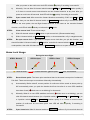
WKM Control Modes
GPS Atti. Mode
Atti. Mode
Manual Mode
Maximum angular velocity is 150°/s.
Command
Multi attitude control; Stick center position for
Stick Meaning
0˚ attitude, its endpoint is 35˚.
No attitude angle limitation and
vertical velocity locking.
Command
YES
Linearity
Lock rotor position
Only attitude
Stick Released
when GPS signal is
NOT Recommend
stabilizing.
adequate.
Maintain the altitude best above 1 meter from
Altitude Lock
NO
ground.
After 10s when GPS
Only performing
signal lost, system
attitude stabilizing
enters Atti. Mode
without position
automatically.
lock.
GPS Lost
---
Attitude & speed mixture control ensures
Safety
Depends on experience.
stability; Enhanced fail-safe
Applications
AP work
Sports flying.
---
3|
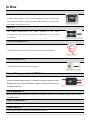
In Box
Main Controller (MC) ×1
The Main Controller (MC) is the brain of the system, it communicates with
the IMU, GPS/Compass,ESC and RC transmitter to carry out autopilot
functionality. The Main Controller provides USB interface to configure MC
and update firmware from a PC.
IMU ×1
The
Inertial
Measurement
Unit
(IMU)
consists
of
one
3-axis
accelerometer, one 3-axis gyroscope and a barometer. It is for sensing
the attitude.
GPS & Compass ×1
The GPS/Compass module is for sensing the position and direction.
LED Indicator ×1
The LED indicates different states of system.
Power Management Unit (PMU) ×1
Specially designed for WKM to solve the high power consumption
problem of power support system. It contains two power outputs for entire
WKM system and receiver separately, a battery voltage monitor, and two
CAN-Bus interfaces.
GPS Bracket ×1
Because the GPS & Compass are sensitive to magnetic interference, you should use this bracket to mount
the GPS module.
PMU Connecter ×1
For connections among Battery, ESCs and PMU.
USB Cable ×1
This cable is used to configure MC and update firmware.
4|
3-PIN Servo Cable ×10
Cables used to connect the Main Controller to the RC receiver.
3M Gummed Paper ×4
For fixing WKM components on multi-rotor’s frame.
Warranty Information Card ×1
It recommends the necessary conditions for using WKM system and related safety issues. Please fill out
the customer & multi rotor information card and return to DJI to register your product warranty.
5|
Contents
WARNING & DISCLAIMER.......................................................................................................................... 2
WKM PROFILE ............................................................................................................................................ 3
IN BOX ........................................................................................................................................................ 4
CONTENTS ................................................................................................................................................. 6
MATTERS NEED ATTENTION ..................................................................................................................... 7
ASSEMBLY ................................................................................................................................................. 8
ASSISTANT SOFTWARE ............................................................................................................................ 9
SOFTWARE AND DRIVER INSTALLATION.......................................................................................................... 9
GUI .......................................................................................................................................................... 9
FIRMWARE UPGRADE ................................................................................................................................. 11
PRODUCT INFO.......................................................................................................................................... 11
CONFIGURATION ......................................................................................................................................12
1.
MOUNTING.......................................................................................................................................12
2.
MOTOR MIXER .................................................................................................................................14
3.
TX MONITOR ....................................................................................................................................16
4.
AUTOPILOT ......................................................................................................................................21
5.
GIMBAL ...........................................................................................................................................28
6.
VOLTAGE MONITOR ..........................................................................................................................30
FLIGHT .......................................................................................................................................................34
DIGITAL COMPASS CALIBRATION .................................................................................................................34
TEST FLY .................................................................................................................................................36
FLY WITH GPS ..........................................................................................................................................38
APPENDIX..................................................................................................................................................39
CUSTOMIZE MOTOR MIXER .........................................................................................................................39
MULTI-ROTORS SUPPORTED.......................................................................................................................44
PORT DESCRIPTION ...................................................................................................................................45
LIGHT DESCRIPTION ..................................................................................................................................46
SPECIFICATIONS........................................................................................................................................47
6|
Matters Need Attention
For safety reasons, please pay serious attention to all following items:
1
Please disconnect ESCs and PMU Connecter or remove all propellers during configuration and
system setup!
2
Do not mount the IMU upside-down.
3
You have to reboot MC and redo the Tx calibration after you change RC system.
4
In Tx Calibration of assistant software:
5
Throttle: Slide left is craft down, slide right is craft up;
Rudder: Slide left is nose left, slide right is nose right;
Elevator: Slide left is craft back, slide right is craft front;
Aileron: Slide left is craft left, slide right is craft right.
GPS/Compass is sensitive to magnetic interference, should be far away from any electronic
devices.
6
Make sure switch on the transmitter first, then power on multi-rotor before takeoff! Power off
multi-rotor first, then switch off the transmitter after landing!
7
Do not fly in GPS Mode when the signal is not good (red light blinks)!
8
If you open the gimbal control in assistant software during the configuration, please note that
there is output from F1 and F2 ports. Now you should not connect these ports to ESCs which is
wired with propellers equipped motors.
9
Do NOT set the failed-safe position of throttle under 10% of endpoint.
10
Throttle stick position should always be higher than 10% from cut-throttle during the flight!
11
Low voltage protections are NOT fun! You should land your multi-rotor ASAP in any level of
protection to prevent your multi-rotor from crash or other harmful consequences!
12
By using Immediately mode to stop motors, in any control mode, once motors start and throttle
stick is over 10%, motors will stop immediately when throttle stick is back under 10% again. In
this case, if you push the throttle stick over 10% in 5 seconds after motors stop, motors will
re-start, Combination Stick Command (CSC) is no need. If you don’t push throttle stick after
motors start in three seconds, motors will stop automatically.
13
By using Intelligent mode to stop motors, motors will start or stop immediately when you
execute CSC. During normal flight, only pull throttle stick under 10% will not stop motors in any
control mode. You have to execute CSC to re-start motors if they stop during the flight.
14
When you set Mixer Type from Octo-rotor to Quad-rotor / Hexa rotor, the gimbal setting will
automatically switch to off for safety, which may lead the gimbal to tilt to one side, please turn
to the Gimbal section for reconfiguration.
7|
Assembly
·
·
IMU
R/C System
GPS/COMPASS
·
·
·
GPS/Compass is sensitive to magnetic interference, should be far away from any electronic devices.
You should use epoxy resin AB glue to assemble the GPS bracket first as the figure showed in previous page.
Mount the bracket on the center plate of craft first, then fix the GPS on the plate of the bracket (by 3M glue
provided). The GPS is sensitive to vibration interference, so position the bracket at least 10 cm from any rotor.
The DJI logo marked on the GPS should face the sky, with the orientation arrow pointing directly forward. The
GPS/Compass is packaged with a special indication line for mounting for the first time.
If you are uncertain whether materials near the GPS/Compass module are magnetic or not, you can use a
compass or magnet to check it. If you use your own mounting rod, make sure it is NOT magnetic!
·
These are example connections. Please
setup Aileron, Elevator, Throttle, Rudder
channels on your Tx first, and choose
one 2 or 3 positions switch/channel as
control mode switch, then connect your
receiver to the right ports on MC.
·
·
·
·
·
·
The IMU is best positioned near the multi rotor’s center of gravity, where
vibration is relatively low.
Orient the IMU such that the arrow marked on the printed surface of the
IMU faces the sky and points directly forward, backward, left or right.
The sides of the IMU should be precisely parallel to the multi rotor body.
Use double-sided foam tape for secured installation.
Check the double faced adhesive tape regularly to ensure that the IMU
is securely positioned.
DO NOT cover the ventilation holes, keep them unobstructed.
The IMU module is NOT water-proof or oil-proof.
Do not mount the IMU upside-down.
AUX2
R/C Receiver
(JR)
Main Controller
RUDD
ELEV
GEAR
AILE
AUX1
THRO
AUX2
·
1
·
2
R/C Receiver
(Futaba / Hitec)
3
4
ESC
M1-8
·
PMU & Battery
·
·
·
·
There is no requirement for
PMU mounting.
Use our PMU Connecter
(red line depicts in figure)
to connect battery, PMU
and ESCs.
For safety reason, please
disconnect ESCs and PMU
Connecter during the
configuration procedure.
You can choose 2S-6S
LiPo battery.
Battery
7
LED Indicator
·
·
Place the LED indicator a t a n appropriate
location of craft body far away from the GPS. Do
not mount it on other electronic devices.
Make sure You can see the light during the flight.
You can connect LED to the CAN-Bus port on
GPS connection wire.
After choosing a location to mount the MC, it is
recommended that you DO NOT mount the MC
until all wirings and software configurations are
completed.
F2
Futaba S-Bus
Roll
S-Bus
Pitch
F1
ESC & Motor
·
·
There is no orientation requirement for the Main
Controller. Choose a mounting location where
as shorter ESC extension wires are needed as
possible. Please make sure all ports are
accessible when installing the MC so as to
facilitate wiring and software configuration.
In three-pin ports, pins near the nicks are signal
pins.
·
·
·
·
Please make sure you are using the ESCs and motors recommended by the manufacturer of your multi rotor first. We
recommend you use DJI motors and ESCs. WKM output is 400Hz refresh frequency.
Connect all ESCs to MC by the motor numbering method introduced in our Assistant software.
If you use 3rd party ESCs, please make sure the ESCs travel midpoint is at 1520us. DO NOT use 700us travel
midpoint ESC, as it may lead aircraft to fly away or cause injury and damage. After connect ESCs, calibrate ESCs one
by one through the receiver directly before connect them to your MC, Make sure program all of them into Governor
off, Break off and Normal Start up to get best experience.
If you use 3rd party ESCs, please cut the red wire (power wire) of your ESCs , as the power from V-SEN on PMU is
suitable to most of receivers and other electronic devices.
If you use extra BEC, please use a servo cable without power wire to connect V-SEN to X1. (Not recommend)
8|
Assistant Software
Software and Driver Installation
STEP1:
Please download assistant software and driver from our website. If your operating system is
32bit, download 32bit driver; if your operating system is 64bit, download 64bit driver. Then
decompress;
STEP2:
Connect MC and PC via USB cable, power on MC;
STEP3:
If operating system tries to install driver automatically, cancel it.
STEP4:
Open folder DJI_Wookong_M_Driver_32bit or DJI_Wookong_Multi_Rotor_Driver_64bit,
double click Driver Setup.bat file and follow the steps to finish installation.
STEP5:
Open the assistant software folder, double click Setup.exe file and follow the steps to finish
installation.
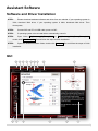
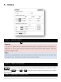
GUI
1
13 14
5
2
15
6
3
7
4
9
8
12
11
10
9|
1
TOOL
Firmware upgrade: Update your firmware from DJI server, keep your WKM system up-to-date.
Disable All Knob
Check for Updates: Check out the latest versions of assistant software and firmware. If necessary,
you can follow the links displayed to find the download page.
2
ABOUT
Info: Information regarding your WKM.
Error Code
3
中文: Chinese interface.
4
ENGLISH: English interface.
5
WRITE: Write data of the current page to your MC. The parameter or the title of which will turn red and
bold when modified, make sure you click the Write button or press Enter to update your system.
Optional parameters will be written to MC directly after modification.
6
READ: Read parameters from MC for current page.
7
EXPORT: Export configuration data.
8
IMPORT: Import version compatible configuration data.
9
Graphic guidance
10
Text guidance
11
CONTROL MODE: Control mode indication.
12
MC Output On: Indicates there are outputs to ESCs; when communication is built up between MC and
assistant software via USB cable, MC Output Off appears, it indicates no output to motors, then you
can configure your multi rotor with assistant software more safely!
13
Red light: WKMPC has been disconnected.
Green light: WKMPC has been connected.
Blue light: WKMPC communication.
14
Here you can find all the configuration contents in Configuration chapter.
15
Configuration step.
Notices:
Please power the MC first, then connect your MC to a internet enabled computer by the USB cable
before you open the assistant software. You have to register at the first time you use the assistant
software. It will auto detect software version when you open the assistant software and prompt
message if your version is not the latest one.
Do not disconnect MC and PC when your are importing or exporting data. You can only import
version compatible configuration data.
10 |
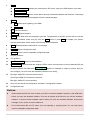
Firmware Upgrade
Please strictly follow the operation procedure for firmware upgrade, otherwise WKM might not work properly:
STEP1:
Make sure your computer is connected to the Internet.
STEP2:
Please close all the other applications during the firmware upgrade, including anti-virus
software and firewall.
STEP3:
Make sure the power supply is securely connected. DO NOT un-plug the power supply until
firmware upgrade has finished.
STEP4:
Connect MC to PC with Micro-USB cable, DO NOT break connection until firmware upgrade
is finished.
STEP5:
Run Software and wait for connection.
STEP6:
Select TOOLFirmware Upgrade.
STEP7:
DJI server will check your current firmware version, and get the latest firmware prepared for
the unit.
STEP8:
If there is a firmware version more up-to-date than your current version, you will be able to
click the Upgrade button.
STEP9:
Wait until Assistant software reads finished.
STEP10:
Click OK and power cycle the unit after at least 5 seconds.
Your unit is up-to-date now.
Notices:
After firmware upgrade, please re-configure WKM using Assistant software.
If it is notified that the network or DJI server is busy, please try again later with above procedures.
If firmware upgrade failed, WKM will enter waiting for firmware upgrade status automatically, please
try again with the above procedures.
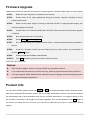
Product Info
You can check the MC product version via ABOUT Info. This includes software version, firmware version,
IMU version, hardware ID and loader version. S/N is a 32 digits authorization code for unit function activations.
We had already filled in the authorization code for your unit after manufacture. You might be asking to fill in
the new S/N in the future if you brought new function upgrades. Fill-in the S/N and then click Write button. If
you filled in an invalid S/N over 30 times, your MC will be locked and you have to contact our customer
support.
11 |
Configuration
1. Mounting
STEP1: IMU Orientation
Select IMU mounting orientation. Orient the IMU such that the arrow marked on the printed surface of the
IMU faces the sky and points directly forward, backward, left or right. The sides of the IMU should be
precisely parallel to the multi rotor body.
Notices:
Do not mount the IMU upside-down.
STEP2: Mounting Location
Install all payloads that will be used during the flight, including batteries, camera mount and camera. Balance
the multi rotor as you would normally, with the center of gravity (C.G.) directly on the center plate. Fill in the
distance between body center of IMU/GPS and the C.G. of multi rotor in X, Y & Z axles as showed in the
figure.
Notices:
12 |
1
You must re-configure if the ALL-UP-WEIGHT had been changed on your multi rotor,
2
If mounting locations are not accurate enough or the signs are wrong, error on X, Y,Z axles will leads
the oscillation of your multi rotor.
3
Make sure to follow the diagram in our assistant software: red is positive, green is negative; unit of
measure is CM, NOT INCH.
13 |
2. Motor Mixer
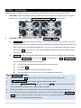
STEP1: Mixer Type
Set your transmitter into ACROBATIC mode. Then select the right mixer type according to your multi-rotor.
Tips:
We support nine types of multi-rotors. Please refer to “Multi-Rotors Supperted” in “Appendix”:
If you want to use gimbal with an Octo-rotor, you have to use S-Bus receiver, then you can use port
T and R for gimbal control. Otherwise, there will be no ports on MC for gimbal.
Notices:
Do NOT follow instruction from your multi-rotor manufacturer! Make sure the rotation direction of
each motor is the same as the way assistant software figure shows. If not, switch any of two wire
connetcions of the incorrect motor to change its rotation direction.
Make sure the type of propeller matches the rotation direction of motor.
When you set Mixer Type from Octo-rotor to Quad-rotor / Hexa rotor, the gimbal setting will
automatically switch to off for safety, which may lead the gimbal to tilt to one side, please turn to the
Gimbal section for reconfiguration.
Customize: This segment is reserved only for very special case, such as customized airframe in
non-conventional rotor arrangement. In the event, an airworthy multi-rotor craft with such rotor arrangement
will require customized setting to meet WKM controller algorithm. Please write to our support department or
dealer together with photos of the multi-rotor for assistance.
14 |
Tips:
Please refer to “Customize Motor Mixer” section in “Appendix” for how to customize a central
symmetry multi rotor.
If you customize the motor mixer of a quad-rotor or hexa-rotor, F1 and F2 ports can still be used for
gimbal servos control.
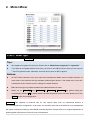
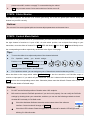
STEP2: Motor Idle Speed
Motor Idle Speed is the lowest speed after motor start. Set Motor Idle Speed will affect motor lowest speed
after motor start. There are five levels from LOW speed to HIGH speed, and the default is RECOMMEND.
You can click and drag cursor
to the corresponding level, to change Motor Idle Speed.
LOW
RECOMMEND
The lower motor idle speed
HIGH
The higher motor idle speed
Set Motor Idle Speed as LOW, the motor idle speed will be lowest.
Set Motor Idle Speed as HIGH, the motor idle speed will be highest.
RECOMMEND is the advised level.
You can reset the Motor Idle Speed according to the real situation.
Notices:
For user whose aircraft takes off at lowest throttles position, please set the idle speed at a low level.
For common users, please set Motor Idle Speed to RECOMMEND or above, since setting idle
speed too low may affect motor(s) spool up.
Tips:
The output pulse width for every grade of Motor Idle Speed is as followed
LOW
output pulse width
1144 us
RECOMMEND
1160 us
1176 us
HIGH
1192 us
1208 us
There is relationship between the output pulse width and the max/min pulse width when TX End
Point is 100%.
output pulse width=(max pulse-min pulse) x proportion + min pulse
You can get the proportion value by computing according to the above formula for a special TX. Use
Futaba TX for example. Notice that Futaba TX End Point is 100%.
LOW
RECOMMEND
HIGH
15 |
proportion value
3%
5
7%
9%
11%
3. Tx Monitor
Notices:
Make sure you have removed all propellers before this step!
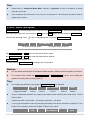
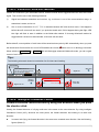
STEP1: Receiver Type
Choose the type of your receiver. If you use S-Bus receiver, please choose DJI’s S-Bus compatible option:
D-Bus. Otherwise choose Tradition.
Notices:
Please reboot MC and redo the calibration after you change the setup of your transmitter or change your
receiver!
Tips:
If you use S-Bus receiver, the communication of A, E, T, R, U, X2 and X3
channels are all through the D-Bus channel. Right figure shows the connection
of default transmitter channels and MC channels in S-Bus receiver (Only first 8
channels of S-Bus receiver are used at the moment). Then the original T and
Transmitter
Channels
1
2
3
4
5
6
7
MC
Channels
A
E
T
R
U
X2
X3
R channels are for Gimbal servo control.
16 |
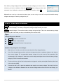
STEP2: Cut Off Type
Please read the introductions of start and stop motor in this step first, and then choose a cut off type.
1
Start Motor: When using WKM, pushing throttle stick before takeoff will not start motors. You have to
execute any one of following four Combination Stick Commands (CSC) to start motors:
2
Stop Motor: We provide two options to stop motors: Immediately, Intelligent.
Immediately Mode: By using this mode, in any control mode, once motors start and
throttle stick is over 10%, motors will stop immediately when throttle stick is back under 10%
again. In this case, if you push the throttle stick over 10% in 5 seconds after motors stop, motors
will re-start, CSC is no need. If you don’t push throttle stick after motors start in three seconds,
motors will stop automatically.
Intelligent Mode: By using this mode, different control mode has different way of stopping
motors. In Manual Mode, only executing CSC can stop motors. In Atti. or GPS Atti. Mode,
any one of following four cases will stop motors:
a)
You don’t push throttle stick after motors start in three seconds;
b)
Executing CSC;
c)
Throttle stick under 10%, and after landing 3 seconds.
d)
The slope angle of multi-rotor is over 70°, and throttle stick under 10%.
Tips (Intelligent Mode):
1
You have to execute CSC to start motors. Push throttle stick only will not start motors.
2
In Atti. / GPS Atti. Mode, it has landing judgment, which will stop motors.
3
Start motors in Atti. / GPS Atti. Mode, you have to execute CSC and then push throttle stick over
10% in 3 seconds, otherwise motors will stop after 3 seconds.
4
During normal flight, only pull throttle stick under 10% will not stop motors in any control mode.
5
For safety reason, when the slope angle of multi-rotor is over 70°during the flight in Atti. / GPS Atti.
Mode (may be caused by collision, motor and ESC error or propeller broken down), and throttle
stick is under 10%, motors will stop automatically.
17 |
6
You can stop motors by executing CSC in any control mode.
Notices:
1.
All these two cut off types will work properly only if Tx calibration is correct.
2.
When Tx commands are valid under any control modes, motors will start or stop immediately when
you execute CSC. It has nothing to do with current throttle stick position. Please DO NOT executes
CSC during flight without any reason.
3.
If you choose Immediately mode, you should not pull throttle stick under 10% during flight,
because that will stop motors. If you do it accidentally, you should push the throttle stick
over 10% in 5 seconds to re-start motors.
4.
If you choose Intelligent mode, throttle stick under 10% will trigger landing judgment in any control
mode. In this judgment, pitch, roll and yaw controls are denied except throttle, but multi-rotor will still
auto level.
5.
In any control mode, DO NOT pull throttle stick under 10% during normal flight without any reason.
6.
In any auto action caused by failed-safe or low voltage protection (e.g. auto Go Home)
,any
commands applied to start or stop motors are denied by MC, motors will hold state.
STEP3: Command Sticks Calibration
Slides Moving Definition:
T
: Slide left is craft down, slide right is craft up;
R
: Slide left is nose left, slide right is nose right;
E
: Slide left is craft back, slide right is craft front;
A
: Slide left is craft left, slide right is craft right.
STEP1:
Set endpoints of all channels to default values (100%) and set all trims and sub-trims of sticks
to 0 on your transmitter first. Keep all curves’ settings as default since the end-point of transmitter
sticks will be recorded here.
STEP2:
Click START button, and move all of the sticks throughout
their complete range several times.
STEP3:
After that, click FINISH button when you finished above procedures.
STEP4:
If the moving direction of the slide is opposite to the Slides Moving Definition, click the reverse
button REV/NORM beside.
Notices:
1.
All slides should become
when all the sticks are in the middle positions. If slides cannot go back
to center points (become ), just click FINISH, then slides will be at center automatically. If still not,
18 |
please reboot MC, and do not apply Tx command during the reboot.
2.
CSC may not start motors If trims and sub-trims of sticks are not 0!
STEP4: Sticks Monitor
This step is optional. X2 and X3 is for remote gain tuning; X3 is also for gimbal pitch control. Setup the
channel on your RC correctly.
Notices:
Do not use X3 to control gimbal pitch and remote adjust parameters at the same tiome.
STEP5: Control Mode Switch
Whichever 2 or 3 positions switch on your transmitter you have selected to use as control mode switch, wire
the right channel of receiver to U port of MC. At each switch position, use end-point fine tuning on your
transmitter, move the slider of channel U to GPS (GPS Atti Mode), A (Atti. Mode), M (Manual Mode) to turn
the corresponding area blue respectively as showed in the figure of last page.
Tips:
To move the slider is to adjust end-points of the channel selected.
For 3-position switch,
you should assign:
Position-1 to Manual Mode; Position-2 to Atti.
Mode; Position-3 to GPS Atti. Mode; or reverse
3 Position
Switch
1
2
3
Tx
the assignment for Position-1 and Position-3.
For 2-positions switch, you can assign any two of these three control modes as you like.
Move the slider to the range which reads Fail-Safe Mode to turn the area blue, set Fail-Safe output of
receiver to input port-U. If you switch off your transmitter now, the U channel slide should move to Fail-Safe
Mode and turn the corresponding area to blue. Otherwise please reset the fail-safe. Please refer to your RC
manual for the details of fail-safe setup.
Notices:
1.
Do NOT set the fail-safe position of throttle under 10% endpoint.
2.
MC would not execute Fail-Safe protection if you don’t set it properly. You can verify the Fail-Safe
settings by shutting down your transmitter, and then you can use the following methods to check
whether MC is already in Fail-Safe mode.
Check the Assistant Software status bar at the bottom side of the software
interface. Control mode will change to Fail-Safe.
Check the LED indicator. Read the appendix in this manual for details. LED will give blue
blinking if in fail-safe mode.
19 |
20 |
4. Autopilot
STEP1: Basic Parameters
Usually, the default parameters are ready to go. However, different multi rotors have different gains because
of different size, ESC, motor and propeller. If gain is too large, you will find the multi rotor oscillating in the
corresponding direction (About 5~10Hz). If too small, the multi rotor will likely to be hard to control. So you
can still setup the basic Gain of Pitch, Roll, Yaw and Vertical manually according to your multi rotor to have a
wonderful fly experience. We suggest you to change 10% to 15% of the parameter at a time.
To the gains of Pitch and Roll, if you release the Pitch or Roll stick after command stick, multi-rotor should be
back to hovering state. If the reaction of multi-rotor in this procedure is too soft (large delay), please increase
the basic gain slowly (10%-15% each time) until vibration emerges after you release the stick. Then decrease
the gain a little until vibration just disappears. Now the gain is perfect, but the reaction of the attitude change
is slow. You can follow the way introduced at the end of this section to tune the attitude gains.
The way of tuning the Yaw gain is the same as the way of adjusting the Tail Gyro. If you want fast stick
reaction speed, increase the gain, otherwise decrease the gain. However, the spin of multi-rotor is produced
by the counter torque force, and the magnitude of which is limited. Therefore, large gain will not produce tail
vibration like helicopter, but severe reaction at the start or stop of motors, which will affect the stabilization of
21 |
the other directions.
You use two methods to judge if the Vertical gain is good enough: 1) The multi-rotor can lock the altitude
when the throttle stick is at center position; 2) The change of altitude is small during the flight along a route.
You can increase the gain slowly (10% each time) until the vibration emerges along the vertical direction or
the reaction of throttle stick is too sensitive, then decrease 20% of the gain. Now it is a suitable Vertical gain.
Attitude gains determine the reaction speed of attitude from command stick, the bigger the value the quicker
the reaction. Increase it for sharper and quicker leveling action after command stick released. The control
feeling will be stiffness and rigid if the value is too high; and sluggish leveling action and slow braking if too
small.
Notices:
You must click Default button in first setup parameter, and subsequence firmware upgrade.
The vertical gain will NOT affect the manual mode.
Tips:
If you are a fresh player, you can tune the basic parameters first as following:
1
Increase the basic parameters 10% at a time so as to make your multi rotor hover or light
oscillate after small angular command input.
2
Decrease the basic parameters until your multi rotor can just hover, then decrease 10% more.
If the basic parameters are far away from the proper value, the advanced parameters will not work.
Here you can make use of remote gain-tuning channels to tune the gains during the flight:
1
Followed the instructions in “Assembly” R/C System section to connect and setup correctly;
2
Choose the X2 or X3 channel in Remote Adjust for the gain you want to tune. One channel to
one gain.
3
The range of remote tuning is from half current value to twice current value.
Usually the Pitch, Roll, Attitude Pitch and Attitude Roll Gains of hexa-rotor are higher than
quad-rotor.
STEP2: Advanced Parameters
Usually you can ignore this step. The default values are suitable for most of the conditions, so we do NOT
recommend you to change the parameters here. To some special multi rotor, experienced user can adjust the
advanced parameters to have a better fly experience.
22 |
STEP3: Enhanced Failed-Safe Methods
Choose one method for your failed-safe function, and the method will be triggered when MC loses the control
signal. This could be one of the following situations:
1)
Signal lost between transmitter and receiver, e.g. multi-rotor is out of the communication range, or
transmitter is down, and so on.
2)
One or more connections of A, E, T, R, U channels between MC and receiver loses. If this happens
before take-off, motors will not work if you push the throttle stick; if this happens during the flight, LED
blue light will flash to warn in addition to the failed-safe method. If Hovering failed-safe method is
triggered and U channel is disconnected, multi-rotor will auto land.
Before takeoff, current position of multi-rotor will be saved as home point by MC automatically when you push
the throttle stick first time after 6 or more GPS satellites are found (
blinks once or no blinking) 8 seconds.
When switch to Manual Mode or Atti. Mode, MC will disengage enhanced failed-safe mode, you can re-gain
control of multi rotor.
Tips:
The following schematic shown is introduction for Go-Home and Landing.
Home Location
If GPS satellite found >= 6 ,
at the first you pull the throttle stick,
then record Home Location
Ground
Multi rotor
1
Stay hover
Signal lost
Tx
Tx
2
3
Current location higher than 20m
Ready to
Go-Home
Go back first
20m
Signal lost > 3s
Tx
Hover 15s ,
Then land.
Current location lower than 20m
Tx
Tx
4
5
6
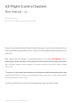
STEP4: Intelligent Orientation Control
Forward Direction: Multi-rotor will fly along this direction when you push
the elevator stick.
Usually, the forward direction of a flying multi-rotor is the same as the nose direction. By using Intelligent
Orientation Control (IOC), wherever the nose points, the forward direction has nothing to do with nose
direction:
In course lock flying, the forward direction is the same as a recorded nose direction. See the following
figures (Mode 2):
23 |
In course lock
Usually
In home lock flying, the forward direction is the same as the direction from home point to multi-rotor.
See the following figures (Mode 2):
Usually
In home lock
Home point
Home point
Before using this function, you have to choose a 2 or 3 positions switch on your transmitter as IOC switch.
Then wire the right channel of receiver to X2 port of MC. At each switch position, use end-point fine tuning on
your transmitter, move the slider of channel X2 to Home Lock, Course Lock, OFF to turn the corresponding
area blue respectively.
Tips:
1
3 Position
Switch
For 3-position switch:
2
3
Tx
Position-1 is OFF; Position-2 is Course Lock; Position-3 is Home Lock.
For 2-position switch:
Position -1 is OFF; Position-2 is Course Lock. Or Position -1 is OFF; Position-2 is Home Lock.
If you use S-Bus receiver, the default channel connection is shown in Tx Monitor – Receiver Type
section. Then you only need to assign a 2 or 3-position switch of your transmitter to the 5th channel.
Notices:
Do NOT set a 2-position switch as: Position-1 is Course Lock; Position-2 is Home Lock.
Course Lock Usage:
During the same flight:
STEP1: Record
STEP1:
a)
STEP2: Open
STEP3: Close
Nose direction;
Forward direction
STEP4: Re-open
Record forward direction: There are two ways: Manually; Automatically:
Automatically: MC will record the current nose direction as forward direction at 30th second
24 |
after you power on the multi-rotor. And LED will blink
b)
quickly if recording is successful.
Manually: You can slide X2 channel switch between OFF and Course Lock position quickly 3
to 5 times to record current nose direction as new forward direction at any time after you
power on multi-rotor 30 seconds. And LED will blink
STEP2:
quickly if recording is successful.
Open course lock: After record the forward direction successfully, if MC is in Atti. or GPS
Atti. mode, then you can slide X2 channel switch to Course Lock position to fly in course lock. Now
wherever the nose points, the real flight forward direction is the same as the recorded forward
direction, and LED will blink
STEP3:
slowly to indicate the IOC mode.
Close course lock: There are two ways:
a)
Slide X2 channel switch to OFF position to quit course lock; (Recommended way!)
b)
Slide U channel switch to Manual Mode position, or close transmitter, or fly in waypoint mode.
STEP4:
Re-open course lock: If you want to re-open course lock after you quit this function, you
should first slide X2 channel switch to OFF position, and slide U channel switch to Atti. or GPS Atti.
mode position, then slide X2 channel switch to Course Lock position to re-open course lock.
Home Lock Usage:
During the same flight:
STEP1: Record
Nose direction;
STEP1:
STEP2: Open
Forward direction;
STEP3: Close
Home point;
STEP4: Re-open
Over 10m distance
Record home point: The home point mentioned here is the same home point of enhanced
Fail-Safe. There are two ways to record here: Manually; Automatically:
a)
Automatically: Before takeoff, current position of multi-rotor will be saved as home point by
MC automatically when you push the throttle stick first time after 6 or more GPS satellites
have been found (
b)
blinks once or no blinking) for 8 seconds.
Manually: When 6 or more GPS satellites are found (
blinks once or no blinking), you can
slide X2 channel switch between (to a 3-position switch) Course Lock and Home Lock or (to
a 2-position switch) OFF and Home Lock position quickly 3 to 5 times to record current
position of multi-rotor as new home point. And LED will blink
quickly if recording is
successful.
STEP2:
Open home lock: Slide X2 channel switch to Home Lock position to fly in home lock when all
25 |
the following requirements are met:
a)
Home point is recorded successfully;
b)
6 or more GPS satellites are found;
c)
In GPS Atti. Mode;
d)
Multi-rotor is further than 10m away from home point.
Now wherever the nose points, the real flight forward direction is the same as the direction from
home point to multi-rotor, and LED will blink
STEP3:
slowly to indicate the IOC mode of MC.
Close home lock: There are three ways:
a)
Slide X2 channel switch to OFF position to quit home lock; (Recommended way!)
b)
Slide U channel switch to Manual Mode position, or close transmitter, or fly in waypoint mode.
c)
MC will be in course lock by current forward direction automatically when multi-rotor flies back
into 10m range around home point, or MC is in Atti. Mode.
STEP4:
Re-open home lock: If you want to re-open home lock after you quit this function, you should
first slide X2 channel switch to OFF position. When all 4 requirements in the 3rd step are met, slide
X2 channel switch to Home Lock position to re-open home lock.
Tips:
1
LED will blink
slowly to indicate the IOC mode only when MC is really fly in course lock or home
lock.
2
We suggest that you should know clearly that, by which lock method you are going to fly, and the
locked forward direction or home point, before you switch on IOC mode during the flight.
3
There is only one home point recorded at any time. This point is the same one used by Go-Home
and Landing fail-safe.
4
When flying by home lock, if GPS signal becomes weak, MC will be in course lock by current
forward direction automatically.
5
You’d better stand near the home point to use home lick.
6
You’d better use 3-position switch for X2 channel, and you’d better use X2 channel switch to open
and close IOC during the flight.
Notices:
1
Before home lock flight, you’d better fly the multi-rotor out of the 10m range around home point, then
slide X2 channel switch to Home Lock position to fly in home lock when all the requirements are
met. If you have already slide X2 channel switch to Home Lock position when the multi-rotor is still
in 10m range around home point, and this is the first time you are going to fly in home lock during
the current flight, then if all the requirements are met, MC will change into home lock automatically
when multi-rotor flies out the 10m range around home point.
26 |
2
When multi-rotor is flying by home lock far away from you and home point, please do not slide X2
channel switch many times quickly so as to avoid the change of home point without your attention.
3
By using a 3-position switch, if you want to record forward direction or home point manually, do not
slide X2 channel switch between OFF and Home Lock position, but only between OFF and Course
Lock, or Course Lock and Home Lock position. And please record the forward direction and home
point separately so as to make sure the recording is successful.
4
When you are flying in home lock, if the multi-rotor is back into the 10m range around home point, or
you switch into Atti. Mode, MC will fly in course lock by current forward direction automatically. But
this forward direction is NOT the recorded forward direction. If you open the course lock now, MC
will fly in course lock still by the recorded forward direction.
5
We suggest you to use home lock in a limited area which is 10m away from home point.
6
Continuously spinning will cumulate yaw error. LED will blink
to indicate huge cumulative yaw
error caused by spinning nose continuously in IOC. In this case, you can stop or slow down the
spinning, and continue flying after
blinking is off so as to have better flight performance.
27 |
5. Gimbal
STEP1: Gimbal Switch
If you use gimbal, please choose On here.
Notices:
If you open the gimbal control in assistant software during the configuration, please note that there is
output from F1 and F2 ports. Now you should not connect these ports to ESCs which is wired with
propellers equipped motors.
Tips:
If you want to use gimbal with an Octo-rotor, you have to use S-Bus receiver, then you can use port T and
R for gimbal control. Otherwise, there will be no ports on MC for gimbal.
STEP2: Servo Travel Limit
Range: -1000 to+1000.
MAX/MIN are servo travel limits; adjust them to avoid mechanical binding; Place your multi rotor on level
ground, adjust Center value of Pitch and Roll direction to make the camera mounting frame to your desired
angle-to-ground.
STEP3: Automatic Control Gain
28 |
Range: 0 to 100.
Adjust the reaction angle of automatic control. The initial value 100 is full angle. The bigger the gain, the
bigger the reaction angle. Click REV/NORM, and then you can reverse the feedback control directions.
STEP4: Manual Control Speed
Range: 0 to 100.
You should assign one of the knobs on your transmitter to X3 channel for controlling the Pitch direction (angle)
of camera gimbal during flight first. Then adjust the reaction speed of pitch direction manual control; the initial
value 100 is full speed.
Notices:
Do not use X3 to control gimbal pitch and remote adjust parameters at the same time.
29 |
6. Voltage Monitor
STEP1: Protection Switch
In order to prevent your multi-rotor from crash or other harmful consequences caused by low battery voltage,
we have designed two levels low voltage protections. You can choose to not to use them, however we
strongly recommend to open the protections here!
Notices:
Make sure two connections between PMU and MC (PW to CAN interface, V-SEN to X1) are correct,
otherwise the low voltage protection will not work properly.
All two level protections have LED warning as default. First level will blink yellow light
ceaselessly; second level will blink red light
ceaselessly.
All two level protections will only have LED warning under Manual Mode, no any automatic actions.
Low voltage protections are NOT fun! You should land your multi-rotor ASAP in any level of
protection to prevent your multi-rotor from crash or other harmful consequences!
STEP2: Battery
Power the MC by a battery and connect the MC with PC, current battery voltage will be displayed in this
column.
30 |
If the battery voltage displayed here is different from the voltage you measure from a
voltmeter, you have to calibrate. Click the Calibration, fill the voltage you have just
measured in the Calibration column of the dialogue box, and then click OK.
Meanwhile we need you to choose the battery type you are using, so that MC can provide default warning
voltages and ranges of warning voltages for you.
STEP3: First Level Protection
No Load (No Load Voltage): Self-defining warning voltage. Needs your input.
Loss (Line Loss Voltage): The battery voltage drop during the flight. Needs your input.
Loaded (Loaded Voltage): The real-time battery voltage during the flight. This is the actual warning voltage
monitored by MC. No needs your input, calculated by No Load and Loss.
Tips:
Voltages Magnitude Relation:
No Load: First level > Second level.
Loss: First level = Second level.
Loaded: Calculated, First level > Second level.
Method of Acquiring Line Loss Voltage:
1
Make sure you can fly your multi-rotor normally with a fully charged battery.
2
Use a fully charged battery, switch on the low voltage protections in assistant software, and observe
the current voltage. Fill a reasonable warning voltage in the No Load of first protection (We
recommend to fill a voltage 1V lower than current voltage and higher than minimum battery voltage
rating in). Fill 0V in Loss at the moment.
3
Fly the multi-rotor until the first level protection is triggered, and the yellow light is flashing. Now land
your multi-rotor ASAP.
4
Connect the MC to PC, open the assistant and acquire now current voltage. The Loss (Line loss
voltage) is the difference between the new current voltage and the first level No Load voltage you
filled in.
31 |
Notices:
If the line loss voltage of a battery is over 0.3V per cell (e.g. 3S battery over 0.9V), it’s because the
internal resistance of battery is high or the battery is too old, we suggest you to replace it!
Generally the line loss voltage of different battery is different. For the consideration of safety, you’d
better acquire all the line loss voltages of all your battery you are using, and fill the lowest one in the
Loss.
When you change the payload or multi-rotor, you have to get new line loss voltage.
The line loss voltage will be bigger after many times use, you should get new one after 30 times
charging.
Make sure your ESCs protection voltage is lower than 3.1V (1S), otherwise WKM low voltage
protection will not work.
1
Acquire the line loss voltage by the method introduced before first, and fill it in Loss.
2
Fill a reasonable warning voltage in the No Load.
3
Choose a safeguard: 1) LED warning: It is the default safeguard when you switch on the low voltage
protection; 2) Go Home and Landing: This safeguard will NOT be triggered when any of the following
items is satisfied:
a)
Manual or Atti. Mode;
b)
GPS signal is not good;
c)
The distance between Home Location and multi-rotor is smaller than 25m, and the altitude is
smaller than 20m relative to Home Location. Here the generation of Home Location is the same
as the way used in Enhanced Failed-safe. Please refer to Enhanced Failed-safe in “Autopilot”.
Notices:
There will be a 4 seconds LED warning before Go Home.
If you switch to Manual or Atti. Mode during Go Home, you will regain the control. LED warning will
be still on, please land ASAP.
If you switch back into the GPS Mode when you are in first level protection, you will have 15s time to
control your multi-rotor, you should land ASAP in this 15s to prevent your multi-rotor from crash or
other harmful consequences! After that if the Go Home and landing requirements are satisfied,
multi-rotor will Go Home and Landing automatically.
If you choose LED warning, please land ASAP after LED warning to prevent your multi-rotor from
crash or other harmful consequences!
Compare the Go Home and Landing of low voltage protection and the Go Home and Landing in
Enhanced Failed-safe, the generations of Home Location are the same; the Go Home routes are the
same; the difference is that there is no hovering before landing in low voltage protection.
32 |
STEP4: Second Level Protection
1
Fill the warning voltage and line loss voltage in No Load and Loss by the method introduced in previous
step.
2
When the second level protection is triggered, LED warning will be on. Meanwhile the center point of
throttle stick will move up slowly to 90% of endpoint, you should land ASAP to prevent your multi-rotor
from crash or other harmful consequences!
3
When the center point is at 90% of endpoint, multi-rotor will still ascend slowly if you continue to pull the
throttle stick, and the control of Pitch, Roll and Yaw are the same as before. Please land ASAP to
prevent your multi-rotor from crash or other harmful consequences!
Notices:
If your multi-rotor goes into the second level protection during Go Home in first level protection, it will land
immediately. If you switch into Manual or Atti. Mode, you will regain the control, and the center point of
throttle stick will move up slowly to 90% of endpoint. Please land ASAP to prevent your multi-rotor from
crash or other harmful consequences!
33 |
Flight
Digital Compass Calibration
Why calibrate the compass?
Ferromagnetic substances placed on multi rotor or around its working environment will affect the reading of
earth magnetic for digital compass, it also reduces the accuracy of the multi rotor control, or even reads
incorrect heading. Calibration will eliminate such influences, and ensure MC system performs well in a
non-ideal magnetic environment.
When to do it?
The first time you install WKM on your multi rotor.
When the multi rotor mechanical setup is changed:
a) If the GPS/Compass module is re-positioned.
b) If electronic devices are added/removed/ re-positioned (Main Controller, servos, batteries, etc).
c)
When the mechanical structure of the multi rotor is changed.
If the flight direction appears to be shifting (meaning the multi rotor doesn’t “fly straight”).
The LED indicator often indicates abnormality blinking when the multi rotor yaws. (It is normal for this to
happen only occasionally.)
Notices:
Don’t calibrate your compass where there is strong magnetic interference, such as magnetite, car
park, and steel reinforcement under the ground.
DO NOT carry ferromagnetic materials with you during calibration, such as keys or cell phones.
You don’t need to rotate your multi rotor on a precise horizontal or vertical surface, but keep at least
45°difference between horizontal and vertical calibration.
MC cannot work in the polar circle.
Calibration procedure
STEP1:
Enter calibration mode: quickly slide the control mode switch from Position-1 to Position-3 for
6 to 10 times, and LED indicator will be constantly on in blue;
STEP2:
Calibration in horizontal: rotate you multi rotor along with the horizontal surface until the green
light is on constantly, then go to the next step;
STEP3:
Calibration in vertical: while green light is constantly on, hold your multi rotor vertically and
34 |
rotate it along with its vertical axis, keep rotating until the green light is off, meaning the
calibration is finished.
STEP4:
After you finished the calibration, LED indicator will show whether the calibration was
successful or not:
If white light turns on for 3 seconds, calibration succeeds, calibration mode will auto exit;
If red light keeps blinking quickly, the calibration has failed. Slide the control mode switch one
time to cancel current calibration, and then re-start from step 1 for re-calibration.
Tips:
If you keep having calibration failure, it might suggest that there is very strong magnetic interference
around the GPS & Compass module, please avoid flying in this area.
35 |
Test Fly
Before First Flight
Notices:
Make sure you have assembled your multi rotor correctly.
Make sure you have done the configuration procedure correctly.
Any of the following mistakes will lead to dangerous accident, double check all these items:
Rotation direction of motor is opposite;
Propeller installation mistake;
IMU installation mistake;
Wrong connection between MC and ESC;
In Atti and GPS Atti mode, throttle stick center position is for 0m/s on the vertical direction. If you
pull the stick to the bottom during the flight, multi-rotor will descend; If you pull the stick to the bottom
on the ground, it will cut motors in 3 seconds. However the slow spinning of motors will affect the
flight performance, you’d better keep throttle stick position higher than 10% from cut-throttle during
the flight! In Manual Mode it will cut motors when pull throttle stick under 10%.
Make sure switch on the transmitter first, then power on multi-rotor! (Power off multi-rotor first, then
switch off the transmitter after landing!)
Please does the test fly and gain tuning with Atti. Mode in the open air without heavy wind! Please
read the first step of Autopilot in Configuration to learn how to tune gains.
Fly
STEP1:
Make sure your batteries are fully charged for your transmitter, MC and all the devices on your
multi rotor;
STEP2:
Check all connections and wirings, and make sure they are in good condition;
STEP3:
Switch on the transmitter first, then power on your multi-rotor!
STEP4:
Slide the control mode switch on your transmitter, and make sure it is working properly. Check
it with LED indicator to specify the current working mode for MC. See Appendix for details about
LED indicator;
STEP5:
Switch the system to Atti. Mode. Use any safe method to do the following test: Apply the
throttle to 20% slowly in 3 seconds after executing CSC and make sure all the motors are working,
and then try to push your sticks lightly in Roll, Pitch and Yaw to feel if your multi rotor moves to the
corresponding direction. If not, go back to Configuration Procedure correct your settings.
STEP6:
Push the throttle stick slowly in 3 seconds after executing CSC until all the rotors are working,
36 |
and then take-off your multi rotor gently.
Tips:
After a successful test fly, the preparation before taking off can be simplified: Put your multi rotor on the
plane ground, turn on the transmitter first, power on multi rotor, when the red light starts to blink normally,
you can take off in Atti. Mode.
37 |
Fly with GPS
Before Fly with GPS
Notices:
When system is powered on, you must not move your multi rotor or sticks on transmitter until the
system initialization is finished (about 5 second).
Make sure the GPS signal is good, without red LED blinking. Otherwise multi rotor will drift without
stick commands.
Please avoid using MC system in the following areas, where will GPS signal is most likely blocked:
Urban area with crowded buildings
Tunnels
Under bridges
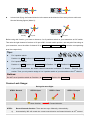
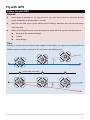
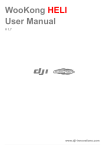
Tips:
Should you find the multi-rotor does not track straight in forward flight, you might try re-mounting GPS in an
offsetting angle as showed in right figure. Θ in the figure is the offsetting angle.
Actual fli
ion
ght direct
θ
Objective flight direction
GPS mounting direction
1
Without GPS offset angle
With GPS offset angle
2
3
θ
Actual flight direction
Objective flight direction
GPS mou
nting dire
ction
38 |
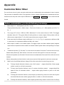
Appendix
Customize Motor Mixer
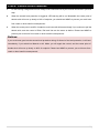
For a multi rotor, the roll, pitch, yaw and vertical axes are contributed by the combination of rotors’ outputs.
This procedure is called Mix Control. The proportion of rotors’ outputs is decided by the mechanical structure.
Customers can setup the motor output coefficients C in Motor Mixer Customize so as to realize the Mix
Control.
Before customization, you should following knowledge:
1.
Motor output = C × Stick position (A or E or T or R).
Torque produced by motor = Motor output × Force arm of motor (L) = C × Stick position (A or E or T or
R) × L
2.
The range of C is from -100% to 100%. Maximum C in the same column is 100%. The bigger
absolute value of C, The great effect of stick position on motor output. Stick position will not
affect motor output when C is 0, which means the motor output is fixed.
3.
Each motor has four different output coefficients: CT, CY, CP, CR. E.g. CY2 represents coefficient of M2
in yaw control; CR5 represents coefficient of M5 in roll control.
4.
Motor output is relative to its rotation speed. The bigger output, the faster rotation speed. Negative
output does not represent counter rotation, but slower rotation speed. Motor is still spinning if its output
is 0.
5.
Throttle stick position (T): Pull stick T<0, multi-rotor moves down; Push stuck T>0 multi-rotor moves up;
Rudder stick position (R): Stick left R<0, multi-rotor nose left; Stick right R>0, multi-rotor nose right;
Elevator stick position (E): Pull stick E<0 multi-rotor moves backward; Push stuck E>0, multi-rotor moves
forward;
Aileron stick position (A): Stick left A<0, multi-rotor moves left; Stick right A>0, multi-rotor moves right.
6.
Multi-rotor should keep balance along all the other axes when moves along one axis:
To keep throttle direction balance, sum of all motors’ output should be 0 when apply
rudder or pitch or roll stick command;
To keep yaw direction balance, sum of counter clockwise motors’ output should be
equal to sum of clockwise motors’ output when apply throttle or pitch or roll stick
command;
To keep pitch direction balance, total torques produced by motors at each side of pitch
axis should be the same when apply throttle or rudder or roll stick command;
To keep roll direction balance, total torques produced by motors at each side of roll axis
39 |
should be the same when apply throttle or rudder or pitch stick command。
7.
To pitch or roll control, proportion of coefficients of the motors at the same side of pitch or roll axis
should be equal to the proportion of force arms of those motors: Cm/Cn = Lm/Ln; Coefficient is 0%
if the force arm of that motor is 0.
M2
M2
M1
Roll Axis
M1
d
M6
M5
M6
Yaw Axis
a
M4
M3
M4
Pitch Axis
a
2d
M3
M1
M5
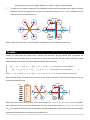
Now we take the Hexa-rotor V as an illustration to introduce how to customize motor mixer.
Throttle
Usually, we want push the throttle stick to ascend the multi-rotor; pull the throttle stick to descend the
multi-rotor; put the throttle stick at center point to hover the multi-rotor. We also want multi-rotor to keep
balance along all the other axes when apply the throttle stick command:
(𝐶𝑇1 +
(𝐶𝑇1
{
(𝐶𝑇2
+
𝐶𝑇3 + 𝐶𝑇5 ) × 𝑇 =
(𝐶𝑇2 + 𝐶𝑇4 + 𝐶𝑇6 ) × 𝑇 (To keep yaw direction balance)
+ 𝐶𝑇2 ) × 𝑇 × 𝑎 = (𝐶𝑇4 + 𝐶𝑇5 ) × 𝑇 × 𝑎 (To keep pitch direction balance)
𝐶𝑇4 + 2𝐶𝑇3 ) × 𝑇 × 𝑑 = (𝐶𝑇1 + 𝐶𝑇5 + 2𝐶𝑇6 ) × 𝑇 × 𝑑 (To keep roll direction balance)
1
As we defined before: Pull stick T<0, multi-rotor moves down; Push stuck T>0 multi-rotor moves up, we can
choose the following setup:
M2
M2
M1
Roll Axis
M1
d
M6
M5
Yaw Axis
M4
M6
a
M4
M3
Pitch Axis
a
2d
M3
M1
M5
Now if push the throttle stick, the sum of all motors output (CT1 + CT2 + CT3 + CT4 + CT5 +CT6)×T is positive,
then multi-rotor moves up; pull the throttle stick, the sum of all motors output (CT1 + CT2 + CT3 + CT4 + CT5
+CT6)×T is negative, then multi-rotor moves down. And the balance along all the other axes can be derived by
substituting the throttle stick command into equations set 1.
40 |
Yaw
The movement about yaw axis is produced by the counter torque force from the rotation of propeller. In our
example, M1 M3 M5 produce clockwise torque force; M2 M4 M6 produce counter clockwise torque force.
When the hexa-rotor is hovering, all the rotors are spinning at the same angular velocity, which means the
clockwise torque force equals to counter clockwise torque force, and this produces exactly 0 angular
acceleration about yaw axis. Therefore, when the rotate speed of M1 M3 M5 is larger than M2 M4 M6,
hexa-rotor spins clockwise; when the rotate speed of M1 M3 M5 is smaller than M2 M4 M6, hexa-rotor spins
counter clockwise. We also want multi-rotor to keep balance along all the other axes when apply the yaw stick
command:
(𝐶𝑅1 + 𝐶𝑅2 + 𝐶𝑅3 + 𝐶𝑅4 + 𝐶𝑅5 + 𝐶𝑅6 ) × 𝑅 = 0 (To keep throttle direction balance)
(𝐶𝑅1 + 𝐶𝑅2 ) × 𝑅 × 𝑎 = (𝐶𝑅4 + 𝐶𝑅5 ) × 𝑅 × 𝑎 (To keep pitch direction balance)
{
2
(𝐶𝑅2 + 𝐶𝑅4 + 2𝐶𝑅3 ) × 𝑅 × 𝑑 = (𝐶𝑅1 + 𝐶𝑅5 + 2𝐶𝑅6 ) × 𝑅 × 𝑑 (To keep roll direction balance)
As we defined before: Stick left R<0, multi-rotor nose left; Stick right R>0, multi-rotor nose right, we can
choose the following setup:
M2
M2
Roll Axis
M1
M1
d
M6
M5
Yaw Axis
M4
M6
a
M4
M3
Pitch Axis
a
2d
M3
M1
M5
Now if move the yaw stick right, the sum of M1, M3, M5 output (CR1 + CR3 + CR5) ×R is positive, the sum of M2,
M4, M6 output (CR2 + CR4 + CR6) ×R is negative, then the clockwise torque force is larger than counter
clockwise torque force, multi-rotor nose right; if move the yaw stick left, the sum of M1, M3, M5 output (CR1 +
CR3 + CR5) ×R is negative, the sum of M2, M4, M6 output (CR2 + CR4 + CR6) ×R is positive, then the clockwise
torque force is smaller than counter clockwise torque force, multi-rotor nose left. And the balance along all the
other axes can be derived by substituting the yaw stick command into equations set 2.
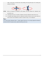
Pitch
The movement about the pitch axis is produced by the differential output of M1+M2 and M4+M5. Since M3
and M6 are on the pitch axis, they do not contribute and torque. You can just keep the rotation speed of M3
and M6 the same as hovering, so CP3 and CP6 are 0. Increase output of M4, M5 and decrease output of M1,
M2, multi-rotor moves forward; decrease output of M4, M5 and increase output of M1, M2, multi-rotor moves
41 |
backward. We also want multi-rotor to keep balance along all the other axes when apply the pitch stick
command:
(𝐶𝐸1 + 𝐶𝐸2 + 𝐶𝐸3 + 𝐶𝐸4 + 𝐶𝐸5 + 𝐶𝐸6 ) × 𝐸 = 0 (To keep throttle direction balance)
{ (𝐶𝐸1 + 𝐶𝐸3 + 𝐶𝐸5 ) × 𝐸 = (𝐶𝐸2 + 𝐶𝐸4 + 𝐶𝐸6 ) × 𝐸 (To keep yaw direction balance)
(𝐶𝐸2 + 𝐶𝐸4 + 2𝐶𝐸3 ) × 𝐸 × 𝑑 = (𝐶𝐸1 + 𝐶𝐸5 + 2𝐶𝐸6 ) × 𝐸 × 𝑑 (To keep roll direction balance)
3
Also proportion of coefficients of the motors at the same side of pitch axis should be equal to the proportion of
force arms of those motors: 𝐶𝐸1 ∶ 𝐶𝐸2 = 𝐶𝐸4 ∶ 𝐶𝐸5 = 𝑎: 𝑎 = 1: 1 . As we defined before: Pull stick E<0
multi-rotor moves backward; Push stuck E>0, multi-rotor moves forward, we can choose the following setup:
M2
M2
M1
Roll Axis
M1
d
M6
M5
Yaw Axis
M4
M6
a
M4
2d
M3
Pitch Axis
a
M3
M1
M5
Now if push the pitch stick, the sum of M1, M2 output (CE1 + CE2) ×E is negative, the sum of M4, M5 output
(CE4 + CE5) ×E is positive, then multi-rotor moves forward; if pull the pitch stick, the sum of M1, M2 output (CE1
+ CE2) ×E is positive, the sum of M4, M5 output (CE4 + CE5) ×E is negative, then multi-rotor moves backward.
And the balance along all the other axes can be derived by substituting the pitch stick command into
equations set 3.
Roll
The theory of movement about the roll axis is the same with pitch axis. However there is no motor on the axis
in this case, no coefficient is 0%. We also want multi-rotor to keep balance along all the other axes when
apply the roll stick command:
(𝐶𝐴1 + 𝐶𝐴2 + 𝐶𝐴3 + 𝐶𝐴4 + 𝐶𝐴5 + 𝐶𝐴6 ) × 𝐴 = 0 (To keep throttle direction balance)
{(𝐶𝐴1 + 𝐶𝐴3 + 𝐶𝐴5 ) × 𝐴 = (𝐶𝐴2 + 𝐶𝐴4 + 𝐶𝐴6 ) × 𝐴 (To keep yaw direction balance)
(𝐶𝐴1 + 𝐶𝐴2 ) × 𝐴 × 𝑎 = (𝐶𝐴4 + 𝐶𝐴5 ) × 𝐴 × 𝑎 (To keep pitch direction balance)
4
Also proportion of coefficients of the motors at the same side of roll axis should be equal to the proportion of
force arms of those motors: 𝐶𝐸2 ∶ 𝐶𝐸3 ∶ 𝐶𝐸4 = 𝐶𝐸1 ∶ 𝐶𝐸6 ∶ 𝐶𝐸5 = 𝑑: 2𝑑: 𝑑 = 1: 2: 1. As we defined before: Stick left
A<0, multi-rotor moves left; Stick right A>0 multi-rotor moves right, we can choose the following setup:
42 |
M2
M2
Roll Axis
M1
M1
d
M6
M5
Yaw Axis
M4
M6
a
M4
M3
Pitch Axis
a
2d
M3
M1
M5
Now if move the roll stick right, the sum of M2, M3, M4 output (CA2 + CA4 + 2CA3) ×A is positive, the sum of M1,
M5, M6 output (CA1 + CA5 + 2CA6) ×A is negative, then multi-rotor moves right; if move the roll stick left, the
sum of M2, M3, M4 output (CA2 + CA4 + 2CA3) ×A is negative, the sum of M1, M5, M6 output (CA1 + CA5 + 2CA6)
×A is positive, then multi-rotor moves left. And the balance along all the other axes can be derived by
substituting the roll stick command into equations set 4.
Summary
1.
Once you choose to customize, all coefficients are configurable. However, you only have to setup as
many as you need. Leave the rest 0%.
2.
Make sure you are clear about the definition of the positive and negative. Make sure you are also clear
about the relationship between the output quantity and motor rotation speed.
3.
Usually, the coefficients of throttle and yaw are 100% or -100%. The rest of the coefficients should be
decided by the proportion of force arms of the motors.
4.
The method introduced in this section is only suitable for central symmetry multi rotor.
43 |
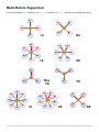
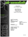
Multi-Rotors Supported
To coaxial propellers: Blue propeller is at Top; Red propeller is at Bottom. Otherwise all propellers are at top.
M1
M2
M2
M1
M3
M4
M4
+4
M3
X4
M1
M2
M2
M1
M6
M3
M1
M5
M3
M4
M4
+6
M1,4
M2,5
Rev
Y6
M3,6
M2
M8
M3
M5
X6
M2,5
M3,6
M1
M2
M6
M1,4
Y6
M1
M3
M8
M4
M7
M2,6
M1,5
M3,7
M4,8
M7
M4
M6
M5
+8
M5
M6
V8
X8
44 |
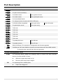
Port Description
Main Controller
A
For roll control (left/right)
E
For pitch control (front/back)
T
For throttle control
Or to gimbal roll servo
R
For rudder control
Or to gimbal pitch servo
U
For Control Mode Switch
X1
For voltage monitor (Connect with PMU V-SEN port)
X2
For D-Bus (S-Bus compatible)
Or for gain tuning
X3
For gimbal pitch control
Or for gain tuning
M6
To #6 rotor
M5
To #5 rotor
M4
To #4 rotor
M3
To #3 rotor
M2
To #2 rotor
M1
To #1 rotor
F2
To gimbal pitch servo
Or to #8 rotor
F1
To gimbal roll servo
Or to #7 rotor
Or for IOC switch
Micro-B USB port: PC connection for configuration and firmware upgrades.
CAN-Bus port: MC uses CAN-Bus to power and communicate with other WKM modules.
(In three-pin ports, pins near the nicks are signal pins.)
Power Management Unit
V-SEN
For monitoring battery voltage and supplying power to receiver and other electronic
devices. (Connect with MC X1 port)
PW
White wire (signal wire) output: ±3.3V
Red wire (power wire) output: 3A@5V
For supplying power to WKM system.
Output: Max [email protected]
45 |
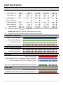
Light Description
Flight States
Manual Mode
Atti. Mode
GPS Atti. Mode
IOC
Tx Signal Lost
GPS satellites < 5
GPS satellites < 6
GPS satellites < 7
Attitude & GPS good
Attitude status fair
Attitude status bad
IMU data Lost
Sparking indications of
,
,
are: Single spark, all the sticks return to center, multi rotor hovering;
Double spark, stick(s) not at center, speed command is not zero.)
Fast blinking: Record forward direction or home point successfully.
Compass Calibration
Begin horizontal calibration
Begin vertical calibration
Calibration finished
Calibration or others error
Low Voltage Warning
First lever protection
Second lever protection
MC LED
MC is functioning well.
Boot loader mode, MC is waiting for firmware upgrading.
Firmware upgrading is finish. MC is waiting for reboot.
Error occurs during firmware upgrading, MC reboot is required.
or
PMU LED
PMU connection is correct.
Connection between PMU and battery is wrong (polarity error).
46 |
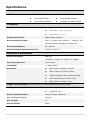
Specifications
General
Built-In Functions
Three Modes Autopilot
S-Bus Receiver Supported
Enhanced Fail Safe
2-axle Gimbal Support
Low Voltage Protection
Intelligent Orientation Control
Peripheral
Supported Multi-rotor
Quad-rotor: +4, X4;
Hexa-rotor: +6, X6, Y6, Rev Y6;
Octo-rotor: X8, +8, V8.
Supported ESC output
400Hz refresh frequency.
Recommended Transmitter
PCM or 2.4GHz with minimum 7 channels and
failed-safe function available on all channels.
Recommended Battery
2S ~ 6S LiPo
Assistant Software System Requirement
Windows XP SP3 / 7
Electrical & Mechanical
Power Consumption
MAX 5W
(0.9A@5V, [email protected], [email protected], 0.4A@8V)
Operating Temperature
-5°C to +60°C
Total Weight
<= 118g (overall)
Dimensions
MC: 51.2mm x 38.0mm x 15.3mm
IMU: 41.4mm x 31.1mm x 27.8mm
GPS & Compass: 50mm (diameter) x 9mm
LED Indicator: 25mm x 25mm x 7mm
PMU: 39.5mm×27.5mm×9.7mm
Flight Performance (can be effected by mechanical performance and payloads)
Hovering Accuracy (GPS Mode)
Vertical: ± 0.5m
Horizontal: ± 2m
Maximum Wind Resistance
<8m/s (17.9mph / 28.8km/h)
Max Yaw Angular Velocity
150deg/s
Max Tilt Angle
35°
Ascent / Descent
±6m/s
47 |
WooKong M
©2010-2011 Dajiang Innovation Technology Co. Ltd. All Rights Reserved.
6/F, HKUST SZ IER Building, No.9, Yuexing 1st Rd.,
South District, Hi-Tech Park, Shenzhen, 518057, Guangdong, China
Tel: +86-755-2665-6677
Sales ext: 201, 202, 203
Fax: +86-755-8306-7370
Service hotline: +86-755-2267-3777
Sales: [email protected]
Technical support: [email protected]
Others: [email protected]
DJI and WooKong is registered trademark of Dajiang Innovation Technology Co. Ltd. Names of product, brand, etc., appearing
in this manual are trademarks or registered trademarks of their respective owner companies. This product and manual are
copyrighted by Dajiang Innovation Technology Co. Ltd. with all rights reserved. No part of this product or manual shall be
reproduced in any form without the prior written consent or authorization of Dajiang Innovation Technology Co. Ltd. No patent
liability is assumed with respect to the use of the product or information contained herein.
48 |