1
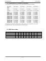
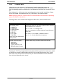
MSC CXC-PV525 Rev.1.3 User's Manual System Memory 2.5 The MSC CXC-PV525 CPU module provides two sockets for memory modules which have to meet the following demands: 204pin unbuffered DDR3 SO-DIMM 1.5V supply voltage DDR3-800 / PC3-6400 or faster Maximal module height: 30mm SPD (Serial Presence Detect) EEPROM Power Supply 2.6 +12V primary power supply input +5V standby Option, is not required for module operation. If not present, customer has to make sure that the supply voltages which are generated on the carrier board are switched off during suspend states, so that no current from the carrier board’s signal lines can flow to the CPU board. 3.3V RTC power supply Option, is not required for module operation. BIOS SETUP data is stored in a non volatile backup memory device (EEPROM), therefore configuration data will not get lost during power off (except for time and date information) Voltage +12V +5V Standby +3V RTC power supply 2.7 Input range +6.0V - 18.0 V +4.75V - 5.25 V +2.0V - 3.3V Current See next table max. 2A max. 6µA Current Dissipation All measurements were made by plugging a MSC CXC-PV525 module onto a MSC CXEVA2 Baseboard with a multimeter connected to the +12V Line. The module was equipped with two 1GByte memory modules. Three tests were performed: 1. Booting Dos 6.22 from an USB stick. 2. Booting Microsoft Windows XP Professional SP3 from an SATA harddrive to the desktop. 3. Booting Microsoft Windows XP Professional SP3 from an SATA harddrive and using BurnIn Test V4.0 to achieve 100% CPU load. Module (CPU) Intel® D525 Intel® D425 Intel® N455 DOS Prompt 0.86 A (10.3 W) 0.88 A (10.6 W) 0.73 A (8.8 W) Windows XP Idle 0.74 A (8.9 W) 0.77 A (9.2 W) 0.59 A (7.1 W) 11 / 61 100% CPU load 1.01 A (12.1 W) 0.90 A (10.8 W) 0.73 A (8.8 W)