1
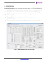
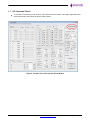
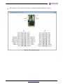
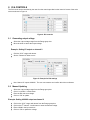
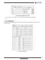
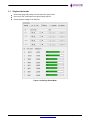
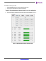
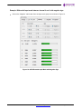
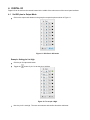
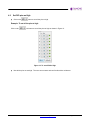
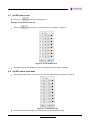
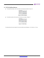
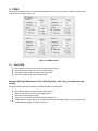
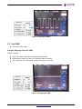
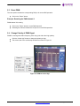
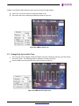
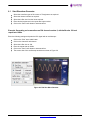
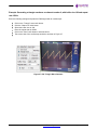
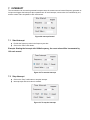
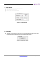
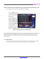
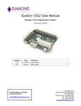
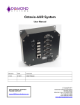
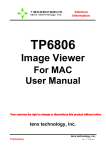
Graphical Control Panel User Manual
DS-MPE-DAQ0804
PCIe Minicard Data Acquisition Module
For Universal Driver Version 7.0.0 and later
Revision A.0
Revision
Date
A.0
3/18/2015
FOR TECHNICAL SUPPORT
PLEASE CONTACT:
[email protected]
March 2015
Comment
Initial release
Copyright 2015
Diamond Systems Corporation
555 Ellis Street
Mountain View, CA 94043 USA
Tel 1-650-810-2500
Fax 1-650-810-2525
www.diamondsystems.com
CONTENTS
1.
Introduction ....................................................................................................................................................... 3
1.1 I/O Connector Pinout ..................................................................................................................................... 4
2. D/A Controls ...................................................................................................................................................... 6
2.1 Generating output voltage ............................................................................................................................. 6
2.2 Manual Updating ........................................................................................................................................... 6
3. A/D Controls ...................................................................................................................................................... 7
3.1 Single ended mode ....................................................................................................................................... 8
3.2 Differential input mode .................................................................................................................................. 9
4. Digital I/O ......................................................................................................................................................... 11
4.1 Set DIO pins in output Mode ....................................................................................................................... 11
4.2 Set DIO pins as High ................................................................................................................................... 12
4.3 Set DIO pins as Low .................................................................................................................................... 13
4.4 Set DIO pins in input mode ......................................................................................................................... 13
4.5 DIO pull up/down resistor ............................................................................................................................ 14
5. PWM ................................................................................................................................................................. 15
5.1 Start PWM ................................................................................................................................................... 15
5.2 Stop PWM ................................................................................................................................................... 16
5.3 Reset PWM ................................................................................................................................................. 17
5.4 Change polarity of PWM signal ................................................................................................................... 17
5.5 Change duty cycle at run time ..................................................................................................................... 18
6. D/A Waveform generator ............................................................................................................................... 19
6.1 Start Waveform generator ........................................................................................................................... 20
7. Interrupt ........................................................................................................................................................... 22
7.1 Start Interrupt. ............................................................................................................................................. 22
7.2 Stop Interrupt ............................................................................................................................................... 22
7.3 Reset Interrupt ............................................................................................................................................. 23
8. Counter ............................................................................................................................................................ 23
8.1 Count-up mode ............................................................................................................................................ 24
8.2 Counter down mode .................................................................................................................................... 25
8.3 Reset Counter ............................................................................................................................................. 26
DS-MPE-DAQ0804 Control Panel Manual Rev A.0
www.diamondsystems.com
Page 2
1. INTRODUCTION
This document describes how to use the graphical control panel software for the DS-MPE-DAQ0804 PCIe
MiniCard analog I/O module.
Diamond Systems’ Universal Driver 7.0 must be installed before executing the GUI program. For more
details, read the Universal Driver installation instructions provided with the Universal Driver package.
To start the control panel software in windows double click the following executable file:
MPEDAQ0804_GUI.exe
To start the GUI in Linux, run the following executable file with root user permission:
$ ./MPEDAQ0804_GUI
The main window of the control panel software is displayed on the screen as shown below in Figure 1.
Figure 1: DS-MPE-DAQ0804 Control Panel Main Window
DS-MPE-DAQ0804 Control Panel Manual Rev A.0
www.diamondsystems.com
Page 3
1.1
I/O Connector Pinout
To view the I/O connector pin out, click the “I/O Connector Pinout” button in the upper right hand corner
of the main window, the location of which is shown below.
Figure 2: Location of the I/O Connector Pinout Button
DS-MPE-DAQ0804 Control Panel Manual Rev A.0
www.diamondsystems.com
Page 4
After clicking on “I/O Connector Pinout” button, a window is displayed as shown in Figure 3.
Figure 3: I/O Connector Pinout
DS-MPE-DAQ0804 Control Panel Manual Rev A.0
www.diamondsystems.com
Page 5
2. D/A CONTROLS
The D/A circuit can be controlled by the user from the controls provided on the lower left corner of the main
screen as shown in Figure 4.
Figure 4: D/A controls
2.1
Generating output voltage
Select the output voltage range from the Range group box.
Move the slider to select the output voltage.
Example: Setting 5V output on channel 0
Click the “0-5V” range radio button.
Set the “Channel 0” slider to max.
Figure 5: Example for D/A settings
Now “channel 0” outputs 4.9999V. The user can measure and confirm this with a multimeter.
2.2
Manual Updating
Select the output voltage range from the Range group box.
Click V on the DA / V radio button.
Enter the DA code as a voltage.
Click on “GO” to update.
Example: Setting 4.9998V output on channel 0
Click on the “0-5V” range radio button from the Range group box.
th
Click on the 0 channel V radio button to enter the manual voltage.
Enter 4.9998 in the input text box.
Click on “GO’ to update the voltage.
Figure 6: D/A Settings Manual Updating
Now “channel 0” has 4.9998V. The user can measure and confirm this with a multimeter.
3. A/D CONTROLS
The A/D circuit can be controlled by the user from the controls provided on the left side of the main screen as
shown in Figure 7.
Figure 7: A/D Controls
DS-MPE-DAQ0804 Control Panel Manual Rev A.0
www.diamondsystems.com
Page 7
3.1
Single ended mode
Choose the range and polarity from the respective group boxes.
Click on the “SE” radio button from Input mode group box.
Provide external voltage to the A/D pins.
Figure 8: A/D Single Ended Mode
DS-MPE-DAQ0804 Control Panel Manual Rev A.0
www.diamondsystems.com
Page 8
3.2
Differential input mode
Choose the Range and Polarity from the respective group boxes.
Click on the “DI” Radio button from Input mode group box.
Example: Differential input mode between channel 0 and 1 with positive sign.
Click on the “Positive” radio button from the Input mode group box as shown in Figure 9.
Figure 9: A/D Differential Input Mode with Positive Sign
DS-MPE-DAQ0804 Control Panel Manual Rev A.0
www.diamondsystems.com
Page 9
Example: Differential input mode between channel 0 and 1 with negative sign.
Click on the “Negative” radio button from the Input mode group box as shown in Figure 10.
Figure 10: A/D Differential Input Mode with Negative Sign
DS-MPE-DAQ0804 Control Panel Manual Rev A.0
www.diamondsystems.com
Page 10
4. DIGITAL I/O
Digital I/O can be set from the controls located in the middle of the main screen of the control panel software.
4.1
Set DIO pins in Output Mode
Click on the output radio buttons in the group box respective pins as shown in Figure 11.
Figure 11: DIO Pins in O/P mode
Example: Setting pin 0 to High
Click the pin 0 output radio button.
Toggle the
button of pin 0 to set the pin to high/low.
Figure 12: To set pin 0 High
Now the pin 0 is set high. The user can measure and confirm this with a multimeter.
4.2
Set DIO pins as High
Click on the
button to set all the pins to high.
Example: To set all the pins to high
Click on the
push button to set all the pins as high as shown in Figure 13.
Figure 13: To set all DIO’s High
Now all the pins are set high. The user can measure and confirm this with a multimeter.
DS-MPE-DAQ0804 Control Panel Manual Rev A.0
www.diamondsystems.com
Page 12
4.3
Set DIO pins as Low
Click on the
button to set all the pins low.
Example: To set all the pins to low
Click on the
push button to set all the pins to low as shown in Figure 14.
Figure 14: To set all DIO’s Low
Now all the pins are set low and the user can measure and confirm with a multimeter.
4.4
Set DIO pins in input mode
Click the Input radio button in the group box inside the respective ports as shown in Figure 15.
Figure 15: To set DIO as Input
Now all the pins are set to input mode and the user can provide external input.
DS-MPE-DAQ0804 Control Panel Manual Rev A.0
www.diamondsystems.com
Page 13
4.5
DIO Pull Up/Down Resistor
To set pull down resistor, click on the “Down” radio buttons as shown in Figure 16.
Figure 16: DIO Pull-Down
To set pull up resistor, click on the “Up” radio button as shown in Figure 17.
Figure 17: DIO Pull-Up
The resistor will pull to the set state if no input is provided to avoid floating— to 0 for down, to 1 for up.
DS-MPE-DAQ0804 Control Panel Manual Rev A.0
www.diamondsystems.com
Page 14
5. PWM
Pulse width modulators can be controlled and changed from the controls provided on the main screen of the
Control Panel as shown in Figure 18.
Figure 18: PWM Controls
5.1
Start PWM
Enter desired frequency value in the frequency input text box.
Enter desired duty cycle in the duty cyle input text box.
Select the Polarity as Active High or Low as required.
Click on the “Start” radio button to start PWM.
Example: Starting PWM Channel 0 with 100Hz frequency , 50% duty cycle and active high
polarity
Enter the following settings and probe the PWM signal with an oscilloscope:
Enter 100Hz frequency in the frequency input text box.
Enter 50% duty cycle in the duty cyle input text box.
Select the Polarity as Active High.
Click on the “Start” button to start the PWM on Channel 0.
A PWM signal of 100Hz, 50% duty cycle with high polarity will be generated. The screen shot of the
oscilloscope will appear as shown in Figure 19.
Figure 19: Starting the PWM
5.2
Stop PWM
Click on the “Stop” button
Example: Stopping Channel 0 PWM
PWM 0 is running.
Click on the “Stop” radio button to stop the channel 0 PWM.
PWM signal of 100Hz, 80% duty cycle with high polarity is stopped.
The screen shot of the oscilloscope would be as shown in Figure 20.
Figure 20: Stopping the PWM
DS-MPE-DAQ0804 Control Panel Manual Rev A.0
www.diamondsystems.com
Page 16
5.3
Reset PWM
The reset option releases the corresponding DIO pin for normal DIO operation.
Click on the “Reset” button.
Example: Resetting the PWM channel 0
PWM channel 0 is running.
Click on the “Reset” button to reset PWM channel 0.
Resetting the channel releases the I/O pins for normal DIO operations.
5.4
Change Polarity of PWM Signal
PWM 0 is running with 100Hz frequency, 80% duty cycle with active high polarity.
Click the “Active high” button to change the polarity to high.
The screen shot of the oscilloscope would be as shown in Figure 21.
Figure 21: PWM as Active High
DS-MPE-DAQ0804 Control Panel Manual Rev A.0
www.diamondsystems.com
Page 17
PWM 0 is running with 100Hz frequency, 80% duty cycle with active high polarity.
Click on the “Active low” button to change the polarity to low.
The screen shot of the oscilloscope would be as shown in Figure 22.
Figure 22: PWM as Active Low
5.5
Change Duty Cycle at Run Time
The duty cycle can be changed at while the PWM is running by selecting a new duty cycle and clicking
on the “Go” button. The PWM signal will be updated to new duty cycle value.
Here the PWM 0 is running with 50% duty cycle as shown in Figure 23.
Figure 23: PWM with 50% Duty Cycle
DS-MPE-DAQ0804 Control Panel Manual Rev A.0
www.diamondsystems.com
Page 18
To change the duty cycle value from 50 to 80%, enter value 80 in duty cycle input text box and click on
the “Go” button.
The screen shot of the oscilloscope would be as shown in Figure 24.
Figure 24: PWM with 80% Duty Cycle
6. D/A WAVEFORM GENERATOR
D/A waveforms can be generated from the settings located on the right hand side of the main screen of Control
Panel as shown in Figure 25.
Figure 25: D/A Waveform Generator
DS-MPE-DAQ0804 Control Panel Manual Rev A.0
www.diamondsystems.com
Page 19
6.1
Start Waveform Generator
Select the waveform type as Sine wave or Triangle wave as required.
Select the channel number as required.
Select the buffer size from the list as required.
Enter desired repeat rate in the repeat rate input text box.
Click on the “Start” radio button to start waveform.
Example: Generating a sine waveform on D/A channel number 0, with buffer size 128 and
repeat rate 100Hz.
Enter the following settings and probe the D/A signal with an oscilloscope:
Click on the “Sine” wave radio button.
Click on the channel 0 radio button.
Select the buffer size as 128.
Enter the repeat rate as 100Hz.
Click on the “Start” radio button to start waveform.
The screen shot of the oscilloscope would be as shown in Figure 26.
Figure 26: D/A Sine Wave Genrator
DS-MPE-DAQ0804 Control Panel Manual Rev A.0
www.diamondsystems.com
Page 20
Example: Generating a triangle waveform on channel number 0, with buffer size 128 and repeat
rate 100Hz.
Enter the following settings and probe the PWM signal with an oscilloscope:
Click on the “Triangle” wave radio button.
Click the “Channel 0” radio button.
Select the buffer size as 128.
Enter the repeat rate as 100Hz.
Click on the “Start” radio button to start waveform.
The screen shot of the oscilloscope would be as shown in Figure 27.
Figrue 27: D/A Triangle Wave Genrator
DS-MPE-DAQ0804 Control Panel Manual Rev A.0
www.diamondsystems.com
Page 21
7. INTERRUPT
The counter/timer can be used to generate interrupt events; the counter uses an internal frequency generator as
its input and triggers the interrupt at the requested rate. On each interrupt, counter value is incremented by one,
and the counter value is updated in GUI each second.
Figure 28: Interrupt Control
7.1
Start Interrupt.
Provide the frequency value in the frequency text box.
Click on the “Start” radio button.
Example: Starting the interrupt with 100Hz frequency, the count value will be incremented by
100 each second.
Figure 29: To start the Interrupt
7.2
Stop Interrupt
Click on the “Stop” radio button to stop the interrupt.
Interrupt stops and count value is retained.
Figure 30: To stop the Interrupt
7.3
Reset Interrupt
The reset option sets the count value back to zero.
Click on the “Reset” radio button.
Interrupt resets and count value resets.
Figure 31: To reset Interrrupt
8. COUNTER
The counter can be configured in either count-up or count-down mode. Click on the “Counter” button
located on the lower right hand corner of the main window as shown in Figure 32.
Figure 32: Counter/Timer control
DS-MPE-DAQ0804 Control Panel Manual Rev A.0
www.diamondsystems.com
Page 23
8.1
Count-up Mode
The counter can be configured in the up mode, and the count value will be incremented by one for each
falling edge clock source provided on the counter input pin.
To test this up mode easily, configure any one of the DIO pin in the output mode (E.g.: DIO0), then
connect the DIO pin to the counter input pin, when the user toggles the DIO pin (e.g.: DIO0) i.e. on each
falling edge the count value will be incremented by one.
Example: Starting the Counter 0 in up mode
Before clicking on the start button, the counter 0 input pin must be connected to any one of the DIO pin
(e.g.: DIO0) i.e DIO pin acts as clock source for the counter 0.
Click the Counter 0 Start radio button.
Toggle the DIO pin (e.g.: DIO0) in DIO section GUI and on each falling edge, the count value will be
incremented by one.
Figure 33: Incrementing the Counter
DS-MPE-DAQ0804 Control Panel Manual Rev A.0
www.diamondsystems.com
Page 24
8.2
Counter down mode
The counter can be configured in down mode using the internal 50MHz oscillator.
The user can configure frequency, output pulse polarity, and output pulse width in the down mode.
Example: Configure the counter 0 with 100Hz frequency, low polarity and pulse with as 1 clock
Click on the “Start” button and the oscilloscope image displayed will be similar to the one shown in
Figure 34:
Figure 34: Decrementing the Counter (Low Polarity)
DS-MPE-DAQ0804 Control Panel Manual Rev A.0
www.diamondsystems.com
Page 25
Example: Configure counter 0 with 100Hz frequency, high polarity and pulse width as 1 clock
Click the “Start” button and the oscilloscope image below is displayed.
Figure 34: Decrementing the Counter (High Polarity)
Another example of how to demonstrate the function of the counter/timers on the board is to connect the output
pin of one counter/timer to the input pin of another, and set one to count down, and the other to count up.
Clicking “Start” on both counter/timers will allow the user to see the second counter increment at the rate
defined by the first.
8.3
Reset Counter
The stop option in the GUI does not release the counter pin for normal DIO operation, hence to reset
the counter and release the DIO pin for normal DIO operation, click on the “Reset” button.
DS-MPE-DAQ0804 Control Panel Manual Rev A.0
www.diamondsystems.com
Page 26