1
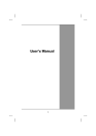
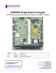
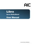
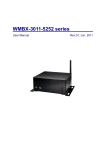
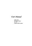
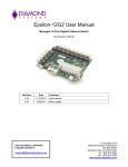
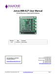
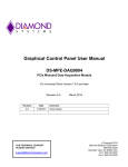
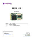
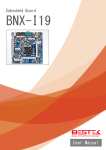
Octavio-AUR System
User Manual
Revision
Date
Comment
v1.00
6/15/11
Initial Release
FOR TECHNICAL SUPPORT
PLEASE CONTACT:
[email protected]
Copyright 2011
Diamond Systems Corporation
555 Ellis Street
Mountain View, CA 94043 USA
Tel 1-650-810-2500
Fax 1-650-810-2525
www.diamondsystems.com
TABLE OF CONTENTS
1
2
3
4
5
6
7
Introduction ....................................................................................................................................................... 5
1.1
Functional Specifications ................................................................................................................................ 5
1.2
Physical Specifications ................................................................................................................................... 5
1.3
Available Options ............................................................................................................................................ 6
Functional Overview......................................................................................................................................... 7
2.2
Octavio-AUR Functional Block Diagram ........................................................................................................ 8
2.3
Aurora SBC Functional Block Diagram .......................................................................................................... 9
2.4
External Connector Summary ...................................................................................................................... 10
Getting Started ................................................................................................................................................ 12
3.1
System Setup ............................................................................................................................................... 12
External Connectors....................................................................................................................................... 13
4.1
Serial Ports 1, 2, 3, 4 .................................................................................................................................... 13
4.2
Keyboard, Mouse ......................................................................................................................................... 14
4.3
USB1, USB2, USB3, USB4 .......................................................................................................................... 14
4.4
Power In ....................................................................................................................................................... 15
4.5
VGA .............................................................................................................................................................. 15
4.6
Ethernet ........................................................................................................................................................ 16
Internal Configuration Jumpers .................................................................................................................... 17
5.1
Jumper Summary ......................................................................................................................................... 17
5.2
RS-232 / RS-422 / RS-485 Configuration (JCOM3, JCOM4) ...................................................................... 17
End Cap Dimensions ...................................................................................................................................... 18
Technical Support .......................................................................................................................................... 18
Octavio-AUR User Manual
www.diamondsystems.com
Page 2
IMPORTANT SAFE HANDLING INFORMATION
WARNING!
ESD-Sensitive Electronic Equipment
Observe ESD-safe handling procedures when working with this product.
Always use this product in a properly grounded work area and wear
appropriate ESD-preventive clothing and/or accessories.
Always store this product in ESD-protective packaging when not in use.
Safe Handling Precautions
The Octavio unit contains a high number of I/O connectors with connection to sensitive electronic components. This
creates many opportunities for accidental damage during handling, installation and connection to other equipment.
The list here describes common causes of failure found on boards returned to Diamond Systems for repair. This
information is provided as a source of advice to help you prevent damaging your Diamond (or any vendor’s)
embedded computer boards.
ESD damage – This type of damage is usually almost impossible to detect, because there is no visual sign of
failure or damage. The symptom is that the board eventually simply stops working, because some component
becomes defective. Usually the failure can be identified and the chip can be replaced.
To prevent ESD damage, always follow proper ESD-prevention practices when handling computer boards.
Damage during handling or storage – On some boards we have noticed physical damage from mishandling. A
common observation is that a screwdriver slipped while installing the board, causing a gouge in the PCB surface
and cutting signal traces or damaging components.
Another common observation is damaged board corners, indicating the board was dropped. This may or may not
cause damage to the circuitry, depending on what is near the corner. Most of our boards are designed with at least
25 mils clearance between the board edge and any component pad, and ground / power planes are at least 20 mils
from the edge to avoid possible shorting from this type of damage. However these design rules are not sufficient to
prevent damage in all situations.
A third cause of failure is when a metal screwdriver tip slips, or a screw drops onto the board while it is powered on,
causing a short between a power pin and a signal pin on a component. This can cause overvoltage / power supply
problems described below. To avoid this type of failure, only perform assembly operations when the system is
powered off.
Power supply wired backwards – Our power supplies and boards are not designed to withstand a reverse power
supply connection. This will destroy each IC that is connected to the power supply (i.e. almost all ICs). In this case,
the board will most likely cannot be repaired and must be replaced. A chip destroyed by reverse power or by
excessive power will often have a visible hole on the top or show some deformation on the top surface due to
vaporization inside the package. Check twice before applying power!
Board not installed properly in PC/104 stack – A common error is to install a PC/104 board accidentally shifted by 1
row or 1 column. If the board is installed incorrectly, it is possible for power and ground signals on the bus to make
contact with the wrong pins on the board, which can damage the board. For example, this can damage components
attached to the data bus, because it puts the 12V power supply lines directly on data bus lines.
Overvoltage on analog input – If a voltage applied to an analog input exceeds the design specification of the board,
the input multiplexor and/or parts behind it can be damaged. Most of our boards will withstand an erroneous
connection of up to 35V on the analog inputs, even when the board is powered off, but not all boards, and not in
all conditions.
Octavio-AUR User Manual
www.diamondsystems.com
Page 3
Overvoltage on analog output – If an analog output is accidentally connected to another output signal or a power
supply voltage, the output can be damaged. On most of our boards, a short circuit to ground on an analog output
will not cause trouble.
Overvoltage on digital I/O line – If a digital I/O signal is connected to a voltage above the maximum specified
voltage, the digital circuitry can be damaged. On most of our boards the acceptable range of voltages connected to
digital I/O signals is 0-5V, and they can withstand about 0.5V beyond that (-0.5 to 5.5V) before being damaged.
However logic signals at 12V and even 24V are common, and if one of these is connected to a 5V logic chip, the
chip will be damaged, and the damage could even extend past that chip to others in the circuit.
Bent connector pins – This type of problem is often only a cosmetic issue and is easily fixed by bending the pins
back to their proper shape one at a time with needle-nose pliers. The most common cause of bent connector pins is
when a PC/104 board is pulled off the stack by rocking it back and forth left to right, from one end of the connector
to the other. As the board is rocked back and forth it pulls out suddenly, and the pins at the end get bent
significantly. The same situation can occur when pulling a ribbon cable off of a pin header. If the pins are bent too
severely, bending them back can cause them to weaken unacceptably or even break, and the connector must be
replaced.
Octavio-AUR User Manual
www.diamondsystems.com
Page 4
1 INTRODUCTION
Octavio-AUR embedded application servers are compact, rugged systems aimed at a wide variety of data
gathering and control applications. The systems are based Diamond’s field-proven Aurora PC/104 single board
computer, which combines a 1.6GHz Intel Atom Z530 CPU and integrated peripheral interface functions.
TM
Octavio-AUR comes with either a 1GB or 2GB rugged RSODIMM module for increased resistance to shock and
vibration. It also has a 4GB solid state USB flashdisk pre-loaded with Linux 2.6.23, leaving ample room for your
application on the flashdisk.
Standard system I/O includes VGA graphics, a Gigabit Ethernet interface, four USB 2.0 ports, two RS-232 serial
ports, two RS-232/422/485 ports, and PS/2 keyboard and mouse interfaces.
The Octavio-AUR enclosure is designed to eliminate most internal cables, resulting in enhanced ruggedness and
reliability in both fixed and mobile environments.
All of the system’s standard interfaces are accessible on the front of the enclosure via industry standard
connectors, which are mounted on a Panel I/O Board. The system is highly shock and vibration tolerant, and can
operate fanless over -40°C to +85°C.
1.1
Functional Specifications
1.1.1
System Core Functions
Based on Diamond Systems’ Aurora single-board computer (SBC)
o Processor: 1.6GHz Intel Atom Z530P CPU
TM
o System Memory: 1GB or 2GB ruggedized RSODIMM
Display type: VGA CRT; up to 1280 x 1024 resolution
USB ports: four USB 2.0
Serial ports: two RS-232/422/485; two RS-232-only
Networking: Gigabit Ethernet
Mass storage: integrated 4GB USB flashdisk
Keyboard/mouse: PS/2 or USB
Operating system: Linux 2.6.23
1.2
Physical Specifications
1.2.1
Power
Input power: 5VDC ±5%
Power Consumption: 5.4W typical
1.2.2
Mechanical
Footprint: 5.75 x 5.50 inches (145 x 138mm)
Case heights: 1.7 inches (43 mm)
Weight: 31 oz (864 g)
1.2.3
Environmental
FCC Class B: available on request
UL: CUL available on request
CE Mark: available on request
RoHS: compliant
Octavio-AUR User Manual
www.diamondsystems.com
Page 5
1.2.4
Thermal
Operating temperature: -40°C to +85°C
Storage temperature: -40°C to +85°C
1.3
Available Options
Octavio-AUR systems come in standard, default configurations for various system aspects such as serial port
configuration. Some of these may be configured to your specifications during manufacturing. The table below
indicates the options that are available as standard product. For further details on how to order an Octavio-AUR
system with a selection of these options, please refer to the Octavio Ordering Guide, available for download from
the Diamond Systems website.
Option
Aurora SBC model
Description
Based on 1.6GHz Atom Z530 CPU; includes 1GB ruggedized RSODIMMTM
Based on 1.6GHz Atom Z530 CPU; includes 2GB ruggedized RSODIMMTM
Flashdisk
4GB USB flashdisk, pre-loaded with Linux 2.6.23
Case height
1.7 inches
DIN Rail Adapter
No DIN rail adapter kit
With DIN rail adapter kit
Serial Ports 3 and 4
data protocol
RS-232 (default)
RS-422
RS-485
Console Redirection
Off (default)
On (user definable)
1.3.1
Additional Customization
Additional customizations can be accommodated. Following are some examples:
Substitute Windows CE for Linux operating system
Contact Diamond Systems for details on these and other customization options.
Octavio-AUR User Manual
www.diamondsystems.com
Page 6
2 FUNCTIONAL OVERVIEW
The key physical components of an Octavio-AUR system are illustrated in the figure below.
Aurora SBC
2.1.1
Aurora SBC
The Aurora single board computer (SBC) implements Octavio-AUR’s core embedded computing and system
interface functions. The SBC provides a conduction cooling thermal solutions that mates to the Octavio end cap
and transfers the heat efficiently out of the enclosure.
2.1.2
Panel I/O Board
Nearly all of the I/O interface signals present on Octavio-AUR’s external interface connectors originate from
functions on the Aurora SBC. The Panel I/O Board serves as a transition adapter between male header connectors
on the top of the Aurora SBC and industry-standard interface connectors accessible from the top of the OctavioAUR.
The Panel I/O Board also provides an SDVO to VGA conversion circuit to provide standard VGA display output
from the system.
2.1.3
DC Power Input
The Power Control circuitry on the Panel I/O Board supports one source of DC power input:
A +5VDC ±5%
Octavio-AUR User Manual
www.diamondsystems.com
Page 7
2.2
Octavio-AUR Functional Block Diagram
The block diagram below illustrates the functional subsystems contained in the Octavio-AUR system. These
subsystems are briefly described thereafter.
Octavio-AUR User Manual
www.diamondsystems.com
Page 8
2.3
Aurora SBC Functional Block Diagram
The Aurora SBC’s block diagram appears below.
For more information about the Aurora SBC, refer to the Aurora User Manual (PDF file link), which can be
downloaded from the Diamond Systems’ website’s Aurora SBC webpage at
(http://www.diamondsystems.com/aurora).
Octavio-AUR User Manual
www.diamondsystems.com
Page 9
2.4
External Connector Summary
The figure below illustrates Octavio’s front panel I/O interface connectors. These connectors, which are mounted on
the top side of the Panel I/O Board, provide basic computer functions such as keyboard, mouse, VGA, Ethernet,
and USB. The table on the following page summarizes the utilization of each connector. For details regarding the
functions and signal assignment of each external connector, refer to Section 4 of this document.
Octavio-AUR User Manual
www.diamondsystems.com
Page 10
Label on Enclosure
Connector Type
Function
COM1, COM2
DB9 male
Serial port RS-232 only
COM3, COM4
DB9 male
Serial port. Default RS-232, can be configured as
RS-232, RS-422, or RS-485
USB1-USB4
USB Type A
Universal Serial Bus
ETHERNET
RJ45
Ethernet port
VGA
DD15 female
Video port
KEYBOARD
Mini-DIN female
Interface to PS/2 keyboard
MOUSE
Mini-DIN female
Interface to PS/2 mouse
POWER IN
Molex 39-30-2045 or
equivalent
Input power. +5VDC
Octavio-AUR User Manual
www.diamondsystems.com
Page 11
3 GETTING STARTED
The Octavio-AUR is shipped fully assembled. Following are instructions to start using the Octavio-AUR system.
WARNING!
Be sure to observe the ESD precautions listed on page 3 of this manual.
3.1
System Setup
3.1.1
Display
Octavio-AUR can be used with standard VGA-interfaced CRT or LCD monitors. Plug the monitor’s VGA interface
cable into the system’s external VGA connector.
3.1.2
Keyboard and Mouse
Octavio-AUR supports operation using either PS/2- or USB-interfaced keyboard and mouse devices, in any
combination. Connect these peripheral devices as follows:
Connect the cable from a PS/2 keyboard to the external connector labeled KEYBOARD
Connect the cable from a PS/2 mouse to the external connector labeled MOUSE
Connect the cables from a USB keyboard or USB mouse to any of the system’s USB ports (USB1, USB2,
USB3, or USB4)
3.1.3 Input Power
Connect an external source of +5V ±5% DC power to pin 4 of the POWER IN connector, and GROUND to either (or
both) pins 2 or 3. Refer to the figure below for the connector’s pin numbering.
4
1
3.1.4 System Boot
Turn on the DC power supply. The unit will display startup messages, and then boot to a Linux prompt.
3.1.5 Linux Operating system
Octavio-AUR contains an USB flashdisk attached to the Aurora SBC. This solid-state disk device by default
contains a bootable Linux OS, which provides a quick-boot compact Linux environment based on combination of
Slackware 2.6.23 kernel with BusyBox tools. The Linux OS utilizes the EXT3 file system, and grub bootloader for a
quick boot.
For more information regarding Octavio-AUR’s embedded Linux operating system, refer to the Linux SDK
description on the Diamond Systems website.
3.1.6
Console Redirection Option
Octavio-AUR provides the ability to utilize a serially-interfaced computer other device as the system console,
instead of (or in addition to) using the normal VGA CRT display and PS/2 or USB keyboard. Octavio-AUR by
default comes with serial console redirection turned off. If desired, the user can enable console redirection as
follows.
In the advanced menu, the user can select any of the serial ports for console redirection with different speeds
ranging from 115200bps to 9600bps as follows.
Advanced - Remote Access Configuration - Disabled (Default)
Octavio-AUR User Manual
www.diamondsystems.com
Page 12
When set to Enabled, the console re-direction is activated on COM1 by default at 115200,n,8,1 communication
settings. The remote access configuration can be enabled on any of the four COM ports. Baud rates supported
are 115200 (default when enabled), 57600, 38400, 19200 and 9600.
4 EXTERNAL CONNECTORS
This section describes Octavio’s external interface connectors. These are intended for direct connection via
standard external peripheral interface cables for devices such as a PS/2 keyboard and mouse, VGA monitor, and
various serial devices. The external connectors discussed in this section are affixed to the top side of the Panel I/O
Board. These connectors’ signals come from another set of connectors located on the bottom side of the Panel I/O
Connector. The latter set of connectors is discussed in detail in the next section, “Error! Reference source not
found..”
4.1
Serial Ports 1, 2, 3, 4
These four serial port connectors, labeled on the outside of the enclosure as COM1, COM2, COM3 and COM4, are
male DB9 connectors. They connect via the Panel I/O Board to the Aurora SBC.
Depending on the preassembled setup of the Octavio-AUR systems, serial ports can be either standard or
configured at the time of order.
In a standard Octavio-AUR system, COM1-4 only support RS-232 protocols.
The Octavio-AUR can be ordered with COM3 and COM4 configured to support RS-422, or RS-485
protocols. (COM1 and COM2 are limited to RS-232 only.)
RS-232 Configuration
RS-422 Configuration
Signal
Name
DCD 1
DB9
Pin
1
6
Signal
Name
DSR 1
Signal
Name
NC
RXD 1
2
7
RTS 1
TXD 1
3
8
CTS 1
DTR 1
4
9
RI 1
GND
5
Octavio-AUR User Manual
DB9
Pin
1
6
Signal
Name
NC
TXD+ 1
2
7
TXD- 1
GND
3
8
RXD- 1
RXD+ 1
4
9
NC
GND
5
www.diamondsystems.com
RS-485 Configuration
Signal
Name
NC
TXD/RXD
+1
GND
DB9
Pin
1
6
3
8
Signal
Name
NC
TXD/RXD
-1
NC
NC
4
9
NC
GND
5
2
7
Page 13
4.2
Keyboard, Mouse
These two 6-pin female Mini-DIN connectors provide interfaces for USB Keyboard and Mouse devices. The signals
connect via the Panel I/O Board to the Aurora SBC.
KEYBOARD/MOUSE — Mini-DIN Connector
4.3
1
Data
2
Reserved
3
System Ground
4
System Power (5V)
5
Data Clock
6
Reserved
USB1, USB2, USB3, USB4
These four connectors are industry standard Type A USB connectors. The signals connect via the Panel I/O Board
to the Aurora SBC.
USB1, USB2, USB3, USB4 -- Type A USB connector
Octavio-AUR User Manual
1
System Power (5V)
2
Data Positive
3
Data Negative
4
System Ground
www.diamondsystems.com
Page 14
4.4
Power In
Input power is supplied as +5VDC as show below.
POWER IN — Power Input Connector
4.5
1
NC
2
System Ground
3
System Ground
4
+5V In
VGA
The VGA connector is a traditional, industry standard female DB15 connector, which is numbered (viewed from the
outside) as shown below:
Octavio-AUR User Manual
1
Red Video
2
Green Video
3
Blue Video
4
Reserved
5
System Ground
6
System Ground
7
System Ground
8
System Ground
9
Reserved
10
System Ground
11
Reserved
12
Identification Serial Data
13
Horizontal Sync
14
Vertical Sync
15
Identification Serial Clock
www.diamondsystems.com
Page 15
4.6
Ethernet
The Ethernet connector is a standard RJ45 Ethernet connector wired to support Gigabit Ethernet.
ETHERNET — RJ45 Ethernet Connector
Octavio-AUR User Manual
1
Tx Positive
2
Tx Negative
3
Rx Positive
4
System Ground
5
System Ground
6
RX Negative
7
System Ground
8
System Ground
www.diamondsystems.com
Page 16
5 INTERNAL CONFIGURATION JUMPERS
This section provides information regarding the setting of jumper options on the Octavio-AUR system’s internal
Aurora SBC. For further details regarding the function of the various configuration jumpers, refer to the Aurora User
Manual (PDF file link), which can be downloaded from the Diamond Systems website’s Aurora page.
Note: The availability of configuration options is related to the model of Octavio-AUR. The following information
applies to the standard, minimally-configured Octavio-AUR.
5.1
5.2
Jumper Summary
Jumper
Location
Description
JCOM3
Aurora SBC
COM3 RS-422/RS-485 configuration
JCOM4
Aurora SBC
COM4 RS-422/RS-485 configuration
RS-232 / RS-422 / RS-485 Configuration (JCOM3, JCOM4)
RS-232 is the default setting for serial ports. Following is the Aurora multi-protocol jumper selection for COM3 and
COM4. Port COM3 is associated with jumper block JCOM3, and COM4 is associated with JCOM4.
Octavio-AUR User Manual
www.diamondsystems.com
Page 17
6 END CAP DIMENSIONS
7 TECHNICAL SUPPORT
For technical support, visit the Diamond Systems website, email [email protected], or contact
Diamond’s technical support department at 1-800-36-PC104.
PC/104™ is a trademark of the PC/104 Embedded Consortium.
All other trademarks are the property of their respective owners.
Octavio-AUR User Manual
www.diamondsystems.com
Page 18