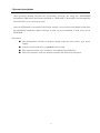
1
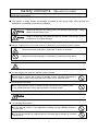
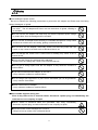
POKAYOKE TRANSMITTER
【TWF‐600T】
Users Manual
V1.03
Safety concerns
(Be sure to read)
To prevent human injury of user or damage in property from occurring, be sure to observe the
precautions shown below.
■ The degree in safety hazard and damage generated by the wrong usage while ignoring the
descriptions is classified by the following displays.
!
Warning
!
Caution
Using in an improper way while ignoring this pictorial symbol might
death or serious human injury.
cause a
Using in an improper way while ignoring this pictorial symbol might cause a
human injury or property damage.
■The type of descriptions you should observe is classified by the following pictorial symbols.
!
This pictorial symbol indicates a “Reminder” to attract an attention.
This pictorial symbol indicates a “Prohibition” to prohibit a certain action.
!
■ For the usage to be commonly applied in all the models:
●Avoid using in a place with a plenty of humidity or dust. Otherwise, absorbing a
dust or water contents may cause machine trouble, fire or electrical shock.
■For handling this machine:
●This is the electronic devise or wireless radios composed of the precision parts.
Do not overhaul/remodel. It may cause accident or machine trouble.
!
Warning
■ For handling this machine:
●Do not use this product for the application needing the high reliability related to
human lives.
●Do not use this product in a place where it is uncertain about whether or not radio
waves reach.
i
!
Warning
■For handling the power source:
Be sure to observe the following precautions to prevent the AC adapter and Power cord from being
heated, damaged, or ignited.
●Do not approximate the AC adapter and Power cord to a fire, or do not put them
into a fire. The AC adapter and Power cord can be broken or ignited, resulting in
an accident.
●You can use the AC adapter and main body only with the specified power voltage
to protect them from the damage and fire accident.
●Do not use the AC adapter and main body in a wettable atmosphere. It may cause
accidents or troubles such as heating, igniting or electrical shock.
●Do not touch the AC adapter, main body, Power cord and Plug outlet with wet
hands. It may cause an accident such as electrical shock, etc.
●Do not damage the Power cord. A short-circuit or heating may cause a fire or
electrical shock.
●Do not use the Power plug with dust being adhered.
A short-circuit or heating may cause a fire or electrical shock.
●Do not give a strong impact onto the AC adapter. It may cause an accident or
machine failure.
●If you find out deformed AC adapter, do not use it.
It may cause an accident or machine failure.
●Do not charge this equipment in a place where flammable gas can be generated.
It may cause a fire accident.
●Never overhaul the AC adapter.
It may cause an accident or machine failure.
■When trouble happens during use:
Since it may cause a fire or electrical shock, disconnect a power plug, and immediately ask
outlet store or our company to repair.
● When smoke or abnormal odors are generated, stop using, immediately
disconnect a power plug, and ask outlet store or our company to repair.
●Once the Power cord is damaged, do not use it.
Using it as is may cause a fire or electrical shock.
ii
!
CAUTION
INFORMATION ABOUT FCC STANDARD
FCC WARNING!
CHANGE OR MODIFICATIONS NOT EXPRESSLY APPROVED BY THE MANUFACTURE
FOR COMPLIANCE COULD VOID THE USER’S AUTHORITY TOOPERATE THE
EQUIPMENT
THE FOLLOWNG APPLIES ONLY IN THE U.S.A
This device complies with Part 15 of the FCC Rules. Operation is subject to the following two
conditions:
(1) This device may not cause harmful interface, and
(2) This device must accept any interface received, including interface that may cause
undesired operation:
TO REDUCE THE ELECTRIC SHOCK, DO NOT REMOVE SCREWS.
NO USER-SERVICEABLE PARTS INSIDE.
REFER SERVICING TO QUALIFIED SERVICE PERSONNEL.
This telecommunication equipment conforms to NTC technical requirement
iii
Contents
1.General descriptions .............................................................................................................. 1
2.Specifications .......................................................................................................................... 2
3.Dimensional drawing ............................................................................................................. 3
4.To install on the Torque wrench .......................................................................................... 6
4-1.Preparation for installation ................................................................................................... 6
4-2.Installation ............................................................................................................................. 8
5.How to use Radio Transmitter ........................................................................................... 10
5-1.Checking the battery ........................................................................................................... 10
5-2.Operating timing ................................................................................................................. 10
5-3. Replacing the battery ......................................................................................................... 11
6.Registering ID ........................................................................................................................ 12
7. Precautions during use ............................................................................................................ 13
8. Troubleshooting ....................................................................................................................... 14
9.Guarantee ................................................................................................................................ 15
1.General descriptions
This operation manual contains the instructions necessary for using the “POKAYOKE
Transmitter TWF-600T” (hereinafter specified as “TWF-600T”). Thoroughly read through this
manual before use to correctly operate.
Once the TWF-600T is mounted on the Torque wrench a tool of others with Limit switch (LS),
the tightening completion signal of Torque wrench can be transmitted to each series of our
TWF-600R.
<Features>
●
This Transmitter consists of compact design using the coin battery type power
supply.
●
Noiseless weak radio wave of 426MHz-band is used.
●
The antenna-built-in type is superior in handling (controllability).
●
The Polycarbonate resin case mounted enables the dust & oil mist proof.
1
2.Specifications
Items
Remarks
Specifications
Reference standard
FCC Part15.231
Mode of operation
Simplex
Transmit frequency
426.1MHz
Emission designation
F1D
Type of modulation
FSK
Transmission data rate
1000bps
Transmit system
Crystal oscillation frequency multiply
system
Antenna type
Built to the foundation
ID
65526(16bit) exclusive, unique ID
Assigned
before shipment
Comm.distance
Approx. 30m radial
※1
Indicator
Power voltage reduction alert LED
Power source
Coin-type lithium battery
CR2032(3V 220mh)
Battery life
Approx. 150,000 times or more
As measured at one
second interval
Power consumption
12mA or less
Ta25℃
Operating temperature range
0℃ to 50℃
Outside dimensions
W32.0×D71.0×H17.5mm
Weight
40g
Including
base and battery
※1 Communication may be disabled in a place with large radiant noise such as noise from
electric welding machines
2
3.Dimensional drawing
Label
Case fixing screw
Battery check window
Seat fixing screw
Limit switch (SS-01GL)
3
3.Dimensional drawing
Silicon caulking for fixing board
Battery case
Battery (CR203)
Packing
Seat(Case holder)
Seat
Battery holder
4
34mm
3.Dimensional drawing
17.5mm
71mm
16.3mm
Lead wire length
approx.20mm
32mm
61mm
18mm
26mm
2-φ4.5×8mm
12.2mm
5mm
30.8mm
8mm
54mm
71mm
M3
Battery holder approx.φ13×5.8
4mm
5.6mm
34mm
2-φ4.5mm
10mm
5
55mm
4.To install on the Torque wrench
4-1.Preparation for installation
1)
Check the parts necessary for installation.
Torque wrench with Limit SW(LS) (User shall prepare)
Note)Depending on the type of Torque wrench, transmitter may not be installed. Contact our sales office.
Transmitter and a set of accessories
Seat ×1
(with Battery holder)
Transmitter body×1
(with Limit SW)
Battery×1
CR2032
2)
(3V)
Fixing screw×4
Set screw×1
(M4×L5)
(M3×L7)
Tools necessary for installation
・Allen wrench
:
Size 1.5mm
・Phillips screwdriver
:
Size #2
・Screw locking agent
・ Prick punch (sharp edge)
6
4.To install on the Torque wrench
3)
Remove the Cover and Limit SW.
②
Remove two hexagon socket head
bolts(※1), and remove the Limit SW.
①
※1
Remove four fixing screws, and remove the cover.
Since two hexagon socket head bolts(with washer) should be used later, do not lose them.
Because the limit SW mounted with Torque wrench as standard has the different current
capacity, do not use it.
Weld bead
③
Verify that the Seat of Torque wrench is flat.
If the weld bead is protruded from the Seat, grind it.
7
4.To install on the Torque wrench
4-2.Installation
1)
To install the Seat
Fix the Seat with four fixing screws.
・
・
For the application with heavy oil mist, fill up the caulking agent between Wrench
seat and Seat and also between Wrench shaft and Wrench seat to protect the internal board.
Apply the screw locking
agent onto the 2 to 3 threads
of screw edge.
2)
Fix the Transmitter Limit SW with two hexagon socket head bolts(which was
removed).
・
Verify that the moving range of wrench lever is well suited for the movement range of
switch during the wrench in movement.
The hexagon socket head bolt requires a washer.
Apply the screw locking agent on 2 to 3
threads of hexagon socket head bolt.
Wrench lever
8
4.To install on the Torque wrench
Hook the Transmitter on the Case holder of Seat, set it with an attention being paid
4)
not to bite the cord, and fix it with the set screw as firmly pushing the case.
Case holder
9
5.How to use Radio Transmitter
5-1.Checking the battery
The transmitter has a battery voltage checking LED. It lights up when the voltage of the
battery in use is running low to alert the battery replacing time. The LED lights up when
the battery voltage lowers below 2.3V(but does not light up during transmission)
Check if the LED is lit
5-2.Operating timing
・The following figure shows the operating timing of Limit switch/Transmitter.
<Limit switch>
Set the Limit switch ON time at 10mS or over.
Keep 10ms or over in shot interval.
500ms or over(※1)
<Transmitter>
Electric wave is emitted for about 142ms.
※1 This interval time should be more than the double counting prevention time of Receiver.
The Receiver has the double count prevention function to avoid the double counting.
For detail of double counting prevention time, see the operation manual of each receiver.
10
5.How to use Radio Transmitter
5-3. Replacing the battery
Pull out the fixing screw from Transmitter, and disassemble it from the Seat.
Take out the battery in the direction of ② while pushing it in the direction of ①.
②
①
Insert the battery from the direction of ①,
push it in the direction of ②,
return it in the direction of ③, and then mount it.
①
②
③
It is no need to remove the Limit switch.
Use a care not to break the cord.
※When new battery is fixed, radio wave may be emitted by one shot.
11
6.Registering ID
An exclusive, unique ID is assigned to each device before shipment.
The data sent from this device is composed of 2 Frames, each frame having the fixed length
equivalent to 8 blocks and 66 bits.
For an ID, 24 bits in one data frame are used. Normally, 16bits out of 24 bit are used to
assign 65536 different Ids.
Confirm the ID of your receiver and set the ID on the receiver(TWF-600R) accordinary.
When you want to know the details about TWF-600R, please read instruction manual
[TWF-600R].
12
7. Precautions during use
■This machine is the precision equipment covered with plastic frame. Do not give an excessive impact.
■Use a care during setting as the Dip Switch for setting ID can be easily damaged.
Carefully make setting using the edged tool like Prick punch.
■Shift the battery to the arrow mark side before disconnecting the battery.
■Do not use the edged tool like prick punch when pressing the Test switch.
(Use an extreme care not to damage the Pawl of Battery holder during replacement of battery.)
■Use a care not to bite the cable of Limit switch when replacing a battery or changing the ID setting.
13
8. Troubleshooting
〔Normal communication does not run〕
■Is the battery used up?
→Check if battery check LED lights on.
■Are “Radio frequency and ID” different from those of Receiver?
→Check the Receive for its channel and ID.
■Is this machine used outside the radio wave access range?
→Use this machine within the radio wave access range.
■Is the moving range of wrench lever is out of the movable range of limit switch during operation of
wrench?
→Verify the Limit switch for its installation.
■Is a noise generated?
→If communication does not run during a given time zone or due to the operation of the specific
device, noise might be generated.
14
9.Guarantee
This product passed it by our close product inspection. When it broke down under the normal use
of a visitor by any chance, we will repair a trouble point according to a rule, please report to a
store of purchase. However we are limited to hardware of this product.
In addition, we become charged repair in the case of next even if I put it before a term of a
guarantee.
1. In the case of trouble / the damage that occurred because the handling was not reasonable of a
visitor such as a fall at the time of the transportation / movement by a visitor, a shock.
2. In the case of trouble by the resolution and remodeling of the main body by a visitor.
3. In the case of natural calamities in heaven and earth such as a fire / an earthquake / a flood and
trouble / the damage by abnormal voltage.
4. In the case of trouble / the damage due to trouble of machinery except our designated machinery
connected to this product.
5. Accessories (AC adapter, an antenna, a connection cable) except the main body do not include it.
6. In the case of the trouble that occurred by the handling against usage mentioned in this instruction
manual and instructions.
●The guarantee certificate is attached on this product. Confirm the prescribed contents, and
carefully keep it.
●The guarantee period is one year.( The guarantee certificate is not attached on this product.)
We will repair during the guarantee period according to the guarantee provisions without charge.
●For the repair after guarantee period, consult the outlet store through which you purchased or our
sales office.
If the function can be preserved by the repair, we will repair it at some costs on the customer
request.
●As a principle, regardless of the guarantee period, the defect product should be brought into our
company because the measuring instrument is required for adjustment during repair. Besides, the
customer shall bear the transportation cost incurred during transferring to our company.
If you need official trip repair or replacement machine during guarantee period, consult the outlet
store through which you purchased or our sales office.
●If you have unclear points for the repair or after service during the guarantee period, consult the
outlet store through which you purchased or our sales office.
15
9.Guarantee
● The contents in this manual are subject to change without prior notice.
● We take all possible measures for the contents stated in this manual, however,
if it contains doubtful points, contact our sales office.
● We shall not be responsible for any influences resulting from use of this
machine regardless of aforementioned provisions.
● The product specification and appearance are subject to change for further
improvement without prior notice.
16
<CONTACT US>
HERUTU ELECTRONICS CORPORATION
62-1 Toyooka-cho, Kita-ku, Hamamatsu-shi, Shizuoka-ken, 433-8103 Japan
Tel.81-53-438-3555
Fax.81-53-438-3411
URL: http://www.herutu.co.jp
Mail: [email protected]
V20070510