1
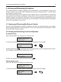
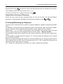
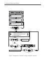
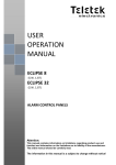
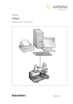
AVA
WIRELESS SECURITY SYSTEM
USER’S MANUAL
Carefully read through this manual prior to installing and programming the
system!
Teletek Electronics JSC
Sofia, November 2005
2
Guarantee
Guarantee
During the guarantee period the manufacturer shall, at its sole discretion, replace or repair any defective
product when it is returned to the factory. All parts replaced and/or repaired shall be covered for the remainder
of the original guarantee, or for ninety (90) days, whichever period is longer. The original purchaser shall
immediately send manufacturer a written notice of the defective parts or workmanship, which written notice
must in all cases be received prior to expiry of the guarantee.
International Guarantee
Foreign customers shall enjoy the same guarantee rights as those enjoyed by any customer in Bulgaria, except
that manufacturer shall not be liable for any related customs duties, taxes or VAT, which may be payable.
Guarantee Procedure
This guarantee will be granted when the appliance in question is returned. The manufacturer shall accept no
product whatsoever, of which no prior notice has been received.
Conditions for waiving the guarantee
This guarantee shall apply to defects in products resulting only from improper materials or workmanship, related
to its normal use. It shall not cover:
§ Damages resulting from transportation and handling;
§ Damages caused by natural calamities, such as fire, floods, storms, earthquakes or lightning;
§ Damages caused by incorrect voltage, accidental breakage or water; beyond the control of the
manufacturer;
§ Damages caused by unauthorized system incorporation, changes, modifications or surrounding objects;
§ Damages caused by peripheral appliances unless such peripheral appliances have been supplied by the
manufacturer;
§ Defects caused by inappropriate surrounding of installed products;
§ Damages caused by failure to use the product for its normal purpose; Damages caused by improper
maintenance;
§ Damages resulting from any other cause, bad maintenance or product misuse.
In the case of a reasonable number of unsuccessful attempts to repair the product, covered by this guarantee,
the manufacturer’s liability shall be limited to the replacement of the product as the sole compensation for
breach of the guarantee. Under no circumstances shall the manufacturer be liable for any special, accidental
or consequential damages, on the grounds of breach of guarantee, breach of agreement, negligence, or any
other legal notion.
Waiver
This Guarantee shall contain the entire guarantee and shall be prevailing over any and all other guarantees,
explicit or implicit (including any implicit guarantees on behalf of the dealer, or adaptability to specific purposes),
and over any other responsibilities or liabilities on behalf of the manufacturer. The manufacturer does neither
agree, nor empower, any person, acting on his own behalf, to modify or alter this Guarantee, nor to replace
it with another guarantee, or another liability with regard to this product.
Unwarranted Services
The manufacturer shall repair or replace unwarranted products, which have been returned to its factory, at its
sole discretion under the conditions below. The manufacturer shall accept no products for which no prior notice
has been received.
The products, which the manufacturer deems repairable, will be repaired and returned. The manufacturer has
prepared a price list and those products, which can be repaired, shall be paid for every repaired appliance.
The closest equivalent product, available at the time, shall replace the products manufacturer deems unrepairable.
The current market price shall be charged for every replaced product.
3
Contents
Contents
Guarantee .......................................................................................... 2
1. General .......................................................................................... 4
1.1 LED Indication ................................................................................. 4
1.2 Sound Indication ............................................................................. 4
2. Arming and Disarming the System .............................................. 5
2.1 Arming and Disarming By Remote Control ................................... 5
2.2 Arming and Disarming From the Keyboard .................................. 5
2.3 Arming/Disarming by Telephone ................................................... 6
3. System State .................................................................................. 8
4. Bypassing Detectors or Groups of Detectors ......................... 10
5. Review of the Event LOG .......................................................... 10
6. User’s Programming ................................................................... 11
7. System Adjustments .................................................................... 13
8. User’s Menus .............................................................................. 15
4
1. General
1. General
The AVA Wireless Security System is designed for establishing domestic and small office
alarm security systems. The connection between the various components of the security
system is wireless, based on radio-communication with a frequency of 868 MHz.
The AVA set includes modules meeting all requirements for an alarm security system – sirens
for indoor and outdoor installation, magnetic contact, infrared detector, fire optical-smoke
detector, digital communicator, remote controls and keypad with liquid crystal display.
The maximal number of system users is 16. Every user, depending on the rights assigned by
the system installer, can arm or disarm the system security, bypass detectors and modules,
change his own code, program the other codes, review the list of events in the system, check
the system clock, as well as many other functions.
In order to gain access to the available functions and parameters, the user has to enter his
code. Access to specific functions and parameters will depend on the individual user rights.
Security control can be exercised through the liquid crystal display keyboard built into the AVA
box, the remote control, and wireless keypad with liquid crystal display or over the telephone.
The digital communicator enables the establishment of an acoustic connection with the armed
premises. It is possible to hear out these premises as well as to hold a conversation with them.
1.1 LED Indication
There are 4 LED indicators for the main events in the system on the LCD keypad display,
integrated into the control panel box.
220V AC – lights up in green to indicate main power supply; extinguishes to indicate main
power supply failure.
TROUBLE – lights up in yellow in case of System Tamper; blinks in case of System Trouble.
It is recommended to call your installer.
ALARM – lights up in red in case of an alarm event; blinks during entry or exit times.
FIRE – lights up in red to indicate a fire event.
1.2 Sound Indication
The following sound indications have been integrated within the AVA:
Short beep – upon pressing any key.
Continuous beep – refusal to perform an action.
Continuous sound, followed by a chime – confirmation signal.
Interrupted sound signal – exit time is running.
Quick interrupted sound signal – exit time is running or an important event has occurred
such as Tamper, Fire, etc.
Double sound signal every 20 seconds – in the case of technical system problems.
2. Arming and Disarming the System
5
2. Arming and Disarming the System
The security system is readily available to be armed when – all area detectors, likely to be
armed, must be in an inactive state. Readiness for arming is indicated by the “-” symbol below
the respective system area.
AVA can provide short sound signals from the System sirens in confirmation of successfully
executed Arm and Disarm commands. Where this function has been programmed by the
System installer, the successful execution of the Arm command shall be confirmed by two
short activations of the sirens, and the execution of the Disarm command shall be confirmed by
three short activations of the sirens.
2.1 Arming and Disarming By Remote Control
Press the key designated to execute a respective function, as programmed by your installer.
When pressed, the built-in LED should blink in red. If the command is received by the Control
Panel, the LED will blink in green.
2.2 Arming and Disarming From the Keyboard
Arming Security:
Enter the User Menu by entering your access code:
123456 Thu.29/07
code[****]
If correctly introduced there will be a confirmation signal from the keypad.
User Menu
AR
M
ENT
ARMing
Single press the key
AR
M
and with the help of the digit buttons enter the selected Arm function.
The available numbers of the functions are 1 to 6.
ARMing
Arm Fn N: 1
Confirm the selection by single pressing the key
ENT
.
Disarming Security:
Enter the User Menu by dialing your access code:
123456 Thu.29/07
code[****]
If correctly introduced there will be a confirmation signal from the keypad.
User Menu
ARMing
DIS
AR
M
6
Single press the key
2. Arming and Disarming the System
DIS
AR
M
and with the help of the digit buttons enter the selected Arm function.
The available numbers of the functions are 1 to 6.
Confirm the selection by single pressing the key
ENT
.
Single Button Arming and Disarming
Where the user code has been assigned rights for only one function, the Arm and Disarm
procedure is automatically completed by pressing the respective key
AR
M
or
DIS
AR
M
.
2.3 Arming/Disarming by Telephone
The AVA can be controlled from a mobile or ordinary telephone, capable of reproducing DTMF
tones.
To establish a connection dial the telephone number of the System. After connection is established, a specific sound, produced by the System, will be heard from the receiver.
Single press “ * ” or “ # “. Enter a valid system code, followed by two random digits. The code
which is being used must be assigned Remote Control rights - “Remote Access”.
A confirmation signal will be heard from the receiver when the code has been entered correctly.
On the telephone keypad enter the symbols “*9”. This will switch the System over to remote
control mode of security.
Enter the number of the desired function for arming or disarming. For arming function enter a
value between 001 and 006, and for disarming enter 101 to 106. A signal confirming the set
command will be heard from the receiver.
Fig. 1 shows the consequence of activities for using a telephone connection
2. Arming and Disarming the System
7
Wait for signal from AVA system
Press once button * or #
Enter 6 digit valid code
No
Yes
0 - Listening to the AVA’s premises
1 - Talking to the AVA’s premises
2 - Listening and talking to the AVA’s premises
3 - Amplified listening to the AVA’s premises
*9 - Remote Arming/Disarming
99 - Hang up connection
Yes
Switches on respective
acoustic function
No
No
Yes
No
Yes
Pressing 99 hangs up the connection
Figure 1 Consequence of activities for using a telephone connection
8
3. System State
3. System State
Every user has access to 5 menus where the state of the System can be checked. To gain
access to these menus enter a valid user code and then single press
User Menu
TRB
TRBL (troubles)
TRB
L
.
L
Technical Trouble Review
Single press
1
and the display will automatically show current technical problems:
TRBL (troubles)
1)System troubles
AC loss
Main BATT
fuse
module BATT
maintenance
comm. ERR
line fault
RFinterference-
no main power supply
low charge level or burnt out battery fuse
burnt out auxiliary power supply fuse
low battery charge in any of the modules
low temperature or FD requires servicing
telephone communication trouble
telephone line trouble
currently not maintained
Review of System Areas not ready to be Armed
Single press
Armed:
2
3. System State
and the display will automatically show the areas, which are not ready to be
TRBL (troubles)
2)Open Groups
G01 +L- Entry/Exit
Group name
Review of Currently Active Detectors
Single press
to be Armed:
3
and the display will automatically show the detectors, which are not ready
TRBL (troubles)
3)Open Devices
01PIR
#õõõõõõ
Device name
9
3. System State
Single press
state:
4
and the display will automatically show all the areas and will indicate their
TRBL (troubles)
4)Group state
G01 +L- Entry/Exit
Group name
Review of System module state
Single press 5 and the display will automatically show all modules in the System and will
indicate their state:
TRBL (troubles)
5)Devices state
01PIR
#õõõõõõ
Device name
Use the arrows
to switch over from automatic to manual review mode.
The symbols indicating the state of the System modules are:
Fire
Tamper
Alarm
Memory
Low battery charge level of the main System module
Low battery charge level of a System module
No connection with module
Burnt out fuse
Armed
Armed with bypassed detectors
Requires engineer supervision
Bypassed module
Disallowed module
Area is ready to Arm
Open area
The information contained in the event memory is as follows:
10
4. Bypassing Detectors or Groups of Detectors
4. Bypassing Detectors or Groups of Detectors
Individual detectors can be bypassed where necessary. When bypassed their state will have
no effect when the System is armed.
In order to bypass detectors introduce a valid user code.
Single press
BP
S
single pressing
. Use the arrows to select Bypass or No Bypass. Confirm the selection by
ENT
.
User menu
BPS
ARMing
Use the arrows
to position on the desired detector and then single press
01PIR
#õõõõõõ
ENT
.
ENT
Device name
Device name
1)Bypass Device
ENT
Use the arrows to select Bypass or No Bypass. Confirm the selection by single pressing
ENT
.
1)Bypass Device
Not BYPASSED
1)Bypass Device
4. Bypassing Detectors or Groups of Detector
ENT
bypass?
When disarming, the System automatically restores the bypassed detectors which belong to
disarmed Areas.
5. Review of the Event LOG
The System records the latest 256 events by time and date of occurrence. These events are
available for review by the user. For this purpose the respective user needs to have been
assigned the relevant right.
In order to review the events enter a valid user code and single press
User menu
ME
ARMing
Events can be viewed with the help of the arrows
ME
M
.
M
. It is possible to switch over
to a screen with a detailed description of the event. The switch over between the two screens
can be done by single pressing
PRG
.
6. User’s Programming
11
008 29/07 19:18
EV_BURG_ALARM
The event displayed is 8th on the row of the list. The type of event is a Burglary Alarm event
having occurred at 7.18 p.m. on 29 July. Detailed information will be displayed by single
pressing
PRG
:
G:02 Group name
D:01 Device name
6. User’s Programming
The System maintains 16 user codes. Depending on their programmed rights the users avail of
access rights to various menus.
In order to program the user codes and their rights introduce a valid code and then single press
PRG
.
User Menu
ARMing
PROGramming
PRG
ENT
1)User Codes
rs
Use the arrows
press
ENT
to position on the user code to be programmed and single
.
Code 01 ***/---Code name
In order to change the digital configuration of the code, go to 1)Change Code and single
press
ENT
.
Code name
ENT
1)Change code
Introduce the new code combination twice.
Code name
new code:[****]
Code Name
confirm:[****]
In order to change the name of the code, go to 2)Change Name and single press
ENT
.
* DARM f-n N6
In order to program user code attributes go to 5)CodeAttributes and single press
ENT
.
12
6. User’s Programming
Code name
ENT
2)Change name
Use the digit keys to enter the new code name. The length of the name should not exceed 8
letters. Confirm the new name by single pressing
2)Change name
ENT
.
ENT
Code name
In order to edit code rights for arming the System, go to 3)Arming Rights and single press
ENT
.
Code name
ENT
3)Arming Rights
Use the arrows to position on the arm function, needed to program the desired code. Press
to mark and unmark in sequence the selected function. Confirm programming by single
PRG
pressing
ENT
.
3)Arming Rights
ENT
*ARM f-n N1
* ARM f-n N2
* ARM f-n N3
* ARM f-n N4
* ARM f-n N5
* ARM f-n N6
In order to edit code rights for disarming the System, go to 4)Disarm.Rights and single press
ENT
.
Code name
ENT
4)Disarm.Rights
Use the arrows to position on the disarm function, needed to program the desired code. Press
PRG to mark and unmark in sequence the selected function. Confirm programming by single
pressing
ENT
.
4)Disarm.Rights
*DARM f-n N1
*
*
*
*
DARM
DARM
DARM
DARM
f-n
f-n
f-n
f-n
N2
N3
N4
N5
ENT
13
7. System Adjustment
Code name
ENT
5)CodeAttributes
5)CodeAttributes
-Manager
* Manager
- can program remaining codes
* Bypass
- can bypass
* Log view
- can view the Log of Events
* Time/Data set
- can adjust the time
* Remote Access
- allows access by telephone line
In order to change the digits configuration of the personal code go to 2)ChangeOwn Code
and single press
ENT
. The codes without a Manager attribute can only change their own
digits combination.
PROGramming
ENT
2)ChangeOwn Code
2)ChangeOwn Code
new code:[****]
The new code combination shall be entered two times for authenticity.
2)ChangeOwn Code
confirm:[****]
7. System Adjustments
Every user has access to four menus to make system adjustments. In order to access these
menus enter a valid user code and single press PRG . Then single press 3 .
PROGramming
3)System
3)System
1)Date and Time
To change the date and time single press
by single pressing
ENT
1
. Enter the date and time and confirm the change
.
1)Date and Time
ENT
2004 24/05 12:53
To change the type of the display single press
the parameters. Press
PRG
2
. Use the arrows
to position on
to mark and unmark. Confirm the change by single pressing
ENT
.
7. System Adjustment
14
3)System
2)Display
2)Display
*Chime on entry
* Chime on entry
* display Groups
For display backlight corrections single press
3
- emits a “chime” sound when a detector is
activated in an entry/exit type zone
- indicates the statues of areas
.
3)System
3)Backlight
With the help of the arrows
the change by single pressing
adjust the required brightness of the backlight. Confirm
ENT
.
3)Backlight
<>: 3
In order to change the language of the captions press
select the language. Confirm by single pressing
4)Language
áúëãàðñêè
english
4
ENT
. With the help of the arrows
.
8. User’s Menus
15
8. User’s Menus
ARMing
DISARMing
BPS Device
1)Bypass Device
TRBL (troubles)
1)System troubles
2)Open groups
3)Open devices
4)Group state
System troubles
AC loss
Main BATT
fuse
module BATT
maintenance
comm. ERR
line fault
RF interference
5)Devices state
Memory Log
PROGramming
1)User codes
1)Change code
2)Change name
3)Arming Rights
4)Disarm. Rights
5)Code Attributes
2)Change Own Code
3)System
1)Date and Time
2)Display
3)Backlight
4)Language
Rev. D 11/2005, 18020409