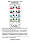
1
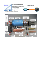
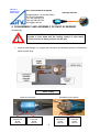
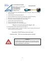
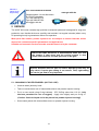
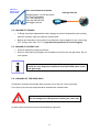
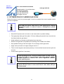
Plasma &
Flame Spray
Engineering
GTV Verschleißschutz GmbH
www.gtv-mbh.de
Gewerbegebiet: Vor der Neuwiese
D-57629 Luckenbach
Tel: +49 2662/9576-0
Fax:+49 2662/957630
[email protected]
OPERATORS MANUAL
GTV HVOF K2
Burner
780.000
1
Plasma &
Flame Spray
Engineering
GTV Verschleißschutz GmbH
www.gtv-mbh.de
Gewerbegebiet: Vor der Neuwiese
D-57629 Luckenbach
Tel: +49 2662/9576-0
Fax:+49 2662/957630
[email protected]
EG - DECLARATION OF CONFORMITY
According to EG- Machine Guideline 98/37/EG, Annex II A
EG-Guideline Electrical Magnetically Amicability 89/336/EWG
EG- Guideline „Low Voltage“ 93/68/EWG
Machine:
PLANT:
HVOF Equipment
TYPE:
K2 Torch
PRODUCTION DATE:
2005
Project No.
780.000
IS DEVELOPED AND DESIGNED ACCORDING THE ABOVE MENTIONED NORMS IN
FULL RESPONSIBILITY OF
Incorporation:
GTV Verschleiss-Schutz GmbH
Company Location:
Gewerbegebiet, D-57629 Luckenbach, Germany
FOLLOWING STANDARDS:
•
•
•
•
DIN EN 12100
DIN EN 1050
DIN EN 60204-1
BGR 500
Safety of equipment, components and machine units
Guidance for risk assessment
Electrical setup for equipment and machines
Gases
THIS DECLARATION LOSES VALIDITY, IF CHANGES TO THE EQUIPMENT WILL BE
DONE WITHOUT GTV AGREEMENT.
Luckenbach, 03.07.2008
Directory Manager
2
Plasma &
Flame Spray
Engineering
GTV Verschleißschutz GmbH
www.gtv-mbh.de
Gewerbegebiet: Vor der Neuwiese
D-57629 Luckenbach
Tel: +49 2662/9576-0
Fax:+49 2662/957630
[email protected]
1 GENERAL DESCRIPTION:
1.1 INTRODUCTION HVOF
Since it’s first application 20 years ago, High Velocity Oxygen Fuel (HVOF) spraying has
gained increasing importance in the thermal spray market.
The special feature of this technique, as compared to other TS techniques, is that the
coating materials are less heated and impact on the components which are to be coated
with remarkably higher velocities.
In HVOF systems a flame is created by combustion under high pressure, resulting in gas
velocities of more than 2000 m/s. The spray powder is injected into this gas stream.
1.2 HVOF K2 SYSTEM
The HVOF K2 System is a HVOF System of the third generation. Instead of a fuel gas this
system uses a liquid fuel (kerosene).
The system operates at combustion chamber pressure typically up to 10 bar. The powder is
injected radially into the gas stream, just behind the point of divergence.
For the case of WC/Co powder, this system allows a spray rate of up to 10 kg/h without
affecting coating quality.
Physical Comparison
Fuel
Propane
Hydrogen
Ethen
Acetylen
Kerosene
Max. Flametemperature
[C°]
2800
2900
3000
3160
2800
Heat value
[MJ/m3]
Oxygen/Fuel Ratio Oxygen/Fuel
For
a
max. Ratio for a
Temperature
neutral flame
4.5
5.0
0.42
0.5
2.4
3.0
1.5
2.5
2.9 1)
3.4 1)
93
11
60
60
38 MJ/l
1) mass ratio oxygen/kerosene
3
Plasma &
Flame Spray
Engineering
GTV Verschleißschutz GmbH
www.gtv-mbh.de
Gewerbegebiet: Vor der Neuwiese
D-57629 Luckenbach
Tel: +49 2662/9576-0
Fax:+49 2662/957630
[email protected]
During combustion of liquid fuel and oxygen chamber pressures of 10 bar and more
are generated. This results in jet velocities of more than 2000 m/s. The generated
heat is roughly doubled compared to gas operated systems. Temperatures of
maximum 2.800°C are achieved.
Using the GTV HVOF K2 burner thermal spray coatings with low porosity (< 1%)
high bond strength (> 100 MPa), low oxidation and high resulting hardness can be
achieved.
Another advantage is that coatings with highly compressive residual stress can be
sprayed reaching several millimeters thickness.
The power of the kerosene oxygen mixture is more than 250 kW (about 10 kW per
liter kerosene). Thus feed rates of 10 kg/h can be realized.
1.3 WATER QUALITY
Use water with a low hardness (about degree 2 hardness).
Lime accumulation could damage the torch.
1.4
FUEL QUALITY
EXXSOL D 60
4
Plasma &
Flame Spray
Engineering
GTV Verschleißschutz GmbH
Gewerbegebiet: Vor der Neuwiese
D-57629 Luckenbach
Tel: +49 2662/9576-0
Fax:+49 2662/957630
[email protected]
2 GTV HVOF K2 BURNER
5
www.gtv-mbh.de
Plasma &
Flame Spray
Engineering
GTV Verschleißschutz GmbH
www.gtv-mbh.de
Gewerbegebiet: Vor der Neuwiese
D-57629 Luckenbach
Tel: +49 2662/9576-0
Fax:+49 2662/957630
[email protected]
3 GTV HVOF K2 BURNER SPARE PARTS
GTV-no.
description
780.110-100
water jacket – 100 mm
780.110-150
water jacket – 150 mm
780.110-200
water jacket – 200 mm
780.111
o-ring water jacket
780.120-100
Intermediate sleeve – 100 mm
780.120-100 k
Intermediate sleeve – 100 mm conic
780.120-150
Intermediate sleeve – 150 mm
780.120-150 k
Intermediate sleeve – 150 mm conic
780.120-200
Intermediate sleeve – 200 mm
780.121
o-ring Intermediate sleeve
780.130
powder injector section
780.131
powder injector
780.132
screw
780.133
o-ring powder injector section (outside front)
780.134
o-ring powder injector section (outside rear)
780.135
o-ring powder injector section (inside front small)
780.136
o-ring powder injector section (inside rear)
780.137
o-ring powder injector section (inside front big)
780.140
main body
780.141
o-ring main body
780.142
t-clamp holder
780.143
screw for t-clamp holder
780.145
hand nut
780.146
screw
780.160
combustion chamber
780.170
rear body assembly
6
Plasma &
Flame Spray
Engineering
GTV Verschleißschutz GmbH
www.gtv-mbh.de
Gewerbegebiet: Vor der Neuwiese
D-57629 Luckenbach
Tel: +49 2662/9576-0
Fax:+49 2662/957630
[email protected]
780.171
o-ring rear body small
780.172
o-ring rear body big
780.180
atomizer connection
780.182
screw
780.183
o-ring atomizer connection big
780.184
o-ring atomizer connection small
780.190
spark plug
780.500
o-ring set
780.000
GTV HVOF K2 burner
expansion nozzle
GTV-no.
description
diameter
length
780.150-100/10
expansion nozzle
10 mm
100 mm
780.150-100/11
expansion nozzle
11 mm
100 mm
780.150-100/12
expansion nozzle
12 mm
100 mm
780.150-100 k
Expansion nozzle
conic
100mm
780.150-150/10
expansion nozzle
10 mm
150 mm
780.150-150/11
expansion nozzle
11 mm
150 mm
780.150-150/12
expansion nozzle
12 mm
150 mm
780.150-150 k
Expansion nozzle
conic
150mm
780.150-200/10
expansion nozzle
10 mm
200 mm
780.150-200/11
expansion nozzle
11 mm
200 mm
780.150-200/12
expansion nozzle
12 mm
200 mm
7
Plasma &
Flame Spray
Engineering
GTV Verschleißschutz GmbH
www.gtv-mbh.de
Gewerbegebiet: Vor der Neuwiese
D-57629 Luckenbach
Tel: +49 2662/9576-0
Fax:+49 2662/957630
[email protected]
4 DISASSEMBLY AND ASSEMBLY OF HVOF K2 BURNER
Disassembly:
Before the HVOF K2 burner is disassembled, make sure that the
system is shut down and the cooling system is shut down!
There must be no water pressure on the gun!
1. Unscrew hose fittings for: oxygen gas, kerosene and chamber pressure. Disconnect
cable to spark plug.
water supply
Lower circuit points
Return
Right-hand
thread
780.148
Backward circuit points
Flow
Left-hand
thread
780.147
Return
Right-hand
thread
780.148
8
Flow
Left-hand
thread
780.147
Plasma &
Flame Spray
Engineering
GTV Verschleißschutz GmbH
www.gtv-mbh.de
Gewerbegebiet: Vor der Neuwiese
D-57629 Luckenbach
Tel: +49 2662/9576-0
Fax:+49 2662/957630
[email protected]
2. Take HVOF Burner from manipulator and clamp burner with T-clamp into vise using
aluminum pads.
3. Unscrew spark plug using spark plug tool.
4. Unscrew headless screws (3pieces) on locking ring. Unscrew locking ring.
5. Disconnect rear gun body together with combustion chamber.
6. Disconnect combustion chamber from rear gun body.
7. Unscrew water jacket using hands only.
8. Push out intermediate sleeve backwards.
9. Take off nozzle barrel out of intermediate section.
There is no tool necessary for step 5 –9!
10. Unscrew both powder injectors using wrench SW 11.
11. Unscrew hexagon screws (6 pieces) of powder injector housing and disconnect
injector housing out of the main body.
Assembly of HVOF Burner works vice versa!
Important note: First mount powder injector housing!
!! Danger !!
The HVOF K2 torch should only be connected and operated
on a GTV designed plant. Otherwise any warranty expires as
well as responsibility of GTV GmbH.
9
Plasma &
Flame Spray
Engineering
GTV Verschleißschutz GmbH
www.gtv-mbh.de
Gewerbegebiet: Vor der Neuwiese
D-57629 Luckenbach
Tel: +49 2662/9576-0
Fax:+49 2662/957630
[email protected]
5 SERVICE
The HVOF K2 burner contains high precision mechanical parts and is designed for long term
production use. Handle the burner carefully and maintain it at regular intervals (about every
50 operating hours) to guarantee a failure-free operation.
Wear parts like nozzles, powder injectors etc. are subject to shorter intervals, which
depend on customers specific parameters and applications.
Suitable and economic service intervals must be found out by the customer.
Before the HVOF K2 Burner is disassembled, make sure that
the system is shut down and the cooling system is shut
down! There must be no water pressure on the gun!
Special attention must be paid to nozzle. Operating time may be
very short, if carrier gas setting is not correct. Thus, right setting
for carrier gas flow is very important.
5.1 CHANGING OF NOZZLE BARREL (NO TOOL USE)
•
Unscrew water jacket by hand.
•
Take out nozzle barrel out of intermediate sleeve and powder injector housing.
•
Put in a new nozzle using O-ring lubricant - GTV O-Ring valve lube 112.111 (only
lubricant permitted for use of oxygen!) - Apply lube slightly and put O-ring in.
(Caution: Conical shaped end to be placed into powder injector housing!)
•
Screw water jacket with intermediate sleeve on powder injector housing.
10
Plasma &
Flame Spray
Engineering
GTV Verschleißschutz GmbH
www.gtv-mbh.de
Gewerbegebiet: Vor der Neuwiese
D-57629 Luckenbach
Tel: +49 2662/9576-0
Fax:+49 2662/957630
[email protected]
5.2 CHANGE OF O-RINGS
•
O-Rings should be replaced after each leakage as well as disassembly due to safety
aspects, because rings are subject to thermal load.
•
Before new assembly of gun parts O-ring lubricant must be applied in any case using
GTV O-Ring valve lube 112.111 (only lubricant permitted for use of oxygen!).
5.3 CHANGE OF SPARK PLUG
•
Unscrew spark plug using tool wrench.
•
Screw in new spark plug slightly until resistance is build up by rear gun body. Do not
over tighten!
It must be ensured that the tip of the spark plug is 2 to 3 mm
inside the rear body bore measured from the inside plane of the
rear gun body!
5.4 CLEANING OF THE REAR BODY
Combustion residues accumulate after long-term use of the gun on the rear body.
From time to time the rear body should be cleaned with a brass brush.
Attention!
Do not damage the O-Rings when cleaning the rear body.
All bore holes must be free and not be blocked by impurities.
11
Plasma &
Flame Spray
Engineering
GTV Verschleißschutz GmbH
www.gtv-mbh.de
Gewerbegebiet: Vor der Neuwiese
D-57629 Luckenbach
Tel: +49 2662/9576-0
Fax:+49 2662/957630
[email protected]
5.5 COMBUSTION CHAMBER (780.160)
Combustion residues accumulate after long-term use of the gun on the combustion chamber
wall as well. Therefore the combustion chamber must be checked and cleaned in an
ultrasonic bath, if necessary.
5.6 POWDER INJECTOR BLOCK (780.130)
The powder injector housing is a part, which wears out during powder feeding.
If there is significant erosion on the ring, in which the powder injectors are screwed, the ring
must be rebuilt or the powder injector block must be replaced.
5.7 POWDER INJECTOR (780.131)
The powder injectors are also subject to wear. Wear becomes noticeable by magnification of
the standard diameter. Standard diameter is 1.6 mm. If it passes over 1.7 mm, the injectors
must be changed.
The powder injector must be screwed in the injector block. Do not over tighten. The injectors
tips must stay inside their inner ring bores.
12
Plasma &
Flame Spray
Engineering
GTV Verschleißschutz GmbH
www.gtv-mbh.de
Gewerbegebiet: Vor der Neuwiese
D-57629 Luckenbach
Tel: +49 2662/9576-0
Fax:+49 2662/957630
[email protected]
6 OPTIMIZATION OF CARRIER GAS FLOW
Before the burner is put into process again it must be ensured that correct powder carrier
gas flow is adjusted.
The HVOF K2 burner shall only be used applying two separate
controlled hoppers in order to ensure a homogeneous powder
feeding.
•
Start HVOF process and run burner on set values with no powder feeding.
•
First apply high feed gas flow (about 15 l/min) feeding the powder from one side into
the flame inside the gun barrel.
•
Watch deflection of powder jet while spraying to test piece.
•
Reduce feed gas flow until powder jet is traveling in the middle of the flame.
•
Stop powder feeding of the first hopper. Do not change carrier gas value.
•
Apply same procedure on hopper and gas line No. 2.
•
Then run both hoppers and watch powder jet. Jet should be focused and not split into
two jets.
•
Correct carrier gas flow if necessary.
A spot spraying test on a test piece should show an ideal circular
spray spot. If there is an oval shape of the spray spot no optimal
powder injection is realised and causes significant reduced
nozzle operating time.
If carrier gas flow is not set correctly within short operating time
grooves will be formed in the nozzle barrel. Later water will pour
into the nozzle.
13