1
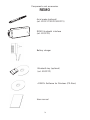
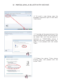
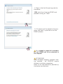
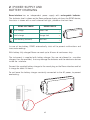
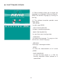
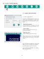
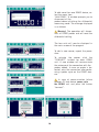
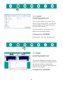
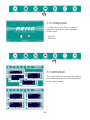
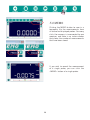
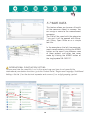
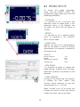
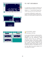
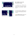
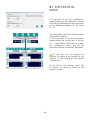
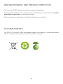
USER MANUAL
REMO
BLUETOOTH INTERFACE FOR AXIAL PROBE
®
Copyright©2013 Microplan®
Documento: MT13.05
Versione: 1
All rights reserved.
Microplan®2013
Components and accessoires
REMO
Axial probe (optional)
(art. ED0217/ED219/ED221)
REMO bluetooth interface
(art. ED0220)
Battery charger
Bluetooth key (optional)
(art. ED0222)
«REMO» Software for Windows (CD-Rom)
User manual
3
1 | INSTALLING A BLUETOOTH DEVICE
1.1 To install a new device, open the
Bluetooth interface on your PC and select
“Add Device.”
1.2. A window will be opened where all the
active bluetooth devices and new devices
are shown. Wait until the new device is
identified as “REMO-XXXX» (where X
identifies the serial number Remo unit),
select it and proceed with the button
“Next”.
1.3 Choose the option “Enter device
binding code” and proceed with the
button “Next”.
1.4 Type in the field the pairing code for
the device:
1234 (valid for all devices REMO) and
proceed clicking on “Next”
1.5 The device will be added to the computer, and now it is possible to run the
REMO software.
It is needed to repeat this procedure
for each REMO unit to be connected to
the computer.
ATTENZIONE!
Some Bluetooth adapters (different from
the standard - art. ED0222) require
different installation procedures.
Refer to the documentation provided by
the device manufacturer.
2 | POWER SUPPLY AND
BATTERY CHARGING
Remo interface has an independent power supply with rechargeable batteries.
The batteries level is shown on the Remo software display, while on the REMO device,
the status is shown with a small coloured led light, placed on the front face:
REMO SOFTWARE
REMO DEVICE
Full charge
Green Led
Half charge
Orange Led
Low battery (auto-off)
Red Led
In case of low battery, REMO automatically shuts off to prevent malfunctions and
inaccurate readings.
With battery fully charged Remo can work up to 6 hours of continuous duty.
The instrument is supplied with battery charger. You are not allowed to use other
chargers than the provided, that may damage the batteries and the electronic devices
inside the interface.
Connect the supplied battery charger to the round plug on the Remo interface and let
it charge for about 16 hours.
Do not leave the battery charger constantly connected to the AC power, to prevent
overheating.
6
3 | SOFTWARE INSTALLATION
3.1 Insert into the PC drive the CD-ROM
supplied with the device REMO.
3.2 Run the Setup installation, launching
the file ‘REMO.exe «and follow the procedures specified by the screens.
3.3 After installing the unit REMO as bluetooth devices (see Chapter 1) you can launch
the application REMO from the desktop icon
or from the Start menu / programs.
7
4 | SOFTWARE REMO
4.1 Remo software allows you to select the
language in use between Italian and English.
Select the desired language by clicking on
the flag.
4.2 The software template provides some
menu icons:
- ADD REMO
to add a new REMO
- LOAD CONFIGURATION
to open a saved configuration
- SAVE CONFIGURATION
to save the current configuration
- LANGUAGE
to choose the language. The program starts
with the last choosen language.
- ARRANGE
to arrange / rearrange windows
- MEMO
to store the measurements of all active
probes.
- SAVE MEMORIES
to save the data stored in a .CSV file
(comma separated values) opened as a
spreadsheet.
8
5 | FUNCTIONS MENU
5.1 ADD NEW REMO
5.1 ADD A NEW REMO
To add a new REMO device, select the
menu item «Add REMO». A form asks
you to enter the following data in this
order:
- Remo Serial Number
(the serial number is located on the stick
placed in the back of the interface unit).
- Type of probe
(select a compatible probe from the
scroll-down menu)
- Measuring Unit
(choose between mm and inches)
When finished, press OK to confirm and
see the measuring display of the probe
added.
To activate the readings, click on the
icon «connect» to open the bluetooth
communication with the interface.
To add another REMO unit, repeat
the above procedure.
9
To add more than one REMO device, select the menu item
“Add REMO.” A window prompts you to
disconnect all the
probes before initializing the differential
measuring mode. The message displayed
is as follows:
Warning! The operation will disconnect all REMO probes and will reset the
differential setting.
The two units will now be displayed in
the main screen of the program.
To add a new sensor, repeat the procedure.
To activate the probes click the
“CONNECT” buttons for each REMO
unit. A new window will communicate
the outcome of the connection with the
probes added. In case no probe is detected, retry the connection after performing a power cycle on the REMO devices.
In case of communication failure
between PC and device, power cycle
the REMO unit and press the button
“connect”.
10
5.2 LOAD
CONFIGURATION
This function allows you to load a previously saved configuration, or have one
or more probes in the same order and
with the same settings.
The files saved will be stored in the
application installation folder:
C:\Program Files (x86)\REMO
and they will have the *.cfg extension.
5.3 SAVE
CONFIGURATION
This feature allows you to save a configuration that includes the arrangement and
the settings of one or more probes.
The files will be saved in the installation
folder of the program:
C:\Program Files (x86)\REMO
11
5.4 LANGUAGE
It is possible, at any time, to use the
program in one of the two languages
chosen from:
- ITALIAN
- ENGLISH
5.5 ARRANGE
This useful feature allows you to combine
and resize automatically the dialog boxes
of the single probes.
12
5.6 MEMO
Clicking the MEMO button to save in a
temporary file the measurements from
all active and displayed probes. For every
click, the memory is incremented by one
measure, and there is an index number
that shows the number of measurements
that have been stored.
If you wish to record the measurement
of a single probe, you can click the
«MEMO» button of a single probe.
13
5.7 SAVE DATA
This feature allows you to save a file with
all the measures stored in memory. You
can assign a name to the measurement
campaign.
The file will be saved with the extension
*.csv and it will be opened with Microsoft Office, Open Office or as a simple
text file.
In the example on the left, two measurements saved made by clicking the MEMO
button on the menu (simultaneous save
of three probes) and other two saves
made by clicking the MEMO button of
the single probe SN:130017.
INTERNATIONAL PUNCTUATION SETTING
To open and view the saved file (.csv) in the correct way you have to set correctly the
international punctuation functions: go to the Control Panel / Region and Language / Additional
Settings: Set dot (.) as the decimal separator and comma (,) as a digit grouping symbol.
14
6 | PROBE SETUP
To access the probe parameters
setup, click the «SETUP» button. The
configuration page allows you to set the
following parameters:
- TOLERANCE
it is possible to set a minimum and
maximum value as probe range: if the
measured value is not between the
set range, the status will be shown as
«OVER».
- PRESET
it is possible to set a measure preset
value, as reference in the «relative»
(REL) display mode.
- INVERT SIGN
reverses the sign of the measurements
read by the probe. In case of relative
measurement, the inversion is referred to
the preset value.
EXAMPLE
Found measure:
Preset:
Measure with preset:
Inverted sign:
-0,3
50
49,7
50,3
- DATA PROBE
it is possible to check or change the
probe settings, choosing from the dropdown menu placed at the bottom of the
template.
- CLEAR MEMORY
clicking on the delete key, the memory
is cleared for each probe. (see
function saving measures to save the
measurements in a *. csv file).
When finished, click OK to accept the
changes and return to the main display
screen that shows the active probes.
15
7 | SET DECIMALS
It is possible to increase or decrease the
number of decimal places by using the
buttons ‘+ / -’ (wait until all changes are
made before pressing the button again).
In case the “differential” mode is activated, the setting of decimal places will
follow the single reference probe setting.
DIFFERENTIAL MODE
AND DECIMAL SETTING
In the case of differential mode activation,
the probes A and C will be those of
reference for the differential mode
(master), while B and D will become the
secondary (slave). Changing the number
of decimal places of the master probes
(A or C), you will act automatically on
the number of decimal places of the
differential mode. Changing the number
of decimal places of the probes B or D,
will not affect the master probes (A-C)
nor differential display.
16
8 | ABSOLUTE AND
RELATIVE ZERO
It is possible to use, in addition to the
preset function (that can be set from the
SETUP menu), the absolute or relative
zero mode; click the ZERO / PRESET
button.
The selected mode is displayed on the
right side of the window of each probe by
the letters «ABS» (absolute) and «REL»
(relative).
The PRESET function can be set by
entering the SETUP of each probe.
17
9 | DIFFERENTIAL
MODE
It is possible to use the «differential»
mode by opening the interface at the top
and setting the probes for the calculation
of the difference between (A - B) and/or
(C - D).
The drop-down menu will display probes
configuration setting.
If the transducer is not yet configured,
please follow the instructions in section
5.1 - «Add REMO» When you first open
the «differential» menu, you will be
prompted to enter the data of the probes.
At any time you can access the
settings by pressing the symbol of the
‘wrench’ in the middle of the window
«differential».
At the end of the settings, press OK
to confirm or Cancel to return to the
previous screen.
18
10 | MAINTENANCE AND PERIODIC INSPECTION
The instrument REMO requires no special maintenance procedures.
To ensure good durability and a more accurate measurement, it is recommended a periodic
probe check on yearly basis, or according to usage.
For any questions or information our technical department is available.
11 | SMALTIMENTO
The REMO unit contains NiMh rechargeable batteries and requires a differentiated waste
disposal, according to the laws in force in the different Countries.
19
NOTE
TECHNICAL SUPPORT
For any question or information our technical support
is available at the following numbers:
MICROPLAN ITALIA SRL
Via Monte Rosa, 7
Zona Ind. di Roccapietra
13019 VARALLO (Vercelli) ITALY
+39 0163 54619 / 569084
+39 0163 564081
[email protected]
Skype: microplanitalia
www.microplan-group.com
21
NOTE
NOTE
MICROPLAN ITALIA SRL
VIA MONTE ROSA, 7
ZONA IND. ROCCAPIETRA
I-13019 VARALLO (VERCELLI)
ITALIA
TEL.
+39 0163 54619 / 569084
FAX
+39 0163 564081
EMAIL
[email protected]
SKYPE
microplanitalia
WEBSITE
www.microplan-group.com
FRANCE
MICROPLAN FRANCE SA
2, LA GRAULE
F-23360 LA FORET DU TEMPLE
FRANCE
TEL.
+33 5 55806666
FAX
+33 5 55806620
EMAIL
[email protected]
SKYPE
stephanie-mpf
WEBSITE
www.microplan-group.com
CELITH SARL
2, LA GRAULE
F-23360 LA FORET DU TEMPLE
FRANCE
TEL.
+33 5 55805454
FAX
+33 5 55805450
EMAIL
[email protected]
SKYPE
isa-celith
WEBSITE
www.microplan-group.com