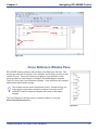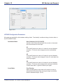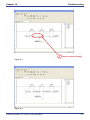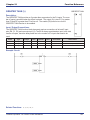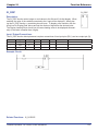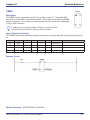
1
USER MANUAL
Release Version 4.00
For EZ LADDER V1.0.4.1
Standard Edition
EZ LADDER
TOOLKIT
© Divelbiss Corporation. 2004-2009
Table of Contents
Table of Contents
Chapter 1 - Getting Started....................................................................................5
How to Use this Manual............................................................................................................................ 6
Installing the EZ LADDER Toolkit............................................................................................................ 7
Activating the EZ LADDER Toolkit.......................................................................................................... 9
Installing Additional Copies of EZ LADDER Toolkit.............................................................................. 11
Chapter 2 - Navigating EZ LADDER Toolkit.........................................................12
EZ LADDER Toolkit Overview.................................................................................................................. 13
EZ LADDER Toolkit Menus...................................................................................................................... 14
EZ LADDER Toolkit Tool Bars and Tool Bar Buttons............................................................................ 18
Ladder Diagram Workspace.................................................................................................................... 20
Cross Reference Window Pane............................................................................................................... 21
Output Window Pane................................................................................................................................ 22
Chapter 2 - Ladder Diagram Basics......................................................................23
Relay Logic vs Ladder Diagram.............................................................................................................. 24
Basic Ladder Diagram Symbols.............................................................................................................. 25
Power Rails and Links.............................................................................................................................. 26
Connection Types..................................................................................................................................... 27
Understanding Ladder Diagram Functionality....................................................................................... 28
Chapter 4 - Configuring Targets............................................................................29
Understanding Targets............................................................................................................................. 30
The Project Settings Window.................................................................................................................. 30
Selecting the Hardware Target................................................................................................................ 33
Viewing Target Information...................................................................................................................... 34
Updating / Installing Target Kernels....................................................................................................... 35
Target Utilities........................................................................................................................................... 36
Chapter 5 - Creating Ladder Diagram Projects...................................................39
Creating Ladder Diagram Projects.......................................................................................................... 40
Understanding Objects & Variables........................................................................................................ 40
Creating and Placing Variables............................................................................................................... 42
Variable Types........................................................................................................................................... 43
Variable Attributes.................................................................................................................................... 44
Keeping Variable Values on Power Loss................................................................................................ 47
Placing Objects and Drawing Links........................................................................................................ 47
Using Copy and Paste.............................................................................................................................. 49
Inserting and Deleting Rungs.................................................................................................................. 50
Saving EZ LADDER Toolkit Projects....................................................................................................... 50
Verifying and Compiling Ladder Diagrams............................................................................................ 51
Bit Addressable Variables........................................................................................................................ 52
Divelbiss Corporation - EZ LADDER Toolkit User Manual
2
Table of Contents
Chapter 6 - Downloading and Running Projects.................................................54
Switching Modes in EZ LADDER Toolkit................................................................................................ 55
Monitor Mode Overview........................................................................................................................... 56
Connecting to a Target............................................................................................................................. 57
Connecting for the First Time to a New Target...................................................................................... 59
Downloading Ladder Diagram Projects to Targets................................................................................ 60
Real-Time Features................................................................................................................................... 60
Chapter 7 - Retentive Variables.............................................................................63
What is a Retentive Variable.................................................................................................................... 64
How to Make a Variable Retentive........................................................................................................... 64
Retentive Variable Limitations................................................................................................................. 65
Chapter 8 - Pulse Width Modulation.....................................................................66
What is Pulse Width Modulation............................................................................................................. 67
PWM Output Basics.................................................................................................................................. 67
Configuring PWM in Project Settings..................................................................................................... 68
Controlling PWM in the Ladder Diagram Project................................................................................... 69
Chapter 9 - LCD Display Support..........................................................................71
LCD Display Functionality....................................................................................................................... 72
Configuring the LCD Display in the Project Settings............................................................................ 72
Displaying Messages on the LCD Display............................................................................................. 74
Chapter 10 - Keypad Support................................................................................77
Keypad Functionality................................................................................................................................ 78
Configuring the Keypad in the Project Settings.................................................................................... 78
Getting Data from the Keypad................................................................................................................. 80
Chapter 11 - Serial Printing Support.....................................................................82
Serial Print Functionality.......................................................................................................................... 83
Configuring the Serial Print Feature....................................................................................................... 83
Printing Data to a Serial Device using a Serial Port.............................................................................. 85
Chapter 12 - J1939 Networking.............................................................................87
J1939 Communications............................................................................................................................ 88
Configuring J1939 Communications...................................................................................................... 88
Receiving J1939 Network Data................................................................................................................ 90
Chapter 13 - Modbus Networking.........................................................................91
Modbus Slave............................................................................................................................................ 92
Divelbiss Corporation - EZ LADDER Toolkit User Manual
3
Table of Contents
Chapter 14 - OptiCAN Networking........................................................................97
What is OptiCAN....................................................................................................................................... 98
Planning the OptiCAN Network............................................................................................................... 98
Hardware Requirements & Recommendations...................................................................................... 98
OptiCAN Specifications............................................................................................................................ 101
Using Controllers on the OptiCAN Network........................................................................................... 101
Using the OptiCAN Configuration Tool................................................................................................... 112
Chapter 15 - SPI Devices and Support.................................................................117
SPI Slave Support..................................................................................................................................... 118
SPI Bus Devices........................................................................................................................................ 124
Chapter 16 - SSI Encoder......................................................................................137
Synchronous Serial Interface (SSI) Encoder Input................................................................................ 138
Slave SSI Encoder Input.......................................................................................................................... 140
Chapter 17 - EZ LADDER Toolkit Reports............................................................141
EZ LADDER Toolkit Reports.................................................................................................................... 142
Chapter 18 - Troubleshooting................................................................................145
Error Messages......................................................................................................................................... 146
Common Ladder Diagram Errors............................................................................................................ 149
Chapter 19 - Analog Inputs....................................................................................151
Analog Input Overview............................................................................................................................. 152
Analog Input Installation / Configuration............................................................................................... 152
Using Analog Inputs in the Ladder Diagram Project............................................................................. 154
Averaging Analog Input Readings.......................................................................................................... 154
Scaling Analog Input Readings............................................................................................................... 155
Chapter 20 - Hardware Targets..............................................................................158
PLC on a ChipTM Integrated Circuits....................................................................................................... 160
PLC on a ChipTM Modules......................................................................................................................... 163
Enhanced Baby Bear PLC Models.......................................................................................................... 169
Harsh Environment PLC Models............................................................................................................. 176
PCS PLC Models....................................................................................................................................... 184
Solves-It! Plug in PLC Models................................................................................................................. 188
Chapter 21 - Function Reference..........................................................................192
Object and Function Block Basics.......................................................................................................... 194
Divelbiss Corporation - EZ LADDER Toolkit User Manual
4
CHAPTER 1
Getting Started
This chapter provides detailed information for getting started using the EZ LADDER Toolkit. Included in this section are installation instructions, activating EZ LADDER Toolkit and
instructions on how information in this manual is presented.
Chapter Contents
How to Use this Manual.............................................................................5
Installing the EZ LADDER Toolkit.............................................................6
Activating the EZ LADDER Toolkit............................................................8
Installing Additional Copies of EZ LADDER Toolkit................................10
Divelbiss Corporation - EZ LADDER Toolkit User Manual
5
Chapter 1
Getting Started
How to Use this Manual
In this manual, the following conventions are used to distinguish elements of text:
BOLD
Denotes labeling, commands, and literal portions of syntax that must appear exactly as shown.
Italic
small caps
Used for variables and placeholders that represent the type of text to be entered by the user.
Used to show key sequences or actual buttons, such as OK, where the user clicks the OK button.
In addition, the following symbols appear periodically appear in the left margin to call the readers attention to
specific details in the text:
Warns the reader of a potential danger or hazard that is associated with certain actions.
Appears when the text contains a tip that is especially helpful.
Indicates that the text contains information to which the reader should
pay particularly close attention.
This manual is divided into Chapters that are organized to promote a step by step progression of using the
EZ LADDER Toolkit from installation to troubleshooting. Each chapter contains specific information that is
relevant to understanding how to use the EZ LADDER Toolkit.
Divelbiss Corporation - EZ LADDER Toolkit User Manual
6
Chapter 1
Getting Started
Installing the EZ LADDER Toolkit
To install EZ LADDER Toolkit on your computer, follow the following steps. Once EZ LADDER Toolkit is
installed, it must be activated before it may be used with actual hardware targets.
Windows Administrator Rights are required for proper installation. The EZ LADDER directory
security is dependent on local / network security settings and may be set for user Read/Execute
only. To allow the user to be able to write to this directory, an Administrator must change the
permissions accordingly.
Windows Administrator Rights are required to install / register / activate EZ LADDER. Installing
EZ LADDER Toolkit without Administrator Permissions will cause EZ LADDER Toolkit not install
and not operate correctly.
1. Copy the Serial Number printed on the face of the
EZ LADDER Toolkit CD to a piece of paper. You will
need this serial number during installation.
2. Insert the EZ LADDER Toolkit CD into your CD
drive. If you have Active Content Enabled for your
CD Drive, a Menu will appear. Click the
install ez ladder standard edition v1.0.4.1 to run
the EZ LADDER Toolkit setup.
If this screen does not appear. Click the start button
and choose run. Browse to the CD Drive, the
EZ LADDER directory and then the V1.0.4.1 directory.
Select Setup.exe and click ok and ok to run the installer.
3. The EZ LADDER Toolkit Installation Wizard will open.
Click next.
Divelbiss Corporation - EZ LADDER Toolkit User Manual
7
Chapter 1
Getting Started
4. Complete the Name, Organization fields and
enter the Serial Number. Click next.
The serial number entered is used during
activation. If the serial number is not correct,
you will not be able to activate your
EZ LADDER Toolkit.
5. Use the default location for installing the EZ LADDER
Toolkit or browse and select a different location.
Click next.
6. All the information is gathered. Click next to
install the EZ LADDER Toolkit. The EZ LADDER
installer will copy all the required files and create a
shortcut.
7. When installation is complete, click finish.
Divelbiss Corporation - EZ LADDER Toolkit User Manual
8
Chapter 1
Getting Started
Activating the EZ LADDER Toolkit
Until EZ LADDER Toolkit is activated, it will only operated in DEMO mode which does not connecting
to actual hardware targets (controllers) or downloading programs.
Now that the EZ LADDER Toolkit is installed, it must be activated to enable all the features. You will need
the following to activate your EZ LADDER Toolkit.
1. An internet connection and web browser like Internet Explorer ( does not have to be the computer
that EZ LADDER is installed on).
2. Your EZ LADDER Toolkit CD Case. You will need your CID Code located on the back of the case.
3. EZ LADDER Toolkit installed.
Once activated, EZ LADDER Toolkit is fully functional and will operate with hardware targets. The process
of registering and activating is completing the on-line registration form receiving a counter key. This key must
be loaded into EZ LADDER Toolkit and when loaded, it will activate your copy of EZ LADDER Toolkit.
If EZ Ladder is not registered, it will prompt you to do so when the application is started.
To activate and register your EZ LADDER Toolkit, follow the installation wizard as follows:
1. When prompted to Activate EZ LADDER, click yes.
2. You must read and agree to the license agreement
to activate the EZ LADDER Toolkit. Click the I agree
box and click next.
Divelbiss Corporation - EZ LADDER Toolkit User Manual
9
Chapter 1
Getting Started
2. Click the link provided. A web browser window will
open to the registration and activation page on
Divelbiss.com.
You will need the Activation key provided by
EZ LADDER and your CID Code # located on the
back of your EZ LADDER Toolkit CD case.
If you do not have your CID Code #, you must
obtain it prior to continuing the activation.
Contact Divelbiss Customer Support.
If you close EZ LADDER prior to completing activation, the original Activation Key cannot be
used. A new Activation Key must be used to activate the EZ LADDER Toolkit.
3. Copy / Paste or type your Activation key into the
Activation key form box on the web site Activation and
Registration page, if not already pre-loaded (Internet
Explorer will preload this for you).
4. Complete all other form entries. All information must
be completed. The CID Code# is found on the
EZ LADDER Toolkit’s CD Case (located on back side).
5. Click the register & get key button. The Activation key
and other information will be confirmed and if valid,
a Counter Key, Username and Password will be
displayed. Save the Username and Password as
they can be used to download updates to EZ LADDER
Toolkit.
If the information is not valid, the registration will fail. Activation can fail due to an incorrect Serial
Number, incorrect CID Code# or if this serial number has been registered more times than
allowed per the license agreement (typically 2 times). Check this information. If you are still
unable to activate EZ LADDER Toolkit, Contact Divelbiss Customer Support.
6. Copy / Paste or type the Counter Key into the
Counter Key form box in the EZ LADDER Toolkit
Activation Window. Click proceed.
7. A Dialog box will appear verifying that EZ LADDER
has successfully been activated.
Divelbiss Corporation - EZ LADDER Toolkit User Manual
10
Chapter 1
Getting Started
Installing Additional Copies of EZ LADDER Toolkit
The EZ LADDER Toolkit license agreement allows the EZ LADDER Toolkit to be installed on up to two
computers (usually a PC and a laptop). To install on a second computer, install the EZ LADDER Toolkit and
Activate it as was done on the original computer.
If you attempt to activate a serial more than two time (unless you have purchased a site license),
the activation will fail as the serial number has been activated the maximum number of allowed
times.
If you are re-installing due to a hardware failure or moving computers, Contact Divelbiss
Customer Support to allow additional activations.
Divelbiss Corporation - EZ LADDER Toolkit User Manual
11
CHAPTER 2
Navigating EZ LADDER Toolkit
This chapter provides detailed information on the basics of navigating and using the EZ
LADDER Toolkit’s workspace, menus, tool bars and windows.
Chapter Contents
EZ LADDER Toolkit Overview...................................................................13
EZ LADDER Toolkit Menus........................................................................14
FILE MENU................................................................................................14
EDIT MENU................................................................................................15
VIEW MENU...............................................................................................16
PROJECT MENU.......................................................................................16
REPORTS MENU......................................................................................17
WINDOW MENU........................................................................................17
HELP MENU..............................................................................................18
EZ LADDER Toolkit Tool Bars and Tool Bar Buttons..............................18
Ladder Diagram Workspace......................................................................20
Cross Reference Window Pane.................................................................21
Output Window Pane.................................................................................22
Divelbiss Corporation - EZ LADDER Toolkit User Manual
12
Chapter 2
Navigating EZ LADDER Toolkit
EZ LADDER Toolkit Overview
When the EZ LADDER Toolkit is started, it will open in the Edit Mode. This mode is where ladder diagram
projects are created, functions are inserted and variables are placed. When actually downloading ladder
diagram projects to targets or monitoring ladder diagram operation on hardware targets, it is referred to as
Run Mode. The Run Mode is explained in Chapter 6.
Figure 2-1 identifies the components that are part of the Edit Mode.
1
2
4
5
3
6
Figure 2-1
1. Project Filename:
The name of the currently viewed project will be displayed in this
position.
2. Menus: Drop-down menus for programming features and options.
3. Cross Reference:
Quick Click Cross References for functions, objects and variables.
4. Tool Bars: Tool bars for placing functions, objects and drop-down function lists.
5. Ladder Workspace:
Area where the ladder diagram is drawn.
6. Output Window:
This is where status messages are displayed when Verifying or
Compiling ladder diagram programs.
Divelbiss Corporation - EZ LADDER Toolkit User Manual
13
Chapter 2
Navigating EZ LADDER Toolkit
EZ LADDER Toolkit Menus
The EZ LADDER Toolkit has many features and options. Basic commands, features and options are used
and controlled through drop down menus. Figure 2-2 shows the standard EZ LADDER Toolkit Menu bar. As
with any Windows based application, clicking on a menu heading will cause the drop down menu to open.
Figure 2-2
The menus found in the EZ LADDER Toolkit are: File, Edit, View, Project, Reports, Window and Help. Some
of these menus are specific to EZ LADDER Toolkit features while others are part of the basic Windows structure.
FILE MENU
The FILE Menu includes the standard windows functionality for file control and printing. The FILE Menu
items are: New, Open, Close, Save, Save As, Print, Print Preview, Print Setup and Exit. A recently opened
file list is also included for quick recall of recently opened ladder diagram projects.
New
Open
Close
Save
Save As
Print
Print Preview
The New menu item is used to create a new, blank EZ LADDER Toolkit Ladder Diagram Project.
The Open menu item is select and open a previously saved EZ LADDER Toolkit Ladder Diagram
Project.
The Close menu item closes the currently selected EZ LADDER Toolkit Ladder Diagram Project.
The Save menu item is used to save the currently selected EZ LADDER Toolkit Ladder Diagram
Project. If the project has not been saved previously, the Save As dialog is displayed.
The Save As menu item is used to save the currently selected EZ LADDER Toolkit Ladder Diagram
Project under a new name.
Opens the Print dialog box for printing the currently selected EZ LADDER Toolkit Ladder Diagram
Project with the settings defined in the Print Setup menu.
Opens a window to view the ladder diagram project as it is to be printed.
Divelbiss Corporation - EZ LADDER Toolkit User Manual
14
Chapter 2
Print Setup
Exit
Navigating EZ LADDER Toolkit
Opens a window to configure print and printer settings.
Closes all currently opened ladder diagram projects and closes the EZ LADDER Toolkit application
program.
EDIT MENU
The EDIT Menu includes the standard windows functionality for editing and editing preferences. The EDIT
Menu items are: Undo, Redo, Cut, Copy, Paste, Select All, Settings.
Undo
Redo
Cut
Copy
Paste
When pasting objects and rungs, enough space must be available at the pasting point for the
Windows clipboard contents. The paste will not complete unless sufficient space is provided (# of
rungs and space on each rung).
Select All
Settings
The Undo will cause the last action performed to be undone.
The Redo will cause an action that was undone using the Undo, to be repeated or completed again.
The Cut menu is disabled in the EZ LADDER Toolkit. To delete an object or multiple objects, select
the object(s) using the selector tool and remove by press the delete key.
The Copy is disabled in the EZ LADDER Toolkit. To copy an object or multiple objects, select
the object(s) using the selector tool, right click the mouse and select copy. This will copy all the
selected objects to the Windows clipboard.
The Paste menu item is disabled in the EZ LADDER Toolkit. To paste an object or multiple objects,
position the mouse at the starting point to paste, right click the mouse and select paste. This will
paste the Windows clipboard contents into the ladder diagram project.
The Select All menu item is disabled in the EZ LADDER Toolkit. The Settings menu item opens the LD (ladder diagram) settings window. This window allows general
setting to be configured such as displaying grid, fonts, etc. Typically, it is recommended to leave the
settings at the factory defaults.
Divelbiss Corporation - EZ LADDER Toolkit User Manual
15
Chapter 2
Navigating EZ LADDER Toolkit
VIEW MENU
The VIEW Menu is used to view currently selected target information and to view or hide tool bars and optional windows.
Target Information
Basic Components
Cross References
The Cross References menu item will cause the Cross Reference Window to be visible or hidden.
Edit Tools
Function List
Output
During the Compile process, it is important to have this window visible. Information including compile
status and errors are displayed here.
Toolbar
The target information window provides details of the selected hardware target (selected in the
Projects Settings menu) including target name, minimum kernel version required for this version of
EZ LADDER Toolkit, Supported Objects and Functions, Analog I/O and Digital I/O. The target
information may be printed using the provided print button.
The Basic Components menu item will cause the basic components tool bar to be visible or hidden.
This tool bar includes buttons for the direct contact, inverted contact, direct coil, inverted coil, CTU,
CTD, CTUD, TP, TON and TOF functions.
The Edit Tools menu item will cause the edit tools tool bar to be visible or hidden. This tool bar
includes buttons for select, horizontal link, vertical link, Edit Vars, Inst Vars, Verify, Compile (C),
MON and text boxes (Abc..).
The Function List menu item will cause the drop down function list to be visible or hidden. This tool
bar is used to select and insert functions into the ladder diagram project.
The Output menu item will cause the Output Window to be visible or hidden. This window displays
important messages during the Verify and Compile Operations.
The Toolbar menu item will cause the standard windows functions toolbar to be visible or hidden.
This tool bar includes, New, Open, Save, Cut, Print and more.
PROJECT MENU
The PROJECT Menu is used to view and configure Project target settings including hardware target selections, and installing and configuring optional target features.
Divelbiss Corporation - EZ LADDER Toolkit User Manual
16
Chapter 2
Settings
Bootloader
OptiCAN
Navigating EZ LADDER Toolkit
The Settings menu item opens the Project Settings Dialog. This dialog is used to configure the
actual hardware target (controller) and its features. The target is selected from the available list.
Depending upon the target selected, additional configuration settings may be required and additional
features can be configured from this menu. Refer to Chapter 4 for detailed information regarding
target configurations.
The Bootloader menu item will open the Bootloader dialog window. This window is used to install or
update hardware target kernels. The Bootloader menu item is only available in the Run Mode.
The OptiCAN menu item will open the OptiCAN Configuration Tool. This tool is used to configure the
OptiCAN network. The OptiCAN menu item is only available in the Run Mode and when OptiCAN is
enabled.
REPORTS MENU
The REPORTS Menu is used to generate, view and print reports that may be helpful when developing a ladder diagram project.
Variable Definitions
Cross References
The Variables Definitions report generates a list of all variables present in the ladder diagram project
and their specific information including name, I/O Number, Default Value and their description.
The Cross Reference opens the Cross Reference Dialog box. This box is where the criteria for
the report is selected. The following are the selectable criteria items: Input, Output, Internal,
Function, Unused Variables, Contacts Without Coils, Coils Without Contacts, Drum Sequencer
Tables, Retentive Variables and Network Address / Registers. After the required items are selected
or deselected, click ok. This generates the viewable and printable report.
WINDOW MENU
The WINDOW Menu is the basic Window’s menu for viewing and controlling open application windows. This
menu is typically found in every Window’s based program. Since this functionality is based on Windows, it
will not be described in detail.
Divelbiss Corporation - EZ LADDER Toolkit User Manual
17
Chapter 2
Navigating EZ LADDER Toolkit
HELP MENU
The HELP Menu is useful to determine software versions and registration information. Currently, there is no
active help built-in to the EZ LADDER Toolkit.
About
Splash Screen
Opens the EZ LADDER Toolkit about dialog box. The Toolkit version is displayed at the top of the dialog box. The File Versions tab identifies versions of each of the EZ LADDER Toolkit components. The License Information tab identifies the EZ LADDER Toolkit Serial Number and who it is registered to.
Opens the EZ LADDER Toolkit splash screen. This screen is normally viewable for a few seconds
when EZ LADDER Toolkit is started.
EZ LADDER Toolkit Tool Bars and Tool Bar Buttons
The EZ LADDER Toolkit provides tool bars for many common functions for ease of use and to increase
efficiency when programming ladder diagram projects. As discussed earlier, many of these tool bars may be
either viewed or hidden. EZ LADDER Toolkit defaults these tool bars as viewable.
Figure 2-3
Each tool bar contains multiple buttons. The following describes the function of each button.
New Project. Opens a new blank EZ LADDER Toolkit Project Window.
Open Project. Browse and open an existing EZ LADDER Toolkit Project.
Save Project. Saves the currently selected EZ LADDER Toolkit Project.
Cut. Cuts (Deletes) the selected Items.
Divelbiss Corporation - EZ LADDER Toolkit User Manual
18
Chapter 2
Navigating EZ LADDER Toolkit
Copy. Copies the currently selected items to the Window’s Clipboard.
Print Project. Opens the Print dialog for printing the EZ LADDER Toolkit Project.
Help. Opens the Help About dialog.
Select Tool. Selects individual or multiple items. Click on item to select or click and drag to
select multiple items.
Horizontal Link. Used to draw horizontal links between functions, object and variables.
Vertical Link. Used to draw vertical links between functions, object and variables.
Edit Variables. Opens the Edit Variables Dialog. Variables are created, edited and deleted
using this dialog box.
Insert Variables. Clicking in the ladder diagram workspace inserts a variable in that location.
The inserted variable is selected from a dialog box that opens.
Verify Program. Verifies the ladder diagram and elements are complete and do not break
any rules. This is automatically done when the compile button is clicked.
Compile Program. This does an automatic verify and then compiles the ladder diagram
project for the specific hardware target (controller).
Monitor Mode. This changes the EZ LADDER workspace from the Edit Mode to the Monitor
Mode. The Monitor Mode is where ladder diagram projects are downloaded to and
monitored on targets.
Insert Comment. This inserts a comment block into the ladder diagram project.
Direct Contact. This inserts a Direct Contact (Normally Open Contact) into the ladder
diagram project workspace wherever you click.
Negated Contact. This inserts a Negated Contact (Normally Closed Contact) into the ladder
diagram project workspace wherever you click.
Direct Coil. This inserts a Direct Coil (Normally Open Coil) into the ladder
diagram project workspace wherever you click. Can only be placed in last column.
Negated Coil. This inserts a Negated Coil (Normally Closed Coil) into the ladder
diagram project workspace wherever you click. Can only be placed in last column.
Divelbiss Corporation - EZ LADDER Toolkit User Manual
19
Chapter 2
Navigating EZ LADDER Toolkit
Count Up Function. This inserts a Up Counter Function into the ladder diagram project
workspace wherever you click.
Count Down Function. This inserts a Down Counter Function into the ladder diagram project
workspace wherever you click.
Count Up and Down Function. This inserts an Up and Down Counter Function into the
ladder diagram project workspace wherever you click.
Pulse Timer Function. This inserts an Pulse Timer Function into the ladder diagram project
workspace wherever you click.
On Timer Function. This inserts an ON Timer Function into the ladder diagram project
workspace wherever you click.
Off Timer Function. This inserts an OFF Timer Function into the ladder diagram project
workspace wherever you click.
This is used to insert any function (specifically those
functions that do not have a quick used tool bar
button. Select the function from the drop down menu and click the Insert Function button. This will
place the function into the ladder diagram project workspace wherever you click.
Ladder Diagram Workspace
The ladder diagram workspace is the area of the screen where objects and links are placed to create the
ladder diagram program. Most objects can be placed at any location in the workspace provided there is
actual space available. The DIRECT coil, Negated coil, LATCH coil and UNLATCH coil are the only objects
that must be placed in a particular location. They must be located in the last column (next to the right power
rail). Any attempt to place one of them in another location will cause an error dialog box to be displayed.
A ladder diagram is created using “rungs”. A rung is a horizontal line of logic. EZ LADDER Toolkit allows
the maximum number of rungs to be configured when the target is selected in the Project Settings dialog.
Figure 2-4 shows the ladder diagram workspace and rungs of horizontal logic.
Divelbiss Corporation - EZ LADDER Toolkit User Manual
20
Chapter 2
Navigating EZ LADDER Toolkit
ELEMENTS on RUNG 1
ELEMENTS on RUNG 2
Rung Numbers
Figure 2-4
Cross Reference Window Pane
EZ LADDER Toolkit provides a real-edit-time Cross Reference Window. This
window provides lists of contacts, coils, variables, and functions as well as their
location by rung. This quick reference provides an easy method to locate
where a contact or other function is located in the ladder diagram program.
Figure 2-5 shows the Cross Reference Window. Cross references are updated
automatically when objects change.
This window may be used to find objects quickly. Double-click on any
of the object rung numbers listed for an object or function and EZ
LADDER Toolkit will locate and display that section of the ladder
diagram.
The Cross Reference Window may be viewed or hidden by using the
View Cross References Menu.
Figure 2-5
Divelbiss Corporation - EZ LADDER Toolkit User Manual
21
Chapter 2
Navigating EZ LADDER Toolkit
Output Window Pane
EZ LADDER Toolkit provides an Output Window pane where error messages are displayed. Typically, error
messages are only updated and displayed during a Verify operation or Compile operation. Figure 2-6 displays an example error identified during a compile process.
When an error message identifies a location, (i.e.: “ERROR: Object Motor at: (9,1) doesn’t have a left link at (8,1)), the first number in the location refers to the column in the workspace while the second number refers to the actual rung number where the error occurs (Column, Rung).
Figure 2-6
Divelbiss Corporation - EZ LADDER Toolkit User Manual
22
CHAPTER 3
Ladder Diagram Basics
This chapter provides detailed information on understanding the origin of ladder diagrams
as they relate to original relay logic, basic ladder diagram symbols, power rails, links, types
of circuit connections and ladder diagram functionality.
Chapter Contents
Relay Logic vs Ladder Diagram................................................................24
Basic Ladder Diagram Symbols...............................................................25
Contacts....................................................................................................25
Coils...........................................................................................................25
Power Rails and Links...............................................................................26
Power Rails...............................................................................................26
Links..........................................................................................................26
Connection Types.......................................................................................27
Understanding Ladder Diagram Functionality........................................28
Divelbiss Corporation - EZ LADDER Toolkit User Manual
23
Chapter 3
Ladder Diagram Basics
Relay Logic vs Ladder Diagram
Prior to the invention of the Programmable Logic Controller (PLC), control panels consisted of large numbers of relays, motor starters and other devices, wired to create the required functionality. Today, with the
use of PLCs, the same functionality is achieved by drawing the circuit functionality in software; similar to the
original relay logic panel wiring diagrams were drawn.
Ladder Diagram is a graphical representation of boolean equations, using contacts (inputs) and coils (outputs). The ladder diagram language allows these features to be viewed in a graphical form by placing graphic symbols into the program workspace similar to a Relay Logic electrical diagram. Both ladder diagram and
relay logic diagrams are connected on the left and right sides to power rails.
A comparison of a hard-wired relay logic system and a programmable system using EZ LADDER Toolkit as
the programming platform will show the similarities which make the programming using EZ LADDER Toolkit
quick and easy to apply to any application.
Figure 3-1 shows a block diagram on the left and the hard-wired relay logic control system on the right.
easy comparison, it is divided into three sections.
For
Input Devices: Includes devices operated manually (i.e.: push buttons) and devices operated automatically
(i.e.: limit switches) by the process or machine being controlled.
Relay Control Logic: Consists of relays interconnected to energize or de-energize output devices in response to status of input devices, and in accordance with the logic designed into the control circuit.
Output Devices: Consists of motor starters, solenoids, etc. which would control the machine or process.
Figure 3-1
In place of hard-wired relay logic circuitry, EZ LADDER Toolkit applications are programmed using relay-type
symbology. This symbology brings ease and familiarity to the programming while adding flexibility. Figure
3-2 is the same circuit as shown in Figure 3-1 as it is programmed using the EZ LADDER Toolkit’s relay-type
symbology.
Figure 3-2
Divelbiss Corporation - EZ LADDER Toolkit User Manual
24
Chapter 3
Ladder Diagram Basics
Basic Ladder Diagram Symbols
In ladder diagram, all devices are represented by symbols (objects and function blocks). Chapter 21 provides detailed descriptions for all EZ LADDER Toolkit objects and function blocks. This section will give a
basic information regarding the most commonly used objects.
Contacts
Contacts represent two types of devices. The first is real world digital input (devices) such as limit switches,
push-button switches, and proximity sensors. The second is that contacts may represent internal relays;
also named control relays (CRs). When acting as a real world input, the ladder diagram object will represent the current state of the real world input it is assigned. When used as an internal control relay, the
contact will represent the current state of the control relay’s coil.
Contacts are represented in the EZ LADDER Toolkit by two different objects: Direct Coil and Negated Contact.
Contacts are always shown in their at-rest or un-powered state.
Direct Contact
Also known as a normally open contact, the direct contact may represent real world inputs or internal relay
contacts. As a real world input, when the input is energized (TRUE), it will be represented by a TRUE condition in the ladder diagram; causing power to flow through it to any following objects and function blocks. As
a real world input, when the input is de-energized (FALSE), it will be represented by a FALSE condition in
the ladder diagram; not allowing power to flow through it to any following objects and function blocks. When
used as an internal relay, the state of the contact (TRUE or FALSE) depends upon its internal coil state.
Negated Contact
Also known as a normally closed contact, the negated contact may represent real world inputs or internal
relay contacts. As a real world input, when the input is energized (TRUE), it will be represented by a FALSE
condition in the ladder diagram; not allowing power to flow through it to any following objects and function
blocks. As a real world input, when the input is de-energized (FALSE), it will be represented by a TRUE condition in the ladder diagram; causing power to flow through it to any following objects and function blocks.
When used as an internal relay, the state of the contact (TRUE or FALSE) depends upon its internal coil
state and is always opposite of the Direct Contact.
Coils
Coils represent two types of devices. The first is real world digital output (devices) such as solenoids, valves
and motors. The second is that coils may represent internal relays; also named control relays (CRs).
When acting as a real world output, the ladder diagram object will control the current state of the real world
output it is assigned. When used as an internal control relay, the coil will control the current state of the
control relay’s coil.
Divelbiss Corporation - EZ LADDER Toolkit User Manual
25
Chapter 3
Ladder Diagram Basics
Direct Coil
Also known as a normally open coil, the direct coil may represent real world outputs or internal relay coils.
As a real world output, when the coil is energized (TRUE), it will be cause the real world output to be TRUE
(energized). As a real world output, when the coil is de-energized (FALSE), it will cause the real world output to be FALSE (de-energized). When used as an internal relay, it controls it’s contact(s) state.
Negated Coil
Also known as a normally closed coil, the negated coil may represent real world outputs or internal relay
coils. As a real world output, when the coil is energized (TRUE), it will cause the real world output to be
FALSE (de-energized). As a real world output, when the coil is de-energized (FALSE), it will be cause the
real world output to be TRUE (energized). When used as an internal relay, it controls it’s contact(s) state
and is always opposite of the Direct Coil.
Power Rails and Links
Power Rails
As previously discussed, an EZ LADDER Toolkit ladder diagram contains objects (contacts, coils and function blocks). For the ladder diagram to operate correctly, each rung must be complete on each side by connecting it to the left power rail and the right power rail. This is required because all objects in a rung must
have a power source (the left power rail) to provide power to the objects and a common return (right power
rail) to complete the circuit.
Power rails run the entire length of an EZ LADDER Toolkit project. Figure 3-3 shows a typical ladder diagram rung and identifies the power rails. Please note, the rung is connected to both the right and left power
rails.
Left Power Rail
Right Power Rail
Figure 3-3
Links
As discussed previously, a rung must be complete and connected to both power rails for proper operation.
Links (Horizontal and Vertical) are used to connect objects and function blocks to other objects and function
blocks as well as to power rails. Horizontal Links connect devices horizontally or on the same rung. Vertical
Links connect devices on different rungs. Consider each link like an electrical wire that is needed to connect
devices in a circuit. Figure 3-4 identifies the types of links.
Divelbiss Corporation - EZ LADDER Toolkit User Manual
26
Chapter 3
Ladder Diagram Basics
Vertical Link
Horizontal Link
Figure 3-4
Connection Types
As seen in previous sections, the use of power rails, horizontal and vertical links creates a wide variety of
ways to draw ladder diagram circuits. Below are some typical connection types. They are created by using
horizontal and vertical links.
Simple Series Connection
Figure 3-5
Multiple Device Series Connection
Figure 3-6
Parallel Connection
Figure 3-7
Divelbiss Corporation - EZ LADDER Toolkit User Manual
27
Chapter 3
Ladder Diagram Basics
Complex Series / Parallel Connection
Figure 3-8
Understanding Ladder Diagram Functionality
When a ladder diagram is installed on a PLC or other controller, it will scan the program from top to bottom
and left to right. A scan is similar to reading a page. A page is read from top to bottom reading each line
left to right. One complete reading of the program is considered a scan. The larger the scan time (one
complete read cycle), the less often any real world I/O devices are monitored and controlled. Scan time is
an important consideration in the design of a ladder diagram. This scan time may be viewed in the Monitor
Mode when running a ladder diagram with a hardware target.
Figure 3-9 diagrams the functionality and order which a ladder diagram functions.
All real-world inputs are read
for their state (true/false)
All real-world outputs are set
to their new state (true/false)
Rung 1 is scanned from Left to
Right, Setting any internal
variables immediately
Each additional rung is
scanned left to right in order
and internal variables are set.
Figure 3-8
Divelbiss Corporation - EZ LADDER Toolkit User Manual
28
CHAPTER 4
Configuring Targets
This chapter provides basic information and steps required to identify, select and configure
hardware targets (actual hardware controllers or PLCs) in the EZ LADDER Toolkit.
Chapter Contents
Understanding Targets..............................................................................30
The Project Settings Window....................................................................30
Target Tab Settings..................................................................................31
Version Tab Settings................................................................................32
Options Tab Settings...............................................................................33
Selecting the Hardware Target..................................................................33
Viewing Target Information.......................................................................34
Updating / Installing Target Kernels........................................................35
Target Utilities.............................................................................................36
When Unable to Connect to the Target..................................................36
When Able to Connect to the Target.......................................................38
Divelbiss Corporation - EZ LADDER Toolkit User Manual
29
Chapter 4
Configuring Targets
Understanding Targets
Targets is the term used in the EZ LADDER Toolkit to describe the actual electronic hardware controller
or Programmable Logic Controller (PLC) to which the ladder diagram is specifically written to operate on.
Generally, most ladder diagrams can be utilized on different hardware targets with only minor changes to the
ladder diagram program itself.
Each hardware target is unique in that each usually have differing number of inputs, outputs, analog I/O and
other features. Due to the differences, in each EZ LADDER Toolkit ladder diagram project, the actual target
must be identified (selected) and it’s optional features (if any) installed and configured properly. Refer to
Chapter 20 - Hardware Targets for specific target details for each supported target.
It is important to understand that using PLC targets such as PCS Controllers, Harsh Environment Controllers, etc typically have minimal features that require additional configuration after the actual
hardware target is selected; while targets such as the PLC on a Chip require you to install and configure each and every I/O point, device and feature you intend to use.
Failure to correctly select, install or configure a feature in the Project Settings may result in the target
not operating as anticipated or features and functions not showing available for the target.
For a target to be able to use the compiled ladder diagram program created using the EZ LADDER Toolkit, it
must also have its kernel installed. The kernel is the hardware target’s basic operating system or bios. The
kernel is required before any programs can be installed. The kernels for targets are automatically installed
on your computer when the EZ LADDER Toolkit is installed. They are typically found in C:\Program Files\
Divelbiss\EZ Ladder\Kernel\.
Hardware targets ship from the factory without a kernel installed. The kernel must installed prior to
downloading the first ladder diagram program. The target is shipped without a kernel to provided
greater flexibility in version control.
The Project Settings Window
To create a ladder diagram project in EZ LADDER Toolkit, you must first select the hardware target. If you
attempt to place any ladder diagram objects in the workspace prior to selecting a target, the Project Settings
Window will open requiring you to select the target automatically. EZ LADDER Toolkit uses the target selection to filter and display only ladder diagram objects and functions supported by the selected target.
Only the actual hardware target that will be used should be selected. Selecting a different target will
allow the use of objects and function blocks that may not be supported by the actual hardware target as well as not allow use of objects and function blocks that are supported.
To select the target, either try to place a ladder diagram object in the workspace or use the Project Menu
and click Settings. The Project Settings Window / Dialog box will open. Figure 4-1 is an example of the
Project Settings Window and identifies the main components of it.
Divelbiss Corporation - EZ LADDER Toolkit User Manual
30
Chapter 4
Configuring Targets
1
5
6
3
2
4
Figure 4-1
Target Tab Settings
1. Project Setting Tabs:
Select the appropriate tab to configure target settings. Figure 4-1
represents the TARGET tab, Figure 4-2 represents the VERSION tab,
and Figure 4-3 represents the OPTIONS tab. Clicking on a tab selects
the tab for viewing.
2. Serial Settings:
Select the serial port on the computer that will be used to communicate
to the target. These settings are used to connect, download and
monitor ladder diagram programs running in EZ LADDER’s program
run and monitor mode.
The baud rate for all hardware targets is 57600. Setting this to a
different baud rate will result in no communications with between the
target and EZ LADDER Toolkit.
3. Target List:
This is a list of all targets supported by your version of EZ LADDER
Toolkit. Click on the target name to select.
When selecting some targets, an additional dialog may open. This
dialog is used to specifically select the target’s model number (i.e.:
selecting Enhanced Baby Bear will open a new dialog and allow
selection of the target by it’s model number : ICM-EBB-XXX).
Divelbiss Corporation - EZ LADDER Toolkit User Manual
31
Chapter 4
Configuring Targets
4. Code Type:
Configure the type of code to generate. At this time, this feature is not a user changeable item in EZ LADDER Toolkit.
5. Properties:
When a target has been selected, the properties button may appear
(target specific). If this button appears, clicking the properties will allow
additional configurations for the selected target. This button is only available on certain targets. Properties may include: J1939, PWM and OptiCAN.
6. Optional Buttons:
When certain targets are selected, like the properties button, other
buttons may appear. These additional buttons that are target specific
are used to configure items like Modbus Communications and more.
Version Tab Settings
The Version Tab will display the current build and version of the ladder diagram that is currently active in the
EZ LADDER Toolkit. The build and version information is useful when determining if a program version is
current. Figure 4-2 shows the Version settings tab of the Project Setting Window. Version setting may be
changed in this window, if required.
1. Version Number:
A version number for the ladder diagram may be entered here. This
number will not change automatically. It must be manually adjusted for each revision or release of the ladder diagram project.
2. Build Number:
The current build number is displayed here. Each time the ladder
diagram project is Compiled, the build number automatically
increments. This number may be over-written in this window if needed.
1
2
Figure 4-2
Divelbiss Corporation - EZ LADDER Toolkit User Manual
32
Chapter 4
Configuring Targets
Options Tab Settings
The Options Tab will display the currently selected options and preferences. Some of these options are target specific while others are standard. Figure 4-3 shows the Options settings dialog box.
1. Number of Rungs:
This is where the maximum number of rungs in the ladder diagram
is specified. The default number is 100 rungs.
Inserting or Deleting rungs in an EZ LADDER Toolkit ladder diagram project will change this number accordingly. This number should be considered a starting number of rungs. If the number of rungs is not sufficient for the program size, return to this dialog and adjust the
number of rungs. The number of rungs may be adjusted at any time.
1
Figure 4-3
Selecting the Hardware Target
As discussed in a previous section, using the dialogs, select the target from the list. If required, select the
actual model number, configure any features that you wish to use and click ok. Chapter 20 - Hardware
Targets includes additional information for each supported hardware target.
To save the target selection, you must save the ladder diagram project using the Save or Save As menu
items. Hardware Target Selections are for the currently open and active EZ LADDER Toolkit ladder diagram
project only. For each new project, you must repeat the hardware target selection and configuration process.
Divelbiss Corporation - EZ LADDER Toolkit User Manual
33
Chapter 4
Configuring Targets
Viewing Target Information
EZ LADDER Toolkit provides includes a built-in quick reference tool to identify what I/O, Analog and functions are supported by a target. The first step is selecting a hardware target as previously shown. To view
the target supported features, from the View menu, click Target Information. The Target Information window will open as shown in Figure 4-4.
This window identifies: the Target Name, Minimum Target Kernel Version that is needed for this version of
EZ LADDER Toolkit, Supported Objects and Function Blocks, Analog Inputs, Digital Inputs and Digital Outputs.
The Target Information is printable using the print button.
Figure 4-4
Divelbiss Corporation - EZ LADDER Toolkit User Manual
34
Chapter 4
Configuring Targets
Updating / Installing Target Kernels
As new targets, functions and features are added to the EZ LADDER Toolkit and new versions of EZ
LADDER Toolkit are developed and released, to take advantage of newer features, it will be
necessary to update the actual target’s kernel with newer version.
These same steps may be taken to install a kernel in a target that is new as all new targets from the
factory do not have kernels installed.
EZ LADDER Toolkit provides an easy way to update the kernel on the hardware target.
1. Obtain the new kernel for the target (provided by Divelbiss via CD, e-mail or download).
2. Start EZ LADDER Toolkit and open any project that uses the target or create a new project with
the actual hardware target selected. This project must have at least one rung of ladder.
3. Verify the Serial Port Settings and connect the target to the computer.
4. Enter the Monitor Mode.
5. From the Project menu, select Bootloader.
6. EZ LADDER will connect to the target and the Bootloader dialog will open showing the current
version of the target’s kernel (if any). It will also display the target’s bootloader version.
See Figure 4-5.
Figure 4-5
Divelbiss Corporation - EZ LADDER Toolkit User Manual
35
Chapter 4
Configuring Targets
6. Click the erase user program button to erase the ladder diagram project on the target (if any). This is recommended before updating the kernel. (This applies to Bootloader versions 1.0.0.5
and later.) If this is a new blank target, this step is not necessary.
7. Click browse and select the kernel file for the hardware target. The dialog will update showing the
selected kernel file version in the Upload File section of the Bootloader dialog box.
8. To update or install the new kernel, click update target. A status box will appear indicating the
status of the kernel installation. During this, the new kernel is being installed. This may take
several minutes.
When updating or installing a kernel, DO NOT REMOVE the CABLE or the POWER. If
interrupted during this process, the target will be corrupted and return to a bootloader mode.
You must repeat all the above steps again.
Only the correct target’s kernel may be installed into a target. The target is checked against
the kernel automatically and will display an error if the wrong kernel is selected and an update
is attempted. If a wrong kernel is somehow loaded, contact Divelbiss Technical Support for
help regarding removing incorrect kernels.
Target Utilities
EZ LADDER Toolkit provides additional target utilities that may be used to correct actual target problems.
Although rare, occasionally, targets get corrupted and communications cannot be established using normal
methods. This can be caused by not erasing a ladder diagram prior to upgrading kernels, wrong kernels
installed and interruptions during kernel installations.
The Target Utilities listed here are only available on hardware targets that have V1.0.0.5 or later
bootloader versions installed. The bootloader is installed at the factory and can not be updated
outside the factory environment.
When Unable to Connect to the Target
The following steps may be taken if you can verify the connection problems is with the actual hardware target unit specifically (another unit connects with the same setup and program).
1. Start EZ LADDER Toolkit and open any project that uses the target or create a new project with
the actual hardware target selected. This project must have at least one rung of ladder.
3. Verify the Serial Port Settings and connect the target to the computer.
4. Enter the Monitor Mode.
Divelbiss Corporation - EZ LADDER Toolkit User Manual
36
Chapter 4
Configuring Targets
5. Press the F11 key on your computer’s keyboard. The dialog box in Figure 4-6 will open.
Figure 4-6
6. Disconnect power from the hardware target.
8. Apply power to the hardware target. If the time has elapsed, repeat steps 6-8 again.
The hardware target will now allow bootloader operations (other buttons are now active).
9. Choose the correct option to try and resolve your target issue.
7. Click the enter bootloader button in the dialog box. A timing dialog box will appear. This is
amount of time that is remaining to re-apply power to the hardware target.
Bootloader:
Bootloader will open the bootloader dialog box for updating kernels.
Erase LD Program: Erases the ladder diagram project from the hardware target’s memory. In the event the program is hanging and preventing a normal
connection, this will erase the program to allow a normal connect.
Restart Target:
Causes the hardware target to reboot. This is required when all other
bootloader actions have been completed. Without the restart, the
kernel will still not connect normally.
Using the Restart Target is the same as resetting the power to the
hardware target. Both will cause the target to restart and operate
normally.
Close:
Closes the dialog box.
Divelbiss Corporation - EZ LADDER Toolkit User Manual
37
Chapter 4
Configuring Targets
When Able to Connect to the Target
If you can connect normally to the target, there are only a few additional utilities available in the EZ LADDER
Toolkit.
1. If the target is connected to normally, press the F11 key on your computer’s keyboard. The
Device Properties dialog box will appear as in Figure 4-7.
Figure 4-7
If the actual hardware target does not support a Real Time Clock, then an error dialog box may
appear if you were successfully, connected to the hardware target prior to press the F11
button. Click ok to continue.
From this dialog, you can compare the actual computer time and date to the current time and date set on the
hardware target. If you wish to synchronize the time (set the hardware target to the computer time), click the
sync w/ pc button. The times should now be synchronized.
The ladder diagram project can be erased from this dialog by pressing the erase user program button.
Use caution when deleting the ladder diagram project from the target. There is no Undo. To reload
the hardware target, the original ladder diagram project must be opened, compiled and reloaded to
the target.
Divelbiss Corporation - EZ LADDER Toolkit User Manual
38
CHAPTER 5
Creating Ladder Diagram Projects
This chapter provides basic information and understanding to create ladder diagram
projects using EZ LADDER Toolkit including variables, variable types, inserting variables,
inserting objects and functions, bit addressable variables, drawing links, inserting and
deleting rungs, saving ladder diagram projects and verifying and compiling ladder diagram
projects.
Chapter Contents
Creating Ladder Diagram Projects...........................................................40
Understanding Objects & Variables.........................................................40
Creating and Placing Variables.................................................................42
Variable Types.............................................................................................43
Variable Attributes......................................................................................44
Keeping Variable Values on Power Loss.................................................47
Placing Objects and Drawing Links.........................................................47
Using Copy and Paste...............................................................................49
Inserting and Deleting Rungs....................................................................50
Saving EZ LADDER Toolkit Projects........................................................50
Verifying and Compiling Ladder Diagrams..............................................51
Bit Addressable Variables.........................................................................52
Divelbiss Corporation - EZ LADDER Toolkit User Manual
39
Chapter 5
Creating Ladder Diagram Projects
Creating Ladder Diagram Projects
When EZ LADDER Toolkit is opened, it will automatically create a new blank project and it’s corresponding
workspace as shown in Figure 5-1. A new project may be created at any time by choosing New from the
File menu.
Figure 5-1
Before adding any objects, functions or variables to the new workspace, the Target must be selected and
configured according to the target needs and your program requirements. Select your target by choosing
Settings from the Project menu. See Chapter 4 - Configuring Targets and Chapter 20 - Hardware
Targets for details.
When configuring your target, it is recommended to only install and configure features that are
intended to be used. Installing unused features degrades performance.
Understanding Objects & Variables
Ladder diagram projects in EZ LADDER Toolkit are comprised of a combination of objects, function blocks,
variables and links. It is important to understand the basic relation of these items. These items will be covered first generally, then in more detail as this chapter progresses.
Divelbiss Corporation - EZ LADDER Toolkit User Manual
40
Chapter 5
Creating Ladder Diagram Projects
Nearly all ladder diagram objects and function blocks rely on variables, either as a definition for the object or
addition to the function block to provide required data to function properly. A variable is a placeholder that
represents values that can change. A variable can represent any number depending upon its type.
Variables are an important part of understanding how EZ LADDER uses functions and objects. Some objects, such as Direct Contacts or Direct Coils are actually defined as variables themselves while other function blocks such as TON will require variables created, inserted and connected, using links, to the function
block itself to provide set points and other functional requirements.
Variables in the EZ LADDER Toolkit are global, meaning that each variable must be uniquely named
and can be changed or used anywhere in the ladder diagram project.
Using function blocks, variables can pass data (copy or move) to other variables, functions and objects.
Figure 5-2 illustrates a simple ladder diagram project that contains objects that are variables and inserted
variables linked to function blocks.
Direct Contact is
actual variable
named MotorStart
ElapTime is actual
variable inserted
and linked to the
function block
TON1.
Figure 5-2
Figure 5-2 identifies the two typical ways variables are used in an EZ LADDER Toolkit ladder diagram project. As shown, the On-Delay timer function block identified as TON1 uses two unique variables (one for the
set point - PT and one for the elapsed time - ET). All contacts and coils are actually variables themselves
and as they are created, they must be either assigned to an existing variable or a new variable created must
be created (declared) for them.
Divelbiss Corporation - EZ LADDER Toolkit User Manual
41
Chapter 5
Creating Ladder Diagram Projects
Creating and Placing Variables
Placing and creating variables can be done several ways. Inserting some objects automatically require the
selection or creation of a new variable when being inserted (forces a dialog box), while function blocks typically require you to insert any needed variables and link them without being prompted to do so.
We will identify how to create and assign variables using two methods, although variable creation is basically the same for all methods.
Placing Contacts and Coil Type Objects
To place a contact, from the tool bar, select the Direct Contact and locate a point in the workspace to place
the item. Clicking that location will place the object. When placing certain objects (coils and contacts), a
Contact Properties dialog box will appear. You can choose a variable that already exists from the dropdown list or type in a new name. For this example, we will type in a new name and click ok. If you had
selected a name that already exists, the object placement would be completed. Since we have chosen a
new variable, the dialog in Figure 5-3 will appear.
Figure 5-3
Click yes to create the new variable. The Add Variable dialog box will open automatically with the variable
name you entered already in the Name field. See Figure 5-4. For now click ok to create the variable. We
will cover the details of variable attributes later in this chapter. You have now successfully created a contact with a new variable. Repeat the same as needed for new contacts or coils.
Figure 5-4
Divelbiss Corporation - EZ LADDER Toolkit User Manual
42
Chapter 5
Creating Ladder Diagram Projects
Placing a Linked Variable
To place a variable that is linked to a function block, from the tool bar, select the Insert Variables button (Inst
Vars). In the ladder diagram workspace, click in an open area and the Variables window will open. This
window contains tabs at the top for all variable types supported.
When inserting a variable next to a function block input, only the variable types supported by the
function block will be displayed as tabs in the Variables window.
Select the appropriate type for the variable you are needing to insert and click the add button. The Add Variable dialog box will open automatically. Enter a variable name in the Name field. See Figure 5-4. For now
click ok to create the variable. We will cover the details of variable attributes later in this chapter. You have
now placed a linkable variable.
If the variable you need to insert already exists, select it from the list and click ok to insert it.
Variables names must always begin with a letter and cannot contain spaces. Trying to begin
variables with numbers or using spaces will result in a error message being displayed.
Variables may be created at any time without inserting or placing them in the ladder diagram
workspace. To create a variable without placing it, from the tool bar, select the Edit Variables button
(Edit Vars). The Variables window will open as shown previously. Use the add button to create
variables as needed.
When function blocks are used with variables, as previously covered, only supported variable types
are allowed. Typically, most function blocks will lock the types of variables linked to it’s outputs as
the same type linked to it’s inputs. When changing variable types that are an input or an output to a
function block, delete the variables and function block. Then insert the function block and new
variables to remove all the variable type associations that previously existed.
Variable Types
There are four variable types supported in the EZ LADDER Toolkit. They are: Boolean (BOOL), REAL,
INTEGER and TIMER. Each type of variable exists for specific purposes and each has pros and cons depending upon the ladder diagram project needs.
Examples of Variables:
Boolean:
0 or 1, False or True, Off or On
Real:
234.56, 192.345
Integer:
1, 525, 1034
Timer:
Days, Hours, Minutes, Seconds, Milliseconds
Divelbiss Corporation - EZ LADDER Toolkit User Manual
43
Chapter 5
Creating Ladder Diagram Projects
Boolean Variables
Boolean variables are based on only being in one of two states, typically either true or false (1 or 0, On or
Off). Boolean variables are most commonly used for contacts and coils, but also may be used with function
blocks as individual bits.
Real Variables
Real variables are based on numbers that use floating point math (use decimal points). Real variables can
range from -1.7x1038 to 1.7x1038. Real variables are typically used for calculations and with functions where
decimal point accuracy is required. Real variables used with function blocks result in a slower Scan Time.
Integer Variables
Integer variables are based on whole numbers (no decimal points) Integers can be ranged from
-2147483647 to 214483647. Integers are used when decimal points are not required. Integer result in a
faster Scan Time than real variables.
Timer Variables
Timer variables are used in conjunction with timer function blocks to provide input set points and output
elapsed time. Timer variables consist of milliseconds, seconds, minutes, hours and days.
Variable Attributes
For each variable type, specific attributes will apply. For most variables, these attributes are common.
While some attributes are optional such as description, others are required prior to creating the variable.
When creating a new variable, it is ideal to set it’s attributes with as much detail as possible.
Integer, Real and Boolean Variable Attributes
When adding new integer, real or boolean variables, refer to Figure 5-5 for the Add Variable dialog box. The
following are fields (attributes) for variables. Some must be completed while others are optional.
1. Name:
The variable name is entered in this field. This name will be used to
identify this variable and will be the name viewed in the workspace and any
cross reference and reports. All names must begin with a letter and cannot
contain any spaces. A unique name is require for each variable.
Divelbiss Corporation - EZ LADDER Toolkit User Manual
44
Chapter 5
2. Description:
3. Variable Type:
Creating Ladder Diagram Projects
This is where a text based description may be entered for more clarification
and details regarding this variable. Descriptions appear in reports and in
many dialog boxes. This attribute is optional.
The variable type is selected in this box. The choices are:
Input:
Select Input if the variable will actually represent a real world digital input on the target. Selecting this option will require that physical address of the input to be entered in the Var I/O Number field.
Output: Select Output if the variable will actually represent a real world digital output on the target. Selecting this option will require that physical address of the output to be entered in the Var I/O Number field.
Internal: Select Internal if the variable has no real world
connection but is to be used internal in the ladder
diagram project only.
Retentive:
This check box is used to identify retentive variables
(variables that will store their current value on power
loss and reload it automatically when power is restored).
This feature must be supported on the hardware target.
4. Var I/O Number: This is where the physical address of real world I/O points is entered. This
field is only used if the Variable Type is either Input or Output. 5. Default Value:
This is where default variable values are set. An internal variable will be
equal to this value unless it has been altered by the ladder diagram. This is
used to preset values in the ladder diagram for comparisons as well as other
uses. This field is optional.
6. Address Register: When the ladder diagram project is configured to use register based
communications such as Modbus or OptiCAN, the register assignment for the
variable is configured in this field. If left blank, there is no assigned register.
This field only appears if a feature that will use a register is installed or
supported on the hardware target and Projects Settings. This field is optional.
Clicking the edit button opens an additional dialog box with all the available
networks and makes assigning registers easier.
Divelbiss Corporation - EZ LADDER Toolkit User Manual
45
Chapter 5
Creating Ladder Diagram Projects
1
2
4
5
3
6
Figure 5-5
Timer Variable Attributes
When adding new timer variables, refer to Figure 5-6 for the Add Variable dialog box. The following are
fields (attributes) for timer variables. Some must be completed while others are optional. Typically, time
durations are entered as the unit of measure closes to the set point.
Larger times may be entered into fields provided that the total timer value does not exceed 24 days.
For example, 1000 ms may be entered and will be considered 1 second when the program executes.
However, if 750 hours is entered, the time is greater than 24 days and the timer will malfunction.
1. Name:
The variable name is entered in this field. This name will be used to
identify this variable and will be the name viewed in the workspace and any
cross reference and reports. All names must begin with a letter and cannot
contain any spaces. A unique name is require for each variable.
2. Description:
This is where a text based description may be entered for more clarification
and details regarding this variable. Descriptions appear in reports and in
many dialog boxes. This attribute is optional.
3. Days:
The time duration in number of days.
4. Hours:
The time duration in hours.
5. Minutes:
The time duration is minutes.
6. Seconds:
The time duration in seconds.
7. Milliseconds
The time duration in milliseconds. The millisecond resolution is target specific
and is shown in parenthesis.
Divelbiss Corporation - EZ LADDER Toolkit User Manual
46
Chapter 5
Creating Ladder Diagram Projects
8. Retentive:
This check box is used to identify retentive variables (variables that will store
their current value on power loss and reload it automatically when power is
restored). This feature must be supported on the hardware target.
1
8
2
3
4
5
6
7
Figure 5-6
Keeping Variable Values on Power Loss
In the event of a power loss to the target, EZ LADDER Toolkit is designed to allow ladder diagram variables
to be stored and then be reloaded when power is restored. This is called the Retentive feature and variables
must be configured as retentive as well as the hardware target must support this feature. See Chapter 7 Retentive Variables for more details on the retentive feature.
Placing Objects and Drawing Links
To place an object in an EZ LADDER Toolkit project, select the object or function block from the tool bar or
select the object or function block from the tool bar drop down menu. Position the pointer in the ladder diagram workspace where the object is to be inserted and left-click. This places the object at that point. As you
add objects, variables may need created. See earlier in this chapter for how to create variables.
Figure 5-7 illustrates the placement of a Direct Contact and Direct Coil. Please refer to Chapter 21 - Function Reference.
The last placed object stays selected until a different object or button in the tool bar is chosen. This
feature allows an object be placed multiple times without the need of re-selecting the object.
Divelbiss Corporation - EZ LADDER Toolkit User Manual
47
Chapter 5
Creating Ladder Diagram Projects
To place an object or function, there must be enough space in the ladder diagram workspace at the
point of insertion. If there is insufficient space, an error message will display.
Placed Direct Contact
Placed Direct Coil
Figure 5-7
Refer to Figure 5-7, note when placing objects near the left or right power rails, links are
automatically drawn to the power rails. This also applies when variables are inserted next to
functions; the links are automatically drawn from the inserted variable to the function.
To finish the circuit shown in Figure 5-7, it will be necessary to draw a horizontal link between the contact
and coil on rung 1. Select the Horizontal Link Tool from the tool bar. Refer to Chapter 2 - Navigating EZ
LADDER Toolkit for details on tool bars and buttons.
To draw the link, click and hold the click at the location where the link will start, at the right side of the contact
on rung 1. Holding the mouse button down (clicked), drag the pointer to the left side of the coil on rung 1.
When the link is drawn connecting both objects, release the mouse button to complete the link.
If a vertical links are required (as in parallel circuits), select the Vertical Link Tool from the tool bar. Using the
same method, click and drag until a vertical link is created.
Horizontal and Vertical links snap to grid locations and can only be started and stopped at one of these locations. Take care when connecting links to objects and function blocks that the link actually connects to the block and not just near it. If a link does not connect, then an error will occur when Verifying or Compiling the ladder diagram project. Figure 5-8 shows a connected link and a link that
is not connected.
Divelbiss Corporation - EZ LADDER Toolkit User Manual
48
Chapter 5
Creating Ladder Diagram Projects
Bad Link
Good
Connected
Links
Figure 5-8
When connecting two function blocks in series, where a variable output of the first needs to be
connected to the second function blocks variable input, you must insert a variable between them. Failure to place a variable between function blocks (variable inputs and outputs only) will result in
the ladder diagram project Compiling successfully, but it will not operate as intended.
Using Copy and Paste
EZ LADDER Toolkit, being a Windows based application, allows the copy and paste functions inherit to
Windows with certain limitations imposed. It is possible to copy any single or combination of objects, function
blocks, variables and links to the Windows Clipboard.
To Copy object(s), choose the Select Tool from the tool bar. To choose a single object, left click on the object
to select it. To select multiple objects, click and drag across the objects. Objects may be selected by holding the ctrl key while clicking on them. With the items selected, using the Edit Menu, choose Copy or
right-click and choose Copy. The objects are now copies to the Windows Clipboard.
Divelbiss Corporation - EZ LADDER Toolkit User Manual
49
Chapter 5
Creating Ladder Diagram Projects
Unlike a standard windows application, objects on the clipboard cannot be pasted using ctrl-v or by using
the Edit Menu’s Paste feature. To paste an object or multiple objects in EZ LADDER Toolkit, use the Select
Tool from the tool bar and hover the point at the location to paste (if pasting multiple objects, this would be
the top, left of the objects that will be pasted). Right-click and choose Paste. The objects will be pasted.
When pasting objects or rungs, there must be enough room to paste the copied section (horizontally
and vertically) or an error will occur. When pasting rungs, move the pointer near the left power rail
as an pasting point.
Inserting and Deleting Rungs
During development of a ladder diagram project, it often becomes necessary to insert new rungs between
existing rungs or to delete rungs that will not be required.
Inserting Rungs
To insert a new rung in EZ LADDER Toolkit, position the pointer where the insertion needs to occur (typically
near the left power rail). Right-click and choose Insert Rung. A rung will insert at this location. All later
rungs will be moved accordingly and all cross references will update with the new rung numbers.
Deleting Rungs
To delete a rung, position the pointer on the rung to be deleted. Right-click and choose Delete Rung. The
selected rung will be deleted. Only empty rungs may be deleted.
Saving EZ LADDER Toolkit Projects
Saving an open ladder diagram project can be done two ways. Click the Save button on the tool bar or use
the File Menu, and choose Save. If the project has not been previously saved, a dialog box will appear to
enter name and save the project. The Save As selection in the File Menu always provides a dialog box for
naming the project.
Divelbiss Corporation - EZ LADDER Toolkit User Manual
50
Chapter 5
Creating Ladder Diagram Projects
Verifying and Compiling Ladder Diagrams
After a ladder diagram has been created, it must be verified and compiled prior to downloading it to an actual hardware target. This process checks the ladder diagram for adherence to all EZ LADDER Toolkit and
target rules and then creates a file that will be downloaded to the hardware target. This file, while maintaining the functionality of the ladder diagram actually has no graphical representation and is generally not
recognizable or viewable.
To Verify a Project
The verification process will check the ladder diagram for completeness and common rules, verifying there
are not broken links, etc. To verify the ladder diagram project, on the tool bar, click the Verify button. In the
Output Window at the bottom, a message will be displayed with the status and results of the verification
process.
To Compile a Project
The compilation process involves two actions. The first is an automatic verification is done and if no problems are detected, the ladder diagram is then compiled (converted into machine language code for downloading to the hardware target). To compile a ladder diagram project, on the tool bar, click the Compile
button.
All EZ LADDER Toolkit Projects must be compiled prior to downloading them to a hardware target.
Once a program has been compiled, it does not need to be compiled again unless the actual ladder
diagram project has changed since it was last compiled.
Any errors encountered during the compilation process must be corrected before the compilation will successfully complete and provide operational compiled code. See Chapter 18 - Troubleshooting for common
error messages. Figure 5-9 illustrates two Output Window messages for the same ladder diagram project.
The first identifies errors during the compile process while the second illustrates a successful compile.
Figure 5-9
Divelbiss Corporation - EZ LADDER Toolkit User Manual
51
Chapter 5
Creating Ladder Diagram Projects
Bit Addressable Variables
As covered earlier in this chapter, variables are an important part of an EZ LADDER Toolkit project. While
most projects will use variables as described earlier, the EZ LADDER Toolkit also provides a feature to use
integer variables and then actually control the individual bits that make up the entire integer variable (number, total of 32 bits per integer). This feature is called Bit Addressable Variables.
Any integer may be used as a bit addressable variable. As a bit addressable variable, each variable has
32 individual bits that are numbered 0-31 and each bit represents the binary bit of the total integer variable
number. To understand bit addressable variables, you must have a basic understanding of the binary numbering system where numbers are created using ones and zeros in specific placeholder bits that represent
an actual number.
Bit Number (0-31): 6
Placeholder:
5 4 3 2 1 0
64 32 16 8 4 2 1
Add the placeholder numbers of bits with 1’s only
8 + 4 + 1 = 13
Binary Bits:
0 0
0 1 1 0 1
The integer variable value would be 13.
Setting the bit of a Variable
To set the bit of an integer variable, identify or create the variable. In addition to the variable that will be bit
addressable (the one you just identified), additional variables will be required to write to the bits of the original bit addressable variable (one for each bit that you intend to use).
These additional variables will be (boolean) output variables, representing a boolean 0 or 1 for the actual bit.
In Figure 5-10, the Add Variable dialog box shows the creation of one of the actual bit controlling boolean
variables. These bit controlling variables are always set as Output and the Var I/O Number is the variable
name of the bit addressable variable and the bit number to control separated by a period. In Figure 5-10,
the bit addressable variable is named Limit and the bit shown being controlled is 3 or the placeholder for the
number 8 in integer form and the variable that is controlling the bit is named Bit3. Therefore, if Bit3 is true
then bit 3 of the variable Limit would be true, changing the value of the variable Limit by its placeholder value
(in this case 8).
Bit Controlling Output
Variable (Boolean) Name
Name of the Bit Addressable
variable and bit number to be
controlled. Format is:
Name.BitNumber
Variable Type: Output
Figure 5-10
Divelbiss Corporation - EZ LADDER Toolkit User Manual
52
Chapter 5
Creating Ladder Diagram Projects
Reading the bit of a Variable
To read the bit of an integer variable, identify or create the variable. In addition to the variable that will be bit
addressable (the one you just identified), additional variables will be required to read to the bits of the original bit addressable variable (one for each bit that you intend to use).
These additional variables will be (boolean) input variables, representing a boolean 0 or 1 for the actual
bit. In Figure 5-11, the Add Variable dialog box shows the creation of one of the actual bit reading boolean
variables. These bit reading variables are always set as Input and the Var I/O Number is the variable name
of the bit addressable variable and the bit number to read separated by a period. In Figure 5-11, the bit
addressable variable is named Limit and the bit shown being read is 3 or the placeholder for the number 8
in integer form and the variable that is reading and storing the bit is named RBit3. Therefore RBit3 will be
equal to the actual binary status (0 or 1) of bit 3 of the Limit variable.
Bit Reading Input Variable
(Boolean) Name
Name of the Bit Addressable
variable and bit number to be
read. Format is:
Name.BitNumber
Variable Type: Input
Figure 5-11
Divelbiss Corporation - EZ LADDER Toolkit User Manual
53
CHAPTER 6
Downloading and Running Projects
This chapter provides basic information needed to connect to hardware targets, download
ladder diagram projects and use real-time EZ LADDER Toolkit features.
Chapter Contents
Switching Modes in EZ LADDER Toolkit..................................................55
Monitor Mode Overview.............................................................................56
Connecting to a Target...............................................................................57
Connecting for the First Time to a New Target........................................59
Downloading Ladder Diagram Projects to Targets.................................60
Real-Time Features....................................................................................60
Divelbiss Corporation - EZ LADDER Toolkit User Manual
54
Chapter 6
Downloading & Running Projects
Switching Modes in EZ LADDER Toolkit
EZ LADDER Toolkit is generally has two modes of operation. Up to this point, most of the time we have
been using the Edit Mode. The Edit Mode is used to open and close projects, configure targets, create ladder diagram projects, verify and compile them. The Monitor Mode is used to connect to hardware targets,
download ladder diagram projects, monitor their power flow in real-time and to work with target utilities.
Typically switching modes is done often during ladder diagram project development.
Switching to Monitor Mode
To switch to monitor mode, on the tool bar, click the Monitor button. Refer to Chapter 2 - Navigation EZ
LADDER Toolkit for tool bar and buttons. EZ LADDER Toolkit will switch from the Edit Mode to the Monitor Mode. While the ladder diagram workspace will appear similar, some tool bars and buttons will change
adding functionality for features only needed in Monitor Mode. Figure 6-1 shows EZ LADDER Toolkit in the
Monitor Mode.
Figure 6-1
In addition to the tool bar changes, the Output Window is not available in the Monitor Mode as the
program should be compiled in the Edit Mode prior to switching to the Monitor Mode.
Divelbiss Corporation - EZ LADDER Toolkit User Manual
55
Chapter 6
Downloading & Running Projects
Switching to Edit Mode
When in the Monitor Mode, to switch back to the Edit Mode, on the tool bar, click the Edit button. EZ LADDER Toolkit will switch from Monitor Mode to the Edit Mode. All Edit Modes standard tool bars, menus and
windows will reappear.
Monitor Mode Overview
While the Monitor Mode generally looks similar to the Edit Mode, the tool bars, menus and windows can differ greatly. Refer to Figure 6-2 for identification status fields. Project Version
Tool Bar
Project Name
Estimated Scan Time
Project Build #
Figure 6-2
Divelbiss Corporation - EZ LADDER Toolkit User Manual
56
Chapter 6
Downloading & Running Projects
The following descriptions are for buttons found on the Monitor Mode Tool Bar.
Edit Mode. Switches EZ LADDER Toolkit to the Edit Mode.
Connect. Connects EZ LADDER Toolkit to the hardware target’s Programming Port.
Disconnect. Disconnects EZ LADDER Toolkit from the hardware target..
`
Download. Transfers the compiled ladder diagram project to the hardware target and saves
the program in memory and starts executing the program. The program will remain until over
written by a new downloaded program.
Stop. Stops execution of the ladder diagram project on the hardware target.
Go. Starts execution of the ladder diagram project on the hardware target.
Target Information. Opens the a target information dialog that identifies the actual target
version connected to EZ LADDER Toolkit and the current Target’s Name or Model Number.
EEPROM Erase. This erases the EEPROM on the hardware target. The target must support
EEPROM storage for this feature to function.
There is no UNDO when erasing the EEPROM. Once the EEPROM has been
erased, all contents are lost. Take care in erasing the EEPROM as to not lose
valuable data.
Connecting to a Target
To download a ladder diagram project to a hardware target, it must first be connected to in the Monitor
Mode. To successfully connect to a target, the Serial Port Settings in the Project Settings Window must
match our computers setup, the appropriate programming cable must be connected from the computer’s serial port to the hardware target’s programming port and the hardware target must be turned on.
To connect to target, click the Connect button located on the tool bar. If an error occurs, check the Serial
Port Settings, cable and target. Also see Chapter 18 - Troubleshooting.
Divelbiss Corporation - EZ LADDER Toolkit User Manual
57
Chapter 6
Downloading & Running Projects
When connecting to a target, additional dialog boxes may appear depending on if a ladder diagram
project is currently loaded on the target, if the name matches the currently open project’s name and if
the build number has changed.
When Target has no Project Loaded
If the target does not have a previously loaded ladder diagram project, then no dialog boxes will open when
the Connect button is clicked. The Status window typically will change to Waiting to identify that the connection is complete and the hardware target is waiting for a ladder diagram project to be downloaded. Figure
6-3 illustrates the status as described.
Figure 6-3
When Target has Different Project Loaded
If the ladder diagram project name of the project open in EZ LADDER Toolkit does not match the name of
the ladder diagram project that is loaded on the target, the warning dialog in Figure 6-4 is displayed. Click
ok to clear this warning. This warning can be caused because the projects differ or the project open in EZ
LADDER Toolkit was renamed or saved with a different name using the Save As since it was loaded on the
target.
Figure 6-4
When Target has the Same Project
If the ladder diagram project name of the project open in EZ LADDER Toolkit does match the name of the
ladder diagram project that is loaded on the target, two results can occur. If the build number (that automatic
number that increments each time a project is compiled, See Chapter 4 - Configuring Targets), is the
same as the build number of the project loaded on the target, no dialog boxes are displayed. The Status,
Program Name, Program Version, Build Number and Scan Time are updated. Now ladder diagram project
can be viewed in real-time.
If the two build numbers differ, then the warning dialog box in Figure 6-5 is displayed. This dialog serves
as a warning that the two build numbers do not match. While this is usually caused by the ladder diagram
project being compiled again since it was downloaded, it also requires that you must download the new build
of the ladder diagram project to view it in real-time.
Divelbiss Corporation - EZ LADDER Toolkit User Manual
58
Chapter 6
Downloading & Running Projects
Figure 6-5
Connecting for the First Time to a New Target
To connect to a target, the target must have a kernel installed. As hardware targets are shipped from the
factory without kernels, the kernel must be loaded prior to being able to connect and download projects.
When trying to connect to a new target for the first time (if it is configured correctly and successful), the Bootloader Window automatically is displayed. From this window, the kernel can be selected and installed on the
hardware target. Figure 6-6 illustrates the Bootloader window. Refer to Chapter 4 - Configuring Targets
for details on installing and upgrading the hardware target kernel.
Figure 6-6
Divelbiss Corporation - EZ LADDER Toolkit User Manual
59
Chapter 6
Downloading & Running Projects
Downloading Ladder Diagram Projects to Targets
When connected to a hardware target, click the Download button located on the tool bar. A dialog box will
temporarily be displayed showing the status of the ladder diagram’s download to the target and the Status
field will indicate Downloading.
Upon completion of the download, the Status field will update and indicate Running. The target has now
been programmed with the ladder diagram project. A download action causes the project to download, for
the project to be saved in the target’s non-volatile memory and then it is given a execute command to begin
running on the target.
The project is now executing on the hardware target. The status of contacts, coils, function blocks, variables
and power flow may be viewed in real-time.
Disconnecting from the target or changing to Edit Mode does not stop the target from operating as it
can only be stopped by removing power or the use of the Stop button in the Monitor Mode.
It is important that all ladder diagram projects be archived for safe keeping. There is no method to recover a ladder diagram project from the target. The actual ladder diagram file must be available for editing and future downloads.
Real-Time Features
When connected to a hardware target with an executing program, there are additional real-time monitoring
features available in the EZ LADDER Toolkit. These features include Power Flow indication, Scan Time,
Starting and Stopping program execution, hover boxes and the ability to change variable values.
Power Flow Indication
Monitoring a project in real-time provides the ability to watch the state of contacts, coils, function blocks and
variables. See Figure 6-7. Contacts and Coils are actually represented in their current state (On / Off) by
color. Blue represents the contact or coil in it’s rest state (un-powered state) while Red represents a powered or flow condition. As real world and internal objects change during program execution, they are represented in color accordingly and the flow of power can be viewed (Power Flow) from the left power rail to the
right power rail).
Although contacts and coils change colors based on their actual state, some links may change
color, but most links and all function blocks remain the standard black and white color.
Divelbiss Corporation - EZ LADDER Toolkit User Manual
60
Chapter 6
Downloading & Running Projects
Red Indicates
Power Flow
Blue Indicates
No Power Flow
Figure 6-7
Scan Time
Scan time is calculated in real-time, updated and displayed in the Scan Time Field. The scan time is always
represented in milliseconds. The scan time resolution is target specific. For more information on scan time,
please see Chapter 3 - Ladder Diagram Basics.
Starting and Stopping Program Execution
The program on the target can be stopped and started again using the EZ LADDER Toolkit when in Monitor
Mode and connected to the target.
To Stop a program from executing on the target, on the tool bar, click the Stop button. This can be
useful when troubleshooting and diagnosing ladder diagrams that do not operate as expected.
To Start a program executing on the target, on the tool bar, click the Go button. This can be
useful when troubleshooting and diagnosing ladder diagrams that do not operate as expected.
Divelbiss Corporation - EZ LADDER Toolkit User Manual
61
Chapter 6
Downloading & Running Projects
Hover Boxes
Another useful feature that can be utilized in real-time monitoring is the use of hover boxes. When the
mouse pointer is hovered over an object, a hover box will appear that provides additional information in regards to the function or object including it’s name and current status. Figure 6-8 shows a typical hover box.
The mouse pointer is located over the contact CR2. Notice the hover box is now shown and identifies the
contact by name, type and it’s current state or value.
Figure 6-8
Changing Variable Values
EZ LADDER Toolkit provides an option for changing the value of a variable while the ladder project is executing. Double-click on the object and an dialog box appears with the current state or variable value. This
box is changeable and the value may be changed. Change the value as needed and click ok. The changes
take place immediately. The change does not affect the actual ladder diagram (in the Edit mode), only the
executing program. This is helpful for adjusting timer and counter values in real time during debugging.
Changing a contact variable (boolean) does not always have the desired effect. For example: If the
value of an internal coil (that is connected to a real world input) is changed using the dialog box, the
actual value will change only until the next scan and then will revert to its real world status. Since all
I/O status is re-evaluated each scan, the contacts and coils are updated and will override variable
changes. Actual real world inputs cannot be changed at all.
Changing any variable value in real-time does not change the ladder diagram project. Changes that
wish to be kept must be manually changed in the project in the Edit Mode. Additionally, any variable
changes on the target are lost if the target is stopped, started or power is reset to it.
Divelbiss Corporation - EZ LADDER Toolkit User Manual
62
CHAPTER 7
Retentive Variables
This chapter provides basic information to understand what Retentive variables are, when
to use and how to use them including their limitations.
Chapter Contents
What is a Retentive Variable......................................................................64
How to Make a Variable Retentive............................................................64
Retentive Variable Limitations..................................................................65
Divelbiss Corporation - EZ LADDER Toolkit User Manual
63
Chapter 7
Retentive Variables
What is a Retentive Variable
A Retentive variable is a variable that’s value is automatically stored in non-volatile memory in the event of a
power interruption on the hardware target. When power is restored, retentive variable values are automatically read from the non-volatile memory and re-loaded into their original variable.
Retentive variables are used often to recover from a power interruption and continue the process that is being controlled without initializing the process or wasting materials.
The hardware target must support Retentive Variables for this feature to work. Adding retentive variables to a ladder diagram project alone does not guarantee retentive functionality.
How to Make a Variable Retentive
For a variable to be retentive, it must be identified as retentive. To identify a variable as retentive in the Edit
Mode, click the Edit Vars button located on the tool bar. Select the variable that is to be retentive. Click the
edit button. The Edit Variable dialog will appear as in Figure 7-1.
Check box to
make variable
retentive
Figure 7-1
To make the variable retentive, click the Retentive check box and click ok. The variable is now retentive and
will be stored in the event of a power interruption provided the actual target supports the retentive feature.
The same check box is present when creating a new variable.
Divelbiss Corporation - EZ LADDER Toolkit User Manual
64
Chapter 7
Retentive Variables
Retentive Variable Limitations
While retentive variables and functionality can be a useful tool when creating ladder diagram projects. There
are limitations to when retentive variable usage.
As was discussed previously, retentive variables are stored in non-volatile memory (memory that retains
data without power) and that retentive variable functionality is target dependent. The actual target must have
non-volatile memory capability and the capability to detect a loss of power before power drops below the operating range for the target. In other words, the target must be able to sense the loss of power early enough
to provide the time needed to write the retentive variables to the non-volatile memory while the target’s input
power is still sufficient for proper operation. This functionality is programmed at the factory level and cannot
be altered in the ladder diagram project.
If designing a PLC on a ChipTM based custom product using the PLC on a ChipTM Integrated Circuit or
Module, this functionality is based on the use of the /LOW_VOLTAGE input (Integrated Circuit Pin:
56, Module: P1, Pin 12). This must be used with a loss of power circuit to detect the loss of power.
The maximum amount of memory for retentive variables is 100 bytes total. During programming,
you must take into consideration how many variables are retentive and how much memory they use.
Real and Integer variables require 4 bytes each while boolean variables require 2 bytes each.
Divelbiss Corporation - EZ LADDER Toolkit User Manual
65
CHAPTER 8
Pulse Width Modulation
This chapter provides basic information to understand what Pulse Width Modulation is and
how it is used as feature in the EZ LADDER Toolkit and hardware target.
Chapter Contents
What is Pulse Width Modulation...............................................................67
PWM Output Basics...................................................................................67
Configuring PWM in Project Settings.......................................................68
Controlling PWM in the Ladder Diagram Project....................................69
Divelbiss Corporation - EZ LADDER Toolkit User Manual
66
Chapter 8
Pulse Width Modulation
What is Pulse Width Modulation
Pulse Width Modulation, also referred to as PWM is a term common to the industrial controls and electronics
industries. Essentially PWM is generally an output that can be controlled in such a manner that will cause a
device connected to have varying operation. Consider a light dimmer, changing the knob changes the light
intensity; this is how a PWM output can affect a load such as a light.
PWM does what it’s name implies. By turning a PWM output on at a fast rate, the load device will appear
to be on all the time even though it is actually being turned on and off quickly. The rate at which the PWM
output is turned on and off is called the frequency. As the frequency changes (faster or slower), the result on
the load device changes like the light example from bright to dim. The PWM outputs a square-wave and the
time on vs the time off is the duty cycle. Figure 8-1 illustrates an example PWM output waveform.
Frequency 1
50% Duty Cycle
Freq.
2 50%
Duty
Cycle
Freq.
3 75%
Duty
Cycle
PWM OUTPUT
CHANNEL
Figure 8-1
PWM Output Basics
Pulse Width Modulation (PWM) Outputs are easy implement and utilize using the EZ LADDER Toolkit. PWM
channels may be selected and configured with 8 bit or 16 bit resolution. When configured as 8 bit resolution,
up to 8 total channels are supported. When configured as 16 bit resolution, up to 4 channels are supported.
PWM functionality, supported types and number of channels is always target dependent. While EZ
LADDER Toolkit provides the basic programmability, the hardware target must support PWM and the
selected configuration for the PWM outputs to operate correctly.
PWM output frequency is dependent upon the actual hardware target and the resolution configured.
Changing the resolution (or hardware target) will change the acceptable range of the PWM outputs.
Divelbiss Corporation - EZ LADDER Toolkit User Manual
67
Chapter 8
Pulse Width Modulation
Configuring PWM in Project Settings
As with most EZ LADDER Toolkit hardware supported features, the PWM channels and functionality must
installed and configured before it may be used in a ladder diagram project. The PWM channels are configured using the Project Settings. Using the Project Menu, choose Settings. The Project Settings window
will open as previously covered in Chapter 4 - Configuring Targets.
Select the target and click the properties button. Look in the target’s Properties window for a pwm properties
button. Click the pwm properties button to open the PWM Properties window as shown in Figure 8-2 .
2
3
1
4
5
6
Figure 8-2
The keystrokes and / or buttons used may differ slightly to gain access to the PWM settings, the PWM Properties Window is always identical without regard to the target selected.
The following describes the sections and functions for the PWM Properties window. Refer to Figure 8-2 for
item identification.
1. 8 or 16 bit Resolution:
The first choice should be selecting if 8 bits or 16 bits of PWM
resolution are required for the application. Select the appropriate
resolution. 8 bit resolution supports up to 8 total channels while 16 bit
resolution supports up to 4 total channels (the number of channels and
features are always target dependent).
Divelbiss Corporation - EZ LADDER Toolkit User Manual
68
Chapter 8
Pulse Width Modulation
2. Add Button:
The add button opens a select dialog that allows the selection and
installation of the PWM channels. To select multiple channels, hold the
ctrl key when selecting them. Only target supported channels will be
displayed. Channels are also limited by PWM resolution.
3. Remove Button:
Highlighting a channel and clicking the remove button, EZ LADDER
Toolkit will remove the PWM channel.
4. Max / Min Frequency:
As all PWM outputs are target specific, each may have different PWM
specifications. When a channel is installed and highlighted, these
fields will display the limitations of the actual target.
The Max and Min frequency can change based on the PWM
resolution selected.
5. Desired Frequency:
The desired frequency for the PWM channel is entered here. Not all
frequencies are attainable based on the target.
6. Actual Frequency:
The actual attainable frequency (closest to the desired frequency) is
shown. This frequency will be used.
Due to PWM frequency stepping limitations, not all frequencies are attainable, therefore a desired
frequency is entered and the actual frequency that will be used (closest match) is displayed.
Dependent upon which channels are installed, either CLK A or CLK B frequencies must be entered.
CLK A and CLK B operate identical except for which channels they control.
Once all the channels have been installed and configured, click ok to close the PWM Properties window.
The PWM is now configured and ready to be used in the ladder diagram.
Controlling PWM in the Ladder Diagram Project
With PWM channels configured in the Project Settings, it is simple to control the actual PWM channels in the
ladder diagram project.
Enabling a PWM Channel
To control a PWM output, specifically when it is enabled, disabled and it’s duty cycle, the PWM function
block is used. This function block has two inputs (EN for Enable and DC for Duty Cycle) and also has one
output (Q). When the PWM function block is enabled (the EN input is true), the PWM channel is active and
operating at the frequency defined in the project settings and the Duty Cycle (variable connected to DC of
the PWM function block). When the EN input is false, the PWM channel output is disabled. Figure 8-3 illustrates the PWM function block in a sample circuit.
Divelbiss Corporation - EZ LADDER Toolkit User Manual
69
Chapter 8
Pulse Width Modulation
When placing the PWM function block, a new dialog is opened to select the PWM channel and the
polarity of the PWM Channel.
Controlling the PWM Channel Duty Cycle
The PWM output’s duty cycle is controlled the PWM function block for that channel. Changing the value
of the variable connected to the DC input of the PWM function block immediately changes the duty cycle
accordingly. This gives a PWM output the ability to change duty cycle in real-time in response to control
parameter changes.
Figure 8-3
Changing the PWM Frequency
In addition to an adjustable duty cycle, the PWM clock frequencies (CLK A / CLK B) can be changed in the
ladder diagram project by use of the PWM_FREQ function block. The PWM_FREQ function block has two
inputs (EN for enable and F for frequency) and one output (Q). When the EN is true, the PWM channel
frequency is changed to the value of the variable connected to the F input of the function block. Figure 8-4
illustrates a sample circuit using PWM_FREQ.
When using the PWM_FREQ to change the frequency, the actual CLK A or CLK B frequency is
changed. This affects all channels that use that specific CLK signal. For example, if PWM channel
0 uses CLK A and PWM channel 2 uses CLK A, then adjusting the frequency using PWM_FREQ to
CLK A affects all the PWM channels that use CLK A, in this case 0 and 2 respectively.
When placing the PWM_FREQ function block, a new dialog is opened to select the PWM channel
Clock.
The PWM clock frequency will be equal to the value of the F input of the PWM_FREQ function block, thus
allowing real-time frequency changes.
Figure 8-4
Divelbiss Corporation - EZ LADDER Toolkit User Manual
70
CHAPTER 9
LCD Display Support
This chapter provides basic information to understand how to install, configure and use an
LCD Display with the EZ LADDER Toolkit
Chapter Contents
LCD Display Functionality.........................................................................72
Configuring the LCD Display in the Project Settings..............................72
Displaying Messages on the LCD Display...............................................74
Divelbiss Corporation - EZ LADDER Toolkit User Manual
71
Chapter 9
LCD Display Support
LCD Display Functionality
EZ LADDER Toolkit provides the ability to display text and variables using it’s built-in LCD support. EZ
LADDER Toolkit supports three different LCD (Liquid Crystal Display) displays. Using one of these displays
and the EZ LADDER Toolkit function blocks, messages may be displayed, variables displayed and in conjunction with the keypad feature, menus may be created.
LCD support is based on actual hardware target specifications. PLC on a ChipTM Integrated Circuits
and Modules support LCD display functionality. For PLCs and controllers, refer to the supported
features. See Chapter 20 - Hardware Targets.
These are the three LCD displays currently supported: 2x20 (2 Row, 20 Column), 2x40 (2 Row, 40 Column)
and 4x20 (4 Row, 20 Column). All supported displays use the HD44780 standard. EZ LADDER Toolkit supports only one LCD display in a ladder diagram project.
Configuring the LCD Display in the Project Settings
To be able to use an LCD display in an EZ LADDER Toolkit ladder diagram project, the LCD display must
first be installed and configured. As the PLC on a ChipTM is the most commonly used target for LCD displays, it will be used as an example to install and configure an LCD display.
The LCD display is configured using the Project Settings. Using the Project Menu, choose Settings. The
Project Settings window will open as previously covered in Chapter 4 - Configuring Targets.
Select the PLC on a Chip target and click the properties button. The target’s Properties window will open.
From the drop-down menu (DCPN), select the PLCHIP-M2-25620. Click the add button. The Device Properties window will open.
All the available devices and features for the target are shown in the Devices section. Scroll down and find
LCD. Figure 9-1 shows the Device Properties window.
Figure 9-1
Divelbiss Corporation - EZ LADDER Toolkit User Manual
72
Chapter 9
LCD Display Support
Click LCD and click ok. The Device Properties window will close and the previous target properties window
will now list the LCD as an installed device. Click the LCD in the device list. A properties button will appear
to the right. Refer to Figure 9-2.
Figure 9-2
Click the properties button. The Lcd Properties dialog box will open. In this dialog box, select the LCD port
on which the LCD will be physically connected (LCD_A, LCD_B or LCD_C). Please refer to the schematic
of your PLC on a ChipTM design for the correct port. See to Figure 9-3.
Enter the number of LCD display rows (1-4) and the number of LCD columns (8-40). Click ok to close the
Lcd Port dialog box. See Figure 9-3. The display is now configured and the current settings must be saved.
Figure 9-3
Divelbiss Corporation - EZ LADDER Toolkit User Manual
73
Chapter 9
LCD Display Support
Click ok close the Target’s properties and click ok again to close the Project Settings window. Use the File
Menu and Save the ladder diagram project. The LCD display can now be utilized from the ladder diagram
project.
Displaying Messages on the LCD Display
With the LCD display configured in the ladder diagram project, it is now possible to use the EZ LADDER
Toolkit’s function blocks to display messages and variables. Two basic function blocks that are used control
the display are: LCD_CLEAR and LCD_PRINT.
Clearing the Display
To clear the LCD display (blank all rows and columns), the LCD_CLEAR function block is used. The LCD_
CLEAR will clear the display when it senses a rising edge on it’s enable input (EN). Figure 9-4 shows an
example program using the LCD_CLEAR function block.
Figure 9-4
Writing to the Display
To write messages to the LCD Display, the LCD_PRINT function block is used. Using the LCD_PRINT function block is a two step process. When placing the function block, a new Lcd Print Properties dialog box will
open. See Figure 9-5. The Text field is where the message is typed that will be displayed. The Row field
is the row of the display where the text will be displayed. The Column field is the column where the text will
begin displaying.
Figure 9-5
Divelbiss Corporation - EZ LADDER Toolkit User Manual
74
Chapter 9
LCD Display Support
The first row and first column are always zero (0) and are limited by the actual hardware target display size. If text in a row is more than can be displayed on the LCD, it will be truncated. It does not automatically wrap to the next line. Each row of the display must be written to individually with separate LCD_PRINT function blocks.
When all the information is entered, clicking ok will cause the function block to be placed in the ladder diagram project. Figure 9-6 is a sample of a complete LCD_PRINT circuit.
Figure 9-6
Writing Variables to the Display
In addition to printing static text, it is often desirable to be able to print variables to the display. This is helpful
in displaying process parameters and menu items. To write a variable to the LCD display, the same LCD_
PRINT function block is still used. As in the simple text printing, the text is entered into the Text field. In addition to the text, control characters may be inserted that represent variables and how to format the variable
text. For a full listing of what control characters and formatting is supported, please see the LCD_PRINT
function block in Chapter 21 - Function Reference. Figure 9-7 illustrates a sample text dialog with control
characters.
Figure 9-7
When an LCD_PRINT function is inserted to display variables, a new variable input is added to the
function block automatically for each variable that will be displayed.
Divelbiss Corporation - EZ LADDER Toolkit User Manual
75
Chapter 9
LCD Display Support
Figure 9-8 represents a sample ladder diagram project using a LCD_PRINT function block with a variable
input that will be displayed.
Figure 9-8
The LCD_PRINT function block is rising edge sensitive. Therefore, it will only display one time as the ENable input goes high. The text will appear normally, but the variable will not appear to update or change as the ladder diagram is executing.
To overcome the rising edge issue when displaying variable, create TON timer circuit as shown in
Figure 9-10 and use the timer contact to act as a refresh for the ENable input on the LCD_PRINT
function block. The refresh timer should be adjusted to your display preferences. in Figure 9-10,
CR1 will toggle on and off based on the Timer function TON, giving the result of the LCD_PRINT
seeing a rising edge at that timing rate.
Figure 9-9
For more detail on all EZ LADDER Toolkit Function Blocks and objects, refer to Chapter 21 Function Reference.
Divelbiss Corporation - EZ LADDER Toolkit User Manual
76
CHAPTER 10
Keypad Support
This chapter provides basic information to understand how to install, configure and use the
Keypad feature in the EZ LADDER Toolkit.
Chapter Contents
Keypad Functionality.................................................................................78
Configuring the Keypad in the Project Settings......................................78
Getting Data from the Keypad...................................................................80
Divelbiss Corporation - EZ LADDER Toolkit User Manual
77
Chapter 10
Keypad Support
Keypad Functionality
EZ LADDER Toolkit provides the ability for the addition of keypad functionality. EZ LADDER Toolkit supports
a basic 4 row, 6 column keypad matrix. This keypad matrix includes the numbers 0-9, Enter, Clear, Up,
Down, +/-, Decimal Point, and F1-F4 (programmable function keys). Using this keypad matrix and the builtin EZ LADDER functions, menus and user interactions may be programmed into a ladder diagram project.
Keypad support is based on actual hardware target specifications. PLC on a ChipTM Integrated
Circuits and Modules support Keypad functionality. For PLCs and controllers, refer to the supported
features. See Chapter 20 - Hardware Targets.
Configuring the Keypad in the Project Settings
To be able to use an keypad in an EZ LADDER Toolkit ladder diagram project, the keypad must first be
installed and configured. As the PLC on a ChipTM is the most commonly used target for keypads, it will be
used as an example to install and configure an keypad matrix.
The keypad is configured using the Project Settings. Using the Project Menu, choose Settings. The Project Settings window will open as previously covered in Chapter 4 - Configuring Targets.
Select the PLC on a Chip target and click the properties button. The target’s Properties window will open.
From the drop-down menu (DCPN), select the PLCHIP-M2-25620. Click the add button. The Device Properties window will open.
All the available devices and features for the target are shown in the Devices section. Scroll down and find
Keypad. Figure 10-1 shows the Device Properties window.
Figure 10-1
Click Keypad and click ok. The Device Properties window will close and the previous target properties window will now list the Keypad as an installed device. Click the Keypad in the device list. A properties button
will appear to the right. Refer to Figure 10-2.
Divelbiss Corporation - EZ LADDER Toolkit User Manual
78
Chapter 10
Keypad Support
Figure 10-2
Click the properties button. The Keypad Properties dialog box will open. In this dialog box, select the
Keypad port on which the Keypad will be physically connected (KEYPAD_A, KEYPAD_B or KEYPAD_C).
Please refer to the schematic of your PLC on a ChipTM design for the correct port. See to Figure 10-3.
Figure 10-3
Click ok close the Target’s properties and click ok again to close the Project Settings window. Use the File
Menu and Save the ladder diagram project. The keypad matrix can now be utilized from the ladder diagram
project.
Divelbiss Corporation - EZ LADDER Toolkit User Manual
79
Chapter 10
Keypad Support
Getting Data from the Keypad
With the keypad configured in the ladder diagram project, it is now possible to use the EZ LADDER Toolkit’s
function blocks and objects to input user data and set points. The keypad can be read using two methods.
The two methods are: Integer and Real Variable entry using the Keypad Function block and the second is
identifying discrete key presses using contacts.
Real and Integer Inputs using the Keypad Function Block
To read data (integer or real) from the keypad, the Keypad function block is used. Select the keypad function
block from the drop-down menu and place it in the ladder diagram at the desired location. The Keypad block
will be inserted into the ladder diagram.
Each keypad function block has three inputs and three outputs. As with all function blocks, the EN (enable)
will enable the keypad function block or disable it. The MI and MA inputs are used to identify Minimum and
Maximum allowed entries respectively. The Q Output is true when the function is enabled. The KB output
will maintain the contents of the keypad buffer while KO is the actual value that was entered on the keypad
(and enter pressed). Figure 10-4 represents a typical keypad function in a ladder diagram project.
The Keypad function block can be used to input real or integer variables. When connecting a
variable, the type connected will limit all number inputs and outputs to the selected type (all integer
or all real).
Figure 10-4
Reading Discrete Key Presses using Contacts
Before being able to read any key presses using the Discrete key method, the ladder diagram must
have at least one Keypad Function Block installed and in use. Any discrete keys will not operate
unless one Keypad Function Block is installed in the ladder diagram project.
Divelbiss Corporation - EZ LADDER Toolkit User Manual
80
Chapter 10
Keypad Support
In addition to reading complete values from the keypad, it is possible to read individual keys to determine if
they are pressed. Each key has a predefined address that can be used as an input (boolean type variable
that is classified as an input). Create a contact as a new variable, and in the Var I/O Number field, enter the
address of the specific key desired. When the key is pressed, the contact will be true.
The following addresses are used to read discrete keypad buttons.
I/O Assignment
Button Description
I/O Assignment
Button Description
Numeric 0
Numeric 1
Numeric 2
Numeric 3
Numeric 4
Numeric 5
Numeric 6
Numeric 7
Numeric 8
Numeric 9
KB_CLEAR
KB_DP
KB_+ -
KB_F1
KB_F2
KB_F3
KB_F4
KB_UP
KB_DOWN
KB_ENTER
Clear Button
Decimal Point Button
+ / - Button
F1 Button
F2 Button
F3 Button
F4 Button
Up Button
Down Button
Enter Button
KB_0
KB_1
KB_2
KB_3
KB_4
KB_5
KB_6
KB_7
KB_8
KB_9
For more detail on all EZ LADDER Toolkit Function Blocks and objects, refer to Chapter 21 Function Reference.
Divelbiss Corporation - EZ LADDER Toolkit User Manual
81
CHAPTER 11
Serial Printing Support
This chapter provides basic information to understand how to install, configure and use the
Serial Printing feature in the EZ LADDER Toolkit.
Chapter Contents
Serial Print Functionality...........................................................................83
Configuring the Serial Print Feature.........................................................83
Printing Data to a Serial Device using a Serial Port................................85
Divelbiss Corporation - EZ LADDER Toolkit User Manual
82
Chapter 11
Serial Printing Support
Serial Print Functionality
EZ LADDER Toolkit provides the ability to serially print text and variables to other devices using a serial port.
This feature can be useful to send data to data loggers, displays and other devices. The serial print feature utilizes a standard serial port that may be configured as RS232, RS422 or RS485 and can operate with
multiple baud rates.
Serial Printing support is based on actual hardware target specifications. PLC on a ChipTM Integrated
Circuits and Modules support Serial Printing functionality as well as do some standard Divelbiss PLCs and Controllers.. For PLCs and controllers, refer to the supported features. See Chapter 20 Hardware Targets.
Configuring the Serial Print Feature
As with most features, the Serial Print feature must be installed and configured in the EZ LADDER Toolkit
before it may be used. Divelbiss standard controllers based on PLC on a Chip (Enhanced Baby Bear, PCSXXX, etc) are configured based on the part number. For details on specific targets, please see Chapter 20
- Hardware Targets.
The Serial Print is configured using the Project Settings. Using the Project Menu, choose Settings. The
Project Settings window will open as previously covered in Chapter 4 - Configuring Targets.
Select the PLC on a Chip target and click the properties button. The target’s Properties window will open.
From the drop-down menu (DCPN), select the PLCHIP-M2-25620. Click the add button. The Device Properties window will open.
All the available devices and features for the target are shown in the Devices section. Scroll down and find
Serial Print. Figure 11-1 shows the Device Properties window.
Figure 11-1
Divelbiss Corporation - EZ LADDER Toolkit User Manual
83
Chapter 11
Serial Printing Support
Click Serial Print and click ok. The Device Properties window will close and the previous target properties
window will now list the Serial Print as an installed device. Click the Serial Print in the device list. The
properties button will appear to the right. Refer to Figure 11-2.
Figure 11-2
Click the properties button. The Serial Properties dialog box will open. In this dialog box, select the Serial
Port to use. Only available ports will be displayed. Using the drop down menus and other fields, configure
the serial port settings (COM Port #, Baud Rate, Data Bits, Stop Bits, Parity, Flow Control and Buffer Size)
as required to interface to the device that is connected to the actual serial port. Refer to Figure 11-3.
Figure 11-3
Click ok close the Target’s properties and click ok again to close the Project Settings window. Use the File
Menu and Save the ladder diagram project. The Serial Print can now be utilized from the ladder diagram
project.
Divelbiss Corporation - EZ LADDER Toolkit User Manual
84
Chapter 11
Serial Printing Support
Printing Data to a Serial Device using a Serial Port
With the Serial Print configured in the ladder diagram project, it is now possible to use the EZ LADDER Toolkit’s function blocks to serially transmit text and set points. To serial print, the SERIAL_PRINT function block
is used.
Transmitting Text Serially
To transmit using the serial port, the SERIAL_PRINT function block is used. Using the SERIAL_PRINT function block is a two step process. When placing the function block, a new Serial Print Properties dialog box
will open. See Figure 11-4. The Text field is where the message is typed that will be transmitted.
Figure 11-4
When all the information is entered, clicking ok will cause the function block to be placed in the ladder diagram project. Figure 11-5 is a sample of a complete SERIAL_PRINT circuit.
Figure 11-5
Divelbiss Corporation - EZ LADDER Toolkit User Manual
85
Chapter 11
Serial Printing Support
Transmitting Variables Serially
In addition to transmitting static text, it is often desirable to be able to transmit variables to another device.
To transmit a variable using the serial port, the same SERIAL_PRINT function block is still used. As in transmitting text, the text is entered into the Text field. In addition to the text, control characters may be inserted
that represent variables and how to format the variable text. For a full listing of what control characters and
formatting is supported, please see the SERIAL_PRINT function block in Chapter 21 - Function Reference.
Figure 11-6 illustrates a sample text dialog with control characters.
Figure 11-6
When a SERIAL_PRINT function is used to transmit variables, a new variable input is added to the
function block automatically for each variable that will be transmitted.
Figure 11- represents a sample ladder diagram project using a SERIAL_PRINT function block with a variable
input that will be transmitted.
The SERIAL_PRINT function block is rising edge sensitive. Therefore, it will only transmit one time
as the ENable input goes high. If data is required to be transmitted repeatedly, it must be
programmed into the ladder diagram project as part of the ENable control on the SERIAL_PRINT
function block.
Every placement of a SERIAL_PRINT function block will use available RAM. For most
ladder diagram projects, there is an more than enough RAM; however, ladder diagram projects with
heavy memory usage functions could run short on RAM.
For more detail on all EZ LADDER Toolkit Function Blocks and objects, refer to Chapter 21 Function Reference.
Divelbiss Corporation - EZ LADDER Toolkit User Manual
86
CHAPTER 12
J1939 Networking
This chapter provides basic information to understand how to install, configure and use the
J1939 Communications in the EZ LADDER Toolkit.
Chapter Contents
J1939 Communications.............................................................................88
Configuring J1939 Communications........................................................88
Receiving J1939 Network Data.................................................................90
Divelbiss Corporation - EZ LADDER Toolkit User Manual
87
Chapter 12
J1939 Networking
J1939 Communications
J1939 is a network protocol using CAN (Controller Area Network) communications. This protocol is commonly found in many devices including engines, and generators. Across this network, these devices transmit or broadcast operational data such as torque, engine speed and more.
EZ LADDER Toolkit provides the ability for ladder diagrams to interface to J1939 CAN networks and to monitor common J1939 broadcast parameters.
J1939 support is based on actual hardware target specifications. PLC on a ChipTM Integrated
Circuits and Modules support J1939 communications as well as do some standard Divelbiss PLCs and Controllers.. For PLCs and controllers, refer to the supported features. See Chapter 20 Hardware Targets.
Configuring J1939 Communications
As with most features, J1939 Communications must be installed and configured in the EZ LADDER Toolkit
before it may be used. Divelbiss standard controllers based on PLC on a Chip (Enhanced Baby Bear, PCSXXX, etc) are configured based on the part number. For details on specific targets, please see Chapter 20
- Hardware Targets.
J1939 Communications is configured using the Project Settings. Using the Project Menu, choose Settings.
The Project Settings window will open as previously covered in Chapter 4 - Configuring Targets.
Select the PLC on a Chip target and click the properties button. The target’s Properties window will open.
From the drop-down menu (DCPN), select the PLCHIP-M2-25620. Click the add button. The Device Properties window will open.
All the available devices and features for the target are shown in the Devices section. Scroll down and find
J1939. Figure 12-1 shows the Device Properties window.
Figure 12-1
Divelbiss Corporation - EZ LADDER Toolkit User Manual
88
Chapter 12
J1939 Networking
Click J1939 and click ok. The Device Properties window will close and the previous target properties window will now list the J1939 as an installed device. Click the J1939 in the device list. The
properties button will appear to the right. Refer to Figure 12-2.
Figure 12-2
Click the properties button. The J1939 Properties dialog box will open. In this dialog box, select the CAN
Port to use. Only available ports will be displayed. Configure the unit of measure. Refer to Figure 12-3.
Figure 12-3
Click ok close the Target’s properties and click ok again to close the Project Settings window. Use the File
Menu and Save the ladder diagram project. J1939 Communications can now be utilized from the ladder
diagram project.
Divelbiss Corporation - EZ LADDER Toolkit User Manual
89
Chapter 12
J1939 Networking
Receiving J1939 Network Data
With the Serial Print configured in the ladder diagram project, it is now possible to use the EZ LADDER Toolkit’s function blocks to serially transmit text and set points. To serial print, the SERIAL_PRINT function block
is used.
To monitor or read a parameter using J1939, the parameter’s SPN number must be known. A list of supported SPN numbers and descriptions can be found; see the J1939_SPN Function block in Chapter 21 Function Reference.
The J1939_SPN function block is used to read a J1939 CANbus network parameter and then store the
value of the parameter in a variable. Using the J1939_SPN function block is a two step process. When placing the function block, a new SPN Properties dialog box will open. See Figure 12-4. Select the desired SPN
number from the drop down menu. The description and units of measure will update accordingly.
Figure 12-4
When the correct SPN is selected, clicking ok will cause the function block to be placed in the ladder diagram project. Figure 12-5 is a sample of a complete J1939_SPN circuit.
Figure 12-5
For more detail on all EZ LADDER Toolkit Function Blocks and objects, refer to Chapter 21 Function Reference.
Divelbiss Corporation - EZ LADDER Toolkit User Manual
90
CHAPTER 13
Modbus Networking
This chapter provides basic information to understand how to install, configure and use the
Modbus Slave Networking feature in the EZ LADDER Toolkit.
Chapter Contents
Modbus Slave.............................................................................................92
Configuring for Modbus Slave................................................................92
Modbus Slave Registers..........................................................................93
Updating Network and Variable Values..................................................95
Modbus Slave Communication Errors...................................................96
Modbus Slave - Supported Master Functions.......................................96
Divelbiss Corporation - EZ LADDER Toolkit User Manual
91
Chapter 13
Modbus Networking
Modbus Slave
Modbus is a register based communication protocol connecting multiple devices to a single network. Devices on this network are divided into two types: Master and Slave. There is only one master device on a
network. The master is in control and initiates communication to the other devices. Each device that is not
a master must be a slave. Multiple slaves may be located on a network. Slave devices listen for communication from the master and then respond as they are instructed. The master always controls the communication and can communicate to only one or all of the slaves. Slaves can not communicate with each other
directly.
EZ LADDER Toolkit provides the ability to add Modbus slave functionality to a ladder diagram (making the
device a Modbus Slave).
EZ LADDER Toolkit only supports Modbus Slave. Another device must be used on the network to
serve as the Modbus Master.
Modbus Slave support is based on actual hardware target specifications. PLC on a ChipTM
Integrated Circuits and Modules support Modbus Slave as well as do some standard Divelbiss PLCs and Controllers.. For PLCs and controllers, refer to the supported features. See Chapter 20 Hardware Targets.
Configuring for Modbus Slave
As with most features, Modbus Slave must be installed and configured in the EZ LADDER Toolkit before it
may be used. Divelbiss standard controllers based on PLC on a Chip (Enhanced Baby Bear, PCS-XXX, etc)
are configured based on the part number. For details on specific targets, please see Chapter 20 - Hardware Targets.
To configure a device on a Modbus network, you must have details and understanding of the ID’s,
Communication Mode and Type, Parity, Number of Data Bits and the Baud Rate.
Modbus Slave is configured using the Project Settings. Using the Project Menu, choose Settings. The
Project Settings window will open as previously covered in Chapter 4 - Configuring Targets.
Select the PLC on a Chip target and click the ok button. You do not need to add any devices for Modbus
Slave functionality. In the Project Settings window, click the modbus button. The Modbus Setup dialog box
will open. See Figure 13-1.
Click the Enable check box to enable Modbus Slave. Complete the setup that is required to add this device
to the modbus network. Click ok to save the Modbus Setup and close the dialog box. Modbus is now configured for operation and can be utilized from the ladder diagram project.
Each device on a Modbus network must have a unique ID number. Duplicate ID numbers will result
in a malfunctioning network and communication errors.
Divelbiss Corporation - EZ LADDER Toolkit User Manual
92
Chapter 13
Modbus Networking
Figure 13-1
Modbus Slave Registers
As identified earlier, Modbus is a register based communications protocol. All communication between
master and slave devices is through individual registers. EZ LADDER Toolkit supports four types of Modbus
Slave registers: Coil, Discrete Input, Input and Holding registers. Each type of register has specific use and
requirements.
Coil Registers
Coils registers are registers that are written to by the Master. Using these registers, the master can directly
control coils located in the ladder diagram project (internal or real world).
Coil Register numbers range from MB_10001 through MB_20000.
Discrete Input Registers
Discrete Input registers are registers that are read directly by the Master. Using these registers, the master
can directly monitor the status of contacts located in the ladder diagram project (internal or real world).
Discrete Input Register numbers range from MB_20001 through MB_30000.
Divelbiss Corporation - EZ LADDER Toolkit User Manual
93
Chapter 13
Modbus Networking
Input Registers
Input registers are registers that may be read by the Master, but can only be written to by the slave itself.
Using these registers, the slave can set data that the master can view, but not modify.
Input Register numbers range from MB_30001 through MB_40000.
Holding Registers
Holding registers are registers that may be read and modified by both the Master and Slave. These are the
most commonly used registers to pass data between the master and slave.
Holding Register numbers range from MB_40001 through MB_50000.
All Modbus registers are accessed as variables and must begin with MB_ to identify a modbus
slave register.
Assigning and Setting Slave Registers
To use Modbus Slave registers, registers must be assigned to variables. For more information regarding
variables, refer to Chapter 5 - Creating Ladder Diagram Projects. Modbus registers can be assigned by
editing an existing variable when new variables are created.
Coils and Discrete Input registers are to be used with Boolean variable types while Holding and Input
Registers are typically used with Integer variables.
To assign a Modbus register to a variable, using the Add Variable or Edit Variable dialog, click the edit button
next to the Address / Register field. See Figure 13-2.
Figure 13-2
Divelbiss Corporation - EZ LADDER Toolkit User Manual
94
Chapter 13
Modbus Networking
The Edit Address / Register dialog box will open. See Figure 13-3. Using the drop down menu, select MB_
(Modbus). From the now visible Register Type drop down box, select the type of register to use (of the four
supported types). In the Register Index box, type the address number of the modbus register (1-10000).
This number depends on the type of register and it’s range of allowed register numbers.
Figure 13-3
As the register type is selected and the number entered, the Address / Register displayed will be updated immediately. The MB_ and the register type (1-4) is automatically entered. Only the actual register number needs to be added. This register number is always between 1 and 10000. This
register number is automatically added to the MB_ and type to create the register number in the correct range.
Click ok to close the Edit Address / Register dialog box and return to the Add/Edit Variable dialog box. The
register address is transferred to the text box automatically. Click ok to save the variable. The register is
now assigned to a variable.
A Modbus address may be directly typed into the Address / Register box without using the edit
button.
Updating Network and Variable Values
When network registers are assigned to variables, any change to the variable locally in the ladder diagram
project is available to the master to see without additional programming. If the master chooses to view the
register, it will see the variables current value.
If the master chooses to modify a register (if the type is allowed to be modified), then any changes made by
the master to the register will immediately change the value of the variable that is assigned to that register
and will be used in the ladder diagram project locally.
Divelbiss Corporation - EZ LADDER Toolkit User Manual
95
Chapter 13
Modbus Networking
Modbus Slave Communication Errors
Modbus communications supports the use of error codes to identify and diagnose problems with the network
and slaves. These errors are reported on master only. Typical error codes are:
2 - Illegal Data Address
This identifies that the master attempted to access an invalid register.
3 - Illegal Data Value
This identifies the master attempted to access a register that is valid
but not used in the ladder diagram project (on the slave unit).The
largest register number is kept automatically by EZ LADDER
Toolkit in the ladder diagram project.
For more details regarding errors and error codes on a Modbus Network, refer to the network
Master’s documentation.
Modbus Slave - Supported Master Functions
EZ LADDER Toolkit’s Modbus Slave supports eight standard Modbus master functions (functions the master
can use to access and update slave registers). While there is no way for the ladder diagram or EZ LADDER
to use these functions, they are noted for reference.
Supported Functions include:
1 - Read Coil Status
2 - Read Discrete Input Status
3 - Read Holding Registers
4 - Read Input Registers
5 - Write to a Single Coil
6 - Write to a Single Register
15 - Write to Multiple Coils
16 - Write to Multiple Registers
For more details regarding master functions and how to use them, refer to the network Master’s
documentation.
Divelbiss Corporation - EZ LADDER Toolkit User Manual
96
CHAPTER 14
OptiCAN Networking
This chapter provides basic information to understand how to install, configure and use the
OptiCAN Networking feature in the EZ LADDER Toolkit.
Chapter Contents
What is OptiCAN.........................................................................................98
Planning the OptiCAN Network.................................................................98
Hardware Requirements & Recommendations.......................................98
OptiCAN Specifications.............................................................................101
Using Controllers on the OptiCAN Network............................................101
OptiCAN Controller Heartbeat.................................................................101
Configuring a Controller on the OptiCAN Network...............................102
Controller OptiCAN Network Register Assignments............................104
Broadcasting to Other Controllers and Devices..................................106
Using the OptiCAN Configuration Tool....................................................112
Divelbiss Corporation - EZ LADDER Toolkit User Manual
97
Chapter 14
OptiCAN Networking
What is OptiCAN
OptiCAN is a Divelbiss proprietary CAN (Controller Area Network) that provides a communication link between Divelbiss OptiCAN enabled controllers and other OptiCAN enabled controllers and devices such as
I/O modules. The Divelbiss OptiCAN network supports up to 64 nodes (devices) and is register based.
Each node supports up to 256 registers and communication can be triggered based on time or on an event.
Divelbiss OptiCAN can perform the following major functions:
1. Allow controllers to access external I/O Devices
2. Allow controllers to access other controllers
3. Allow the user to configure devices utilizing the CAN protocol
Only Divelbiss OptiCAN enabled devices will communicate on the network OptiCAN network.
Connecting non-OptiCAN devices will result in network errors including loss of communication.
Planning the OptiCAN Network
As with any network or communication scheme, the network should be planned taking into account the
amount of communication, broadcast rate, communication triggers, register assignments and timing requirements. This plan is essential for a successful implementation of a network.
It is suggested that register needs should be identified and assigned for each device prior to the start
of the programming. While any legal register may be used, it is recommended that register assignments start at the high end of available registers and work backward (i.e.: start with register 127 and then assign 126 and so on). As some devices utilize lower register numbers this will ensure that the controller register assignments will not interfere with the device register assignments.
All OptiCAN controllers have the ability to broadcast (send data) and listen (receive data). OptiCAN Controllers may broadcast to all units on the network (called nodes) or specifically to only one node. When broadcasting to all nodes, this is called a Global Broadcast.
While all controllers may broadcast and listen, ideally one should be identified as a controlling agent
for the network. This agent controller should be responsible for the network commands that start,
stop and reset the OptiCAN network communications.
Hardware Requirements & Recommendations
For optimal functionality, performance and noise immunity, all the hardware recommendations must
be followed. A failure to follow recommended hardware requirements could result in decreased
reliability of the OptiCAN Network.
Divelbiss Corporation - EZ LADDER Toolkit User Manual
98
Chapter 14
OptiCAN Networking
Please adhere to the following requirements and recommendations:
1. The OptiCAN network cable should be of a twisted pair with shield variety and cannot exceed 40 meters in total length. Additional length or incorrect cable type may limit functionality or cause the network to fail.
Please adhere to the following specifications for cable requirements for all OptiCAN networks.
Twisted Pair Shielded Cable Specifications
Parameter
Symbol
Minimum
Nominal
Maximum
Unit
Comments
Impedance
Z
108
120
132
Ω
Specific Resistance
rb
0
25
50
mΩ/m
Specific Capacitance
Cb
0
40
75
pF/m
Between Conductors
Cs
0
70
110
pF/m
Conductor to Shield
2. A 120Ω ohm resistor (load) is required at each end of the network.
Please adhere to the following specifications for terminating resistor requirements for all
OptiCAN networks.
Terminating Resistor Specifications
Parameter
Resistance
Symbol
Minimum
Nominal
Maximum
Unit
Comments
RL
110
120
130
Ω
Min power dissipation 400mW(1)
1
µh
Inductance
(1) Assumes a short of 16V to VCAN_H
3. The cable shield should be grounded near the middle of the network (cable) run.
The shield should only be connected to ground and one point on the network.
Multiple ground points could cause a ground loop, decrease noise immunity and
adversely affect network performance.
4. If wiring as a network bus with stub connections, the maximum stub length from bus to node is 1
Meter.
See Figure 14-1 for a sample connection diagram.
Divelbiss Corporation - EZ LADDER Toolkit User Manual
99
Chapter 14
OptiCAN Networking
Figure 14-1
Divelbiss Corporation - EZ LADDER Toolkit User Manual
100
Chapter 14
OptiCAN Networking
OptiCAN Specifications
Bandwidth: 250 KBits / Sec
Maximum Cable Length: Up to 270 Meters 1
Maximum Number of Nodes: Up to 254 Nodes 1
Registers per Node: 256 Registers
1
Dependent on cable selection and bus loading. See Application Note for CAN Transceiver (NXP AN00020 or your CAN transceiver)
Using Controllers on the OptiCAN Network
A typical application involves a controller running it’s own ladder diagram project, monitoring inputs and
controlling outputs based upon the project that is running. When connected to an OptiCAN network the controller will operate the same, but now using OptiCAN, it can communicate to other devices including other
controllers with OptiCAN and OptiCAN I/O Modules.
The following describes how a controller can operate when used on a active OptiCAN network.
1. Local Control: Monitor Inputs and Control Outputs
2. Globally broadcast data to all OptiCAN Nodes on the OptiCAN Network
3. Broadcast to a specific Node on the OptiCAN Network
4. Listen for Broadcasts from a specific Node on the OptiCAN Network
All EZ LADDER Toolkit programmed OptiCAN network controllers are configured using the EZ
LADDER Toolkit and maintain their network settings, parameters and register settings in the actual
ladder diagram project. Each controller on the OptiCAN Network may have different settings and all
will be required to have a different Node ID (address).
OptiCAN Controller Heartbeat
Each OptiCAN controller has the ability to broadcast a signal called a heartbeat. This signal is broadcast at
a regular interval and is used to ensure that all devices on the network are communicating properly. Each
node automatically listens for this heartbeat and adjusts OptiCAN registers based on the network condition.
These conditions may be monitored using function blocks.
One node on the OptiCAN network MUST broadcast the heartbeat message for the network to
function properly. Although it is possible to have multiple controllers on one network sending
heartbeats, it is recommended only one controller broadcast a heartbeat per network.
In the event the heartbeat is lost, then the local ladder diagram project should ignore data from the
network as the loss of heartbeat signifies that communication with part or all of the network has been
lost. How a controller responds to a network loss is entirely dependent on the ladder diagram project.
Divelbiss Corporation - EZ LADDER Toolkit User Manual
101
Chapter 14
OptiCAN Networking
Configuring a Controller on the OptiCAN Network
Before a controller may communicate on the OptiCAN network, it must be configured in the EZ LADDER
Toolkit. Once the OptiCAN settings are configured, they are stored in the actual ladder diagram project.
Please see the following steps required to configure the OptiCAN network feature on a controller. Actual
menus steps to reach the OptiCAN configuration may vary based on the actual controller used, but the configuration itself is always the same. Divelbiss standard controllers based on PLC on a Chip (Enhanced Baby
Bear, PCS-XXX, etc) are configured based on the part number. For details on specific targets, please see
Chapter 20 - Hardware Targets.
The OptiCAN is configured using the Project Settings. Using the Project Menu, choose Settings. The
Project Settings window will open as previously covered in Chapter 4 - Configuring Targets.
Select the PLC on a Chip target and click the properties button. The target’s Properties window will open.
From the drop-down menu (DCPN), select the PLCHIP-M2-25620. Click the add button. The Device Properties window will open.
All the available devices and features for the target are shown in the Devices section. Scroll down and find
OptiCAN. Figure 14-2 shows the Device Properties window.
Figure 14-2
Click OptiCAN and click ok. The Device Properties window will close and the previous target properties window will now list the OptiCAN as an installed device. Click the OptiCAN in the device list. The
properties button will appear to the right. Refer to Figure 14-3.
Figure 14-3
Divelbiss Corporation - EZ LADDER Toolkit User Manual
102
Chapter 14
OptiCAN Networking
Click the properties button. The OptiCAN Properties dialog box will open.
This dialog box is used to configure the controller on an OptiCAN Network. Figure 14-4 show the OptiCAN
Properties dialog box. The following items must be configured:
1. CAN Port
Using the drop down menu, select the physical CAN port that will be
connected to the OptiCAN network. All available CAN ports are displayed.
2. Node ID
The Node ID serves as the controller’s address on the network. It may be
numbered up to the maximum number of nodes allowed.
3. Broadcast Rate
All Node IDs on an OptiCAN Network must be unique. Duplicate Node
IDs will result in communication errors or communication loss.
The rate that the controller will broadcast registers is entered here in
milliseconds. This timing requirement should be identified during network
planning.
Figure 14-4
In addition to the parameters listed above that are required, the following additional configuration points are
optional based on the requirements of the controller, program and network configuration.
Divelbiss Corporation - EZ LADDER Toolkit User Manual
103
Chapter 14
OptiCAN Networking
1. Send Heartbeat
Check this box configure this controller to send a network heartbeat signal.
One node on the OptiCAN network MUST broadcast the heartbeat message for the network to function properly. Although it is possible
to have multiple controllers on one network sending heartbeats, it is
recommended only one controller broadcast a heartbeat per network.
2. 191 Node Status
This setting identifies when to broadcast the status of this controller (node).
The broadcast trigger may be selected by clicking in the table. The selections
are Specified Interval, Change of State and Specified Interval and Change of
State.
3. CAN Tx Errors
This setting identifies when to broadcast the CAN Transmit errors identified by this controller. (node).The broadcast trigger may be selected by clicking in the table. The selections are Specified Interval, Change of State and Specified Interval and Change of State.
4. CAN Rx Errors
This setting identifies when to broadcast the CAN Receive errors identified by this controller. (node).The broadcast trigger may be selected by clicking in the table. The selections are Specified Interval, Change of State and Specified Interval and Change of State.
Controller OptiCAN Network Register Assignments
The OptiCAN network operates based on preset and user defined registers. The following are general register assignments and information common for all OptiCAN enabled controllers. For non-controller devices,
please consult the product’s data sheet for detailed register assignments and preset functions.
General Register Assignments: These are the overall general register assignments common to all OptiCAN
enabled devices.
Register Number
0-127
128-191
Assigned Function / Use
User Defined Controller Registers and I/O Defined Registers
Common Broadcast Registers
192-255
Common Configuration and Command Registers
User Defined registers for controllers are available for the user to define the use of during the ladder diagram project
development. Device Defined registers for I/O and other devices have preset definitions of register use and cannot be
changed.
Divelbiss Corporation - EZ LADDER Toolkit User Manual
104
Chapter 14
OptiCAN Networking
Common Configuration / Command Register Assignments: These registers are pre-assigned and cannot
be altered
Register Number
Name
Description
Read / Write
255
Node ID
The node’s ID Number
Read
254
Serial Number
The node’s Serial Number
Read
253
Broadcast Interval
Interval for Broadcasting (ms)
Read / Write
252
Broadcast Trigger 0
Broadcast Trigger for Registers 0-15
Read / Write
251
Broadcast Trigger 1
Broadcast Trigger for Registers 16-31
Read / Write
250
Broadcast Trigger 2
Broadcast Trigger for Registers 32-47
Read / Write
249
Broadcast Trigger 3
Broadcast Trigger for Registers 48-63
Read / Write
248
Broadcast Trigger 4
Broadcast Trigger for Registers 64-79
Read / Write
247
Broadcast Trigger 5
Broadcast Trigger for Registers 80-95
Read / Write
246
Broadcast Trigger 6
Broadcast Trigger for Registers 96-111
Read / Write
245
Broadcast Trigger 7
Broadcast Trigger for Registers 112-127
Read / Write
244
Broadcast Trigger 8
Broadcast Trigger for Registers 128-143
Read / Write
243
Broadcast Trigger 9
Broadcast Trigger for Registers 144-159
Read / Write
242
Broadcast Trigger 10
Broadcast Trigger for Registers 160-175
Read / Write
241
Broadcast Trigger 11
Broadcast Trigger for Registers 176-191
Read / Write
Common Broadcast Register Assignments: These registers are pre-assigned and cannot be altered
Register Number
Name
Description
Read / Write
191
Node Status
This Node’s Status
Read
190
CAN Transmit Errors
CAN Transmit Error Counter
Read
189
CAN Receive Errors
CAN Receive Error Counter
Read
The Node Status register (191) is represented by a 32 bit number. The lower 16 bits represents
the current status code while the upper 16 bits represents the error code.
There are three status codes supported on the OptiCAN network. The status codes are:
1 = Reset, 2 = Active, and 4 = Reset.
Error codes are divided into two groups. Device specific errors are numbered 0-32767 while
common error codes are numbered 32768-65535.
Common Error Codes are as follows:
65535 = CAN Controller Receive Error
65534 = CAN Controller Receive Warning
65533 = CAN Controller Transmit Error
65532 = CAN Controller Transmit Warning
Divelbiss Corporation - EZ LADDER Toolkit User Manual
65531 = CAN Controller Bus Off State
65530 = CAN Controller Data Overrun
65519 = OptiCAN Heartbeat Timeout
65518 = CAN Controller Error
105
Chapter 14
OptiCAN Networking
Broadcasting to Other Controllers and Devices
To broadcast from one controller to other controllers and devices, the following steps should be completed
before proceeding.
1. All OptiCAN Devices and Controllers on the network must be identified with unique
Node ID numbers and configured properly.
3. The heartbeat node should be identified.
2. Register assignments and uses should be defined as these register number will be
needed to broadcast and listen.
To broadcast to nodes, several steps must take place in addition to the configurations listed above.
For the OptiCAN network to function correctly, several steps must be taken. Before any node can
broadcast or listen, the OptiCAN Network must be started.
To Start the OptiCAN Network
The OPTICAN_TXNETMSG function block is used to send global network commands to all OptiCAN nodes
on a network. Using this function block, a controller may send a Network Start, Network Stop or a Network Reset command.
On power up, the OptiCAN network does NOT start by default and will not begin communication
until one controller has sent the Network Start command.
To send the start command, the OPTICAN_TXNETMSG function block is used. Using the OPTICAN_
TXNETMSG function block is a two step process. When placing the function block, the OptiCAN Transmit
Network Message dialog box will open. See Figure 14-5. Using the drop down menu, select the Network
Message Start Network.
Figure 14-5
Divelbiss Corporation - EZ LADDER Toolkit User Manual
106
Chapter 14
OptiCAN Networking
Click ok to place the function block in the ladder diagram project. Figure 14-6 is a sample of a complete
OPTICAN_TXNETMSG circuit. Note the use of contacts to control when the Start Network is sent.
The Network Start should be sent based on two conditions: The network needs to start as in a
start-up or if communication errors are detected. If a single node loses power, it will appear as
communication loss. When node regains power, it will not communicate on the network unless
another Network Start is sent (since nodes do not start on power up). If at any time a communication is lost to a node, re-send the Network Start.
Figure 14-6
All nodes on the network should begin communication upon receipt of the Start Network command. With the
network started and communicating, it is now possible to broadcast to nodes and listen for node broadcasts.
Global Broadcasting to all Nodes
To broadcast or listen, a basic understanding of registers is required. Typically, controller registers 0-127
are available to be user-defined and used while 128-255 are pre-defined and cannot be altered. The userdefined registers are commonly used to communicate between controllers.
It is recommended that before programming is started that all nodes are identified, assigned a node ID and documented. For each device, their register requirements should be identified, registers assigned and registers documented. This will verify the all requirements are met and help to promote
proper functionality and design.
To send a global broadcast, a variable must be identified and assigned to use an OptiCAN register. To assign an OptiCAN register to a variable, using the Add Variable or Edit Variable dialog, click the edit button
next to the Address / Register field. See Figure 14-7.
Figure 14-7
Divelbiss Corporation - EZ LADDER Toolkit User Manual
107
Chapter 14
OptiCAN Networking
The Edit Address / Register dialog box will open. See Figure 14-8. Using the drop down menu, select
CAN_(OptiCAN). Fill in the Register Number only to transmit to the same register on all nodes. The register number must be a user-defined register (0-127).
Leaving the Node ID blank causes this variable to be sent to the same register number on all nodes
on the network (Global Broadcast).
Using the Broadcast drop down menu, select a broadcast trigger. The choices are: None, Specified Interval, Change of State and Specified Interval and Change of State. This register will be broadcast when this
condition is met. Click ok to close the dialog and click ok to close the Add / Edit Variable dialog.
Figure 14-8
As the register type is selected and the number entered, the Address / Register displayed will be updated immediately. The CAN_ and the register number is automatically entered.
When this ladder diagram project is running, value of the variable OilPSI will be transmitted globally to all
nodes at register 25. The interval will the same as Broadcast Rate that was configured in the Project Settings.
Broadcasting to a Specific Node
Broadcasting to a specific node is very similar to global broadcasting. Whether broadcasting globally or to
a single node, the same registers and network recommendations apply. See Global Broadcasting to All
Nodes earlier in this chapter.
To send a node specific broadcast, a variable must be identified and assigned to use an OptiCAN register.
To assign an OptiCAN register to a variable, using the Add Variable or Edit Variable dialog, click the edit button next to the Address / Register field. See Figure 14-9.
Divelbiss Corporation - EZ LADDER Toolkit User Manual
108
Chapter 14
OptiCAN Networking
Figure 14-9
The Edit Address / Register dialog box will open. See Figure 14-10. Using the drop down menu, select
CAN_(OptiCAN). Fill in the Node ID with the node ID number of the device you wish to broadcast specifically to.
Fill in the Register Number that will be broadcast to on the specific node. The register number must be a
user-defined register (0-127).
Using the Broadcast drop down menu, select a broadcast trigger. The choices are: None, Specified Interval, Change of State and Specified Interval and Change of State. This register will be broadcast when this
condition is met. Click ok to close the dialog and click ok to close the Add / Edit Variable dialog.
Figure 14-10
As the register type is selected and node ID and register is entered, the Address / Register displayed
will be updated immediately. The CAN_ and the register number is automatically entered.
When this ladder diagram project is running, value of the variable OilPSI will be targeted specifically to node
5 at register 25. The interval will the same as Broadcast Rate that was configured in the Project Settings.
Divelbiss Corporation - EZ LADDER Toolkit User Manual
109
Chapter 14
OptiCAN Networking
Listening for Broadcasts
While broadcasting can be global or to a specific node ID, all listening for broadcasts are specific. For a
controller to listen for a broadcast, the specific node ID and register are required.
To listen for a broadcast, a variable must be identified and assigned to use an OptiCAN register. To assign
an OptiCAN register to a variable, using the Add Variable or Edit Variable dialog, click the edit button next to
the Address / Register field. See Figure 14-11.
Figure 14-11
The Edit Address / Register dialog box will open. See Figure 14-12. Using the drop down menu, select
CAN_(OptiCAN). Fill in the Node ID with the node ID number of the device you wish to listen for.
Fill in the Register Number that you are listening for on the specific node. The register number must be a
user-defined register (0-127).
Click the IN check box. This identifies that this variable will be listening, not broadcasting. The Broadcast
Trigger drop down is no longer available. Click ok to close the dialog and click ok to close the Add / Edit Variable dialog.
Figure 14-12
Leaving the node ID blank while is allowable is not a valid address and no data will be received.
Divelbiss Corporation - EZ LADDER Toolkit User Manual
110
Chapter 14
OptiCAN Networking
When this ladder diagram project is running, if a broadcast from node ID 11, register 4 is seen on the network, it will be heard and the register (variable) on this controller will be updated.
Determining Node Status
As discussed earlier in this chapter, that a Start Network command must be transmitted to start the network
communicating and that it should happen on start up. In addition, it was recommended to monitor nodes
status and possible resent the Start Network command in the event of a communications loss to a node.
To determine the status of a specific node, the OPTICAN_NODESTATUS function block is used. Using the
OPTICAN_NODESTATUS function block is a two step process. When placing the function block, the OptiCAN Node Status Properties dialog box will open. See Figure 14-13.
In the Node ID field, enter the node ID that is to be monitored for communication loss and in the Timeout
(ms) field, enter the amount of time that communication is lost before the node status is changed (in milliseconds).
When enabled, the OPTICAN_NODESTATUS block’s Q output will be true if messages are received from the actual node. If the Q output is false, then the node status is not valid as no messages are received from it. When this occurs, the VAL output will be set to zero.
The OPTICAN_NODESTATUS function block is node specific, meaning that for each node that must be monitored for a network restart, a separate function block is required. In addition, nodes that are considered critical in overall operation may require multiple uses of the OPTICAN_NODESTATUS function block to identify errors and handle them correctly.
Figure 14-13
Click ok to place the function block in the ladder diagram project. Figure 14-14 is a sample of a complete
OPTICAN_NODESTATUS circuit. The Error variable shown will be equal to the status of the node that was
programmed into the function block. The error codes are listed earlier in this chapter.
Divelbiss Corporation - EZ LADDER Toolkit User Manual
111
Chapter 14
OptiCAN Networking
Figure 14-14
Using the OptiCAN Configuration Tool
Up to this point, we have configured controllers on the OptiCAN network. In addition to controllers, other devices support OptiCAN including I/O modules. As these devices are not programmed with an EZ LADDER
Toolkit ladder diagram project, other means must be used to identify and configure them. There are two tools
that may be used to configure non-controller OptiCAN devices.
The first option is to purchase the OptiCAN Configuration Tool Professional. The Professional version is
sold separately and requires additional hardware (included in the purchase). The Professional version does
not have a limitation on the number of nodes that may configured. In addition, it also has more advanced
controls, diagnostics and reporting features. The OptiCAN Configuration Tool Professional has it’s own
User’s Manual.
If the OptiCAN network will host more than 10 non-controller nodes, then you must purchase and
use the OptiCAN Configuration Tool Professional to configure the non-controller nodes.
The OptiCAN Configuration Tool Basic is part of the EZ LADDER Toolkit and is capable of configuring up to
10 total non-controller nodes on an OptiCAN network. As this is a feature of the EZ LADDER Toolkit and
does not require additional hardware or software, it will covered in detail.
The can detect up to 10 nodes, returning the Node ID, Device Type / Name and it’s Serial Number.
To use the OptiCAN Configuration Tool, a ladder diagram project with OptiCAN enabled must be loaded,
compiled and running on a target. Using EZ LADDER Toolkit, change to the Monitor Mode. In the Monitor
Mode, using the Project Menu, select OptiCAN. The Divelbiss OptiCAN Configuration Tool will open in a
new window. See Figure 14-15.
EZ LADDER Toolkit must have a project loaded and be in Monitor mode (with OptiCAN enabled) to
open the OptiCAN Configuration Tool. It is not necessary to connect to the target controller. If
connected to the controller, the OptiCAN Configuration Tool will disconnect EZ LADDER Toolkit from
the controller when it opens.
Whenever the OptiCAN Configuration tool connects, it automatically sends the Stop Network
command. The network will have to be restarted for proper operation.
Divelbiss Corporation - EZ LADDER Toolkit User Manual
112
Chapter 14
OptiCAN Networking
Figure 14-15
As shown in Figure 14-15, there are two devices on the OptiCAN network. The tool shows the Node ID,
Type and Serial Number for each of the devices. These two devices are already configured as they have
Node ID’s assigned.
When configuring a non-controller device for the first time, the device will display with a Node ID of
255. The 255 designation is reserved for devices that have not been configured. See Figure 14-16.
For multiple new devices, they will all be assigned the same 255 Node ID. The controller can
differentiate between devices that have not been configured using their serial number. The serial
number is programmed at the factory and is not user changeable.
Only non-controller device Node IDs may be configured using this tool. Controller Node IDs are only changeable in the actual ladder diagram project loaded on the controller.
Figure 14-16
Divelbiss Corporation - EZ LADDER Toolkit User Manual
113
Chapter 14
OptiCAN Networking
To Configure a Node
To configure a node, select the node (highlight) in the list and click the configure node button. The Node
Configuration dialog box will open. See Figure 14-17. The following can be viewed from the Node Configuration dialog. Some may be configured while others may not.
Node ID:
This is where the node ID number is set.
Type:
This is the description of the device (cannot be edited).
Serial Number:
This is the serial number of the device (programmed at factory and cannot be edited).
Broadcast Interval: This is the interval (rate) at which the registers will be broadcast on the net
work.
Figure 14-17
The configure registers button is used to configure each register of the device including it’s trigger and
value. configure registers button to open the Configure Registers dialog box. See Figure 14-18.
Figure 14-18
Divelbiss Corporation - EZ LADDER Toolkit User Manual
114
Chapter 14
OptiCAN Networking
To change the Trigger for any register, select the register and click the down arrow in the trigger column for
that register. This will open a small list of trigger options. Each register maintains its own individual trigger
setting. See Figure 14-19.
Figure 14-19
When each of the registers of the node have been configured, click the save & exit button to save changes
and close the Configure Registers dialog box and return to the Node Configuration dialog.
In addition to changing the trigger, from this dialog, the Value for each register can be changed (providing
the register is writable). The numbers can be represented in decimal or in hex. Figure 14.16 is set to display in decimal. As an example, register number 1 (Digital Outputs) will directly control the outputs on the
node. By changing the Value, the outputs can be set to be on or off.
The values that may be entered are decimals that represent the binary bits that correspond to each individual output.
Decimal Number Value
128
64
32
16
8
4
2
1
0
Corresponding Real
World Output
8
7
6
5
4
3
2
1
All
Off
Examples: If Decimal Number Value = 128, then Real World Output 8 is ON.
If Decimal Number Value = 8, then Real World Output 4 is ON.
If Decimal Number Value = 40, then Real World Outputs 4 and 6 are both ON.
Each non-controller node has unique register assignments. Refer to the actual product manual for
details regarding register assignments.
Divelbiss Corporation - EZ LADDER Toolkit User Manual
115
Chapter 14
OptiCAN Networking
OptiCAN Node List Notes
Notes can be added to the list of nodes to help with documentation and service later. This is accessed from
the OptiCAN Configuration Tool. To access this feature, in the Divelbiss OptiCAN Configuration Tool window,
use the Reports Menu and select Node List.
The Node List Report window will open. Place the cursor under the Note Heading next to the node of choice.
Simply type in the notes for that node. See Figure 14-20.
The node list and notes may be saved and printed for future reference.
Figure 14-20
Divelbiss Corporation - EZ LADDER Toolkit User Manual
116
CHAPTER 15
SPI Devices and Support
This chapter provides basic information to understand how to install, configure and use the
SPI Devices and SPI features in the EZ LADDER Toolkit.
Chapter Contents
SPI Slave Support......................................................................................118
Configuring SPI Slave Support...............................................................118
Using the SPI Slave Feature....................................................................120
Timing Diagrams & Waveforms..............................................................122
SPI Bus Devices.........................................................................................124
ADS7841 12 Bit Analog to Digital (A/D) Converter................................124
ADS8341 16 Bit Analog to Digital (A/D) Converter................................126
DAC7612 12 Bit Digital to Analog (D/A) Converter................................128
LS7366R 32 Bit Quadrature Counter......................................................131
Divelbiss Corporation - EZ LADDER Toolkit User Manual
117
Chapter 15
SPI Devices and Support
SPI Slave Support
EZ LADDER Toolkit provides the ability to be used on an SPI bus as an SPI slave device. SPI slave functionality is configured in the Project Settings and must be supported on the actual hardware target.
Configuring SPI Slave Support
To be able to use the SPI Slave feature in an EZ LADDER Toolkit ladder diagram project, the SPI Slave feature must first be installed and configured. As the PLC on a ChipTM is the most commonly used target for SPI
Slave, it will be used as an example to install and configure.
The SPI Slave is configured using the Project Settings. Using the Project Menu, choose Settings. The
Project Settings window will open as previously covered in Chapter 4 - Configuring Targets.
Select the PLC on a Chip target and click the properties button. The target’s Properties window will open.
From the drop-down menu (DCPN), select the PLCHIP-M2-25620. Click the add button. The Device Properties window will open.
All the available devices and features for the target are shown in the Devices section. Scroll down and find
SPI_Slave. Figure 15-1 shows the Device Properties window.
Figure 15-1
Click SPI_Slave and click ok. The Device Properties window will close and the previous target properties
window will now list the SPI_Slave as an installed device. Click the SPI_Slave in the device list. A properties button will appear to the right. Refer to Figure 15-2.
Divelbiss Corporation - EZ LADDER Toolkit User Manual
118
Chapter 15
SPI Devices and Support
Figure 15-2
Click the properties button. The Spi Slave Properties dialog box will open. In this dialog box, select the SPI
port to use from the available drop down list. Select the Clock Phase, Clock Polarity and Bit order that is
required for the SPI bus. See Figure 15-3.
Figure 15-3
Click ok close the Target’s properties and click ok again to close the Project Settings window. Use the File
Menu and Save the ladder diagram project. The SPI Slave is now configured.
A thorough understanding SPI and your specific SPI is required to be able to configure and use the
hardware target as an SPI Slave device on your bus.
Any SPI Slave settings that do not appear or are not changeable are not supported.
The SPI port (0 or 1) is added automatically when installing and configuring the SPI Slave.
Divelbiss Corporation - EZ LADDER Toolkit User Manual
119
Chapter 15
SPI Devices and Support
Using the SPI Slave Feature
The SPI_Slave feature provides an easy way to pass data to an SPI Master device. The data is simply
stored in registers that the SPI Master device will read. There are a total of 512 registers, each of which are
32 bit.
Assigning and Setting Slave Registers
To use SPI Slave registers, registers must be assigned to variables. For more information regarding variables, refer to Chapter 5 - Creating Ladder Diagram Projects. SPI Slave registers can be assigned by
editing an existing variable when new variables are created.
To assign an SPI Slave register to a variable, using the Add Variable or Edit Variable dialog, click the edit
button next to the Address / Register field. See Figure 15-4
.
Figure 15-4
The Edit Address / Register dialog box will open. See Figure 15-5. Using the drop down menu, select SPI_
(SPI Slave). In the Register box, type the address number of the SPI Slave register (0-511).
Figure 15-5
Divelbiss Corporation - EZ LADDER Toolkit User Manual
120
Chapter 15
SPI Devices and Support
Click ok to close the Edit Address / Register dialog box and return to the Add/Edit Variable dialog box. The
register address is transferred to the text box automatically. Click ok to save the variable. The register is
now assigned to a variable.
An SPI Slave register address may be directly typed into the Address / Register box without using the edit button.
SPI Slave Register Assignments
SPI Register Beginning Address: SPI Register Ending Address: Registers:
Total # of Registers: Naming:
0x0000
0x01FF
32 Bits Each
512
SPI_regnum
Communications Protocol
Read / Write Bit:
The high-order bit selects, Read = 0, Write = 1
Control Word:
16 Bit Control Word, 32 bit data
Data Shift:
Shifts most significant byte first
Chip Select:
Clock Frequency:
Chip select to stay low for byte transfer and MUST go high after each
byte for at least 1/2 of the clock cycle.
Minimum is 10KHz, Maximum is 15KHz.
Read / Write Delay:
Read Command & Data
Read Delay:
A 1mS delay is required between read and write transfers.
This allows time for everything to stabilize and reset after each
action.
A 50µS delay is required between sending the read command and
actually reading the data.
Read /Writing Sequential
Delay:
If there is more than 1 millisecond between bytes, then the command is reset and the current byte is
treated as the first byte of a new command.
A 50µS delay is required between reading and writing sequential data.
-
-
-
A4
A3
A2
A1
A0
D31
D30
D-
D-
D11
D10
D9
D8
D7
D6
D5
D4
D3
D2
D1
D0
-
A5
-
A6
-
A7
W
A8
Write Master:
0
0
0
0
0
0
0
0
0
0
0
0
0
0
-
-
0
0
0
0
0
0
0
0
0
0
0
0
Write Slave:
0
0
0
0
Divelbiss Corporation - EZ LADDER Toolkit User Manual
121
Chapter 15
SPI Devices and Support
-
-
-
-
-
0
D3
D2
D1
D0
0
-
D4
0
-
D5
0
-
D6
0
-
D7
0
-
D8
0
-
D9
0
-
D10
0
-
D11
A1
0
-
D-
A2
0
-
D-
A3
0
-
D30
-
D31
-
A0
-
A4
-
A5
-
A6
-
A7
R
A8
Read Master:
Read Slave:
0
0
0
0
Timing Diagrams & Waveforms
Divelbiss Corporation - EZ LADDER Toolkit User Manual
122
Chapter 15
1.
2.
3.
4.
SPI Devices and Support
All Detailed Communications Timing Diagrams are shown using ACTIVE HIGH SCK.
t1, t2, t3 and t4 = min 1/2 SCK
t5 = min 50µS
t6 = min 1mS
Divelbiss Corporation - EZ LADDER Toolkit User Manual
123
Chapter 15
SPI Devices and Support
SPI Bus Devices
EZ LADDER Toolkit provides built-in support for the use of several SPI devices. These supported devices
are easily integrated with PLC on a ChipTM and used via EZ LADDER Toolkit variables and function blocks.
Generally, these devices are installed and configured using the Project Settings and are not supported on all
targets.
ADS7841 12 Bit Analog to Digital (A/D) Converter
The ADS7841 is a 12 bit Analog to Digital Converter integrated circuit with an SPI interface. EZ LADDER
Toolkit has built-in software support for using this device on an SPI port.
The ADS7841 is a hardware device and requires additional circuitry and knowledge to interface it an
EZ LADDER supported target. At this time, only PLC on a ChipTM (or custom targets) support the
use of the ADS7841 A/D Converter. This chapter discusses the basics of using the ADS7841 in the
ladder diagram and minor references to hardware when needed.
Installing the ADS7841 in the Ladder Diagram Project
To be able to use the ADS7841 in an EZ LADDER Toolkit ladder diagram project, the ADS7841 must first be
installed and configured. As the PLC on a ChipTM is the most commonly used target for the ADS7841, it will
be used as an example to install and configure the ADS7841.
The ADS7841 is configured using the Project Settings. Using the Project Menu, choose Settings. The
Project Settings window will open as previously covered in Chapter 4 - Configuring Targets.
Select the PLC on a Chip target and click the properties button. The target’s Properties window will open.
From the drop-down menu (DCPN), select the PLCHIP-M2-25620. Click the add button. The Device Properties window will open.
All the available devices and features for the target are shown in the Devices section. Scroll down and find
ADS7841 and SPI port to use (either SPI0 or SPI1). Figure 15-6 shows the Device Properties window.
Figure 15-6
Divelbiss Corporation - EZ LADDER Toolkit User Manual
124
Chapter 15
SPI Devices and Support
Click ADS7841, using the ctrl key, click the SPI port and click ok. The Device Properties window will close
and the previous target properties window will now list the ADS7841 and the SPI ports as installed devices.
Click the ADS7841 in the device list. A properties button will appear to the right. Refer to Figure 15-7.
Figure 15-7
The SPI port must be installed individually or no SPI ports will show available in later drop down
configuration menus.
Click the properties button. The ADS7841 Properties dialog box will open. Click the add button. A new dialog will open where you can select the properties required to communicate with this specific device.
Multiple SPI devices may be placed on the same SPI port. These devices can be of the same part
or a combination of different types of supported SPI devices. Each device must have a unique CS
(Chip Select) assigned to control each device on the SPI bus. EZ LADDER Toolkit uses the
on-board PLC on a ChipTM SPI ports and general purpose outputs (GPOs). Only certain GPO pins
may be used as the chip select.
Select the SPI port from the drop down menu and select the general purpose output pin (GPO) that will
serve as this device’s chip select (CS). With these two devices selected, additional channel information will
be available to configure. See Figure 15-8.
The ADS7841 supports up to 4 A/D channels. Using the provided check box, select the actual channels that
will be used in the ladder diagram project. For each enabled channel, a default Variable Name is automatically created. This name may be changed in the variable name box at this time. See Figure 15-8.
These variable names will be the variables in the ladder diagram that will hold the current analog
input values read from the ADS7841. When the program runs, the device is automatically queried
and the analog input readings are stored in these variables.
Divelbiss Corporation - EZ LADDER Toolkit User Manual
125
Chapter 15
SPI Devices and Support
Figure 15-8
Click ok close the ADS7841 Device Properties, click ok to close the ADS7841 Properties and click ok to
close the PLC on a Chip target settings dialog, and click ok again to close the Project Settings window. Use
the File Menu and Save the ladder diagram project. With the device properly interface and connected to
the target, the analog input readings will be available as variables in the EZ LADDER Toolkit ladder diagram
project.
ADS8341 16 Bit Analog to Digital (A/D) Converter
The ADS8341 is a 16 bit Analog to Digital Converter integrated circuit with an SPI interface. EZ LADDER
Toolkit has built-in software support for using this device on an SPI port.
The ADS8341 is a hardware device and requires additional circuitry and knowledge to interface it an
EZ LADDER supported target. At this time, only PLC on a ChipTM (or custom targets) support the
use of the ADS8341 A/D Converter. This chapter discusses the basics of using the ADS8341 in the
ladder diagram and minor references to hardware when needed.
Although the ADS8341 is a 16 bit device, in actuality, it is 15 bits of resolution, plus and minus 1 bit
(making 16 bits total).
Installing the ADS8341 in the Ladder Diagram Project
To be able to use the ADS8341 in an EZ LADDER Toolkit ladder diagram project, the ADS8341 must first be
installed and configured. As the PLC on a ChipTM is the most commonly used target for the ADS8341, it will
be used as an example to install and configure the ADS8341.
The ADS8341 is configured using the Project Settings. Using the Project Menu, choose Settings. The
Project Settings window will open as previously covered in Chapter 4 - Configuring Targets.
Select the PLC on a Chip target and click the properties button. The target’s Properties window will open.
From the drop-down menu (DCPN), select the PLCHIP-M2-25620. Click the add button. The Device Properties window will open.
Divelbiss Corporation - EZ LADDER Toolkit User Manual
126
Chapter 15
SPI Devices and Support
All the available devices and features for the target are shown in the Devices section. Scroll down and find
ADS8341 and SPI port to use (either SPI0 or SPI1). Figure 15-9 shows the Device Properties window.
Figure 15-9
Click ADS8341, using the ctrl key, click the SPI port and click ok. The Device Properties window will close
and the previous target properties window will now list the ADS8341 and the SPI ports as installed devices.
Click the ADS8341 in the device list. A properties button will appear to the right. Refer to Figure 15-10.
Figure 15-10
The SPI port must be installed individually or no SPI ports will show available in later drop down
configuration menus.
Click the properties button. The ADS8341 Properties dialog box will open. Click the add button. A new dialog will open where you can select the properties required to communicate with this specific device.
Multiple SPI devices may be placed on the same SPI port. These devices can be of the same part
or a combination of different types of supported SPI devices. Each device must have a unique CS
(Chip Select) assigned to control each device on the SPI bus. EZ LADDER Toolkit uses the
on-board PLC on a ChipTM SPI ports and general purpose outputs (GPOs). Only certain GPO pins
may be used as the chip select.
Divelbiss Corporation - EZ LADDER Toolkit User Manual
127
Chapter 15
SPI Devices and Support
Select the SPI port from the drop down menu and select the general purpose output pin (GPO) that will
serve as this device’s chip select (CS). With these two devices selected, additional channel information will
be available to configure. See Figure 15-11.
The ADS8341 supports up to 4 A/D channels. Using the provided check box, select the actual channels that
will be used in the ladder diagram project. For each enabled channel, a default Variable Name is automatically created. This name may be changed in the variable name box at this time. See Figure 15-11.
These variable names will be the variables in the ladder diagram that will hold the current analog
input values read from the ADS8341. When the program runs, the device is automatically queried
and the analog input readings are stored in these variables.
Figure 15-11
Click ok close the ADS8341 Device Properties, click ok to close the ADS8341 Properties and click ok to
close the PLC on a Chip target settings dialog, and click ok again to close the Project Settings window. Use
the File Menu and Save the ladder diagram project. With the device properly interface and connected to
the target, the analog input readings will be available as variables in the EZ LADDER Toolkit ladder diagram
project.
DAC7612 12 Bit Digital to Analog (D/A) Converter
The DAC7612 is a 12 bit Digital to Analog Converter integrated circuit with an SPI interface. EZ LADDER
Toolkit has built-in software support for using this device on an SPI port.
The DAC7612 is a hardware device and requires additional circuitry and knowledge to interface it an
EZ LADDER supported target. At this time, only PLC on a ChipTM (or custom targets) support the
use of the DAC7612 D/A Converter. This chapter discusses the basics of using the DAC7612 in the
ladder diagram and minor references to hardware when needed.
Divelbiss Corporation - EZ LADDER Toolkit User Manual
128
Chapter 15
SPI Devices and Support
Installing the DAC7612 in the Ladder Diagram Project
To be able to use the DAC7612 in an EZ LADDER Toolkit ladder diagram project, the DAC7612 must first be
installed and configured. As the PLC on a ChipTM is the most commonly used target for the DAC7612, it will
be used as an example to install and configure the DAC7612.
The DAC7612 is configured using the Project Settings. Using the Project Menu, choose Settings. The
Project Settings window will open as previously covered in Chapter 4 - Configuring Targets.
Select the PLC on a Chip target and click the properties button. The target’s Properties window will open.
From the drop-down menu (DCPN), select the PLCHIP-M2-25620. Click the add button. The Device Properties window will open.
All the available devices and features for the target are shown in the Devices section. Scroll down and find
DAC7612 and SPI port to use (either SPI0 or SPI1). Figure 15-12 shows the Device Properties window.
Figure 15-12
Click DAC7612, using the ctrl key, click the SPI port and click ok. The Device Properties window will close
and the previous target properties window will now list the DAC7612 and the SPI ports as installed devices.
Click the DAC7612 in the device list. A properties button will appear to the right. Refer to Figure 15-13.
Figure 15-13
Divelbiss Corporation - EZ LADDER Toolkit User Manual
129
Chapter 15
SPI Devices and Support
The SPI port must be installed individually or no SPI ports will show available in later drop down
configuration menus.
Click the properties button. The DAC7612 Properties dialog box will open. Click the add button. A new dialog will open where you can select the properties required to communicate with this specific device.
Multiple SPI devices may be placed on the same SPI port. These devices can be of the same part
or a combination of different types of supported SPI devices. Each device must have a unique CS
(Chip Select) assigned and a unique Load Output to control each device on the SPI bus.
EZ LADDER Toolkit uses the on-board PLC on a ChipTM SPI ports and general purpose outputs
(GPOs). Only certain GPO pins may be used as the chip select or the Load Output pins.
Select the SPI port from the drop down menu. Select the general purpose output pin (GPO) that will serve
as this device’s chip select (CS) and select the Load Output pin (GPO) that will serve to control the D/A device loading. With these devices selected, additional channel information will be available to configure. See
Figure 15-14.
The DAC7612 supports up to 2 D/A channels. Using the provided check box, select the actual channels that
will be used in the ladder diagram project. For each enabled channel, a default Variable Name is automatically created. This name may be changed in the variable name box at this time. See Figure 15-14.
These variable names will be the variables in the ladder diagram that will hold the current analog
output values set on the DAC7612. When the program runs, the device is automatically updated with
the values of these variables which in turn changes the analog output value.
Figure 15-14
Click ok close the DAC7612 Device Properties, click ok to close the DAC7612 Properties and click ok to
close the PLC on a Chip target settings dialog, and click ok again to close the Project Settings window. Use
the File Menu and Save the ladder diagram project. With the device properly interface and connected to the
target, the analog outputs are controlled based on the values of the assigned variables in the EZ LADDER
Toolkit ladder diagram project.
Divelbiss Corporation - EZ LADDER Toolkit User Manual
130
Chapter 15
SPI Devices and Support
LS7366R 32 Bit Quadrature Counter
The LS7466R is a 32 bit Quadrature Counter integrated circuit with an SPI interface. EZ LADDER Toolkit
has built-in software support for using this device on an SPI port.
The LS7466R is a hardware device and requires additional circuitry and knowledge to interface it an
EZ LADDER supported target. At this time, only PLC on a ChipTM (or custom targets) support the
use of the LS7466R Counter This chapter discusses the basics of using the LS7466R in the
ladder diagram and minor references to hardware when needed.
Installing the LS7366R in the Ladder Diagram Project
To be able to use the LS7466R in an EZ LADDER Toolkit ladder diagram project, the LS7466R must first be
installed and configured. As the PLC on a ChipTM is the most commonly used target for the LS7466R, it will
be used as an example to install and configure the LS7466R.
The LS7466R is configured using the Project Settings. Using the Project Menu, choose Settings. The
Project Settings window will open as previously covered in Chapter 4 - Configuring Targets.
Select the PLC on a Chip target and click the properties button. The target’s Properties window will open.
From the drop-down menu (DCPN), select the PLCHIP-M2-25620. Click the add button. The Device Properties window will open.
All the available devices and features for the target are shown in the Devices section. Scroll down and find
LS7466R and SPI port to use (either SPI0 or SPI1). Figure 15-15 shows the Device Properties window.
Figure 15-15
Click LS7466R, using the ctrl key, click the SPI port and click ok. The Device Properties window will close
and the previous target properties window will now list the LS7466R and the SPI ports as installed devices.
Click the LS7466R in the device list. A properties button will appear to the right. Refer to Figure 15-16.
Divelbiss Corporation - EZ LADDER Toolkit User Manual
131
Chapter 15
SPI Devices and Support
Figure 15-16
The SPI port must be installed individually or no SPI ports will show available in later drop down
configuration menus.
Click the properties button. The LS7466R Properties dialog box will open. Click the add button. A new dialog will open where you can select the properties required to communicate with this specific device as well
as configuration of device.
Multiple SPI devices may be placed on the same SPI port. These devices can be of the same part
or a combination of different types of supported SPI devices. Each device must have a unique CS
(Chip Select) assigned for each device on the SPI bus. EZ LADDER Toolkit uses the on-board PLC
on a ChipTM SPI ports and general purpose outputs (GPOs). Only certain GPO pins may be used as the chip select pins.
Select the SPI port from the drop down menu and select the general purpose output pin (GPO) that will
serve as this device’s chip select (CS). With these two devices selected, additional channel information will
be available to configure. See Figure 15-17.
The LS7366R may be configured to run in several modes. Each mode has specific operation parameters
and features that may be utilized in the ladder diagram project. These modes and parameters are configured in this dialog box.
Refer to the LS7366R integrated circuit data sheet for details to understand options, features and
configurations. Failure to review the data sheet may result in a loss of understanding of how to
configure and use this device.
As a difference between the LS7366R counter and other SPI devices, the LS7366R does not use
variables, but instead relies on a function block to provide access to counter functionality in the
ladder diagram project.
Divelbiss Corporation - EZ LADDER Toolkit User Manual
132
Chapter 15
SPI Devices and Support
Figure 15-17
LS7366R Configuration Parameters
All modes are controlled by the hardware settings listed. Functionality is achieved using a function block in
the EZ LADDER Toolkit.
Quadrature Mode:
Non Quadrature (A=CLK, B=DIR)
A pulse on the A input will increment the counter or decrement
the counter based on the B input.
X1
The A and B inputs are used in X1 mode for use with biphase
encoders. The count value changes once for each biphase
cycle.
X2
The A and B inputs are used in X2 mode for use with biphase
encoders. The count value changes 2 times X1 mode given the
same input signal.
X4
The A and B inputs are used in X4 mode for use with biphase
encoders. The count value changes with each input transition,
4 times faster than X1 given the same input signal.
Count Mode: Free Running
When counting pulses, the counter will continue to count in
either direction and wrap if the count goes larger (or smaller)
than the standard integer (32 bit).
Divelbiss Corporation - EZ LADDER Toolkit User Manual
133
Chapter 15
SPI Devices and Support
Single Cycle
When counting pulses, the counter will stop counting in
either direction if the count goes larger (or smaller) than the
standard integer (32 bit). A Reset or Load is required to restart
counting.
Range Limit
Counting range is limited between zero (0) and the PD (DTR)
input on the CNTR_LS7366R function block. The LD function
block input must be used to load the DTR (one scan cycle).
Modulo N
The counter value will be equal to the value of the input signal
divided by the value loaded in DTR, plus 1 (DTR+1). If DTR is
1, then the count will equal the input signal divided by 2 or will
count at 1/2 the rate of the input signal.
Index Mode: Disable Index
The device’s Index input will have no affect on operation.
Load CNTR
Configures the device’s Index input to act as a load counter.
This will load the value of the function block input PD (DTR) as
the actual count.
Reset CNTR
Configures the device’s Index input to act as a reset counter.
This will reset the actual counter to zero.
Load OTR
Configures the devices Index input to transfer the actual count
into the OTR register. The OTR register is a temporary register
for storing the count.
Asynchronous Index
Asynchronous index mode. Valid in all modes.
Synchronous Index
Synchronous index mode. Only valid in quadrature mode.
Divelbiss Corporation - EZ LADDER Toolkit User Manual
134
Chapter 15
SPI Devices and Support
Clock Filter: Divide by 1
The clock input to the device is divided by 1 to create a filter
frequency. This filter frequency must be at least 4 times larger
than the frequency on the device A input.
Divide by 2
The clock input to the device is divided by 2 to create a filter
frequency. This filter frequency must be at least 4 times larger
than the frequency on the device A input.
LFLAG / DFLAG:
Flag on IDX
This check box enable the index flag bit that is output on the
status register (ST of the CNTR_LS7366R function block).
Flag on CMP
This check box enable the compare flag bit that is output on the
status register (set if DTR = actual count).
Flag on BW
This check box enable the borrow flag bit that is output on the
status register (set if counter wraps negative (borrow)).
Flag on CY
This check box enable the borrow flag bit that is output on the
status register (set if counter wraps positive (carry)).
Using the LS7366R in the Ladder Diagram Project
To gain the functionality of the SPI LS7366R counter integrated circuit, you must use the CNTR_LS7366R
function block. This function block has multiple inputs and outputs. These inputs and outputs can function
in different modes based on the configuration of the actual LS7366R in the ladder diagram projects.
It is important to reference the LS7366R data sheet for operation modes and to understand registers.
A thorough understanding of the LS7366R is required to properly configure and use the device
correctly.
For details on the use of the CNTR_LS7366 function block, refer to Chapter 21 - Function Reference.
Divelbiss Corporation - EZ LADDER Toolkit User Manual
135
Chapter 15
SPI Devices and Support
Figure 15-17
Divelbiss Corporation - EZ LADDER Toolkit User Manual
136
CHAPTER 16
SSI Encoder
This chapter provides basic information to understand how to install, configure and use the
SSI Encoder in the EZ LADDER Toolkit.
Chapter Contents
Synchronous Serial Interface (SSI) Encoder Input.................................138
Slave SSI Encoder Input............................................................................140
Divelbiss Corporation - EZ LADDER Toolkit User Manual
137
Chapter 16
SSI Encoder
Synchronous Serial Interface (SSI) Encoder Input
EZ LADDER Toolkit supports the use of Synchronous Serial Interface (SSI) Encoders. SSI Encoders provide the ability for absolute positioning. The SSI Encoder feature is not supported on all targets. Refer
to Chapter 20 - Hardware Targets for complete target information including supported devices and commands.
For proper operation, the encoder must be properly connected to the hardware target through all necessary interface circuitry. The SSI functionality must be installed in the project settings (generally only required if the target is a PLC on a ChipTM Integrated Circuit or Module).
Installing the SSI Feature
To be able to use the SSI in an EZ LADDER Toolkit ladder diagram project, the SSI must first be installed
(factory installed on some targets while PLC on a ChipTM Integrated Circuits and Modules require installation). As the PLC on a ChipTM is a commonly used target, it will be used as an example to install and configure the SSI support.
The SSI is configured using the Project Settings. Using the Project Menu, choose Settings. The Project
Settings window will open as previously covered in Chapter 4 - Configuring Targets.
Select the PLC on a Chip target and click the properties button. The target’s Properties window will open.
From the drop-down menu (DCPN), select the PLCHIP-M2-25620. Click the add button. The Device Properties window will open.
All the available devices and features for the target are shown in the Devices section. Scroll down and find
SSI. Figure 16-1 shows the Device Properties window.
Figure 16-1
Click SSI and click ok. The Device Properties window will close and the previous target properties window
will now list the SSI as an installed device (SPI0 is automatically installed when the SSI is installed). See
Figure 16-2
Click ok close the Project Settings window. Use the File Menu and Save the ladder diagram project. The
SSI can now be utilized from the ladder diagram project.
Divelbiss Corporation - EZ LADDER Toolkit User Manual
138
Chapter 16
SSI Encoder
Figure 16-2
Reading Values from a Graycode (Absolute) SSI Encoder
With the SSI feature installed in the Project Settings and the actual encode connected to the target through
any required interface circuits, it’s value is read using the GC_SSI function block.
Using the GC_SSI function block is a two step process. When placing the function block, the Gray Code
SSI Properties dialog box will open. See Figure 16-3. Use this dialog to configure the GC_SSI function
block.
Figure 16-3
Divelbiss Corporation - EZ LADDER Toolkit User Manual
139
Chapter 16
SSI Encoder
Each of the parameters must be completed for the GC_SSI function block and SSI feature to function correctly.
Mode:
Master or Slave. The GC_SSI supports a master and slave combination.
Select which this will be configured as. If no slave is required, select Master.
SSI Port:
Choose the SSI Port. Currently, only one port is supported and is selected by
default.
SSI Clock Rate:
This is the serial clock rate for the encoder. Refer to the encoder’s data sheet
for this setting.
Resolution:
This is the encoder’s resolution. Refer to the encoder’s data sheet for this
setting.
When all the information is entered, clicking ok will cause the function block to be placed in the ladder diagram project. Figure 16-4 is a sample of a complete GC_SSI circuit. The variable connected to CV will be
equal to the absolute encoder position. See Chapter 21 - Function Reference for function block details.
When functioning, the GC_SSI block returns an integer value representing the Gray code reading
from the encoder. This is read serially, converted from Gray code to a binary number then returned
to the block as an Integer output.
Figure 16-4
Slave SSI Encoder Input
For redundancy purposes, EZ LADDER Toolkit supports connecting two targets (controllers) to one absolute SSI encoder. In this configuration, one is considered a Master and one a Slave. The SSI functionality
is installed and used nearly the same as for a single SSI Encoder input. The only difference is one target’s
GC_SSI function block(s) must be configured as Master while the other target’s GC_SSI function block(s)
must be configured as Slave. As previously discussed, the Master and Slave is set in Gray Code SSI Properties dialog box.
An encoder connected to a single target must be used as a Master. An encoder connected to two
targets, must be used as a Master and Slave respectively. Incorrect setup will cause the SSI feature
to malfunction.
Divelbiss Corporation - EZ LADDER Toolkit User Manual
140
CHAPTER 17
EZ LADDER Toolkit Reports
This chapter provides basic information to understand how to create and use EZ LADDER
Toolkit project reports.
Chapter Contents
EZ LADDER Toolkit Reports......................................................................142
Variable Definitions Report.....................................................................142
Cross References Report........................................................................143
Divelbiss Corporation - EZ LADDER Toolkit User Manual
141
Chapter 17
EZ LADDER Toolkit Reports
EZ LADDER Toolkit Reports
EZ LADDER Toolkit includes reporting features to aid in creation, troubleshooting and documenting ladder
diagram projects. Each report, when generated, is viewable and printable.
There are two basic reports that can be generated: Variable Definitions and Cross References.
Variable Definitions Report
The variable definitions report provides a summary of all of the variables in the ladder diagram project.
These variables are sorted by type for easy reference. For each variable, the report shows Name, Type, I/O
Number, Default Value and its Description.
To generate and view this report, using the Reports Menu, select Variable Definitions. A report window will
open displaying the generated report. See Figure 17-1.
Print Page and View Controls
Change Page # to
View Control
Variable Report
Figure 17-1
Divelbiss Corporation - EZ LADDER Toolkit User Manual
142
Chapter 17
EZ LADDER Toolkit Reports
Cross References Report
The Cross Reference Report provides a summary of the objects that are in the ladder diagram project. The
project objects are sorted by the type of object. The actual types of objects and data to view is selected prior
to generating the Cross Reference Report.
To generate and view this report, using the Reports Menu, select Cross References. The Cross Reference
Report dialog box will open with the choices to what objects to include in the report. See Figure 17-2.
Figure 17-2
Using the check boxes provided, select or de-select the items desired to be included on the Cross Reference Report. The items to select are:
Input: This will include all real world inputs on the report.
Output: This will include all real world outputs on the report.
Internal:
This will include all internal contacts and coils on the report.
Function:
This will include all functions (function blocks) used on the report.
Unused Variables:
This will list any variables that are in the ladder diagram project, but
are not actually used in the ladder diagram itself (created but not used).
Contact without Coil:
This will list all contacts that have been created and are used in the
ladder diagram, but have no coil used in the ladder diagram,
Coil without Contact:
This will list all coils that have been created and are used in the
ladder diagram, but have no contacts used in the ladder diagram.
Divelbiss Corporation - EZ LADDER Toolkit User Manual
143
Chapter 17
EZ LADDER Toolkit Reports
Drum Sequencer Tables:
This will include all drum sequencer matrix tables on the report.
Retentive Variables:
This lists all variables (all types) that are configured to be retentive.
Network Address / Register: This lists the variables and network addresses on the report (only
variables with network addresses are listed).
For each option selected in the dialog box, the report is generated identifying the rung number, type and
description for each item.
Click ok to generate the report. A report window will open displaying the generated report. See Figure 17-3.
Print Page and View Controls
Change Page # to
View Control
Variable Report
Figure 17-3
Divelbiss Corporation - EZ LADDER Toolkit User Manual
144
CHAPTER 18
Troubleshooting
This chapter provides basic information to understand how to solve problems and to identify problems and common error message found using the EZ LADDER Toolkit.
Chapter Contents
Error Messages..........................................................................................146
Common Ladder Diagram Errors..............................................................149
Connecting Functions to Functions Errors...........................................149
Divelbiss Corporation - EZ LADDER Toolkit User Manual
145
Chapter 18
Troubleshooting
Error Messages
The following is a list of error messages that may be encountered when using the EZ LADDER Toolkit.
While you may experience any of these messages, many are rarely encountered.
A different program is running (Monitor Mode)
When connecting to a target, the program running on the target is different than the program currently
opened in EZ LADDER Toolkit.
Could not connect to target (Monitor Mode)
EZ LADDER Toolkit was not able to connect to a hardware target.
Could not get target version. Please connect first (Monitor Mode)
EZ LADDER Toolkit was unable to retrieve the target version when using the target information feature or
button.
Could not open: COMX (Monitor Mode)
When connecting to a target, the selected Com Port does not exist or is in use. This is typically caused
when another application is using and locked the serial port as a resource. Close the other application to
correct this.
Error downloading file (Monitor Mode)
An unknown error occurred while downloading the program to target. Try downloading the program again.
ERROR downloading user program: invalid address (Monitor Mode)
An invalid address was detected in a communications packet while EZ LADDER Toolkit was connected to a
target.
ERROR downloading user program: invalid record (Monitor Mode)
An invalid record was detected in a communications packet while EZ LADDER Toolkit was connected to a
target.
ERROR downloading user program: checksum error (Monitor Mode)
An invalid checksum was detected in a communications packet while EZ LADDER Toolkit was connected to
a target.
ERROR downloading user program: record to long (Monitor Mode)
An invalid record length was detected in a communications packet while EZ LADDER Toolkit was connected
to a target.
ERROR putting target into bootloader (Monitor Mode)
An error occurred when EZ LADDER Toolkit was trying to access the target bootloader. Verify the serial
connections and settings, cables and the target.
Error, serial port not open (Monitor Mode)
The serial port that is configured in EZ LADDER Toolkit cannot be opened for use. This may caused when
another application is using and locked the serial port as a resource. Close the other application to correct
this.
Divelbiss Corporation - EZ LADDER Toolkit User Manual
146
Chapter 18
Troubleshooting
ERROR programming target (Monitor Mode)
EZ LADDER Toolkit detected an undefined error while attempting to store the project on the hardware target.
Repeat the download (and store process) to correct this issue.
Error staring program. Program doesn’t exist (Monitor Mode)
The program that is trying to start does not exist on the target. Download the program. This is typically
caused by clicking the Go button before the ladder diagram project is loaded on the target.
Error starting program. Program could not be started (Monitor Mode)
The program cannot be started. Re-compile and download the program.
Error while receiving packet (Monitor Mode)
There was an error when receiving communications packets from the target.
File could not be opened (Monitor Mode)
When downloading the program to target, the file with the compiled code could not be opened. The file
could have been moved or deleted. Compile the project and then download to the target.
Invalid File (Editor Mode)
The file you are trying to open in EZ LADDER Toolkit is not a valid EZ LADDER Toolkit ladder diagram file.
Invalid HEX file (Monitor Mode)
When downloading to a target, the file used to store compiled code is invalid, or corrupt. Re-compile the
ladder diagram project to correct this issue.
x is not supported by the current target (Editor Mode)
The object or function block that you are trying to use and place is not supported on target selected in the
Project Settings. This can be caused if the hardware target is changes after a ladder diagram is created,
then function blocks are edited. Either change the target or delete this function block / object.
Ladder program is not present (Monitor Mode)
No ladder diagram program was detected on the connected hardware target.
Link at: (x, y) had an invalid Grid point (Editor Mode)
The link is open or not connected at a grid point. Correct or re-draw the link.
Link is not valid (Editor Mode)
The link you are trying to create is not valid. This is typically caused when trying to link one type of variable (integer, real, etc) to a function block or object that does not support that type or all variables linked to
the function block must be identical types and you are trying to link a variable that does not match the types
already connected to the function block.
No acknowledgement sent from target (x) (Monitor Mode)
The target did not send a no acknowledgement during communications with EZ LADDER Toolkit. This error
can occur occasionally based on many factors. Click ok to clear.
Divelbiss Corporation - EZ LADDER Toolkit User Manual
147
Chapter 18
Troubleshooting
Object already there (Editor Mode)
An object already exists where you are trying to place another object. Select a new location to place the
object.
Object type: X, not found Aborting load (Editor Mode)
Error loading program into EZ LADDER Toolkit. The ladder diagram file may be corrupt.
Packet contained a formatting ERROR (Monitor Mode)
An packet formatting error was detected in a packet during communication with a target.
Packet contained an invalid checksum (Monitor Mode)
An invalid checksum was detected in a packet during communication with a target.
Packet length was invalid (Monitor Mode)
An invalid communications packet length was detected during communications with the connected target.
Please save project before compiling (Editor Mode)
EZ LADDER Toolkit projects must be saved prior to allowing them to be compiled. Save the ladder diagram
project.
Please select a target (Editor Mode)
A target has not been selected. You must select and configure a target in the Project Settings before placing
any objects and function blocks.
Please select a target before compiling (Editor Mode)
Unable to compile because no target was selected. You must select and configure a target in the Project
Settings before compiling.
Please select a target before verifying (Editor Mode)
Unable to run program verification because no target is selected. You must select and configure a target in
the Project Settings before verifying.
Targets do not match (Monitor Mode)
When connecting to a target the target specified in the ladder diagram project does not match the actual
detected hardware target connected to the serial port. Correct the target in the Project Settings.
Target does not support bootloader (Monitor Mode)
This specific target is too old to support any bootloader functions. Contact Support for options.
There is not enough room for the paste. Increase the number of rungs (Editor Mode)
There is not enough rung space to paste from the clipboard. Increase the number of rungs where the paste
is to occur.
There is not enough room to the right of the paste point. (Editor Mode)
There is not enough room at the insertion point to paste objects from the clipboard. Paste the objects farther
left.
This object must be place in the last column (Editor Mode)
The selected object can only be placed in the last column. All coils can only be placed in the last column.
Divelbiss Corporation - EZ LADDER Toolkit User Manual
148
Chapter 18
Troubleshooting
Timeout ERROR. Entire packet was not received (Monitor Mode)
During communication with a target, part of a packet was lost or not received.
Timeout ERROR. Target didn’t respond (Monitor Mode)
During communication with a target, the target did not respond. Check the cables, connections, target and
Serial port settings in EZ LADDER Toolkit.
Undefined packet type (Monitor Mode)
EZ Ladder has detected a undefined communications packet during communications with the connected
target.
Common Ladder Diagram Errors
When creating ladder diagram projects using EZ LADDER Toolkit, here are some of the common errors
made during the creating process.
Connecting Functions to Functions Errors
When connecting Variable outputs of one function to a variable input of another function, a variable must be
placed between the two functions. Figure 18-1 illustrates the incorrect way of connecting functions to functions (variable inputs and outputs). Figure 18-2 illustrates the same ladder diagram project, but with the
corrections made (a variable between the function blocks).
If a function’s variable output is connected directly to another functions’ variable input, the program
will compile successfully, however; the program will not function as designed.
A variable must be placed between the output and the input for proper operation.
Divelbiss Corporation - EZ LADDER Toolkit User Manual
149
Chapter 18
Troubleshooting
Cannot connect directly
Figure 18-1
Figure 18-2
Divelbiss Corporation - EZ LADDER Toolkit User Manual
150
CHAPTER 19
Analog Inputs
This chapter provides basic information on installing and using analog inputs. This chapter covers standard product and PLC on a ChipTM analog inputs. For SPI devices, see
Chapter 15 - SPI Devices and Support.
Chapter Contents
Analog Input Overview...............................................................................152
Analog Input Installation / Configuration.................................................152
Using Analog Inputs in the Ladder Diagram Project..............................154
Averaging Analog Input Readings............................................................154
Scaling Analog Input Readings.................................................................155
Divelbiss Corporation - EZ LADDER Toolkit User Manual
151
Chapter 19
Analog Inputs
Analog Input Overview
As analog inputs are a common requirement in today’s control world, EZ LADDER Toolkit provides an easy
to use interface to read analog input and then using the built-in function blocks, act on the analog input values.
Analog inputs provide a digital representation of an analog input signal. Analog inputs values are ranged as
integers based on the resolution of the analog input. The on-board analog inputs of the PLC on a ChipTM are
10 bit resolution and the integer values that represent the signal ranges from 0 to 1023.
As the ladder diagram scans, it reads the analog signal level and digitizes it and converts it into an integer
that represents it. For example, if the analog input signal can range from 0-5VDC, then the integer representation at 0V would be approximately 0 and at 5V would be approximately 1023. This integer number can
then be scaled in the ladder diagram into engineering units.
The integer representation of the analog input is typically zero at the lower end (0V, 0mA, etc.) and
1023 at the high end of the scale (5VDC, 20mA). The highest allowed for the analog input resolution
- hardware dependent).
There are two ways to achieve analog input functionality in the EZ LADDER Toolkit hardware target.
One way is to add supported SPI bus analog input devices (integrated circuits). This requires additional
hardware circuitry and interfacing. See Chapter 15 - SPI Devices and Support for a list of the supported
devices.
The second is to use any on-board analog input on the hardware target. Of course, the hardware target
must already support these analog inputs, which is product and model specific.
Analog Input Installation / Configuration
Some hardware targets require analog inputs to be installed and prior to being available in the EZ LADDER
Toolkit ladder diagram project while others automatically configure the analog inputs in the EZ LADDER
Toolkit when the target is selected.
Generally, off-the-shelf controllers that have analog inputs will automatically install in the EZ
LADDER Toolkit and their variables are created automatically for the analog inputs.
PLC on a ChipTM targets (and others) typically require the analog inputs be installed in the Project
Settings before they can be used in an ladder diagram project.
Divelbiss Corporation - EZ LADDER Toolkit User Manual
152
Chapter 19
Analog Inputs
Installing Analog Inputs for PLC on a ChipTM Targets
Some hardware targets require analog inputs to be installed and prior to being available in the EZ LADDER
Toolkit ladder diagram project while others automatically configure the analog inputs in the EZ LADDER
Toolkit when the target is selected. As the PLC on a ChipTM is the most commonly used target that required
Analog input installation, it will be used as an example to install and install the analog input support.
The analog inputs are configured using the Project Settings. Using the Project Menu, choose Settings.
The Project Settings window will open as previously covered in Chapter 4 - Configuring Targets.
Select the PLC on a Chip target and click the properties button. The target’s Properties window will open.
From the drop-down menu (DCPN), select the PLCHIP-M2-25620. Click the add button. The Device Properties window will open.
All the available devices and features for the target are shown in the Devices section. Scroll down and find
Analog Block 0. Figure 19-1 shows the Device Properties window.
Figure 19-1
Click Analog Block 0 and click ok. The Device Properties window will close and the previous target properties window will now list the Analog Block 0 as an installed device. Refer to Figure 9-2.
Figure 19-2
Divelbiss Corporation - EZ LADDER Toolkit User Manual
153
Chapter 19
Analog Inputs
Click ok close the Target’s properties and click ok again to close the Project Settings window. Use the File
Menu and Save the ladder diagram project. The analog inputs can now be utilized from the ladder diagram
project.
EZ LADDER Toolkit automatically creates variables that represent the analog inputs. They are
labeled AN0 through AN7 for analog input 1 through analog input 8 respectively.
Using Analog Inputs in the Ladder Diagram Project
With the hardware target selected (and analog inputs installed if required), it is now simple to use these analog input readings in the ladder diagram project.
For each analog input, an integer variable exists that will be equal to the digital representation of the
real world analog input signal. Typically, this number ranges from 0-1023 with zero representing the
low end (0VDC, 0mADC, etc) and 1023 representing the upper end of the range (5VDC, 20mADC, etc.).
As these variables represent the analog inputs, they can be tied directly to function blocks that have integer
inputs and if necessary these variables may be converted to REAL variables using the REAL function block.
Figure 19-3 shows a ladder diagram using the analog input variable AN0 as an input to a function block.
Figure 19-3
Averaging Analog Input Readings
As analog signals are susceptible to many environmental factors such as noise, etc, when connected to analog inputs, the analog input variables values will change frequently. Typically, analog inputs will toggle normally +/- one bit of resolution. To minimize the effect of this bit toggle and environmental conditions, it is recommended to average each analog input.
Divelbiss Corporation - EZ LADDER Toolkit User Manual
154
Chapter 19
Analog Inputs
It is recommended to use the MAVG function block (Moving Average). When placing this block, you must
enter the number of samples to be averaged.
The larger the number of samples, the more RAM is used and the slower the reaction time of the block output to input changes. Size the number of samples to give the best suited reaction time and to use the least amount of RAM needed accomplish to meet the operation specifications.
Figure 19-4 illustrates an analog input being averaged by the MAVG function block.
Figure 19-4
Scaling Analog Input Readings
It is often desirable to scale analog input reading to match the range of some control parameter such as
pressure, etc. An analog input reading can be converted to another scale by using some math and conversion function blocks.
For scaling to operate properly, the analog input sensor must be sized correctly or the scaled analog
input will not truly represent the range of operation.
Simple Scaling
If the analog input and sensor are sized accordingly (analog input 0-5VDC and the sensor = 0-100 PSI),
then scaling is a simple matter. It is recommended that averaging be used prior to converting to any scale.
Figure 19-5 illustrates a simple scaling circuit taking the analog input, averaging it and then converting it as
above 0-100 PSI to represent 0-5VDC on the analog input.
It uses this formula:
Scaled Reading = ((Analog Input Reading / Max Resolution) X Max Scale)
in this case: Scaled Reading = ((AN0 / 1023.0) X 100)
Divelbiss Corporation - EZ LADDER Toolkit User Manual
155
Chapter 19
Analog Inputs
Figure 19-5
Advanced Scaling
If the analog input and sensor are designed with a range that does not start at zero as in the previous example, The analog input reading is still scalable, but requires a more complex formula. See Figure 19-6. It
will take an analog input and scale it to 50 to 250 PSI.
It uses this formula:
Scaled Reading = (((Analog Input Reading / Max Resolution) X ( Range Max - Range Min)) + Range Min)
in this case: Scaled Reading = (((AN0 / 1023.0) X (250 - 50)) + 50)
Divelbiss Corporation - EZ LADDER Toolkit User Manual
156
Chapter 19
Analog Inputs
Figure 19-6
Divelbiss Corporation - EZ LADDER Toolkit User Manual
157
CHAPTER 20
Hardware Targets
This chapter provides detailed information for hardware targets including supported functions and features for each as well as specific information needed to use hardware features.
Chapter Contents
PLC on a ChipTM Integrated Circuits.........................................................160
PLCHIP-M2-1280X....................................................................................160
PLCHIP-M2-2560X....................................................................................161
PLCHIP-M2-2562X / PLCHIP-M2-2563X ................................................162
PLC on a ChipTM Modules..........................................................................163
PLCMOD-M2-12800X................................................................................163
PLCMOD-M2-12801X ...............................................................................164
PLCMOD-M2-25600X................................................................................165
PLCMOD-M2-25601X................................................................................166
PLCMOD-M2-25620X / PLCMOD-M2-25630X..........................................167
PLCMOD-M2-25621X / PLCMOD-M2-25631X..........................................168
Enhanced Baby Bear PLC Models............................................................169
ICM-EBB-100.............................................................................................169
ICM-EBB-200.............................................................................................170
ICM-EBB-300.............................................................................................171
ICM-EBB-400.............................................................................................172
ICM-EBB-500.............................................................................................173
ICM-EBB-600.............................................................................................174
ICM-EBB-700.............................................................................................175
Harsh Environment PLC Models...............................................................176
HEC-100X..................................................................................................176
HEC-200X..................................................................................................177
HEC-400X..................................................................................................178
HEC-401X..................................................................................................179
HEC-410X..................................................................................................180
HEC-411X..................................................................................................181
HEC-420X..................................................................................................182
HEC-421X..................................................................................................183
Divelbiss Corporation - EZ LADDER Toolkit User Manual
158
Chapter 20
Hardware Targets
PCS PLC Models.........................................................................................184
PCS-1X0....................................................................................................184
PCS-1X1 / PCS-1X2..................................................................................185
PCS-2X0....................................................................................................186
PCS-2X1 / PCS-2X2..................................................................................187
Solves-It! Plug in PLC Models...................................................................188
SI-100.........................................................................................................188
SI-200.........................................................................................................189
SI-110.........................................................................................................190
SI-210.........................................................................................................191
Divelbiss Corporation - EZ LADDER Toolkit User Manual
159
Chapter 20
Hardware Targets
PLC on a ChipTM Integrated Circuits
Each PLC on a ChipTM integrated circuit model supports different features and function blocks. Typically,
the larger memory models support more features and function blocks. For all PLC on a ChipTM models, any
feature listed must be individually installed using the Project Settings Menu.
PLCHIP-M2-1280X
All listed features and function blocks listed are supported individually. Using certain features or function
blocks may limit the availability of other features and function blocks.
Features
Analog Inputs ( 8 Channels)
Real Time Clock (External)
Hardware Counter
HDIO Bus
Supported Function Blocks
Less Than (<)
Less Than Equal To (<=)
Not Equal To (<>)
Equal To (=)
Greater Than (>)
Greater Than Equal To (>=)
Absolute Value (ABS)
Addition (ADD)
Bitwise AND (AND)
Average (AVG)
Bit Pack (BIT_PACK)
Bit Unpack (BIT_UNPACK)
Convert to Boolean (BOOLEAN)
Compare (CMP)
Hardware Counter (CNTRTMR)
Count Down (CTD)
Count Up (CTU)
Count Up / Down (CTUD)
Division (DIV)
Drum Sequencer (DRUM_SEQ)
Falling Edge Detect (F_TRIG)
Get Date (GETDATE)
Get Time (GETTIME
High Speed Timer (HIGH_SPD_TMR)
Hysteresis (HYSTER)
Convert to Integer (INTEGER)
Latching Coil (LATCH)
Divelbiss Corporation - EZ LADDER Toolkit User Manual
Retentive Variables
Limit (LIMIT)
Moving Average (MAVG)
Maximum (MAX)
Minimum (MIN)
Modulo (MOD)
Multiplication (MULT)
Bitwise NOT (NOT)
Bitwise OR (OR)
Rising Edge Detect (R_TRIG)
Convert to Real (REAL)
Rotate Left (ROL)
Rotate Right (ROR)
Reset / Set -Reset Dominant (RS)
Select (SEL)
Set Date (SETDATE)
Set Time (SETTIME)
Shift Left (SHL)
Shift Right (SHR)
Set / Reset -Set Dominant (SR)
Subtraction (SUB)
Convert to Timer (TIMER)
Time Delay Off (TOF)
Time Delay On (TON)
Pulse Timer (TP)
Unlatching Coil (UNLATCH)
Bitwise XOR (XOR)
160
Chapter 20
Hardware Targets
PLCHIP-M2-2560X
All listed features and function blocks listed are supported individually. Using certain features or function
blocks may limit the availability of other features and function blocks.
Features
Analog Inputs ( 8 Channels)
Real Time Clock - DS1305 (SPI)
Hardware Counter
HDIO Bus
Retentive Variables
Keypad Support
LCD Display Support
PWM Outputs
SPI Slave
Synchronous Serial Interface (SSI)
Serial Printing
Modbus Slave
Supported Function Blocks
Less Than (<)
Less Than Equal To (<=)
Not Equal To (<>)
Equal To (=)
EEPROM Read (EEPROM_READ)
EEPROM Write (EEPROM_WRITE)
Greater Than (>)
Greater Than Equal To (>=)
Grey Scale Encoder (GC_SSI)
Absolute Value (ABS)
Addition (ADD)
Bitwise AND (AND)
Average (AVG)
Bit Pack (BIT_PACK)
Bit Unpack (BIT_UNPACK)
Convert to Boolean (BOOLEAN)
Compare (CMP)
Hardware Counter (CNTRTMR)
Count Down (CTD)
Count Up (CTU)
Count Up / Down (CTUD)
Counter_Quadrature (CNTR_LS7366R)
Division (DIV)
Drum Sequencer (DRUM_SEQ)
Falling Edge Detect (F_TRIG)
Get Date (GETDATE)
Get Time (GETTIME
High Speed Timer (HIGH_SPD_TMR)
Hysteresis (HYSTER)
Convert to Integer (INTEGER)
Keypad (KEYPAD)
Latching Coil (LATCH)
Divelbiss Corporation - EZ LADDER Toolkit User Manual
EEPROM Storage
ADS7841 A/D (SPI)
ADS8341 A/D (SPI)
DAC7612 D/A (SPI)
LS7366R CNTR (SPI)
LCD Clear (LCD_CLEAR)
LCD Print (LCD_PRINT)
Limit (LIMIT)
Moving Average (MAVG)
Maximum (MAX)
Minimum (MIN)
Modulo (MOD)
Multiplication (MULT)
Bitwise NOT (NOT)
Bitwise OR (OR)
Pulse With Modulation (PWM)
PWM Frequency (PWM_FREQ)
Rising Edge Detect (R_TRIG)
Convert to Real (REAL)
Rotate Left (ROL)
Rotate Right (ROR)
Reset / Set -Reset Dominant (RS)
Select (SEL)
Set Date (SETDATE)
Set Time (SETTIME)
Shift Left (SHL)
Shift Right (SHR)
Serial Print (SERIAL_PRINT)
Set / Reset -Set Dominant (SR)
Subtraction (SUB)
Convert to Timer (TIMER)
Time Delay Off (TOF)
Time Delay On (TON)
Pulse Timer (TP)
Unlatching Coil (UNLATCH)
Bitwise XOR (XOR)
161
Chapter 20
Hardware Targets
PLCHIP-M2-2562X / PLCHIP-M2-2563X
All listed features and function blocks listed are supported individually. Using certain features or function
blocks may limit the availability of other features and function blocks.
Features
Analog Inputs ( 8 Channels)
Real Time Clock - DS1305 (SPI)
Hardware Counter
HDIO Bus
Retentive Variables
Keypad Support
LCD Display Support
PWM Outputs
SPI Slave
Synchronous Serial Interface (SSI)
Serial Printing
Modbus Slave
EEPROM Storage
ADS7841 A/D (SPI)
Supported Function Blocks
Less Than (<)
Less Than Equal To (<=)
Not Equal To (<>)
Equal To (=)
EEPROM Read (EEPROM_READ)
EEPROM Write (EEPROM_WRITE)
Greater Than (>)
Greater Than Equal To (>=)
Grey Scale Encoder (GC_SSI)
Absolute Value (ABS)
Addition (ADD)
Bitwise AND (AND)
Average (AVG)
Bit Pack (BIT_PACK)
Bit Unpack (BIT_UNPACK)
Convert to Boolean (BOOLEAN)
Compare (CMP)
Hardware Counter (CNTRTMR)
Count Down (CTD)
Count Up (CTU)
Count Up / Down (CTUD)
Counter_Quadrature (CNTR_LS7366R)
Division (DIV)
Drum Sequencer (DRUM_SEQ)
Falling Edge Detect (F_TRIG)
Get Date (GETDATE)
Get Time (GETTIME
High Speed Timer (HIGH_SPD_TMR)
Hysteresis (HYSTER)
Convert to Integer (INTEGER)
J1939 Receive (J1939_SPN)
Keypad (KEYPAD)
Latching Coil (LATCH)
LCD Clear (LCD_CLEAR)
Divelbiss Corporation - EZ LADDER Toolkit User Manual
ADS8341 A/D (SPI)
DAC7612 D/A (SPI)
LS7366R CNTR (SPI)
J1939 Communications
OptiCAN Networking
LCD Print (LCD_PRINT)
Limit (LIMIT)
Moving Average (MAVG)
Maximum (MAX)
Minimum (MIN)
Modulo (MOD)
Multiplication (MULT)
OptiCAN Node Status (OPTICAN-NODESTATUS)
OptiCAN Transmit Message (OPTICAN_TXNETMSG)
Bitwise NOT (NOT)
Bitwise OR (OR)
Pulse With Modulation (PWM)
PWM Frequency (PWM_FREQ)
Rising Edge Detect (R_TRIG)
Convert to Real (REAL)
Rotate Left (ROL)
Rotate Right (ROR)
Reset / Set -Reset Dominant (RS)
Select (SEL)
Set Date (SETDATE)
Set Time (SETTIME)
Shift Left (SHL)
Shift Right (SHR)
Serial Print (SERIAL_PRINT)
Set / Reset -Set Dominant (SR)
Subtraction (SUB)
Convert to Timer (TIMER)
Time Delay Off (TOF)
Time Delay On (TON)
Pulse Timer (TP)
Unlatching Coil (UNLATCH)
Bitwise XOR (XOR)
162
Chapter 20
Hardware Targets
PLC on a ChipTM Modules
Each PLC on a ChipTM Module model supports different features and function blocks. Typically, the larger
memory models support more features and function blocks. For all PLC on a ChipTM Module models, any
feature listed must be individually installed using the Project Settings Menu.
PLCMOD-M2-12800X
All listed features and function blocks listed are supported individually. Using certain features or function
blocks may limit the availability of other features and function blocks.
Features
Analog Inputs ( 8 Channels)
Hardware Counter
HDIO Bus
Supported Function Blocks
Less Than (<)
Less Than Equal To (<=)
Not Equal To (<>)
Equal To (=)
Greater Than (>)
Greater Than Equal To (>=)
Absolute Value (ABS)
Addition (ADD)
Bitwise AND (AND)
Average (AVG)
Bit Pack (BIT_PACK)
Bit Unpack (BIT_UNPACK)
Convert to Boolean (BOOLEAN)
Compare (CMP)
Hardware Counter (CNTRTMR)
Count Down (CTD)
Count Up (CTU)
Count Up / Down (CTUD)
Division (DIV)
Drum Sequencer (DRUM_SEQ)
Falling Edge Detect (F_TRIG)
High Speed Timer (HIGH_SPD_TMR)
Hysteresis (HYSTER)
Convert to Integer (INTEGER)
Latching Coil (LATCH)
Divelbiss Corporation - EZ LADDER Toolkit User Manual
Retentive Variables
Limit (LIMIT)
Moving Average (MAVG)
Maximum (MAX)
Minimum (MIN)
Modulo (MOD)
Multiplication (MULT)
Bitwise NOT (NOT)
Bitwise OR (OR)
Rising Edge Detect (R_TRIG)
Convert to Real (REAL)
Rotate Left (ROL)
Rotate Right (ROR)
Reset / Set -Reset Dominant (RS)
Select (SEL)
Shift Left (SHL)
Shift Right (SHR)
Set / Reset -Set Dominant (SR)
Subtraction (SUB)
Convert to Timer (TIMER)
Time Delay Off (TOF)
Time Delay On (TON)
Pulse Timer (TP)
Unlatching Coil (UNLATCH)
Bitwise XOR (XOR)
163
Chapter 20
Hardware Targets
PLCMOD-M2-12801X
All listed features and function blocks listed are supported individually. Using certain features or function
blocks may limit the availability of other features and function blocks.
Features
Analog Inputs ( 8 Channels)
Hardware Counter
HDIO Bus
Retentive Variables
Real Time Clock
Supported Function Blocks
Less Than (<)
Less Than Equal To (<=)
Not Equal To (<>)
Equal To (=)
Greater Than (>)
Greater Than Equal To (>=)
Absolute Value (ABS)
Addition (ADD)
Bitwise AND (AND)
Average (AVG)
Bit Pack (BIT_PACK)
Bit Unpack (BIT_UNPACK)
Convert to Boolean (BOOLEAN)
Compare (CMP)
Hardware Counter (CNTRTMR)
Count Down (CTD)
Count Up (CTU)
Count Up / Down (CTUD)
Division (DIV)
Drum Sequencer (DRUM_SEQ)
Falling Edge Detect (F_TRIG)
Get Date (GETDATE)
Get Time (GETTIME
High Speed Timer (HIGH_SPD_TMR)
Hysteresis (HYSTER)
Convert to Integer (INTEGER)
Latching Coil (LATCH)
Divelbiss Corporation - EZ LADDER Toolkit User Manual
Limit (LIMIT)
Moving Average (MAVG)
Maximum (MAX)
Minimum (MIN)
Modulo (MOD)
Multiplication (MULT)
Bitwise NOT (NOT)
Bitwise OR (OR)
Rising Edge Detect (R_TRIG)
Convert to Real (REAL)
Rotate Left (ROL)
Rotate Right (ROR)
Reset / Set -Reset Dominant (RS)
Select (SEL)
Set Date (SETDATE)
Set Time (SETTIME)
Shift Left (SHL)
Shift Right (SHR)
Set / Reset -Set Dominant (SR)
Subtraction (SUB)
Convert to Timer (TIMER)
Time Delay Off (TOF)
Time Delay On (TON)
Pulse Timer (TP)
Unlatching Coil (UNLATCH)
Bitwise XOR (XOR)
164
Chapter 20
Hardware Targets
PLCMOD-M2-25600X
All listed features and function blocks listed are supported individually. Using certain features or function
blocks may limit the availability of other features and function blocks.
Features
Analog Inputs ( 8 Channels)
Hardware Counter
HDIO Bus
Retentive Variables
Keypad Support
LCD Display Support
PWM Outputs
SPI Slave
Synchronous Serial Interface (SSI)
Serial Printing
Modbus Slave
EEPROM Storage
Supported Function Blocks
Less Than (<)
Less Than Equal To (<=)
Not Equal To (<>)
Equal To (=)
EEPROM Read (EEPROM_READ)
EEPROM Write (EEPROM_WRITE)
Greater Than (>)
Greater Than Equal To (>=)
Grey Scale Encoder (GC_SSI)
Absolute Value (ABS)
Addition (ADD)
Bitwise AND (AND)
Average (AVG)
Bit Pack (BIT_PACK)
Bit Unpack (BIT_UNPACK)
Convert to Boolean (BOOLEAN)
Compare (CMP)
Hardware Counter (CNTRTMR)
Count Down (CTD)
Count Up (CTU)
Count Up / Down (CTUD)
Counter_Quadrature (CNTR_LS7366R)
Division (DIV)
Drum Sequencer (DRUM_SEQ)
Falling Edge Detect (F_TRIG)
High Speed Timer (HIGH_SPD_TMR)
Hysteresis (HYSTER)
Convert to Integer (INTEGER)
Keypad (KEYPAD)
Latching Coil (LATCH)
Divelbiss Corporation - EZ LADDER Toolkit User Manual
ADS7841 A/D (SPI)
ADS8341 A/D (SPI)
DAC7612 D/A (SPI)
LS7366R CNTR (SPI)
LCD Clear (LCD_CLEAR)
LCD Print (LCD_PRINT)
Limit (LIMIT)
Moving Average (MAVG)
Maximum (MAX)
Minimum (MIN)
Modulo (MOD)
Multiplication (MULT)
Bitwise NOT (NOT)
Bitwise OR (OR)
Pulse With Modulation (PWM)
PWM Frequency (PWM_FREQ)
Rising Edge Detect (R_TRIG)
Convert to Real (REAL)
Rotate Left (ROL)
Rotate Right (ROR)
Reset / Set -Reset Dominant (RS)
Select (SEL)
Shift Left (SHL)
Shift Right (SHR)
Serial Print (SERIAL_PRINT)
Set / Reset -Set Dominant (SR)
Subtraction (SUB)
Convert to Timer (TIMER)
Time Delay Off (TOF)
Time Delay On (TON)
Pulse Timer (TP)
Unlatching Coil (UNLATCH)
Bitwise XOR (XOR)
165
Chapter 20
Hardware Targets
PLCMOD-M2-25601X
All listed features and function blocks listed are supported individually. Using certain features or function
blocks may limit the availability of other features and function blocks.
Features
Analog Inputs ( 8 Channels)
Hardware Counter
HDIO Bus
Retentive Variables
Keypad Support
LCD Display Support
PWM Outputs
SPI Slave
Synchronous Serial Interface (SSI)
Serial Printing
Modbus Slave
EEPROM Storage
Supported Function Blocks
Less Than (<)
Less Than Equal To (<=)
Not Equal To (<>)
Equal To (=)
EEPROM Read (EEPROM_READ)
EEPROM Write (EEPROM_WRITE)
Greater Than (>)
Greater Than Equal To (>=)
Grey Scale Encoder (GC_SSI)
Absolute Value (ABS)
Addition (ADD)
Bitwise AND (AND)
Average (AVG)
Bit Pack (BIT_PACK)
Bit Unpack (BIT_UNPACK)
Convert to Boolean (BOOLEAN)
Compare (CMP)
Hardware Counter (CNTRTMR)
Count Down (CTD)
Count Up (CTU)
Count Up / Down (CTUD)
Counter_Quadrature (CNTR_LS7366R)
Division (DIV)
Drum Sequencer (DRUM_SEQ)
Falling Edge Detect (F_TRIG)
Get Date (GETDATE)
Get Time (GETTIME
High Speed Timer (HIGH_SPD_TMR)
Hysteresis (HYSTER)
Convert to Integer (INTEGER)
Keypad (KEYPAD)
Latching Coil (LATCH)
Divelbiss Corporation - EZ LADDER Toolkit User Manual
ADS7841 A/D (SPI)
ADS8341 A/D (SPI)
DAC7612 D/A (SPI)
LS7366R CNTR (SPI)
Real Time Clock - DS1305 (SPI)
LCD Clear (LCD_CLEAR)
LCD Print (LCD_PRINT)
Limit (LIMIT)
Moving Average (MAVG)
Maximum (MAX)
Minimum (MIN)
Modulo (MOD)
Multiplication (MULT)
Bitwise NOT (NOT)
Bitwise OR (OR)
Pulse With Modulation (PWM)
PWM Frequency (PWM_FREQ)
Rising Edge Detect (R_TRIG)
Convert to Real (REAL)
Rotate Left (ROL)
Rotate Right (ROR)
Reset / Set -Reset Dominant (RS)
Select (SEL)
Set Date (SETDATE)
Set Time (SETTIME)
Shift Left (SHL)
Shift Right (SHR)
Serial Print (SERIAL_PRINT)
Set / Reset -Set Dominant (SR)
Subtraction (SUB)
Convert to Timer (TIMER)
Time Delay Off (TOF)
Time Delay On (TON)
Pulse Timer (TP)
Unlatching Coil (UNLATCH)
Bitwise XOR (XOR)
166
Chapter 20
Hardware Targets
PLCMOD-M2-25620X / PLCMOD-M2-25630X
All listed features and function blocks listed are supported individually. Using certain features or function
blocks may limit the availability of other features and function blocks.
Features
Analog Inputs ( 8 Channels)
Hardware Counter
HDIO Bus
Retentive Variables
Keypad Support
LCD Display Support
PWM Outputs
SPI Slave
Synchronous Serial Interface (SSI)
Serial Printing
Modbus Slave
EEPROM Storage
ADS7841 A/D (SPI)
ADS8341 A/D (SPI)
DAC7612 D/A (SPI)
LS7366R CNTR (SPI)
OptiCAN Networking
J1939 Communications
Supported Function Blocks
Less Than (<)
Less Than Equal To (<=)
Not Equal To (<>)
Equal To (=)
EEPROM Read (EEPROM_READ)
EEPROM Write (EEPROM_WRITE)
Greater Than (>)
Greater Than Equal To (>=)
Grey Scale Encoder (GC_SSI)
Absolute Value (ABS)
Addition (ADD)
Bitwise AND (AND)
Average (AVG)
Bit Pack (BIT_PACK)
Bit Unpack (BIT_UNPACK)
Convert to Boolean (BOOLEAN)
Compare (CMP)
Hardware Counter (CNTRTMR)
Count Down (CTD)
Count Up (CTU)
Count Up / Down (CTUD)
Counter_Quadrature (CNTR_LS7366R)
Division (DIV)
Drum Sequencer (DRUM_SEQ)
Falling Edge Detect (F_TRIG)
High Speed Timer (HIGH_SPD_TMR)
Hysteresis (HYSTER)
Convert to Integer (INTEGER)
J1939 Receive (J1939_SPN)
Keypad (KEYPAD)
Latching Coil (LATCH)
Divelbiss Corporation - EZ LADDER Toolkit User Manual
LCD Clear (LCD_CLEAR)
LCD Print (LCD_PRINT)
Limit (LIMIT)
Moving Average (MAVG)
Maximum (MAX)
Minimum (MIN)
Modulo (MOD)
Multiplication (MULT)
OptiCAN Node Status (OPTICAN-NODESTATUS)
OptiCAN Transmit Message (OPTICAN_TXNETMSG)
Bitwise NOT (NOT)
Bitwise OR (OR)
Pulse With Modulation (PWM)
PWM Frequency (PWM_FREQ)
Rising Edge Detect (R_TRIG)
Convert to Real (REAL)
Rotate Left (ROL)
Rotate Right (ROR)
Reset / Set -Reset Dominant (RS)
Select (SEL)
Shift Left (SHL)
Shift Right (SHR)
Serial Print (SERIAL_PRINT)
Set / Reset -Set Dominant (SR)
Subtraction (SUB)
Convert to Timer (TIMER)
Time Delay Off (TOF)
Time Delay On (TON)
Pulse Timer (TP)
Unlatching Coil (UNLATCH)
Bitwise XOR (XOR)
167
Chapter 20
Hardware Targets
PLCMOD-M2-25621X / PLCMOD-M2-25631X
All listed features and function blocks listed are supported individually. Using certain features or function
blocks may limit the availability of other features and function blocks.
Features
Analog Inputs ( 8 Channels)
Hardware Counter
HDIO Bus
Retentive Variables
Keypad Support
LCD Display Support
PWM Outputs
SPI Slave
Synchronous Serial Interface (SSI)
Serial Printing
Modbus Slave
EEPROM Storage
ADS7841 A/D (SPI)
ADS8341 A/D (SPI)
Supported Function Blocks
Less Than (<)
Less Than Equal To (<=)
Not Equal To (<>)
Equal To (=)
EEPROM Read (EEPROM_READ)
EEPROM Write (EEPROM_WRITE)
Greater Than (>)
Greater Than Equal To (>=)
Grey Scale Encoder (GC_SSI)
Absolute Value (ABS)
Addition (ADD)
Bitwise AND (AND)
Average (AVG)
Bit Pack (BIT_PACK)
Bit Unpack (BIT_UNPACK)
Convert to Boolean (BOOLEAN)
Compare (CMP)
Hardware Counter (CNTRTMR)
Count Down (CTD)
Count Up (CTU)
Count Up / Down (CTUD)
Counter_Quadrature (CNTR_LS7366R)
Division (DIV)
Drum Sequencer (DRUM_SEQ)
Falling Edge Detect (F_TRIG)
Get Date (GETDATE)
Get Time (GETTIME
High Speed Timer (HIGH_SPD_TMR)
Hysteresis (HYSTER)
Convert to Integer (INTEGER)
J1939 Receive (J1939_SPN)
Keypad (KEYPAD)
Latching Coil (LATCH)
LCD Clear (LCD_CLEAR)
Divelbiss Corporation - EZ LADDER Toolkit User Manual
DAC7612 D/A (SPI)
LS7366R CNTR (SPI)
Real Time Clock - DS1305 (SPI)
OptiCAN Networking
J1939 Communications
LCD Print (LCD_PRINT)
Limit (LIMIT)
Moving Average (MAVG)
Maximum (MAX)
Minimum (MIN)
Modulo (MOD)
Multiplication (MULT)
OptiCAN Node Status (OPTICAN-NODESTATUS)
OptiCAN Transmit Message (OPTICAN_TXNETMSG)
Bitwise NOT (NOT)
Bitwise OR (OR)
Pulse With Modulation (PWM)
PWM Frequency (PWM_FREQ)
Rising Edge Detect (R_TRIG)
Convert to Real (REAL)
Rotate Left (ROL)
Rotate Right (ROR)
Reset / Set -Reset Dominant (RS)
Select (SEL)
Set Date (SETDATE)
Set Time (SETTIME)
Shift Left (SHL)
Shift Right (SHR)
Serial Print (SERIAL_PRINT)
Set / Reset -Set Dominant (SR)
Subtraction (SUB)
Convert to Timer (TIMER)
Time Delay Off (TOF)
Time Delay On (TON)
Pulse Timer (TP)
Unlatching Coil (UNLATCH)
Bitwise XOR (XOR)
168
Chapter 20
Hardware Targets
Enhanced Baby Bear PLC Models
Each Enhanced Baby Bear model supports different features and function blocks based on the base PLC on
a ChipTM processor and different peripherals on-board. When any Enhanced Baby Bear model (ICM-EBBXXX) is selected in the Project Settings, all the supported features and function blocks are installed automatically.
ICM-EBB-100
Features
Retentive Variables
EEPROM Storage
Supported Function Blocks
Less Than (<)
Less Than Equal To (<=)
Not Equal To (<>)
Equal To (=)
EEPROM Read (EEPROM_READ)
EEPROM Write (EEPROM_WRITE)
Greater Than (>)
Greater Than Equal To (>=)
Absolute Value (ABS)
Addition (ADD)
Bitwise AND (AND)
Average (AVG)
Bit Pack (BIT_PACK)
Bit Unpack (BIT_UNPACK)
Convert to Boolean (BOOLEAN)
Compare (CMP)
Count Down (CTD)
Count Up (CTU)
Count Up / Down (CTUD)
Division (DIV)
Drum Sequencer (DRUM_SEQ)
Falling Edge Detect (F_TRIG)
High Speed Timer (HIGH_SPD_TMR)
Hysteresis (HYSTER)
Convert to Integer (INTEGER)
Divelbiss Corporation - EZ LADDER Toolkit User Manual
Latching Coil (LATCH)
Limit (LIMIT)
Moving Average (MAVG)
Maximum (MAX)
Minimum (MIN)
Modulo (MOD)
Multiplication (MULT)
Bitwise NOT (NOT)
Bitwise OR (OR)
Rising Edge Detect (R_TRIG)
Convert to Real (REAL)
Rotate Left (ROL)
Rotate Right (ROR)
Reset / Set -Reset Dominant (RS)
Select (SEL)
Shift Left (SHL)
Shift Right (SHR)
Set / Reset -Set Dominant (SR)
Subtraction (SUB)
Convert to Timer (TIMER)
Time Delay Off (TOF)
Time Delay On (TON)
Pulse Timer (TP)
Unlatching Coil (UNLATCH)
Bitwise XOR (XOR)
169
Chapter 20
Hardware Targets
ICM-EBB-200
Features
Hardware Counter
Retentive Variables
EEPROM Storage
Supported Function Blocks
Less Than (<)
Less Than Equal To (<=)
Not Equal To (<>)
Equal To (=)
EEPROM Read (EEPROM_READ)
EEPROM Write (EEPROM_WRITE)
Greater Than (>)
Greater Than Equal To (>=)
Absolute Value (ABS)
Addition (ADD)
Bitwise AND (AND)
Average (AVG)
Bit Pack (BIT_PACK)
Bit Unpack (BIT_UNPACK)
Convert to Boolean (BOOLEAN)
Compare (CMP)
Count Down (CTD)
Count Up (CTU)
Count Up / Down (CTUD)
Division (DIV)
Drum Sequencer (DRUM_SEQ)
Falling Edge Detect (F_TRIG)
Hardware Counter (CNTRTMR)
High Speed Timer (HIGH_SPD_TMR)
Hysteresis (HYSTER)
Convert to Integer (INTEGER)
Divelbiss Corporation - EZ LADDER Toolkit User Manual
Latching Coil (LATCH)
Limit (LIMIT)
Moving Average (MAVG)
Maximum (MAX)
Minimum (MIN)
Modulo (MOD)
Multiplication (MULT)
Bitwise NOT (NOT)
Bitwise OR (OR)
Rising Edge Detect (R_TRIG)
Convert to Real (REAL)
Rotate Left (ROL)
Rotate Right (ROR)
Reset / Set -Reset Dominant (RS)
Select (SEL)
Shift Left (SHL)
Shift Right (SHR)
Set / Reset -Set Dominant (SR)
Subtraction (SUB)
Convert to Timer (TIMER)
Time Delay Off (TOF)
Time Delay On (TON)
Pulse Timer (TP)
Unlatching Coil (UNLATCH)
Bitwise XOR (XOR)
170
Chapter 20
Hardware Targets
ICM-EBB-300
Features
Hardware Counter
Retentive Variables
EEPROM Storage
Real Time Clock
Supported Function Blocks
Less Than (<)
Less Than Equal To (<=)
Not Equal To (<>)
Equal To (=)
EEPROM Read (EEPROM_READ)
EEPROM Write (EEPROM_WRITE)
Greater Than (>)
Greater Than Equal To (>=)
Absolute Value (ABS)
Addition (ADD)
Bitwise AND (AND)
Average (AVG)
Bit Pack (BIT_PACK)
Bit Unpack (BIT_UNPACK)
Convert to Boolean (BOOLEAN)
Compare (CMP)
Count Down (CTD)
Count Up (CTU)
Count Up / Down (CTUD)
Division (DIV)
Drum Sequencer (DRUM_SEQ)
Falling Edge Detect (F_TRIG)
Get Date (GETDATE)
Get Time (GETTIME)
Hardware Counter (CNTRTMR)
High Speed Timer (HIGH_SPD_TMR)
Hysteresis (HYSTER)
Convert to Integer (INTEGER)
Divelbiss Corporation - EZ LADDER Toolkit User Manual
Latching Coil (LATCH)
Limit (LIMIT)
Moving Average (MAVG)
Maximum (MAX)
Minimum (MIN)
Modulo (MOD)
Multiplication (MULT)
Bitwise NOT (NOT)
Bitwise OR (OR)
Rising Edge Detect (R_TRIG)
Convert to Real (REAL)
Rotate Left (ROL)
Rotate Right (ROR)
Reset / Set -Reset Dominant (RS)
Select (SEL)
Set Date (SETDATE)
Set Time (SETTIME)
Shift Left (SHL)
Shift Right (SHR)
Set / Reset -Set Dominant (SR)
Subtraction (SUB)
Convert to Timer (TIMER)
Time Delay Off (TOF)
Time Delay On (TON)
Pulse Timer (TP)
Unlatching Coil (UNLATCH)
Bitwise XOR (XOR)
171
Chapter 20
Hardware Targets
ICM-EBB-400
Features
Hardware Counter
Retentive Variables
EEPROM Storage
Real Time Clock
EBB I/O Expansion Port
Supported Function Blocks
Less Than (<)
Less Than Equal To (<=)
Not Equal To (<>)
Equal To (=)
EEPROM Read (EEPROM_READ)
EEPROM Write (EEPROM_WRITE)
Greater Than (>)
Greater Than Equal To (>=)
Absolute Value (ABS)
Addition (ADD)
Bitwise AND (AND)
Average (AVG)
Bit Pack (BIT_PACK)
Bit Unpack (BIT_UNPACK)
Convert to Boolean (BOOLEAN)
Compare (CMP)
Count Down (CTD)
Count Up (CTU)
Count Up / Down (CTUD)
Division (DIV)
Drum Sequencer (DRUM_SEQ)
Falling Edge Detect (F_TRIG)
Get Date (GETDATE)
Get Time (GETTIME)
Hardware Counter (CNTRTMR)
High Speed Timer (HIGH_SPD_TMR)
Hysteresis (HYSTER)
Convert to Integer (INTEGER)
Divelbiss Corporation - EZ LADDER Toolkit User Manual
Latching Coil (LATCH)
Limit (LIMIT)
Moving Average (MAVG)
Maximum (MAX)
Minimum (MIN)
Modulo (MOD)
Multiplication (MULT)
Bitwise NOT (NOT)
Bitwise OR (OR)
Rising Edge Detect (R_TRIG)
Convert to Real (REAL)
Rotate Left (ROL)
Rotate Right (ROR)
Reset / Set -Reset Dominant (RS)
Select (SEL)
Set Date (SETDATE)
Set Time (SETTIME)
Shift Left (SHL)
Shift Right (SHR)
Set / Reset -Set Dominant (SR)
Subtraction (SUB)
Convert to Timer (TIMER)
Time Delay Off (TOF)
Time Delay On (TON)
Pulse Timer (TP)
Unlatching Coil (UNLATCH)
Bitwise XOR (XOR)
172
Chapter 20
Hardware Targets
ICM-EBB-500
Features
Hardware Counter
Retentive Variables
EEPROM Storage
Real Time Clock
HDIO Expansion Port
Supported Function Blocks
Less Than (<)
Less Than Equal To (<=)
Not Equal To (<>)
Equal To (=)
EEPROM Read (EEPROM_READ)
EEPROM Write (EEPROM_WRITE)
Greater Than (>)
Greater Than Equal To (>=)
Absolute Value (ABS)
Addition (ADD)
Bitwise AND (AND)
Average (AVG)
Bit Pack (BIT_PACK)
Bit Unpack (BIT_UNPACK)
Convert to Boolean (BOOLEAN)
Compare (CMP)
Count Down (CTD)
Count Up (CTU)
Count Up / Down (CTUD)
Division (DIV)
Drum Sequencer (DRUM_SEQ)
Falling Edge Detect (F_TRIG)
Get Date (GETDATE)
Get Time (GETTIME)
Hardware Counter (CNTRTMR)
High Speed Timer (HIGH_SPD_TMR)
Hysteresis (HYSTER)
Convert to Integer (INTEGER)
Divelbiss Corporation - EZ LADDER Toolkit User Manual
Latching Coil (LATCH)
Limit (LIMIT)
Moving Average (MAVG)
Maximum (MAX)
Minimum (MIN)
Modulo (MOD)
Multiplication (MULT)
Bitwise NOT (NOT)
Bitwise OR (OR)
Rising Edge Detect (R_TRIG)
Convert to Real (REAL)
Rotate Left (ROL)
Rotate Right (ROR)
Reset / Set -Reset Dominant (RS)
Select (SEL)
Set Date (SETDATE)
Set Time (SETTIME)
Shift Left (SHL)
Shift Right (SHR)
Set / Reset -Set Dominant (SR)
Subtraction (SUB)
Convert to Timer (TIMER)
Time Delay Off (TOF)
Time Delay On (TON)
Pulse Timer (TP)
Unlatching Coil (UNLATCH)
Bitwise XOR (XOR)
173
Chapter 20
Hardware Targets
ICM-EBB-600
Features
Hardware Counter
Retentive Variables
EEPROM Storage
Real Time Clock
EBB I/O Expansion Port
Modbus Slave
Supported Function Blocks
Less Than (<)
Less Than Equal To (<=)
Not Equal To (<>)
Equal To (=)
EEPROM Read (EEPROM_READ)
EEPROM Write (EEPROM_WRITE)
Greater Than (>)
Greater Than Equal To (>=)
Absolute Value (ABS)
Addition (ADD)
Bitwise AND (AND)
Average (AVG)
Bit Pack (BIT_PACK)
Bit Unpack (BIT_UNPACK)
Convert to Boolean (BOOLEAN)
Compare (CMP)
Hardware Counter (CNTRTMR)
Count Down (CTD)
Count Up (CTU)
Count Up / Down (CTUD)
Division (DIV)
Drum Sequencer (DRUM_SEQ)
Falling Edge Detect (F_TRIG)
Get Date (GETDATE)
Get Time (GETTIME
High Speed Timer (HIGH_SPD_TMR)
Hysteresis (HYSTER)
Convert to Integer (INTEGER)
J1939 Receive (J1939_SPN)
Latching Coil (LATCH)
Divelbiss Corporation - EZ LADDER Toolkit User Manual
J1939 Communications
OptiCAN Networking
Serial Printing
Limit (LIMIT)
Moving Average (MAVG)
Maximum (MAX)
Minimum (MIN)
Modulo (MOD)
Multiplication (MULT)
OptiCAN Node Status (OPTICAN-NODESTATUS)
OptiCAN Transmit Message (OPTICAN_TXNETMSG)
Bitwise NOT (NOT)
Bitwise OR (OR)
Rising Edge Detect (R_TRIG)
Convert to Real (REAL)
Rotate Left (ROL)
Rotate Right (ROR)
Reset / Set -Reset Dominant (RS)
Select (SEL)
Set Date (SETDATE)
Set Time (SETTIME)
Shift Left (SHL)
Shift Right (SHR)
Serial Print (SERIAL_PRINT)
Set / Reset -Set Dominant (SR)
Subtraction (SUB)
Convert to Timer (TIMER)
Time Delay Off (TOF)
Time Delay On (TON)
Pulse Timer (TP)
Unlatching Coil (UNLATCH)
Bitwise XOR (XOR)
174
Chapter 20
Hardware Targets
ICM-EBB-700
Features
Hardware Counter
Retentive Variables
EEPROM Storage
Real Time Clock
HDIO Expansion Port
Modbus Slave
Supported Function Blocks
Less Than (<)
Less Than Equal To (<=)
Not Equal To (<>)
Equal To (=)
EEPROM Read (EEPROM_READ)
EEPROM Write (EEPROM_WRITE)
Greater Than (>)
Greater Than Equal To (>=)
Absolute Value (ABS)
Addition (ADD)
Bitwise AND (AND)
Average (AVG)
Bit Pack (BIT_PACK)
Bit Unpack (BIT_UNPACK)
Convert to Boolean (BOOLEAN)
Compare (CMP)
Hardware Counter (CNTRTMR)
Count Down (CTD)
Count Up (CTU)
Count Up / Down (CTUD)
Division (DIV)
Drum Sequencer (DRUM_SEQ)
Falling Edge Detect (F_TRIG)
Get Date (GETDATE)
Get Time (GETTIME
High Speed Timer (HIGH_SPD_TMR)
Hysteresis (HYSTER)
Convert to Integer (INTEGER)
J1939 Receive (J1939_SPN)
Latching Coil (LATCH)
Divelbiss Corporation - EZ LADDER Toolkit User Manual
J1939 Communications
OptiCAN Networking
Serial Printing
Limit (LIMIT)
Moving Average (MAVG)
Maximum (MAX)
Minimum (MIN)
Modulo (MOD)
Multiplication (MULT)
OptiCAN Node Status (OPTICAN-NODESTATUS)
OptiCAN Transmit Message (OPTICAN_TXNETMSG)
Bitwise NOT (NOT)
Bitwise OR (OR)
Rising Edge Detect (R_TRIG)
Convert to Real (REAL)
Rotate Left (ROL)
Rotate Right (ROR)
Reset / Set -Reset Dominant (RS)
Select (SEL)
Set Date (SETDATE)
Set Time (SETTIME)
Shift Left (SHL)
Shift Right (SHR)
Serial Print (SERIAL_PRINT)
Set / Reset -Set Dominant (SR)
Subtraction (SUB)
Convert to Timer (TIMER)
Time Delay Off (TOF)
Time Delay On (TON)
Pulse Timer (TP)
Unlatching Coil (UNLATCH)
Bitwise XOR (XOR)
175
Chapter 20
Hardware Targets
Harsh Environment PLC Models
Each Harsh Environment Controller (HEC) model supports different features and function blocks based
on the base PLC on a ChipTM processor and different peripherals on-board. When any HEC model (HECXXXX) is selected in the Project Settings, all the supported features and function blocks are installed automatically.
HEC-100X
Features
Analog Inputs ( 2 Channels)
Real Time Clock
OptiCAN Networking
PWM Outputs
Hardware Counters (2 Channels)
Retentive Variables
EEPROM Storage
Programmable Status LED
Supported Function Blocks
Less Than (<)
Less Than Equal To (<=)
Not Equal To (<>)
Equal To (=)
EEPROM Read (EEPROM_READ)
EEPROM Write (EEPROM_WRITE)
Greater Than (>)
Greater Than Equal To (>=)
Absolute Value (ABS)
Addition (ADD)
Bitwise AND (AND)
Average (AVG)
Bit Pack (BIT_PACK)
Bit Unpack (BIT_UNPACK)
Convert to Boolean (BOOLEAN)
Compare (CMP)
Hardware Counter (CNTRTMR)
Count Down (CTD)
Count Up (CTU)
Count Up / Down (CTUD)
Division (DIV)
Drum Sequencer (DRUM_SEQ)
Falling Edge Detect (F_TRIG)
Get Date (GETDATE)
Get Time (GETTIME
High Speed Timer (HIGH_SPD_TMR)
Hysteresis (HYSTER)
Convert to Integer (INTEGER)
J1939 Receive (J1939_SPN)
Latching Coil (LATCH)
Limit (LIMIT)
Divelbiss Corporation - EZ LADDER Toolkit User Manual
Output Monitoring
J1939 Communications
Optional Multipurpose Serial Port
Moving Average (MAVG)
Maximum (MAX)
Minimum (MIN)
Modulo (MOD)
Multiplication (MULT)
OptiCAN Node Status (OPTICAN-NODESTATUS)
OptiCAN Transmit Message (OPTICAN_TXNETMSG)
Bitwise NOT (NOT)
Bitwise OR (OR)
Pulse With Modulation (PWM)
PWM Frequency (PWM_FREQ)
Rising Edge Detect (R_TRIG)
Convert to Real (REAL)
Rotate Left (ROL)
Rotate Right (ROR)
Reset / Set -Reset Dominant (RS)
Select (SEL)
Serial Printing (SERIAL_PRINT)
Set Date (SETDATE)
Set Time (SETTIME)
Shift Left (SHL)
Shift Right (SHR)
Set / Reset -Set Dominant (SR)
Subtraction (SUB)
Convert to Timer (TIMER)
Time Delay Off (TOF)
Time Delay On (TON)
Pulse Timer (TP)
Unlatching Coil (UNLATCH)
Bitwise XOR (XOR)
176
Chapter 20
Hardware Targets
HEC-200X
Features
OptiCAN Networking
PWM Outputs
Hardware Counters (2 Channels)
Retentive Variables
EEPROM Storage
Output Monitoring
J1939 Communications
Optional Multipurpose Serial Port
Real Time Clock
Modbus Slave
Serial Printing
Supported Function Blocks
Less Than (<)
Less Than Equal To (<=)
Not Equal To (<>)
Equal To (=)
EEPROM Read (EEPROM_READ)
EEPROM Write (EEPROM_WRITE)
Greater Than (>)
Greater Than Equal To (>=)
Absolute Value (ABS)
Addition (ADD)
Bitwise AND (AND)
Average (AVG)
Bit Pack (BIT_PACK)
Bit Unpack (BIT_UNPACK)
Convert to Boolean (BOOLEAN)
Compare (CMP)
Hardware Counter (CNTRTMR)
Count Down (CTD)
Count Up (CTU)
Count Up / Down (CTUD)
Division (DIV)
Drum Sequencer (DRUM_SEQ)
Falling Edge Detect (F_TRIG)
Get Date (GETDATE)
Get Time (GETTIME
High Speed Timer (HIGH_SPD_TMR)
Hysteresis (HYSTER)
Convert to Integer (INTEGER)
J1939 Receive (J1939_SPN)
Latching Coil (LATCH)
Limit (LIMIT)
Divelbiss Corporation - EZ LADDER Toolkit User Manual
Moving Average (MAVG)
Maximum (MAX)
Minimum (MIN)
Modulo (MOD)
Multiplication (MULT)
OptiCAN Node Status (OPTICAN-NODESTATUS)
OptiCAN Transmit Message (OPTICAN_TXNETMSG)
Bitwise NOT (NOT)
Bitwise OR (OR)
Pulse With Modulation (PWM)
PWM Frequency (PWM_FREQ)
Rising Edge Detect (R_TRIG)
Convert to Real (REAL)
Rotate Left (ROL)
Rotate Right (ROR)
Reset / Set -Reset Dominant (RS)
Select (SEL)
Serial Printing (SERIAL_PRINT)
Set Date (SETDATE)
Set Time (SETTIME)
Shift Left (SHL)
Shift Right (SHR)
Set / Reset -Set Dominant (SR)
Subtraction (SUB)
Convert to Timer (TIMER)
Time Delay Off (TOF)
Time Delay On (TON)
Pulse Timer (TP)
Unlatching Coil (UNLATCH)
Bitwise XOR (XOR)
177
Chapter 20
Hardware Targets
HEC-400X
Features
OptiCAN Networking
4 PWM Capable Outputs x 4
Hardware Counters (2 Channels)
Retentive Variables
EEPROM Storage
Output Current Feedback (PWM)
J1939 Communications
Optional Multipurpose Serial Port
0-20mA Analog Inputs x 4 (10 bit)
Modbus Slave
Serial Printing
Supported Function Blocks
Less Than (<)
Less Than Equal To (<=)
Not Equal To (<>)
Equal To (=)
EEPROM Read (EEPROM_READ)
EEPROM Write (EEPROM_WRITE)
Greater Than (>)
Greater Than Equal To (>=)
Absolute Value (ABS)
Addition (ADD)
Bitwise AND (AND)
Average (AVG)
Bit Pack (BIT_PACK)
Bit Unpack (BIT_UNPACK)
Convert to Boolean (BOOLEAN)
Compare (CMP)
Hardware Counter (CNTRTMR)
Count Down (CTD)
Count Up (CTU)
Count Up / Down (CTUD)
Division (DIV)
Drum Sequencer (DRUM_SEQ)
Falling Edge Detect (F_TRIG)
High Speed Timer (HIGH_SPD_TMR)
Hysteresis (HYSTER)
Convert to Integer (INTEGER)
J1939 Receive (J1939_SPN)
Latching Coil (LATCH)
Limit (LIMIT)
Moving Average (MAVG)
Maximum (MAX)
Divelbiss Corporation - EZ LADDER Toolkit User Manual
Minimum (MIN)
Modulo (MOD)
Multiplication (MULT)
OptiCAN Node Status (OPTICAN-NODESTATUS)
OptiCAN Transmit Message (OPTICAN_TXNETMSG)
Bitwise NOT (NOT)
Bitwise OR (OR)
Pulse With Modulation (PWM)
PWM Frequency (PWM_FREQ)
Rising Edge Detect (R_TRIG)
Convert to Real (REAL)
Rotate Left (ROL)
Rotate Right (ROR)
Reset / Set -Reset Dominant (RS)
Select (SEL)
Serial Printing (SERIAL_PRINT)
Shift Left (SHL)
Shift Right (SHR)
Set / Reset -Set Dominant (SR)
Subtraction (SUB)
Convert to Timer (TIMER)
Time Delay Off (TOF)
Time Delay On (TON)
Pulse Timer (TP)
Unlatching Coil (UNLATCH)
Bitwise XOR (XOR)
178
Chapter 20
Hardware Targets
HEC-401X
Features
OptiCAN Networking
4 PWM Capable Outputs x 4
Hardware Counters (2 Channels)
Retentive Variables
EEPROM Storage
Output Current Feedback (PWM)
J1939 Communications
Optional Multipurpose Serial Port
0-5VDC Analog Inputs x 4 (10 bit)
Modbus Slave
Serial Printing
Supported Function Blocks
Less Than (<)
Less Than Equal To (<=)
Not Equal To (<>)
Equal To (=)
EEPROM Read (EEPROM_READ)
EEPROM Write (EEPROM_WRITE)
Greater Than (>)
Greater Than Equal To (>=)
Absolute Value (ABS)
Addition (ADD)
Bitwise AND (AND)
Average (AVG)
Bit Pack (BIT_PACK)
Bit Unpack (BIT_UNPACK)
Convert to Boolean (BOOLEAN)
Compare (CMP)
Hardware Counter (CNTRTMR)
Count Down (CTD)
Count Up (CTU)
Count Up / Down (CTUD)
Division (DIV)
Drum Sequencer (DRUM_SEQ)
Falling Edge Detect (F_TRIG)
High Speed Timer (HIGH_SPD_TMR)
Hysteresis (HYSTER)
Convert to Integer (INTEGER)
J1939 Receive (J1939_SPN)
Latching Coil (LATCH)
Limit (LIMIT)
Moving Average (MAVG)
Maximum (MAX)
Divelbiss Corporation - EZ LADDER Toolkit User Manual
Minimum (MIN)
Modulo (MOD)
Multiplication (MULT)
OptiCAN Node Status (OPTICAN-NODESTATUS)
OptiCAN Transmit Message (OPTICAN_TXNETMSG)
Bitwise NOT (NOT)
Bitwise OR (OR)
Pulse With Modulation (PWM)
PWM Frequency (PWM_FREQ)
Rising Edge Detect (R_TRIG)
Convert to Real (REAL)
Rotate Left (ROL)
Rotate Right (ROR)
Reset / Set -Reset Dominant (RS)
Select (SEL)
Serial Printing (SERIAL_PRINT)
Shift Left (SHL)
Shift Right (SHR)
Set / Reset -Set Dominant (SR)
Subtraction (SUB)
Convert to Timer (TIMER)
Time Delay Off (TOF)
Time Delay On (TON)
Pulse Timer (TP)
Unlatching Coil (UNLATCH)
Bitwise XOR (XOR)
179
Chapter 20
Hardware Targets
HEC-410X
Features
OptiCAN Networking
4 PWM Capable Outputs x 4
Hardware Counters (2 Channels)
Retentive Variables
EEPROM Storage
Output Current Feedback (PWM)
J1939 Communications
Optional Multipurpose Serial Port
0-20mA Analog Inputs x 4 (12 bit)
Modbus Slave
Serial Printing
Supported Function Blocks
Less Than (<)
Less Than Equal To (<=)
Not Equal To (<>)
Equal To (=)
EEPROM Read (EEPROM_READ)
EEPROM Write (EEPROM_WRITE)
Greater Than (>)
Greater Than Equal To (>=)
Absolute Value (ABS)
Addition (ADD)
Bitwise AND (AND)
Average (AVG)
Bit Pack (BIT_PACK)
Bit Unpack (BIT_UNPACK)
Convert to Boolean (BOOLEAN)
Compare (CMP)
Hardware Counter (CNTRTMR)
Count Down (CTD)
Count Up (CTU)
Count Up / Down (CTUD)
Division (DIV)
Drum Sequencer (DRUM_SEQ)
Falling Edge Detect (F_TRIG)
High Speed Timer (HIGH_SPD_TMR)
Hysteresis (HYSTER)
Convert to Integer (INTEGER)
J1939 Receive (J1939_SPN)
Latching Coil (LATCH)
Limit (LIMIT)
Moving Average (MAVG)
Maximum (MAX)
Divelbiss Corporation - EZ LADDER Toolkit User Manual
Minimum (MIN)
Modulo (MOD)
Multiplication (MULT)
OptiCAN Node Status (OPTICAN-NODESTATUS)
OptiCAN Transmit Message (OPTICAN_TXNETMSG)
Bitwise NOT (NOT)
Bitwise OR (OR)
Pulse With Modulation (PWM)
PWM Frequency (PWM_FREQ)
Rising Edge Detect (R_TRIG)
Convert to Real (REAL)
Rotate Left (ROL)
Rotate Right (ROR)
Reset / Set -Reset Dominant (RS)
Select (SEL)
Serial Printing (SERIAL_PRINT)
Shift Left (SHL)
Shift Right (SHR)
Set / Reset -Set Dominant (SR)
Subtraction (SUB)
Convert to Timer (TIMER)
Time Delay Off (TOF)
Time Delay On (TON)
Pulse Timer (TP)
Unlatching Coil (UNLATCH)
Bitwise XOR (XOR)
180
Chapter 20
Hardware Targets
HEC-411X
Features
OptiCAN Networking
4 PWM Capable Outputs x 4
Hardware Counters (2 Channels)
Retentive Variables
EEPROM Storage
Output Current Feedback (PWM)
J1939 Communications
Optional Multipurpose Serial Port
0-5VDC Analog Inputs x 4 (12 bit)
Modbus Slave
Serial Printing
Supported Function Blocks
Less Than (<)
Less Than Equal To (<=)
Not Equal To (<>)
Equal To (=)
EEPROM Read (EEPROM_READ)
EEPROM Write (EEPROM_WRITE)
Greater Than (>)
Greater Than Equal To (>=)
Absolute Value (ABS)
Addition (ADD)
Bitwise AND (AND)
Average (AVG)
Bit Pack (BIT_PACK)
Bit Unpack (BIT_UNPACK)
Convert to Boolean (BOOLEAN)
Compare (CMP)
Hardware Counter (CNTRTMR)
Count Down (CTD)
Count Up (CTU)
Count Up / Down (CTUD)
Division (DIV)
Drum Sequencer (DRUM_SEQ)
Falling Edge Detect (F_TRIG)
High Speed Timer (HIGH_SPD_TMR)
Hysteresis (HYSTER)
Convert to Integer (INTEGER)
J1939 Receive (J1939_SPN)
Latching Coil (LATCH)
Limit (LIMIT)
Moving Average (MAVG)
Maximum (MAX)
Divelbiss Corporation - EZ LADDER Toolkit User Manual
Minimum (MIN)
Modulo (MOD)
Multiplication (MULT)
OptiCAN Node Status (OPTICAN-NODESTATUS)
OptiCAN Transmit Message (OPTICAN_TXNETMSG)
Bitwise NOT (NOT)
Bitwise OR (OR)
Pulse With Modulation (PWM)
PWM Frequency (PWM_FREQ)
Rising Edge Detect (R_TRIG)
Convert to Real (REAL)
Rotate Left (ROL)
Rotate Right (ROR)
Reset / Set -Reset Dominant (RS)
Select (SEL)
Serial Printing (SERIAL_PRINT)
Shift Left (SHL)
Shift Right (SHR)
Set / Reset -Set Dominant (SR)
Subtraction (SUB)
Convert to Timer (TIMER)
Time Delay Off (TOF)
Time Delay On (TON)
Pulse Timer (TP)
Unlatching Coil (UNLATCH)
Bitwise XOR (XOR)
181
Chapter 20
Hardware Targets
HEC-420X
Features
OptiCAN Networking
4 PWM Capable Outputs x 4
Hardware Counters (2 Channels)
Retentive Variables
EEPROM Storage
Output Current Feedback (PWM)
J1939 Communications
Optional Multipurpose Serial Port
0-20mA Analog Inputs x 4 (16 bit)
Modbus Slave
Serial Printing
Supported Function Blocks
Less Than (<)
Less Than Equal To (<=)
Not Equal To (<>)
Equal To (=)
EEPROM Read (EEPROM_READ)
EEPROM Write (EEPROM_WRITE)
Greater Than (>)
Greater Than Equal To (>=)
Absolute Value (ABS)
Addition (ADD)
Bitwise AND (AND)
Average (AVG)
Bit Pack (BIT_PACK)
Bit Unpack (BIT_UNPACK)
Convert to Boolean (BOOLEAN)
Compare (CMP)
Hardware Counter (CNTRTMR)
Count Down (CTD)
Count Up (CTU)
Count Up / Down (CTUD)
Division (DIV)
Drum Sequencer (DRUM_SEQ)
Falling Edge Detect (F_TRIG)
High Speed Timer (HIGH_SPD_TMR)
Hysteresis (HYSTER)
Convert to Integer (INTEGER)
J1939 Receive (J1939_SPN)
Latching Coil (LATCH)
Limit (LIMIT)
Moving Average (MAVG)
Maximum (MAX)
Divelbiss Corporation - EZ LADDER Toolkit User Manual
Minimum (MIN)
Modulo (MOD)
Multiplication (MULT)
OptiCAN Node Status (OPTICAN-NODESTATUS)
OptiCAN Transmit Message (OPTICAN_TXNETMSG)
Bitwise NOT (NOT)
Bitwise OR (OR)
Pulse With Modulation (PWM)
PWM Frequency (PWM_FREQ)
Rising Edge Detect (R_TRIG)
Convert to Real (REAL)
Rotate Left (ROL)
Rotate Right (ROR)
Reset / Set -Reset Dominant (RS)
Select (SEL)
Serial Printing (SERIAL_PRINT)
Shift Left (SHL)
Shift Right (SHR)
Set / Reset -Set Dominant (SR)
Subtraction (SUB)
Convert to Timer (TIMER)
Time Delay Off (TOF)
Time Delay On (TON)
Pulse Timer (TP)
Unlatching Coil (UNLATCH)
Bitwise XOR (XOR)
182
Chapter 20
Hardware Targets
HEC-421X
Features
OptiCAN Networking
4 PWM Capable Outputs x 4
Hardware Counters (2 Channels)
Retentive Variables
EEPROM Storage
Output Current Feedback (PWM)
J1939 Communications
Optional Multipurpose Serial Port
0-5VDC Analog Inputs x 4 (16 bit)
Modbus Slave
Serial Printing
Supported Function Blocks
Less Than (<)
Less Than Equal To (<=)
Not Equal To (<>)
Equal To (=)
EEPROM Read (EEPROM_READ)
EEPROM Write (EEPROM_WRITE)
Greater Than (>)
Greater Than Equal To (>=)
Absolute Value (ABS)
Addition (ADD)
Bitwise AND (AND)
Average (AVG)
Bit Pack (BIT_PACK)
Bit Unpack (BIT_UNPACK)
Convert to Boolean (BOOLEAN)
Compare (CMP)
Hardware Counter (CNTRTMR)
Count Down (CTD)
Count Up (CTU)
Count Up / Down (CTUD)
Division (DIV)
Drum Sequencer (DRUM_SEQ)
Falling Edge Detect (F_TRIG)
High Speed Timer (HIGH_SPD_TMR)
Hysteresis (HYSTER)
Convert to Integer (INTEGER)
J1939 Receive (J1939_SPN)
Latching Coil (LATCH)
Limit (LIMIT)
Moving Average (MAVG)
Maximum (MAX)
Divelbiss Corporation - EZ LADDER Toolkit User Manual
Minimum (MIN)
Modulo (MOD)
Multiplication (MULT)
OptiCAN Node Status (OPTICAN-NODESTATUS)
OptiCAN Transmit Message (OPTICAN_TXNETMSG)
Bitwise NOT (NOT)
Bitwise OR (OR)
Pulse With Modulation (PWM)
PWM Frequency (PWM_FREQ)
Rising Edge Detect (R_TRIG)
Convert to Real (REAL)
Rotate Left (ROL)
Rotate Right (ROR)
Reset / Set -Reset Dominant (RS)
Select (SEL)
Serial Printing (SERIAL_PRINT)
Shift Left (SHL)
Shift Right (SHR)
Set / Reset -Set Dominant (SR)
Subtraction (SUB)
Convert to Timer (TIMER)
Time Delay Off (TOF)
Time Delay On (TON)
Pulse Timer (TP)
Unlatching Coil (UNLATCH)
Bitwise XOR (XOR)
183
Chapter 20
Hardware Targets
PCS PLC Models
Each PCS model supports different features and function blocks based on the base PLC on a ChipTM processor and different peripherals on-board. When any PCS model (PCS-XXX) is selected in the Project Settings, all the supported features and function blocks are installed automatically.
PCS-1X0
Features
Real Time Clock
Retentive Variables
EEPROM Storage
HDIO Expansion Bus
Optional Multipurpose Serial Port
Modbus Slave
Serial Printing
Supported Function Blocks
Less Than (<)
Less Than Equal To (<=)
Not Equal To (<>)
Equal To (=)
EEPROM Read (EEPROM_READ)
EEPROM Write (EEPROM_WRITE)
Greater Than (>)
Greater Than Equal To (>=)
Grey Scale Encoder (GC_SSI)
Absolute Value (ABS)
Addition (ADD)
Bitwise AND (AND)
Average (AVG)
Bit Pack (BIT_PACK)
Bit Unpack (BIT_UNPACK)
Convert to Boolean (BOOLEAN)
Compare (CMP)
Count Down (CTD)
Count Up (CTU)
Count Up / Down (CTUD)
Division (DIV)
Drum Sequencer (DRUM_SEQ)
Falling Edge Detect (F_TRIG)
Get Date (GETDATE)
Get Time (GETTIME
High Speed Timer (HIGH_SPD_TMR)
Hysteresis (HYSTER)
Convert to Integer (INTEGER)
Latching Coil (LATCH)
Limit (LIMIT)
Moving Average (MAVG)
Divelbiss Corporation - EZ LADDER Toolkit User Manual
Maximum (MAX)
Minimum (MIN)
Modulo (MOD)
Multiplication (MULT)
Bitwise NOT (NOT)
Bitwise OR (OR)
Rising Edge Detect (R_TRIG)
Convert to Real (REAL)
Rotate Left (ROL)
Rotate Right (ROR)
Reset / Set -Reset Dominant (RS)
Select (SEL)
Serial Printing (SERIAL_PRINT)
Set Date (SETDATE)
Set Time (SETTIME)
Shift Left (SHL)
Shift Right (SHR)
Serial Print (SERIAL_PRINT)
Set / Reset -Set Dominant (SR)
Subtraction (SUB)
Convert to Timer (TIMER)
Time Delay Off (TOF)
Time Delay On (TON)
Pulse Timer (TP)
Unlatching Coil (UNLATCH)
Bitwise XOR (XOR)
184
Chapter 20
Hardware Targets
PCS-1X1 / PCS-1X2
Features
Real Time Clock
Retentive Variables
EEPROM Storage
HDIO Expansion Bus
Optional Multipurpose Serial Port
Modbus Slave
Serial Printing
Analog Inputs x 6
Analog Outputs x 2
PWM Outputs x 2
Supported Function Blocks
Less Than (<)
Less Than Equal To (<=)
Not Equal To (<>)
Equal To (=)
EEPROM Read (EEPROM_READ)
EEPROM Write (EEPROM_WRITE)
Greater Than (>)
Greater Than Equal To (>=)
Absolute Value (ABS)
Addition (ADD)
Bitwise AND (AND)
Average (AVG)
Bit Pack (BIT_PACK)
Bit Unpack (BIT_UNPACK)
Convert to Boolean (BOOLEAN)
Compare (CMP)
Count Down (CTD)
Count Up (CTU)
Count Up / Down (CTUD)
Division (DIV)
Drum Sequencer (DRUM_SEQ)
Falling Edge Detect (F_TRIG)
Get Date (GETDATE)
Get Time (GETTIME
High Speed Timer (HIGH_SPD_TMR)
Hysteresis (HYSTER)
Convert to Integer (INTEGER)
Latching Coil (LATCH)
Limit (LIMIT)
Divelbiss Corporation - EZ LADDER Toolkit User Manual
Moving Average (MAVG)
Maximum (MAX)
Minimum (MIN)
Modulo (MOD)
Multiplication (MULT)
Bitwise NOT (NOT)
Bitwise OR (OR)
Pulse With Modulation (PWM)
PWM Frequency (PWM_FREQ)
Rising Edge Detect (R_TRIG)
Convert to Real (REAL)
Rotate Left (ROL)
Rotate Right (ROR)
Reset / Set -Reset Dominant (RS)
Select (SEL)
Serial Print (SERIAL_PRINT)
Set Date (SETDATE)
Set Time (SETTIME)
Shift Left (SHL)
Shift Right (SHR)
Serial Print (SERIAL_PRINT)
Set / Reset -Set Dominant (SR)
Subtraction (SUB)
Convert to Timer (TIMER)
Time Delay Off (TOF)
Time Delay On (TON)
Pulse Timer (TP)
Unlatching Coil (UNLATCH)
Bitwise XOR (XOR)
185
Chapter 20
Hardware Targets
PCS-2X0
Features
Real Time Clock
Retentive Variables
EEPROM Storage
HDIO Expansion Bus
Optional Multipurpose Serial Port
Modbus Slave
Serial Printing
Hardware Counter
Supported Function Blocks
Less Than (<)
Less Than Equal To (<=)
Not Equal To (<>)
Equal To (=)
EEPROM Read (EEPROM_READ)
EEPROM Write (EEPROM_WRITE)
Greater Than (>)
Greater Than Equal To (>=)
Grey Scale Encoder (GC_SSI)
Absolute Value (ABS)
Addition (ADD)
Bitwise AND (AND)
Average (AVG)
Bit Pack (BIT_PACK)
Bit Unpack (BIT_UNPACK)
Convert to Boolean (BOOLEAN)
Compare (CMP)
Hardware Counter (CNTRTMR)
Count Down (CTD)
Count Up (CTU)
Count Up / Down (CTUD)
Division (DIV)
Drum Sequencer (DRUM_SEQ)
Falling Edge Detect (F_TRIG)
Get Date (GETDATE)
Get Time (GETTIME
High Speed Timer (HIGH_SPD_TMR)
Hysteresis (HYSTER)
Convert to Integer (INTEGER)
J1939 Receive (J1939_SPN)
Latching Coil (LATCH)
Divelbiss Corporation - EZ LADDER Toolkit User Manual
OptiCAN Networking
J1939 Communications
Gray Scale SSI Encoder Port
Limit (LIMIT)
Moving Average (MAVG)
Maximum (MAX)
Minimum (MIN)
Modulo (MOD)
Multiplication (MULT)
OptiCAN Node Status (OPTICAN-NODESTATUS)
OptiCAN Transmit Message (OPTICAN_TXNETMSG)
Bitwise NOT (NOT)
Bitwise OR (OR)
Rising Edge Detect (R_TRIG)
Convert to Real (REAL)
Rotate Left (ROL)
Rotate Right (ROR)
Reset / Set -Reset Dominant (RS)
Select (SEL)
Serial Print (SERIAL_PRINT)
Set Date (SETDATE)
Set Time (SETTIME)
Shift Left (SHL)
Shift Right (SHR)
Serial Print (SERIAL_PRINT)
Set / Reset -Set Dominant (SR)
Subtraction (SUB)
Convert to Timer (TIMER)
Time Delay Off (TOF)
Time Delay On (TON)
Pulse Timer (TP)
Unlatching Coil (UNLATCH)
Bitwise XOR (XOR)
186
Chapter 20
Hardware Targets
PCS-2X1 / PCS-2X2
Features
Real Time Clock
Retentive Variables
EEPROM Storage
HDIO Expansion Bus
Optional Multipurpose Serial Port
Modbus Slave
Serial Printing
Analog Inputs x 6
Analog Outputs x 2
PWM Outputs x 2
Supported Function Blocks
Less Than (<)
Less Than Equal To (<=)
Not Equal To (<>)
Equal To (=)
EEPROM Read (EEPROM_READ)
EEPROM Write (EEPROM_WRITE)
Greater Than (>)
Greater Than Equal To (>=)
Grey Scale Encoder (GC_SSI)
Absolute Value (ABS)
Addition (ADD)
Bitwise AND (AND)
Average (AVG)
Bit Pack (BIT_PACK)
Bit Unpack (BIT_UNPACK)
Convert to Boolean (BOOLEAN)
Compare (CMP)
Hardware Counter (CNTRTMR)
Count Down (CTD)
Count Up (CTU)
Count Up / Down (CTUD)
Division (DIV)
Drum Sequencer (DRUM_SEQ)
Falling Edge Detect (F_TRIG)
Get Date (GETDATE)
Get Time (GETTIME
High Speed Timer (HIGH_SPD_TMR)
Hysteresis (HYSTER)
Convert to Integer (INTEGER)
J1939 Receive (J1939_SPN)
Latching Coil (LATCH)
Limit (LIMIT)
Divelbiss Corporation - EZ LADDER Toolkit User Manual
Hardware Counter
OptiCAN Networking
J1939 Communications
Gray Scale SSI Encoder Port
Moving Average (MAVG)
Maximum (MAX)
Minimum (MIN)
Modulo (MOD)
Multiplication (MULT)
OptiCAN Node Status (OPTICAN-NODESTATUS)
OptiCAN Transmit Message (OPTICAN_TXNETMSG)
Bitwise NOT (NOT)
Bitwise OR (OR)
Pulse With Modulation (PWM)
PWM Frequency (PWM_FREQ)
Rising Edge Detect (R_TRIG)
Convert to Real (REAL)
Rotate Left (ROL)
Rotate Right (ROR)
Reset / Set -Reset Dominant (RS)
Select (SEL)
Serial Print (SERIAL_PRINT)
Set Date (SETDATE)
Set Time (SETTIME)
Shift Left (SHL)
Shift Right (SHR)
Serial Print (SERIAL_PRINT)
Set / Reset -Set Dominant (SR)
Subtraction (SUB)
Convert to Timer (TIMER)
Time Delay Off (TOF)
Time Delay On (TON)
Pulse Timer (TP)
Unlatching Coil (UNLATCH)
Bitwise XOR (XOR)
187
Chapter 20
Hardware Targets
Solves-It! Plug in PLC Models
Each Solves-It! model supports different features and function blocks based on the base PLC on a ChipTM
processor and different peripherals on-board. When any Solves-It! model (SI-XXX) is selected in the Project
Settings, all the supported features and function blocks are installed automatically.
SI-100
Features
EEPROM Storage
4 Digital Inputs
4 Digital Outputs
4 Programmable LEDs
Hardware Counter
Supported Function Blocks
Less Than (<)
Less Than Equal To (<=)
Not Equal To (<>)
Equal To (=)
EEPROM Read (EEPROM_READ)
EEPROM Write (EEPROM_WRITE)
Greater Than (>)
Greater Than Equal To (>=)
Absolute Value (ABS)
Addition (ADD)
Bitwise AND (AND)
Average (AVG)
Bit Pack (BIT_PACK)
Bit Unpack (BIT_UNPACK)
Convert to Boolean (BOOLEAN)
Compare (CMP)
Hardware Counter (CNTRTMR)
Count Down (CTD)
Count Up (CTU)
Count Up / Down (CTUD)
Division (DIV)
Drum Sequencer (DRUM_SEQ)
Falling Edge Detect (F_TRIG)
Hysteresis (HYSTER)
Convert to Integer (INTEGER)
Divelbiss Corporation - EZ LADDER Toolkit User Manual
Latching Coil (LATCH)
Limit (LIMIT)
Moving Average (MAVG)
Maximum (MAX)
Minimum (MIN)
Modulo (MOD)
Multiplication (MULT)
Bitwise NOT (NOT)
Bitwise OR (OR)
Rising Edge Detect (R_TRIG)
Convert to Real (REAL)
Rotate Left (ROL)
Rotate Right (ROR)
Reset / Set -Reset Dominant (RS)
Select (SEL)
Shift Left (SHL)
Shift Right (SHR)
Set / Reset -Set Dominant (SR)
Subtraction (SUB)
Convert to Timer (TIMER)
Time Delay Off (TOF)
Time Delay On (TON)
Pulse Timer (TP)
Unlatching Coil (UNLATCH)
Bitwise XOR (XOR)
188
Chapter 20
Hardware Targets
SI-200
Features
Retentive Variables
EEPROM Storage
4 Digital Inputs
4 Digital Outputs
4 Programmable LEDs
Hardware Counter
Real Time Clock
4 Digit Numeric Display
2 Programmable Push Buttons
Supported Function Blocks
Less Than (<)
Less Than Equal To (<=)
Not Equal To (<>)
Equal To (=)
EEPROM Read (EEPROM_READ)
EEPROM Write (EEPROM_WRITE)
Greater Than (>)
Greater Than Equal To (>=)
Absolute Value (ABS)
Addition (ADD)
Bitwise AND (AND)
Average (AVG)
Bit Pack (BIT_PACK)
Bit Unpack (BIT_UNPACK)
Clear Display (SI_CLRDISP)
Convert to Boolean (BOOLEAN)
Compare (CMP)
Hardware Counter (CNTRTMR)
Count Down (CTD)
Count Up (CTU)
Count Up / Down (CTUD)
Division (DIV)
Drum Sequencer (DRUM_SEQ)
Falling Edge Detect (F_TRIG)
Get Date (GETDATE)
Get Time (GETTIME
Hysteresis (HYSTER)
Convert to Integer (INTEGER)
Divelbiss Corporation - EZ LADDER Toolkit User Manual
Latching Coil (LATCH)
Limit (LIMIT)
Moving Average (MAVG)
Maximum (MAX)
Minimum (MIN)
Modulo (MOD)
Multiplication (MULT)
Bitwise NOT (NOT)
Bitwise OR (OR)
Rising Edge Detect (R_TRIG)
Convert to Real (REAL)
Rotate Left (ROL)
Rotate Right (ROR)
Reset / Set -Reset Dominant (RS)
Select (SEL)
Set Date (SETDATE)
Set Time (SETTIME)
Shift Left (SHL)
Shift Right (SHR)
Set / Reset -Set Dominant (SR)
Subtraction (SUB)
Convert to Timer (TIMER)
Time Delay Off (TOF)
Time Delay On (TON)
Pulse Timer (TP)
Unlatching Coil (UNLATCH)
Write to Display (SI_DISP)
Bitwise XOR (XOR)
189
Chapter 20
Hardware Targets
SI-110
Features
EEPROM Storage
4 Multifunction I/O
1 Programmable LED
Hardware Counter
2 Digital Outputs
1 External Analog Input
2 Internal Analog Inputs (Pots)
Supported Function Blocks
Less Than (<)
Less Than Equal To (<=)
Not Equal To (<>)
Equal To (=)
EEPROM Read (EEPROM_READ)
EEPROM Write (EEPROM_WRITE)
Greater Than (>)
Greater Than Equal To (>=)
Absolute Value (ABS)
Addition (ADD)
Bitwise AND (AND)
Average (AVG)
Bit Pack (BIT_PACK)
Bit Unpack (BIT_UNPACK)
Convert to Boolean (BOOLEAN)
Compare (CMP)
Hardware Counter (CNTRTMR)
Count Down (CTD)
Count Up (CTU)
Count Up / Down (CTUD)
Division (DIV)
Drum Sequencer (DRUM_SEQ)
Falling Edge Detect (F_TRIG)
Hysteresis (HYSTER)
Convert to Integer (INTEGER)
Divelbiss Corporation - EZ LADDER Toolkit User Manual
Latching Coil (LATCH)
Limit (LIMIT)
Moving Average (MAVG)
Maximum (MAX)
Minimum (MIN)
Modulo (MOD)
Multiplication (MULT)
Bitwise NOT (NOT)
Bitwise OR (OR)
Rising Edge Detect (R_TRIG)
Convert to Real (REAL)
Rotate Left (ROL)
Rotate Right (ROR)
Reset / Set -Reset Dominant (RS)
Select (SEL)
Shift Left (SHL)
Shift Right (SHR)
Set / Reset -Set Dominant (SR)
Subtraction (SUB)
Convert to Timer (TIMER)
Time Delay Off (TOF)
Time Delay On (TON)
Pulse Timer (TP)
Unlatching Coil (UNLATCH)
Bitwise XOR (XOR)
190
Chapter 20
Hardware Targets
SI-210
Features
EEPROM Storage
4 Multifunction I/O
1 Programmable LED
Hardware Counter
2 Digital Outputs
1 External Analog Input
2 Internal Analog Inputs (Pots)
4 Digit Numeric Display
2 Programmable Push Buttons
Retentive Variables
Supported Function Blocks
Less Than (<)
Less Than Equal To (<=)
Not Equal To (<>)
Equal To (=)
EEPROM Read (EEPROM_READ)
EEPROM Write (EEPROM_WRITE)
Greater Than (>)
Greater Than Equal To (>=)
Absolute Value (ABS)
Addition (ADD)
Bitwise AND (AND)
Average (AVG)
Bit Pack (BIT_PACK)
Bit Unpack (BIT_UNPACK)
Clear Display (SI_CLRDISP)
Convert to Boolean (BOOLEAN)
Compare (CMP)
Hardware Counter (CNTRTMR)
Count Down (CTD)
Count Up (CTU)
Count Up / Down (CTUD)
Division (DIV)
Drum Sequencer (DRUM_SEQ)
Falling Edge Detect (F_TRIG)
Get Date (GETDATE)
Get Time (GETTIME
Hysteresis (HYSTER)
Convert to Integer (INTEGER)
Divelbiss Corporation - EZ LADDER Toolkit User Manual
Latching Coil (LATCH)
Limit (LIMIT)
Moving Average (MAVG)
Maximum (MAX)
Minimum (MIN)
Modulo (MOD)
Multiplication (MULT)
Bitwise NOT (NOT)
Bitwise OR (OR)
Rising Edge Detect (R_TRIG)
Convert to Real (REAL)
Rotate Left (ROL)
Rotate Right (ROR)
Reset / Set -Reset Dominant (RS)
Select (SEL)
Set Date (SETDATE)
Set Time (SETTIME)
Shift Left (SHL)
Shift Right (SHR)
Set / Reset -Set Dominant (SR)
Subtraction (SUB)
Convert to Timer (TIMER)
Time Delay Off (TOF)
Time Delay On (TON)
Pulse Timer (TP)
Unlatching Coil (UNLATCH)
Write to Display (SI_DISP)
Bitwise XOR (XOR)
191
CHAPTER 21
Function Reference
This chapter provides detailed information for each function block and object found in the
EZ LADDER Toolkit. For each function block and object, the following is provided: type,
inputs, outputs and other special instructions needed to use them.
Chapter Contents
Object and Function Block Basics...........................................................194
ABS............................................................................................................195
ADD............................................................................................................196
AND............................................................................................................197
AVG............................................................................................................198
BIT_PACK..................................................................................................199
BIT_UNPACK............................................................................................200
BOOLEAN.................................................................................................201
CMP...........................................................................................................202
CNTRTMR..................................................................................................203
CNTR_LS7366R........................................................................................204
CTD............................................................................................................206
CTU............................................................................................................207
CTUD.........................................................................................................208
DIRECT COIL ...........................................................................................210
DIRECT CONTACT . .................................................................................211
DIV.............................................................................................................212
DRUM_SEQ...............................................................................................213
EQUAL TO (=)...........................................................................................215
EEPROM_READ........................................................................................216
EEPROM_WRITE......................................................................................217
F_TRIG.......................................................................................................219
GC_SSI......................................................................................................220
GETDATE..................................................................................................221
GETTIME...................................................................................................222
GREATER THAN (>)..................................................................................223
GREATER THAN OR EQUAL TO (>=).....................................................224
HIGH_SPD_TMR.......................................................................................225
HYSTER.....................................................................................................226
INTEGER...................................................................................................227
INVERTED COIL . .....................................................................................228
INVERTED CONTACT . ............................................................................229
Divelbiss Corporation - EZ LADDER Toolkit User Manual
192
Chapter 21
Function Reference
J1939_SPN................................................................................................230
KEYPAD.....................................................................................................234
LATCH (COIL)...........................................................................................235
LCD_CLEAR..............................................................................................236
LCD_PRINT...............................................................................................237
LESS THAN (<).........................................................................................239
LESS THAN OR EQUAL TO (=<).............................................................240
LIMIT..........................................................................................................241
MAVG.........................................................................................................242
MAX...........................................................................................................243
MIN.............................................................................................................244
MOD...........................................................................................................245
MULT..........................................................................................................246
MUX...........................................................................................................247
NOT............................................................................................................248
NOT EQUAL TO (<>).................................................................................249
OPTICAN_NODESTATUS.........................................................................250
OPTICAN_TXNETMSG.............................................................................251
OR..............................................................................................................252
PID.............................................................................................................253
PWM...........................................................................................................255
PWM_FREQ...............................................................................................256
REAL..........................................................................................................257
R_TRIG......................................................................................................258
ROL............................................................................................................259
ROR...........................................................................................................260
RS..............................................................................................................261
SEL............................................................................................................262
SERIAL_PRINT.........................................................................................263
SETDATE...................................................................................................265
SETTIME....................................................................................................266
SHL............................................................................................................267
SHR............................................................................................................268
SI_CLRDISP..............................................................................................269
SI_DISP......................................................................................................270
SR..............................................................................................................271
SUB............................................................................................................272
TIMER........................................................................................................273
TOF............................................................................................................274
TON............................................................................................................275
TP...............................................................................................................276
UNLATCH (COIL)......................................................................................277
XOR............................................................................................................278
Divelbiss Corporation - EZ LADDER Toolkit User Manual
193
Chapter 21
Function Reference
Object and Function Block Basics
This chapter provides information on using each of the EZ LADDER Toolkit function blocks and objects. For
each object or function, the symbol diagram, information on the inputs and outputs and a description of the
function or block operation is provided. When applicable, truth tables, timing diagrams or other functions
details are provided.
This information is to provide basic practices of how each function or object works and is not intended to
provide complete applications or uses.
As this chapter is a reference, providing function block and object details on ALL functions available
in the EZ LADDER Toolkit, the presence of a function does not guarantee availability of the function on all
hardware targets.
Availability of functions and objects is determined by the hardware target that is configured for the ladder
diagram projects. Some functions and objects are not available on some targets. Refer to the actual hardware target’s data sheet / manual or Chapter 20 - Hardware Targets for a list of supported functions and
objects based on target selection.
It is important to formulate which function blocks may be used in a ladder diagram project and then
verify and select the target that supports the desired features and function blocks.
All objects and function blocks described in this chapter are organized in alphabetical order.
Divelbiss Corporation - EZ LADDER Toolkit User Manual
194
Chapter 21
Function Reference
ABS
ABS
Description:
The ABS function provides an absolute value output (O) from the input value (P1). The enable (EN) must be true for the ABS function block to be enabled. The Q output is true when
the ABS function is enabled.
Input / Output Connections:
The ABS function block placement requires connections of two input pins (EN, P1) and two output pins (Q,
O).
I/O Pin
Type
EN
Input
P1
Input
Q
Output
O
Output
Integer
Real
Boolean
X
X
Timer
Active State
Other Details
Active True
X
X
X
X
Example Circuit:
Divelbiss Corporation - EZ LADDER Toolkit User Manual
195
Chapter 21
Function Reference
ADD
ADD
Description:
The ADD functions sums all the inputs (Px) together and outputs this number (O). The number of inputs is specified when the function is placed in the program. The enable (EN) must
be true for the ADD function to be enabled. The Q output is true when the ADD function is
enabled.
Input / Output Connections:
The ADD function block placement requires connections of at least three input pins (EN, P1,
P2) and two output pins (Q, O).The number of inputs is specified when the function is inserted. The EN is always considered an input in the total number of inputs, therefore always
add one to the number of Px inputs that need to be used.
I/O Pin
Type
EN
Input
Px
Input
Q
Output
O
Output
Integer
Real
Boolean
X
X
X
Timer
Active State
Other Details
Active True
Number of inputs is dynamic
X
X
X
Example Circuit:
Related Functions: SUB, MULT, DIV
Divelbiss Corporation - EZ LADDER Toolkit User Manual
196
Chapter 21
Function Reference
AND
AND
Description:
The AND functions provides a bitwise AND function of the P1 and P2 inputs. The enable
(EN) must be true for the AND function to be enabled. The Q output is true when the AND
function is enabled.
Input / Output Connections:
The AND function block placement requires connections of three input pins (EN, P1, P2) and
two output pins (Q, O).
I/O Pin
Type
Integer
EN
Input
P1
Input
X
P2
Input
X
Q
Output
O
Output
Real
Boolean
X
Timer
Active State
Other Details
Active True
X
X
Example Circuit:
Related Functions: OR, NOT, XOR
Divelbiss Corporation - EZ LADDER Toolkit User Manual
197
Chapter 21
Function Reference
AVG
AVG
Description:
The AVG function averages all the inputs (Px) together and outputs this number (O). The
number of inputs is specified when the function is placed in the program. The enable (EN)
must be true for the AVG function to be enabled. The Q output is true when the AVG function is enabled.
Input / Output Connections:
The AVG function block placement requires connections of a minimum of three input pins
(EN, P1, P2) and two output pins (Q, O). The number of inputs is specified when the function is inserted. The EN is always considered an input in the total number of inputs, therefore always add one to the number of Px inputs that need to be used.
I/O Pin
Type
EN
Input
Px
Input
Q
Output
O
Output
Integer
Real
Boolean
X
X
X
X
X
Timer
Active State
Other Details
Active True
Number of inputs is dynamic
X
Example Circuit:
Related Functions: MAVG
Divelbiss Corporation - EZ LADDER Toolkit User Manual
198
Chapter 21
Function Reference
BIT_PACK
BIT_PACK
Description:
The BIT_PACK is a configurable function that will convert the inputs bits (from binary) to a
single 32 bit integer number. The Bx inputs are the bits to pack, the EN enables the function
when true. The Q output is true when the function is enabled. The output O is the 32-bit
integer result of the packed inputs.
The number of bits must be identified when the function is placed in the ladder diagram (132 bits). Only boolean variables or contacts may be used as bit inputs.
Included in the configuration is the bit offset. The bit offset allows the programmer to use
multiple BIT_PACK functions and have a single 32 bit output integer by offsetting the bit
range for each function block. Note the number of bits + offset bits must be less than or
equal to 32.
Input / Output Connections:
The BIT_PACK function block placement requires connections of a minimum of two input
pins (EN, B0) and two output pins (Q, O). The number of bits is specified when the function
is inserted. The EN is not considered a bit to pack and is not included in the number of bits to pack when
placing the function block.
I/O Pin
Type
Integer
Real
Boolean
EN
Input
X
Bx
Input
X
Q
Output
X
O
Output
Timer
Active State
Other Details
Active True
Number of Bits is dynamic
X
Example Circuit:
Related Functions: BIT_UNPACK
Divelbiss Corporation - EZ LADDER Toolkit User Manual
199
Chapter 21
Function Reference
BIT_UNPACK
BIT_UNPACK
Description:
The BIT_UNPACK is a configurable function that will convert a 32 bit integer into up to 32
individual boolean outputs (bits). The I input is the 32 bit integer input, the EN enables the
function when true. The Q output is true when the function is enabled. The Bx outputs are
the result of the integer being converted to bit outputs (binary equivalent).
The number of bits must be identified when the function is placed in the ladder diagram (132 bits). Only boolean variables may be used as bit outputs.
Included in the configuration is the bit offset. The bit offset allows the programmer to use
multiple BIT_UNPACK functions and have a single 32 bit input integer by offsetting the bit
range for each function block. Note the number of bits + offset bits must be less than or
equal to 32.
Input / Output Connections:
The BIT_UNPACK function block placement requires connections of two input pins (EN, I)
and a minimum of two output pins (Q, Bx). The number of bits is specified when the function is inserted. The EN is not considered a bit to unpack and is not included in the number of bits to unpack
when placing the function block.
I/O Pin
Type
Integer
Real
Boolean
EN
Input
I
Input
Q
Output
X
Bx
Output
X
X
Timer
Active State
Other Details
Active True
X
Number of Bits is dynamic
Although the output type for the Bx bit outputs is boolean, boolean variables must be connected to
the Bx outputs. It is not allowed to connect coils.
Example Circuit:
Related Functions: BIT_PACK
Divelbiss Corporation - EZ LADDER Toolkit User Manual
200
Chapter 21
Function Reference
BOOLEAN
BOOLEAN
Description:
The BOOLEAN function converts the input (P) into a boolean (zero or non-zero) output (O).
The enable (EN) must be true for the BOOLEAN function to be enabled. The Q output is
true when the BOOLEAN function is enabled.
Input / Output Connections:
The BOOLEAN function block placement requires connections of two input pins (EN, P) and
two output pins (Q, O).
I/O Pin
Type
Integer
Real
Boolean
EN
Input
P
Input
Q
Output
X
O
Output
X
X
X
X
Timer
Active State
Other Details
Active True
X
Although the output type for the O output is boolean, a boolean variable must be connected to
the O output. A coil may be connected, but compile errors will result.
Example Circuit:
Related Functions: INTEGER, REAL, TIMER
Divelbiss Corporation - EZ LADDER Toolkit User Manual
201
Chapter 21
Function Reference
CMP
CMP
Description:
The CMP function compares the P1 and P2 inputs. LT is true when the P1 input is less than
the P2 input. EQ is true when the P1 input equals the P2 input. GT is true when the P1
input is greater than the P2 input. The enable (EN) must be true for the CMP function to be
enabled. When the function is disabled, all outputs (LT, GT and EQ) are off.
Input / Output Connections:
The CMP function block placement requires connections of three input pins (EN, P1, P2) and
three output pins (LT,EQ, GT). There is no Q output on the CMP function block
I/O Pin
Type
Integer
Real
EN
Input
P1
Input
X
X
P2
Input
X
X
Boolean
X
LT
Output
X
EQ
Output
X
GT
Output
X
Timer
Active State
Other Details
Active True
Although the output type for the LT,EQ and GT outputs is boolean, coils must be connected to
the them. A boolean variable may be connected and it will compile, but it will not function on the
target.
Example Circuit:
Related Functions: LIMIT, HYSTER
Divelbiss Corporation - EZ LADDER Toolkit User Manual
202
Chapter 21
Function Reference
CNTRTMR
CNTRTMR
Description:
The CNTRTMR function provides access and functionality to high speed counters on targets.
When placing the function, it’s trigger can be set to rising, falling or any edge of the pulse
input of the counter. The enable (EN) must be true for the CNTRTMR function to be enabled.
R resets the current counter value (CV). Q is true when the function is enabled. The Input
Channel must be selected when placing the CNTRTMR function. Only available channels
will be listed.
Input / Output Connections:
The CNTRTMR function block placement requires connections of two input pins (EN, R) and two output pins
(Q, CV).
I/O Pin
Type
EN
Input
Integer
Real
Boolean
CNT_x
Input
R
Input
X
Q
Output
X
CV
Output
X
Timer
Active State
Other Details
Active True
Rise, Fall, Any
Actual hardware - not part of block
X
Example Circuit:
Divelbiss Corporation - EZ LADDER Toolkit User Manual
203
Chapter 21
Function Reference
CNTR_LS7366R
CNTR_LS7366R
Description:
The CNTR_LS7366R function block is used to read and write to the LS7366R SPI counter
integrated circuit.
Inputs:
EN Enable.
Must be true for function block to operate.
RC
Read Counter.
A true on RC will read the actual count (from the actual count register).
A false on RC will read the OTR register (output transfer register. This is typically
used if mode is set for index input (LS7366 chip) to transfer actual count to OTR
register.
LD
Load DTR register
A true on LD will load the DTR register with the value on the function block input PD.
This value may be used as a compare, range limit or in combination with the Index
mode depending upon the actual hardware setup and configuration selected in the
project settings.
LC
Load Actual Count Register
A true on LC will load the actual counter register and DTR register with the value
connected to the PC input on function block.
If LD and LC are both true, the actual counter will load first, followed by the DTR
register as described under LD.
PD
Preset DTR Value
This value is loaded into the DTR register when the LD input on the function block is true.
PC
Preset Count Value
This value is loaded into the actual counter register when the LC input on the function block is true.
Outputs:
CE Counting Enabled.
The CE is true only when the EN is true and the actual hardware enable pin on the LS7366
integrated circuit is true (CNT_EN, pin 13).
DR
Count Direction.
The count direction output is false when the direction of the count is down and true when the
direction of the count is up.
Divelbiss Corporation - EZ LADDER Toolkit User Manual
204
Chapter 21
Function Reference
ST
Status Register
This register is a copy of the STR register used on the LS7366R data sheet. This is an integer
output that must be converted to individual bits to access the status of the counter.
CT
Count Value
Either the actual count value or the value loaded in the OTR register. This is based on the condition
of RC. If RC is false, the value is OTR. If RC is true, the value is the actual count.
This status is dependent upon the configuration in the Project Settings. Only when using LFLAG
and DFLAG will this register data be useful.
Divelbiss Corporation - EZ LADDER Toolkit User Manual
205
Chapter 21
Function Reference
CTD
CTD
Description:
The CTD function is a programmable software down counter. A true on CD will cause the
counter to decrement by one. Once the counter (CV) equals zero, the Q output will be true.
A true on LD will cause the counter to load the PV as the current (CV) count and reset the Q
output. The down counter triggers on a false to true transition on the CD input.
Input / Output Connections:
The CTD function block placement requires connections of three input pins (CD, LD, PV)
and two output pins (Q,CV).
I/O Pin
Type
Integer
Real
Boolean
CD
Input
X
LD
Input
X
PV
Input
Q
Output
CV
Output
Timer
Active State
Other Details
Rising Edge
X
X
True when CV=0
X
Example Circuit:
Timing Diagram:
Related Functions: CTU, CTUD
Divelbiss Corporation - EZ LADDER Toolkit User Manual
206
Chapter 21
Function Reference
CTU
CTU
Description:
The CTU function is a programmable software up counter. A true on CU will cause the counter to increment by one. Once the counter (CV) equals the preset value (PV), the Q output
will be true. A true on reset (R) will cause the counter reset to zero and reset the Q output.
The down counter triggers on a false to true transition on the CU input.
Input / Output Connections:
The CTU function block placement requires connections of three input pins (CU, R, PV) and
two output pins (Q,CV).
I/O Pin
Type
Integer
Real
Boolean
CU
Input
X
R
Input
X
PV
Input
Q
Output
CV
Output
Timer
Active State
Other Details
Rising Edge
X
X
True when CV=PV
X
Example Circuit:
Timing Diagram:
Related Functions: CTD, CTUD
Divelbiss Corporation - EZ LADDER Toolkit User Manual
207
Chapter 21
Function Reference
CTUD
CTUD
Description:
The CTUD function is programmable software up and down counter. This counter is a combination of the CTU and CTD; therefore, it can count up and down based on the count inputs
as well as the Reset and Load inputs.
With reset (R) not active, a true on input (CU) will increment the current (CV) count by one,
while a true on input (CD) will cause the current count (CV) to decrement by one. When the
CV = PV, the output (QU) will be true. When the CV = 0, the output (QD) will be true. A true
on the reset (R) will cause CV = 0, QU to go false and QD to go true. A true on the load (LD)
will cause CV = PV, QU to go true and QD to go false. The reset (R) is dominant and takes
priority over all inputs. The counter inputs trigger on a false to true transition on CU or CD.
Input / Output Connections:
The CTUD function block placement requires connections of five input pins (CU, CD, R, LD,
PV) and three output pins (QU, QD, CV).
I/O Pin
Type
Integer
Real
Boolean
Timer
Active State
Other Details
CU
Input
X
R
Input
X
CD
Input
X
LD
Input
X
PV
Input
QU
Output
X
True when CV=PV
QD
Output
X
True when CV=0
CV
Output
Rising Edge
Reset is dominant
Rising Edge
X
X
Example Circuit:
Divelbiss Corporation - EZ LADDER Toolkit User Manual
208
Chapter 21
Function Reference
Timing Diagram:
Related Functions: CTU, CTD
Divelbiss Corporation - EZ LADDER Toolkit User Manual
209
Chapter 21
Function Reference
DIRECT COIL
DIRECT COIL
Description:
The DIRECT COIL is a representation of an internal boolean variable output (coil) or an
actual hardware (real world) output. Its normal state is false or normally de-energized. An
internal DIRECT COIL may also be referred to as a control relay (CR). If there is power flow
to the DIRECT COIL, then it will be true (on). If there is no power flow to the DIRECT COIL,
then it will be false (off). The DIRECT COIL may only be placed in the last column.
Example Circuit:
Related Functions: INVERTED COIL, DIRECT CONTACT, INVERTED CONTACT
Divelbiss Corporation - EZ LADDER Toolkit User Manual
210
Chapter 21
Function Reference
DIRECT CONTACT
DIRECT CONTACT
Description:
The DIRECT CONTACT is a representation of an internal boolean variable input or an
actual hardware (real world) input. Its normal state is false or normally de-energized.
An internal DIRECT CONTACT may also be referred to as a control relay (CR). A true
condition on the input (if internal coil is true for internal contacts or real world input is
true), then the contact will allow power flow and devices located to the right of the DIRECT CONTACT may operate.
Example Circuit:
Related Functions: DIRECT COIL, INVERTED COIL, INVERTED CONTACT
Divelbiss Corporation - EZ LADDER Toolkit User Manual
211
Chapter 21
Function Reference
DIV
DIV
Description:
The DIV function divides the P1 input by the P2 input and outputs the result (O). The enable (EN) must be true for the DIV function to be enabled. The Q output is true when the
DIV function is enabled. The result (O) is the whole number quotient only. No remainder is
provided.
Input / Output Connections:
The DIV function block placement requires connections of three input pins (EN, P1, P2) and
two output pins (Q,O).
I/O Pin
Type
Integer
Real
EN
Input
P1
Input
X
X
P2
Input
X
X
Q
Output
O
Output
Boolean
X
Timer
Active State
Other Details
Active True
X
X
X
O=P1/P2
Example Circuit:
Related Functions: ADD, SUB, MULT
Divelbiss Corporation - EZ LADDER Toolkit User Manual
212
Chapter 21
Function Reference
DRUM_SEQ
DRUM_SEQ
Description:
The DRUM_SEQ function is comprised of a matrix table of steps (rows of table) and the
channels (columns of table). For each channel, a boolean variable (to be used as a contact)
is automatically created. A DRUM_SEQ always starts in step 1. Each false to true transition
on the ST input will cause the step to increment to the next. The DRUM_SEQ will wrap to
step 1 after the last step. A true on RST will reset the DRUM_SEQ to step 1. RST is dominant and will not allow the DRUM_SEQ to step when true.
Each step stores a unique setting for each channel. This setting can be set as on or off
(true, false). As a contact is created to represent each channel, when a DRUM_SEQ changes steps, each channel is automatically set to the state the channel in that step.
Input / Output Connections:
The DRUM_SEQ function block placement requires connections of two input pins (RST, ST) and one output
pin (Q). In addition, a boolean variable to be used as a contact is created for each channel. A maximum of
32 channels is permitted per DRUM_SEQ. The matrix table is completed when the function is placed.
I/O Pin
Type
RST
Input
Integer
Real
Boolean
X
ST
Input
X
Q
Output
X
Timer
Active State
Other Details
RST is dominant
Configuring the number of channels, setting channel states and adding steps is handled using the DRUM
Sequencer Properties dialog box. This box is displayed when placing a DRUM_SEQ function block. Use the
buttons provided to add, insert, delete and edit steps. The order of steps may also be changed.
Divelbiss Corporation - EZ LADDER Toolkit User Manual
213
Chapter 21
Function Reference
Example Circuit:
Divelbiss Corporation - EZ LADDER Toolkit User Manual
214
Chapter 21
Function Reference
EQUAL TO (=)
EQUAL TO
Description:
The EQUAL TO function provides an equal to comparison for the Px inputs. The number
of inputs is specified when the object is placed. The Q output is true if all the Px inputs are
equal. The Enable must be true for the EQUAL TO function to be enabled.
Input / Output Connections:
The EQUAL TO function block placement requires connections of at least three input pins
(EN, P1, P2) and one output pin (Q). The EN is always considered an input in the total
number of inputs, therefore always add one to the number of Px inputs that need to be used.
I/O Pin
Type
EN
Input
Px
Input
Q
Output
Integer
Real
Boolean
X
X
X
Timer
Active State
Other Details
Active True
Number of inputs is dynamic
X
True when all Px are equal
Example Circuit:
Related Functions: <>, <, >, <=, >=
Divelbiss Corporation - EZ LADDER Toolkit User Manual
215
Chapter 21
Function Reference
EEPROM_READ
EEPROM_READ
Description:
The EEPROM_READ recalls variables stored in non-volatile memory (EEPROM). The
function is enabled when a false to true is seen on EN. AD provides the actual address
to read from and V is the actual value that is read from the EEPROM. Q is true when the
read cycle has completed.
The same variable type that writes to the EEPROM location should be used to
read the EEPROM location. A memory map is recommended for organizing
variables stored in EEPROM.
Each EEPROM address is absolute and is one byte in size. Boolean variables fill two bytes while all other
variable types fill four bytes of EEPROM. When reading variables from EEPROM storage, it is important that
use the exact address location for the variable only (taking into account variable types and sizes).
See EEPROM_WRITE for more on how variables are written to EEPROM storage.
Input / Output Connections:
The EEPROM_READ function block placement requires connections of two input pins (EN, AD) and two
output pins (Q, V). I/O Pin
Type
EN
Input
AD
Input
Q
Output
V
Output
Integer
Real
Boolean
Timer
X
Active State
Other Details
Rising Edge
X
X
X
X
X
X
Example Circuit:
Related Functions: EEPROM_WRITE
Divelbiss Corporation - EZ LADDER Toolkit User Manual
216
Chapter 21
Function Reference
EEPROM_WRITE
EEPROM_WRITE
Description:
The EEPROM_WRITE function allows variables to be stored in non-volatile memory
(EEPROM). The function is enabled when the EN sees a false to true transition. AD
provides the actual address to write to EEPROM and V is the actual value that is written.
Q is true when the write cycle has completed without error.
The same variable type that writes to the EEPROM location should be used to
read the EEPROM location. A memory map is recommended for organizing
variables stored in EEPROM.
Writing to EEPROM is a relatively slow operation and this must be considered when creating the ladder diagram project as scan time can be affected during a write.
EEPROM storage area has a limited number of write cycles; therefore it shouldn’t be used to store
data which changes often and must be re-written often. Writing often to the same location can cause
the location to fail.
Input / Output Connections:
The EEPROM_WRITE function block placement requires connections of three input pins (EN, AD, V) and
one output pin (Q). I/O Pin
Type
Integer
EN
Input
AD
Input
X
V
Input
X
Q
Output
Real
Boolean
Timer
Active State
X
X
Other Details
Rising Edge
X
X
X
Each EEPROM address is absolute and is one byte in size. Boolean variables fill two bytes while all other
variable types fill four bytes of EEPROM. When writing a boolean to address 0, the actual variable will use
addresses 0 and 1 (two bytes). Should you write an integer variable into address 0, then it would use addresses 0-3. A memory map should be created and used to assign variable types and addresses prior to
coding to ensure that variable size and types are accounted for.
Variable 1 Address - Boolean (2
bytes) uses location 0 and 1.
Variable 2 Address - Integer (4
bytes) uses location 2,3,4 and 5.
Variable 3 Address - Boolean (2
bytes) uses location 6 and 7.
EEPROM ADDRESS LOCATION
Variable & Type
0
1
2
3
4
5
6
7
8
9
Variable 1 (Boolean)
Variable 2 (Integer)
Variable 3 (Boolean)
Divelbiss Corporation - EZ LADDER Toolkit User Manual
217
Chapter 21
Function Reference
Example Circuit:
Related Functions: EEPROM_READ
Divelbiss Corporation - EZ LADDER Toolkit User Manual
218
Chapter 21
Function Reference
F_TRIG
F_TRIG
Description:
The F_TRIG is a function that may be used to trigger another function on the falling edge
of a transition. When the CLK detects a true to false transition, the output (Q) is energized
for one scan of the program only.
Input / Output Connections:
The F_TRIG function block placement requires connections of one input pin (CLK) and
one output pin (Q). I/O Pin
Type
CLK
Input
Integer
Real
Boolean
X
Q
Output
X
Timer
Active State
Other Details
Falling Edge
True for only one scan
Example Circuit:
Timing Diagram:
CLK
Q
Program Scan Time
Related Functions: R_TRIG
Divelbiss Corporation - EZ LADDER Toolkit User Manual
219
Chapter 21
Function Reference
GC_SSI
GC_SSI
Description:
The GC_SSI function is used to interface to encoders that support Gray Code, Synchronous Serial Interface. The interface is via the PLC on a Chip or target’s SPI interface port.
The target must be configured properly to allow the GC_SSI function to be selected and
placed. The EN input enables the function and Q is true when the function is enabled.
The GC_SSI communicates serially over the SPI port to the encoder (additional interface
circuitry required.) The Output (CV) is an Integer representation of the encoder’s value.
The encoder value is read (gray code) and then converted into a binary number. This number is represented as an integer output.
The GC_SSI Block must be configured to match the encoder’s and cable specifications.
Input / Output Connections:
The GC_SSI function block placement requires connections of one input pin (EN) and two output pins (Q,
CV). I/O Pin
Type
EN
Input
Q
Output
CV
Output
Integer
Real
Boolean
X
Timer
Active State
Other Details
Active True
X
X
Example Circuit:
Configuration Details:
SSI Port:
Select the SSI Port to use.
SSI Clock Rate:
Resolution:
Select the clock rate / baud rate for the
encoder communication. This is dependent
on the encoder and cable length. Refer to the
encoder’s documentation for this setting.
Resolution of the Encoder. This is encoder
dependent. Refer the encoder’s documen-
tation for this setting.
Divelbiss Corporation - EZ LADDER Toolkit User Manual
220
Chapter 21
Function Reference
GETDATE
GETDATE
Description:
The GETDATE function reads the current date from the hardware real time clock. The
values of the date are stored into the integer variables on the output pins. The enable
(EN) must be true for the GETDATE function to be enabled. The Q output is true when
the function is enabled. The MN output returns the month (1-12), the DY output returns the
day of the month (1-31) , the YR output returns the current year (last two digits) and the
WD returns the day of the week (1-7, 1=Sunday). The MN, DY, YR and WD outputs must
be connected to Integer variables.
Input / Output Connections:
The GETDATE function block placement requires connections of one input pin (EN) and
five output pins (Q, MN, DY, YR, WD). I/O Pin
Type
Integer
Real
Boolean
EN
Input
X
Q
Output
X
MN
Output
X
DY
Output
X
YR
Output
X
WD
Output
X
Timer
Active State
Active True
Example Circuit:
Related Functions: GETTIME, SETTIME, SETDATE
Divelbiss Corporation - EZ LADDER Toolkit User Manual
221
Chapter 21
Function Reference
GETTIME
GETTIME
Description:
The GETTIME function reads the current time from the hardware real time clock. The
values of the time are stored into the integer variables on the output pins. The enable (EN)
must be true for the GETTIME function to be enabled.
The Q output is true when the function is enabled. The HR output returns the hour of the
day (0-23) , the MN output returns the minutes and the SC returns the seconds. The HR,
MN and SEC outputs must be connected to Integer variables.
Input / Output Connections:
The GETTIME function block placement requires connections of one input pin (EN) and
four output pins (Q, HR, MN, SEC). I/O Pin
Type
Integer
Real
Boolean
EN
Input
X
Q
Output
X
HR
Output
X
MN
Output
X
SC
Output
X
Timer
Active State
Active True
Example Circuit:
Related Functions: GETDATE, SETTIME, SETDATE
Divelbiss Corporation - EZ LADDER Toolkit User Manual
222
Chapter 21
Function Reference
GREATER THAN (>)
GREATER THAN
Description:
The GREATER THAN provides an if greater than comparison for the Px inputs. The number of inputs is specified when the object is placed. The output (Q) is true if P1 is greater
than P2 and P2 is greater than P3 and so on. The enable (EN) must be true for the
GREATER THAN function to be enabled.
Input / Output Connections:
The GREATER THAN function block placement requires connections of at least 3 input
pins (EN, P1, P2) and one output pin (Q). The EN is always considered an input in the total
number of inputs, therefore always add one to the number of Px inputs that need to be
used.
I/O Pin
Type
EN
Input
Px
Input
Q
Output
Integer
Real
Boolean
X
X
X
Timer
Active State
Other Details
Active True
Number of inputs is dynamic
X
Example Circuit:
Related Functions: >, <, <=, <>, =
Divelbiss Corporation - EZ LADDER Toolkit User Manual
223
Chapter 21
Function Reference
GREATER THAN OR EQUAL TO (>=)
GREATER THAN
OR EQUAL TO
Description:
The GREATER THAN OR EQUAL TO provides an if greater than or equal to comparison
for the Px inputs. The number of inputs is specified when the object is placed. The output
(Q) is true if P1 is greater than or equal to P2 and P2 is greater than or equal to P3 and so
on. The enable (EN) must be true for the GREATER THAN OR EQUAL TO function to be
enabled.
Input / Output Connections:
The GREATER THAN OR EQUAL TO function block placement requires connections of
at least 3 input pins (EN, P1, P2) and one output pin (Q). The EN is always considered an
input in the total number of inputs, therefore always add one to the number of Px inputs
that need to be used.
I/O Pin
Type
Integer
Real
Boolean
Timer
Active State
Other Details
EN
Input
Px
Input
Q
Output
X
X
X
Active True
Number of inputs is dynamic
X
Example Circuit:
Related Functions: >, < , <=, <>, =
Divelbiss Corporation - EZ LADDER Toolkit User Manual
224
Chapter 21
Function Reference
HIGH_SPD_TMR
HIGH_SPD_TMR
Description:
The HIGH_SPD_TMR is a 100 microsecond resolution timer. When the IN detects a rising
edge transition, the timer resets and begins timing from zero. When the IN detects a falling
edge transition, the timer latches the current timer value. CV holds the current elapsed
time when the timer is timing and the latched elapsed timer value when the timer stops timing. The output will be in 100 microsecond increments as an integer.
Example: if the CV is 1000 then the actual time would be 100 milliseconds.
Input / Output Connections:
The HIGH_SPD_TMR function block placement requires connections of one input pin (EN) and two output
pins (Q, CV). I/O Pin
Type
EN
Input
CV
Output
Q
Output
Integer
Real
Boolean
X
Timer
Active State
Other Details
Rising Edge
Falling Edge Latch Count
X
X
Example Circuit:
Divelbiss Corporation - EZ LADDER Toolkit User Manual
225
Chapter 21
Function Reference
HYSTER
HYSTER
Description:
The HYSTER provides hysteresis into a control loop. When the actual (A) is grater than
the rise (R), then output RQ is true and FQ is false. When actual (A) is less than fall (F),
the output FQ is true and RQ is false. The enable (EN) must be true for the HYSTER function to be enabled.
Input / Output Connections:
The HYSTER function block placement requires connections of four input pins (EN, A, R,
F) and two output pins (RQ, FQ). I/O Pin
Type
EN
Input
Integer
Real
Boolean
A
Input
X
R
Input
X
F
Input
X
RQ
Output
X
FQ
Output
X
X
Timer
Active State
Other Details
Active True
Example Circuit:
Related Functions: LIMIT
Divelbiss Corporation - EZ LADDER Toolkit User Manual
226
Chapter 21
Function Reference
INTEGER
INTEGER
Description:
The INTEGER function converts the input (P) into an integer output (O). The enable (EN)
must be true for the INTEGER function to be enabled. The Q output is true when the INTEGER function is enabled.
In addition to converting a Boolean, Timer or Real to an integer, the INTEGER
function block can be used to copy one integer to another.
Input / Output Connections:
The INTEGER function block placement requires connections of two input pins (EN, P) and two output pins
(Q, O). I/O Pin
Type
EN
Input
P
Input
O
Q
Integer
Real
Boolean
Timer
X
X
X
X
Active State
Other Details
Active True
X
X
Output
X
Example Circuit:
Related Functions: REAL, BOOLEAN, TIMER
Divelbiss Corporation - EZ LADDER Toolkit User Manual
227
Chapter 21
Function Reference
INVERTED COIL
INVERTED COIL
Description:
The INVERTED COIL is a representation of an internal boolean variable output (coil) or an
actual hardware (real world) output. Its normal state is true or normally energized. An internal INVERTED COIL may also be referred to as a control relay (CR). If there is power flow
to the INVERTED COIL, then it will be false (off). If there is no power flow to the INVERTED
COIL, then it will be true (on). The INVERTED COIL may only be placed in the last column.
Example Circuit:
Related Functions: DIRECT COIL, DIRECT CONTACT, INVERTED CONTACT
Divelbiss Corporation - EZ LADDER Toolkit User Manual
228
Chapter 21
Function Reference
INVERTED CONTACT
INVERTED
CONTACT
Description:
The INVERTED CONTACT is a representation of an internal boolean variable input or an
actual hardware (real world) input. Its normal state is true or normally energized. An internal INVERTED CONTACT may also be referred to as a control relay (CR). A false condition
on the input (if internal coil is true for internal contacts or real world input is false), then the
contact will allow power flow and devices located to the right of the DIRECT CONTACT may
operate. A true on it’s coil or real world input will result in it’s contacts to not allow power flow.
Example Circuit:
Related Functions: DIRECT CONTACT, DIRECT COIL, INVERTED COIL
Divelbiss Corporation - EZ LADDER Toolkit User Manual
229
Chapter 21
Function Reference
J1939_SPN
J1939_SPN
Description:
The J1939_SPN function reads data from a J1939 network. When placing the J1939_SPN
function, the actual SPN (Suspect Parameter Number) must be selected (See SPN Listing).
When enable is true, the function is active. The Q output is true only when the J1939 data
for the specified SPN is valid (false when not valid). The ERR output is an integer number
representing error codes that correspond to communication issues with the selected SPN
and the J1939 bus. The VAL output is the actual value of the parameter that was received
(on the selected SPN). This value is in engineering units (based on how the target is configured).
Input / Output Connections:
The J1939_SPN function block placement requires connections of one input pin (EN) and three output pins
(Q, ERR, VAL).
I/O Pin
Type
Integer
EN
Input
ERR
Output
X
VAL
Output
X
Q
Output
Real
Boolean
X
Timer
Active State
Other Details
Active True
See Error codes
X
in Engineering Units
X
True when data for SPN is valid
Example Circuit:
J1939 SPN Block Error Codes:
Code Number
Title
Description
-1
SPN NOT FOUND The SPN number is not a currently supported
number on the PLC on a Chip target
controller.
Divelbiss Corporation - EZ LADDER Toolkit User Manual
230
Chapter 21
Function Reference
-2
PGN NOT FOUND
The PGN number is not a currently supported
number on the PLC on a Chip target controller.
-3
VALUE NOT AVAILABLE The data value for the specified SPN was not
available. Possible cause may be the engine does not support this parameter.
-4
VALUE ERROR / RESERVED
The was an error retrieving the SPN value or the SPN is reserved. Possible cause may be a
sensor is malfunctioning and a value cannot be
read.
Supported Suspect Parameter Numbers (SPN) List:
SPN
Parameter
PGN
Bit
Size
Bit
Start
Res Gain
Res
Offset
Metric
Units
English
Units
22
Extended Crankcase Blow-by Pressure
65263
8
8
0.05
0
kPa
psi
51
Throttle Position
65266
8
48
0.4
0
%
%
52
Engine Intercooler Temperature
65262
8
48
1
-40
C
F
81
Particulate Trap Inlet Pressure
65270
8
0
0.5
0
kpA
psi
84
Wheel-based Vehicle Speed
65265
16
8
0.00390625
0
km/h
mph
86
Cruise Control Set Speed
65265
8
40
1
0
km/h
mph
91
Accelerator Pedal(AP) Position
61443
8
8
0.4
0
%
%
92
Percent Load at Current Speed
61443
8
16
1
0
%
%
94
Fuel Delivery Pressure
65263
8
0
4
0
kPa
psi
98
Engine Oil Level
65263
8
16
0.4
0
%
%
100
Engine Oil Pressure
65263
8
24
4
0
kPa
psi
101
Crankcase Pressure
65263
16
32
0.0078125
-250
kPa
psi
102
Boost Pressure
65270
8
8
2
0
kpA
psi
105
Intake Manifold 1 Temperature
65270
8
16
1
-40
C
F
106
Air Inlet Pressure
65270
8
24
2
0
kpA
psi
107
Air Filter Differential Pressure
65270
8
32
0.05
0
kpA
psi
109
Coolant Pressure
65263
8
48
2
0
kPa
psi
110
Engine Coolant Temperature
65262
8
0
1
-40
C
F
111
Coolant Level
65263
8
56
4
0
kPa
psi
112
Coolant Filter Differential Pressure
65270
8
56
0.5
0
kpA
psi
114
Net Battery Current
65271
8
0
1
-125
A
A
115
Alternator Current
65271
8
8
1
0
A
A
123
Clutch Pressure
65272
8
0
16
0
kPa
psi
124
Transmission Oil Level
65272
8
8
0.4
0
%
%
List Continued Next Page
Divelbiss Corporation - EZ LADDER Toolkit User Manual
231
Chapter 21
SPN
Function Reference
Parameter
PGN
Bit
Size
Bit
Start
Res Gain
Res
Offset
Metric
Units
English
Units
8
16
2
0
kPa
psi
126
Transmission Filter Differential Pressure
65272
127
Transmission Oil Pressure
65272
8
24
16
0
kPa
psi
158
Battery Potential
65271
16
48
0.05
0
V
V
167
Alternator Potential
65271
16
16
0.05
0
V
V
168
Electrical Potential
65271
16
32
0.05
0
V
V
173
Exhaust Gas Temperature
65270
16
40
0.03125
-273
C
F
174
Fuel Temperature
65262
8
8
1
-40
C
F
175
Engine Oil Temperature 1
65262
16
16
0.03125
-273
C
F
176
Turbo Oil Temperature
65262
16
32
0.03125
-273
C
F
177
Transmission Oil Temperature
65272
16
32
0.03125
-273
C
F
183
Fuel Rate
65266
16
0
0.05
0
L/h
G/h
184
Instantaneous Fuel Economy
65266
16
16
0.001953125
0
km/L
mpg
185
Average Fuel Economy
65266
16
32
0.001953125
0
km/L
mpg
188
Engine Speed At Idle, Point 1
65251
16
0
0.125
0
rpm
rpm
190
Engine Speed
61444
16
24
0.125
0
rpm
rpm
512
Driver’s Demand Torque
61444
8
8
1
-125
%
%
513
Actual Engine Torque
61444
8
16
1
-125
%
%
523
Current Gear
61445
8
24
1
-125
524
Selected Gear
61445
8
0
1
-125
526
Actual Gear Ratio
61445
16
8
0.001
0
528
Engine Speed At Point 2
65251
16
24
0.125
0
rpm
rpm
529
Engine Speed At Point 3
65251
16
48
0.125
0
rpm
rpm
530
Engine Speed At Point 4
65251
16
72
0.125
0
rpm
rpm
531
Engine Speed At Point 5
65251
16
96
0.125
0
rpm
rpm
532
Engine Speed At High Idle, Point 6
65251
16
120
0.125
0
rpm
rpm
533
Maximum Momentary Engine Override Speed, Point 7
65251
16
168
0.125
0
rpm
rpm
534
Maximum Momentary Engine Override Time Limit
65251
8
184
0.1
0
s
s
535
Requested Speed Control Range Lower Limit
65251
8
192
10
0
rpm
rpm
536
Requested Speed Control Range Upper Limit
65251
8
200
10
0
rpm
rpm
537
Requested Speed Control Torque Lower Limit
65251
8
208
1
-125
%
%
538
Requested Speed Control Torque Upper Limit
65251
8
216
1
-125
%
%
539
Percent Torque At Idle, Point 1
65251
8
16
1
-125
%
%
540
Percent Torque At Point 2
65251
8
40
1
-125
%
%
541
Percent Torque At Point 3
65251
8
64
1
-125
%
%
542
Percent Torque At Point 4
65251
8
88
1
-125
%
%
543
Percent Torque At Point 5
65251
8
112
1
-125
%
%
544
Reference Engine Torque
65251
16
152
1
0
Nm
lb-ft
545
Gain (KP) of Endspeed Governor
65251
16
136
0.0007813
0
%/rpm
%/rpm
974
Remote Accelerator
61443
8
24
0.4
0
%
%
1134
Engine Intercooler Thermostat Opening
65262
8
56
0.4
0
%
%
Divelbiss Corporation - EZ LADDER Toolkit User Manual
232
Chapter 21
Function Reference
Parameter Group Number Information (PGN):
PGN
Description
Abbrev
Repetition
Rate
Default
Priority
SPNs
Data
Length
50 ms
3
91 92 558 559 974 1437
8
61443
Electronic Engine Controller 2
EEC2
61444
Electronic Engine Controller 1
EEC1
20 ms
3
190 512 513 899 1483 1675 2432
8
61445
Electronic Transmission Control- ETC2
ler 2
100 ms
6
162 163 523 524 526
8
65251
Engine Configuration
EC
5s
6
1 542 543 544 545 1712 1794 1846
34
65262
Engine Temperature 1
ET1
1s
6
52 110 174 175 176 1134
8
65263
Engine Fluid Level/Pressure 1
EEFL/
P1
500 ms
6
22 94 98 100 101 109 111
8
65265
Cruise Control/Vehicle Speed
CCVS
100 ms
6
69 70 84 86 527 595 596 597 598 599
600 601 602 976 966 967 968 1237 1633
8
65266
Fuel Economy
LFE
100 ms
6
51 183 184 185
8
65270
Inlet/Exhaust Conditions 1
IC1
500 ms
6
81 102 105 106 107 112 173
8
65271
Vehicle Electrical Power
VEP
1s
6
114 115 158 167 168
8
65272
Transmission Fluids
TF
1s
6
123 124 126 127 177
8
Divelbiss Corporation - EZ LADDER Toolkit User Manual
233
Chapter 21
Function Reference
KEYPAD
KEYPAD
Description:
The KEYPAD function is used to allow users to input data. This function requires the Keypad feature be installed on the target’s hardware and software.
The keypad may be used in two ways. The first is using the KEYPAD function. This is
useful for allowing a user to input numeric data. The second is reading individual button
presses as a digital input. This is useful for menus. See Chapter 10 - Keypad Support
for details on keypad use.
Using the KEYPAD for Numeric Input (Keypad Function Block)
When EN is true, the function is enabled. Data is entered using numeric keypad buttons.
These numeric buttons are temporarily stored in the keypad buffer KB. When enter is pressed, the KB is
transferred stored in the variable connected to the output (KO). The output Q is true for the ladder diagram
scan in which the enter was pressed. Pressing the clear button on the keypad erases the buffer (KB). The
MI input specifies the minimum value allowed to be entered on the keypad while the MA input specifies the
maximum value allow to be entered on the keypad.
Input / Output Connections:
The KEYPAD function block placement requires connections of three input pins (EN, MI, MA) and three output pins (Q, KB, KO).
I/O Pin
Type
Integer
Real
EN
Input
MI
Input
X
X
MA
Input
X
X
KB
Output
X
X
KO
Output
X
X
Q
Output
Boolean
X
Timer
Active State
Other Details
Active True
X
Example Circuit:
Divelbiss Corporation - EZ LADDER Toolkit User Manual
234
Chapter 21
Function Reference
LATCH (COIL)
LATCH COIL
Description:
The LATCH coil operates similar to the DIRECT COIL except when true (energized), it will
remain energized until a true is seen on the UNLATCH coil. LATCH and UNLATCH coils
work as pairs. Any boolean variable can be used as a LATCH / UNLATCH coil.
Example Circuit:
Related Functions: UNLATCH, DIRECT COIL, INVERTED COIL
Divelbiss Corporation - EZ LADDER Toolkit User Manual
235
Chapter 21
Function Reference
LCD_CLEAR
LCD_CLEAR
Description:
The LCD_CLR function block is used to clear the LCD display. When the EN input detects
a rising edge, the LCD Display is set to be cleared. The LCD display is cleared and updated at the END of the ladder scan.
Input / Output Connections:
The LCD_CLR function block placement requires connections of one input pin (EN) and
one output pin (Q). I/O Pin
Type
Integer
Real
Boolean
EN
Input
X
Q
Output
X
Timer
Active State
Other Details
Rising Edge
Example Circuit:
Related Functions: LCD_PRINT
Divelbiss Corporation - EZ LADDER Toolkit User Manual
236
Chapter 21
Function Reference
LCD_PRINT
LCD_PRINT
Description:
The LCD_PRINT function is used for printing data to the LCD Display.
When then EN input senses a rising edge, the block prepares the text that was provided
when the LCD_PRINT function was placed and marks it to update at the end of the current
ladder scan. The Q output is set true when the print is completed. The ER output is set
to non-zero if the printed data is larger than the LCD will display. At the end of the ladder
scan, the display is updated. See Chapter 9 - LCD Display Support.
Input / Output Connections:
The LCD_PRINT function block placement requires connections of at least one input pin
(EN) and two output pins (Q, ER). Additional inputs are based on variables in printing text.
I/O Pin
Type
Integer
EN
Input
ERR
Output
X
Ix
Input
X
Q
Output
Real
Boolean
X
Timer
Active State
Other Details
Rising Edge
Set to non-zero if error
X
X
Dynamic Inputs
X
True when print is completed
Example Circuit:
Text / Message Formatting:
The LCD_PRINT function text formatted per ANSI C “printf”. Variables as well as text may be printed.
These variables must be formatted correctly. As variables are added to the text, the function block will automatically add the appropriate input for the variables.
Text
Text is entered exactly as the message is intended.
Printing text longer than the display will support will result in truncated printing. It is ideal to structure
printing based on column and row and to verify length of the printing.
Divelbiss Corporation - EZ LADDER Toolkit User Manual
237
Chapter 21
Function Reference
Variables
Variables are placed in the text using flags and print specification fields. The following is the configuration
for adding variables to the text.
%flag width .precision
Example Text: OIL PSI %-3d
% - identifies the beginning of a variable or other type of text entry
flag - This flag is optional. Use the following flags to change the way data is transmitted.
Flag
Description
-
Left align the variable within the specified width. Default is align right.
0
If width is prefixed with 0, leading zeros are added until the minimum width is reached.
If 0 and - are used together, the 0 is ignored. If 0 is specified in an integer format, the 0 is ignored.
width - .precision - This flag is optional. Width is the number of characters that will be printed (total).
This flag is optional. The precision is the number of digits after the decimal point when using REAL variables.
Variable Formats
Variables are formatted based on the variable type. The following are supported variable types and their
format.
%d %u
%x
%o
Signed Integer
Unsigned Integer
Lower Case Hexadecimal
Octal
%X
%f
%b
Upper Case Hexadecimal
Real or Float Variable
binary
Other Special Characters and Formats
To Print
%
Boolean 0 or 1 Examples: Use
%%
%d
Format
OIL: %d
LS1: %T
TEMP: %6.2f
To Print
OFF / ON
FALSE / TRUE
Result
OIL: 25
LS1: TRUE
TEMP: 234.12
Use
%O
%T
Format
OIL: %04d
LS1: %O
TEMP: %3.f
Result
OIL: 0025
LS1: OFF
TEMP: 234
Related Functions: LCD_CLEAR
Divelbiss Corporation - EZ LADDER Toolkit User Manual
238
Chapter 21
Function Reference
LESS THAN (<)
LESS THAN
Description:
The LESS THAN provides an if less than comparison for the Px inputs. The number of inputs is specified when the object is placed. The output (Q) is true if P1 is less than P2 and
P2 is less than P3 and so on. The enable (EN) must be true for the LESS THAN function
to be enabled.
Input / Output Connections:
The LESS THAN function block placement requires connections of at least 3 input pins
(EN, P1, P2) and one output pin (Q). The EN is always considered an input in the total
number of inputs, therefore always add one to the number of Px inputs that need to be
used.
I/O Pin
Type
EN
Input
Px
Input
Q
Output
Integer
Real
Boolean
X
X
X
Timer
Active State
Other Details
Active True
Number of inputs is dynamic
X
Example Circuit:
Related Functions: <=, >, >=, <>, =
Divelbiss Corporation - EZ LADDER Toolkit User Manual
239
Chapter 21
Function Reference
LESS THAN
EQUAL TO
LESS THAN OR EQUAL TO (=<)
Description:
The LESS THAN or EQUAL TO provides an if less than or equal to comparison for the Px
inputs. The number of inputs is specified when the object is placed. The output (Q) is true
if P1 is less than or equal to P2 and P2 is less than or equal to P3 and so on. The enable
(EN) must be true for the LESS THAN or EQUAL TO function to be enabled.
Input / Output Connections:
The LESS THAN or EQUAL TO function block placement requires connections of at least
3 input pins (EN, P1, P2) and one output pin (Q). The EN is always considered an input in
the total number of inputs, therefore always add one to the number of Px inputs that need
to be used.
I/O Pin
Type
EN
Input
Px
Input
Q
Output
Integer
Real
Boolean
X
X
X
Timer
Active State
Other Details
Active True
Number of inputs is dynamic
X
Example Circuit:
Related Functions: <, >, >=, <>, =
Divelbiss Corporation - EZ LADDER Toolkit User Manual
240
Chapter 21
Function Reference
LIMIT
LIMIT
Description:
The LIMIT function provides minimum and maximum limited output for the input (IN). The
function compares the input (IN). If it is greater that the maximum (MX), then the output
(O) is equal to the maximum (MX). If it is less than the minimum (MN) then the output (O)
is equal to the minimum (MN). If it is in between the maximum and minimum, then the
output (O) is equal to the actual input (IN). The enable (EN) must be true for the LIMIT
function to be enabled.
Input / Output Connections:
The LIMIT function block placement requires connections of four input pins (EN, MN, IN,
MX) and two output pins (Q, O). I/O Pin
Type
EN
Input
Integer
Real
MN
Input
X
X
IN
Input
X
X
MX
Input
X
X
Q
Output
O
Output
Boolean
X
Timer
Active State
Other Details
Active True
X
X
X
Example Circuit:
Related Functions: CMP, HYSTER
Divelbiss Corporation - EZ LADDER Toolkit User Manual
241
Chapter 21
Function Reference
MAVG
MAVG
Description:
The MAVG function calculates the moving average of the P input. The number of samples
is specified when the object is placed. The output (O) is the calculated moving average
value of the P input. The enable (EN) must be true for the MAVG function to be enabled.
When EN is true, the output is the moving average. When EN is false, the output is equal
to the P input.
The larger the number of samples, the more RAM is used and the slower the
reaction time of the block output to input changes. Size the number of samples to
give the best suited reaction time and to use the least amount of RAM needed
accomplish to meet the operation specifications.
Input / Output Connections:
The MAVG function block placement requires connections of two input pins (EN, P) and two output pins (Q,
O).
I/O Pin
Type
Integer
Real
EN
Input
P
Input
X
X
O
Output
X
X
Q
Output
Boolean
X
Timer
Active State
Other Details
Active True
Moving Average of P
X
Example Circuit:
Related Functions: AVG
Divelbiss Corporation - EZ LADDER Toolkit User Manual
242
Chapter 21
Function Reference
MAX
MAX
Description:
The MAX function compares all the Px input values and outputs the largest of them on the
O Output. The number of inputs is specified when the object is placed. The enable (EN)
must be true for the MAX function to be enabled.
Input / Output Connections:
The MAX function block placement requires connections of at least 3 input pins (EN, P1,
P2) and two output pins (Q, O). The EN is always considered an input in the total number
of inputs, therefore always add one to the number of Px inputs that need to be used.
I/O Pin
Type
Integer
Real
EN
Input
Px
Input
X
X
O
Output
X
X
Q
Output
Boolean
X
Timer
Active State
Other Details
Active True
Number of inputs is dynamic
X
Example Circuit:
Related Functions: MIN
Divelbiss Corporation - EZ LADDER Toolkit User Manual
243
Chapter 21
Function Reference
MIN
MIN
Description:
The MIN function compares all the Px input values and outputs the smalled of them on the
O Output. The number of inputs is specified when the object is placed. The enable (EN)
must be true for the MAX function to be enabled.
Input / Output Connections:
The MIN function block placement requires connections of at least 3 input pins (EN, P1,
P2) and two output pins (Q, O). The EN is always considered an input in the total number
of inputs, therefore always add one to the number of Px inputs that need to be used.
I/O Pin
Type
Integer
Real
EN
Input
Px
Input
X
X
O
Output
X
X
Q
Output
Boolean
X
Timer
Active State
Other Details
Active True
Number of inputs is dynamic
X
Example Circuit:
Related Functions: MAX
Divelbiss Corporation - EZ LADDER Toolkit User Manual
244
Chapter 21
Function Reference
MOD
MOD
Description:
The MOD function calculates the modulo (remainder) of the division using the inputs P1
and P2. The P2 number should be greater than zero (zero or less than zero will cause the
function to return invalid data the output). The enable (EN) must be true for the MOD function to be enabled.
Input / Output Connections:
The MOD function block placement requires connections of three input pins (EN, P1, P2)
and two output pins (Q, O).
I/O Pin
Type
Integer
Real
Boolean
EN
Input
P1
Input
X
Dividend
P2
Input
X
Divisor
O
Output
X
Remainder
Q
Output
X
Timer
Active State
Other Details
Active True
X
Example Circuit:
Related Functions: DIV
Divelbiss Corporation - EZ LADDER Toolkit User Manual
245
Chapter 21
Function Reference
MULT
MULT
Description:
The MULT function multiplies all of the Px inputs together. The number of inputs is specified when the object is placed. The output (O) provides the result of the multiplication. The
enable (EN) must be true for the MULT function to be enabled.
Input / Output Connections:
The MULT function block placement requires connections of at least 3 input pins (EN, P1,
P2) and two output pins (Q, O). The EN is always considered an input in the total number
of inputs, therefore always add one to the number of Px inputs that need to be used.
I/O Pin
Type
Integer
Real
EN
Input
Px
Input
X
X
O
Output
X
X
Q
Output
Boolean
X
Timer
Active State
Other Details
Active True
Number of inputs is dynamic
X
Example Circuit:
Related Functions: ADD, SUB, DIV
Divelbiss Corporation - EZ LADDER Toolkit User Manual
246
Chapter 21
Function Reference
MUX
MUX
Description:
The MUX function multiplexes the INx inputs into one output (O). The number of inputs
is specified when the object is placed. The output (O) provides the value of the selected
input. The value on input K (starts at zero for IN1) determines the number of the input
that will be present on the output. The enable (EN) must be true for the MUX function to be
enabled.
Input / Output Connections:
The MUX function block placement requires connections of at least four input pins (EN, K,
IN1, IN2) and two output pints (Q, O).
I/O Pin
Type
EN
Input
Integer
K
Input
X
INx
Input
X
Q
Output
O
Output
Real
Boolean
X
Timer
Active State
Other Details
Active True
X
X
X
X
= Value of INx selected by K
Example Circuit:
Related Functions: SEL
Divelbiss Corporation - EZ LADDER Toolkit User Manual
247
Chapter 21
Function Reference
NOT
NOT
Description:
The NOT function provides a one’s complement (bit to bit negation) of the P input. The
output (O) provides the one’s complement. The enable (EN) must be true for the NOT
function to be enabled.
Input / Output Connections:
The NOT function block placement requires connections of two input pins (EN, P) and two
output pins (Q, O).
I/O Pin
Type
Integer
EN
Input
P
Input
X
O
Output
X
Q
Output
Real
Boolean
X
Timer
Active State
Other Details
Active True
One’s Complement of P
X
Example Circuit:
Related Functions: OR, AND, XOR
Divelbiss Corporation - EZ LADDER Toolkit User Manual
248
Chapter 21
Function Reference
NOT EQUAL TO (<>)
NOT EQUAL TO
Description:
The NOT EQUAL TO provides an if greater than or less than comparison for the Px inputs.
The number of inputs is specified when the object is placed. The output (Q) is true if P1 is
not equal to P2 and P2 is not equal to P3 and so on. The enable (EN) must be true for the
NOT EQUAL TO function to be enabled.
Input / Output Connections:
The NOT EQUAL TO function block placement requires connections of at least 3 input pins
(EN, P1, P2) and one output pin (Q). The EN is always considered an input in the total
number of inputs, therefore always add one to the number of Px inputs that need to be
used.
I/O Pin
Type
EN
Input
Px
Input
Q
Output
Integer
Real
Boolean
X
X
X
Timer
Active State
Other Details
Active True
Number of inputs is dynamic
X
Example Circuit:
Related Functions: =, <, >, >=, <=
Divelbiss Corporation - EZ LADDER Toolkit User Manual
249
Chapter 21
Function Reference
OPTICAN_NODESTATUS
OPTICAN_NODESTATUS
Description:
The OPTICAN_NODESTATUS function listens for OK of the status register (191)
for the specified node over the OptiCAN network. When placing the function, the
NODE ID is specified as well as the Timeout. The function block will listen for the
node status register broadcast of the Node ID and update VAL and Q accordingly.
The Timeout value is the duration that the function block will listen and not receive
a status prior generating an Error on the VAL output pin and the Q output. The Q
output is true when the VAL output is valid. See Chapter 14 - OptiCAN Networking for more information regarding using the function block and general OptiCAN networking.
Input / Output Connections:
The OPTICAN_NODESTATUS function block placement requires connections of one input pin (EN) and two
output pins (Q, VAL).
I/O Pin
Type
EN
Input
O
Output
Q
Output
Integer
Real
Boolean
Timer
X
X
Active State
Other Details
Active True
See Error Codes
X
Example Circuit:
Error Codes:
The Node Status register (191) is represented by a 32 bit number. The lower 16 bits represents the current
status code while the upper 16 bits represents the error code.
There are three status codes supported on the OptiCAN network. The status codes are: 1 = Reset, 2 = Active, and 4 = Reset.
The Q output will be true if the VAL output is valid. If invalid (no response from node), then the Q output will be false and the VAL output will equal zero.
Error codes are divided into two groups. Device specific errors are numbered 0-32767 while common error
codes are numbered 32768-65535.
Common Error Codes are as follows:
65535 = CAN Controller Receive Error
65534 = CAN Controller Receive Warning
65533 = CAN Controller Transmit Error
65532 = CAN Controller Transmit Warning
65531 = CAN Controller Bus Off State
65530 = CAN Controller Data Overrun
65519 = OptiCAN Heartbeat Timeout
65518 = CAN Controller Error
Related Functions: OPTICAN_TXNETMSG
Divelbiss Corporation - EZ LADDER Toolkit User Manual
250
Chapter 21
Function Reference
OPTICAN_TXNETMSG
OPTICAN_TXNETMSG
Description:
The OPTICAN_TXNETMSG function broadcasts the network control commands
Start Network, Stop Network and Reset Network on the OptiCAN network. This
function block globally broadcasts, therefore affecting all connected nodes. A Start
Network command must be broadcast after power up to start the OptiCAN network
nodes communications. When placing the function, a dialog box provides the selection of the type of command to send and an optional description box. See Chapter 14 - OptiCAN Networking for more information
regarding using the function block and general OptiCAN networking.
Input / Output Connections:
The OPTICAN_TXNETMSG function block placement requires connections of one input pin (EN) and one
output pin (Q).
I/O Pin
Type
Integer
Real
Boolean
EN
Input
X
Q
Output
X
Timer
Active State
Other Details
Active True
Example Circuit:
Related Functions: OPTICAN_NODESTATUS
Divelbiss Corporation - EZ LADDER Toolkit User Manual
251
Chapter 21
Function Reference
OR
OR
Description:
The OR function provides a bitwise OR function of the P1 and P2 inputs. The enable (EN)
must be true for the OR function to be enabled. The Q output is true when the OR function
is enabled.
Input / Output Connections:
The OR function block placement requires connections of 3 input pins (EN, P1, P2) and
two output pins (Q, O).
I/O Pin
Type
EN
Input
Integer
P1
Input
X
P2
Input
X
O
Output
X
Q
Output
Real
Boolean
X
Timer
Active State
Other Details
Active True
X
Example Circuit:
Related Functions: XOR, AND, NOT
Divelbiss Corporation - EZ LADDER Toolkit User Manual
252
Chapter 21
Function Reference
PID
PID
Description:
The PID function provides an easy to use PID control algorithm. Specific PID information
is required when the function is placed as well as the PID inputs. The Q is true when the
function is enabled. The CO (Control Output) is the output calculated by the PID. The ER
is the error calculation of the PID (SP-PV). The PID function is defined by the difference
Equation:
u(n) = u(n-1) + Kp[e(n) - e(n-1)] + Ki [T * e(n)] + (Kd / T)[e(n) - 2 * e(n-1) + e(n-2)]
Where:
u(n) = PID Output
Kd = Derivative Gain
Kp = Proportional Gain
e(n) = Error (Setpoint - Process Variable)
Name: Description: Sample Period (Secs): Minimum Output Value:
Maximum Output Value:
Ki = Integral Gain
T = Sample Period
Name of the PID function.
Enter a description.
The sample period in seconds
(Min = .01S, Max = 86,400S),
sample period resolution = 50µS.
Minimum PID Output value allowed.
Maximum PID Output value allowed.
Input / Output Connections:
The PID function block placement requires connections of 7 input pins (EN, SP, PV, KP, KI,
KD, IO) and 3 output pins (Q, CO, ER).
I/O Pin
Type
Integer
Real
Boolean
X
Timer
Active State
Other Details
EN
Input
Active True
SP
Input
X
Control Set Point
PV
Input
X
Process Feedback Variable
KP
Input
X
Proportional Gain
KI
Input
X
Integral Gain
KD
Input
X
Derivative Gain
IO
Input
X
CO
Output
X
ER
Output
X
Q
Output
Initial Value, PID is init to this value
Control Output - Calculated Signal
Error = Amount of error from set point
X
Divelbiss Corporation - EZ LADDER Toolkit User Manual
253
Chapter 21
Function Reference
Example Circuit:
Divelbiss Corporation - EZ LADDER Toolkit User Manual
254
Chapter 21
Function Reference
PWM
PWM
Description:
The PWM function controls the function of a hardware PWM output channel (this
channel is specified when the function is placed). When the EN is true, the hardware PWM channel outputs a square wave with the specified duty cycle (DC) at
the frequency pre-programmed (this frequency is determined by the PWM channel
and is configured when the PWM channel is installed in the target settings menu
unless the PWM_FREQ function overrides this frequency with it’s own). The Q
output is true when the function is enabled.
When the PWM function is placed, you must specify the actual hardware PWM channel that the function will
control and the Polarity (Starting Low will cause the PWM channel to start with a TTL low, Starting High will
cause the PWM channel to start with a TTL high). Refer to Chapter 8 - Pulse Width Modulation for details
on PWM functionality.
Input / Output Connections:
The PWM function block placement requires connections of two input pins (EN, DC) and one output pin (Q).
I/O Pin
Type
EN
Input
DC
Input
Q
Output
Integer
Real
Boolean
X
X
Timer
Active State
Other Details
Active True
X
X
Example Circuit:
Related Functions: PWM_FREQ
Divelbiss Corporation - EZ LADDER Toolkit User Manual
255
Chapter 21
Function Reference
PWM_FREQ
PWM_FREQ
Description:
The PWM_FREQ function controls the frequency of a hardware PWM output channel
(this channel is specified when the function is placed). When the EN sees a low to high
transition, the hardware PWM channel’s frequency is changed from it’s current value
(either from when the PWM channel was installed using the Target..Settings menu or a
PWM_FREQ function).
The PWM_FREQ only changes the hardware PWM channel’s frequency with a low to
high transition on EN. This frequency will be maintained regardless of the EN state. The only time this frequency will change again is when the actual frequency input variable (input F) changes and the EN detects
another low to high transition. Q is true during the ladder diagram scan when the frequency is newly applied. All other times, the Q output is low.
When the PWM function is placed, you must specify the actual PWM channel group (CLK A or CLK B) that
the function will change the frequency to.
If an invalid frequency is applied to input to F, then the Q Output will remain low as well as the actual PWM output.
Input / Output Connections:
The PWM function block placement requires connections of two input pins (EN, F) and one output pin (Q).
I/O Pin
Type
EN
Input
F
Input
Q
Output
Integer
Real
Boolean
X
X
X
Timer
Active State
Other Details
Rising Edge
Input Frequency
X
Example Circuit:
Related Functions: PWM
Divelbiss Corporation - EZ LADDER Toolkit User Manual
256
Chapter 21
Function Reference
REAL
REAL
Description:
The REAL function converts the input (P) into an real output (O). The enable (EN) must be
true for the REAL function to be enabled. The Q output is true when the REAL function is
enabled.
In addition to converting a Boolean, Timer or Integer to an real, the REAL
function block can be used to copy one real to another.
Input / Output Connections:
The REAL function block placement requires connections of two input pins (EN, P) and two output pins (Q,
O). I/O Pin
Type
EN
Input
P
Input
O
Q
Integer
Real
Boolean
Timer
X
X
X
X
Active State
Other Details
Active True
X
X
Output
X
Example Circuit:
Related Functions: TIMER, BOOLEAN, INTEGER
Divelbiss Corporation - EZ LADDER Toolkit User Manual
257
Chapter 21
Function Reference
R_TRIG
R_TRIG
Description:
The R_TRIG is a function that may be used to trigger another function on the rising edge
of a transition. When the CLK detects a false to true transition, the output (Q) is energized
for one scan of the program only.
Input / Output Connections:
The R_TRIG function block placement requires connections of one input pin (CLK) and
one output pin (Q). I/O Pin
Type
CLK
Input
Integer
Real
Boolean
X
Q
Output
X
Timer
Active State
Other Details
Falling Edge
True for only one scan
Example Circuit:
Timing Diagram:
CLK
Q
Program Scan Time
Related Functions: F_TRIG
Divelbiss Corporation - EZ LADDER Toolkit User Manual
258
Chapter 21
Function Reference
ROL
ROL
Description:
The ROL function provides a left-bit rotation of the P1 input. P2 specifies the number of
one-bit rotations. The P1 number is a integer representation of a binary number. The P2
number is an integer representation of the number of binary rotations (shifts) to occur to
P1. The actual bit only rotates when the maximum number is reached (example: 32 bit
rotation to the input number 1).The enable (EN) must be true for the ROL function to be
enabled. The Q output is true when the ROL function is enabled. The O Output is the rotated number (represented in integer form).
Input / Output Connections:
The ROL function block placement requires connections of 3 input pins (EN, P1, P2) and two output pins (Q,
O).
I/O Pin
Type
Integer
EN
Input
P1
Input
X
P2
Input
X
O
Output
X
Q
Output
Real
Boolean
X
Timer
Active State
Other Details
Active True
X
Example Circuit:
Related Functions: ROR
Divelbiss Corporation - EZ LADDER Toolkit User Manual
259
Chapter 21
Function Reference
ROR
ROR
Description:
The ROR function provides a right-bit rotation of the P1 input. P2 specifies the number
of one-bit rotations. The P1 number is a integer representation of a binary number. The
P2 number is an integer representation of the number of binary rotations (shifts) to occur
to P1. The actual bit only rotates when the minimum number is reached (example: 32 bit
rotation to the input number 32). The enable (EN) must be true for the ROR function to
be enabled. The Q output is true when the ROR function is enabled. The O Output is the
rotated number (represented in integer form).
Input / Output Connections:
The ROR function block placement requires connections of 3 input pins (EN, P1, P2) and two output pins
(Q, O).
I/O Pin
Type
Integer
EN
Input
P1
Input
X
P2
Input
X
O
Output
X
Q
Output
Real
Boolean
X
Timer
Active State
Other Details
Active True
X
Example Circuit:
Related Functions: ROL
Divelbiss Corporation - EZ LADDER Toolkit User Manual
260
Chapter 21
Function Reference
RS
RS
Description:
The RS function acts as a reset dominant bistable. If the set input (S) is true, the output
(Q) is true. A true on the reset (R) input sets the output (Q) to false (regardless of the set
(S) input state).
Input / Output Connections:
The RS function block placement requires connections of two input pins (S,R) and one
output pin (Q). I/O Pin
Type
Integer
Real
Boolean
R
Input
X
S
Input
X
Q
Output
X
Timer
Active State
Other Details
Example Circuit:
Truth Table:
SET
RESET
Q
Q RESULT
0
0
0
0
0
0
1
1
0
1
0
0
0
1
1
0
1
0
0
1
1
0
1
1
1
1
0
0
1
1
1
0
Related Functions: SR
Divelbiss Corporation - EZ LADDER Toolkit User Manual
261
Chapter 21
Function Reference
SEL
SEL
Description:
The SEL function provides selection of the P1 or P2 inputs. If enable (EN) is false, the output (O) will be equal to the input P1. If the enable (EN) is true, the output (O) will be equal
to the input P2. The Q output is true when the SEL function is enabled.
Input / Output Connections:
The SEL function block placement requires connections of 3 input pins (EN, P1, P2) and
two output pins (Q, O).
I/O Pin
Type
Integer
Real
EN
Input
P1
Input
X
X
P2
Input
X
X
O
Output
X
X
Q
Output
Boolean
X
Timer
Active State
Other Details
Active True
X
Example Circuit:
Related Functions: MUX
Divelbiss Corporation - EZ LADDER Toolkit User Manual
262
Chapter 21
Function Reference
SERIAL_PRINT
SERIAL_PRINT
Description:
The SERIAL_PRINT function is the transmit block for sending serial information using a
multi-purpose serial port.
When then EN input senses a rising edge, the block begins the serial transmission of its
text that was provided when the SERIAL_PRINT function was placed. The Q output is set
true when the transmission is completed. The ER output is set true if there is still data in
the buffer when the function block is enabled to transmit again. See Chapter 11 - Serial
Printing.
Input / Output Connections:
The SERIAL_PRINT function block placement requires connections of at least one input pin (EN) and two
output pins (Q, ER). Additional inputs are based on variables in serial text.
I/O Pin
Type
Integer
EN
Input
ERR
Output
X
Ix
Input
X
Q
Output
Real
Boolean
X
Timer
Active State
Other Details
Rising Edge
Set to non-zero if error
X
X
Dynamic Inputs
X
True when transmit is completed
Example Circuit:
Text / Message Formatting:
The SERIAL_PRINT function text formatted per ANSI C “printf”. The function block examples shown are for
VT100 terminals. Variables as well as text may be printed. These variables must be formatted correctly. As
variables are added to the text, the function block will automatically add the appropriate input for the variables.
Text
Text is entered exactly as the message is intended.
Divelbiss Corporation - EZ LADDER Toolkit User Manual
263
Chapter 21
Function Reference
Variables
Variables are placed in the text using flags and print specification fields. The following is the configuration
for adding variables to the text.
%flag width .precision
Example Text: OIL PSI %-3d
% - identifies the beginning of a variable or other type of text entry
flag - This flag is optional. Use the following flags to change the way data is transmitted.
Flag
Description
-
Left align the variable within the specified width. Default is align right.
0
If width is prefixed with 0, leading zeros are added until the minimum width is reached.
If 0 and - are used together, the 0 is ignored. If 0 is specified in an integer format, the 0 is ignored.
width - .precision - This flag is optional. Width is the number of characters that will be printed (total).
This flag is optional. The precision is the number of digits after the decimal point when using REAL variables.
Variable Formats
Variables are formatted based on the variable type. The following are supported variable types and their
format.
%d %u
%x
%o
Signed Integer
Unsigned Integer
Lower Case Hexadecimal
Octal
%X
%f
%b
Upper Case Hexadecimal
Real or Float Variable
binary
Other Special Characters and Formats
To Print
%
Boolean 0 or 1 Examples: Use
%%
%d
Format
OIL: %d
LS1: %T
TEMP: %6.2f
To Print
OFF / ON
FALSE / TRUE
Result
OIL: 25
LS1: TRUE
TEMP: 234.12
Divelbiss Corporation - EZ LADDER Toolkit User Manual
Use
%O
%T
Format
OIL: %04d
LS1: %O
TEMP: %3.f
Result
OIL: 0025
LS1: OFF
TEMP: 234
264
Chapter 21
Function Reference
SETDATE
SETDATE
Description:
The SETDATE function sets the current date on the hardware real time clock. The date is
set by using variables to apply values to each of the inputs. The enable (EN) must be true
for the SETDATE function to be enabled. The Q output is true when the function is enabled. The MN input sets the month (1-12), the DY input sets the day of the month (1-31)
, the YR input sets the current year (last two digits) and the WD sets the day of the week
(1-7, 1=Sunday). The MN, DY, YR and WD inputs must be connected to Integer variables.
Input / Output Connections:
The SETDATE function block placement requires connections of 5 input pins (EN, MN, DY,
YR, WD) and one output pin (Q). I/O Pin
Type
Integer
Real
Boolean
EN
Input
X
Q
Output
X
MN
Input
X
DY
Input
X
YR
Input
X
WD
Input
X
Timer
Active State
Active True
Example Circuit:
Related Functions: SETTIME, GETTIME, GETDATE
Divelbiss Corporation - EZ LADDER Toolkit User Manual
265
Chapter 21
Function Reference
SETTIME
SETTIME
Description:
The SETTIME function sets the current time on the hardware real time clock. The time is
set by using variables to apply values to each of the inputs. The enable (EN) must be true
for the SETTIME function to be enabled.
The Q output is true when the function is enabled. The HR input sets the hour of the day
(0-23) , the MN input sets the minutes (0-59) and the SC sets the seconds (0-59). The HR,
MN and SEC inputs must be connected to Integer variables.
Input / Output Connections:
The SETTIME function block placement requires connections of one input pin (EN) and
four output pins (Q, HR, MN, SEC). I/O Pin
Type
Integer
Real
Boolean
EN
Input
X
Q
Output
X
HR
Input
X
MN
Input
X
SC
Input
X
Timer
Active State
Active True
Example Circuit:
Related Functions: SETDATE, GETTIME, GETDATE
Divelbiss Corporation - EZ LADDER Toolkit User Manual
266
Chapter 21
Function Reference
SHL
SHL
Description:
The SHL function provides a left bit shift of the P1 input. The P2 input specifies the number of one-bit left shifts. If the enable (EN) is false, the function is disabled. If the enable
(EN) is true, the output (O) will be equal result of the left shifted input in integer form
(1..2..4..8..16..32). A shift left when the output is 32 will cause the output to be zero (bit is
shifted off). Zeros are always shifted on to the right side when a left shift occurs.
Input / Output Connections:
The SHL function block placement requires connections of 3 input pins (EN, P1, P2) and
two output pins (Q, O).
I/O Pin
Type
Integer
EN
Input
P1
Input
X
P2
Input
X
O
Output
X
Q
Output
Real
Boolean
X
Timer
Active State
Other Details
Active True
X
Example Circuit:
Related Functions: SHR
Divelbiss Corporation - EZ LADDER Toolkit User Manual
267
Chapter 21
Function Reference
SHR
SHR
Description:
The SHR function provides a right bit shift of the P1 input. The P2 input specifies the
number of one-bit right shifts. If the enable (EN) is false, the function is disabled. If the enable (EN) is true, the output (O) will be equal result of the right shifted input in integer form
(32..16..8..4..2..1). A shift right when the output is 1 will cause the output to be zero (bit is
shifted off). Zeros are always shifted on to the left side when a right shift occurs.
Input / Output Connections:
The SHR function block placement requires connections of 3 input pins (EN, P1, P2) and
two output pins (Q, O).
I/O Pin
Type
Integer
EN
Input
P1
Input
X
P2
Input
X
O
Output
X
Q
Output
Real
Boolean
X
Timer
Active State
Other Details
Active True
X
Example Circuit:
Related Functions: SHL
Divelbiss Corporation - EZ LADDER Toolkit User Manual
268
Chapter 21
Function Reference
SI_CLRDISP
SI_CLRDISP
Description:
The SI_CLRDISP function erases what is currently displayed on the Solves-It!’s 4 digit
display. The SI_CLRDISP is dominant over the SI_DISP.
Input / Output Connections:
The SI_CLRDISP function block placement requires connections of one input pin (EN) and
one output pin (Q).
I/O Pin
Type
Integer
Real
Boolean
EN
Input
X
Q
Output
X
Timer
Active State
Other Details
Active True
Example Circuit:
Related Functions: SI_DISP
Divelbiss Corporation - EZ LADDER Toolkit User Manual
269
Chapter 21
Function Reference
SI_DISP
SI_DISP
Description:
The SI_DISP function writes integer or real values to the Solves-It!’s 4-digit display. When
enabled, the value of the variable connected to the I input will be displayed. When placing the SI_DISP function, a new dialog box will open. To display a real variable, click the
check box for Display Real Values and set the number of digits after the decimal point.
The Display Leading Zeros check box will cause leading zeros to be displayed automatically (if the value is smaller than 4 digits).
Input / Output Connections:
The SI_DISP function block placement requires connections of two input pins (EN, I) and one output pin (Q).
I/O Pin
Type
EN
Input
I
Input
Q
Output
Integer
Real
Boolean
X
X
Timer
Active State
Other Details
Active True
X
X
Example Circuit:
Related Functions: SI_CLRDISP
Divelbiss Corporation - EZ LADDER Toolkit User Manual
270
Chapter 21
Function Reference
SR
SR
Description:
The SR function acts as a set dominant bistable. If the set input (S) is true, the output (Q)
is true. A true on the reset (R) input sets the output (Q) to false only if the set (S) input is
also false.
Input / Output Connections:
The SR function block placement requires connections of two input pins (S,R) and one
output pin (Q). I/O Pin
Type
Integer
Real
Boolean
R
Input
X
S
Input
X
Q
Output
X
Timer
Active State
Other Details
Example Circuit:
Truth Table:
SET
RESET
Q
Q RESULT
0
0
0
0
0
0
1
1
0
1
0
0
0
1
1
0
1
0
0
1
1
0
1
1
1
1
0
1
1
1
1
1
Related Functions: RS
Divelbiss Corporation - EZ LADDER Toolkit User Manual
271
Chapter 21
Function Reference
SUB
SUB
Description:
The SUB functions subtracts the P2 input from the P1 input. The output (O) is the result of
the subtraction. The enable (EN) must be true for the SUB function to be enabled. The Q
output is true when the SUB function is enabled.
Input / Output Connections:
The SUB function block placement requires connections of 3 input pins (EN, P1, P2) and
two output pins (Q, O).
I/O Pin
Type
Integer
Real
EN
Input
P1
Input
X
X
P2
Input
X
X
O
Output
X
X
Q
Output
Boolean
X
Timer
Active State
Other Details
Active True
X
Example Circuit:
Related Functions: ADD, MULT, DIV, ABS
Divelbiss Corporation - EZ LADDER Toolkit User Manual
272
Chapter 21
Function Reference
TIMER
TIMER
Description:
The TIMER function converts the input (P) into an Timer output (O). The enable (EN)
must be true for the REAL function to be enabled. The Q output is true when the TIMER
function is enabled. The O output is a representation of the P input value in milliseconds
(5=5ms, 1000=1 Second)
In addition to converting an Integer or Real to a Timer, the Timer
function block can be used to copy one timer to another.
Input / Output Connections:
The TIMER function block placement requires connections of two input pins (EN, P) and two output pins (Q,
O). I/O Pin
Type
EN
Input
P
Input
Integer
Real
Boolean
X
X
Active State
Other Details
Active True
X
O
Q
Timer
X
X
Output
X
Example Circuit:
Related Functions: INTEGER, REAL, BOOLEAN
Divelbiss Corporation - EZ LADDER Toolkit User Manual
273
Chapter 21
Function Reference
TOF
TOF
Description:
The TOF (off delay timer / time delay on drop-out) is a programmable timer with a variable
turn-off time. When the input (IN) input is true, the output (Q) is true. When the input (IN)
sees a transition from true to false, the timer begins timing. When the elapsed time (ET)
is equal to the preset time (PT), the output (Q) de-energizes (goes false). When the input
(IN) sees a false to true to false transition, the timer is reset and begins timing again.
Input / Output Connections:
The TOF function block placement requires connections of two input pins (IN, PT) and two output pins (Q,
ET). I/O Pin
Type
IN
Input
PT
Input
Integer
Real
Boolean
X
Active State
Other Details
Falling Edge
X
ET
Q
Timer
X
Output
X
Example Circuit:
Timing Diagram:
ET=PT
ET
0 Elapsed Time
True / On
Q
False / Off
True / On
IN
False / Off
Related Functions: TON, TP
Divelbiss Corporation - EZ LADDER Toolkit User Manual
274
Chapter 21
Function Reference
TON
TON
Description:
The TON (on delay timer / time delay on pick-up) is a programmable timer with a variable
turn-on time. When the input (IN) input is true, the timer begins timing. When the elapsed
time (ET) is equal to the preset time (PT), the output (Q) energizes (goes true). When the
input (IN) sees a true to false transition, the timer is reset and the output (Q) is de-energized (goes false).
Input / Output Connections:
The TON function block placement requires connections of two input pins (IN, PT) and two output pins (Q,
ET). I/O Pin
Type
IN
Input
PT
Input
Integer
Real
Boolean
X
Active State
Other Details
Active True
X
ET
Q
Timer
X
Output
X
Example Circuit:
Timing Diagram:
ET=PT
ET
0 Elapsed Time
True / On
Q
False / Off
True / On
IN
False / Off
Related Functions: TOF, TP
Divelbiss Corporation - EZ LADDER Toolkit User Manual
275
Chapter 21
Function Reference
TP
TP
Description:
The TP (pulse timer) is a programmable one-shot timer with a variable turn-on time. When
the input (IN) input is true, the timer begins timing and the output (Q) is energized. When
the elapsed time (ET) is equal to the preset time (PT), the output (Q) de-energizes (goes
false). When the input (IN) goes from true to false, the timer is only reset if the elapsed
time (ET) is equal to the preset time (PT). If they are not equal, the reset will not occur
until they are equal (and IN must still be false).
Input / Output Connections:
The TP function block placement requires connections of two input pins (IN, PT) and two output pins (Q,
ET). I/O Pin
Type
IN
Input
PT
Input
Integer
Real
Boolean
Timer
X
Active State
Other Details
Active True
X
ET
X
Q
Output
X
Example Circuit:
Timing Diagram:
ET=PT
ET
0 Elapsed Time
True / On
Q
False / Off
True / On
IN
False / Off
Related Functions: TON, TOF
Divelbiss Corporation - EZ LADDER Toolkit User Manual
276
Chapter 21
Function Reference
UNLATCH (COIL)
UNLATCH COIL
Description:
The UNLATCH coil is for use with the LATCH coil operates similar to the DIRECT COIL.
The UNLATCH coil will clear it’s latched counterpart (LATCH coil with same name). This will
cause the LATCH coil to de-energize. LATCH and UNLATCH coils work as pairs. Any boolean variable can be used as a LATCH / UNLATCH coil.
Example Circuit:
Related Functions: LATCH, DIRECT COIL, INVERTED COIL
Divelbiss Corporation - EZ LADDER Toolkit User Manual
277
Chapter 21
Function Reference
XOR
XOR
Description:
The XOR functions provides a bitwise exclusive OR function of the P1 and P2 inputs. The
enable (EN) must be true for the XOR function to be enabled. The Q output is true when
the XOR function is enabled.
Input / Output Connections:
The XOR function block placement requires connections of 3 input pins (EN, P1, P2) and
two output pins (Q, O).
I/O Pin
Type
Integer
EN
Input
P1
Input
X
P2
Input
X
O
Output
X
Q
Output
Real
Boolean
X
Timer
Active State
Other Details
Active True
X
Example Circuit:
Related Functions: OR, AND, NOT
Divelbiss Corporation - EZ LADDER Toolkit User Manual
278
DIVELBISS
SOFTWARE LICENSE AGREEMENT
This Software License Agreement (the “Agreement”) sets forth the terms by which Divelbiss Corporation, an Ohio corporation having a principal place of business at 9778 Mt. Gilead Road, Fredericktown, Ohio (“Divelbiss”), authorizes its bona fide licensees who
have paid all applicable fees and accepted the terms of this Agreement (each a “Licensee”) to use the Licensed Software (as defined
below) provided herewith. Installing, using or attempting to install or use such Licensed Software or otherwise expressing assent to
the terms herein constitutes acceptance of this Agreement. Any installation, use or attempted installation or use of such Licensed
Software by any party other than a Licensee or otherwise in violation of this Agreement is expressly prohibited.
Introduction
Whereas Divelbiss has developed certain modules of computer software known as “PLC ON A CHIP Kernel” and “EZ LADDER
Toolkit”; and Licensee wishes to secure certain rights to use such software ; and Divelbiss is prepared to license such rights, subject
to the terms and conditions of this Agreement; therefore, in consideration of the mutual covenants contained herein and intending to
be legally bound hereby, Divelbiss and Licensee agree as follows:
1. Licensed Software
The PLC ON A CHIP Kernel and EZ LADDER Toolkit software, whether in source code or object code format, and all related documentation and revisions, updates and modifications thereto (collectively, “Licensed Software”), is licensed by Divelbiss to Licensee
strictly subject to the terms of this Agreement.
2. License Grant
Divelbiss hereby grants to Licensee a non exclusive, non-transferable license to use the Licensed Software as follows.
(a) Except as otherwise provided herein, one (1) user may install and use on one (1) desktop personal computer and on one (1) portable personal computer the EZ LADDER Toolkit (i) to develop, test, install, configure and distribute certain applications on certain hardware devices such as programmable logic controllers (each a “Resulting
Product”), and (ii) to configure the PLC ON A CHIP Kernel on designated processors, which shall constitute Resulting Products.
Licensee may copy the EZ LADDER Toolkit only for backup purposes.
(b)
(c)
Licensee may not amend, modify, decompile, reverse engineer, copy (except as expressly authorized in Section 2 of this Agreement), install on a network, or permit use by more than a single user, in whole or in part, the Licensed Software, or sublicense, convey or purport to convey any such right to any third party.
(d)
Licensee, Licensee’s customers and others who obtain Resulting Products are expressly prohibited from using, in whole or in part, the Licensed Software and any Resulting Product, in any use or application (i) intended to sustain
or support life; (ii) for surgical implant; (iii) related to the operation of nuclear facilities; (iv) in which malfunction or failure could result in death or personal injury; or (v) in environments otherwise intended to be fault-tolerant.
3. License Fee
(a)
Except when Licensee obtains the EZ LADDER Toolkit from an approved distributor or OEM pursuant to other fee
arrangements, Licensee will pay to Divelbiss the license fee for the EZ LADDER Toolkit specified in the applicable Divelbiss price list, which is due and payable upon delivery of same.
(b)
If Licensee fails to make any payment when due, Divelbiss may, at its sole option, terminate Licensee’s rights under this Agreement to use the Licensed Software. If Licensee fails to pay any balance within thirty (30) days after being notified by Divelbiss that payment is overdue, Divelbiss may take whatever steps it deems necessary to collect the balance, including referring the matter to an agency and/or suing for collection. All expenses and fees associated with the collection of an overdue balance, including costs and fees of collection and attorney’s fees, shall be paid by Licensee. Overdue balances are subject to a monthly finance charge equal to the greater of [1.5]% or the maximum interest rate permitted by law times the unpaid balance.
4. Reporting
(a)
Upon request of Divelbiss, Licensee will provide a written report each quarter showing the number of Resulting Products produced, distributed or sold by Licensee during the previous calendar quarter, the parties (identified by name, address, etc.) to which they were distributed or sold, and the revenue received therefor.
Divelbiss shall be entitled to commission or to conduct an audit of Licensee’s books and records twice per year in (b)
order to verify the accuracy of reports regarding resulting Products made by Licensee to Divelbiss. Such audit shall be conducted during regular business hours at Licensee’s facilities, and Licensee shall cooperate fully with in connection with such audit, making all facilities, records and personnel available upon request by Divelbiss or its representative.
5. Divelbiss Warranties
(a)
Divelbiss represents and warrants that (i) it is the owner of the Licensed Software, and (ii) this Agreement violates no previous agreement between Divelbiss and any third party.
(b)
Divelbiss further warrants that for a period of 90 days from the date this Agreement is accepted by Licensee, the EZ LADDER Toolkit will perform substantially in accordance with the accompanying documentation provided by Divelbiss, provided that the EZ LADDER Toolkit (i) has not been modified, (ii) has been maintained according to all applicable maintenance recommendations, (iii) has not been used with hardware or software or installed or operated in a manner inconsistent with any manuals or relevant system requirements provided by Divelbiss, and (iv) has not been subjected to abuse, negligence or other improper treatment, including, without limitation, use outside the operating environment or range of applications prescribed in any manuals or relevant system requirements provided by Divelbiss by Divelbiss. Provided that Licensee gives prompt written notice to Divelbiss of any alleged breach of the foregoing warranty and that such alleged breach can be reproduced by Divelbiss, Divelbiss will use commercially reasonable efforts to repair or replace the EZ LADDER Toolkit so that it performs as warranted, or , at its sole option, refund to Licensee a prorated share of the license fee paid by Licensee
for the portion of the EZ LADDER Toolkit which caused the alleged breach of warranty. Licensee acknowledges that the foregoing represents Divelbiss’s sole obligation and Licensee’s sole remedy for any alleged breach of
warranty regardingthe EZ LADDER Toolkit.
(c)
Divelbiss expressly disclaims any and all warranties concerning any Resulting Products and any applications developed, tested, installed or distributed by Licensee using the Licensed Software, and Licensee expressly ac
knowledges that it is solely responsible for any and all Resulting Products and applications developed, tested, installed or distributed using the Licensed Software, and for any and all claims, damages, settlements, expenses and attorney’s fees arising from the distribution or use of the PLC ON A CHIP Kernel or Resulting Products by Licensee, Licensee’s customers or others.
(d)
DIVELBISS MAKES NO OTHER WARRANTIES OF ANY KIND WITH RESPECT TO THE LICENSED SOFTWARE OR THIS AGREEMENT, AND EXPRESSLY DISCLAIMS ALL OTHER WARRANTIES, EXPRESS OR IMPLIED, INCLUDING BUT NOT LIMITED TO WARRANTIES OF MERCHANTABILITY, FITNESS FOR A PARTICULAR PURPOSE AND NON-INFRINGEMENT.
6. Licensee Warranties
Licensee represents, warrants and covenants that:
Licensee has all necessary authority to enter into and to fulfill its obligations under this Agreement;
(a)
(b)
Licensee will comply with all federal, state and local laws and regulations applicable to the use or disposition of the
Licensed Software, including without, limitation all export laws and regulations;
(c)
Licensee shall be solely liable for all Resulting Products, any and all warranties on Resulting Products shall be made only by and on behalf of Licensee, and Licensee shall make NO representations or warranties on behalf of Divelbiss.
(d)
For the term of this Agreement and any renewal thereof, and for one (1) year thereafter, Licensee will not solicit or hire any of Divelbiss’s employees.
7. Limitation of Liability
LICENSEE ACKNOWLEDGES AND AGREES THAT NEITHER DIVELBISS NOR ITS SUPPLIERS, EMPLOYEES OR
AFFILIATES WILL BE LIABLE FOR ANY LOSS OF PROFITS, LOSS OF BUSINESS OR GOODWILL, LOSS OF DATA
OR USE OF DATA, INTERRUPTION OF BUSINESS, NOR FOR ANY INDIRECT, SPECIAL, INCIDENTAL, OR
CONSEQUENTIAL DAMAGES OF ANY KIND UNDER, ARISING OUT OF, OR RELATED TO THE SUBJECT MATTER OF
THIS AGREEMENT (SPECIFICALLY INCLUDING ANY LOSS TO OR DAMAGES OF LICENSEE’S CUSTOMERS, OF
ANY SORT WHATSOEVER), HOWEVER CAUSED, WHETHER ANY SUCH CLAIM SOUNDS IN CONTRACT, TORT,
STRICT LIABILITY OR OTHER LEGAL OR EQUITABLE THEORY, EVEN IF DIVELBISS HAS BEEN ADVISED OF THE
POSSIBILITY OF SUCH LOSS. IN NO EVENT WILL DIVELBISS’S LIABILITY UNDER, ARISING OUT OF OR RELATED
TO THE SUBJECT MATTER OF THIS AGREEMENT EXCEED THE AMOUNT RECEIVED BY DIVELBISS FROM
LICENSEE UNDER THIS AGREEMENT DURING THE NINETY (90) DAY PERIOD PRECEDING THE EVENT GIVING
RISE TO SUCH LIABILITY, OR THE AMOUNT OF A SINGLE-USER LICENSE FEE FOR THE EZ LADDER TOOLKIT, WHICHEVER IS GREATER.
8. Indemnification
(a)
Subject to the limitations of Section 7 of this Agreement, Divelbiss will indemnify Licensee from and against liability for any judgment finally awarded by a court of competent jurisdiction against Licensee based upon a claim that the
EZ LADDER Toolkit infringes any current U.S. patent or copyright of a third party, provided that Divelbiss is promptly notified of any such threats, claims or proceedings, afforded the opportunity to intervene in any such proceeding and given sole control over the defense of such claim, including all negotiations of any prospective settlement or compromise, and that Licensee gives all cooperation and assistance requested by Divelbiss in connection with same; and provided further that the foregoing obligation of Divelbiss does not apply with respect to any Resulting Products or any hardware, software (including the Licensed Software) or components thereof (i) not supplied by Divelbiss, (ii) made or modified in whole or in part by Licensee or according to Licensee’s
specifications, (iii) otherwise modified after delivery, (iv) combined with other hardware, software, products or processes by Licensee (including in creating Resulting Products) where such claim could have been avoided
absent such combination, (v) insofar as Licensee continues allegedly infringing activity after being notified thereof or informed of steps or modifications that would have avoided the alleged infringement, or (vi) used by Licensee in violation of the terms of this Agreement.
(b)
Licensee will defend, indemnify and hold Divelbiss harmless from and against any and all losses, liabilities, judgments, damages and claims against Divelbiss obtained or asserted by any third party (including any allegation of infringement or violation of proprietary rights), and all related costs, including attorney fees, incurred by
Divelbiss, arising or resulting from or related to i) Licensee’s use, modification or adaptation of the Licensed Software, including to create any application or any Resulting Product, ii) the operation or performance, or Licensee’s or any third party’s use, of any Resulting Product, iii) any breach by Licensee of any representation or warranty made by Licensee related to the Licensed Software or any Resulting Product, or iv) any breach by Licensee of any of its obligations under this Agreement.
(c)
In the event that any claim of infringement under Section 8(a) above is, or in Divelbiss’s sole judgment is likely to be, substantiated, Divelbiss may, at its sole discretion, use commercially reasonable efforts to i) obtain a license from the third party for Licensee to continue using the allegedly infringing feature or aspect of the EZ LADDER Toolkit; ii) replace or modify the allegedly infringing feature or aspect of the EZ LADDER Toolkit to avoid such
infringement; or iii) terminate this Agreement and the license hereunder and refund a prorated portion of the initial license fee paid by Licensee for the allegedly infringing feature or aspect of the EZ LADDER Toolkit .
9. Modification of Licensed Software
(a)
Divelbiss may, from time to time, at its sole discretion and without further notice to Licensee, make, and at its further discretion distribute to Licensee, modifications to the Licensed Software. In the event that Licensee fails
to install such a modification when so advised by Divelbiss, Divelbiss shall be relieved of any obligation pursuant
to the limited warranty set forth in Section 5 hereof. Should Licensee request modifications to the Licensed Software, Divelbiss may charge for and make such changes subject to the terms of a separate agreement between the parties.
(b)
Licensee may not modify the Licensed Software or engage any third party to modify the Licensed Software without the express, written consent of Divelbiss. Any and all modifications made to the Licensed Software, whether by Licensee or any third party, and all rights therein are hereby assigned to and shall be the sole and exclusive property of Divelbiss.
10. Ownership of Licensed Software
(a)
Licensee acknowledges that, subject only to the license specifically granted herein, all right, title, and interest in and to the Licensed Software, all revisions and copies thereof provided to or created by Licensee and all
modifications thereof, by whomever made, are and shall remain the sole and exclusive property of Divelbiss.
(b)
LICENSEE ACKNOWLEDGES THAT VARIOUS ASPECTS AND FEATURES OF THE LICENSED SOFTWARE MAY BE PROTECTED UNDER APPLICABLE PATENT, COPYRIGHT, TRADEMARK AND TRADE SECRET LAW AND THAT, EXCEPT AS EXPRESSLY AUTHORIZED IN WRITING BY DIVELBISS, LICENSEE MAY NOT USE, DISCLOSE OR REPRODUCE OR DISTRIBUTE ANY COPIES OF THE LICENSED SOFTWARE, IN WHOLE OR IN PART, NOR AUTHORIZE OR PERMIT OTHERS TO DO SO.
(c)
Licensee further acknowledges that any applications made by Licensee using the Licensed Software, including any incorporated into Resulting Products, are derivative works made solely with the authorization of Divelbiss, in consideration for which Licensee agrees to provide, upon request from Divelbiss, copies of all such applications to Divelbiss and grants to Divelbiss a perpetual, irrevocable, royalty-free license to copy and use such applications so long as Divelbiss is not competing with Licensee.
(d)
(e)
Licensee shall not, nor will it assist others in attempting to, decompile, reverse engineer or otherwise re-create the source code for or functionality of the Licensed Software. Licensee shall not use the Licensed Software for the purpose of developing any similar or competing product, or assisting a third party to develop a similar or competing product.
At no expense to Divelbiss, Licensee will take any action, including executing any document, requested by Divelbiss in order to secure, perfect or protect the rights of Divelbiss in the Licensed Software or Confidential
Information (as hereinafter defined).
11. Confidentiality
Except as expressly provided in this Agreement, Licensee shall not disclose or permit disclosure to any third parties the
Licensed Software (including object code, source code and documentation) or any other confidential information provided
by Divelbiss (“Confidential Information”). Further, Licensee will use all reasonable precautions and take all steps
necessary to prevent any Confidential Information from being acquired, in whole or in part, by any unauthorized party, will
use Confidential Information solely in furtherance of this Agreement, and will permit access to any Confidential Information
only by those employees of Licensee with a legitimate “need to know.” In the event that Licensee learns or has reason
to believe that Confidential Information has been disclosed or is at risk of being disclosed to any unauthorized party,
Licensee will immediately notify Divelbiss thereof and will cooperate fully with Divelbiss in seeking to protect Divelbiss’s
rights in the Confidential Information.
12. Term and Termination
(a)
(b)
This Agreement shall remain in effect from the date it is accepted until terminated as provided below.
(i) Licensee fails to cure any material breach of this Agreement within thirty (30) days after receiving notice of
such breach;
(ii) Licensee becomes insolvent or unable to pay its debts, makes an assignment for the benefit of creditors, ceases to be a going concern, files for protection of the bankruptcy laws, becomes the subject of any
involuntary proceeding under federal bankruptcy laws or has a receiver or trustee appointed to manage its
assets;
(iii) Licensee consolidates or merges into or with any other entity or entities or sells or transfers all or substantially all of its assets; or
(iv) Following ninety (90) days written notice of termination to Licensee.
(c)
Licensee may terminate this Agreement and all licenses hereunder in the event that Divelbiss fails to cure any material breach of this Agreement within thirty (30) days after receiving notice of such breach.
(d)
Any fees or expenses payable by Licensee to Divelbiss shall not be reduced or otherwise affected by termination of this Agreement. In the event of termination of this Agreement for any reason, neither party shall be liable to the other on account of loss of prospective profits or anticipated sales, or on account of expenditures, inventories, investments, or commitments.
(e)
Upon termination of this Agreement for any reason, Licensee will immediately return to Divelbiss or, upon
instruction from Divelbiss, destroy all copies of the Licensed Software (including all code, documentation, manuals, etc.) and all Confidential Information in its possession, and will certify in writing to Divelbiss that it has done so.
(f)
All provisions regarding ownership, confidentiality, proprietary rights, payment of fees and royalties, indemnification, disclaimers of warranty and limitations of liability will survive termination of this Agreement.
Divelbiss may terminate this Agreement and all license rights hereunder upon the occurrence of any of the
following:
13. Assignment and Sublicensing
This Agreement, the license granted hereunder and the Licensed Software may not be assigned, sublicensed or otherwise transferred or conveyed by Licensee to any third party without the express, written consent of Divelbiss.
14. Dispute Resolution
(a)
In the event of any dispute arising between the parties related to the subject matter of this Agreement, except regarding the payment of fees under Sections 3 or 15 of this Agreement or as provided in Subsection (b) below
(“Dispute”), the parties agree to attempt to resolve such Dispute according to the procedures set forth below.
(i)
In the event either Divelbiss or Licensee notifies the other party of a Dispute, representatives of each
party with adequate authority to settle such Dispute will promptly engage in direct negotiations. If such representatives are unable to resolve such Dispute within ten (10) business days after commencing
negotiations, or twenty (20) business days after the initial notice of Dispute, then either party may
initiate mediation of the Dispute as provided in Subsection (a)(ii) below.
(ii)
In the event either party initiates mediation of the Dispute (by sending a written notice of mediation to
the other party), then the Dispute shall be subject to mediation in Mt. Vernon, Ohio before a single
mediator (to be proposed, in the first instance, by the party initiating mediation) who will be reasonably
familiar with the computer industry and mutually acceptable to the parties. The parties agree to participate
in such mediation in good faith, through representatives with due authority to settle any such Dispute. If
such representatives are unable to resolve such Dispute within twenty (20) business days after
commencing mediation, then each party may pursue whatever further recourse it deems necessary to
protect its rights under this Agreement.
(b)
Licensee agrees that any violation of this Agreement related to the Licensed Software or Confidential Information, specifically including Divelbiss’s proprietary rights therein, is likely to result in irreparable injury to Divelbiss.
Accordingly, notwithstanding any other provision of this Agreement to the contrary, Licensee agrees that Divelbiss shall be entitled to all appropriate relief from any court of competent jurisdiction, whether in the form of injunctive relief and/or monetary damages, to protect its proprietary rights in the Licensed Software and Confidential
Information.
15. Maintenance and Support
(a)
In consideration of the payment of annual maintenance and support fees by or on behalf of Licensee (payable for the first year with the license fee, and thereafter annually at least thirty (30) days before the anniversary date of this Agreement),
Divelbiss will provide maintenance and support of the EZ LADDER Toolkit, in the form of (i) such periodic corrections, updates and revisions to the EZ LADDER Toolkit as Divelbiss, in its sole discretion, may from time to time elect to release, and (ii) responses to inquiries submitted by Licensee by email to Divelbiss at [email protected]. The maintenance and support fee is specified in the applicable Divelbiss price list.
(b)
6. General
(a)
This agreement constitutes the entire agreement between the parties relating to the Licensed Software and the subject matter hereof, supersedes all other proposals, quotes, understandings or agreements, whether written or oral, and cannot be modified except by a writing signed by both Licensee and Divelbiss.
(b)
In the event of any conflict between the terms of this Agreement and any purchase order or similar documentation
prepared by Licensee in connection with the transactions contemplated herein, this Agreement shall govern and take precedence, notwithstanding Divelbiss’s failure to object to any conflicting provisions.
(c)
Notwithstanding anything to the contrary herein, except for payment obligations under Sections 3 or 15, neither party shall be liable for any failure of performance beyond its reasonable control.
(d)
Except as otherwise provided, this Agreement will be subject to and construed in accordance with the laws of the State of Ohio (U.S.A.) without regard to its conflict of laws provisions. Exclusive venue for any legal action between the Parties arising out of or related to this Agreement or the subject matter hereof will be in the state or federal courts located or having jurisdiction in Knox County, Ohio (U.S.A.), which the Parties expressly
acknowledge to have personal jurisdiction over them. The 1980 UN Convention on the International Sale of
Goods (CISG) will not apply hereto.
(e)
No waiver by either party of a breach of this Agreement shall operate or be construed as a waiver of any subsequent breach.
(f)
The invalidity, illegality or unenforceability of any provision of this Agreement shall not affect the remainder of the
Agreement, and this Agreement shall be construed and reformed without such provision, provided that the
ability of neither party to obtain substantially the bargained for performance of the other shall have thereby been
impaired.
(g)
All notices, consents and other communications between the parties shall be in writing and shall be sent by (i) first class mail, certified or registered, return receipt requested, postage prepaid, (ii) electronic facsimile transmission, (iii) overnight courier service, (iv) telegram or telex or (v) messenger, to the respective addresses that the parties may provide.
(h)
(i)
Licensee shall be deemed an independent contractor hereunder, and as such, shall not be deemed, nor hold itself out to be, an agent or employee of Divelbiss. Under no circumstances shall any of the employees of a party hereto be deemed to be employees of the other party for any purpose. This Agreement shall not be construed as
authority for either party to act for the other party in any agency or other capacity, or to make commitments of any kind for the account of or on behalf of the other except to the extent and for the purposes provided herein.
LICENSEE ACKNOWLEDGES THAT IT HAS READ THIS AGREEMENT, UNDERSTANDS IT, AND AGREES TO BE BOUND BY ITS TERMS AND CONDITIONS.