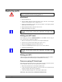
1
GUNNAR 601
User Manual
By GUNNAR Weissenberger AG
11.2002
Weissenberger AG
Staatsstrasse 119
CH-9445 Rebstein
Tel: +41 (071) 775 82 20
Fax: +41 (071) 775 82 29
Internet: www.gunnar-europe.com
GUNNAR is a registered Trademark of Weissenberger AG, Switzerland
Contents
General information
1
Introduction ...............................................................................................................................1
Safety advice .............................................................................................................................1
Intended purpose .......................................................................................................................2
Liability......................................................................................................................................2
Data protection..........................................................................................................................2
Overview
3
Overview, Fig .01......................................................................................................................3
Z-Head Fig.02 ...........................................................................................................................4
Bladehead 45° Fig.03................................................................................................................5
Bladehead 90° Fig. 04...............................................................................................................6
Controller Fig.05.......................................................................................................................7
Maintenance unit Fig.06 ...........................................................................................................8
Installation
9
Supplied with machine..............................................................................................................9
Unpacking and set up ................................................................................................................9
Adjusting the table angle ....................................................................................................... 10
Stand, Fig 08........................................................................................................................... 11
Installation of the machine .................................................................................................... 12
Connecting up the 601 ............................................................................................ 12
First Installation of the SPT32 Software ............................................................................. 13
Update SPT32 Software ........................................................................................................ 13
Technical Data
15
Space Requirements, 601XL................................................................................................. 15
Measurement and Weight ...................................................................................................... 15
Electrical connection.............................................................................................................. 16
Power supply ........................................................................................................... 16
PC connection / settings......................................................................................................... 17
Pneumatic connection............................................................................................................ 17
Environment ........................................................................................................................... 17
Cutting data............................................................................................................................. 17
Operating the GUNNAR 601
18
Starting the SPT32 Software ................................................................................................. 18
Switching off the system ....................................................................................................... 18
Insert cardboard...................................................................................................................... 19
Changing blade ....................................................................................................................... 19
Button clamping system ........................................................................................................ 19
Machine settings..................................................................................................................... 20
Reading in the basic settings .................................................................................. 20
Basic settings ........................................................................................................... 20
Compressed air setting............................................................................................ 20
Blade depth setting.................................................................................................. 21
GUNNAR 601 User Manual
Contents • i
Throttle setting.........................................................................................................21
Servicing
22
Accessories .............................................................................................................................22
Cleaning...................................................................................................................................22
General cleaning ......................................................................................................22
Cleaning the table ....................................................................................................22
Lubrication..............................................................................................................................23
Replacing parts .......................................................................................................................24
Bladehead .................................................................................................................24
Sliding part (45° head) ............................................................................................24
Sliding part (90°) .....................................................................................................24
Pressure spring 45° blade head ...............................................................................24
Pressure spring 90° blade head ...............................................................................25
Repairs.....................................................................................................................................25
Error removal
26
Errors and removal..................................................................................................................26
Status lamp doesn't light..........................................................................................26
Machine does not work – green lamp is on ...........................................................26
Machine does not initialize .....................................................................................26
No Movement in X -, Y- or Z Axis ........................................................................27
Button clamping system does not work .................................................................27
Guarantee
28
Guarantee provisions ..............................................................................................................28
ii • Contents
Index
29
Registry Form
31
GUNNAR 601 User Manual
General information
Introduction
The information contained in this Document corresponds to the latest
developments at the time of publication. Printing errors and mistakes cannot be
excluded.
We reserve the right to make design modifications or to deviate from the designs
shown.
Safety advice
Please read the following safety advice before installing, operating, servicing or
repairing the machine.
• The installation, servicing and repair of the machine should be carried out
solely by a GUNNAR trained service engineer.
• Care should be taken to observe the installation instruction for the machine
and in particular the ambient conditions.
• The machine should be operated by trained personnel only. Your GUNNAR
distributor will provide training .
• Any unauthorized modification or opening of the controller will
automatically render the product guarantee and the safety guarantee invalid.
• Contact your GUNNAR representative before installing accessories.
• For Security reasons the machine should be served one person only.
GUNNAR 601 User Manual
General information • 1
• Even with long lasting working procedures, the operator always has to be
present because of security.
Intended purpose
The 601 has been designed exclusively to cut cardboard for mounts.
Liability
Weissenberger AG will not assume any product liability in the event of incorrect
handling or use of the Software, the machine or its components. Weissenberger
AG is not responsible for any loss of data. We recommend that that you save
your data in a backup file on a regular basis.
Data protection
Weissenberger AG is owner and holder of all the rights. Neither the machine
data nor any of the Software may be made available to third parties.
2 • General information
GUNNAR 601 User Manual
Overview
Overview, Fig .01
2
4
11
3
10
8
8
7
5
6
1
1.
Stand
7.
Panel
2.
Table
8.
Clamping Knobs
3.
Y-Arm
9.
Cablechain
4.
Z-Head
10.
X-Motor
5.
Emergency Stop
11.
Y-Motor
6.
Start Button
GUNNAR 601 User Manual
Overview • 3
Z-Head Fig.02
10
4
5
7
6
9
3
8
1
2
Article
Number
1.
Bladehead 45°
300043
2.
Bladehead 90°
300042
3.
Cylinder for 90°
SMC_CQSB_20_25D
4.
Electrovalve
SY3420 – 5MOU – C4 - Q
5.
Electrovalve
VZ110 – 5MOZ – M5
6.
Z-Sensor
MK11-1A71C-500W
7.
One way restrictor
SMC_AS1201F-M5-04
8.
Z Motor
VRDM366-50LHA
9.
Connector Board
300116
10.
Electrovalve
SY3120 – 5MOU – C4 - Q
4 • Overview
GUNNAR 601 User Manual
Bladehead 45° Fig.03
7
4
8
1
3
Min. 4,4mm
(see Page 24)
2
5 or
6
Article
Number
1.
Knurled Screw
100058
2.
Clamping part
300015
3.
Sliding part
300011
4.
Blade Holder
100086
5.
Blade thick
20011
6.
Blade Thin
20012
7.
Locking Screw
Allen screw M5 x 16
8.
Pressure spring
Feder 44_2_3
GUNNAR 601 User Manual
0.7mm
(see Page 24)
Overview • 5
Bladehead 90° Fig. 04
7
2
4
3
8
9
5
1
6
Article
Number
1.
Knurled Screw
300023
2.
Spring
300128
3.
Clamping arm
300013
4.
Clamping plate
300014
5.
Sliding part 90°
300012
6.
Sliding part holder 90°
300114
7.
Locking screw
Allen screw M5 x 16
8.
Setscrew
M3 x 4
9.
Sliding part axis
300115
6 • Overview
GUNNAR 601 User Manual
Controller Fig.05
7
1
2
X3
X1
X7
X6
X5
X4
X2
3
4
5
6
8
1.
Socket for current
7.
X3 = Comport – PC RS232
2.
Power supply selection switch
8.
X2 = Y-axis
3.
X7 = Motor Z-axis
9.
X1 = X-axis
4.
X6 = Signals stand
5.
X5 = Z-Head
6.
X4 = reserve
GUNNAR 601 User Manual
9
Overview • 7
Maintenance unit Fig.06
1
2
4
5
3
Article
1.
Airhose Connection
2.
Pressure Reduction w. Manometer f. clamps
3.
Labeling for Clamping system
4.
Pressure Reduction w. Manometer f. head
5.
Labeling for Bladehead
8 • Overview
Number
TA26910
TA26910
GUNNAR 601 User Manual
Installation
Supplied with machine
Article
Number
User Manual
Allen key 1.3 mm
Allen key 2 mm
Allen key 4 mm
Allen key 5 mm
Allen key 6 mm
10 Blade holder
100086
200 Blade 20012 thin
20012
Machine Adjustment disk
1 Installation CD
1Test mat
Unpacking and set up
In order to achieve the best possible cutting Quality, make sure that the machine
is placed on an even and strong ground (preferably concrete). The set up and the
Installation should be carried out solely by a GUNNAR trained service engineer.
1. Open the machine packaging and remove the box with accessories.
2. Check the scope of delivery.
3. Lift the 2 pre-assembled side parts (Fig.08 No.2 and 3)out of the box.
4. Adjust the angle of the table at both sideparts (0°, 8° or 16°).see&"Chapter
"Adjusting the table angle".
5. Stick on the Rubber buffer at the legs.
6. Align the sideparts ( Fig.08 No.2 and 3)at the location where the machine
will finnaly be placed.
7. Remove the intermediate carton layer.
8. Lift the front –(Fig.08 No.4) and the back part of the stand (Fig.08 No.1) out
of the box.
9. Assemble the backpart (Fig.08 No.1) and the sideparts (Fig.08 No.2 and 3)
with the provided allen screws M6 x 12. Just tighten the screws slightly.
10. Lift the Table out of the box directly onto the stand and fix it with the M6 x
20 screws.
11. Connect the machine as described in &"Chapter Connecting up the
601page 12.
GUNNAR 601 User Manual
Installation • 9
12. Mount the front cover ( Fig. 08 No.4).
13. Tighten all the screws on the machine stand.
14. Check now whether the machine has a strong stand and test with help of a
spirit level if the machine table is absolutely even.
15. The original packaging must be kept for the duration of the guarantee
period.
Adjusting the table angle
Fig.07
0°
8°
16°
1. Loose the screw (M8 x 16)on the front side of the sidepart.
2. Remove the screw (M8 x 16)on the backside of the side part.
3. Move the profile in the position where you want to adjust the table. The
whole on top is 0° angle. The middle one for 8° and the bottom one for 16°.
Please note that the best results can be reached with an absolute
horizontal table, that means 0° table angle.
4. Tighten the the screw on the front and on the backside of the side part.
5. If the table is allready mounted on the stand, loose both screws on the front
side (left and right side of the table).
6. Remove both screws on the backside of the side part.
7. Lift the table from the backside in this position you want to work with (0°,
8° or 16°).
8. Insert the screws on the backside into the accordingly wholes.
9. Tighten all 4 screws.
10 • Installation
GUNNAR 601 User Manual
Stand, Fig 08
6
5
8
7
2
1
9
3
10
4
Article
Number
1.
Stand – back part
105179
2.
Side part right
105196
3.
Side part left
105195
4.
Stand - Frontcover
105180
5.
Rubber-buffer
6.
Allen Screw M6 x 12
7.
Washer
8.
Allen screw M6 x 20
9.
Power Drive (WDM3)
10.
Controller
GUNNAR 601 User Manual
DIN125-1 A-6,4
Installation • 11
Installation of the machine
Connecting up the 601
Warning: An incorrect wireing can destroy the controller or cause
damages at the machine. Such damage is not covered by the guarantee.
1. Connect the Z-motor cable (green plug) marked with Z, to the Controller
(Fig.08 No.10)(Fig.05 No.03). Attention! A wrong Connection of the Zmotor cable will damage the Z-motor.
2. Connect the X- and Y-motor cable (green plugs) marked with X and Y to
the WDM3 (Fig. 08 No.09).
3. Plug in the blue ribboncable with the D-Sub plug to the Controller (Fig.08
No.10)(Fig.05 No05).
4. The cable for the Start button has to be connected with the white plug in the
Cabelchannel above the Controller.
5. Connect the black 6mm air hose with the Pressure Reduction (Fig.06
No.04)
6. Connect the clear and the black 4mm air hoses to the Valves beside the
Controller. NB: COE-mode will not work if the hoses are mixed up.
7. Connect the five-wire cable like on the diagram below.
8. Put the cables, wires and hoses carefully into the cable channel and mout the
cover of the channel.
9. Connect the compressed air to the Ø8 mm connection sleeve (see Fig.06
No.2). The consumption and the necessary pressure are specified in the
technical data.
10. Check the main voltage at the Controller and the Powerdrive. If the main
voltage switch (Fig.05 No.2) is not already set to the standard voltage for
your country, then change it now.
NB: If the input voltage is incorrectly set, this can destroy the controller.
Such damage is not covered by the guarantee.
11. Connect the the main power supply (Fig.05 No.1). using the main cable,
article No. 12.03.6510, which is supplied (the plug required for your country
must be affixed by a qualified person).
12 • Installation
GUNNAR 601 User Manual
First Installation of the SPT32 Software
1. Start your PC.
2. Insert the SPT32 CD ROM into CD ROM drive.
3. If the program doesn't start automatically, do as follows:
4. Press Start button an Run.
5. Type in D:\autorun.exe (or name of CD ROM drive:\autorun.exe).
6. Press Enter.
7. In the main menu select Software and then SPT32.
8. Follow the instructions in the setup program.
9. The setup program will ask for "Machine Adjustment" . Please insert this
disk into floppy drive A:.
10. Please configure Windows &"Chapter, PC connection / settings".
Update SPT32 Software
1. Start your PC.
2. Insert SPT32 Installationdisk 1. into drive A: or CD ROM into CD ROM
drive and do as follows:
3. Press Start button.
4. Run.
5. Type in A:\setup (or name of CD ROM drive:\setup).
6. Enter.
7. Follow the instructions in the setup program.
8. During the installation, setup will ask for the "Machine Adjustment"
disk. Do not fit the disk into drive A:, just click OK. (If you do insert a
disk you will overwrite the actual machine setting)
9. The SPT32 readme.txt file in the "SPT32" directory contains special
instructions. This informative text file should be read once the
installation is completed.
GUNNAR 601 User Manual
Installation • 13
Technical Data
Space Requirements, 601XL
The 601 is operated from the front.
Fig. 07
GUNNAR 601 User Manual
Technical Data • 15
Measurement and Weight
GUNNAR 601 XL
Max. Matboard size
1560 x 1042mm
61.40 x 41.00 “
Dimensions L/W/H
1992/1410/1130 mm
78.4/55.5/44.5 “
Weight
135 Kg
298 lbs
Electrical connection
The 601 requires a flawless electrical installation with an a ground (GND) before
it can be connected.
Power supply
NB: The power level must not fall short at any circumstances (not even for
short terms).
Power supply voltage
230V +/- 13%
115V +/- 13%
Power consumption
230V 3A
115V 6A
(Check also „Connecting up the 601“ page 12)
16 • Technical Data
GUNNAR 601 User Manual
PC connection / settings
The PC must have at least one free COM interface with a FIFO UART 16550
compatible module. Preferably this should be COM1. Plug in the AT Link cable
which is already connected to the machine.
Operating system: Windows 95/98, Windows ME, Windows XP, NT4.0 or
Win2000 ™.
PC
RAM
CD ROM
Screen resolution
min. Pentium 400 (or comparable CPU)
min. 32Mb
min. 4x Speed
min. 800 x 600 Pixels
recommended 1024 x 768
Pneumatic connection
min. Line pressure (dry)
max. compressed air consumption
6 Bar (90psi)
40L / min
Environment
Ambient temperature
Relative humidity
10 - 35 °C / 50 - 95 °F
30 - 70 %
The location of the machine must be held as dust-free as possible.Neither dust
nor other contaminations should reach the electronics-parts (see Guarantee
provisions).
The machine must be free of water contact. Furthermore, no explosive dust – air
or gas – air mixture should reach the machine.
Cutting data
max. cutting speed
max. cutable matboard thickness
min. cutting radius*
625 mm (25 Inch) / Second
3.5 mm (0.14 Inch)
0.5 cm (0.2 Inch)
*This is the smallest Radius the machine is able to cut. But the constitution of
the matboard and the condition of the blade influences the quality of the cutting
as well as the perfect machine adjustment.
GUNNAR 601 User Manual
Technical Data • 17
Operating the GUNNAR 601
Starting the SPT32 Software
Follow the steps below to start the SPT32 Software
1. Start the PC.
2. Wait until your operating system is started completely.
3. Switch on the GUNNAR 601 by turning the Main-switch/Emergency stop
(Fig.01 No.6) right to get loose.
4. Click the Start button.
5. Then open Programs
6. SPT32 (Programgroup)
7. SPT32 (Icon)
Operating instructions and register information for the SPT32 Software may be
found in the SPT32 Help manual delivered with the machine or in the Help
program. This can be started from inside SPT32 by pressing the "F1" key, or "?"
for direct help. Without SPT32, the help program can be started from within the
SPT32 program group. Also you can find all the manuals ( Help, Tips&Tricks,
Configuration Assistant and User Manual ) on our GUNNAR CD-ROM. If your
personal copy is not with the machine ask your GUNNAR Dealer for a current
one.
You can download the manuals from our Homepage, www.gunnar-europe.com
in a printable PDF format. Please note that Adobe Acrobat Reader is necessary
to read the manuals. Use the same password as for the Softwaredownload.
Switching off the system
To switch off the system, proceed as follows:
1. To instantly exit SPT32 press the "Alt" + "F4" keys or via the menu – file Exit. <"SPT32 Help, Chapter Switching off".
2. Switch off your GUNNAR 601 by pressing the Main switch / Emergency
stop (Fig.01 No.6)
3. Shut down your operating system.
4. Switch off the PC.
5. If the 601 is not used for a longer period, the compressed air should
similarly be switched off and the machine covered.
18 • Operating the GUNNAR 601
GUNNAR 601 User Manual
Insert cardboard
To cut a cardboard you must use underlay sheets. We recommend to use a sheet
with a thickness of 1.3mm. Normally, it is ideal to use the same material as the
material to be cut. If that is not possible, a harder carton is should be used. Please
note, different materials influences the wear of the knife in different manner.
Tip:Your working procedure will be easier if you stick the underlay sheeton the
working table, for example with a glue double-sided ATG tape.
Changing blade
When SPT32 is running, press the "Ctrl" + "F5" keys to have the blade heads
moved into the "change blade " position, making the clamping screw (Fig.03
No.1 and Fig.04 No.1) accessible. Turn the clamping screw anti-clockwise to
release the blade. The blade can now be pulled out with the blade holder (Fig.03
No.2).
Fig. 09
1
2
4
3
1.
Tongue
2.
Blade holder
3.
Blade
4.
Setscrew
Press on the tongue (Fig.09 No.1) on the blade holder to pull the blade out and
insert a new one.
Make sure that the blade holder will be pushed down when you insert the blade,
then tighten the clamping screw solidly.
Take care that the blade is inserted in the right direction, see Fig 09 Nr 3.
Button clamping system
The GUNNAR 601 works with a Button Clamping system in X- and Ydirection. To make a COE mode possible (see SPT32 Help ) the buttons on the
left on the right hand side can opreate in opposite way.
GUNNAR 601 User Manual
Operating the GUNNAR 601 • 19
To be able to cut until the edge of the board, the single buttons can be pushed
down. The buttons must be twisted by 180° to do that. Twisting is easier if the
button is pressed in a little bit before doing so.
For detailed Information regarding how to use this function read the SPT32
Help.
Machine settings
Reading in the basic settings
The Software settings are supplied with the GUNNAR 601 on a diskette labeled
"Machine Adjustment". Instructions for installation the data may be found in
<"Chapter, Installation of SPT32 Software".
Basic settings
Instructions for implementing the basic settings are given in the Help program.
See <"Chapter, Start SPT32 Software" or in the "Configuration Assistant".
Compressed air setting
Blade head
The compressed air setting for the blade head can be adjusted via the pressure
reduction (Fig.06 No.5). The basic setting is 3.5 bars. If excessively pronounced
pressure marks are left on the cardboard during cutting, it is possible to reduce
the blade head pressure to approximately 2.5 bars. If the blade does not fully cut
through thick, hard cardboard at the start of a cut, the pressure can be increased
to a maximum of 5 bars.
Clamping system
The compressed air setting for the clamping system (knobs) can be adjusted via
the pressure reduction (Fig.06 No.1). The basic setting is 3.5 bars. If very soft
board is used, the air pressure can be reduced to 3 bar.
20 • Operating the GUNNAR 601
GUNNAR 601 User Manual
Blade depth setting
The blade depth must be set so that the backing material is cut into by 0.3 up
to 0.5 mm. To adjust the blade depth follow these instructions.
1. Make sure that the initial blade depth is not set too deep (turn set screw
on holder in for a more shallow cut) for the first cut. This will avoid
damaging the table top.
2. Cut a rectangle
3. Check the depth of the cut in the underlay sheet.
4. If the cut is too deep, use the 1.3 mm hexagon socket screw key supplied in
your installation kit to adjust the blade holder. Turn the screw on holder in
(clockwise) for a shallower cut. If the cut is not deep enough, then unscrew
the screw (anti-clockwise). One turn is a app. 0.3 mm ( 0.012 Inch) dept.
5. Repeat steps 2 to 4 until the cut is some 0.3 to 0.5mm (0.012 to 0.019 Inch)
deep.
6. It is customary to set up different blade holders for various cardboard
thickness that you may be cutting.
Throttle setting
In the case of circles and other shapes, where the blade cannot be inserted in a
corner but only in a curve, a throttle is used. This ensures that the blade is
inserted more slowly and does not leave any insertion marks on the mount.
Further information on this setting may be found in <"SPT32 Help, Chapter
Throttle".
GUNNAR 601 User Manual
Operating the GUNNAR 601 • 21
Servicing
Accessories
The following accessories are available at extra cost.
Article
Number
Blades 0.62mm thick
A-20011
Blades 0.5 mm thick
A-20012
Further information is available from your GUNNAR dealer or from the
Internet, www.gunnar-europe.com.
Cleaning
NB: All cleaning and maintenance work must be conducted with the
machine switched off and the main plug pulled out. On the machine only a
dry cleaning is allowed.
General cleaning
Cleaning the GUNNAR 601 is an essential part of servicing. The cleaner it is
kept, the longer its service life will be. The GUNNAR 601 should be kept dustfree and free from bits of cardboard and fibers. This is best done by sucking up
the dust. Dust should only be blown out when cleaning the guides. Please read
the following chapter.
NB: When blowing out the guides, always blow away from the carriage.
Otherwise the dust will come into the bearings and can disturb them.
Cleaning the table
The table top can additionally be cleaned with a glass-cleaning agent or
detergent.
Do not use solvents.
22 • Servicing
GUNNAR 601 User Manual
Lubrication
The bearing bushes, that are used for the leadership of the cylinder-shafts, must
be lubricated intermittently all 15 000 cuts .
1. Remove the Z-Head cover.
2. Clean both shafts .
3. Grease the shafts easily.
4. Move both bladeheads up and down by hand for a couple of times, in order
to serve the grease on the shaft evenly.
5. Remount the Z-Head cover again.
GUNNAR 601 User Manual
Servicing • 23
Replacing parts
NB: All cleaning and maintenance work must be conducted with the
machine switched off and the main plug pulled out.
Bladehead
1. Shut the Machine off.
2. Turn the blade head and Undo the locking screw with the 4 mm hexagon
socket screw key (Fig.03. No.7 or Fig.05. No.7) .
3. Switch on the machine to make sure that the head is in the upper position
(SPT32 has not to be started).
4. Pull the blade head down and insert the new one.
5. Tighten the locking screw again.
NB: Replacing the blade head can alter the boarder and opening
dimensions on the mount. Check these dimensions and adjust them if
necessary.
Sliding part (45° head)
If the sliding part attains its minimum thickness of 4.4 mm at the base (Fig 03
No.3), then it must be replaced as follows.
1. Remove the blade head as described in &"Chapter, Blade head".
2. Undo the screw located in the sliding part (Fig.03. No.3 )
3. Remove the sliding part and screw on the new one.
4. At the 45° bladehead adjust the bit stop screw to 0.7mm (Abb.03)
5. Attach the blade head again.
NB: Replacing the sliding part can alter the boarder and opening
dimensions on the mount. Check these dimensions and adjust them if
necessary.
Sliding part (90°)
After the change of the sliding part 90° head no adjustments necessary. Please
check the depth of the blade and adjust the bladeholder if necessary.
Pressure spring 45° blade head
The pressure spring (Fig.03. No.3) is a part subject to wear. If it breaks, then it
must be replaced. The procedure for replacing it is as follows
1. Remove the blade head as in &"Chapter, Blade head"
2. Pull out the broken spring and insert a new one. Take care to ensure that the
spring is located in the recess provided for it.
3. Attach the blade head again as in &"Chapter, Blade head"
Please note: it is not necessary to dismantle the Blade head!
24 • Servicing
GUNNAR 601 User Manual
Pressure spring 90° blade head
The pressure spring is a part subject to wear. If it breaks, then it must be
replaced. The procedure for replacing it is as follows
1. Remove the blade head as in &"Chapter, Blade head"
2. Loose the setscrew (Fig.04. No.8) and pull out the sliding part axis (Fig.04.
No.9) .
3. Pull out the broken spring and insert a new one.
4. Grease the sliding part axis.
5. Replace the setsrew so again that the sliding part axis itself can move in the
pretended lifting .
6. Attach the blade head again as in &"Chapter, Blade head"
Repairs
Most repairs can be performed by the customer, simply by replacing parts.
If a service or a major repair is necessary, then this must be performed by a
specialist. Please contact your authorized GUNNAR dealer.
GUNNAR 601 User Manual
Servicing • 25
Error removal
Errors and removal
Status lamp doesn't light
Problem
What is to be done?
24 V Lamp in the green button does not
light.
1.
Check the power supply at the plug and the controller
2.
Is the emergency stop off?
3.
Check the pin and socket connector in the cable chain in the
stand.
Machine does not work – green lamp is on
Problem
What is to be done?
24 V Lamp in the green button does light,
but machine doesn't run.
1.
Check the connection of the datacable from PC to machine.
2.
Switch off the machine and close SPT32 again.
3.
Switch on machine and wait until the controller has booted
(Beeping noise), then start SPT32 again.
Machine does not initialize
Problem
What is to be done?
After the start of the program the intializing
starts but the blade head rotate
continously.The Initialization will not be
done.
1.
Blade head was not lifted.
2.
Blade head was lifted..
26 • Error removal
Has the blade-head been lifted when starting the software?
Check whether compressed air exists?
3.
Is the compressor switched on and the main switch of the
compressed air supply open?
4.
Check the distance between the Z-sensor and the white gear.
5.
Check the Z-sensor by an electrician.(Fig.02 Nr.06)
GUNNAR 601 User Manual
No Movement in X -, Y- or Z Axis
Problem
No Initialization after the start, even no
movement in X- and Y-direction.
1.
If you can move the axis by hand, there is no
2.
electric potential at the motor.
3.
4.
What is to be done?
Check if you can move the axis by hand even when the machine
is switched on.
Check the plugs and the cable to the Controller (Fig.08 Nr.10)
and to the power drive (Fig.08 Nr.09).
Do the red LEDs at the power drive (WDM3) in the stand,
sending an error message? Please contact your GUNNAR
Dealer.
Switch off the GUNNAR 601 with the emergency stop and start
again. Do you hear a beeping noise in the Controller after a
short boot sequence ?
No Beeping noise.
5.
Is power at the Controller ?
There is power but no beeping noise.
6.
Contact your GUNNAR Dealer.
No axis can be moved by hand
7.
Contact your GUNNAR Dealer.
Button clamping system does not work
Problem
One or more buttons wont move up and
down.
One ore more knobs wont let them move by
hand or just not easily.
GUNNAR 601 User Manual
What is to be done?
1.
Check the compressed air settings (Min. 3 Bar).
2.
Switch off the compressed air and move the button up and down
by hand. Can you do it easily?
3.
Check the air hoses under the table.
4.
Contact your GUNNAR Dealer.
Error removal • 27
Guarantee
Guarantee provisions
The guarantee on the GUNNAR 601 runs for one year as of the date of delivery
or for a maximum of 200.000 mount cuts (holes). The guarantee covers defects
due to material faults or production errors.
Damage due to negligent and incorrect handling is not covered by the guarantee.
Damages that has originated through a strong contamination or elevated dustsettlement on the electronics-parts are excluded from the guarantee.
Normal wear is similarly excluded from the guarantee (assessment by us).
Kindly observe our general terms and conditions in this respect.
28 • Guarantee
GUNNAR 601 User Manual
Index
Accessoires 22
Installation 1, 16, 17–18, 20–21
Installation of the machine 12
Intended purpose 2
Introduction 1
B
L
Basic settings 20
Blade depth setting 21
blade holder 5, 9, 19–21
Bladehead 4–6, 24
Liability 2
Lubrication 23
C
Machine does not work – green lamp is on 26
Machine settings 20
Maintenance unit 8
Measure and Weight 16
A
Changing blade 19
Cleaning 22
Cleaning the table 22
Compressed air setting 20
Connecting up the 3001 12, 16
Controller 1, 7
Cutting data 17
M
O
Operating the GUNNAR 3001 18
Overall view of the 3001 3
D
P
Data protection 2
Panel 3
PC connection / settings 13, 17
Pneumatic connection 17
Pressure spring 45° blade head 24
Pressure spring 90° blade head 25
E
Electrical connection 16
Environment 17
Error removal 26
Errors and removal 26
F
R
Reading in the basic settings 20
Repairs 25–28
Replacing parts 24, 25
First Installation of the SPT32 Software 13
S
G
General cleaning 22
Guarantee 1, 10, 28
Guarantee provisions 28
I
Insert cardboard 19
GUNNAR 601 User Manual
Safety advice 1
Servicing 1, 22
Sliding part 5–6, 24–25
Space Requirements 15
Starting the SPT32 Software 18
Status lamp doesn't light 26
Supplied with machine 9
Switching off the system 18
Index • 29
T
Z
Throttle setting 21
Z-Head 4, 7
U
Unpacking 9
Update SPT32 Software 13
30 • Index
GUNNAR 601 User Manual
Registry Form
GUNNAR - 601
Machine No.:
Controller No.:
Company name:
Contact person:
Street:
City:
Zip Code:
Country:
Fax-no:
Email Address:
Key number:
(You will get this number during the first start of SPT32)
Please Mail or Fax this form to:
Weissenberger AG
GUNNAR
Staatsstrasse 119
CH-9445 Rebstein
SWITZERLAND
Fax:
+41 71 775 82 29
GUNNAR 601 User Manual
Registry Form • 31
32 • Registry Form
GUNNAR 601 User Manual