1
NTI XTENDEX USB AND VGA VIDEO EXTENDER
Connect The CATx Cable
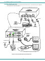
Connect the CATx cable(s) between the “Cat 5” port(s) on the Local and Remote Units. (See Figure 5.) When properly
inserted the cable end should snap into place. If your model has two “CAT5” ports, be sure to connect the cables to the
same numbered ports at each end (connect port 1 at the Local to port 1 at the Remote, and port 2 to port 2).
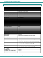
See Resolution/Distance Chart on page 10
Figure 5- Connect CATx cables
!
WARNING: Never connect the XTENDEX to an Ethernet card, Ethernet router, hub or switch or other
Ethernet RJ45 connector of an Ethernet device. Damage to devices connected to the Ethernet may result.
Plug-in and Boot Up
1.
Plug the power cord from each monitor into a power outlet.
2.
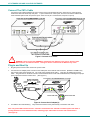
Connect each AC adapter power connector to the 5VDC ports on the Remote and Local Units. (Model ST-C5USBVT only
has a power supply at the Remote Unit. The Local Unit is powered by the CPU.) Plug each AC adapter into a power
outlet. The green LED on the RJ45 connector of both the Remote and Local Units should illuminate, indicating that a proper
power connection has been made to them. (See Figure 6.)
Power Connector
5 VDC
AC
ADAPTER
Front View of ST-C5USB2V2ARST Local Unit
5VDC @ 3.0A OUTPUT
(Outside
(Inside
barrel)
barrel)
1.3 mm x 3.5 mm Female
Barrel
MONITOR 2
-
5VDC
3A
1
CAT 5
2
MONITOR 1
+
DDC
NETWORK TECHNOLOGIES INC 1275 Danner Dr, Aurora, OH 44202 Tel:330-562-7070 www.networktechinc.com
Yellow Traffic LED
Green Power LED
Figure 6- Connect the AC adapter(s)
3.
Turn ON the CPU and Monitor(s).
They should each react as if they were directly connected to each other.
Note: The yellow LED on RJ45 connector “CAT5 #1” will illuminate and “CAT5 #2” will blink anytime data traffic is
passing between the Local and Remote Units, indicating proper CAT5 cable connection and communication.
(See Figure 6)
8