1
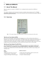
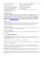
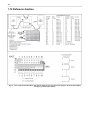
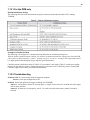
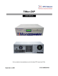
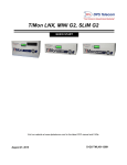
DPM & DPM-216
USER MANUAL
May 21, 2009
D-OC-UM09.521200
Firmware Version - DPM: 2.1I
Firmware Version - DPM216: 1.0A
Revision History
May 21, 2009
Released updated D-OC-UM09.521200
March 12, 2009
Released updated D-OC-UM093.12100
January 23, 2009
Released D-OC-UM09.23100
This document contains proprietary information which is protected by copyright. All rights are reserved. No part of this
document may be photocopied without prior written consent of DPS Telecom.
All software and manuals are copyrighted by DPS Telecom. Said software and manuals may not be reproduced, copied,
transmitted or used to make a derivative work, by either mechanical, electronic or any other means in whole or in part,
without prior written consent from DPS Telecom, except as required by United States copyright laws.
© 2008 DPS Telecom
Notice
The material in this manual is for information purposes and is subject to change without notice. DPS Telecom shall not be
liable for errors contained herein or consequential damages in connection with the furnishing, performance, or use of this
manual.
Contents
Visit our website at www.dpstelecom.com for the latest PDF manual and FAQs
1 DPM and DPM-216
1
1.1 About This Manual
1
1.2 Overview
1
1.2.1
2
Possible Applications
1.3 Specifications
3
1.4 Technical Description
4
1.4.1
DPM only
1.5 Echo Mode Applications
5
5
1.5.1
DPM in Echo Mode
5
1.5.2
DPM-216 in Echo Mode
6
1.6 Installation
7
1.7 Hardware Connections for the DPM and DPM-216
8
1.8 Alarm Input Tutorial
9
1.8.1
Dry Contacts
10
1.8.2
Contact to Battery
10
1.8.3
Contact to Ground
11
1.8.4
TTL Output
11
1.9 How To Read Pager Displays (For the DPM only)
12
1.9.1
Alphanumeric Pager
12
1.9.2
Numeric Pager
12
1.9.3
ASCII Terminal
13
1.10 Operation
13
1.10.1 For the DPM only
14
1.10.2 ASCII Control (228-Series Models)
16
1.11 LED Display Descriptions
18
1.12 Reference Section
19
1.12.1 For the DPM only
20
1.12.2 Troubleshooting
20
2 Technical Support
21
3 Warranty
22
4 End User License Agreement
23
1
1 DPM and DPM-216
1.1 About This Manual
There is a separate user manual for T/DPMW. You are reading the hardware manual for the DPM and
DPM-216.
This Hardware Manual provides instructions for hardware installation and operating the unit. The T/DPMW
User Manual, included on the Resource CD, provides instructions for provisioning and monitoring the DPM and
DPM-216 using the software utility.
1.2 Overview
Fig. 1 - The compact design of the DPM and DPM-216 allow for mounting on any flat surface.
The Discrete Point Module (DPM)
DPS’s Discrete Point Module, teamed with your local pager service, will let you know when you have an
important event occurring at some isolated location. The DPM can detect any event that can be translated into an
electrical contact closure, such as a micro switch or relay. Door openings and equipment failures are typical
events that it can report to your pager or cell phone. In addition, you can contact the DPM from any tone dialing
telephone and, by password identification, activate remote devices like door locks or security lights.
The Discrete Point Module 216 (DPM-216)
The Discrete Point Module 216 is connected to a central monitoring device via a dedicated communications
facility. The DPM-216 is a fixed-facility version of the DPM, with RS232, RS422, RS485 or 202 Modem
interface. These are the main differences between the DPM and DPM-216. The DPM-216 can also detect any
event that can be translated into an electrical contact closure, such as a micro switch or relay, to notify you of
important events.
DPM
Features:
· Pages you when critical events occur
· 16 Alarm inputs, 2 control outputs
· Supports both alpha and numeric pagers
DPM-216 Features:
· Notifies the central monitoring station of critical events
· 16 alarm inputs, 2 control outputs
· Compact, economical package
2
·
·
·
·
·
·
·
·
Compact, economical package
DTMF phone control
Interface large networks via dial facility
Reports to IAM or T/MonNOC Masters
Download configuration from a PC
Automatically operate derived controls
Optional ASCII craft port access
AC or DC powered
·
·
·
·
·
·
Interface large networks via dedicated facility
Reports to IAM or T/MonNOC Masters
TBOS or DCP family protocols
Download configuration from a PC
AC or DC powered
Non-volatile RAM maintains configuration when off
Configuration Software
The DPM has programmable features such as back-up pager numbers and written alarm point descriptions. The
DPM-216's programmable features include alarm descriptions and polarity. Configuring these features is easy
using T/DPMW, a Windows-based software provided with the unit at no extra charge. Programming is done
locally through the serial port of a computer (for both units) or by dialing the DPM from any modem-equipped
PC (DPM only) The software will also monitor the alarm states and operate control relays. To download
T/DPMW, go to www.dpstele.com/support. Login and click on the "Firmware / Software Downloads"
button.
Derived Controls
In addition to being activated remotely, control relays may be activated internally by a combination of existing
alarms, using a programmable equation (derived control). Each control point may have up to two equations
defined. For example, maybe you'd like to toggle a relay every time a door alarm is triggered.
ASCII Craft Port Access
Some models of the DPM allow you to connect a remote computer through DPM port to an ASCII craft port on
another piece of equipment, such as a PABX or channel bank.
Discrete Control Module
The Discrete Control Module (DCM) is a full complement to the DPM and DPM-216, providing 2 alarm points
and 16 controls.
1.2.1 Possible Applications
Telecommunications - The DPM is just right for remote cell sites and small offices, where 16 alarms and 2
controls are sufficient. In addition to pager reporting, the DPM may forward elected alarm points to a central
network management system.
The DPM dials the master and reports with TRIP protocol or ASCII messages.
The DPM-216 contacts the master and reports with TBOS, DCP, DCPf, or DCPs protocol via RS232, RS422/485
or 202 modem on dedicated facility.
Agriculture - A DPM or DPM-216 in a barn or other out-building can notify you of an unauthorized entry,
temperature extreme, fire, low water pressure, pump operation, etc. With the DPM’s remote control capability
you can operate door locks, security lights and pumps.
Refrigeration - The DPM and DPM-216 can monitor freezer doors, temperature sensors, compressor operation
and power lines to warn off-site personnel of impending problems, before they cause significant losses.
Fire and Safety - The DPM and DPM-216 can monitor smoke and sprinkler pressure alarms, door and window
openings in industrial and commercial facilities, pin-pointing trouble spots for responding emergency teams, 24
hours a day.
3
1.3 Specifications
Alarm Point Inputs
Uni-polar inputs.
TTL Inputs
Dimensions
Relays
Mounting
Power Input
Fuse
Heat Dissipation
Modem
DPM Protocols
DPM-216 Protocols
Connectors
Comm. Facility Interface
(For the DPM-216 only)
Operating Temp.
Humidity
LEDs
16 optically-isolated bi-polar inputs. (Connect to Gnd and Batt to alarm.)
(OPTIONAL; Close contact across terminals to alarm.)
(OPTIONAL) Referenced to +5 VDC through 2.2K ohm resistor
Ground one side of input through TTL circuit to alarm
7.0"(L) X 5.0"(W) X 1.5"(D)
2, Form “A”
Rated Load = 0.5A 125VAC, 1A 24VDC
Contact Material = Gold-Clad Silver
Max. Switching Power = 62.5VA, 30W
Max. Switching Current = 1A
Max. Switching Voltage = 60 VDC/125 VAC
Max. Carrying Current = 2A
Two keyhole mounting holes on back vertically spaced 1.75" apart.
21ma @ +/-48 VDC (1 Watt)
42ma @ -24 VDC (1 Watt)
84 ma @ +/-12 VDC (1 Watt)
A 120 VAC wall mount transformer is supplied with the -24 VDC unit.
125 mA.
35 BTU @ 24 or 48 VDC
212 “AT Type” 300/1200 Baud DTMF/Internal modem with DTMF Receiver
Optional 2400 Baud modem.
T/Mon Remote Interface Protocol (TRIP), TAP Protocol (for Alpha Pagers),
Numeric Pager, text message to cell phone, ASCII (Optional)
TBOS, DCP, DCPf, DCPS
Line = RJ12 (J5)
Configuration or ASCII = Female DB9 (J3) - RS232 or RS485 (optional)
Alarm/Control Points = Female DB37 (J1)
Power = 3.5 mm Mono Jack or screw on (optional) (J4)
Unused = Male DB9 (J2)
RS232 (Option 1V)
202 - 1200 Baud modem (Option 2V)
RS422/485 (Option 4V)
0 degrees to +60 degrees Celsius (32 degrees to 140 degrees F)
0% to 95% non-condensing
Shipping Weight - 4 lbs.
14 front panel
4
1.4 Technical Description
The DPM and DPM-216 use a central microprocessor and interface circuitry for inputs/outputs. Be careful to
observe the polarity option for your unit.
Alarm Inputs
The opto isolated alarm inputs are normally alarmed” when current is flowing. Alarm points can be individually
reversed with the T/DPMW software to be “unalarmed” when no current is flowing. Each input can be
configured for unipolar operation (reports going to alarm state only) or bi-polar operation (reports both going to
alarm state and returning to cleared state). Each point can have a 30 character description, a qualification time
period, backup reporting device number and redial function. Up to four reporting device dial-out numbers can be
stored. The bi-polar inputs have both sides of the opto isolator brought to the connector, permitting ground or
battery activation. (Refer to the input wiring details in Fig. 4 and to the Alarm Input Tutorial. "Bi-Polar Inputs"
can be positive or negative.)
Control Outputs
Form-A contacts are provided, with normally open (N.O.) contacts brought out to pins on connector J1.
Bi-polar Operation and Unipolar Operation describe COS reporting methods. Bi-Polar input describes the
electrical interface at the alarm input.
Fig. 2 – Block diagram/ functional schematic
5
1.4.1 DPM only
Alarms Sent to Pagers or Alarm Center
Reporting Devices -In the event of an alarm, the DPM dials out to either an alpha or numeric pager that
displays the alarm message. It can also call a monitoring center equipped with a DPS T/MonXM or IAM
alarm system or an in-house custom monitoring system. An ASCII reporting version is available that reports
alarms to an ASCII terminal or to a PC programmed to act as an ASCII terminal (model D-PC-221-11A-04).
Fig. 3 Discrete Point Module reports alarms to a variety of devices.
1.5 Echo Mode Applications
Fig. 4 – Echo application uses DPM and DCM back-to-back.
1.5.1 DPM in Echo Mode
In this application the DPM communicates via dial line with a Discrete Control Module (DCM). When the DPM
detects an alarm, it dials the DCM. The DCM relays that correspond to the alarmed points operate, following the
alarm inputs point-for-point. Likewise, the DCM’s two alarm inputs operate the two respective relays at the
DPM. This is especially useful in converting alarms between systems with unlike protocols or for transporting
alarms from small remote sites to large, centrally located remotes or annunciator panels.
An optional Wire Wrap Block with two DB27 cables may be purchased to aid installation. Individual alarm and
relay lines are wire wrapped to the Wire Wrap Block and the DB37 cable is plugged into the DPM, eliminating
6
soldering. Block supports 2 units.
1.5.2 DPM-216 in Echo Mode
In this application the DPM-216 communicates via a dedicated facility with a Discrete Control Module
(DCM-216). When the DPM-216 detects an alarm, it reports directly to the DCM-216. The DCM-216 relays that
correspond to the alarmed points operate, following the alarm inputs point-for-point. Likewise, the DCM-216’s
two alarm inputs operate the two respective relays at the DPM-216. This is especially useful in converting alarms
between systems with unlike protocols or for transporting alarms from small remote sites to large, centrally
located remotes or annunciator panels.
An optional Wire Wrap Block with two DB27 cables may be purchased to aid installation. Alarm and relay
lines are wire wrapped to the Wire Wrap Block and the DB37 cable is plugged into the DPM, eliminating
soldering. The block supports 2 units.
7
1.6 Installation
1. Unpack the DPM and all accessories. Check contents against the shipping list. The installer must
provide alarm contacts (micro switches, relays, etc.) power source, and wires to the alarm and control
points.
2. Mount the DPM. (Use enclosed mounting template and hardware.)
3. The DPM is shipped with all necessary cables for installation. These include the integral power
cable/AC adaptor and the phone line cable. Refer to Fig. 5 in the Hardware Connections section to
ensure a proper connection for each input.
4. Wire Wrap Block: If a wire-wrap block is used with the DPM, the next two steps will be performed.
See wire-wrap manual for details.
a.) Connect alarm points and controls to J1 on the DPM. A DB27 connector and hood are supplied
with the DPM. Shunt J10 if power connects at the power jack and if pin 1 is used for biasing the alarm
inputs to battery.
b.) If using the wire-wrap block, plug the DB27 connector from the wire-wrap block into J1 on the
DPM and connect the alarm and control points per the wire-wrap block operation guide. To operate an
alarm, there must be a current path from the input pin to the alarm return pin. Example: To operate
alarm point 5, pin 25 connects to negative battery (available at pin 1 - install J10 if the power jack is
used), pin 6 connects to positive ground (available at pin 20) and the operating contact is placed in
either leg. See Section 6.
5. If using the wire-wrap block, DC power may be taken through the wire-wrap block at pins F-1 (+) and
F-3 (negative ground). This arrangement utilizes the fusing provided on the wire-wrap block. Power
will come to the DPM through connector J1 and it will not be necessary to use the AC adaptor.
6. Connect the unit to the proper transport:
a.) For the DPM: Connect the RJ12 phone line to the DPM.
b.) For the DPM-216: Connect the RJ12 connector to the facility using the provided cable. The
equipment end of the cable will need to be soldered to the appropriate connector (not included).
7. AC Power: Connect the power adapter to J4, then plug the adaptor into an AC outlet. If using a
Wire-Wrap block, use J4 - do not run AC power through the block. Do not insert a "hot plug" into J4.
8. DC Power: If a DC supply is used power may be connected at J1 pin 1 (- BATT) and pin 20 (+ GND).
The DPM can only be configured with T/DPMW software through the unit's COM1 port OR via phone line. The
DPM 216 does not have a dialup modem and can only be configured with T/DPMW through the COM1 port.
Fig. 5 – The DPM and DPM216 are configured with T/DPMW.
8
1.7 Hardware Connections for the DPM and DPM-216
Fig. 6 – Discrete Point Module hardware connections.
9
1.8 Alarm Input Tutorial
Fig. 7 - Current flow causes alarm
The DPM senses a change of state through current flow in the optical isolators. There are five types of alarm
(current) sources for the DPM: dry contact, contact to battery, contact to ground, TTL outputs and dry contact
(using DPM with internal jumper to battery).
The first three types apply to “regular” DPM’s; the last 2 apply to special options. Use Table A to find the pins to
use for each input for the five types of alarm sources.
Table A - Alarm Input Connections for the Five Types of Alarm Sources
10
1.8.1 Dry Contacts
· Bus the negative side of the optical isolators for all points that use “dry contact” sources (J1 – pins 21-35) to
battery. (Battery is normally available at J1-1. If the DPM power is connected to the jack (J4), jumper J10
should be shunted.) NOTE: “Battery” is negative for -12, -24 and -48 volt options, positive for +12 and +24
volt options. Positive battery options use bi-directional optical isolators, allowing “battery” to be connected to
the negative side of the opto.
· Connect one side of the dry contact source to ground. (Ground at J1-20.)
· Connect the positive side of the optical isolator for the desired alarm point to the other side of the dry contact.
Fig. 8 – Dry contact source wiring.
Dry Contact (DPM only - Using DPM with internal jumper to battery)
Switch or relay with both leads at terminals. DPM inputs have one side of opto internally connected to battery,
one input pin internally connected to ground.
· On those DPM options that have an internal jumper to battery, it is not necessary to add any external jumpers.
All inputs apply a contact across pins 2 & 21, 3 & 22, 4 & 23, etc. All inputs must be the same type with this
option.
Fig. 9 - Dry contact (internal battery) source wiring.
1.8.2 Contact to Battery
· Bus the positive side of the optical isolators for all points that use “contact to battery” sources (J1 - pins 2-17)
to ground. (Ground available at J1-20.) NOTE: “Ground” is positive for -12, -24 and -48 volt options, negative
for +12 and +24 volt options. Positive battery options use bi-directional optical isolators, allowing “ground”
to be connected to the positive side of the opto.
· Connect the negative side of the optical isolator for the desired alarm point to the source contact.
· NOTE: Input 16 cannot be used for this type of alarm source.
11
Fig. 10 – Contact to battery source wiring.
1.8.3 Contact to Ground
· Bus the negative side of the optical isolators for all points that use “contact to ground” sources (J1 -pins 21-35)
to battery. (Battery is normally available at J1-1. If the DPM power is connected to the jack (J4), jumper J10
should be shunted.) NOTE: “Battery” is negative for -12, -24 and -48 volt options, positive for +12 and +24
volt options. Positive battery options use bi-directional optical isolators, allowing “battery” to be connected to
the negative side of the opto.
· Connect the positive side of the optical isolator for the desired alarm point to the source contact.
Fig. 11 – Contact to ground source wiring.
1.8.4 TTL Output
DPM only: Transistor-Transistor Logic internally switches to negative ground. DPM inputs are internally biased
to +5V. TTL source outputs require the TTL option. All sources must be TTL. Connect the alarm sources to pins
2 through 17. No jumpers are required.
Fig. 12 - TTL source wiring
12
1.9 How To Read Pager Displays (For the DPM only)
This section shows you what to expect when receiving pager notifications from alphanumeric and numeric
pagers. You will also see where and how to define these pager properties using T/DPMW software. For more
information, please see the separate user manual for T/DPMW.
1.9.1 Alphanumeric Pager
Alphanumeric pagers show both Change of State (COS) and Status reports. Refer to Fig.13. The appearance of
the report may vary depending on the pager and pager company, but the order in which the information is
presented will remain the same.
Fig. 13 - Alphanumeric pager shows both COS and Status Reports
1.9.2 Numeric Pager
Numeric pagers also show Change of State (COS) and Status reports. Refer to Fig. 14. The appearance of the
report may vary depending on the pager and pager company, but the order in which the information is presented
will remain the same.
Fig. 14 - Numeric pager shows both COS and Status Reports
13
Pagers Reference Guide for T/DPMW
Pager Report Number
Site Name
Defined in the Pagers tab
Defined in the Site Definition tab > Description
Point Number
Defined in the Alarms tab
Point Description
Defined in the Alarms tab
Alarm Point Status
Site Number
Defined in Pagers tab > Advanced > Periodic Reporting
Options
Defined in Site Definition tab > Site #
Fig. 15 – Tabs in T/DPMW
1.9.3 ASCII Terminal
ASCII output can be used to report alarms to computers running custom monitoring, capture files and printer
logging. (-97 option)
The alarm message format for an ASCII device is:
SITE PNT-STATUS [ALM MSG / CLR MSG] DESCRIPTION
<CR><LF><CR><LF>
Example: FRESNO 02-0 CLEAR Freezer Door Left Open
Site is Fresno; Point number is 02; 0 is no alarm (1 is alarm) CLEAR is Clear Message, “Freezer Door Left
Open” is point description.
1.10 Operation
Change of State relay
If Control Output 1 is programmed to indicate COS alarms, the relay will latch when an alarm point changes
state. It will pulse each time another point changes state. It will release when all alarms are acknowledged.
Monitor Mode
Monitor Mode viewed while connected with T/DPM W software allows you to view the alarm and control point
status with the configuration computer. Note for the DPM-216: Caution - When in Monitor Mode, reporting to
the master is suspended.
14
1.10.1 For the DPM only
Direct DTMF Dial In - How to Call In with a Tone Dial Phone
· Upon answering a call, the DPM beeps twice. Enter your Pager Number (1-4) and User ID code (see Table B,
lines 13 and 17), then press “#.” If the code is valid, you will hear two beeps. NOTE: ASCII terminals have a
“pager number.”
· Any other response means the code was invalid. Two attempts are allowed before DPM hangs up. Fifteen
seconds is allowed between commands.
· Enter any of the commands listed in Table F. You do not have to hang up and re-dial to enter additional
commands.
Table C - Tone Dialing Operating Commands
Note: The pager number and User ID Code are the assignments specified in the Pager Information Section of the
T/DPMWW software. (See Table B, lines 13 and 17.) In the screen below, the User ID for Pager Number 1 is 123,
for pager 2 if 665, for pager 3 is 667 and for pager 4 is 668.
Fig. 16 – Edit Pager Information screen shows pager number and User ID Code assignments.
How to Acknowledge Alarms
Once logged into the DPM, acknowledge alarm points by pressing the respective alarm point number, followed
by “#”. If the entry is valid, you will hear 2 beeps. Any other response means the entry was invalid.
15
How to Issue Controls
To activate controls, enter the desired control command from the DTMF Dial In list. (i.e. 91# latches relay 2).
ASCII Control (228-Series Models)
The DPM 228 series models can be used to access an ASCII craft port via the ASCII/Download port (J3). The
following paragraphs explain the commands to enter at an ASCII terminal when performing this function.
To Connect:
When connecting to the unit, the logon sequence determines whether you will be connecting to the alarm inputs
via TRIP protocol or to the craft port.
· A69# code will connect to TRIP and a 68# code will connect to the Craft Port.
· EXAMPLE: atdt 123-4567@11#,69# connects TRIP
atdt 123-4567@11#,68# connects Craft Port.
Serial Line Command Mode
· After the CONNECT message the prompt appears
^M^J>
· COMMANDS: Valid commands at the prompt are:
C^M connect to Craft Port
H^M Hang Up
Craft Port Parameters
BxDxPx^M set data rate (Baud), data word length and parity.
Bx: x = 1 = 300 Baud
2 = 600 Baud
3 = 1200 Baud
4 = 2400 Baud
5 = 4800 Baud
6 = 9600 Baud
7 = 19200 Baud
Dx: x = 7 = 7 data bits
8 = 8 data bits
Px: x = N = No parity
E = Even parity
O = Odd parity
Command Line Error
If an invalid command line is detected the unit echos a “?”, then the prompt.
?^M^J>
Attention Sequence
500ms silence - @@@ - 500 ms silence
After the unit is connected to the craft port this will re-establish the Serial Command Line (to change Port
Parameters or to hang up).
Loss of Carrier
If the carrier is lost the unit will hang up.
Recommended Modem Initialization String
ATHEQVX4F1TS0=0S8=5&C1&D3
16
Fig. 18 - Keyboard commands from an ASCII terminal can switch line Line Port from Craft Port access (ASCII) to
Discrete Alarm Point access (TRIP).
1.10.2 ASCII Control (228-Series Models)
The DPM 228 series models can be used to access an ASCII craft port via the ASCII/Download port (J3). The
following paragraphs explain the commands to enter at an ASCII terminal when performing this function.
To Connect:
When connecting to the unit, the logon sequence determines whether you will be connecting to the alarm inputs
via TRIP protocol or to the craft port.
· A 69# code will connect to TRIP and a 68# code will connect to the Craft Port.
· EXAMPLE: atdt 123-4567@11#,69# connects TRIP
atdt 123-4567@11#,68# connects Craft Port.
Serial Line Command Mode
· After the CONNECT message the prompt appears
^M^J>
· COMMANDS: Valid commands at the prompt are:
C^M connect to Craft Port
H^M Hang Up
Craft Port Parameters
BxDxPx^M set data rate (Baud), data word length and parity.
Bx: x = 1 = 300 Baud
2 = 600 Baud
3 = 1200 Baud
4 = 2400 Baud
5 = 4800 Baud
6 = 9600 Baud
7 = 19200 Baud
Dx: x = 7 = 7 data bits
8 = 8 data bits
Px: x = N = No parity
E = Even parity
O = Odd parity
Command Line Error
If an invalid command line is detected the unit echos a “?”, then the prompt.
?^M^J>
Attention Sequence
500ms silence - @@@ - 500 ms silence
17
After the unit is connected to the craft port this will re-establish the Serial Command Line (to change Port
Parameters or to hang up).
Loss of Carrier
If the carrier is lost the unit will hang up.
Recommended Modem Initialization String
ATHEQVX4F1TS0=0S8=5&C1&D3
Fig. 17 - Keyboard commands from an ASCII terminal can switch line Line Port from Craft Port access (ASCII) to
Discrete Alarm Point access (TRIP).
18
1.11 LED Display Descriptions
Indicators on the front panel give maintenance personnel quick diagnostics of the DPM. Refer to Table D for an
explanation of the display.
Table D - LED Display Descriptions
LED
COM1
COM2
Status
Flashing Red/Green
Off
Off
Flashing Red/Green
Blinking Red
LINE
Blinking Green
Solid Green
HIGH
POINTS 1-16
CTRL 1
CRTL 2
Off
Off
Solid Green
Solid Red
Off
Solid Yellow
Off
Solid Yellow
Off
Meaning
Data traffic on COM1
(Configuration port - J3 / ASCII for DPM only)
No traffic on COM1
COM2 has no function on the DPM or DPM-216
For DPM: Dialing
For DPM-216: Data being exchanged with the
monitoring device (alarm master)
For DPM: Waiting to redial
For DPM-216: Transmitting data
For DPM: Connected to line for incoming function from
T/DPMW, DTMF phone or T/Mon
For DPM-216: Receiving data
For DPM: Off hook, connected to line for dial-out
function.
Data port is idle
Status LEDs show points 1-8
Status LEDs show points 9-16
Alarm at point (see status of HIGH LED) .
Point is normal.
Control point 1 is active
Control point 1 is inactive
Control point 2 is active
Control point 2 is inactive.
19
1.12 Reference Section
Fig. 19 - Wire-wrap block models D-PC-256-10A-01 and D-PC-257-10A-01 provide jumpers on blocks that simplify
wiring for ground-closure alarms.
20
1.12.1 For the DPM only
Modem Initialization Strings
The following table lists some initialization strings for commonly used modems found in PC’s running
T/DPMW.
Table E – Modem Initialization Settings
Example of a Modem Problem
The following is an example of a common modem problem due an initialization string error:
With the modem’s audible monitor enabled, you can hear the modem dial and the response tone from the DPM
when it answers. But instead of a “connect” message you get a “no carrier” message. This is generally caused
by a high speed modem taking too long to negotiate speed and protocol.
Check the modem initialization string in Table E. If your modem is not listed in Table E, consult your modem
manual. Be sure that flow control, compression and error correction are off. If difficulty persists, contact DPS
Customer Support. Please have your modem manual handy.
1.12.2 Troubleshooting
Problem: DPM-216 won't connect with configuration computer.
Answer: Check port configuration on PC.
Problem: Alarm input points don't trigger (watching with T/DPMW)
Answer 1: Verify that the alarms are wired properly. A simple closure across the A and B side of the inputs
will not cause an alarm.
Answer 2: If alarms are wired properly, and J1-1 is wired to bias the alarm points, jumper J10 must be
removed.
21
2 Technical Support
DPS Telecom products are backed by our courteous, friendly Technical Support representatives, who will give
you the best in fast and accurate customer service. To help us help you better, please take the following steps
before calling Technical Support:
1. Check the DPS Telecom website.
You will find answers to many common questions on the DPS Telecom website, at
http://www.dpstelecom.com/support/. Look here first for a fast solution to your problem.
2. Prepare relevant information.
Having important information about your DPS Telecom product in hand when you call will greatly reduce the
time it takes to answer your questions. If you do not have all of the information when you call, our Technical
Support representatives can assist you in gathering it. Please write the information down for easy access.
Please have your user manual and hardware serial number ready.
3. Have access to troubled equipment.
Please be at or near your equipment when you call DPS Telecom Technical Support. This will help us solve
your problem more efficiently.
4. Call during Customer Support hours.
Customer support hours are Monday through Friday, from 7 A.M. to 6 P.M., Pacific time. The DPS Telecom
Technical Support phone number is (559) 454-1600.
Emergency Assistance: Emergency assistance is available 24 hours a day, 7 days a week. For emergency
assistance after hours, allow the phone to ring until it is answered with a paging message. You will be asked to
enter your phone number. An on-call technical support representative will return your call as soon as possible.
22
3 Warranty
DPS Telecom products are warranted to be free from defects in material and workmanship at the time of sale.
DPS Telecom obligation under this warranty is limited to the replacement of any hardware proved to be defective
within one year from the date of delivery and the replacement of any software for ninety days from the date of
delivery. If the product malfunctions during the warranty period DPS Telecom will repair it at its option at no
charge to the purchaser other than the cost of shipping to and from DPS Telecom, which shall be the
responsibility of the purchaser. Before using the purchaser shall determine the suitability of the product for the
intended use and user assumes all risk and liability whatsoever in connection therewith. This warranty is made in
lieu of and excludes all other warranties, expressed or implied. The implied warranties of merchantability and
fitness for a particular use are specifically excluded. Neither seller nor manufacturer shall be liable for any other
injury, loss or damage, whether direct or consequential, arising out of the use of or the inability to use this
product.
Purchaser shall fill out the requested information on the Product Warranty Card and mail it to DPS Telecom.
This card provides information that helps DPS Telecom. make product improvements as well as develop new
products that better suit our customer’s needs.
Extended Warranty
For an additional fee seller may make available to purchaser an extended warranty, providing an additional
period of time for the applicability of the standard warranty provided with hardware and software. If the
product malfunctions during the warranty period DPS Telecom. will repair it at its option at no charge to the
purchaser other than the cost of shipping to and from DPS Telecom., which shall be the responsibility of the
purchaser. An extended warranty, when purchased, is made in lieu of and excludes all other warranties,
expressed or implied, other than the standard warranty. The implied warranties of merchantability and fitness
for a particular use are specifically excluded. Neither seller nor manufacturer shall be liable for any other
injury, loss or damage, whether direct or consequential, arising out of the use of or the inability to use this
product.
In Case of Failure
If a product should fail while in service contact DPS Telecom. for technical support. Many problems are
fixed with a simple phone call. Have available the invoice to determine if the product is under warranty. If
the problem cannot be solved over the telephone and the product is in warranty, DPS Telecom. will authorize
the return of the product for service and will provide shipping information. If the product is out of warranty
repair charges will be quoted and repairs will be made after the charges are authorized by the customer. All
non-warranty repairs receive an additional 90-day warranty.
Copyright Notice
All software and manuals are copyrighted by DPS Telecom. Said software and manuals may not be
reproduced, copied, transmitted or used to make a derivative work, by either mechanical, electronic or any
other means, in whole or in part, without prior written consent from DPS Telecom, except as required by
United States Copyright laws. All rights reserved.
Trademark Acknowledgments
IBM is a registered trade mark of International Business Machines, Inc.
23
4 End User License Agreement
All Software and firmware used in, for, or in connection with the Product, parts, subsystems, or derivatives thereof,
in whatever form, including, without limitation, source code, object code and microcode, including any computer
programs and any documentation relating to or describing such Software is furnished to the End User only under
a non-exclusive perpetual license solely for End User's use with the Product.
The Software may not be copied or modified, in whole or in part, for any purpose whatsoever. The Software may
not be reverse engineered, compiled, or disassembled. No title to or ownership of the Software or any of its parts
is transferred to the End User. Title to all patents, copyrights, trade secrets, and any other applicable rights shall
remain with the DPS Telecom.
DPS Telecom's warranty and limitation on its liability for the Software is as described in the warranty information
provided to End User in the Product Manual.
End User shall indemnify DPS Telecom and hold it harmless for and against any and all claims, damages, losses,
costs, expenses, obligations, liabilities, fees and costs and all amounts paid in settlement of any claim, action or
suit which may be asserted against DPS Telecom which arise out of or are related to the non-fulfillment of any
covenant or obligation of End User in connection with this Agreement.
This Agreement shall be construed and enforced in accordance with the laws of the State of California, without
regard to choice of law principles and excluding the provisions of the UN Convention on Contracts for the
International Sale of Goods. Any dispute arising out of the Agreement shall be commenced and maintained only in
Fresno County, California. In the event suit is brought or an attorney is retained by any party to this Agreement to
seek interpretation or construction of any term or provision of this Agreement, to enforce the terms of this
Agreement, to collect any money due, or to obtain any money damages or equitable relief for breach, the
prevailing party shall be entitled to recover, in addition to any other available remedy, reimbursement for
reasonable attorneys' fees, court costs, costs of investigation, and other related expenses.
“Dependable, Powerful Solutions
that allow users to monitor larger,
more complicated networks with a
smaller, less trained staff”
“Your Partners in Network Alarm Management”
www.dpstelecom.com
4955 E Yale • Fresno, CA 93727
559-454-1600 • 800-622-3314 • 559-454-1688 fax