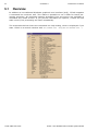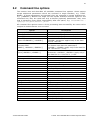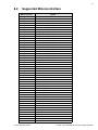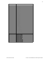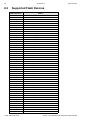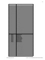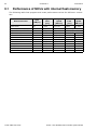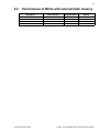
1
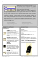
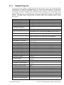
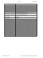
J-Flash ARM
Stand-alone Flash
programming software
Version 3.68
Manual Rev. 1
A product of SEGGER Microcontroller Systeme GmbH
2
Disclaimer
Specifications written in this document are believed to be accurate, but are not
guaranteed to be entirely free of error. The information in this manual is subject to
change for functional or performance improvements without notice. Please make sure
your manual is the latest edition. While the information herein is assumed to be
accurate, SEGGER MICROCONTROLLER SYSTEME GmbH (the manufacturer) assumes
no responsibility for any errors or omissions. The manufacturer makes and you
receive no warranties or conditions, express, implied, statutory or in any
communication with you. The manufacturer specifically disclaims any implied
warranty of merchantability or fitness for a particular purpose.
Copyright notice
You may not extract portions of this manual or modify the PDF file in any way without
the prior written permission of the manufacturer. The software described in this
document is furnished under a license and may only be used or copied in accordance
with the terms of such a license.
© 2007 SEGGER Microcontroller Systeme GmbH, Hilden / Germany
Trademarks
Names mentioned in this manual may be trademarks of their respective companies.
Brand and product names are trademarks or registered trademarks of their
respective holders.
Contact address
SEGGER Microcontroller Systeme GmbH
Heinrich-Hertz-Str. 5
D-40721 Hilden
Germany
Tel.+49 2103-2878-0
Fax.+49 2103-2878-28
Email: [email protected]
Internet: http://www.segger.com
Manual versions
This manual describes the latest software version. The version number of the
software can be found in the table ’Software versions’ later in this chapter. If any
error occurs, please inform us and we will assist you.
For further information on topics or routines not yet specified, please contact us.
Manual version
Date
3.68 Rev. 1
070508
3.66 Rev. 1
070322
3.46 Rev. 4
061222
3.46 Rev. 3
061124
3.46 Rev. 2
061121
3.46 Rev. 1
3.42 Rev. 1
060929
060912
J-Flash ARM User Guide
By
Explanation
Chapter "Installation" updated.
Chapter "Command Line Interface":
SK
* Section "Batch processing" added.
Various improvements.
Chapter "Target systems" updated.
SK
Chapter "Getting started" updated.
SK Sektion "About" and company description added.
O
Chapter "Performance" updated.
O
O
Chapter "Performance" updated.
O
TQ Update supported target devices.
TQ Update supported target devices.
© 2005 - 2007 SEGGER Microcontroller Systeme GmbH
3
Manual version
Date
By
3.36 Rev. 1
3.24 Rev. 1
060801
060530
3.00 Rev. 2
060116
3.00 Rev. 1
2.14
060112
051025
2.10
050926
2.04
050819
2.02
050808
2.00
050707
TQ
TQ
O
O
TQ
TQ
T
W
TQ
T
W
T
W
Explanation
Update supported target devices.
Update supported target devices.
Screenshots updated.
Nothing changed. Just a new software version.
Update supported target devices.
Added troubleshooting section.
Nothing changed. Just a new software version.
Command line added.
Initial Version
Software versions
Changes in the software are listed in the file "Release.html" shipped with the software.
J-Flash ARM User Guide
© 2005 - 2007 SEGGER Microcontroller Systeme GmbH
4
J-Flash ARM User Guide
© 2005 - 2007 SEGGER Microcontroller Systeme GmbH
5
About this document
Assumptions
This document assumes that you already have a solid knowledge of the following:
•
•
•
•
The software tools used for building your application (assembler, linker, C compiler)
The C programming language
The target processor
DOS command line.
If you feel that your knowledge of C is not sufficient, we recommend The C Programming Language by Kernighan and Richie (ISBN 0-13-1103628), which describes the
standard in C-programming and, in newer editions, also covers the ANSI C standard.
How to use this manual
This manual explains all the functions and macros that emFile offers. It assumes you
have a working knowledge of the C language. Knowledge of assembly programming
is not required.
Typographic conventions for syntax
This manual uses the following typographic conventions:
Style
Used for
Body
Body text.
Keyword
Text that you enter at the command-prompt or that appears on the
display (that is system functions, file- or pathnames).
Parameter
Parameters in API functions.
Sample
Sample code in program examples.
Reference
Reference to chapters, tables and figures or other documents.
GUIElement
Buttons, dialog boxes, menu names, menu commands.
Emphasis
Very important sections
Table 1.1: Typographic conventions
J-Flash ARM User Guide
© 2005 - 2007 SEGGER Microcontroller Systeme GmbH
6
SEGGER Microcontroller Systeme GmbH develops
and distributes software development tools and ANSI
C software components (middleware) for embedded
systems in several industries such as telecom, medical technology, consumer electronics, automotive
industry and industrial automation.
SEGGER’s intention is to cut software developmenttime for embedded applications by offering compact flexible and easy to use middleware,
allowing developers to concentrate on their application.
Our most popular products are emWin, a universal graphic software package for embedded applications, and embOS, a small yet efficent real-time kernel. emWin, written
entirely in ANSI C, can easily be used on any CPU and most any display. It is complemented by the available PC tools: Bitmap Converter, Font Converter, Simulator and
Viewer. embOS supports most 8/16/32-bit CPUs. Its small memory footprint makes it
suitable for single-chip applications.
Apart from its main focus on software tools, SEGGER developes and produces programming tools for flash microcontrollers, as well as J-Link, a JTAG emulator to assist in development, debugging and production, which has rapidly become the industry standard for
debug access to ARM cores.
Corporate Office:
http://www.segger.com
EMBEDDED SOFTWARE
(Middleware)
United States Office:
http://www.segger-us.com
SEGGER TOOLS
emWin
Flasher
Graphics software and GUI
emWin is designed to provide an efficient, processor- and display controller-independent graphical user
interface (GUI) for any application that
operates with a graphical display.
Starterkits, eval- and trial-versions are
available.
Flash programmer
Flash Programming tool primarily for microcontrollers.
J-Link
embOS
JTAG emulator with trace
USB driven JTAG interface for ARM cores with
Trace memory. supporting the ARM ETM (Embedded Trace Macrocell).
Real Time Operating System
embOS is an RTOS designed to offer
the benefits of a complete multitasking
system for hard real time applications
with minimal resources. The profiling
PC tool embOSView is included.
emFile
JTAG emulator for ARM cores
USB driven JTAG interface for ARM cores.
J-Trace
J-Link / J-Trace Related Software
Add-on software to be used with SEGGER’s industry standard JTAG emulator, this includes flash
programming software and flash breakpoints.
File system
emFile is an embedded file system with
FAT12, FAT16 and FAT32 support.
emFile has been optimized for minimum memory consumption in RAM and
ROM while maintaining high speed.
Various Device drivers, e.g. for NAND
and NOR flashes, SD/MMC and CompactFlash cards, are available.
emUSB
USB device stack
A USB stack designed to work on any
embedded system with a USB client
controller. Bulk communication and
most standard device classes are supported.
J-Flash ARM User Guide
© 2005 - 2007 SEGGER Microcontroller Systeme GmbH
7
Table of Contents
1 Introduction ......................................................................................................................9
1.1
1.1.1
1.2
1.3
1.3.1
1.3.2
What is J-Flash? ...................................................................................... 10
Features................................................................................................. 10
Assumptions ........................................................................................... 11
Requirements.......................................................................................... 12
Host ...................................................................................................... 12
Target.................................................................................................... 12
2 Installation of J-Flash .....................................................................................................13
2.1
2.1.1
Setup..................................................................................................... 14
What is included? .................................................................................... 14
3 Getting Started...............................................................................................................15
3.1
3.1.1
3.2
Using J-Flash for the First Time ................................................................. 16
Sample Projects ...................................................................................... 17
Menu structure........................................................................................ 19
4 Settings ..........................................................................................................................23
4.1
4.1.1
4.1.2
4.2
4.2.1
4.2.2
4.2.3
4.2.4
Global Settings........................................................................................ 24
Operation ............................................................................................... 24
Logging .................................................................................................. 24
Project Settings....................................................................................... 25
General Settings...................................................................................... 25
JTAG Settings ......................................................................................... 26
ARM Settings .......................................................................................... 27
Flash Settings ......................................................................................... 28
5 Command Line Interface................................................................................................31
5.1
5.2
5.2.1
5.2.2
Overview ................................................................................................ 32
Command line options.............................................................................. 33
Examples ............................................................................................... 34
Batch processing ..................................................................................... 35
6 Licensing........................................................................................................................37
6.1
6.2
6.2.1
6.2.2
General information about Licensing........................................................... 38
The licensing dialog ................................................................................. 38
The serial number.................................................................................... 38
License management ............................................................................... 39
7 Support ..........................................................................................................................41
7.1
7.1.1
7.1.2
7.2
Troubleshooting ...................................................................................... 42
General procedure ................................................................................... 42
Typical problems ..................................................................................... 42
Contacting support .................................................................................. 44
8 Target systems ..............................................................................................................45
8.1
8.2
Which devices can be programmed by J-Flash? ............................................ 46
Supported Microcontrollers........................................................................ 47
J-Flash ARM User Guide
© 2005 - 2007 SEGGER Microcontroller Systeme GmbH
8
8.3
Supported Flash Devices .......................................................................... 50
9 Performance ..................................................................................................................57
9.1
9.2
Performance of MCUs with internal flash memory ........................................ 58
Performance of MCUs with external flash memory........................................ 59
J-Flash ARM User Guide
© 2005 - 2007 SEGGER Microcontroller Systeme GmbH
9
Chapter 1
Introduction
The following chapter introduces J-Flash, highlights some of its features, and lists its
requirements on host and target systems.
J-Flash ARM User Guide
© 2005 - 2007 SEGGER Microcontroller Systeme GmbH
10
CHAPTER 1
1.1
Introduction
What is J-Flash?
J-Flash is a stand-alone flash programming software for PCs running Microsoft Windows. It has an intuitive user interface and makes programming flash devices convenient. J-Flash requires a J-Link, JTAG emulator for ARM cores, to interface to the
hardware. It is able to program internal and external flash at very high speeds,
upwards of 200 kB/sec depending on the chip. J-Flash has an approximate blank
check speed of 16 MB/sec. Another notable feature is smart read back, which only
transfers non-blank portions of the flash, increasing the speed of read back greatly.
These features along with its ability to work with any ARM7 or ARM9 chip makes it a
great solution for most projects.
1.1.1
•
•
•
•
•
•
•
•
•
•
Features
Any ARM7/ARM9 core supported, including thumb mode.
ARM microcontroller (internal flash) support.
Support for most external flash chips (see chapter “Target systems” on page 45
for a list of supported devices).
High speed programming: up to 200 kB/sec* (depending on flash device).
Very high speed blank check: approximately 16 MB/sec (depending on the chip).
Smart read back: only non-blank portions of flash are transferred and saved.
Free evaluation licenses available.
Verbose logging of all communication.
.hex, .mot, .srec, and .bin support.
Intuitive user interface.
* = Measured with J-Link ARM Rev.5 in DCC mode
1.2
Assumptions
This user manual assumes that you already possess working knowledge of the J-Link
device. If you feel that your knowledge of J-Link is not sufficient, we recommend the
J-Link manual, which describes the device and its use in detail.
1.3
Requirements
1.3.1
Host
J-Flash requires a PC running Microsoft Windows 2000 or Windows XP with a free USB
port dedicated for a J-Link. A network connection is required only if you want to use
J-Flash together with a remote J-Link server.
1.3.2
Target
A JTAG interface must be available on the target device to establish the connection
with the host system. A network connection must be available if and only if it is
desired to connect to the J-Link through the J-Link Server from a remote system.
J-Flash ARM User Guide
© 2005 - 2007 SEGGER Microcontroller Systeme GmbH
13
Chapter 2
Installation of J-Flash
The following chapter describes how to successfully install J-Flash on your host
system.
J-Flash ARM User Guide
© 2005 - 2007 SEGGER Microcontroller Systeme GmbH
14
CHAPTER 2
2.1
Installation of J-Flash
Setup
The J-Link setup procedure required in order to work with the J-Flash is described in
chapter 2 of the J-Link / J-Trace User Guide. The J-Link User Guide is part of the JLink software package which is available for download under www.segger.com.
2.1.1
What is included?
The following table shows the contents of all subdirectories of the J-Link ARM
software and documentation pack with regard to J-Flash:
Directory
Contents
.
The J-Flash application. Please refer to the J-Link manual for more information about the other J-Link related
tools.
.\Doc
Contains the J-Flash documentation and the other J-Link
related manuals.
.\ETC\JFlash\
Two *.csv files for the J-Flash internal management of
supported MCU’s und flash chips.
.\Sample\JFlash\ProjectFiles\
Contains sample projects with good default settings
(see section “Sample Projects” on page 17 for further
details).
J-Flash ARM User Guide
© 2005 - 2007 SEGGER Microcontroller Systeme GmbH
15
Chapter 3
Getting Started
This chapter presents an introduction to J-Flash. It provides an overview of the
included sample projects and describes J-Flash’s menu structure in detail.
J-Flash ARM User Guide
© 2005 - 2007 SEGGER Microcontroller Systeme GmbH
16
CHAPTER 3
3.1
Getting Started
Using J-Flash for the First Time
Start J-Flash from the Windows Start menu. J-Flash’s main window will apear, which
contains a log window at the bottom and the Project window of a default project on
the left. The application log will initially display:
•
•
•
•
•
The
The
The
The
The
version and time of compilation for the J-Flash application.
version and time of compilation for the J-Link DLL.
number of supported flash devices.
number of supported MCU devices.
location of the default project.
The Project window contains an overview of the current project settings (initially JFlash opens a default project).
J-Flash main window (as of version 2.00).
J-Flash ARM User Guide
© 2005 - 2007 SEGGER Microcontroller Systeme GmbH
17
3.1.1
Sample Projects
If you are new to J-Flash, it might be a good idea to open one of our sample projects
to familiarize yourself with the application. You find those project files in the Projects
subdirectory of J-Flash’s installation directory. Once you have opened a project file,
the project window contains the relevant project settings, e.g. chip type, clock
speed, RAM size etc. The settings are known to be good defaults for the respective
devices. You may then continue to open your own data files to actually program your
device. The table below contains the included project files together with a short
description.
Project
ADuC7020.jflash
ADuC7030.jflash
ADuC7032.jflash
ADuC7229.jflash
AT91FR40162.jflash
AT91M55800A.jflash
AT91R40008_AT91EB40A.jfl
ash
AT91RM9200_CSB337.jflas
h
AT91RM9200_CSB637.jflas
h
AT91RM9200_EK.jflash
AT91SAM7A1_EK.jflash
AT91SAM7A3.jflash
AT91SAM7S32.jflash
AT91SAM7S64.jflash
AT91SAM7S128.jflash
AT91SAM7S256.jflash
AT91SAM7SE512.jflash
AT91SAM7X128.jflash
AT91SAM7X256.jflash
DragonballMX1.jflash
Evaluator7T.jflash
LH75411.jflash
LH79520_LogicPD.jflash
LH79524_LogicPD.jflash
LH7A40x_LogicPD.jflash
LPC2103.jflash
LPC2106.jflash
LPC2129_MCB2100.jflash
LPC2138.jflash
LPC2148.jflash
LPC2290.jflash
LPC2294.jflash
LPC2294_PhyCORE.jflash
J-Flash ARM User Guide
Description
Analog Devices ADuC7020 with internal flash memory
Analog Devices ADuC7030 with internal flash memory
Analog Devices ADuC7032 with internal flash memory
Analog Devices ADuC7229 with internal flash memory
AT91FR40162 with internal AT49BV1614A flash memory
AT91M55800 with Am29LV320DT flash memory
AT91R40008 with external AT91EB40A flash memory
Cogent CSB337 eval. board with AT91RM9200
Cogent CSB637 eval. board with AT91RM9200
Atmel AT91RM9200 eval. board
Atmel AT91SAM7A1 eval. board with CFI compliant
flash memory
Atmel AT91SAM7A3 with internal flash memory
AT91SAM7S-EK eval. board with SAM7S32
AT91SAM7S-EK eval. board with SAM7S64
AT91SAM7S-EK eval. board with SAM7S128
AT91SAM7S-EK eval. board with SAM7S256
AT91SAM7SE-EK eval. board with SAM7SE512
AT91SAM7X-EK eval. board with SAM7X128
AT91SAM7X-EK eval. board with SAM7X256
DragonballMX1 eval. board with ST M29W400BB
Evaluator7T eval. board with SST39LF/VF400A flash
memory
Sharp LH75411 with Macronix MX29LV320AB flash
memory
Sharp LH79520 with Intel 28F640J3 flash memory
Sharp LH79524 with Sharp LH28F128SPHTD flash
memory
Sharp LH7A40x with Intel 28F640J3 flash memory (2
chips)
NXP LPC2103 with internal flash memory
NXP LPC2106 with internal flash memory
Keil MCB2100 eval. board with NXP LPC2129
NXP LPC2138 with internal flash memory
NXP LPC2148 with internal flash memory
NXP LPC2290 with internal flash memory
NXP LPC2294 with internal flash memory
NXP LPC2294 with external Am29DL800BT flash memory
© 2005 - 2007 SEGGER Microcontroller Systeme GmbH
18
CHAPTER 3
Project
LPC2366.jflash
LPC2378.jflash
MAC7111.jflash
ML67Q4050.jflash
ML67Q4051.jflash
ML67Q4060.jflash
ML67Q4061.jflash
NS7520_CC7U_352.jflash
NS7520_CC7U_355.jflash
NS9360.jflash
NS9750.jflash
PCF87750.jflash
PXA255_CSB625.jflash
S3F445HX.jflash
SJA2010HL.jflash
SJA2510HL.jflash
SocLitePlus.jflash
STR710.jflash
STR711.jflash
STR712.jflash
STR730.jflash
STR750.jflash
STR912.jflash
TMS470R1A64.jflash
TMS470R1A128.jflash
TMS470R1A256.jflash
TMS470R1A288.jflash
TMS470R1B1M.jflash
TMS470R1VF689.jflash
J-Flash ARM User Guide
Getting Started
Description
NXP LPC2366 with internal flash memory
NXP LPC2378 with internal flash memory
Freescale MAC7111LC eval. board with internal flash
OKI ML67Q4050 with internal flash memory
OKI ML67Q4051 with internal flash memory
OKI ML67Q4060 with internal flash memory
OKI ML67Q4061 with internal flash memory
Digi ConnectCore7U with NetSilicon NS7520 and external Fujitsu MBM29LV650U flash
Digi ConnectCore7U with NetSilicon NS7520 and external AMD Am29LV160BB flash
NetSilicon NS9360 with external AM29LV160DB flash
(2 chips)
NetSilicon NS9750 with Atmel AT49BV322A flash
memory
NXP PCF87750 with internal flash memory
Intel XScale PXA255 with external flash memory
Samsung S3F445HX with internal flash memory
NXP SJA2010 with internal flash memory
NXP SJA2510 with internal flash memory
ST STR710FZ2T6 with internal flash memory
ST STR711FR2T6 with internal flash memory
ST STR712FR2T6 with internal flash memory
ST STR730FZ2 with internal flash memory
ST STR750FV2 with internal flash memory
ST STR912FM44 with internal flash memory
TI TMS470R1A64 with internal flash memory
TI TMS470R1A128 with internal flash memory
TI TMS470R1A256 with internal flash memory
TI TMS470R1A288 with internal flash memory
TI TMS470R1B1M with internal flash memory
TI TMS470R1VF689 with internal flash memory
© 2005 - 2007 SEGGER Microcontroller Systeme GmbH
19
3.2
Menu structure
The main window of J-Flash contains seven drop-down menus (File, Edit, View,
Target, Options, Window, Help). Any option within these drop-down menus that is
followed by a three period ellipsis (...), is an option that requires more information
before proceeding.
File menu elements
Command
Open...
Merge
Save
Save As...
New Project
Open Project...
Save Project
Save Project As...
Close Project
Export Setup File...
Recent Files
>
Recent Projects >
Exit
Description
Opens a data file that may be used to flash the target
device. The data file must be an Intel HEX file, a Motorola S
file, or a Binary file (.hex, .mot, .srec, or .bin).
Merges two data files (.hex, .mot, .srec, or .bin).
Saves the data file that currently has focus.
Saves the data file that currently has focus using the name
and location given.
Creates a new project using the default settings.
Opens a J-Flash project file. Note that only one project file
may be open at a time. Opening a project will close any
other project currently open.
Saves a J-Flash project file.
Saves a J-Flash project file using the name and location
given.
Closes a J-Flash project file.
Exports a file that can be used to setup the J-Link. Please
refer to the J-Link documentation for more information
regarding J-Link setup files.
Contains a list of the most recently open data files.
Contains a list of the most recently open project files.
Exits the J-Flash application.
Edit menu elements
Command
Relocate...
Delete range...
Eliminate blank
areas...
Description
Relocates the start of the data file to the supplied hex offset
from the current start location.
Deletes a range of values from the data file, starting and
ending at given addresses. The End address must be
greater than the Start address otherwise nothing will be
done.
Eliminates blank regions within the data file.
View menu elements
Command
Log
Project
J-Flash ARM User Guide
Description
Opens and/or brings the log window to the active window.
Opens and/or brings the project window to the active window.
© 2005 - 2007 SEGGER Microcontroller Systeme GmbH
20
CHAPTER 3
Getting Started
Target menu elements
Command
Connect
Disconnect
Show CFI info...
Lock/Unlock sectors >
Secure chip
Unsecure chip
Check blank
Fill with zero
Erase sectors
Erase chip
Program
Program & Verify
Auto
Test >
Verify
J-Flash ARM User Guide
Description
Creates a connection through the J-Link using the configuration options set in the Project settings... of the Options
drop-down menu.
Disconnects a current connection that has been made
through the J-Link.
Reads the CFI query information of a CFI compliant flash
device.
Sectors may be locked and unlocked. The soft lock and soft
unlock work on a software only basis for those sectors that
have been selected on the Flash tab of the Project Settings... found in the Options drop-down menu. If the software locks a sector with soft lock, it can easily be unlocked
using the soft unlock feature. The hard lock and hard unlock
work on a hardware only basis. If a sector is locked using
the hard lock command, it can only be unlocked through
hardware support. For example, some flash devices have a
special PIN that must be set high or low to allow an unlock
command.
Secures the MCU.
Unsecures the MCU.
Checks flash to see if it is empty.
Fills all selected flash sectors with zero. Some flash chips
need this before erasing them.
Erases all selected flash sectors.
Erases the entire chip.
Programs the chip using the currently active data file.
Programs the chip using the currently active data file and
then verifies that it was written successfully.
The Auto command performs a sequence of steps. It connects to the device, erases sectors and programs the chip
using the currently active data file before the written data is
finally verified. The range of sectors to be erased can be
configured through the Flash tab of the Project settings dialog and through the Global settings dialog. See chapter
“Settings” on page 23 for further details.
Two test functions are implementet "Generates test data"
generates data which can be used to test if the flash can be
programmed correctly. The size of the gerated data file can
be defined.
"Tests up/download speed" writes data of an specified size
to an defined address, reads the written data back and
measures the up- and download speed.
Verifies the data found on the chip with the data file.
© 2005 - 2007 SEGGER Microcontroller Systeme GmbH
21
Command
VerifyCRC >
Read back >
Start Application
Description
Verifies the CRC. There are three ways in which the CRC can
be verified.
"Affected sectors" verifies the CRC of the affected sectors.
"Selected sectors" verifies the CRC of the selected sectors.
"Entire chip" verifies the CRC of the entire chip.
Reads back the data found on the chip and creates a new
data file to store this information. There are three ways in
which the data can be read back. The Selected sectors identified on the Flash tab of the Project Settings... found in the
Options drop-down menu may be read back. The Entire chip
may be read back. A specified Range... may be read back.
Starts the application found on the chip.
Options menu elements
Command
Project settings...
Global settings...
Description
Location of the project settings that are displayed in the
snapshot view found in the Project window of the J-Flash
application as well as various settings needed to locate the
J-Link and pass specified commands needed for chip initialization.
Settings that influence the general operation of J-Flash.
Window menu elements
Command
Cascade
Tile Horizontal
Tile Vertical
Description
Arranges all open windows, one above the other, with the
active window at the top.
Tiles the windows horizontally with the active window at the
top.
Tiles the windows vertically with the active window at the
left.
Help menu elements
Command
J-Flash ARM User’s
Guide
J-Link ARM User’s
Guide
Licenses...
About...
J-Flash ARM User Guide
Description
Shows this help file in a PDF viewer such as Adobe Reader.
Shows the J-Link ARM User’s Guide in a PDF viewer such as
Adobe Reader.
Shows a dialog with licensing information. The serial number of a connected J-Link may be read and licenses added
or removed.
J-Flash and company information.
© 2005 - 2007 SEGGER Microcontroller Systeme GmbH
22
J-Flash ARM User Guide
CHAPTER 3
Getting Started
© 2005 - 2007 SEGGER Microcontroller Systeme GmbH
23
Chapter 4
Settings
The following chapter provides an overview of the program settings. Both, general
and per project settings are considered.
J-Flash ARM User Guide
© 2005 - 2007 SEGGER Microcontroller Systeme GmbH
24
CHAPTER 4
4.1
Settings
Global Settings
Global settings are available from the Options menu in the main window.
4.1.1
Operation
You may define the behavior of some operations such as "Auto" or "Program & Verify".
Auto erase
You can specify if an automatically performed erasure during any program operation
is restricted to required sectors, selected sectors or not restricted at all. In the latter
case all sectors are erased.
Disconnect after each operation
If this option is checked, connection to the target will be closed at the end of each
operation.
Automatically unlock sectors
If this option is checked, all sectors affected by an erase or program operation will be
automatically unlocked if necessary.
Perform blank check
If this option is checked, a blank check is performed before any program operation to
check if the affected flash sectors are completely empty. The user will be asked to
erase the affected sectors if they are not empty.
Skip blank areas on read
If this option is checked, a blank check is performed before any read back operation
to check which flash areas need to be read back from target. This improves performance of read back operations since it minimizes the amount of data to be transferred via JTAG and USB.
4.1.2
Logging
You may set some logging options to customize the log output of J-Flash.
General log level
This specifies the log level of J-Flash. Increasing log levels result in more information
logged in the log window.
J-Flash ARM User Guide
© 2005 - 2007 SEGGER Microcontroller Systeme GmbH
25
Enable J-Link logfile
If this option is checked, you can specify a file name of the J-Link logfile. The J-Link
logfile differs from the log window output of J-Flash. It does not log J-Flash operations performed. Instead of that, it logs the J-Link ARM DLL API functions called from
within J-Flash.
4.2
Project Settings
Project settings are available from the Options menu in the main window or by using
the ALT-F7 keyboard shortcut.
4.2.1
General Settings
This dialog is used to choose the connection to J-Link. The J-Link can either be
connected directly over USB to the host system of J-Flash, or it can be connected
through the J-Link TCP/IP Server running on a remote system. Please refer to the JLink manual for more information regarding the operation of J-Link and J-Link TCP/IP
Server.
USB
If this option is checked, J-Flash will connect to J-Link over the USB port. You may
change the device number if you want to connect more than one J-Link to your PC.
The default device number is 0. For more information about how to use multiple JLinks on one PC, please see also the chapter "Working with J-Link" of the J-Link ARM
User’s Guide.
TCP/IP
If this option is checked, J-Flash will connect to J-Link via J-Link TCP/IP Server. You
have to specify the hostname of the remote system running the J-Link TCP/IP Server.
J-Flash ARM User Guide
© 2005 - 2007 SEGGER Microcontroller Systeme GmbH
26
CHAPTER 4
4.2.2
Settings
JTAG Settings
This dialog is used to configure the JTAG connection. You may change the JTAG speed
or configure a JTAG scan chain with multiple devices.
JTAG Speed
You can configure the JTAG speed used before and after initialization. The JTAG speed
before init is used to communicate with the target before and during execution of the
custom initialization sequence (described in chapter “ARM Settings” on page 27). The
JTAG speed after init is used to communicate after executing the custom initialization
sequence. This is useful if you have a target running at slow speed and you want to
set up a PLL in the initialization sequence.
You can choose between automatic speed recognition, adaptive clocking or fixed
JTAG speed. If you choose fixed JTAG speed you can select any value between 1kHz
and 12MHz.
For more information about the different types of JTAG speed please see the chapter
"Setup" of the J-Link ARM User’s Guide.
JTAG scan chain with multiple devices
This checkbox allows you to configure a JTAG scan chain with multiple devices on it.
In a scan chain configuration with multiple devices, the TCK and TMS lines of all JTAG
device are connected, while the TDI and TDO lines form a ring.
J-Flash ARM User Guide
© 2005 - 2007 SEGGER Microcontroller Systeme GmbH
27
The position of the device to connect with J-Flash is selected from the Position dropdown menu. The Instruction Register length (IRLen) of a device is defined by its
manufacturer. For ARM cores, the IRLen is always four, which is why the value of
IRLen is by default set to four times the position indicated. This works fine for ARM
only scan chains. However, if any non-ARM devices are introduced to the scan chain
the IRLen must be modified accordingly.
4.2.3
ARM Settings
This dialog allows the selection of microcontroller dependent settings.
Chip
J-Flash can be used to program both external or internal flash memory. In order to
use J-Flash with an external flash device, "Generic ARM7/ARM9" must be selected.
To program internal flash devices choose the respective microcontroller from the list.
If your microcontroller is not found on this list, please contact SEGGER as new microcontrollers are continuously being added.
Clock
In order to guarantee accurate operation of J-Flash you have to enter the correct
clock frequency in Hz of your MCU. If you set up a PLL or otherwise change the clock
frequency in the init sequence please take into account that you also have to modify
the value in this dialog.
Endian
The endianness of the chip is indicated through the Endian drop-down menu.
Check ARM core ID
If the core ID is known for the device to be programmed, it can be used to verify that
the device in communication via the J-Link is the intended device.
Use target RAM
You may enable the use of target RAM to speed up flash operations. To use the target
RAM, a start location in RAM and the amount of RAM to be used must be entered.
J-Flash ARM User Guide
© 2005 - 2007 SEGGER Microcontroller Systeme GmbH
28
CHAPTER 4
Settings
Enable DCC mode
DCC mode encompasses those features of halt mode and run mode debugging that in
most instances facilitate quicker communication. Consequently enabling DCC mode
results in improved performance. It is therefore suggested that DCC mode is enabled
unless there are communication difficulties.
Init sequence
Many microcontrollers require an initialization sequence for different reasons: When
powered on, the PLL may not be initialized, which means the chip is very slow or a
watchdog must be disabled manually. To use these chips you must first perform the
required initialization.
This dialog lets the user enter a custom initialization sequence using a predefined list
of operations. After choosing an operation and corresponding values to be associated
with the operation, a comment may be added to make it easier for others to determine its effect.
4.2.4
Flash Settings
This dialog is used to select and configure the flash device to operate with.
Base Address
You may enter the base address of the selected flash memory. The default value is 0.
Organization
You should select the buswidth and the number of flash chips connected to the
address and data bus of the MCU
J-Flash ARM User Guide
© 2005 - 2007 SEGGER Microcontroller Systeme GmbH
29
Select flash device
After invoking this button a table will be presented. The table may be filtered using
the manufacturer name. The chip and its attributes (manufacturer name, device
name, size, number of sectors, eight bit identifier, sixteen bit identifier, bus width)
must be selected from this table. If the flash chip is not found please contact SEGGER, as devices are continuously being added to this list.
ID checking
There are two other check boxes that are of interest in this subsection which are
"Check manufacturer flash Id" and "Check product flash Id". These check boxes
should be selected to confirm the type of device that is in communication with JFlash.
Sector selection
The final section of this dialog indicates the sectors to be acted upon, whether they
are to be cleared, read back, or written. An individual or series of sectors may be
selected from the predetermined valid range.
J-Flash ARM User Guide
© 2005 - 2007 SEGGER Microcontroller Systeme GmbH
30
J-Flash ARM User Guide
CHAPTER 4
Settings
© 2005 - 2007 SEGGER Microcontroller Systeme GmbH
31
Chapter 5
Command Line Interface
This chapter describes the J-Flash command line interface. The command line allows
using J-Flash in batch processing mode and other advanced uses.
J-Flash ARM User Guide
© 2005 - 2007 SEGGER Microcontroller Systeme GmbH
32
5.1
CHAPTER 5
Command Line Interface
Overview
In addition to its traditional Windows graphical user interface (GUI), J-Flash supports
a command line mode as well. This makes it possible to use J-Flash for batch processing purposes. All important options accessible from the menus are available in
command line mode as well. If you provide command line options, J-Flash will still
start its GUI, but processing will start immediately.
The screenshot below shows the command line help dialog, which is displayed if you
start J-Flash in a console window with JFlashARM.exe -help or JFlashARM.exe -?
J-Flash ARM User Guide
© 2005 - 2007 SEGGER Microcontroller Systeme GmbH
33
5.2
Command line options
This section lists and describes all available command line options. Some options
accept additional parameters which are enclosed in angle brackets, e.g. <FILENAME>. If these parameters are optional they are enclosed in square brackets too,
e.g. [<SADDR>]. Neither the angel nor the square brackets must be typed on the
command line, they are used here only to denote (optional) parameters. Also, note
that a parameter must follow immediately after the option, e.g. JFlashARM.exe openprjC:\Projects\Default.jflash.
All command line options return 0 if the processing was successfully. An return value
unequal 0 means that an error occured.
Option
-openprj<FILENAME>
-saveprjas<FILENAME>
-saveprj
-open<FILENAME>[,<SADDR>]
-saveas<FILENAME>[,<SADDR>,<EADDR>]
-save[<SADDR>,<EADDR>]
-relocate<OFFSET>
-delrange<SADDR>,<EADDR>
-eliminate
-connect
-disconnect
-softlock
-softunlock
-hardlock
-hardunlock
-checkblank
-erasesectors
-erasechip
-programverify
-program
-auto
-readsectors
-readchip
-readrange<SADDR>,<EADDR>
-startapp
-exit
-help
-?
J-Flash ARM User Guide
Description
Open an existing project file.
Save the current project in the specified file.
Save the current project.
Open a data file. Please note that the
<SADDR> parameter applies only if the data
file is a *.bin file.
Save the current data file into the specified
file. Please note that the parameters
<SADDR>, <EADDR> apply only if the data file
is a *.bin file or *.c file.
Save the current data file. Please note that the
parameters <SADDR>,<EADDR> apply only if
the data file is a *.bin file or *.c file.
Relocate data by the given offset.
Delete data in the given range.
Eliminate blank areas in data file.
Connect to target.
Disconnect from target.
Lock (soft) selected sectors.
Unlock (soft) selected sectors.
Locks (hard) selected sectors.
Unlocks (hard) selected sectors.
Blank check target.
Erase selected sectors.
Erase the entire flash chip.
Program and verify target.
Program target.
Erase, program and verify target.
Read selected sectors.
Read entire flash chip.
Read specified range of target memory.
Start target application.
Exit J-Flash.
Display help dialog.
Display help dialog.
© 2005 - 2007 SEGGER Microcontroller Systeme GmbH
34
CHAPTER 5
5.2.1
Command Line Interface
Examples
Open a project and data file, start auto processing and exit
JFlashARM.exe -openprjC:\Projects\Default.jflash -openC:\Data\data.bin,0x100000
-auto -exit
Open a project file, read back selected sectors and write the data to disk
JFlashARM.exe -openprjC:\Projects\Default.jflash -readsectors
-saveasC:\Data\data.bin,0x100000,0x10FFFF
J-Flash ARM User Guide
© 2005 - 2007 SEGGER Microcontroller Systeme GmbH
35
5.2.2
Batch processing
J-Flash can be used for batch processing purposes. All important options are available in command line mode as well. If you provide command line options, J-Flash will
still start its GUI, but processing will start immediately.
The example batchfile displays a message, opens a project and a data file, starts
auto processing and closes J-Flash. The return value will be checked and in case of
an error an error message displayed.
Adapt the example according to the requirements of your project.
@ECHO OFF
ECHO Open a project and data file, start auto processing and exit
JFlashARM.exe -openprjC:\Projects\Default.jflash -openC:\Data\data.bin,0x100000 auto -exit
IF ERRORLEVEL 1 goto ERROR
goto END
:ERROR
ECHO J-Flash ARM:
pause
Error!
:END
Note, that every call of JFlashARM.exe has to completed with the -exit option, otherwise stops the execution of the batch file and the following commands will not be
processed.
J-Flash ARM User Guide
© 2005 - 2007 SEGGER Microcontroller Systeme GmbH
36
J-Flash ARM User Guide
CHAPTER 5
Command Line Interface
© 2005 - 2007 SEGGER Microcontroller Systeme GmbH
37
Chapter 6
Licensing
The following chapter provides an overview of J-Flash related licensing options.
J-Flash ARM User Guide
© 2005 - 2007 SEGGER Microcontroller Systeme GmbH
38
CHAPTER 6
6.1
Licensing
General information about Licensing
J-Flash may be installed on as many host machines as you want. Without a license
key you can still use J-Flash to open project files, read from connected devices, blank
check target memory, verify data files and so on. However to actually program
devices via J-Flash and J-link you are required to obtain a license key from us. A JFlash license is bound to the serial number of a J-Link. If you need a license key you
only have to tell us the serial number of your J-Link which allows us to send you a
proper key. Evaluation licenses which allow you to unlock the full potential of J-Flash
for a limited period of time are available. In any case you need to have a license key
for each J-Link you want to work with via J-Flash. The following sections describe
common operations with reference to handling license keys.
6.2
The licensing dialog
The licensing dialog will be displayed after selecting Licenses... from the Help menu
of the main window. It shows the available licenses and allows to add and remove
licenses as well.
6.2.1
The serial number
The licensing dialog contains a button Display serial number. J-Flash tries to read the
serial number of a connected J-Link if you press this button.
J-Flash ARM User Guide
© 2005 - 2007 SEGGER Microcontroller Systeme GmbH
39
6.2.2
License management
The licensing dialog contains buttons to add and remove license keys. After you
received a key from us, click on Add license to unlock J-Flash. Depending on the
license you requested you are free to use J-Flash either for an unlimited or limited
period of time. Enter the key into the Add license dialog and click OK to submit.
The licensing dialog will show the licenses together with their expiration date, the
serial number they are bound to and the feature that is licensed by the respective
key.
You may select individual license keys for removal. Click the Delete license button
after selecting the key you want to remove. The key is deleted immediately without
asking for confirmation and the licensed features become unavailable.
J-Flash ARM User Guide
© 2005 - 2007 SEGGER Microcontroller Systeme GmbH
40
J-Flash ARM User Guide
CHAPTER 6
Licensing
© 2005 - 2007 SEGGER Microcontroller Systeme GmbH
41
Chapter 7
Support
The following chapter provides information about how to contact our support.
J-Flash ARM User Guide
© 2005 - 2007 SEGGER Microcontroller Systeme GmbH
42
CHAPTER 7
7.1
Support
Troubleshooting
7.1.1
•
•
•
•
•
7.1.2
General procedure
Make sure your J-Link is working as expected. See the troubleshooting section in
the J-Link manual.
Ensure that the target hardware matches the project file settings. Pay special
attention to the following aspects:
- Init sequence
- Clock speed
- RAM address
- Flash base address
- MCU / Flash chip
- Flash organization
Try to program your target device using a sample project file if available. J-Flash
ships with an extensive number of project files for many target boards. See section “Sample Projects” on page 17 for a complete list of project files.
The JTAG clock frequency depends on several factors, e.g. cable length, target
board etc. Try setting the frequency to lower or higher values accordingly.
Make sure the flash memory is unlocked before programming or erasing.
Typical problems
Failed to connect
Meaning:
This error message is shown if any error occurs during the connection process.
Remedy:
First of all, make sure the target is actually connected to J-Link. Verify the correctness of the init sequence, check the JTAG speed, and ensure the correct flash type is
selected.
Programming / Erasing failed
Meaning:
The flash memory sector may be locked and programming or erasing the respective
memory section fails therefore.
Remedy:
Make sure the memory sector is unlocked before programming or erasing. J-Flash
provides a dedicated menu item for unlocking flash memory.
Timeout errors during programming
Meaning:
A timeout occurs if the target is too slow during DCC communication or the target
flash memory is too slow during programming.
Remedy:
Using smaller RAM block sizes may fix this problem.
Blank check failed
Meaning:
The target memory was not empty during blank check.
Remedy:
Erase target memory.
J-Flash ARM User Guide
© 2005 - 2007 SEGGER Microcontroller Systeme GmbH
43
RAM check failed
Meaning:
No RAM found at the specified RAM location.
Remedy:
Make sure a correct RAM address is specified in the project settings. See section
“ARM Settings” on page 27.
Unexpected core ID
Meaning:
The specified CPU core ID does not match with the one read from the target CPU.
Remedy:
Ensure the specified core ID is correct for the used target CPU. See section “ARM Settings” on page 27 for information about setting the core ID.
Unsupported flash type / bus width
Meaning:
The target flash memory or the bus organization is not yet supported.
Remedy:
Inform us about the flash type you want to use. SEGGER is constantly adding support
for new flash memory devices.
No matching RAMCode
Meaning:
There is no programming algorithm available for the selected target memory type.
Remedy:
Inform us about the flash type you want to use. SEGGER is constantly adding support
for new flash memory devices.
J-Flash ARM User Guide
© 2005 - 2007 SEGGER Microcontroller Systeme GmbH
44
CHAPTER 7
7.2
Support
Contacting support
If you experience a J-Flash related problem and the advices from the sections above
do not help you to solve it, you may contact our J-Flash support. In this case, please
provide us with the following information:
•
•
•
•
A detailed description of the problem.
The relevant log file and project file. In order to generate an expressive log file,
set the log level to "All messages" (see section “Global Settings” on page 24 for
information about changing the log level in J-Flash).
The relevant data file as a .hex or .mot file (if possible)
The processor and flash types used
Once we received this information we will try our best to solve the problem for you.
Our contact address is as follows:
SEGGER Microcontroller Systeme GmbH
Heinrich-Hertz-Str. 5
D-40721 Hilden
Germany
Tel.+49 2103-2878-0
Fax.+49 2103-2878-28
Email: [email protected]
Internet: http://www.segger.com
J-Flash ARM User Guide
© 2005 - 2007 SEGGER Microcontroller Systeme GmbH
45
Chapter 8
Target systems
The following chapter lists all supported flash devices and microcontrollers.
J-Flash ARM User Guide
© 2005 - 2007 SEGGER Microcontroller Systeme GmbH
46
8.1
CHAPTER 8
Target systems
Which devices can be programmed by J-Flash?
J-Flash can program external as well as internal flash. Any combination of ARM CPU
and external flash is supported if the flash chip is listed in section “Supported Flash
Devices” on page 50. Beside the listed flash chips is every CFI compliant chip supported. In addition, all types of flash interfacing are supported: 1x8bit, 2x8bit,
4x8bit, 1x16bit, 2x16bit, 1x32bit.
Regarding internal flash, J-Flash supports a wide range of microcontrollers. The next
section lists all supported micros.
If you need support for a chip or flash not listed in the tables below, do not hesitate
to contact us. Segger is constantly adding support for new devices. You may want to
request an updated list or have a look at www.segger.com for more up to date information.
J-Flash ARM User Guide
© 2005 - 2007 SEGGER Microcontroller Systeme GmbH
47
8.2
Supported Microcontrollers
Manufacturer
Analog Devices
Analog Devices
Analog Devices
Analog Devices
Analog Devices
Analog Devices
Analog Devices
Analog Devices
Analog Devices
Analog Devices
Analog Devices
Analog Devices
Analog Devices
Analog Devices
Analog Devices
Analog Devices
Analog Devices
Analog Devices
Analog Devices
Analog Devices
Analog Devices
Analog Devices
Analog Devices
Analog Devices
Analog Devices
Analog Devices
Analog Devices
Atmel
Atmel
Atmel
Atmel
Atmel
Atmel
Atmel
Atmel
Atmel
Atmel
Atmel
Atmel
Freescale
Freescale
Freescale
Freescale
Freescale
Freescale
Freescale
Freescale
Freescale
Freescale
J-Flash ARM User Guide
Name
ADuC7020x62 (to E)
ADuC7020x62 (G on)
ADuC7021x32 (to E)
ADuC7021x32 (G on)
ADuC7021x62 (to E)
ADuC7021x62 (G on)
ADuC7022x32 (to E)
ADuC7022x32 (G on)
ADuC7022x62 (to E)
ADuC7022x62 (G on)
ADuC7024x62 (to E)
ADuC7024x62 (G on)
ADuC7025x62 (to E)
ADuC7025x62 (G on)
ADuC7025x32 (to E)
ADuC7025x32 (G on)
ADuC7026x62 (to E)
ADuC7026x62 (G on)
ADuC7027x62 (to E)
ADuC7027x62 (G on)
ADuC7030
ADuC7031
ADuC7032
ADuC7033
ADuC7128
ADuC7129
ADuC7229x126
AT91SAM7A3
AT91SAM7S32
AT91SAM7S321
AT91SAM7S64
AT91SAM7S128
AT91SAM7S256
AT91SAM7S512
AT91SAM7SE32
AT91SAM7SE256
AT91SAM7SE512
AT91SAM7X128
AT91SAM7X256
MAC7101
MAC7106
MAC7111
MAC7112
MAC7116
MAC7121
MAC7122
MAC7126
MAC7131
MAC7136
© 2005 - 2007 SEGGER Microcontroller Systeme GmbH
48
CHAPTER 8
Manufacturer
Freescale
Freescale
OKI
OKI
OKI
OKI
NXP
NXP
NXP
NXP
NXP
NXP
NXP
NXP
NXP
NXP
NXP
NXP
NXP
NXP
NXP
NXP
NXP
NXP
NXP
NXP
NXP
NXP
NXP
NXP
NXP
NXP
NXP
NXP
NXP
NXP
NXP
NXP
Samsung
ST
ST
ST
ST
ST
ST
ST
ST
ST
ST
ST
ST
J-Flash ARM User Guide
Target systems
Name
MAC7141
MAC7142
ML67Q4050
ML67Q4051
ML67Q4060
ML67Q4061
LPC2101
LPC2102
LPC2103
LPC2104
LPC2105
LPC2106
LPC2114
LPC2119
LPC2124
LPC2129
LPC2131
LPC2132
LPC2134
LPC2136
LPC2138
LPC2141
LPC2142
LPC2144
LPC2146
LPC2148
LPC2194
LPC2212
LPC2214
LPC2292
LPC2294
LPC2364
LPC2366
LPC2368
LPC2378
PCF87750
SJA2010
SJA2510
S3F445HX
STR710FZ1
STR710FZ2
STR711FR0
STR711FR1
STR711FR2
STR712FR0
STR712FR1
STR712FR2
STR715FR0
STR730FZ1
STR730FZ2
STR731FV0
© 2005 - 2007 SEGGER Microcontroller Systeme GmbH
49
Manufacturer
ST
ST
ST
ST
ST
ST
ST
ST
ST
ST
ST
ST
ST
ST
ST
ST
ST
ST
ST
ST
ST
ST
ST
ST
ST
ST
TI
TI
TI
TI
TI
TI
TI
TI
TI
TI
TI
J-Flash ARM User Guide
Name
STR731FV1
STR731FV2
STR735FZ1
STR735FZ2
STR736FV0
STR736FV1
STR736FV2
STR750FV0
STR750FV1
STR750FV2
STR751FR0
STR751FR1
STR751FR2
STR752FR0
STR752FR1
STR752FR2
STR755FR0
STR755FR1
STR755FR2
STR755FV0
STR755FV1
STR755FV2
STR911FM32
STR911FM44
STR912FM32
STR912FM44
TMS470R1A64
TMS470R1A128
TMS470R1A256
TMS470R1A288
TMS470R1A384
TMS470R1B512
TMS470R1B768
TMS470R1B1M
TMS470R1VF288
TMS470R1VF688
TMS470R1VF689
© 2005 - 2007 SEGGER Microcontroller Systeme GmbH
50
8.3
CHAPTER 8
Target systems
Supported Flash Devices
Manufacturer
AMD
AMD
AMD
AMD
AMD
AMD
AMD
AMD
AMD
AMD
AMD
AMD
AMD
AMD
AMD
AMD
AMD
AMD
AMD
AMD
AMD
AMD
AMD
AMD
AMD
AMD
AMD
AMD
AMD
AMD
AMD
AMD
AMD
AMD
AMD
AMD
AMD
AMD
AMD
AMD
AMD
AMD
AMD
AMD
AMD
AMD
AMD
AMD
AMD
J-Flash ARM User Guide
Name
Am29DL161DB
Am29DL161DT
Am29DL162DB
Am29DL162DT
Am29DL163DB
Am29DL163DT
Am29DL164DB
Am29DL164DT
Am29DL322DB/GB
Am29DL322DT/GT
Am29DL323DB/GB
Am29DL323DT/GT
Am29DL324DB/GB
Am29DL324DT/GT
Am29DL400BB
Am29DL400BT
Am29DL800BB
Am29DL800BT
Am29DS323DB
Am29DS323DT
Am29F100B
Am29F100T
Am29F400BB
Am29F400BT
Am29F800BB
Am29F800BT
Am29LV001BB
Am29LV001BT
Am29LV002BB
Am29LV002BT
Am29LV004BB
Am29LV004BT
Am29LV033C
Am29LV033MU
Am29LV116DB
Am29LV116DT
Am29LV160BB
Am29LV160BT
Am29LV160DB
Am29LV160DT
Am29LV200BB
Am29LV200BT
Am29LV320DB
Am29LV320DT
Am29LV400BB
Am29LV400BT
Am29LV640D
Am29LV641D
Am29LV800BB
© 2005 - 2007 SEGGER Microcontroller Systeme GmbH
51
Manufacturer
AMD
AMD
AMD
AMIC
AMIC
Atmel
Atmel
Atmel
Atmel
Atmel
Atmel
Atmel
Atmel
Atmel
Atmel
Atmel
Atmel
Atmel
Atmel
Atmel
Atmel
Atmel
Atmel
Atmel
Atmel
Atmel
Atmel
Atmel
Atmel
Atmel
Atmel
Atmel
Atmel
Atmel
Atmel
Atmel
Atmel
Atmel
Atmel
Atmel
Atmel
Atmel
Atmel
Atmel
Atmel
Atmel
Atmel
Atmel
Atmel
Atmel
Atmel
J-Flash ARM User Guide
Name
Am29LV800BT
Am29SL800DB
Am29SL800DT
A29L400B
A29L400T
AT29BV010A
AT29BV020
AT29BV040
AT29BV040A
AT29C010A
AT29C020
AT29C040
AT29C040A
AT29C1024
AT29C256
AT29C257
AT29C512
AT29LV010A
AT29LV020
AT29LV040
AT29LV040A
AT29LV1024
AT29LV256
AT29LV512
AT49BN6416
AT49BN6416T
AT49BV001A
AT49BV001AN
AT49BV001ANT
AT49BV001AT
AT49BV002
AT49BV002A
AT49BV002AN
AT49BV002ANT
AT49BV002AT
AT49BV002N
AT49BV002NT
AT49BV002T
AT49BV040A
AT49BV1024A
AT49BV1604
AT49BV1604A
AT49BV1604AT
AT49BV1604T
AT49BV160C
AT49BV160CT
AT49BV160D
AT49BV160DT
AT49BV163D
AT49BV163DT
AT49BV1614
© 2005 - 2007 SEGGER Microcontroller Systeme GmbH
52
CHAPTER 8
Manufacturer
Atmel
Atmel
Atmel
Atmel
Atmel
Atmel
Atmel
Atmel
Atmel
Atmel
Atmel
Atmel
Atmel
Atmel
Atmel
Atmel
Atmel
Atmel
Atmel
Atmel
Atmel
Atmel
Atmel
Atmel
Atmel
Atmel
Atmel
Atmel
Atmel
Atmel
Atmel
Atmel
Atmel
Atmel
Atmel
Atmel
Atmel
Atmel
Atmel
Atmel
Atmel
Atmel
Atmel
Atmel
Atmel
Atmel
Atmel
Atmel
Atmel
Atmel
Atmel
J-Flash ARM User Guide
Target systems
Name
AT49BV1614A
AT49BV1614AT
AT49BV1614T
AT49BV162A
AT49BV162AT
AT49BV2048A
AT49BV320C
AT49BV320CT
AT49BV320D
AT49BV320DT
AT49BV322A
AT49BV322AT
AT49BV322D
AT49BV322DT
AT49BV4096A
AT49BV512
AT49BV640
AT49BV640T
AT49BV642D
AT49BV642DT
AT49BV6416
AT49BV6416T
AT49BV802A
AT49BV802AT
AT49F001A
AT49F001AN
AT49F001ANT
AT49F001AT
AT49F002A
AT49F002AN
AT49F002ANT
AT49F002AT
AT49F040A
AT49F1024
AT49F1024A
AT49F1025
AT49F2048A
AT49F4096A
AT49F512
AT49LV002
AT49LV002N
AT49LV002NT
AT49LV002T
AT49LV1024
AT49LV1024A
AT49LV1614A
AT49LV1614AT
AT49LV2048A
AT49LV4096A
AT49SN3208
AT49SN3208T
© 2005 - 2007 SEGGER Microcontroller Systeme GmbH
53
Manufacturer
Atmel
Atmel
Atmel
Atmel
Atmel
Atmel
Fujitsu
Fujitsu
Fujitsu
Intel
Intel
Intel
Intel
Intel
Intel
Intel
Intel
Intel
Intel
Intel
Intel
Intel
Intel
Intel
Intel
Intel
Intel
Intel
Intel
Intel
Intel
Intel
Intel
Intel
Intel
Intel
Intel
Intel
Intel
Intel
Intel
Intel
Intel
Intel
Intel
Intel
Intel
Intel
Intel
Intel
Intel
J-Flash ARM User Guide
Name
AT49SN6416
AT49SN6416T
AT49SV322A
AT49SV322AT
AT49SV802A
AT49SV802AT
MBM29DL322BE/BD
MBM29DL322TE/TD
MBM29LV650U
28F004B3B
28F004B3T
28F008B3B
28F008B3T
28F016B3B
28F016B3T
28F128J3
28F128K18
28F128K3
28F128P30B
28F128P30T
28F128W18B
28F128W18T
28F160B3B
28F160B3T
28F160C3B
28F160C3T
28F256J3
28F256K18
28F256K3
28F256P30B
28F256P30T
28F320B3B
28F320B3T
28F320C3B
28F320C3T
28F320J3
28F320W18B
28F320W18T
28F400B3B
28F400B3T
28F640B3B
28F640B3T
28F640C3B
28F640C3T
28F640J3
28F640K18
28F640K3
28F640P30B
28F640P30T
28F640W18B
28F640W18T
© 2005 - 2007 SEGGER Microcontroller Systeme GmbH
54
CHAPTER 8
Manufacturer
Intel
Intel
Intel
Intel
Macronix
Macronix
Sharp
Sharp
Sharp
Sharp
Sharp
Sharp
Sharp
Sharp
Spansion
Spansion
Spansion
Spansion
Spansion
Spansion
Spansion
Spansion
Spansion
Spansion
Spansion
Spansion
Spansion
Spansion
Spansion
Spansion
Spansion
Spansion
Spansion
Spansion
Spansion
Spansion
Spansion
Spansion
Spansion
Spansion
Spansion
Spansion
Spansion
Spansion
Spansion
Spansion
Spansion
Spansion
Spansion
Spansion
Spansion
J-Flash ARM User Guide
Target systems
Name
28F800B3B
28F800B3T
28F800C3B
28F800C3T
MX29LV320AB
MX29LV320AT
LH28F128BFHED
LH28F128BFHT
LH28F128SPHTD
LH28F640BFHE-PBTL
LH28F640BFHE-PTTL
LH28F640BFHG-PBTL
LH28F640BFHG-PTTL
LHF00L29
S29AL016Dxxxxx01
S29AL016Dxxxxx02
S29AL032Dxxxxx00
S29AL032Dxxxxx03
S29AL032Dxxxxx04
S29AL032Hxxxxx01
S29AL032Hxxxxx02
S29AL032Hxxxxx21
S29AL032Hxxxxx22
S29AL032Hxxxxx31
S29AL032Hxxxxx32
S29AL032Hxxxxx41
S29AL032Hxxxxx42
S29GL032MxR0
S29GL032MxR1
S29GL032MxR2
S29GL032MxR3
S29GL032MxR4
S29GL032MxR5
S29GL032MxR6
S29GL064MxR0
S29GL064MxR1
S29GL064MxR2
S29GL064MxR3
S29GL064MxR4
S29GL064MxR5
S29GL064MxR6
S29GL064MxR7
S29GL064MxR8
S29GL064MxR9
S29GL128M
S29GL128N
S29GL256M
S29GL256N
S29GL512N
S71PL032J
S71PL064J
© 2005 - 2007 SEGGER Microcontroller Systeme GmbH
55
Manufacturer
Spansion
SST
SST
SST
SST
SST
SST
SST
SST
SST
SST
SST
SST
SST
SST
ST
ST
ST
ST
ST
ST
ST
ST
ST
ST
ST
ST
ST
ST
ST
ST
ST
ST
ST
ST
ST
ST
ST
ST
ST
ST
ST
ST
ST
ST
ST
ST
ST
Toshiba
Toshiba
J-Flash ARM User Guide
Name
S71PL127J
SST39LF200A
SST39LF400A
SST39LF800A
SST39VF1601
SST39VF1602
SST39VF200A
SST39VF3201
SST39VF3202
SST39VF400A
SST39VF6401
SST39VF6401B
SST39VF6402
SST39VF6402B
SST39VF800A
M28W320FCB
M28W320FCT
M28W320FSB
M28W320FST
M28W640ECB
M28W640ECT
M28W640FCB
M28W640FCT
M28W640FSB
M28W640FST
M29DW128F
M29DW323DB
M29DW323DT
M29DW324DB
M29DW324DT
M29DW640D
M29W160DB
M29W160DT
M29W160EB
M29W160ET
M29W200BB
M29W200BT
M29W320DB
M29W320DT
M29W400BB
M29W400BT
M29W400DB
M29W400DT
M29W640DB
M29W640DT
M29W800DB
M29W800DT
M58LW064D
TC58FVB160
TC58FVT160
© 2005 - 2007 SEGGER Microcontroller Systeme GmbH
56
J-Flash ARM User Guide
CHAPTER 8
Target systems
© 2005 - 2007 SEGGER Microcontroller Systeme GmbH
57
Chapter 9
Performance
The following chapter lists programming performance of common flash devices and
microcontrollers.
J-Flash ARM User Guide
© 2005 - 2007 SEGGER Microcontroller Systeme GmbH
58
9.1
CHAPTER 9
Performance
Performance of MCUs with internal flash memory
The following table lists program and erase performance values for different controllers.
Microcontroller
Analog Devices
ADuC7020
Atmel AT91SAM7S64
Atmel AT91SAM7S256
NXP LPC2148
NXP LPC2138
NXP LPC2129 V1
NXP LPC2106
NXP LPC2129 V2
NXP LPC2294
ST STR711
ST STR912
TI TMS470R1B1M
J-Flash ARM User Guide
Size
[kByte]
Program
time
[sec]
Program
speed
[kB/sec]
Erase
Time
[sec]
Erase
speed
[kB/sec]
62
2.234
27.752
3.031
20.455
64
256
500
500
248
120
248
248
272
512
1024
3.235
6.734
3.953
3.906
1.828
0.948
1.797
1.875
4.890
7.000
10.953
19.783
38.016
126.486
128.008
135.667
126.582
138.007
132.266
55.623
73.142
93.490
- Not required
- Not required
12.312
40.610
12.312
40.610
7.812
31.746
6.875
17.454
7.750
32.000
7.812
31.746
9.703
28.032
9.375
54.613
18.359
55.776
© 2005 - 2007 SEGGER Microcontroller Systeme GmbH
59
9.2
Performance of MCUs with external flash memory
Hardware
Atmel AT91EB40
Cogent CSB337
NetSilicon NS9360
Logic LH7A400
J-Flash ARM User Guide
Flash device
Atmel AT49BV162A
Intel 28F640J3
AMD Am29LV160DB
Intel 28F640J3A120
Organization
1*16
1*16
2*16
2*16
Bits
Bits
Bits
Bits
Speed
105.025 kB/s
93.058 kB/s
185.171 kB/s
154.978 kB/s
© 2005 - 2007 SEGGER Microcontroller Systeme GmbH
60
J-Flash ARM User Guide
CHAPTER 9
Performance
© 2005 - 2007 SEGGER Microcontroller Systeme GmbH
61
Index
C
Contact address ................................... 2
F
Flash devices ......................................50
Flash, supported interfacing types ..........46
J
J-Link .................................................12
JTAG ............................................ 12, 26
M
Menu structure ....................................19
Microcontrollers ........................ 47, 58–59
P
Projects ..............................................17
S
Syntax, conventions used ...................... 5
J-Flash ARM User Guide
© 1997 - 2007 SEGGER Microcontroller Systeme GmbH
62
J-Flash ARM User Guide
Index
© 1997 - 2007 SEGGER Microcontroller Systeme GmbH