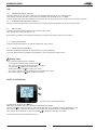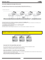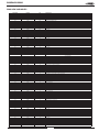
1
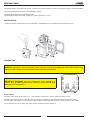
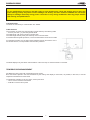
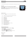
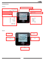
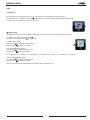
User manual
CLIMATIC™ 60
Providing indoor climate comfort
MUL46E-0413 04-2013
Original manual translation
TABLE OF CONTENTS
AQUALEAN
CONTROL MANUAL
DISPLAY DC60
INSTALLATION
2
CONNECTION
2
IMPORTANT WARNING
2
TEMPERATURE MEASUREMENT
3
CONFIGURATION
4
INITIALIZATION
5
SOFTWARE
5
UNIT RANGE & MODELS
5
BLOWER MANAGEMENT
5
COOL / HEAT / AUTO MODE SELECTION
5
PRESENTATION
6
USE
7
q
On/Off unit
7
Setting time
7
Information available
7
DC60 set in light mode
8
DC60 set in full mode
8
Setting value
9
LEVEL 2 ACTIVATION
9
DC60 MULTIPLE FOR MASTER/SLAVE
10
DC60 AND COMMUNICATION MASTER/SLAVES
10
BMS MANAGEMENT OF MASTER/SLAVE NETWORKS
10
BMS NEW VARIABLES
11
1
DISPLAY DC60
The display DC60 is personalized for the user. It allows an overview of operation of the unit and allows access to certain parameters.
The 'DC60 is designed to be remote connected of the rooftop.
The 'DC60 is equipped with a temperature sensor.
The temperature sensor allows the acquisition of room temperature to control.
INSTALLATION
The DC60 has been designed for flush mount assembly, on distribution boxes compliant with the standards in force.
CONNECTION
WARNING: Separate as much as possible probes, displays, logical input cables from power cables with strong
inductive load, in order to avoid possible electromagnetic perturbations.
IMPORTANT WARNING: Any wiring modification on the CLIMATIC™ 60
must be done by LENNOX technician or employees having valid electrical
qualification and authorization.
Power supply
The power of the DC60 can be 24Vac (+10…-15%) 50/60Hz or 24Vdc (22…35Vdc), maximum current of 2VA.
LENNOX recommends a 24Vac supply (provided by rooftop) for installation of the display less within 30 meters of rooftop.
For connection of the display of over 30 meters, a power supply, close to the display, 24Vac must be provided by the installer.
For an external connection to the rooftop (24V) using a transformer class 2 under 0,1A.
2
DISPLAY DC60
For any modification of wiring on the 24V supply or on 4-20mA sensor, check the polarity prior to apply the
power. Wrong polarity may cause serious damage and destroy the Plan network. LENNOX will not accept
liability for damage caused by wrong power connection or any wiring modification done by people without
valid training and qualifications.
Communication
The DC60 is controlled by a communication bus: RS485.
Cable features
The connection of power and communication must be made by the following cable:
• LiYCY-P (0.34 mm ²), 2 pairs with general shield
The cable length, with power, should not exceed 30m.
The cable length without power (24V external) must not exceed 150m.
For a better electromagnetic protection, Lennox recommends the use of LiYCY-P cable
For extended networks fit a 120 Ohm resistor between RX/TX+ and RX/TX- on the
first and last device, to avoid possible communication problems.
The DC60 displays only the values and information of the 'Roof-Top' on which the DC60 is connected.
TEMPERATURE MEASUREMENT
All LENNOX rooftop comes with a temperature return sensor;.
But if the DC60 is placed in the area conditioned by the rooftop, that display is connected, it is possible, in this case, to use the
temperature measurement of the DC60.
To indicate the CLIMATIC™ 60 your choice, set the point 3213:
• ‘128' to use the measure of the 'DC60'
• ‘2 BM-B1' to use the return probe
3
DISPLAY DC60
CONFIGURATION
To communicate with the CLIMATIC™ 60 this basic parameters of internal DC60 must to be settled.
Setup menu
To do this, when the 'DC60 is powered; Simultaneously press the keys
and q.
After some seconds, the text C o d E appears and the value '000' flashes.
Turn the knob
to change the value to select the number 022. Then validate the code by
pressing the knob.
If the code is wrong access the setup menu is not possible and the DC60 returns to the previous
If the code is correct the display shows A d d r .
Cn
dsipaly.
(2 buttons on the right
simultaneously)
Parameter's choice
By rotating of the knob
, you can view and modify the following parameters:
• A d d r :
Address DC60 on the communication bus (Always set to value 31)
• b A u d :
Communication speed (always set to value 2)
• b L b E :
Backlight mode
• b L I n :
Backilght iIntensity
• P C A L :
Probe calibration
• C n S t :
Screen contrast
• b u - d :
Disabling 'Bip' keys
• P S u 1 :
Password (always set to value 22)
• Y E a r :
Real time clock DC60; year
• M o n t :
Real time clock DC60; month
• n d a y :
Real time clock DC60; day
• u d a y :
Real time clock DC60; weekday (1 = Monday)
• H o u r :
Real time clock DC60; hour
• m i n S :
Real time clock DC60; minute
• E S C :
Exits the settings mode
Changing the parameters value
To activate the modified mode value:
• After selecting the desired parameter by rotating the knob .
• Press the knob .
• The s e t symbol appears on the right side of the value.
• Turn the knob
to adjust the desired value.
• Press again on the knob
to confirm your choice.
• The s e t symbol is no longer displayed on the right side of the value.
• The rotation of the knob
is for select a new setting.
Mandatory values
• A d d r : 31
• b A u d : 2
• P S u 1 : 22
4
DISPLAY DC60
INITIALIZATION
If the connection between the CLIMATIC™ 60 and the 'DC60 is not correct (Offline) screen displays only the symbol Cn.
In this case, check: :
• the connection between CLIMATIC™ 60 and DC60
• the setting of the DC60
• the power of CLIMATIC ™ 60
If the connection between the CLIMATIC™ 60 and the 'DC60 is correct (Online) to power up the screen displays only the symbol I n i t .
This phase allows the CLIMATIC™ 60 to set up the DC60 with options of rooftop.
After some seconds, DC60 is operational.
SOFTWARE
A new software, based on RT60_v2_r1.0, has been developed for this units with some new features and modifications.
This software will be identified as RT60 v2 r1.0 NSR x.x
UNIT RANGE & MODELS
The new ranges AWC (cooling only) and AWH (heat pump) have been added on menu 3111.
The new sizes 002, 003, 004, 005, 007, 008, 010, 012, 015, 018, 020 have been added on menu 3112.
NOTE
Models 002, 003 could be selected even in AWC (cooling only), even if those units are not supposed to be offered to the market
(only the AWH heat pump models).
Models 004 and 005 are not yet available commercially but they are already included in the software.
BLOWER MANAGEMENT
These units use 2 types of blower fan motors:
•2-3kW use 0-10V driven fans
•4-20kW use PWM driven fans
There are 4 fan speed modes selectable by DC (or BMS):
Low/medium/high speed and automatic mode.
Low (menu 2329) and Nominal (menu 2328) are automatically pre-set depending on the unit model, but could be modified by the
customer through DS display.
Blower speed modulation is managed according to the Room Capacity (as well as the Partial Load function on Baltic units). See
the Regulation Charts for further details
COOL/HEAT/AUTO MODE SELECTION
Differently from the other rooftop units, these WSHP units allow the customer selection of the operating mode (cooling, heating,
and automatic) by the DC60, through the Mode button.
5
PRESENTATION
Showing
Control operating mode selection
Control operating mode
Fan operating mode
Value
Fan speed selection
Label or clock
Schedule mode
Staus
Alarm
Day
Pump
Day I
Compressor(s)
Defrost
Condenser(s)
Night
Heaters
BMS
Hidden : to stop
Visible : running
Blinking : in fault
Buttons
Ventilation
Ventilation
Standby
Clock
Viewing or setting the time
Knob
Select or set of values
6
DISPLAY DC60
USE
q On/Off unit
By supporting a few seconds the button q, you can activate or not (On/Off) the rooftop connected.
If the symbol O F F completed by the time
is displayed, the rooftop is stopped and the DC60 in sleep mode.
To restart the unit, press the button q a few seconds.
Setting time
At initialization of the DC60, the CLIMATIC™ 60 are synchronized time and day of week with the clock DC60.
To view the time, briefly, press the button .
To set the time press the button a few seconds.
The hour value flashes.
Turn the knob
to adjust the desired value.
Press the knob
to select your choice.
Then the minute value flashes.
Turn the knob
to adjust the desired value.
Press the knob
to select your choice.
| M o n Monday | T u e Tuesday | W e d Wednesday | T H U Thursady | F R I Friday | S a T Saturday | S U N Sunday |
Then the weekday value flashes.
Turn the knob
to adjust the desired value.
Press the knob
to select your choice.
After a few seconds DC60 communicates the new time to the CLIMATIC™ 60.
7
DISPLAY DC60
USE
Information available
By rotating the knob
, you can view or modify the following values:
DC60 set in light mode
s e t : Volatile temperature set point current mode (°C)
-
: Indoor (Room) temperature (°C)
Volatile Temperature set point
Set
This item allows you to view and/or modify the control temperature required for the Roof-Top selected.
If this point is changed, this value is used until the scheduling changes mode (A, B, C, D, BMS).
At each change of the mode, the CLIMATIC™ 60 sets the value of this set point on the preset value in the mode concerned.
Indoor (room) temperature
This item indicates the measured air temperature in the room conditioning.
The room temperature isn't available if the CLIMATIC™ 60 is configured to supply control.
DC60 set in full mode
Number of rooftop connected to the DC60
• U n i t
set
• S p - t
:
Predetermined temperature set point current mode (°C)
• S E t
set:
Volatile temperature set point current mode (°C)
• A L -
set:
Alarms code
• t - S u :
Supply temperature (°C)
• t - I n *:
Indoor (Room) temperature (°C)
*: Available if the option is enabled.
: Available if the level 2 is activated.
s e t : Adjustable with ‘DC60.
U n i t Unit connected
This item can know the number of rooftop connected to the DC60.
•8•
8
BALTIC-IOM-0912-E / Control manual
DISPLAY DC60
USE
Set
Volatile temperature set point
This item allows you to view and/or modify the control temperature required for the rooftop selected.
If this point is changed, this value is used until the scheduling changes mode (A, B, C, D, BMS).
At each change of the mode, the CLIMATIC™ 60 sets the value of this set point on the preset value in the mode concerned.
S P - t Predetermined temperature set point
If level 2 is active, this item allows you to view and/or change the preset temperature control for the active mode.
AL-
Alarms code
This item can see the code of different active alarms on the rooftop.
If the rooftop isn't in alarm, this item is to 0.
By this item it's possible to reset the alarm activated. To do this set the value of the item to the value 0.
t - S u Supply temperature
This item indicates the measure of outlet air temperature of the rooftop.
t-In
Indoor (Room) temperature
This item indicates the measured air temperature in the room conditioning.
The room temperature isn't available if the CLIMATIC™ 60 is configured to supply control.
Setting value
If the value of the selected item is modified
:
• To activate the modified value, press the knob .
• The S E T symbol appears on the right side of the value.
• Turn the knob
to adjust the desired value.
• Press again on the knob
to confirm your choice.
• The S E T symbol is no longer displayed on the right side of the value.
• The rotation of the knob
allows to select a new item.
LEVEL 2 ACTIVATION
(2 buttons on the right simultaneously)
Simultaneously press the keys
and q.
After some seconds the text C o d E appears and the value '000' flashes.
Turn the knob
to change the value to select the number 066. Then validate the code by pressing the knob.
If the code is wrong access the setup menu is not possible and the DC60 returns to the previous display.
If the code is correct the level 2 is actif, and symbol
is displayed to the right of the value.
The level 2 is turned off automatically every hour.
BALTIC-IOM-0912-E / Control manual
9
DISPLAY DC60
DC60 AND COMMUNICATION MASTER/SLAVES
If the master/slaves communication bus is connected between several rooftop (maximum 8).
The 'DM60', connected on this bus, allows viewing, alternatively, information of all connected units.
MASTER / SLAVES / DC60
The inter-bus boards (pLan) CLIMATIC™ connects to connector J8 on the BM60 cards.
Connection with 'star' is not recommended for optimum performance it is advisable to connect a maximum of two cables per unit.
The connection must be wired as follows:
• For a length of 0 to 300 m: AWG22 (0.34 mm ²), a twisted pair shielded.
• For a length of 0 to 500 m: LiYCY-P (0.34 mm ²), a pair overall shield.
cable length should not exceed 500 m.
For better protection of electromagnetic disturbances Lennox recommends the installation of cable LiYCY-P.
WARNING : The BM60 24Vac cards should not be connected to the 'earth'.
DC60 MULTIPLE FOR MASTER/SLAVE UNITS
Only one DC60 could be used to control several units (max 10 units) connected in master/slave network.
Through the Unit selection, the customer could link to the desired unit.
Selecting Unit=11, special broadcast command could be sent to all units.
BMS MANAGEMENT OF MASTER*SLAVE NETWORKS
All the units connected in a master/slave network can be controlled through the BMS network connected to the master unit (only
1 BMS card necessary in the master unit board).
All the units variables are displayed in the BMS tables (see the table)
Writing is allowed only if DS60 display is disconnected.
10
DISPLAY DC60
BMS NEW VARIABLES
@ADDRESS
FORMAT
R/W
DESCRIPTION
300
Integer
R/W
Unit On/Off
301
Integer
R
Alarm code
302
Integer
R/W
Alarm reset
303
Integer
R/W
BMS Watchdog counter
304
Integer
R/W
Cooling setpoint [BMS mode]
305
Integer
R/W
Heating setpoint [BMS mode]
306
Integer
R
Supply temperature
307
Integer
R
Room Temperature
308
Integer
R/W
Fan speeds (1=LOW; 2=MED; 3= HIGH; 255=AUTO)
309
Integer
R/W
Mode (1=COOL; 2=HEAT; 255=AUTO)
400
Integer
R/W
Slave Unit selected
401
Integer
R/W
Unit On/Off
402
Integer
R/W
Alarm reset
403
Integer
R/W
Temporary setpoint of current zone
404
Integer
R/W
Fan speeds (1=LOW; 2=MED; 3= HIGH; 255=AUTO)
405
Integer
R/W
Mode (1=COOL; 2=HEAT; 255=AUTO)
411
Integer
R
Unit On/Off
412
Integer
R
Alarm code
413
Integer
R
Middle Setpoint of current zone
414
Integer
R
Supply temperature
415
Integer
R
Room Temperature
416
Integer
R
Fan speeds (1=LOW; 2=MED; 3= HIGH; 255=AUTO)
417
Integer
R
Mode (1=COOL; 2=HEAT; 255=AUTO)
421
Integer
R
Unit On/Off
422
Integer
R
Alarm code
423
Integer
R
Middle Setpoint of current zone
424
Integer
R
Supply temperature
425
Integer
R
Room Temperature
426
Integer
R
Fan speeds (1=LOW; 2=MED; 3= HIGH; 255=AUTO)
427
Integer
R
Mode (1=COOL; 2=HEAT; 255=AUTO)
431
Integer
R
Unit On/Off
432
Integer
R
Alarm code
433
Integer
R
Middle Setpoint of current zone
434
Integer
R
Supply temperature
435
Integer
R
Room Temperature
436
Integer
R
Fan speeds (1=LOW; 2=MED; 3= HIGH; 255=AUTO)
437
Integer
R
Mode (1=COOL; 2=HEAT; 255=AUTO)
441
Integer
R
Unit On/Off
442
Integer
R
Alarm code
443
Integer
R
Middle Setpoint of current zone
444
Integer
R
Supply temperature
445
Integer
R
Room Temperature
446
Integer
R
Fan speeds (1=LOW; 2=MED; 3= HIGH; 255=AUTO)
447
Integer
R
Mode (1=COOL; 2=HEAT; 255=AUTO)
451
Integer
R
Unit On/Off
452
Integer
R
Alarm code
453
Integer
R
Middle Setpoint of current zone
454
Integer
R
Supply temperature
455
Integer
R
Room Temperature
456
Integer
R
Fan speeds (1=LOW; 2=MED; 3= HIGH; 255=AUTO)
457
Integer
R
Mode (1=COOL; 2=HEAT; 255=AUTO)
461
Integer
R
Unit On/Off
462
Integer
R
Alarm code
463
Integer
R
Middle Setpoint of current zone
464
Integer
R
Supply temperature
465
Integer
R
Room Temperature
466
Integer
R
Fan speeds (1=LOW; 2=MED; 3= HIGH; 255=AUTO)
467
Integer
R
Mode (1=COOL; 2=HEAT; 255=AUTO)
471
Integer
R
Unit On/Off
472
Integer
R
Alarm code
473
Integer
R
Middle Setpoint of current zone
474
Integer
R
Supply temperature
475
Integer
R
Room Temperature
476
Integer
R
Fan speeds (1=LOW; 2=MED; 3= HIGH; 255=AUTO)
477
Integer
R
Mode (1=COOL; 2=HEAT; 255=AUTO)
481
Integer
R
Unit On/Off
482
Integer
R
Alarm code
483
Integer
R
Middle Setpoint of current zone
484
Integer
R
Supply temperature
485
Integer
R
Room Temperature
486
Integer
R
Fan speeds (1=LOW; 2=MED; 3= HIGH; 255=AUTO)
487
Integer
R
Mode (1=COOL; 2=HEAT; 255=AUTO)
491
Integer
R
Unit On/Off
492
Integer
R
Alarm code
493
Integer
R
Middle Setpoint of current zone
494
Integer
R
Supply temperature
495
Integer
R
Room Temperature
496
Integer
R
Fan speeds (1=LOW; 2=MED; 3= HIGH; 255=AUTO)
497
Integer
R
Mode (1=COOL; 2=HEAT; 255=AUTO)
SLAVE UNITED SELECTED FOR WRITING
UNIT NUMBER 2
UNIT NUMBER 3
UNIT NUMBER 4
UNIT NUMBER 5
UNIT NUMBER 6
UNIT NUMBER 7
UNIT NUMBER 8
UNIT NUMBER 9
UNIT NUMBER 10
11
NOTES
12
NOTES
13
NOTES
14
www.lennoxeurope.com
BELGIUM, LUXEMBOURG
www.lennoxbelgium.com
PORTUGAL
www.lennoxportugal.com
Due to Lennox’s ongoing commitment to quality,
the Specifications, Ratings and Dimensions are
subject to change without notice and without
incurring liability.
CZECH REPUBLIC
www.lennox.cz
RUSSIA
www.lennoxrussia.com
Improper
installation,
adjustment,
alteration,
service or maintenance can cause property
damage or personal injury.
Installation and service must be performed by a
FRANCE
www.lennoxfrance.com
SLOVAKIA
www.lennoxdistribution.com
GERMANY
www.lennoxdeutschland.com
SPAIN
www.lennoxspain.com
GREAT BRITAIN
www.lennoxuk.com
UKRAINE
www.lennoxrussia.com
NETHERLANDS
www.lennoxnederland.com
OTHER COUNTRIES
www.lennoxdistribution.com
POLAND
www.lennoxpolska.com
MUL46E-0413 04-2013
Original manual translation
qualified installer and servicing agency.