1
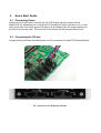
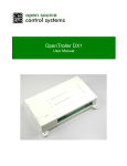
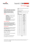
PID Display Module
User Manual
Document Revision 1.0
October 1st, 2011
© 2011 Open Source Control Systems, Inc. All Rights Reserved.
Product warranty or service will not be extended if: (1) the product is repaired, modified or
altered, unless such repair, modification of alteration is authorized in writing by Open Source
Control Systems, Inc. (“OSCSYS”); or (2) the serial number of the product is defaced or
missing.
OSCSYS PROVIDES THIS MANUAL “AS IS” WITHOUT WARRANTY OF ANY KIND AND
MAKES NO OTHER REPRESENTATIONS OR WARRANTIES EITHER EXPRESS OR
IMPLIED AS TO FITNESS FOR PURPOSE, MERCHANTABILITY OR OTHERWISE IN
RESPECT OF THE PRODUCT. IN NO EVENT SHALL OSCSYS, ITS DIRECTORS,
OFFICERS, EMPLOYEES OR AGENTS BE LIABLE FOR ANY DIRECT, INDIRECT,
SPECIAL, INCIDENTAL, OR CONSEQUENTIAL DAMAGES (INCLUDING DAMAGES FOR
LOSS OF PROFITS, LOSS OF BUSINESS, LOSS OF USE OR DATA, INTERRUPTION OF
BUSINESS AND THE LIKE) WHETHER SUCH DAMAGES ARE INCURRED BY THE
PERSON TO WHOM THIS WARRANTY EXTENDS OR A THIRD PARTY, EVEN IF OSCSYS
HAS BEEN ADVISED OF THE POSSIBILITY OF SUCH DAMAGES ARISING FROM ANY
DEFECT OR ERROR IN THIS MANUAL OR PRODUCT.
SPECIFICATIONS AND INFORMATION CONTAINED IN THIS MANUAL ARE FURNISHED
FOR INFORMATIONAL USE ONLY, AND ARE SUBJECT TO CHANGE AT ANY TIME
WITHOUT NOTICE, AND SHOULD NOT BE CONSTRUED AS A COMMITMENT BY
OSCSYS. OSCSYS ASSUMES NO RESPONSIBILITY OR LIABILITY FOR ANY ERRORS
OR INACCURACIES THAT MAY APPEAR IN THIS MANUAL, INCLUDING THE PRODUCTS
AND SOFTWARE DESCRIBED IN IT.
Products and corporate names appearing in this manual may or may not be registered
trademarks or copyrights of their respective companies, and are used only for identification or
explanation and to the owners’ benefit, without intent to infringe.
Contents
1
2
3
4
Overview............................................................................................................................................ 4
1.1
Safety Information...................................................................................................................... 4
1.2
PID Display Module Features .................................................................................................... 4
1.3
Package Contents ....................................................................................................................... 4
1.4
Before You Proceed .................................................................................................................... 4
Quick Start Guide .............................................................................................................................. 5
2.1
Connecting Power ...................................................................................................................... 5
2.2
Connecting the I2C bus .............................................................................................................. 5
2.3
Debug LED Status ...................................................................................................................... 6
2.4
Setting Module Address ............................................................................................................. 6
I2C PID Module Layout .................................................................................................................... 7
3.1
Layout ......................................................................................................................................... 7
3.2
LED Indicators ........................................................................................................................... 8
3.3
Buttons........................................................................................................................................ 8
3.4
Jumpers ....................................................................................................................................... 8
3.5
Connections ................................................................................................................................ 8
Mechanical Specifications ............................................................................................................... 10
4.1
Board Dimensions .................................................................................................................... 10
5
Electrical and Environmental Specifications ................................................................................... 10
6
Appendix A – Warranty ....................................................................................................................11
1
Overview
The PID Display Module was designed to add PID Controller like displays to control systems
like the BrewTroller and the BCS brewing control systems. The display is typically used to
show current and target temperatures for a specific device in large, easy to read digits. The
PID Display Module connects as an I2C or RS-485 slave display device to a control system
and provides no direct monitoring or control of sensors and output devices.
1.1 Safety Information
The PID Display Module is intended to be integrated into a brewing system by the purchaser.
It is solely the purchaser's responsibility to assure that the system is configured in a manner
consistent with applicable safety requirements. Open Source Control Systems, Inc. does not
control how this board is integrated into the purchaser's system and cannot be responsible for
guaranteeing the safety of your system.
The PID Display Module connects to control systems that typically control devices that use
dangerous voltages. Care must be taken that user cannot come in contact with these voltages.
An enclosure that allows for modest ventilation, but prevents intrusion by operator’s hands
and foreign objects should be utilized with this board.
1.2 PID Display Module Features
•
Atmel ATMEGA168 8 Bit Processor with 16kb Flash
•
I2C Communications Interface
•
RS485 Communications Interface (Requires free firmware update; Expected
availability 12/2011)
1.3 Package Contents
•
PID Display Module
1.4 Before You Proceed
Please review all safety and connection information before attempting to connect and power
on your PID Display Module. Open Source Control Systems, Inc. is not responsible for
damage caused to boards by improper connections. If you have any questions please do not
hesitate to contact support. You can find phone numbers and contact forms on our website
(http://www.oscsys.com).
2
Quick Start Guide
2.1 Connecting Power
When using 3 or less units on a chain the I2C PID Display can be powered via the
BrewTroller I2C expansion port. If using the PID Display with other controllers or if you are
using more than 3 units then power will need to be provided via the X2 power connector to
the first device on the chain. Then the rest of the devices will be powered with the bus.
2.2 Connecting the I2C bus
A single locking connector provides power and I2C connectivity to each PID Display Module:
I2C Connection on BrewTroller 4.0
I2C Connection on PID Display Module
I2C Connection on I2CLCD Module
2.3 Debug LED Status
The Debug LED serves as an indicator of board status. When flashing it means the board is
running properly but not receiving any data. A solid Debug LED indicates the board is running
and receiving data. If you have applied power and the debug light does not flash or go solid
then check power connections and try again. If the board still does not respond contact
OSCSYS Technical Support.
2.4 Setting Module Address
If you are using more than one PID Display Module in your system or you want to change the
target address follow the steps below.
1. Press and hold the button labeled SET ADDRESS on the back of the board.
2. The display will show ADDR and will flash the current address of the board for 5
seconds. Release the button if you do not want to change the address.
3. Continue to hold the button and the address will begin to go up, about one per second.
When the address reaches your desired address just release the button. Addresses
are in hexadecimal so keep that in mind when you see addresses like 2a and 3c.
Generally you should use addresses starting at 20 – 2x for however many displays you
have.
4. The display will flash SAVE ADDR for a few seconds and the new address is saved.
The changes take effect immediately.
3
PID Display Module Layout
3.1 Layout
3
4
5
6
7
2
1
1.
2.
3.
4.
5.
6.
7.
8.
I2C Input/Output Connectors
AUX Power Input Connector
Debug LED
Power LED
In Circuit System Programmer (ICSP)
RS485 Termination Enable
RS485 Connector
Address Set Button
8
3.2 LED Indicators
3.2.1
Power
Indicates power is connected to board.
3.2.2
Debug
When this LED is flashing the board is operating normally but not receiving data from the host
controller, if solid means data is being received.
3.3 Buttons
3.3.1
Set Address
This button is used to set the listening address of the device. Press and hold to cycle through
the addresses.
3.4 Jumpers
3.4.1
RS485 Termination
If this device is the last in the RS485 chain then a jumper needs to be installed here.
3.5 Connections
3.5.1
3.5.2
X2 – Aux Power
1.
2.
GND
12VDC
1.
2.
3.
4.
5.
SDA
SCL
N/C
12VDC
GND
I2C Communications Port
3.5.3
3.5.4
ICSP Header
1.
2.
3.
4.
5.
6.
MISO
5VDC
SCK
MOSI
RESET
GND
1.
2.
3.
REF
A
B
RS485 Connector
4
Mechanical Specifications
4.1 Board Dimensions
5
Electrical and Environmental Specifications
Main Power Input
12VDC
Logic-Level Communication 5VDC
Ports
Temperature
0° to +55° C
Relative Humidity
20% to 80% relative humidity, non-condensing
6
Appendix A – Warranty
Open Source Control Systems, Inc. (OSCSYS) warrants that this hardware product is in good
working condition, according to its specifications at the time of shipment, for a period of 90
days from the date it was shipped from OSCSYS. Should the product, in OSCSYS's opinion,
malfunction within the warranty period, OSCSYS will repair or replace the product without
charge. Any replaced parts become the property of OSCSYS. This warranty does not apply to
the software component of a product or to a product which has been damaged due to
accident, misuse, abuse, improper installation, usage not in accordance with product
specifications and instructions, natural or personal disaster or unauthorized alterations,
repairs or modifications.
All warranties for this product, expressed or implied, are limited to 90 days from the date of
purchase and no warranties, expressed or implied, will apply after that period.
All warranties for this product, expressed or implied, shall extend only to the original
purchaser.
The liability of Open Source Control Systems, Inc. in respect of any defective product will be
limited to the repair or replacement of such product. Open Source Control Systems, Inc. may
use new or equivalent to new replacement parts.
Open Source Control Systems, Inc. makes no other representations or warranties as to
fitness for purpose, merchantability or otherwise in respect of the product. No other
representations, warranties or conditions, shall be implied by statute or otherwise.
In no event shall Open Source Control Systems, Inc. be responsible or liable for any damages
arising
(a)
(b)
from the use of the product;
from the loss of use of the product;
(c)
from the loss of revenue or profit resulting from the use of the product; or
(d)
as a result of any event, circumstance, action or abuse beyond the control of Open
Source Control Systems, Inc.
whether such damages be direct, indirect, consequential, special or otherwise and whether
such damages are incurred by the person to whom this warranty extends or a third party.