1
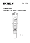
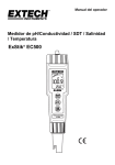
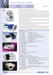
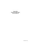
MODEL 430 PORTABLE
pH/CONDUCTIVITY METER
OPERATING MANUAL
430 350/REV A/10-03
MODEL 430 PORTABLE
pH/CONDUCTIVITY METER
OPERATING MANUAL
CONTENTS
Introduction
Specification
Installation
Displays
Controls
Operation
Setting Parameters
pH Calibration
Conductivity Calibration
Error Codes
Manual & Automatic Temperature Compensation
Auto Shut Off
Data Storage
Good Practice Guidelines - pH
Good Practice Guidelines - Conductivity
Maintenance
Troubleshooting Guide
Checking pH Meter Function
Checking Temperature Input
Battery Replacement
Optional Accessories
EC Declaration of Conformity
1
2
3
3-4
5
6
6-7
7
8-9
10
11
11
11
12
13-14
14
15-16
16
17
17
17
18
MODEL 430 PORTABLE
pH/CONDUCTIVITY METER
OPERATING MANUAL
INTRODUCTION
The Model 430 is designed to readily withstand the rigours of
portable analysis, whilst reliably measuring pH and conductivity in
a simple and professional manner. This product allows the
simultaneous readout of pH, conductivity or TDS and temperature
using a custom backlit liquid crystal display. Calibration errors are
clearly indicated, together with the parameter in error.
The 430 offers 1 or 2 point pH calibration and automatic buffer
recognition with a manual override facility. Conductivity calibration
can be performed with direct calibration on standard solutions or
by direct cell constant entry.
The best conductivity/TDS range is automatically selected for
optimum resolution and temperature compensated using an
adjustable temperature coefficient.
The 430 is supplied with a combined pH and conductivity probe
assembly (a temperature sensor is also incorporated to provide
automatic temperature compensation). The probe connects to the
instrument via a single mini-DIN connector for operator
convenience.
An automatic switch off facility helps to conserve battery life, with
low battery indication being shown on the display.
1
SPECIFICATION
pH (1 or 2 point calibration)
Range:
Resolution:
Accuracy:
Conductivity
Ranges:
(automatic selection)
Resolution:
Accuracy:
TDS
Ranges:
(automatic selection)
Resolution:
Accuracy:
Temperature
Ranges:
Resolution:
Accuracy:
ATC range:
Manual Temp. Comp.
Auto pH buffer recog:
Auto conductivity std recog:
Reference temperature:
Cell constant:
EC ratio (TDS)
Temperature coefficient:
Power:
Battery life:
Size:
Weight:
0 to 14pH
0.01pH
±0.02pH
0 to 19.99µS / 0 to 199.9µS
0 to 1999µS / 0 to 19.99mS
0 to 199.9mS
0.01µS, 0.1µS, 1µS, 0.01mS,
0.1mS
±0.5% ±2 digits
0 to 19.99mg/l / 0 to 199.9mg/l
0 to 1999mg/l / 0 to 19.99g/l
0 to 199.9g/l
0.01mg/l, 0.1mg/l, 1mg/l, 0.01g/l,
0.1g/l
±0.5% ±2 digits
-9.9 to +99.9°C
14 to 212°F
0.1°C / 1°F
±0.5°C / ±1°F
0 to 99.9°C / 32 to 212°F
0 to 99.9°C / 32 to 212°F
4.00, 7.00, 9.22 and 10.00
10µS, 84µS, 1413µS and 12.88mS
18, 20 or 25ºC
0.01 to 19.99
0.50 to 0.80
0 to 4.00%/°C
2 AA cells
Typically 100 hours
175(l) x 75 (w) x 35(d) mm
250g
2
INSTALLATION
Unpack the instrument and ensure the following items are present:
1. Model 430 pH/Conductivity Meter (430 201)
2. Combined pH/Conductivity probe (430 231)
3. pH 4, 7 and 10 buffer sachets
4. 2 x AA batteries (021 007) (fitted)
5. Carrying Case (if ordered)
6. Conductivity standards (if ordered)
DISPLAYS
mgL-I
1. Main display - 3½ digit display providing direct readout of
conductivity (in µS or mS) or total dissolved solids (in mg/l or g/l).
The display will also show Underrange (-1) and Overrange (1)
symbols if the instrument is reading outside the operating ranges.
In addition, the display will show an erroneous result momentarily,
at the same time as the secondary display indicates the error
code.
2. Secondary display - 3 digit display showing pH, the cell
constant value (K) or the temperature coefficient as a percentage.
In the event of a calibration error the display will show the error
code momentarily, at the same time as the primary display
indicates the erroneous reading.
3
3. Tertiary display - 3 digit display showing temperature (manual
temperature compensation value or ATC value).
4. CAL 1 or CAL 2 indicator – shows which point of the pH
calibration routine has been reached.
5. Low battery indication – Shown when level reaches approx.
<20%. Sensor calibration and user parameters are retained during
battery replacement.
6. Mode annunciators - the appropriate annunciator is displayed
depending on which mode of operation is selected.
4
CONTROLS
STO RCL
STO stores the current data reading.
RCL recalls the data reading stored.
I:O
Switches the instrument on and off. The
instrument will automatically switch off after 20
minutes if no keys are pressed.
Back light. Pressing this key will illuminate the back
light for 10 seconds. It should be noted that, if
used excessively, this will reduce battery life.
56
Enables adjustment of calibration values and set
up parameters dependent on mode selected.
CAL
Places the instrument into calibration modes.
MODE
Selects conductivity or TDS on the primary display.
Enters conductivity calibration mode after
calibration has been initiated. Allows the user to
gain access to the instrument set up parameters
by holding the key down for 3 seconds.
5
OPERATION
Switch the instrument on by holding down the I:O key for 1-2
seconds. All display segments will be illuminated for approximately
2 seconds. An internal self check routine is run during this display
and on successful completion normal operating mode is activated.
The display will power up showing conductivity, pH and
temperature modes simultaneously.
Remove the electrode from the packaging and ensure it is in good
condition. Connect the electrode to the instrument via the 8 way
mini-DIN socket and remove the wetting cap. Prior to performing
sample measurement it is necessary to perform a 1 or 2 point pH
calibration and/or a conductivity calibration.
The main operating mode displays conductivity, pH and
temperature. Pressing the MODE key toggles the display to TDS,
pH and temperature.
SETTING PARAMETERS
To gain access to the instruments adjustable parameters whilst
measuring, hold down the MODE key for 3 seconds. This allows
the following parameters to be adjusted:
1.Temperature units of measurement – these can be set to °C or °F
using the 56 keys. Pressing the MODE key confirms this setting.
2.Conductivity reference temperature can be adjusted to 18, 20 or
25°C using the 56. Pressing the MODE key confirms this setting.
3. Conductivity temperature coefficient can be set between the
values of 0 to 4.00%/°C. Pressing the MODE key confirms this
setting.
4. EC ratio can be set between the values of 0.50 to 0.80.
Pressing the MODE key confirms this setting. The final MODE key
press will return the instrument to live measurements.
6
pH CALIBRATION
Note: Ensure probes are rinsed between measurements to
avoid solution contamination.
Auto buffer recognition operates over the range of 0 to 100°C,
and will recognise 4.00, 7.00, 9.22 and 10.00 pH buffer values.
Alternative values may be entered manually by using the up/down
keys to set the preferred values. However, this then disables the
auto buffer recognition feature. To retrieve the auto buffer
recognition values it is necessary to exit the calibration sequence
by pressing the mODE key.
Place the combined sensor assembly into the first buffer
solution.
Pressing the CAL key places the instrument in the pH calibration
mode and flashes the Cal 1 icon. The current pH reading is
displayed on the secondary display with probe potential (mV) now
being displayed on the primary display. If manual temperature
compensation is selected the °C symbol will be flashing.
A subsequent CAL key press calibrates to the nearest standard
buffer. Alternatively, the up/down arrow keys can be used to set
the secondary pH display to the required value after the first
press of the CAL key. Pressing the CAL key again confirms the
set value. The Cal 1 icon is extinguished and the Cal 2 icon will
flash. (If a 1 point calibration only is required, exiting the calibration
sequence can be performed by pressing the MODE key. The
instrument will return to live conductivity and pH readings.)
Place the combined sensor assembly into the second buffer
solution.
To perform a two point calibration a subsequent CAL key press
calibrates to the nearest standard buffer or the up/down arrow
keys can be used to set the secondary pH display to the required
value. Pressing the CAL key again confirms the set value. The
instrument will then return to live conductivity and pH readings.
7
CONDUCTIVITY CALIBRATION
a) WITH KNOWN CELL CONSTANT
Auto standard recognition operates over the range of 0 to 100°C,
and will recognise 10µS, 84µS, 1413µS and 12.88mS.
Alternatively, the up/down arrow keys can be used to manually
adjust the cell constant (K) and subsequent conductivity reading
to the required value, confirmed by pressing the CAL key.
When measuring, pressing the CAL key places the instrument in
the pH calibration mode and flashes the Cal 1 icon. Pressing the
MODE key skips further action, places the instrument in
conductivity calibration mode and flashes the conductivity Cal
icon. Current conductivity readings are displayed in the primary
display with cell constant (K) being displayed in the secondary
display.
The 56 keys can then be used to adjust the cell constant to the
value indicated on the conductivity cell being used.
The use of the cell constant as a calibration method is only
recommended where no standard exists. This calibration method
will not account for changes in the probe characteristics over time
or any other factor which may affect the reading. The use of a
known calibration standard is always recommended.
b) ON STANDARD SOLUTION (Auto Value Recognition)
When measuring, pressing the CAL key places the instrument in
the pH calibration mode and flashes the Cal 1 icon. Pressing the
MODE key skips further action, places the instrument in
conductivity calibration mode and flashes the conductivity Cal
icon. Current conductivity readings are displayed in the primary
display with cell constant (K) being displayed in the secondary
display.
8
Place the combined sensor into the calibration standard. Press the
CAL key and allow the reading to stabilise.
A subsequent CAL key press calibrates to the nearest
conductivity standard and returns the instrument to live
conductivity and pH readings.
To abort the calibration sequence at any time press the MODE key.
c) ON NON-STANDARD SOLUTION (Manual Value Entry)
When measuring, pressing the CAL key places the instrument in
the pH calibration mode and flashes the Cal 1 icon. Pressing the
MODE key skips further action, places the instrument in
conductivity calibration mode and flashes the conductivity Cal
icon. Current conductivity readings are displayed in the primary
display with cell constant (K) being displayed in the secondary
display.
Place the combined sensor into the calibration standard. Enter the
preferred calibration standard value using the 56 keys (this
also adjusts the cell constant value). Allow the reading to stabilise.
Press the CAL key again to complete the calibration.
To abort the calibration sequence at any time press the MODE key.
9
ERROR CODES
Any errors encountered during either a pH or conductivity
calibration are indicated for three seconds by an error code
displayed on the secondary display and the parameter in error
displayed on the primary display. If a problem is detected the
following error codes will be displayed:
Err1
Err 2
Err 3
Err 4
This indicates that the calculated electrode offset at 7pH
is outside the range of -30mV to +30mV. The error code
will be displayed for 3 seconds on the secondary
display, together with the erroneous electrode offset
value in mV on the primary display. The instrument will
then reset the calibration data back to the ideal Nernst
response of 0mV offset at 7 pH and a slope of
59.16mV/pH at 25°C.
This indicates that the slope value is out of range. The
error code will be displayed for 3 seconds on the
secondary display, together with the erroneous value as
a % on the primary display. The instrument will then
reset the calibration data back to the ideal Nernst
response of 0mV offset at 7 pH and a slope of
59.16mV/pH at 25°C. The allowable range for slope is
75% to 125% of the ideal Nernst figure.
This indicates that the instrument has not recognised the
buffer. The displayed reading must be within 1pH unit of
the calibration buffer value for automatic buffer
recognition. The error code will be displayed for 3
seconds on the secondary display, together with the
erroneous pH buffer value on the primary display. The
instrument will then reset the calibration data back to the
ideal Nernst response of 0mV offset at 7 pH and a slope
of 59.16mV/pH at 25°C.
This indicates that the calculated conductivity cell
constant (K) is out of range (0.01 to 19.99).
10
MANUAL & AUTOMATIC TEMPERATURE COMPENSATION
When making measurements without ATC the units of
measurement will flash on the display. The displayed temperature
reading can be adjusted to the correct value using the56 keys.
AUTO SHUT OFF
This will occur after 20 minutes if no key is pressed
DATA STORAGE
The 430 holds 1 reading in its internal memory.
Press the STO key to store the current reading. Sto will
momentarily be displayed, then the instrument will return to the
previous operating mode.
Press the RCL key to recall the stored reading. rCl will
momentarily be displayed, then the instrument will display the
previously stored reading. The HOLD symbol will also be
displayed.
Press the MODE key to return to normal operation.
It should be noted that it is not possible to delete the stored
reading. The reading will be overwritten when the next reading is
stored.
11
GOOD PRACTICE GUIDELINES – pH
The types of pH electrodes are many and various. The supplied
epoxy combination electrode is suitable for the majority of tests
carried out on aqueous solutions.
The following general guidelines indicate the care and
maintenance required:
1.
2.
After use – rinse thoroughly with distilled water.
Short term storage – immerse in storage solution (025 192)
Long term storage – fit wetting cap filled with storage
solution (025 192) and replace in original packaging
Electrodes should be stored:
a) away from direct sunlight
b) in a vertical position
c) within their specified temperature range
3. Always ensure the electrode is used within its specified
temperature range. Ageing of electrodes used above their
specified temperature is rapid and irreversible.
4. DO NOT touch the sensitive glass pH membrane during use.
Excess droplets of solution may be removed by gently blotting
with filter paper or tissue. DO NOT rub the electrode as this may
induce an electrostatic charge.
5. During use ensure the electrode is rinsed between each
measurement to eliminate the contamination of solutions.
12
GOOD PRACTICE GUIDELINES - CONDUCTIVITY
1.
2.
3.
4.
5.
6.
7.
The presence of particulate matter in the sample can lead
to unstable and non-reproducible results. If necessary
filter, or allow the particles to settle prior to immersion.
Ensure no air bubbles are trapped in the measuring cell.
Gentle agitation of the cell should ensure that bubbles are
purged.
The entire plate area must be immersed in the solution
under test. The slots in the side of the sensor should be
below the surface.
When measuring samples at a temperature that differs
significantly from ambient, sufficient time must be
allowed for the internal temperature sensor to respond
to this change.
Measuring low conductivity samples must be performed
with great care to avoid contamination. At the lowest
levels readings may be affected by the leeching of
substances from the sample container or absorption of
gases from the atmosphere.
It is advisable to clean the sensor if contamination is
evident. This should be approached in a progressive
manner, beginning with deionised water and
progressing to other solvents or a soft air brush if the
deposits persist. The carbon plates can be damaged
and should not come into contact with anything which is
likely to abrade their surface.
The temperature coefficient is very dependent on the
solution being measured and its concentration level. The
effect of temperature change on conductivity can be
very significant, and if the temperature coefficient is not
known it is wise to measure all samples at the same
temperature.
13
8.
The TDS mode displays results which have been
calculated from the measurement of conductivity and
assumes some knowledge of the electrolyte balance of
the analyte. The EC ratio allows selection of a factor
suitable for the solution under test. Most analysers which
do not offer this option use a default value of 0.6.
MAINTENANCE
CLEANING/RE-CONDITIONING OF GLASS ELECTRODES
For general purpose use, combination electrodes can be cleaned
with a mild detergent solution or a commercial glass cleaning
solution (provided these are not strongly acidic). The electrode
surface should be wiped with a clean cloth soaked in the cleaning
agent, and/or allow the membrane to stand in the solution until
clean. Rinse and repeat as necessary.
TABLE FOR CLEANING OF GLASS ELECTRODES
NOTE: The epoxy bodied electrode supplied with the
instrument should not be cleaned with aggressive
solvents.
Deposit
Cleaning agents
General deposits
Mild detergent solution
Inorganic coatings
Commercial glass cleaning solution
(not strongly acidic)
Metal compounds
Acid solution, not stronger than 1M
Oil/Grease
Complexing agent (EDTA) or suitable
solvent
Resins/Lignins
Acetone, alcohol or detergent (not strongly
alkaline)
Proteins (blood, etc) Enzyme solutions e.g. Pepsin in 0.1M HCl
Stubborn deposits
Weak hydrogen peroxide solution, Sodium
Hypochlorite solution or domestic bleach.
Electrodes which have been allowed to dry out, (often indicated
by a hard, dry deposit of KCl crystals on the electrode body),
should be rehabilitated by soaking overnight in warm distilled
water.
14
TROUBLESHOOTING GUIDE
FAULT
PROBABLE CAUSE
ACTION
No power
Battery failure
Battery polarity incorrect
Replace batteries
Refit batteries
Cal error
1, 2 or 3
Incorrect value pH buffer usedUse correct value
Contaminated buffer solution Use fresh buffer
solutions
Cal error
1 or 2
Replace pH electrode
pH electrode defective
Same buffer used for 2 point Recalibrate on 2
cal
buffer solutions
Unstable
display
pH electrode defective
Replace pH electrode
Display
shows 1 or
-1 only
Intermittant / no connection
pH electrode defective
Contaminated solutions
Check electrode
connection to unit
Replace pH electrode
Replace solutions
Intermittant
display
Probes not fitted correctly
Check connections
I/O key not held down >2
I/O switch
not working secs
56 keys
Operating in incorrect mode
Refer to operation
section of manual
Incorrect standard used
Incorrect manual standard
value entered
Faulty or incorrect
conductivity probe fitted
Use correct standard
Enter correct value
not working
Cal Error 4
Retry holding key for
2 seconds
15
Replace probe
TROUBLESHOOTING GUIDE
FAULT
PROBABLE CAUSE
ACTION
Unstable display
Conductivity cell
defective
Replace conductivity
cell
Back light not on/
goes out
10 second time
elapsed/normal
function
Recheck
Reading drifts
Conductivity cell stored
dry
CO2 absorbtion by
sample
Allow to soak for 2
hours
Noticeable for low
conductivity - do not
allow sample to stand
in unstoppered bottles
Non linear
readings
Conductivity cell not
zeroed
Zero conductivity cell
Poor
reproducibility
Carryover between
solutions
Rinse cell in distilled
water between
measurements
If a fault is identified during the start up self check routine an error
code will be displayed. This indicates an internal hardware or
software software problem. In the event of this, please contact
your local distributor or service agent.
CHECKING pH METER FUNCTION
Connect the meter to a mV source and apply 0mV. Press the Cal key
and the display should read 7 pH.
Apply +180mV and calibrate to 4 pH.
Apply -180mV and the display should show 10 pH.
Re-calibrate using a known good electrode.
16
CHECKING TEMPERATURE INPUT
Apply a 10.0Kohm resistor across the pins shown:
Check the display reads 25.0°C ±0.5°C
BATTERY REPLACEMENT
It is strongly recommended that the batteries be replaced
immediately the low battery indication is given to avoid compromising instrument readings. To fit new batteries; loosen the battery
compartment cover (the screws are captive in the cover), remove
and carefully discard the used batteries. Fit the new batteries,
type R6, AA or AM3, ensuring the correct polarities are observed,
as indicated on the moulding. Refit the battery compartment cover,
ensuring that the fixings are secured into place, but are not
overtightened.
OPTIONAL ACCESSORIES
The following list of items are available for use with the Model 430:
033 269
025 139
025 164
025 138
025 156
025 179
025 180
025 181
Carrying Case
Conductivity Standard 10µS
Conductivity Standard 84µS
Conductivity Standard 1413µS
Conductivity Standard 12.88mS
pH 4 buffer sachets (pack 10)
pH 7 buffer sachets (pack 10)
pH 10 buffer sachets (pack 10)
17
EC Declaration of Conformity
JENWAY Model 430 pH/Conductivity Meter complies with the
following European Standards:
EN 50081-1:1992 Electromagnetic compatibility - Generic emission
standard
EN 61326:1998 Electrical equipment for measurement, control and
laboratory use - EMC requirements
EN 61010-1:1993 Safety requirements for electrical equipment for
measurement, control and laboratory use
Following the provision of:
EMC Directive - 89/336/EEC and Low Voltage Directive - 73/23/EEC
Carl Warren
Technical Manager, Jenway,
Gransmore Green, Felsted, Dunmow,
Essex, CM6 3LB, England
18