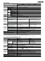
1
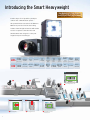
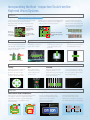
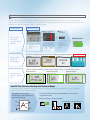
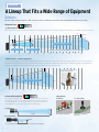
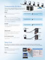
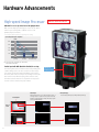
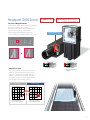
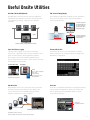
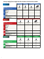
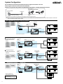
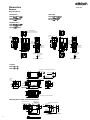
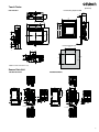
Introducing the Smart Heavyweight
New Models with Code Reading
and OCR with Built-in Dictionary
Flexible inspection capabilities, multiple
camera and communication options -this powerful vision sensor has it all. Omron’s
FQ2 Series provides all of the best-selling
features found in high-end models without the
need for a separate controller. This new
Smart Camera was designed to solve your
toughest inspection challenges.
Code Highspeed
Reader image
processor
OCR HDR
Megapixel
capacity
Real
color
Sub-pixel High-power
processing
lighting
Monochrome
C
-mount
9
inspection
items
11
image
filters
32 360°
-camera
expansion
I/O
IP67 E-IP PLC
FINS 34points
Link
position
compensation
RS232C
Ultrawide
field of view
Password
DAP
partial input
Image
inversion
OK
1
2
4
4 Reading Barcode
5
NG
1 Missing Pill
2
NG
2 Misalignment
OK
3
3 Package Insert
Detection
Three Advantages for Effective Machine Design
All in One Vision Sensor
All-in-one compact size that is perfect for use in
Compact
tight spaces or as an aftermarket option. Compared
Body
to more-advanced Vision Sensors with multiple
components, this Sensor boasts a much more
efficient hardware design.
Image Sensor, OCR, and
Code Reader in One
Extended
The OCR function adds to the sensing solution
and provides a powerful upgrade. It features
a "built-in" dictionary ability to recognize
15 Code types.
Functions
Date
Verification
Bar Code
2D Code
Label out of
place
A Lineup That Fits a
Wide Range of Applications
Diverse
Expanded inspection menu, camera variations,
and communication interfaces. With a wide range
Lineup
of sensors, an option for every application now
becomes a standard option.
OK
OK
OK
5 Hot-melt Detection
6 Date Verification and
7 Reading Barcode
de
6
Tape Detection
7
3
Compact
All You Need is One
Combined Lighting, Controller and Communications
Image Processor
Although previous Vision Sensors placed the image
processor in a separate Controller, now we have built
the processor into the camera unit.
High-power Lighting
Built-in high-power lighting capable of evenly
lighting across a wide field of view. Providing
sufficient lighting even when the polarizing filter
is used.
Adjustable Lens
The focus of the lens
can be adjusted for
the specific field of
view and installation
distance you need.
Focus adjustment screw
I/O Power Supply Connector
The external output line for inspection results, the
input line for changing the setup, and the power
supply line are all combined into one connector.
Ethernet Connector
Commands can be input from a PLC to control
the FQ2, and inspection results and measurement
results can be output from the FQ2 to a PLC. You
can also transfer images to a computer.
IP67 Water Resistance
Flexible Cables
Smart Click Connectors
1
The sensor can be used in wet
environments.
4
All cables from the camera are flexible.
This allows the sensor to be used safely
on moving parts.
2
Connection is made quick and easy with a
clear, definitive click-into-place
mechanism.
Quick and Easy Design and Installation
Easy Product Selection
All you need to do is select the camera based on the field of view and installation distance that you require. There is no need to
select and purchase additional lighting or lenses. Furthermore, the time required to wire everything has been drastically reduced
due to the low number of components.
Other Vision Systems
7
or
more
components
FQ2-series Smart Cameras
Only
2
Controller
components
Camera
Console
Monitor
Lens
Sensor
Lighting
Power supply of lighting
Monitoring and Setup Tool
Touch Finder or PC Tool
Easy Installation
The camera and lighting have been integrated into a single unit, so only one camera mounting bracket is required. The sensor
comes with a multi-directional mounting bracket that can be attached on any of the four sides of the camera. Axis alignment is
not required because the lighting and the camera are integrated into a single unit.
Other Vision Cameras
The optical axis must be adjusted
because of two components
are mounted.
FQ2-series Smart Cameras
1
Only
Multi-directional Mounting Bracket
1
mounting
bracket
1 Mount camera.
2
2 Mount lighting.
3 Align the optical axes.
Easy Expansion
3
Up to 32 Cameras
Simply install the cameras where you need them, when you need them. No control panels are required to house the controllers.
Triggers can be input for each camera, so new cameras can be added whenever required without having to worry about timing
input design. Up to 32 cameras can be set up from a single Touch Finder without adding new monitors when you need
more cameras.
Other Vision Systems
A separate controller is
needed to add a
new camera.
FQ2-series Smart Cameras
Add or remove up to 32 Cameras
all set-up from one Touch Finder.
Up to
32
cameras
Triggers
5
Extended Functions : Image Inspections
Easily Perform Both Inspection and Positioning
You can combine multiple inspection items to perform external inspections, positioning, and other tasks all from a single Sensor.
External Inspection
External inspection of ICs can be completed with a single Sensor.
The position offset of the entire pallet before inspection can be adjusted on
the image itself, which reduces the amount of work required to increase
mechanical positioning accuracy.
Pitch
inspections
Number of pins
Width
measurements
Measurement Flow
Purpose
Image Filters
Adjusts the image so that
it is easier to inspect
Position compensation
Compensates for the position
offset of the chip.
Inspections
Edge Count
Incomplete
characters
Foreign matter
Chip position
offset
Sensitive Search
Color Data
Edge Position
Number of pins and pitch
inspections
Incomplete characters
Foreign matter
Width measurements
Calculations and Outputs
Calculation
Data Output
Individual Judgement Output
Uses the inspection data for
calculations and judgements.
Outputs the measurement
values.
Outputs the judgements of
inspections to individually.
Component Positioning
The Sensor can measure angles of rotation and other position information,
so it can also be used for positioning. Inspections can also be performed for
the number and size of holes along with the position information.
Measurement Flow
Image Filters
Purpose
Number and Sizes of Holes
Adjusts the image so that
it is easier to inspect
Inspections and Measurements
Shape Search II
Labeling
Component incline and position
Number of holes and hole sizes
Angle
Calculations and Outputs
Calculation
Data Output
6
Calculates data for external output.
Outputs the position information and incline.
Incorporating the Best - Inspection Tools from the
High-end Vision Systems
Search Tools
Shape Search II
Multiple searches can be performed simultaneously,
which enables the inspection of the number of
items in a pallet or picking applications.
Workpieces are
detectable even
if they are rotated
up to 360°
0
2
Workpieces
are detectable
even if there
is overlapping.
4
4
5
Sensitive Search
Ten Times Faster Than Previous Searching
General searches have a difficult time with overlap
or 360° rotation, but this Sensor achieves
high-speed, stable searching of any shapes that
match the model.
1
Search Tools
Deformed, faulty
products are judged
as NG.
7
3
5
0
6
8
1
Through automatic division and
matching of the model image, tiny
differences that cannot be detected
with a normal search can be detected
with large numerical differences.
OK
Workpieces are detectable
even with different amounts
of light.
One character is missing.
NG
Edge Tools
Search
Edge Pitch
Edge Position
Edge Width
This is a standard search inspection
item. This type of search is used to
detect items like labels, identify
shapes, or positions.
The number of edges in a
region can be counted.
This inspection item detects
edges and measures their
positions.
This inspection item measures
the width between edges.
Detection of Promotional Stickers
Area and Color Tools
Labeling
Area
Color Data
This inspection item counts how
many labels there are of the
specified color and size and
measures the area or center
position of the specified label.
This inspection item
measures the area and
center position of the
specified color.
Inspections can be performed that
compare the difference in color
between the workpiece and a registered
image of a good product to detect
objects and foreign matter.
You can also inspect for defects
and foreign matter by looking at
the color deviation. (Referenced
from original sample.)
Utility Items
360° Rotational Position Compensation
Image Filters
Calibration
Inspections for products with inconsistent position
can easily be corrected. Compensation of the
placement of inspection regions simplifies the
manufacturing process with the ease of
product tracking.
A total of 11 different image filters
are provided, including background
suppression to help eliminate
patterns that can result in
unstable measurements.
Pixel unit measurement can be
converted to user units for the
dimensions of a workpiece, providing a
user display that is easy to understand.
With Background
Suppression
Without Background
Suppression
150 pixels
8 mm
7
Extended Functions : Optical Character Recognition (OCR)
New OCR Method without Character
Registration into a Dictionary
Date Verification
Even if printing is distorted or unclear due to
conveyor line conditions, a unique reading method
with a built-in dictionary enables stable reading
of characters.
Measurement Flow
Purpose
Reading Characters
OCR
Reading characters
Verification against
reference data
Outputs
Judgement Output
Outputs the judgement
result from verification
at .
Worn Characters
Distorted Characters
Character Verification and Label Position Inspection
Although previously performed as separate processes, character verification and inspections can now
both be performed with one FQ2 Sensor. This helps
you reduce costs and save space.
Measurement Flow
Image Filters
Position Compensation
Other Vision Sensors
What was two processes...
Purpose
Adjusts the image so that it is
easier to inspect.
Character or code reading with an imager
Label inspection with a Vision Sensor
Compensates for the
position of the box.
FQ2-S4/CH Series Smart Camera
Inspections
OCR
Reads the lot number and date.
Search
Label position inspection
Character Verification
Calculations and Outputs
Individual Judgement Output
...is now combined into one process.
OK
NG
Outputs the judgements of
and .
Label Position Inspection
8
OCR with Built-in Dictionary
OCR
The built-in dictionary contains approximately 80 different fonts that are used on the factory floor. Variations for worn characters, blurred,
distorted, different backgrounds, and size changes have been included to enable stable and highly accurate readings. It is not necessary to set
parameters to compensate for character contrast or positional offsetting.
Conventional OCR
Built-in Dictionary
Draw boxes around characters.
Set the character formats.
Press the
TEACH Button.
Top: Character string read
Time is required
for character
registration into the
dictionary.
Reading is started.
Bottom: Character format
Up to four lines can be read.
The following characters can be read.
Letters of the
alphabet: A to Z (uppercase)
Numbers: 0 to 9
Symbols: ‘ - . : /
The character extraction
conditions are
automatically adjusted
according to the
conditions of the printed
characters.
The character format is displayed
from the read results. Set the
character format according the
format of the characters to read.
Letter: $
Number: #
Symbol: @
Not read: *
Number or letter: ?
Characters from most printers can be read, including dot and impact printers.
Different printers
use different
printing methods.
Hot Printer
Inkjet Printer
Thermal Printer
Handles Approx. 80 Fonts
Laser Marker
Unique recognition technology enables stable readings of worn out or distorted characters.
Worn and inclined
characters cannot be
read.
Worn Characters
Inclined Characters
Small Characters
New OCR Tool: Character Matching with Structural Models
In some applications it is required for image matching methods, but thanks to the structural model matching of specific characteristic
points there is no need for character registration.
Structural models record the
characteristics of each character in
approximately 80 fonts.
A
A
The position and the structure of characteristic points are used to
recognize characters.
Background Changes
A A
Size and Font Changes
Worn Characters Inclined Characters
A
9
Expanded Functions : Code Reader
Capability to Read Any of 15 Code Types from
Paper Labels to Direct Marking
Code and Character Verification
OCR and Code Reading inspection items can be combined to read
codes and verify them against character strings all within the FQ2.
No programming of external devices is required.
Measurement Flow
Position Compensation
Purpose
Compensates for the
position of the box.
Reading
Bar code
Reads the barcode.
OCR
Reads the character string
and verifies it against the
barcode in .
Outputs
Outputs the verified
character string.
Data
Reading Direct Marking Codes
It is common to manage information by using direct marking codes on
products. However, differences in materials often causes instability
when reading the printed characters. The FQ2 achieves stable reading
with unique functionality designed just for DPM (Dot Peen Marking).
Measurement Flow
Purpose
Marking on Resin
Code Reading
Reads 2D code.
2D-code (DPM)
Outputs
Data Output
Data Matrix
Marking on Small Parts
10
Marking on Film or Glass
Marking on Metal
Data Matrix
Outputs the information
that was read.
Data Matrix
Data Matrix
Paper Labels
Barcodes
2D Codes
The FQ2 can read the main nine types of barcodes. Additionally,
the FQ2 can be used in pharmaceutical applications, where
verification of barcodes and characters is required.
The FQ2 can read the main six types of 2D codes. You do not need
to use more than one code reader even for processing that
combines different types of codes.
JAN/EAN/UPC
Code39
Codabar (NW-7)
Data Matrix
QR Code
Micro QR Code
ITF (Interleaved 2 of 5)
Code93
Code128 / GS1-128
PDF417
Micro PDF417
GS1-DataMatrix
GS1-DataBar
GS1-128 Composite Code
Pharmacode
Direct Marking
2D DPM (Dot Peen Marking) Codes
When 2D codes are printed on metal, substrates, glass, or other
materials, the printed 2D codes can be inconsistent. Even with
these difficult-to-read codes, the FQ2 is equipped with filters and
retry processing designed just for DPM to allow you to easily and
stably read the codes.
Data Matrix(EC200)
QR Code
Types of Filtering
In order to achieve stable readings you can remove printing
irregularities and noise by applying up to three of the four
unique filters developed by OMRON.
Smooth
Combining Filtering
Erosion and dilation can be combined to connect dots without
changing the dot thickness.
Smooths the image.
Dilate
For white codes, increases the cell size.
Effective for reading codes with cell spreading.
Dilate
Erosion
For white codes, reduces the cell size.
Effective for reading separated dot codes.
Median
Removes noise.
Erosion
Retry function
Code readers must overcome environmental and poor printing conditions that cause unstable readings. The FQ2 has a retry function that
retries readings by changing the exposure time and other reading conditions.
1
Retrying the Specified Number of Times
with the Same Conditions
3
Reading is performed for the specified number of times
for the same scene.
NG
2
NG
Reading is performed until successful, as long as
an external level trigger is input.
During level trigger input
NG
NG
Reading is performed for the same scene while changing the exposure time in stages.
OK
Retrying While External Trigger Is Input
OK
Retrying While Changing the Shutter Speed
4
NG
NG
NG
OK
1ms
1.3ms
0.7ms
1.6ms
Retrying While Changing the Reading Conditions
When reading DPM codes, inconsistencies in
printing conditions can result in NGs if
reading is performed with only one set of
reading settings. The FQ2 allows you to
register up to 32 sets of reading conditions
as scenes and retry reading while changing
the scenes in order. The system automatically determines the scenes with the highest
usage rates and changes the order to start
with them to flexibly handle changes in
reading conditions. Of course you can
specify a fixed order if required.
NG
NG
OK
Scene 1
Scene 2
Scene 3
Register 32 sets of reading conditions.
Rapidly switch to the optimum reading conditions.
Scene 2
Scene 1
Scene 4
Scene 3
Scene 6
Scene 5
Scene 8
Scene 7
Scene 32
Scene 31
11
Versatile
A Lineup That Fits a Wide Range of Equipment
Sensors
We offer a diverse lineup of Sensors so that you can choose the one with the perfect field of view and installation distance for your needs.
Integrated Sensor
Color
Monochrome
Seamless Field of View Variations
All-in-one Sensors tend to be limited in field of view variations, but we offer a lineup ranging from 7.5 mm up to 240 mm to meet your needs.
970
7.5
6.7
53
13
11.6
Wide View (Long-distance) Sensor
47.3
Narrow View Sensor
0
240
220
215
56
38
Unit: mm
Standard View Sensor
100
200
214
This illustration shows the field of view and installation distance of a 760,000-pixel Sensor.
300
400
500
600
700
800
900
1000
Wide View Sensors -- Perfect for Tight Spaces
A side-view wide-angle camera takes images and performs inspections across a wide area, even if the camera is close to the workpiece.
Perfect for mounting the sensor in locations with limited space. This also enables the Sensor to be installed alongside an assembly line
without protruding in order to perform inspections from the side of the conveyor belt.
380
Inspection for Presence of Markings Inside a
Vertical Form-fill-sealing Machine
300
32
29
25.9
0
Wide View (Short-distance) Sensor
100
200
Sensors with C-mount lens
300
Color
400
268
500
600
Monochrome
700
800
900
1000
Lighting Examples
The Sensors with C-mount lens enable freedom of lens selection for
long distances over 1 m and narrow fields of view under 1 mm that
are not covered by our integrated Sensors. This type of Sensor is
also useful when you want to use external illumination.
Backlighting
Low-angle Lighting
External Shape Inspections
Defect and Foreign Matter
Inspections
Long Distance
1m
10 m max.
Narrow Field of View
1 mm min.
65mm
Note: A commercially available telecentric lens is required for narrow field of view applications.
12
Communication Interfaces
The Sensor includes communication interfaces to connect with a wide range
of host devices. Saving setup time for communications between the sensor
and the PLC.
PLC Link
PLC link greatly reduces the amount of time and work
required to create ladder programs.
Note: The type of communications interface depends on the model of the Sensor.
Refer to page 22 for details.
Compatible Models
OMRON PLCs: CS, CJ1, CJ2, CP1 and NSJ Series
Mitsubishi Electric: Q Series
Compatible Models
OMRON PLCs: CS, CJ1, CJ2, CP1 and NSJ Series
Compatible Models
OMRON Machine Programmable Controllers: NJ Series
OMRON PLCs: CS, CJ1 and CJ2 Series
FINS
OMRON’s exclusive FINS/TCP communications
interface can be used to connect to low-cost OMRON
PLCs. With this communications interface, no communications controls are required to process the sending
and receiving of complex TCP packets. You get faster,
simpler connections to OMRON PLCs.
EtherNet/IP
EtherNet/IP communications enable simple and easy
connections to a wide range of EtherNet/IP devices,
including OMRON PLCs.
Inputs: 11
Outputs: 24
Inputs: 7
Outputs: 3
I/O Expansion Units
Our expansion units enable expansion of up to three
times the number of I/O points. This enables the
output of individual judgement results for each
inspection.
FQ-SDU1FQ I/O
Sensor Data Unit
FQ-WU Sensor Data Unit Cable
Inputs:8
Outputs:7
RS-232C Communications Unit
RS-232C
This Sensor Data Unit supports standard RS-232C
communications.
FQ-SDU2 RS-232C
Sensor Data Unit
FQ-WU Sensor Data Unit Cable
Setup Tools
We provide two tools for configuration and monitoring of inspection images: the Touch Finder, which can be used onsite to change
settings and which can be installed on a control panel, and the Touch Finder for PC software which is Windows XP/7 (32/64 bit compatible).
Touch Finder
This is a small monitor with a touch panel. It's durable,
rugged design is shock-resistant and portable. It has
passed our standard 1.3 m drop test.
PC Tool
Emulates TouchFinder functionality on a PC.
On-screen Messages in Nine Languages
English
German
Traditional Chinese
French
Simplified Chinese
Italian
Korean
Spanish
Japanese
13
Hardware Advancements
High-speed Image Processor
3X Faster than Previous Models
600 mHz Processor provides faster throughput times!
With our new high-speed image processor we are able to
achieve a processing time of 50 ms or less for all
primary inspection items.
* Processing may take longer than 50 ms depending on the settings.
Search Inspection Speed Comparison
110 ms
100ms
80ms
1/3
60ms
1/5
40ms
30 ms
20ms
FQ-S
Color Image
FQ2-S
Color Image
22 ms
FQ2-S
Monochrome Image
Note: This comparison was conducted with a 752 × 480 pixel image,
with no rotational compensation.
Partial Input with DAP (Dual Axis Partial) Processing
Processing time can be further reduced by limiting the
camera image size to an area focused for the inspection. Previous models allowed trimming only in the Y
direction, but now you can specify a range across both
the X and Y axes while keeping a wide field of view,
trim the sections that are not required for inspection
in each scene to reduce inspection time.
Partial Input Y
Workpiece A
Field of
View Y
Partial
Input X
Field of View X
Workpiece B
14
High-speed
Image Processor
Partial Input
Enlarged Display
Partial input allows you to input only the portion of
an image that is required for inspection without
having to change the field of view, and each program
can be set independently.
You can enlarge the display of the partial input image.
Megapixel CMOS Sensor
4 Times the Pixels
1,000 Times the Display Resolution
(Comparisons to previous OMRON models)
Precision 1.3 Megapixel Camera
Would you like a little more positioning accuracy?
Do you need a wider field of view?
We hear you, and that is why we have greatly
improved the resolution of our camera.
The 1.3 megapixels maintain precision and
accuracy while also enabling a wider field of view.
Megapixel CMOS Sensor
1.3 megapixels
350,000 pixels
1.3 Megapixels
Color
Monochrome
Sensor with C-mount
Sub-pixel Processing
Color
*
Monochrome
Integrated Sensor
*.350,000 pixels types are also
available.
Previously, position information could only be
output on a per-pixel basis, but now you can
output at a resolution even higher than the
number of available pixels. This provides finer
measurement values for travel distances and
helps to improve positioning accuracy.
Typical Problem
760,000 Pixels
Sub-pixel Processing
1,000x
improvement
1-pixel
increments
The position of the edge
cannot be detected accurately.
0.001-pixel
increments
The position of the edge is
detected with greater accuracy.
15
Three Key Technologies for Crystal Clear Images
Real-color Sensing
Real-color processing is an image processing technology that performs high-speed processing of full-color images with a total of 16.7
million colors (256 tones per RGB channel). This means that image processing can be performed with the same color information
that is visible to the human eye, and stable measurements can be performed under lighting that closely resembles natural light.
Real color image processing
Color Image Processing
Color variations between 16.7 million
different colors can
be captured without
any color loss.
Dark
Bright
Binary image processing
Dark
Black
White
Black
The camera image is processed as-is without any
Captured images are converted to a 256-shade
Captured images are converted to a black and
loss of quality.
monochrome image and processed. This enables
white two-color image and processed. This reduc-
This enables even the slightest of color
more stable inspection compared to binary level
es the amount of data and enables high-speed
differences to be captured with high accuracy.
processing, but slight changes in color cannot be
processing.
detected with this method.
Previous Image Processing
OMRON FQ2 Series
HDR Sensing
High dynamic range minimizes the effects of lighting such as halation and allows highly precise inspections.
Conventional images
HDR image
Halation
Dynamic range
of the upper image
Dynamic range
after HDR
processing
Underexposure
Industry's highest
dynamic range
Max. 5000 times
higher than
previous models
Dynamic range
of the lower image
Defects Undetectable Due to Overexposure or Underexposure
Any spot outside the dynamic range is blurred by halation or shadow.
Defects Detectable Even on Reflective or Shadowy Surfaces
The surface of the workpiece is accurately reproduced and detected even with overexposure or
underexposure.
Polarizing Filter + High-power Lighting
Lighting is required for stable image inspection, but shiny surfaces can reflect light, resulting in incorrect judgements. You
can use a polarizing filter to reduce specular reflection, but the entire image will be darker, which can result in insufficient
image contrast.
The FQ2 Series is equipped with OMRON’s own high-power lighting DR optical system for effective use of LED power. This
system provides sufficient lighting for inspection even when the enclosed polarizing filter is used.
Standard Lighting
Light is reflected.
16
Standard Lighting + Polarizing Filter
The overall image is dark;
inspection becomes unstable.
High-power Lighting + Polarizing Filter
Overall image contrast is maintained,
and only reflections are eliminated.
Useful Onsite Utilities
Real-time Threshold Adjustment
180° Inverted Image Display
The FQ2 smart camera allows fast and easy judgement
adjustment. This eliminates the need to stop the machine
for fine tuning of settings, resulting in zero machine
downtime.
Invert images by 180° when an image can only be taken in
the incorrect orientation due to the position that the
Sensor was mounted in.
The image is displayed in
the direction opposite of
the actual travel direction, which makes the position difficult to adjust.
Continuous inspection
180° inversion
Updated
The image is displayed in
the same direction as it is
actually traveling.
Judgement conditions can be adjusted on the Touch Finder.
Inspection History Logging
Password Protection
“Recent results logging” is very useful for tracking
inspections, logged data can be checked on a time scale in
graph form and used to adjust judgement conditions.
File Logging is useful in documenting manufacturing
history. Large inspection records can be saved on SD cards
and used later for traceability.
A password can be set to prevent changes to settings
during operation by restricting the ability to change from
Run Mode to Setup Mode.
Recent Results Logging
Displays the most recent 1,000
inspection results in graph form.
File Logging
SD
card
SD card
Up to 10 million measurement
values or more
(for a 4-GB SD card)
Up to 10,000 images or more
(for a 4-GB SD card)
Auto Detection
Shortcuts
When multiple sensors are connected to the touch finder,
the display automatically switches to the image of the
sensor which has produced an NG result. This allows
dynamic visualisation of reject conditions.
Shortcuts to Setup Menu items that are changed frequently
can be added to the Run Mode display. This enables the
user to quickly perform adjustments when a problem
occurs during operation.
!
Directly access
frequently used functions.
Automatically NG sensor image is displayed !
Note. When 32 sensors are connected,
the most recent NG sensor of 8 sensors selected for display is displayed.
17
Lineup ranging from single-function models to full-function models
FQ-S1 Series
Inspection Model
Number of pixels
Color
Number of simultaneous measurements
Number of registered scenes
Shape search II
Search
Sensitive search
Edge position
Inspe
Edge width
ction
Edge pitch
Area
Color data
Labeling
Communications(Ethernet TCP no-protocol, Ethernet
I/O
specif FINS/TCP no-protocol, EtherNet/IP, or PLC Link)
icatio Sensor Data Units(I/O)
ns
Sensor Data Units(RS-232C)
Inspection/ID Model
Number of pixels
Color
Number of simultaneous measurements
Number of registered scenes
Shape search II
Search
Sensitive search
Edge position
Inspec- Edge width
tion
Edge pitch
Area
Color data
Labeling
Bar code
2D code
ID
2D code(DPM)*
OCR
Communications(Ethernet TCP no-protocol, Ethernet
I/O
speci- FINS/TCP no-protocol, EtherNet/IP, or PLC Link)
Sensor Data Units(I/O)
fications
Sensor Data Units(RS-232C)
ID Mod e l
Number of pixels
Color
Number of simultaneous measurements
Number of registered scenes
Bar code
2D code
ID
2D code(DPM)*
OCR
Communications(Ethernet TCP no-protocol, Ethernet
I/O
speci- FINS/TCP no-protocol, EtherNet/IP, or PLC Link)
Sensor Data Units(I/O)
fications
Sensor Data Units(RS-232C)
* Inspection item for directly marked 2D codes.
18
Single-function Type
Integrated Sensor
FQ2-S2 Series
FQ2-S3 Series High-resolution Type
Standard Type
Integrated Sensor
350,000 pixels
Real color
1
8
350,000 pixels
Real color
32
32
N/A
N/A
•
•
•
•
•
•
•
•
•
•
Integrated Sensor
760,000 pixels
Real color/Monochrome
32
32
•
•
•
•
•
•
•
•
•
•
•
•
•
•
•
•
•
•
•
•
•
•
N/A
N/A
Integrated Sensor
350,000 pixels
Real color/Monochrome
32
32
•
•
•
•
•
•
•
•
•
•
•
•
•
•
•
•
FQ2-S4 Series
Integrated Sensor
760,000 pixels
Real color/Monochrome
32
32
•
•
•
•
•
•
•
•
•
•
•
•
•
•
•
•
FQ2-CH Series
FQ-CR1 Series
Multi Code Reader
Optical Character Recognition Sensor
Integrated Sensor
Integrated Sensor
350,000 pixels
Monochrome
32
32
N/A
N/A
N/A
•
•
•
•
C-mount
350,000 pixels
Monochrome
32
32
1.3 million pixels
Real color/Monochrome
32
32
•
•
•
•
•
•
•
•
•
•
•
•
C-mount
1.3 million pixels
Real color/Monochrome
32
32
•
•
•
•
•
•
•
•
•
•
•
•
•
•
•
•
FQ-CR2 Series
2D Code Reader
Integrated Sensor
•
•
350,000 pixels
Monochrome
32
32
N/A
N/A
N/A
N/A
N/A
N/A
N/A
N/A
N/A
N/A
N/A
•
Ordering Information
Sensors
Inspection Model
FQ2-S1 Series [Single-function Type]
Field of vision
Number of pixels
Narrow View
NPN FQ2-S10010F
PNP FQ2-S15010F
Field of vision/
Refer to figure 1 on p.20
Installation distance
Color
Standard View
Wide View(Long-distance)
350,000 pixels
FQ2-S10050F
FQ2-S10100F
FQ2-S15050F
FQ2-S15100F
Refer to figure 2 on p.20
Wide View(Short-distance)
FQ2-S10100N
FQ2-S15100N
Refer to figure 3 on p.20
Refer to figure 4 on p.20
Standard View
Wide View(Long-distance)
350,000 pixels
FQ2-S20050F
FQ2-S20100F
FQ2-S25050F
FQ2-S25100F
Wide View(Short-distance)
FQ2-S2 Series [Standard Type]
Field of vision
Number of pixels
Narrow View
NPN FQ2-S20010F
PNP FQ2-S25010F
Field of vision/
Refer to figure 1 on p.20
Installation distance
Color
Refer to figure 2 on p.20
FQ2-S20100N
FQ2-S25100N
Refer to figure 3 on p.20
Refer to figure 4 on p.20
Standard View
Wide View(Long-distance)
760,000 pixels
FQ2-S30050F-08
FQ2-S30100F-08
FQ2-S35050F-08
FQ2-S350100F-08
FQ2-S30050F-08M
FQ2-S30100F-08M
FQ2-S35050F-08M
FQ2-S35100F-08M
Wide View(Short-distance)
FQ2-S3 Series [High-resolution Type]
Field of vision
Number of pixels
NPN
PNP
NPN
Monochrome
PNP
Field of vision/
Installation distance
Color
Narrow View
FQ2-S30010F-08
FQ2-S35010F-08
FQ2-S30010F-08M
FQ2-S35010F-08M
Refer to figure 5 on p.20
Refer to figure 6 on p.20
Refer to figure 7 on p.20
FQ2-S30100N-08
FQ2-S35100N-08
FQ2-S30100N-08M
FQ2-S35100N-08M
Refer to figure 8 on p.20
C-mount
1.3 million pixels
FQ2-S30-13
FQ2-S35-13
FQ2-S30-13M
FQ2-S35-13M
Refer to optical
chart on p.30.
Inspection / ID Model
FQ2-S4 Series [Standard Type]
Field of vision
Number of pixels
NPN
PNP
NPN
Monochrome
PNP
Field of vision/
Installation distance
Color
Narrow View
FQ2-S40010F
FQ2-S45010F
FQ2-S40010F-M
FQ2-S45010F-M
Refer to figure 1 on p.20
[High-resolution Type]
Field of vision
Number of pixels
NPN
PNP
NPN
Monochrome
PNP
Field of vision/
Installation distance
Color
Narrow View
FQ2-S40010F-08
FQ2-S45010F-08
FQ2-S40010F-08M
FQ2-S45010F-08M
Refer to figure 5 on p.20
Standard View
Wide View(Long-distance)
350,000 pixels
FQ2-S40050F
FQ2-S40100F
FQ2-S45050F
FQ2-S45100F
FQ2-S40050F-M
FQ2-S40100F-M
FQ2-S45050F-M
FQ2-S45100F-M
Wide View(Short-distance)
FQ2-S40100N
FQ2-S45100N
FQ2-S40100N-M
FQ2-S45100N-M
Refer to figure 2 on p.20
Refer to figure 3 on p.20
Refer to figure 4 on p.20
Standard View
Wide View(Long-distance)
Wide View(Short-distance)
760,000 pixels
FQ2-S40050F-08
FQ2-S40100F-08
FQ2-S45050F-08
FQ2-S45100F-08
FQ2-S40050F-08M
FQ2-S40100F-08M
FQ2-S45050F-08M
FQ2-S45100F-08M
Refer to figure 6 on p.20
FQ2-S40100N-08
FQ2-S45100N-08
FQ2-S40100N-08M
FQ2-S45100N-08M
Refer to figure 7 on p.20
Refer to figure 8 on p.20
Wide View(Long-distance)
Wide View(Short-distance)
C-mount
1.3 million pixels
FQ2-S40-13
FQ2-S45-13
FQ2-S40-13M
FQ2-S45-13M
Refer to optical
chart on p.30.
ID Model
FQ2-CH Series [Optical Character Recognition Sensor]
Field of vision
Number of pixels
Narrow View
NPN FQ2-CH10010F-M
PNP FQ2-CH15010F-M
Field of vision/
Refer to figure 1 on p.20
Installation distance
Monochrome
Standard View
350,000 pixels
FQ2-CH10050F-M
FQ2-CH10100F-M
FQ2-CH15050F-M
FQ2-CH15100F-M
FQ2-CH10100N-M
FQ2-CH15100N-M
Refer to figure 2 on p.20
Refer to figure 3 on p.20
Refer to figure 4 on p.20
Standard View
Wide View(Long-distance)
Wide View(Short-distance)
FQ-CR1 Series [Multi Code Reader]
Field of vision
Number of pixels
Narrow View
NPN FQ-CR10010F-M
PNP FQ-CR15010F-M
Field of vision/
Refer to figure 1 on p.20
Installation distance
Monochrome
FQ-CR10050F-M
FQ-CR15050F-M
350,000 pixels
FQ-CR10100F-M
FQ-CR15100F-M
Refer to figure 2 on p.20
FQ-CR10100N-M
FQ-CR15100N-M
Refer to figure 3 on p.20
Refer to figure 4 on p.20
Wide View(Long-distance)
Standard View
350,000 pixels
FQ-CR20050F-M
FQ-CR20100F-M
FQ-CR25050F-M
FQ-CR25100F-M
Wide View(Short-distance)
FQ-CR2 Series [2D Code Reader]
Field of vision
Narrow View
Number of pixels
NPN FQ-CR20010F-M
Monochrome
PNP FQ-CR25010F-M
Field of vision/
Refer to figure 1 on p.20
Installation distance
Refer to figure 2 on p.20
Refer to figure 3 on p.20
FQ-CR20100N-M
FQ-CR25100N-M
Refer to figure 4 on p.20
19
Specifications
Sensors Field of vision/Installation distance
Field of vision
Narrow View
(Unit: mm)
Standard View
Wide View(Long-distance)
Wide View(Short-distance)
Appearance
Figure 1
Figure 2
38
57 4.7
350,000 pixels Type
8.2
Figure 3
32
220
56
7.5
Field of
vision
13
Figure 4
8.2
13
Field of
vision
215
33
33
53
53
18 29
Field of
vision
Figure 6
38
760,000 pixels Type
57 6.7
13
11.6
Figure 7
Field of
vision
11.6 13
215
32
47.3
47.3 53
Field of
vision
53
25.9 29
Field of
vision
Type
Appearance
Model
D C p ow e r s u p p l y
FQ2-D30
AC/DC/battery
FQ2-D31
Cables
Type
Appearance
FQ Ethernet Cables
(connect Sensor to Touch
Robotic
Finder, Sensor to PC)
cable
Cable
length
10m
FQ-WN010
2m
I/O Cables
5m
Robotic
cable
Model
FQ-WN002
20m
10m
20m
268
240
Sensor Data Units
Type
Output type
FQ-WN020
FQ-WD005
Model
FQ-SDU10
PNP
FQ-SDU15
NPN
FQ-SDU20
PNP
FQ-SDU25
Cables for Sensor Data Units
Type
Appearance
Cable
length
2m
FQ-WD010
FQ-WD020
300
NPN
RS-232C Interface
FQ-WN005
FQ-WD002
Field of
vision
(FQ2-S3/S4/CH only)
Appearance
Parallel Interface
2m
5m
380
970
214
Touch Finder
300
Figure 8
220
56
7.5
191
240
153
Figure 5
380
970
Field of
vision
Sensor Data Unit Cable
Parallel Cable for FQ-SDU1*
Parallel Cable for FQ-SDU2*
RS-232C Cable for FQ-SDU2
5m
Robotic
cable
10m
20m
2m
5m
10m
2m
5m
Model
FQ-WU002
FQ-WU005
FQ-WU010
FQ-WU020
FQ-VP1002
FQ-VP1005
FQ-VP1010
FQ-VP2002
FQ-VP2005
10m
FQ-VP2010
2m
XW2Z-200S-V
5m
XW2Z-500S-V
* When using FQ-SDU** , 2 Cables are required for all I/O signals.
20
Specifications
Accessories
Application
Appearance
For Sensor
Name
Industrial Switching Hubs (Recommended)
Model
Mounting Bracket *1
FQ-XL
Mounting Bracket
FQ-XL2
Mounting Base for
C-mount type *2
FQ-XLC
Polarizing Filter Attachment *1
FQ-XF1
Appearance
For Touch
Finder
FQ-XPM
AC Adapter
(for AC/DC/battery model)
FQ-AC2
Model
3Z4S-LE
SV-0614H
Type
Touch Pen *3
FQ-XT
Strap
FQ-XH
SD Card (2 GB)
HMCSD291
3Z4S-LE
SV-0814H
3
None
0.22 A
3Z4S-LT Series
FQ-BAT1
Lenses for C-mount Camera
Current
consumption
None
W4S1-03B
W4S1-05B
0.22 A
Supported
Model
W4S1-05C
External Lighting
Battery
(for AC/DC/battery model)
High-resolution, Low-distortion Lenses
Failure
detection
5
FL Series
Panel Mounting Adapter
Number
of ports
Model
Refer to 3Z4S-LT/LE Series Catalog(Q164)
Refer to FL Series Catalog(Q181)
*1. Included with Integrated Sensor.
*2. Included with Sensor with C-mount.
*3. Enclosed with Touch Finder.
Refer to optical chart on p.30 for selection of a lens.
3Z4S-LE
SV-1214H
3Z4S-LE
SV-1614H
3Z4S-LE
SV-2514H
3Z4S-LE
SV-3514H
3Z4S-LE
SV-5014H
3Z4S-LE
SV-7525H
3Z4S-LE
SV-10028H
Appearance
42 dia.
Focal length
Brightness
Filter size
Extension Tubes
Model
Contents
57.5
6mm
F1.4
M40.5 P0.5
39 dia.
52.5
8mm
F1.4
M35.5 P0.5
30 dia.
51.0
12mm
F1.4
M27 P0.5
3Z4S-LE SV-EXR
Set of 7 tubes
(40 mm, 20 mm,10 mm, 5 mm,
2.0 mm,1.0 mm, and 0.5 mm)
Maximum outer diameter: 30 mm dia.
30 dia.
47.5
16mm
F1.4
M27 P0.5
30 dia.
36.0
25mm
F1.4
M27 P0.5
44 dia.
45.5
35mm
F1.4
M35.5 P0.5
44 dia.
57.5
50mm
F1.4
M40.5 P0.5
36 dia.
49.5
75mm
F2.5
M34.0 P0.5
39 dia.
66.5
100mm
F2.8
M37.5 P0.5
* Do not use the 0.5-mm, 1.0-mm, and 2.0-mm Extension Tubes
attached to each other. Since these ExtensionTubes are placed
over the threaded section of the Lens or other Extension Tube, the
connection may loosen when more than one 0.5-mm, 1.0- mm or
2.0-mm Extension Tube are used together.
* Reinforcement is required to protect against vibration when
Extension Tubes exceeding 30 mm are used.
21
System Configuration
Up to 32 Sensors can be set up and monitored from a single Touch Finder or PC Tool.
Various types of Sensors can be used at the same time.
However, I/O type and wiring method vary depending on the Sensor, so select the necessary devices.
Sensors (32 max.)*
FQ2-S1/S2/S3/S4/CH,FQ-CR1/CR2
Touch Finder FQ2-D
or PC Tool
Switching Hub
W4S1
Special Ethernet Cable
FQ-WN
Standard Ethernet Cable
RJ-45 of the FCC regulations
*The Setup Tool can connect to up to 32 Sensors and it can display up to eight Sensors at the same time.
Note: Note: If you register as a member after purchasing a Sensor, you can download free setup software that runs on a PC and can be used in place of Touch Finder.
Refer to the member registration sheet for details.
Ethernet (EtherNet/IP, No-protocol, or PLC Link) Connection
FQ2-S1
FQ2-S2
FQ2-S3
FQ2-S4
FQ2-CH
FQ-CR1
Touch Finder
FQ2-D
or PC Tool
FQ-CR2
Control PLC
Switching Hub
W4S1
Standard Ethernet Cable*
Standard
Ethernet Cable*
Sensor
FQ2-S1/S2/S3/S4/CH, FQ-CR1/CR2
DC24V
FQ
Ethernet Cable
FQ-WN
* RJ-45 of the FCC regulations
I/O Cable
FQ-WD
Trigger sensor
I/O control PLC
FL-STC
FL-series
Lighting Controller External Lighting
DC24V
Parallel Interface Connection
Connection with Standard
Parallel Interface of the
Sensor
FQ2-S1
FQ2-S2
FQ2-S3
FQ2-S4
FQ2-CH
FQ-CR1
Touch Finder
FQ2-D
or PC Tool
Sensor
FQ2-S1/S2/S3/S4/CH,FQ-CR1/CR2
Trigger sensor Sensor control PLC
I/O control PLC
I/O Cable
FQ-WD
FQ
Ethernet Cable
FQ-WN
FL-STC
FL-series
Lighting Controller External Lighting
DC24V
FQ-CR2
DC24V
Connection through a
Parallel Interface Sensor
Data Unit
FQ2-S1
FQ2-S2
FQ2-S3
FQ2-S4
FQ2-CH
FQ-CR1
Touch Finder
FQ2-D
or PC Tool
FQ
Ethernet Cable
FQ-WN
RS-232C Serial Connection
FQ2-S2
FQ2-S3
FQ2-S4
FQ2-CH
FQ-CR1
FQ-CR2
Parallel Interface
Sensor Data Unit
FQ-SDU1
Sensor Data
Unit Cable
FQ-WU
DC24V
FQ-CR2
FQ2-S1
Sensor
FQ2-S3/S4/CH
Parallel Cable
for FQ-SDU1
FQ-VP1
x 2 cables
Trigger sensor
Sensor control PLC
I/O control PLC
FL-STC
FL-series
Lighting Controller External Lighting
DC24V
(FQ2-S3 only)
Touch Finder
FQ2-D
or PC Tool
FQ
Ethernet Cable
FQ-WN
DC24V
Sensor
FQ2-S3/S4/CH
RS-232C Interface
Sensor Data Unit
FQ-SDU2
Sensor Data
Unit Cable
FQ-WU
Parallel Cable for
FQ-SDU2
FQ-VP2 x 2 cables
Trigger sensor Sensor control PLC
I/O control PLC
RS-232C Cable
XW2Z- @00S-V
FL-series
FL-STC
Lighting Controller External Lighting
Model compatible with
communications interface
Compatible
Not compatible
22
Sensor control PLC
DC24V
Ratings and Performance
Sensor
Item
Model
[Inspection Model FQ2-S1/S2/S3 Series]
NPN
PNP
Field of view
Installation distance
Main
functions
Inspection items
Number of
simultaneous
measurements
Position compensation
Number of
registered scenes
Calibration
Image processing
method
Image filter
Image
input
Image elements
Shutter
Processing resolution
Partial input function
Lens mounts
Lighting
Data
logging
Lighting method
Lighting color
FQ2-S10@@@@
FQ2-S15@@@@
Standard type
FQ2-S20@@@@
FQ2-S30-13
FQ2-S35@@@@-08 FQ2-S35@@@@-08M
FQ2-S30-13M
FQ2-S35-13
FQ2-S35-13M
Select a lens according to the field of vision
Refer to Ordering Information on p.19. (Tolerance (field of vision): ±10% max.)
and installation distance.
Refer to the optical chart on p.30.
Search, shape search II, sensitive search, area, color data, edge position, edge pitch, edge width, and labeling
1
FQ2-S25@@@@
High-resolution type
FQ2-S30@@@@-08 FQ2-S30@@@@-08M
32
Supported (360º Model position compensation, Edge position compensation)
8
32
Supported
Real color
Monochrome
Re a l c o l o r
Monochrome
High dynamic range (HDR), image adjustment(Color Gray Filter, Weak smoothing, Strong smoothing, Dilate, Erosion, Median,
Extract edges, Extract horizontal edges, Extract vertical edges, Enhance edges, Background suppression), polarizing filter
(attachment), and white balance (Sensors with Color Cameras only)
1/2-inch
1/2-inch
1/2-inch color CMOS
1/3-inch color CMOS
1/2-inch color CMOS
Monochrome CMOS
Monochrome CMOS
Built-in lighting ON: 1/250 to 1/50,000 Built-in lighting ON: 1/250 to 1/60,000
1/1 to 1/60,000
Built-in lighting OFF: 1/1 to 1/50,000
Built-in lighting OFF: 1/1 to 1/60,000
752 × 480
928 × 828
1280 × 1024
Supported horizontally only.
Supported horizontally and vertically
---
C-mount
Pulse
---
White
---
Measurement data In Sensor: 1,000 items (If a Touch Finder is used, results can be saved up to the capacity of an SD card.)
Images
Auxiliary function
Measurement trigger
Input signals
I/O
specificati
ons
Single-function type
Output signals
Ethernet
specifications
Communications
I/O expansion
RS-232C
Power supply
voltage
Ratings
Current consumption
Ambient
temperature
range
Ambient humidity
range
Environme Ambient atmosphere
ntal
Vibration
immunity resistance
(destruction)
Shock resistance
(destruction)
Degree of
protection
Materials
Weight
Accessories included
with sensor
LED class
Applicable standards
In Sensor: 20 images (If a Touch Finder is used, images can be saved up to the capacity of an SD card.)
Math (arithmetic, calculation functions, trigonometric functions, and logic functions)
External trigger (single or continuous)
Communications trigger (Ethernet TCP no-protocol, Ethernet FINS/TCP no-protocol, EtherNet/IP, or PLC Link)
7 signals
• Single measurement input (TRIG)
• Control command input (IN0 to IN5)
3 signals
• Control output (BUSY)
• Overall judgement output (OR)
• Error output (ERROR)
Note: The assignments of the three output signals (OUT0 to OUT2) can be changed to the individual judgements of the inspection
items, the image input ready output (READY), or the external lighting timing output (STGOUT).
100Base-TX/10Base-T
Ethernet TCP no-protocol, Ethernet FINS/TCP no-protocol, EtherNet/IP, or PLC Link
---
---
Possible by connecting FQ-SDU1_ Sensor Data Unit. 11 inputs and 24 outputs
---
---
Possible by connecting FQ-SDU2_ Sensor Data Unit. 8 inputs and 7 outputs
21.6 to 26.4 VDC (including ripple)
2.4 A max.
Operating: 0 to 50ºC
Storage: -25 to 65ºC
(with no icing or condensation)
Operating: 0 to 40ºC
Storage: -25 to 65ºC
(with no icing or condensation)
0.3 A max.
Operating and storage: 35% to 85% (with no condensation)
No corrosive gas
10 to 150 Hz, single amplitude: 0.35 mm, X/Y/Z directions
8 min each, 10 times
150 m/s2 3 times each in 6 direction (up, down, right, left, forward, and backward)
IEC 60529 IP67 (Except when Polarizing Filter Attachment is mounted
or connector cap is removed.)
Sensor: PBT, PC, SUS
Mounting Bracket: PBT
Polarizing Filter Attachment: PBT, PC
Ethernet connector: Oil-resistance vinyl compound
I/O connector: Lead-free heat-resistant PVC
Narrow View/Standard View:Approx.160 g
Wide View:Approx.150 g
Mounting Bracket (FQ-XL)(1)
Polarizing Filter Attachment (FQ-XF1) (1)
Instruction Manual , Quick Startup Guide
Member Registration Sheet , Warning Label
Class 2(Applicable standards: IEC 60825-1:1993 +A1:1997 +A2:2001,
EN 60825-1:1994 +A1:2002 +A2:2001, and JIS C 6802:2005)
EN standard EN 61326 and EC
EN 61326-1:2006 and IEC 61010-1
Directive No.2004/104/EC
IEC 60529 IP40
Cover: Zinc-plated steel,
Thickness: 0.6 mm
Case: Aluminum diecast alloy (ADC-12)
Mounting base: Polycarbonate ABS
Approx. 160 g without base,
Approx. 185 g with base
Mounting Base(FQ-XLC) (1)
Mounting Screw (M3 × 8mm)(4)
Instruction Manual , Quick Startup Guide
Member Registration Sheet
---
23
Sensor
[Inspection/ID Model FQ2-S4 Series]
Item
Inspection/ID Model
NPN
FQ2-S40@@@@
FQ2-S40@@@@-M
PNP
Field of view
FQ2-S45@@@@
FQ2-S45@@@@-M
Model
Installation distance
Inspection items
Main
functions
Number of
simultaneous
measurements
Position compensation
Number of
registered scenes
Calibration
Retry function
Image processing
method
Image
input
FQ2-S45@@@@-08 FQ2-S45@@@@-08M FQ2-S45@@@@-13 FQ2-S45@@@@-13M
Select a lens according to the field of vision
Refer to Ordering Information on p.19. (Tolerance (field of vision): ±10% max.)
and installation distance.
Refer to the optical chart on p.30.
Search, shape search II, sensitive search, area, color data, edge position, edge pitch, edge width, labeling,
OCR *1, Bar code *2, 2D-code *2, 2D-code(DMP) *3, and Model dictionary
32
Supported (360º Model position compensation, Edge position compensation)
32
Supported
Normal retry, Exposure retry, Scene retry, Trigger retry
Real color
Monochrome
Data
logging
Monochrome
Monochrome
Supported horizontally and vertically
---
Lighting method
Pulse
---
Lighting color
White
---
C-mount
Measurement data
In Sensor: 1,000 items (If a Touch Finder is used, results can be saved up to the capacity of an SD card.)
Images
In Sensor: 20 images (If a Touch Finder is used, images can be saved up to the capacity of an SD card.)
Measurement trigger
Input signals
Output signals
Ethernet
specifications
Communications
I/O expansion
RS-232C
Power supply
voltage
Ratings
Current consumption
Ambient
temperature
range
Ambient humidity
range
Environme
Ambient atmosphere
ntal
Vibration resistance
immunity
(destruction)
Shock resistance
(destruction)
Degree of
protection
Materials
Weight
Accessories included
with sensor
LED class
Applicable standards
Math (arithmetic, calculation functions, trigonometric functions, and logic functions)
External trigger (single or continuous)
Communications trigger (Ethernet TCP no-protocol, Ethernet FINS/TCP no-protocol, EtherNet/IP, or PLC Link)
7 signals
• Single measurement input (TRIG)
• Control command input (IN0 to IN5)
3 signals
• Control output (BUSY)
• Overall judgement output (OR)
• Error output (ERROR)
Note: The assignments of the three output signals (OUT0 to OUT2) can be changed to the individual judgements of the inspection items,
the image input ready output (READY), or the external lighting timing output (STGOUT).
100Base-TX/10Base-T
Ethernet TCP no-protocol, Ethernet FINS/TCP no-protocol, EtherNet/IP, or PLC Link
Possible by connecting FQ-SDU1_ Sensor Data Unit. 11 inputs and 24 outputs
Possible by connecting FQ-SDU2_ Sensor Data Unit. 8 inputs and 7 outputs
21.6 to 26.4 VDC (including ripple)
2.4 A max.
Operating: 0 to 40ºC
Storage: -25 to 65ºC
(with no icing or condensation)
0.3 A max.
Operating and storage: 35% to 85% (with no condensation)
No corrosive gas
10 to 150 Hz, single amplitude: 0.35 mm, X/Y/Z directions
8 min each, 10 times
150 m/s2 3 times each in 6 direction (up, down, right, left, forward, and backward)
IEC 60529 IP67 (Except when Polarizing Filter Attachment is mounted
or connector cap is removed.)
Sensor: PBT, PC, SUS
Mounting Bracket: PBT
Polarizing Filter Attachment: PBT, PC
Ethernet connector: Oil-resistance vinyl compound
I/O connector: Lead-free heat-resistant PVC
Narrow View/Standard View:Approx.160 g
Wide View:Approx.150 g
Mounting Bracket (FQ-XL)(1)
Polarizing Filter Attachment (FQ-XF1) (1)
Instruction Manual , Quick Startup Guide
Member Registration Sheet , Warning Label
Class 2(Applicable standards: IEC 60825-1:1993 +A1:1997 +A2:2001,
EN 60825-1:1994 +A1:2002 +A2:2001, and JIS C 6802:2005)
EN 61326-1:2006 and IEC 61010-1
*1. The types of characters to be read are the same as those of FQ2-CH Optical Character Recognition Sensor(p.25).
*2. The types of cedes to be read are the same as those of FQ-CR1 Multi Code Reader (p.25).
*3. The types of cedes to be read are the same as those of FQ-CR2 2D Code Reader (p.25).
24
Real color
Lens mounts
Auxiliary function
I/O
specificati
ons
Real color
High dynamic range (HDR), image adjustment(Color Gray Filter, Weak smoothing, Strong smoothing, Dilate, Erosion, Median, Extract
Image filter
edges, Extract horizontal edges, Extract vertical edges, Enhance edges, Background suppression), polarizing filter (attachment), and
white balance (Sensors with Color Cameras only)
1/2-inch
1/2-inch
1/3-inch
1/2-inch color CMOS
1/2-inch color CMOS
Image elements
1/3-inch color CMOS
Monochrome CMOS
Monochrome CMOS
Monochrome CMOS
Built-in lighting ON: 1/250 to 1/50,000
Built-in lighting ON: 1/250 to 1/60,000
1/1 to 1/60,000
Shutter
Built-in lighting OFF: 1/1 to 1/50,000
Built-in lighting OFF: 1/1 to 1/60,000
Processing resolution 752 × 480
9 28 × 8 2 8
1280 × 1024
Partial input function Supported horizontally only.
Lighting
FQ2-S40@@@@-08 FQ2-S40@@@@-08M FQ2-S40@@@@-13 FQ2-S40@@@@-13M
IEC 60529 IP40
Cover: Zinc-plated steel,
Thickness: 0.6 mm
Case: Aluminum diecast alloy (ADC-12)
Mounting base: Polycarbonate ABS
Approx. 160 g without base,
Approx. 185 g with base
Mounting Base (FQ-XLC) (1)
Mounting Screw (M3 × 8mm)(4)
Instruction Manual , Quick Startup Guide
Member Registration Sheet
---
Sensor
[ID Model FQ2-CH, FQ-CR1/CR2 Series]
Item
Model
Optical Character Recognition Sensor
Multi Code Reader
2D Code Reader
NPN
FQ2-CH10@@@@-M
FQ-CR10@@@@-M
FQ-CR20@@@@-M
PNP
FQ2-CH15@@@@-M
FQ-CR15@@@@-M
FQ-CR25@@@@-M
Field of view
Installation distance
Inspection items
Main
functions Image filter
Supported
None
32
Supported (360º Model position
compensation, Edge position compensation)
None
32
Image processing method
Monochrome
Image filter
High dynamic range (HDR) and polarizing filter (attachment)
Image elements
1/3-inch Monochrome CMOS
Shutter
Built-in lighting ON: 1/250 to 1/50,000
Built-in lighting OFF: 1/1 to 1/50,000
1/250 to 1/30,000
1/250 to 1/32,258
752 × 480
Partial input function
Supported horizontally only.
Lighting method
Pulse
Lighting color
White
Measurement data
In Sensor: 1,000 items (If a Touch Finder is used, results can be saved up to the capacity of an SD card.)
Images
In Sensor: 20 images (If a Touch Finder is used, images can be saved up to the capacity of an SD card.)
Auxiliary function
Measurement trigger
Input signals
Output signals
Ethernet specifications
Communications
I/O expansion
RS-232C
Ratings
Filter function (Smooth, Dilate, Erosion,
Median), Code Error Correction Position
Display
Normal retry, Exposure retry, Scene retry, Trigger retry
Processing resolution
I/O
specificat
ions
None
Supported
Number of registered scenes
Data
logging
Weak smoothing, Strong smoothing, Dilate,
Erosion, Median, Extract edges, Extract
horizontal edges, Extract vertical edges,
Enhance edges, Background suppression
2D Code
(Data Matrix(EC200), QR Code)
Retry function
Position compensation
Lighting
OCR
Alphabet A to Z
Number 0 to 9
Symbol
' - . : /
Model dictionary
2D Code(Data Matrix(EC200), QR Code,
MicroQR Code, PDF417, MicroPDF417,
GS1-DataMatrix)
Bar Code(JAN/EAN/UPC, Code39,
Codabar(NW-7), ITF(Interleaved 2 of 5),
Code 93, Code128/GS1-128,
GS1 DataBar*(Truncated,Stacked,
Omni-directional, Stacked
Omnidirectional,Limited, Expanded,
Expanded Stacked), Pharmacode, GS1-128
Composite Code(CC-A, CC-B, CC-C))
Verification function
Number of
simultaneous
measurements
Image
input
Refer to Ordering Information on p.19. (Tolerance (field of vision): ±10% max.)
Power supply voltage
Current consumption
Ambient temperature
range
Math (arithmetic, calculation functions, trigonometric functions, and logic functions)
External trigger (single or continuous)
Communications trigger (Ethernet TCP
External trigger (single or continuous)
no-protocol, Ethernet FINS/TCP no-protocol,
EtherNet/IP, or PLC Link)
7 signals
• Single measurement input (TRIG)
• Control command input (IN0 to IN5)
3 signals
• Control output (BUSY)
3 signals
• Overall judgement output (OR)
• Control output (BUSY)
• Error output (ERROR)
• Overall judgement output (OR)
Note: The assignments of the three output
• Error output (ERROR)
signals (OUT0 to OUT2) can be
changed to the individual judgements of Note: Note:The three output signals can be allocated for the judgements of individual
inspection items.
the inspection items, the image input
ready output (READY), or the external
lighting timing output (STGOUT).
100Base-TX/10Base-T
Ethernet TCP no-protocol, Ethernet FINS/TCP --no-protocol, EtherNet/IP, or PLC Link
Possible by connecting FQ-SDU1_ Sensor
--Data Unit. 11 inputs and 24 outputs
Possible by connecting FQ-SDU2_ Sensor Data Unit.
--8 inputs and 7 outputs
21.6 to 26.4 VDC (including ripple)
2.4 A max.
Operating: 0 to 50ºC, Storage: -25 to 65ºC
(with no icing or condensation)
Ambient humidity range Operating and storage: 35% to 85% (with no condensation)
Operating: 0 to 40ºC, Storage: -25 to 65ºC
(with no icing or condensation)
Environm Ambient atmosphere
ental
Vibration resistance
immunity (destruction)
Shock resistance
(destruction)
10 to 150 Hz, single amplitude: 0.35 mm, X/Y/Z directions
8 min each, 10 times
Materials
Sensor: PBT, PC, SUS, Mounting Bracket: PBT, Polarizing Filter Attachment: PBT, PC
Ethernet connector: Oil-resistance vinyl compound, I/O connector: Lead-free heat-resistant PVC
Degree of protection
Weight
No corrosive gas
150 m/s2 3 times each in 6 direction (up, down, right, left, forward, and backward)
IEC 60529 IP67 (Except when Polarizing Filter Attachment is mounted or connector cap is removed.)
Narrow View/Standard View:Approx.160 g Wide View:Approx.150 g
Accessories included with sensor
Mounting Bracket (FQ-XL)(1), Polarizing Filter Attachment (FQ-XF1) (1), Instruction Manual, Quick Startup Guide, Member Registration Sheet , Warning Label
LED class
Class 2(Applicable standards: IEC 60825-1:1993 +A1:1997 +A2:2001,EN 60825-1:1994 +A1:2002 +A2:2001, and JIS C 6802:2005)
Applicable standards
EN 61326-1:2006 and IEC61010-1
25
Touch Finder
Item
Model
Type
Number of connectable Sensor
Types of measurement displays
Main functions
Types of display images
Data logging
Menu language
LCD
Indications
Backlight
Operation
interface
External
interface
Touch
screen
Ethernet
Display device
Pixels
Display colors
Life expectancy *1
Brightness adjustment
Screen saver
Method
Life expectancy *2
Model with DC power supply
Ratings
Last result display, Last NG display, trend monitor, histograms
Through, frozen, zoom-in, and zoom-out images
Measurement results, measured images
English, German, French, Italian, Spanish, Traditional Chinese, Simplified Chinese, Korean, Japanese
3.5-inch TFT color LCD
320 × 240
16.7 million
50,000 hours at 25ºC
Provided
Provided
Resistance film
1,000,000 touch operations
100BASE-TX/10BASE-T
DC power connection:21.6 to 26.4 VDC
(including ripple)
Continuous operation on Battery *3
---
Power consumption
DC power connection: 0.2 A max.
Ambient temperature range
Operating: 0 to 50ºC
Storage: −25 to 65ºC
(with no icing or condensation)
Ambient humidity range
Ambient atmosphere
Vibration resistance (destruction)
Shock resistance (destruction)
Weight
FQ2-D31
Number of sensors that can be recognized (switched): 32 max. number or sensor that can displayed on
monitor: 8 max.
SDHC-compliant, Class 4 or higher recommended
SD card
Power supply voltage
Environmental
immunity
Model with AC/DC/battery power supply
FQ2-D30
Degree of protection
Materials
Accessories included with Touch Finder
DC power connection: 21.6 to 26.4 VDC
(including ripple)
AC adapter (manufactured by Sino-American Japan
Co., Ltd) connection: 100 to 240 VAC, 50/60 Hz
Battery connection: FQ-BAT1 Battery (1cell, 3.7 V)
1.5 h
DC power connection: 0.2 A max.
Charging battery:
0.4 A max.
Operating: 0 to 50ºC when mounted to DIN Track or panel
Operation on Battery: 0 to 40ºC
Storage:
−25 to 65ºC
(with no icing or condensation)
Operating and storage: 35% to 85% (with no condensation)
No corrosive gas
10 to 150 Hz, single amplitude: 0.35 mm, X/Y/Z directions
8 min each, 10 times
150 m/s2 3 times each in 6 direction (up, down, right, left, forward, and backward)
IEC 60529 IP20 (when SD card cover, connector cap, or harness is attached)
Approx. 270 g (without Battery and hand strap attached)
Case: ABS
Touch Pen (FQ-XT), Instruction Manual
*1. This is a guideline for the time required for the brightness to diminish to half the initial brightness at room temperature and humidity. The life of the backlight is
greatly affected by the ambient temperature and humidity and will be shorter at lower or higher temperatures.
*2. This value is only a guideline. No guarantee is implied. The value will be affected by operating conditions.
*3. This value is only a guideline. No guarantee is implied. The value will be affected by the operating environment and operating conditions.
Sensor Data Units (FQ2-S3/S4/CH only)
Item
Model
NPN
Connector 1
I/O
specifications
Connector 2
RS-232C
Sensor interface
Power supply voltage
Ratings
Insulation resistance
Current consumption
Ambient temperature range
Ambient humidity range
Environmental
immunity
Ambient atmosphere
Weight
FQ-SDU25
FQ-SDU20
16 outputs(D0 to D15)
11 inputs(TRIG, RESET, IN0 to IN7, and DSA)
8 outputs(GATE, ACK, RUN, BUSY, OR, ERROR,
STGOUT, and SHTOUT)
- --
6 inputs(IN0 to IN5)
2 inputs(TRIG and RESET)
7 outputs(ACK, RUN, BUSY, OR, ERROR,
STGOUT, and SHTOUT)
1 channel, 115,200 bps max.
FQ2-S3 connected with FQ-WU@@@ : OMRON interface
*Number of connected Sensors: 1
21.6 to 26.4 VDC (including ripple)
Between all DC external terminals and case: 0.5 MΩ min (at 250 VDC)
2.5 A max. : FQ2-S@@@@@@-@@@ and FQ-SDU@@
0.4 A max. : FQ2-S3@-@@@ and FQ-SDU@@
0.1 A max. : FQ-SDU@@ only
Operating: 0 to 50ºC, Storage: -20 to 65ºC (with no icing or condensation)
Operating and storage: 35% to 85% (with no condensation)
No corrosive gas
10 to 150 Hz, single amplitude: 0.35 mm, X/Y/Z directions, 8 min each, 10 times
Degree of protection
IEC 60529 IP20
Accessories included with Sensor Data Unit
26
FQ-SDU15
Vibration resistance (destruction)
Shock resistance (destruction)
Materials
RS-232C Interface
FQ-SDU10
PNP
Parallel I/O
Parallel Interface
150 m/s2 3 times each in 6 directions (up, down, right, left, forward, and backward)
Case: PC + ABS, PC
Approx. 150 g
Instruction Manual
Battery
Item
Battery type
Model
FQ-BAT1
Secondary lithium ion battery
Nominal capacity
1,800 mAh
Rated voltage
3.7 V
Ambient temperature range
Operating: 0 to 40ºC
Storage: −25 to 65ºC (with no icing or condensation)
Ambient humidity range
Operating and storage: 35% to 85% (with no condensation)
Charging method
Charged in Touch Finder (FQ2-D31). AC adapter (FQ-AC@) is required.
Charging time *1
2h
Usage time *1
1.5 h
Battery backup life (See note 2.)
Weight
300 charging cycles
50 g max.
*1. This value is only a guideline. No guarantee is implied. The value will be affected by operating conditions
*2. This is a guideline for the time required for the capacity of the Battery to be reduced to 60% of the initial capacity. No guarantee is implied. The value will be affected
by the operating environment and operating conditions.
System Requirements for PC tool for FQ
The following Personal Computer system is required to use the software.
OS
Microsoft Windows XP Home Edition/Professional SP2 or higher (32-bit version)
Microsoft Windows 7 Home Premium or higher (32-bit/64-bit version)
CPU
Core 2 Duo 1.06 GHz or the equivalent or higher
RAM
1GB min.
HDD
500 MB min. available space *
Monitor
1,024 × 768 dots min.
*. Available space is also required separately for data logging.
Windows is registered trademarks of Microsoft Corporation in the USA and other countries.
Other company names and product names in this document are the trademarks or registered trademarks of their respective companies.
27
Dimensions
(Unit: mm)
Sensors
Integrated Sensor
Narrow View
FQ2-S
10FFQ2-CH@@@10F-M
FQ-CR
10F-M
Wide View
FQ2-S@@100@-@@@
FQ2-CH@@100@-M
FQ-CR
100@-M
Standard View
FQ2-S@@@50FFQ2-CH@@@50F-M
50F-M
FQ-CR
The mounting bracket
FQ-XL(included with Sensor)
Optical
axis
46
46
Optical
axis
44
1
45
45
67.5
32
4-M4
Depth: 6
90
(108)
11
8
38
(57)
90
67.5
20
32
1/4-20UNC
Depth: 6
(25)
9
3
20
38
42
(18)
38
(49)
4-M3 Depth: 4
Mounting hole dimensions
Four, 3.4 dia.
26
38
38
9
78
(12.5)
26±0.1
69.5±0.1
Mounting screw recommended
tightening torque:0.54N·m
12.3
26
29 dia.
13
(3.8)
4-M3 Depth: 4 *
3.5
6.5
69.5
4.5
6-M3 Depth: 4
26
3.5
37
32.5
* The shape of opposite side similar.
Mounting Base FQ-XLC (included with Sensor)
1/4-20UNC Depth: 4
2-M3 Depth: 4
4-M4 Depth: 4
Mounting hole dimensions
Two, 3.4 dia.
Four, 4.5 dia.
20
34 18
7.2
28
20.2
23.5
16.3±0.1
20.2±0.1
65
80.5
18±0.1
20±0.1
57.8±0.1
Mounting screw recommended tightening
torque:0.54N·m
3
9
20
38
42
20±0.1
C-mount
FQ2-S3@-13
FQ2-S4@-13
Optical
axis
(18)
1/4-20UNC
Depth: 6
Tightening torque: 1.2 N·m
Tightening torque: 1.2 N·m
69.5
20
(25)
Mounting hole dimensions
Two, 4.5 dia.
20±0.1
3.5
8
4-M4
Depth: 6
(108)
9
Mounting hole dimensions
Two, 4.5 dia.
19
44
1
6
Touch Finder
(Unit: mm)
FQ2-D30/-D31
Panel Mounting Adapter FQ-XPM
(36.9)
(2)
3.5
20
31.6
116
44.5
95
33
95
(See note.)
70
(133.4)
116 85
35.5
52.9 85
14
27.9
23.8
(8.1)
12.1
13.5
Panel Cutout Dimensions
15
111±1
27
10
19.2 17.3
Panel
111±1
(See note.)
Note: Provided with FQ-D31 only.
Sensor Data Unit
FQ-SDU10/-SDU15
FQ-SDU20/-SDU25
(70.9)
14
90
(71.8)
65
(73.9)
84.2
14
51.3
42.8
(54.1)
75
90
31.4 (13.7) (5.3)
21
4
84.2
(70.9)
17.5
M3 Screw
75
67.9
42.8
51.3
62
4
65
70.7
(73.9)
17.5
(5.3)
(13.7)
21
49.3
62
18.4
M3 Screw
29
Optical Chart
for C-mount Camera FQ2-S3@-13@/-S4@-13@
High-resolution, Low-distortion Lenses 3Z4S-LE SV-@@@@H
10000
3Z4S-LE
SV-0614H
Camera installation distance (mm)
t0
t5
1000
t25 t20
t30
t50t40
t5
t10
t15 t5
t50 t40
t25 t20
t30 t15 t10
t5
t2
t50 t40 t30 t25 t20
t1
t15 t10
t20
t5
t30t25
t2
t0.5
t1
t10
t15
t0.5
t5 t2
100
10
t15 t10
1
SV-0814H
t0 t0
SV-1214H
SV-1614H
t0
t0
SV-2514H
SV-3514H
t0
t0
t0
t0
10
100
Y axis of field of view (mm)
SV-5014H
SV-7525H
SV-10028H
Extension tube
Examples
t0: Extension tube is not required.
t5: A 5-mm
extension tube is required.
1000
Meaning of Optical Chart
The X axis of the optical chart shows the field of vision (mm) (See Note.),
and the Y axis of the optical chart shows the camera installation distance (mm).
Note: The lengths of the fields of vision given in the optical charts are the
lengths of the Y axis.
Camera
Extension tube
t_ (mm)
Camera lens
Measurement
object
Camera installation
distance (mm)
Field of view (mm)
Related Manuals
30
Man.No.
Model number
Manual
Z326
FQ2-S1/S2/S3
Smart Camera FQ2-S1/S2/S3 User's manual
Z330
FQ2-S4
Smart Camera FQ2-S4 User's manual
Z331
FQ2-CH
Optical Character Recognition Sensor FQ2-CH User's manual
Z329
FQ-CR1-M
Fixed Mount Multi Code Reader FQ-CR1-M User's manual
Z316
FQ-CR2
Fixed Mount 2D Code Reader FQ-CR2 User's manual
Vision Series Lineup
The lineup covers everything from low-cost
Smart Cameras to highly customizable PC-based image processing systems.
Cost
Choose the best combination for your budget and needs.
FJ Series
FZ4 Series
FQ2 Series
-Inspection model
-ID model
-Inspection/ID model
Functionality and processing speed
Smart Sensor
Vision System
PC Vision System
These integrated cameras provide a cost
effective solution for a wide range of
vision applications.
This package-type Vision System provides
both high-end inspection capabilities and
excellent processing speed.
An easily customizable, PC-based image
processing system.
31
OMRON AUTOMATION AND SAFETY • THE AMERICAS HEADQUARTERS • Schaumburg, IL USA • 847.843.7900 • 800.556.6766 • www.omron247.com
OMRON CANADA, INC. • HEAD OFFICE
Toronto, ON, Canada • 416.286.6465 • 866.986.6766 • www.omron247.com
OMRON ARGENTINA • SALES OFFICE
Cono Sur • 54.11.4783.5300
OMRON ELECTRONICS DE MEXICO • HEAD OFFICE
México DF • 52.55.59.01.43.00 • 001.800.556.6766 • [email protected]
OMRON CHILE • SALES OFFICE
Santiago • 56.9.9917.3920
OMRON ELECTRONICS DE MEXICO • SALES OFFICE
Apodaca, N.L. • 52.81.11.56.99.20 • 001.800.556.6766 • [email protected]
OTHER OMRON LATIN AMERICA SALES
54.11.4783.5300
OMRON ELETRÔNICA DO BRASIL LTDA • HEAD OFFICE
São Paulo, SP, Brasil • 55.11.2101.6300 • www.omron.com.br
Omron Europe B.V. • Wegalaan 67-69, NL-2132 JD, Hoofddorp, The Netherlands. • Tel: +31 (0) 23 568 13 00 • Fax: +31 (0) 23 568 13 88 • www.industrial.omron.eu
Authorized Distributor:
Automation Control Systems
• Machine Automation Controllers (MAC) • Programmable Controllers (PLC)
• Operator interfaces (HMI) • Distributed I/O • Software
Drives & Motion Controls
• Servo & AC Drives • Motion Controllers & Encoders
Temperature & Process Controllers
• Single and Multi-loop Controllers
Sensors & Vision
• Proximity Sensors • Photoelectric Sensors • Fiber-Optic Sensors
• Amplified Photomicrosensors • Measurement Sensors
• Ultrasonic Sensors • Vision Sensors • RFID/Code Readers
Industrial Components
• Relays • Pushbuttons & Indicators • Limit and Basic Switches • Timers
• Counters • Metering Devices • Power Supplies
Safety
• Laser Scanners • Safety Mats • Edges and Bumpers
• Programmable Safety Controllers • Light Curtains • Safety Relays
• Safety Interlock Switches
Q40I-E-02
Note: Specifications are subject to change.
Printed on recycled paper.
© 2013 Omron Electronics LLC
Printed in U.S.A.