Download "user manual"
Transcript
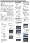
FQ2-S□□−□□□ Smart Camera Quick Start Guide Box Contents Mounting Base Sensor Four Mounting Screws (M3 × 8 mm) Instruction Manual Example 1 Here, measurements are performed when the trigger signal is input and the overall judgement is output. 1. Installation Quick Startup Guide (this document) Member Registration Sheet * 4 0 1 2 0 6 9 - 0 C * Brown Blue Power supply (24 VDC) GND (0 V) Indicates that processing Orange OUT1 (BUSY) is in progress. Overall judgement output Black OUT0 (OR) Pink TRIG Measurement trigger input (single) 1-1 Connections and Wiring 1 Connect the Sensor to the Touch Finder or Computer via the FQ-WN0□□ Ethernet Cable. System Overview Trigger Sensor When one unit is connected (control by parallel input/output) Touch Finder or PC Tool setup software 1 ms min. FQ2 PLC I/O Cable FQ Ethernet Cable Multiple Connections Touch Finder or PC Tool setup software The TRIG signal is not received while the BUSY signal is ON. Turn ON the TRIG signal while the BUSY signal is OFF. Sensor Touch Finder Ethernet connector 24-VDC power supply 2 When one unit is connected (control by Ethernet) Touch Finder or PC Tool setup software FQ2 (32 max.) Switching hub FQ Ethernet Cable Switching hub Standard RJ45 Ethernet Cable Standard RJ45 Ethernet Cable Standard RJ45 Ethernet Cable FQ Ethernet Cable Connect the trigger sensor, PLC, and power supply to each Sensor. I/O Cable Model number Remarks Sensor Touch Finder PC Tool FQ2-S□□-□□□ FQ2-D□□ --- This is the Vision Sensor. This is a setup console. FQ Ethernet Cable Standard RJ45 Ethernet Cable FQ-WN0□□ --- Connects the Sensor to the Touch Finder or computer. Connects the switching hub to the Touch Finder or computer. (STP (shielded twisted-pair) cable, category 5e or 6, impedance: 100 Ω) I/O Cable FQ-WD0□□ Connects the Sensor to the power supply, and external devices. 2. Saving Settings (1) Select the inspection items. (2) Register the measurement references. (3) Adjust the judgement parameters. 24 VDC Important Example 2 Here, a process switching signal is input from an external device to switch the scene. Brown Blue Power supply (24 VDC) GND (0 V) Indicates that processing Orange OUT1 (BUSY) is in progress. Gray IN0 Green IN1 Scene number Red IN2 input White IN3 Purple IN4 Command execution input Yellow IN5 Power supply (24 VDC) TRIG IN0 IN1 IN2 IN3 IN4 IN5 OUT0 (OR) OUT1 (BUSY) OUT2 (ERROR) IN0 to IN4 Blue I/O Inputs Operation 24 VDC 3. I/O Settings GND (0 V) Signal Function TRIG Measurement trigger input (single) IN0 to IN5 Command input Outputs OUT0 (OR) Scene number 5 ms min. Load 1. Checking and Adjusting Measurement Status 2. Measurement Settings OUT0 (OR) OUT1 (BUSY) OUT2 (ERROR) GND (0 V) TRIG IN0 IN1 IN2 IN3 IN4 IN5 Brown Pink Gray Green Red White Purple Yellow Black Orange Light blue The following steps are required to prepare the Sensor for operation. Installation Settings Testing 2. Mounting Black Orange Light blue Blue Pink Gray Green Red White Purple Yellow Processing Overall judgement PNP Flow of Operation 1. Image Setup Power supply (24 VDC) Load The PC Tool can be used instead of the Touch Finder. If you register as a member, you can download the free PC Tool as a special service to purchasers. Refer to the Member Registration Sheet for member registration procedures and the download procedure for special member software. 1. Connections and Wiring Brown ON OFF Use a no-contact output device (e.g., SSR or PLC transistor output) for the TRIG signal. If a contact (e.g., relay) is used, contact bound may cause the trigger to be input again during execution of a measurement. NPN 24-VDC power supply BUSY (OUT1) OR (OUT0) Connect the I/O Cable to the Sensor. FQ2 TRIG Ethernet connector The I/O Cable includes lines for the power supply and I/O. Connect the required lines. PLC Product 3. Starting the Sensor FQ-WN0□□ Ethernet Cable ON OFF IN5 ON OFF BUSY (OUT1) ON OFF 3 Indicates that processing is in progress. OUT2 (ERROR) Indicates an error has occurred. Connect a power supply to the Touch Finder. Note 24 VDC + Overall judgement output OUT1 (BUSY) 1 ms min. Processing − If a Touch Finder with an AC/DC/battery power supply is used, an FQ-AC AC Adapter (sold separately) or FQ-BAT1 Battery (sold separately) can also be used. 1 2 1-2 Mounting 1 The following initial display will appear when the Sensor is selected. Install the Sensor in the predetermined position. 2 Confirm the mounting position. Installing the PC Tool Use the optical diagrams in the User’s Manual to determine the Lens, camera installation distance, and detection range. Camera installation distance (mm) 1000 t0 t2 200 t5 100 t15 10 2 t10 10 35 Press [ To use the PC Tool, register as a member, download the PC Tool, and install the PC Tool on your computer. Use the following network settings on your computer if you connect the computer directly to the Sensor. If you connect the computer and Sensor through a hub using a DHCP server, the following IP address does not need to be set. • IP address: 10.5.5.101 • Subnet mask: 255.255.255.0 Example: Using a 3Z4S-LE SV-2514H Lens 100 Y axis of field of view (mm) The X axis in the above optical diagram represent the field of view (mm).*1 The Y axis represents the camera installation distance (mm) or WD (mm).*2 The macro ring thickness to be used is given as, for example “t5.0,” on the graphs. “t0” means that a macro ring is not required. “t5.0” means that you must use a 5-mm macro ring. ] and then [Shutter speed]. Setup Adjust the shutter speed with the slider at the bottom of the display. 2. Settings 2-1 Image Setup Make sure the image is stable and adjust the brightness and image input timing. 1-3 Starting the Sensor 1 2 Adjust the brightness. Adjust the shutter speed so that the Sensor can capture images of the measurement object at a suitable brightness. If the display is still dark, increase the gain. Bright Power ON the Sensor. 1 Power ON the Touch Finder. Dark Focus the image. Press [Camera setup]. Turn ON the power switch on the side of the Touch Finder, too. Press [OK]. Note Y Field of view X *1: The Y axis in the optical charts represents the height of the field of view. *2: The Y axis of the Compact Camera represents the WD. • Turning ON the [HDR] function improves the image quality for shiny objects. Refer to the User's Manual for details. 3 To use the PC Tool, click [Program] [OMRON] - [FQ] - [PC tool for FQ] from the Windows Start Menu. Camera The camera image will be displayed. Select the language to display on the Touch Finder. Adjust the image input timing. Adjust the delay from when the trigger is input until the image is input. Press [Trigger setup]. Macro ring t□ (mm) Camera lens Camera installation distance (mm) WD (mm) Measurement object Press [Trigger delay]. Field of view (mm) The higher the value, the better the focus. If you use an 3Z4S-LE SV-2514H Lens for a measurement object that requires field of view of 35 mm, the camera installation distance must be 200 mm and a 2-mm macro ring is required. Adjust the focus of the Lens. If more than one Sensor is connected, a display will appear to select the Sensor to be set. Select the Sensor. After the TRIG signal is input, images will be continuously input. Refer to the User’s Manual for the Lens models and dimensions. 2 2 Register the measurement reference. Press the parameter to set. Press [Teach]. Place the object that is to be used as the measurement reference in front of the camera. Move the rectangle so that the characteristic part for position compensation is inside it. Drag the rectangle to move it. Select the image that was taken with the best timing. Press [OK]. 4 Place the object that is to be used as the measurement reference in front of the camera. Move the rectangle so that the mark to be meaured is inside it. Drag a corner to size the rectangle. Adjust the image. Adjust the image that is taken by the Sensor to make it easy to measure. Here, the position is corrected by searching to enable measurements even if the position of the measurement object is not consistent. Press [Image adjustment]. Drag a corner to size the rectangle. Check the area, press the [OK] Button, and then press the [TEACH] Button. The characteristic part and reference position for position compensation will be registered. Drag the rectangle to move it. Press [OK]. You can add filter items to adjust the image to make it easier to measure. Refer to the User’s Manual for details. Check the area, press the [OK] Button, and then press the [TEACH] Button. Register the image as the measurement reference. 2-2 Measurement Settings Select items for the desired measurement and register an image as the reference for the measurement. Press an unused number and then press [Add pos. comp.] on the menu. 1 Lower limit Upper limit Press [OK]. The calculation settings can be used to perform calculations using the results of multiple inspection items. Refer to the User's Manual for details. 2-3 I/O Settings The data that is output to external devices and the input signal assignments can be changed. (Changes are not normally required.) For example, the following can be input or output. • Judgements for individual inspection items can be output. • Commands to register models can be input from an external device. • If you want to output data externally Refer to the User's Manual for details. Select the inspection items. 3. Testing Example to Register Search as the Messurement Method Press [Inspect]. Next, touch [Inspection]. Press an unused inspection item number and then press [Add item.] on the menu. Press [Back]. 3 Press [Search position comp.]. Adjust the judgement parameters. Press [Judgement]. Tests are made with some samples to see if correct measurements are possible. When Test Mode is entered, images are measured continuously. A trigger input is not required. Measurement results are only displayed. They are not output to an external device. 1 Press [Search]. Perform tests. Press [Test]. Then press [Continous test]. Press [Teach]. Adjust the judgement parameters while inputting sample images. Press the judgement condition parameter to adjust and set the upper and lower limits for an OK judgement. 3 Press [Graphics+Details]. Menu Structure Power ON Note Initial startup There are e six typ types of displays that can be used, as shown below. Press the e B Button and then press [Select display] to display the following selectio selections. Continuous measurements will be performed. Input images of some samples to see if the judgements are correct. Displaying the Most Recent Measurement Values Press [Back]. The best judgement parameters will be set automatically. Graphics Displaying Measurement Values Over Time Histogram Setup Mode Inspection items are set and adjusted. [Image] Tab Page Adjust images to the best input status. Camera setup 4. Operation 1 Trigger setup Image adjustment Switch to the Run Mode display. Variations in Measurement Values Press [Run]. Then press [Switch to Run mode]. Frequency Graphics + Details 2 Trend Monitor If correct judgements are not made, adjust the judgement parameters. [Inspect] Tab Page Select the inspection items and register the reference image and standard values. Inspection Items Search Color Data Labeling Shape Search II Press [ ]. Press [Adjust judgement]. Measurement values 2 Save the settings. All Results/Region Statistical Data Press [Yes]. Press [ ]. Press [Auto judgement]. Sensitive Search OCR Edge Position Bar code Edge Width 2D-Code Edge Pitch 2D-Code (DPM) Area Teach Judgement FQ2-S4- [In/Out] Tab Page Make settings to output measurement results. Log setting 3 You can use prepared samples to automatically set the best judgement parameters. Input a sample of a good object and press [OK Teach]. Input a sample of a bad object and press [NG Teach]. Repeat these steps for at least two samples each. I/O setting Execute measurements. Measurement values since power was turned ON Measurements will be executed according to the trigger signal input. And the result of measurement will be output to an external device. I/O monitor [Test] Tab Page Test and adjust the set inspections. Continuous test Note Save data • To return to the Setup Display, press the e [Sensor settings]. e • To switch to another Sensor, press the [Switch sensor]. B Button and then press B Button and then press When a Sensor that is already set up is connected Run Mode The inspections that were set on the Setup Mode are used to perform measurements. 4


