1
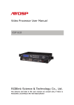
Video Processor User Manual
VSP 112
RGBlink Science & Technology Co., Ltd.
The pictures and data in the user manual are consult only, if there is
fluctuation, according to the real object please!
CONTACT US
Headquarter: S603 Weiye Building Torch Hi-Tech Industrial Development Zone
Xiamen,Fujian Province, P.R.C
Shenzhen office: Room A05, Floor 4, Building 24, Industry factory Nanshan
Science & Technology Park, Shenzhen, Guangdong Province, P.R.C
Tel: +86-592-5771197
Fax:+86-592-5771202
E-mail:[email protected]
http://www.rgblink.com
Revision
Format
Time
ECO#
Description
Principal
1.0
2011-06-09
0000
Release
Bing
CONTENT
1.0
2.0
3.0
4.0
5.0
6.0
7.0
8.0
9.0
Safety ........................................................................................... 1
Specification .................................................................................. 2
Parameters .................................................................................... 4
Connectors and cables..................................................................... 6
4.1 VSP 112 connectors and signals .................................................. 6
4.2 VSP 112 size and installation ...................................................... 8
Front Panel Keyboard Operation........................................................ 9
5.1 VSP 112 Operator Guideline........................................................ 9
5.2 VSP 112 Video Processor Menu...................................................10
Communication Software Guideline ..................................................16
6.1 Install Software .......................................................................16
6.2 Run AVDSP Console ..................................................................19
FAQ .............................................................................................31
7.1 No output in target display ........................................................31
7.2 VGA input could not work with AVDSP Console .............................31
7.3 DVI input could not work with AVDSP..........................................31
7.4 User settings can not save.........................................................32
How to control processor with console softwore by USB .....................33
Appendix ......................................................................................37
9.1 AppendixⅠDownload the IP software ..........................................37
1.0 Safety
The general safety information in this summary is for operating person.
Any requirement, please feel freely to contact our service engineer.
Power Source
This product is intended to operate from a power source
between 85~265 volts rms . This product is only workable under
correct power condition, which is already mark on the back
panel of the power.
High Voltage
There are many high voltage components inside.
Do not Remove Covers and Panels
Do not remove Covers in any conditions. There are not any
spare components inside for maintenance, so do not maintain
this product by userrselves, any requirement, please feel free to
contact our service engineer. Keep heavy device from power
cord.
Grounding the Product and Use the Proper Fuse
This product is grounded through the grounding conductor
of the power cord. To Avoid electrical shock, plug the power
cord into a properly wired receptacle before connecting to the
product input or output terminals.
Keep away from Magnet, Motor, TV and Transformer.
Guard Against Damp
Keep using inside clean and dryness environment, once the
device get wet, must remove power cord right now.
Keep away Exploder
Do not operate the device inside dangerous and easy
explosive gas, which it may make fire, blast or something
without expectation.
Keep away Pour Liquid and Fragment
It is forbid to pour liquid, metal fragment or anything else
inside this device to avoid fire and other accident. Once that
happens, must remove power cord and try to make it clean
before power on again.
VSP 112 User Manual
Doc. No:RGB-RD-UM-V112E001
1
2.0 Specification
AVDSP series video processors are designed by the latest high
performance image processing technology. AVDSP can handle following video
without limit, include CVBS(Composite)、S-Video (YC)、YCbCr、YPbPr、RGBHV
(VGA)、DVI-D、HDMI、SDI(SD-SDI、HD-SDI) and USB.
Compare table of AVDSP as following.
VSP 112 User Manual
Doc. No:RGB-RD-UM-V112E001
2
VSP 112 User Manual
Doc. No:RGB-RD-UM-V112E001
3
3.0 Parameters
Composite BNC Input
Number of Inputs
2
Supported
Standards
PAL/NTSC
Signal Level
1Vpp±3db
Number of Inputs
480i,576i
(0.7V Video+0.3v Sync ) 75 ohm
VGA DB15 Input
Number of Inputs
1
Connector
Standard DB15 socket
Supported
Standards
VGA-UXGA
Signal Level
R、G、B、Hsync、Vsync:0 to1Vpp±3dB
(0.7V Video+0.3v
Sync ) 75 ohm
black level:300mV Sync-tip:0V
Support
Standards
input
VGA-UXGA (800*600@60, 1024*768@60, 1280*1024@60,
1440*900@60,1600*1200@60)
DVI Input
Number of Inputs
1
Connector
Standard DVI-I socket
SMPTE : 625/25 PAL, 525/29.97 NTSC, 625/50p PAL,
Supported
Resolution
525/59.94p
NTSC:1080i50,1080i59.94/60,720p50,720p59.94/60
VESA : 800×600×60Hz , 1024×768×60Hz ,
1280×768×60Hz,1280×1024×60Hz,1600×1200×60Hz,
Signal Level
1920×1080×60Hz
TMDS pwl,single pixel input,165MHz bandwidth
Standard
HDMI 1.3
USB Input
Number of Inputs
1
Connector
Standard USB Connector
Supported
Standards
Image: JPGE,BMP,PGN
Audio: WMA,MP3,M4A(AAC)
Video: MPEG2,MPEG3, MPEG4,H264, RM,RMVB,MOV,
MJPEG, VC1,DivX,FLV
DVI Output
Number of Inputs
1
Connector
Signal Level
Standard DVI-I Interface
TMDS pwl, 165MHz bandwidth
Supported
Standards
VESA:800×600×60Hz,1024×768×60Hz,1280×768×60Hz,
1280×1024×60Hz,1440×900×60Hz,1400x1050x60,
VSP 112 User Manual
Doc. No:RGB-RD-UM-V112E001
4
1920×1080×60Hz,1600x1200x60 Hz.
VGA Output
Number of Inputs
1
Connector
Standard DB15 socket
Supported
Standards
VESA:800×600×60Hz,1024×768×60Hz,1280×768×60Hz,
1280×1024×60Hz,1440×900×60Hz,1400x1050x60,
1920×1080×60Hz,1600x1200x60 Hz.
R、G、B、Hsync、Vsync:0 to1Vpp±3dB (0.7V Video+0.3v
Signal Level
Sync ) 75 ohm
black level:300mV Sync-tip:0V
Function
Source Switch
support quick switch between all the inputs
Yearly hardware
Schedule
Support yearly, monthly, weekly and daily schedule
function without PC runs to control in real time
Extras
Communication
RS232 USB TCP/IP
Power Supply
85-264V 2A IEC-3
Working
Environment
0°C~45°C
Stored
Environment
10% to 90%
Product Warranty
1 year
VSP 112 User Manual
Doc. No:RGB-RD-UM-V112E001
5
4.0 Connectors and cables
4.1 VSP 112 connectors and signals
1,2,6,7: Gigabit copper port, connect to LED screen;
3,8: Gigabit Transmitter card power interface, not use inside case;
4,9,12: USB: No. 4 and 9 are the USB interface to control the sending card by
LED studio or control software,No. 12 are the USB interface to control
processor by AVDSP PC software ;
5,10: Gigabit Transmitter card DVI input,connect to DVI output of VSP 112.
(This Connection does not comment hot-plugging);
11: dial switch, more details please refer to Appendix II
13,14: Composite input interface,Composite BNC. YCbCr compatible. Used to
input composite signal from DVD, Set-top box, HD player and so on
(PAL, NTSC, SECAM compatible);
15: USB input interface, used to player media files from disk with USB connect
or. Such as USB disk, Portable Hard Disk
16: DVI input interface. Input the video signal from computer, DVI signal
generator. Connect to the DVI 1 interface on VSP 112(This Connection
does not comment hot-plugging);
VSP 112 User Manual
Doc. No:RGB-RD-UM-V112E001
6
17: VGA input interface, DB-15, used to support Analog RGB input; Connect to
the VGA 1 interface on the VSP 112.
18: DVI output interface. connect to the monitor or LED screen which has DVI
interface. (This Connection does not comment hot-plugging)
19: VGA output interface, connect to the monitor, projector and so on;
20,21: Switch and power. It must use IEC-3 power line. Always ground to
avoid electric shock.
VSP 112 User Manual
Doc. No:RGB-RD-UM-V112E001
7
4.2 VSP 112 Size and installation
VSP 112 User Manual
Doc. No:RGB-RD-UM-V112E001
8
5.0 Front Panel Keyboard Operation
Insert power cord and push power button to ON position. LCD module on
the front panel will show RGBLINK and go into self verification before it load the
last setting config and send the processed image to the target display or device.
For the first running,CV1 input is the default input source. With the front panel
operation, users can operate the equipment with buttons and menu displayed
on LCD module.
5.1 VSP 112 series Operator Guideline
VSP112 front panel as following:
1. LCD module ;
2. Keyboard;
SEL: Push to confirm the current choice item;
UP: Push to select up items in LCD menu;
DOWN: Push to select down in LCD menu;
CV1: Switch to composite1 input;
CV2: Switch to composite 2 input;
VGA:
Switch to VGA input;
DVI:
Switch to DVI input;
USB: Switch to USB input;
OUT:
Push to select the output format by using the UP and DOWN.
FS: Switch to select full screen or zoom view,just for single picture mode;
SAVE1: Switch to use the user-defined mode1;
SAVE2: Switch to use the user-defined mode2;
SAVE3: Switch to use the user-defined mode3;
SCALE: Push to go to between HsizeÆVsizeÆHPOSÆVPOS;
VSP 112 User Manual
Doc. No:RGB-RD-UM-V112E001
9
MENU: Push to go to main menu;including device information,recall,language
and Alpha.
SAVE: Push to save current config.save1/save2/save3.
5.2 VSP 112 Video Processor Menu
System menu as follows;
RGBLINK
视诚科技
亮彩系列
AVDSP Series VSP 112
Wait Init Network…
Devices can be connected to the LAN network by CAT5, if not, it will prompt:
DHCP Failed as shown;
DHCP Failed
When the device accesses to the network ,it will be get an IP address
automatically, menu as shown:
IP Address
192.32.0.100
Push【MENU】will always go to main menu
Push Menu, system main menu as shown;
>VSP 112
*Dev Info
Recall
↓
Push the right and left direction key to select the left or right menu. Before the
menu item, if there is a * sign, means the menu item has been selected, you
can push the Sel key to enter it. The first line shows VSP112.Select Dev Info,
VSP 112 User Manual
Doc. No:RGB-RD-UM-V112E001
10
it shows current input signals. If there is a composite input to CV1, the NO
INPUT will show as the input composite format, such as 720*576i. As shown;
INPUT: CV1
NO INPUT
Push UP/DOWN to check current output format.
Output Format:
1920x1080x60
Push UP/DOWN to check current software version;
Software Version
1.0
Push UP/DOWN to check current Video Processor serial number to get more
available service and support;
RGBlink
> SN:J0004
Push UP/DOWN direction, select RECALL to recall factory reset.after successful
factory reset you will see the menu as shown;
Reset Finished!
Push UP/DOWN of the Menu to set LANGUAGE and HDMI output;
>VSP 112
*Language
HDMI OUT
Push UP/DOWN to select and enter submenu accordingly; enter LANGUAGE
sub menu, as shown;
*Language
> English
Select:
中文
Select HDMI OUT to set DE and push UP/DOWN to choose output format. as
shown;
>HDMI1
*DE Setup
HDMI/DVI
VSP 112 User Manual
Doc. No:RGB-RD-UM-V112E001
11
Select to enter DE setup mode, push UP/DOWN to choose ON/OFF, SEL ON to
set, which will check ON item with “*”.
>HDMI1
*ON
DE On/Off
Push UP/DOWN to go to DE H Start , DE V Start, DE Width or DE Height, push
UP/DOWN to change the values of them seperately;
>HDMI1
>192
DE H Start
>HDMI1
>43
DE V Start
>HDMI1
>1920
DE Width
>HDMI1
>1080
DE Height
in HDMI mode, push UP/DOWN to choose output format. as it shown;
>HDMI1
DE Setup
*HDMI/DVI
SEL to go into HDMI/DVI, push UP/DOWN to choose the output formats of
HDMI/DVI.
>HDMI1
*HDMI
HDMI/DVI
Push UP/DOWN to enter main menu to setup time and calendar.
>VSP 112
*Time
Calendar
Push SEL to set time.
Time
> 00:00:20
Push UP/DOWN direction to live time set-up. it shows * signal, the current
revised will flash;
VSP 112 User Manual
Doc. No:RGB-RD-UM-V112E001
12
Time
*00:00:20
Push SEL to set Calendar, the left side shows calendar, right side shows the
English Abbreviation of the day of the week.
Calendar
>2010/01/01
Fri
Push UP/DOWN to active the time, it shows * signal, the the inter-flash means
currently to change, push UP/DOWN to change the flashing calendar and the
day of week;
Calendar
*2010/01/01
Fri
Push UP/DOWN of the Menu to set Scale and Advanve;
>VSP 112
* Scale
Advanve
Push SEL to set scale;
Scale A Pos X:
>0
Scale A Pos Y:
>0
Push UP/DOWN to set coordinates.
Scale A Width:
>1920
Scale A Height:
>1080
Or Push【Scale】to set scale
Touch UP / DOWN, find Advance in the 【MENU】to do advanced split screen set;
VSP 112 User Manual
Doc. No:RGB-RD-UM-V112E001
13
>VSP 112
Scale
*Advanve
Click on SEL to enter into Advanced settings, Touch UP / DOWN to set the
coordinate, width and height, as following pictures:
Screen Pos X:
>0
Screen Pos Y:
>0
Screen Width:
>1920
Screen Height:
>1080
In the Aspect Ratio mode, the device offers 3 aspect ratio, except for above
three normal modes, there are also:
Aspect Ratio:
*4:3
Aspect Ratio:
*16:9
Push FS to switch between full screen and samll display size which defined by
screen parameters;
Picture Mode
Full Size
Picture Mode
Screen Size
Push OUT to enter output format menu; push UP/DOWN to choose different
output formats, and SEL the needed output format.
Output Format:
>1920x1080x60
VSP 112 User Manual
Doc. No:RGB-RD-UM-V112E001
14
Push SAVE menu, it turns SAVE1/SAVE2/SAVE3
Save Setting To:
Press ESC To Exit
Push Save1 to save in the save1 mode;
Save Setting To:
SAVE1
Finished!
Save successfully and push SAVE1 to call SAVE1 user config mode;Push SAVE2
and SAVE3 to call another two seperately.
added SAVE notice function;
when push SAVE, all SAVE1/SAVE2/SAVE3 will light on,users
should push SAVE1/SAVE2/SAVE3 to save successfully.
VSP 112 User Manual
Doc. No:RGB-RD-UM-V112E001
15
6.0 Communication Software Guideline
AVDSP video processor is very easy to be configured with user friendly
interface, support drag and drop operation for edit and display. User can also
customize with schedule function.
6.1 Install Software
Dual click AVDSP.exe to run install, select Chinese or English version for
end user,and click “select ” to go on.
Please read carefully the license of agreement before installing VSP 112
console software, select the "Agree" to continue; select "Disagree" to quit, as
shown:
VSP 112 User Manual
Doc. No:RGB-RD-UM-V112E001
16
After agree to the agreement, user can select install directory in the next
dialog, and click next to install software to default directory “C:\Program Files”
directly.
Click “next ”to go on.
Click “next ”to go on.
VSP 112 User Manual
Doc. No:RGB-RD-UM-V112E001
17
Click “finish” and ready to run AVDSP console.
VSP 112 User Manual
Doc. No:RGB-RD-UM-V112E001
18
6.2 Run AVDSP Console
First run software will auto detect device in serial or networks by Comm
port and pro-define IP address.
The software as following:
VSP 112 User Manual
Doc. No:RGB-RD-UM-V112E001
19
z
Setup Communication
AVDSP Console support COM port or Ethernet (UDP) to access AVDSP.For
to close COM Port. Click
the first running ,user must click the
to
change the COM Port and the Baudrate.
Serial: user can make choice between exist com ports and baud rates;
default Baudrate is 9600.
Ethernet: user can fill any number less than 1023 in Local Port. The
Remote Port must be 192.168.0.100 and the Remote Port must be 1000.
The COM Port is decided by operation system. Right click “my computer”
icon on desktop, select HardwareÆDevice Manager in the system attributes
dialog. The COM in red in the picture is the COM user can make choice.
Then click
to open COM.
will display after
success to connect the COM.
VSP 112 User Manual
Doc. No:RGB-RD-UM-V112E001
20
If AVDSP console success to detect device in chain, the software version,
device core version, firmware version and serial number will display on the
bottom right corner of the screen.
5
How to use
Operator can check parameters by software.
:Save script. Save current user config parameters as script.
:Open script. User can open saved script.
:Import template. There are six templates for user.
VSP 112 User Manual
Doc. No:RGB-RD-UM-V112E001
21
:Save template. Save the current config, there are six templates for
user.
:Option. User can choose open device when start and using script
saved before or execute schedule edited before when start.
If user choose open device when start, user can use last run config, use
script file or none when user start. User can click
to choose which script
user want to open.
If user choose execute schedule when start, the next dialogue will display
when software run.
VSP 112 User Manual
Doc. No:RGB-RD-UM-V112E001
22
:Language. The software supports Chinese and English version. The
picture following is the Chinese dialogue.
:Exit.
z
Communication
: Open COM.
: Close COM.
: Set COM.
: Search Device
z
Device
:Synchronization; Click the button to synchronize setting parameters
on device and PC software, as well as data for EPROM splitting mode.
:Save to flash
VSP 112 User Manual
Doc. No:RGB-RD-UM-V112E001
23
:Load form Flash.
:Factory setup;Click this button to recall the factory setting.
:Advance, for administrator control.This is only open to Technical
Engineer, please contact us to get password if needed.
: VGA Adjust: push this button to set auto adjustment for VGA inputs
z
Help
:Help. Click to open helps file.
VSP 112 User Manual
Doc. No:RGB-RD-UM-V112E001
24
:About. Click to show the version number of Software and Company
Contact information.
z
Output resolution: user can choose different output resolution by
selecting from pull down list.
z
Input resolution:it will show resolution of current input source after
communication finish.
z
Aspect Ratio: user can push pull down menu and select to switch between
4:3, 16:9 and normal;
z
Input: the white area displays the name of input interface when the
mouse is over the interface picture on the left. The orange pane means
current selected interface.
VSP 112 User Manual
Doc. No:RGB-RD-UM-V112E001
25
z
Screen parameter:
Screen parameters are used as reference for FS function, after set the
parameters, when user push FS button on the front panel or the software, the
image will switch to screen parameters setting size if originally display as full
screen, and switch to full screen if originally display as screen parameters
settings.
z
Images: User can scale the images by entering the data or dragging
image to zoom out. And enter data by Set button push will set Zoom and
Crop. Zoom and Crop function are only valid in administrator mode.
z
Display Toolbar: there are two display modes,choose “dynamic Video” to
play video normally, choose “ static current” to freeze the current frame of
the video.
z
Output: user can customize the brightness and the contrast.
z
Media player menu: click the files in the list can play the media files
directly, and can also select the files need to play, VSP 112 will run the files
according to the index value of the files. And user can schedule when to
play after refer to the play time values.
VSP 112 User Manual
Doc. No:RGB-RD-UM-V112E001
26
z
Display: user can customize image or images position and size just by
drag and drop image (images) in this area. This process can sync to the
parameters in images toolbars.
As following,There are 1~3 user Mode for you to recall.
z
Log: user can save or delete the operate log file
VSP 112 User Manual
Doc. No:RGB-RD-UM-V112E001
27
Additional functions
z
Device IP
Users can set equipment IP, Usually used under the condition of one
computer control or remote control several computers.
z
USB Schedule function
VSP 112 User Manual
Doc. No:RGB-RD-UM-V112E001
28
User can use “USB media player schedule setting” menu to run the source
switch or media files schedule design. Now it can support max 14 schedule
rules.Following is the step to design the schedule.
1. Set the start running date and stop running date on Date position;
2. Set the week day in Week setting position;
3. Turn on the schedule switch by check the “Time Switch”;
4. Set the play time for each file (which work by play index);
5. Set the repeat time for each file, which can be control from pull down menu
or input times directly;
6. Set the input source control in Play Source position;
After setting finish, click “OK” to start to run the schedule function.
VSP 112 User Manual
Doc. No:RGB-RD-UM-V112E001
29
z
Device Date Time
Remember to set the Device Date Time to the same to the local time, and after
set, can check also on the front panel LCD module.
After factory reset, all schedule function need to set again.
VSP 112 User Manual
Doc. No:RGB-RD-UM-V112E001
30
7.0 FAQ
7.1 No output in target display
1)Check the output config of the input video
2)Check the input channel config is ok. For example. The composite 1
interface is connected to the composite interface of video source
3)Check the connection of output is ok
4)Check the target monitor or display is not destroied or power down
5 ) Check the output resolution of AVDSP is not out of the maximal
resolution of target display
6)Any requirement ,please feel free to contact out customer service
engineer
7.2 VGA input could not work with AVDSP console
1)Check input source output is ok
2)check VGA input resolution is not of AVDSP Console support list , as
following the biggest input resolution is 1024*768*60Hz
3)Check AVDSP console work in VGA input mode
4)Through the automatic gain correction phase output setup menu
5)Any requirement ,please feel free to contact our customer service
engineer
7.3 DVI input could not work with AVDSP
1)Check DVI source is ok
2)check DVI input resolution is not of AVDSP Console support list , as
following the biggest input resolution is 1024*768*60Hz
3)Check AVDSP work in DVI input mode
4)Check the connection between AVDSP and DVI source is correct. Restart
DVI sourse and check output
5)Any requirement , please feel free to contact our customer service
VSP 112 User Manual
Doc. No:RGB-RD-UM-V112E001
31
engineer
7.4 User settings can not save
VSP 112 supports multi config mode. For multi config mode , the
equipment starts to work automatically with the SAVE1 mode .According to
different equipments ,you can solve the problems that modes can’t be saved
by the following steps.
VSP 112
1)Comfirm to press the “SAVE”button, then press “SAVE1”.or “SAVE2”,or
“SAVE3”,that will save the current operation mode to the “user mode1””user
mode2”or “user mode3” after that ,push button “SAVE1”.or “SAVE2”,or
“SAVE3”,it will call out the corresponding setting of user-mode if that the
saving is successful
2)After saving process, user should not do factory reset or any saving
operation to user mode 1 otherwise,”SAVE1”will be over write.
3)Recognized in the implementation of the save operation, the user is not
saved for other operations again
Any requirement , please feel free to contact our customer service engneer
VSP 112 User Manual
Doc. No:RGB-RD-UM-V112E001
32
8.0
How to control processor with console by USB
1. install the driver
Connect the USB cable to the PC and the video processor .turn on the VSP
112,for the first time to use USB , the PC will remind finding the new hardware
and ask to install the driver for this new driver
Install from the list or specified location ,press “NEXT”
Press “browser” to find the driver, and press “NEXT”
VSP 112 User Manual
Doc. No:RGB-RD-UM-V112E001
33
When the installation finish,can go to check the installed COM port inside
the device mangement ,as following picture show”
VSP 112 User Manual
Doc. No:RGB-RD-UM-V112E001
34
2.Install the console software, and run after install,shows the interface of the
console as following
: Set the RS232 as installed just now, and set the VSP 112 Boud Rate
to be :115200
VSP 112 User Manual
Doc. No:RGB-RD-UM-V112E001
35
Press
to start RS232 communication, when there is green point in
the right down corner showing on the sofwware, it means the communication
is ok ,and you can use the software to control the device now ;
If power off during communication,should close the port by
first , and plug in out of the USB and do communication
again
VSP 112 User Manual
Doc. No:RGB-RD-UM-V112E001
36
9.0 Appendix
9.1 Appendix I Download the IP sofeware
Turn off the power , take the two coding switch to “ON”sate as below :
Connect one side of the USB download line to the UBS interface on the video
processor,and the other side to be connected to the UBS 2.0 interface on the
PC.
Double click
:to run flash magic , setting as below :
First, users can choose the right serial port ,set the baud rate to 9600, choose
LPC2368, and to load the aim document(hex.document )of Ipboard upgrading
secondly , confirm the two option box by tick.
Finally,click the “start”button
VSP 112 User Manual
Doc. No:RGB-RD-UM-V112E001
37
After download , exit the program ,turn off the power ,tack the two coding
switch back ,as below restart the equipment power ,check if the equipment
work normally .
Go to the link to download flash magic toolset.
http://www.flashmagictool.com/download.html&d=FlashM
agic.exe
VSP 112 User Manual
Doc. No:RGB-RD-UM-V112E001
38