1
Please read through this user’s manual to ensure correct usage of the controller and keep it handy for quick
reference.
CONTENTS
1. Notice ............................................................................................................................... 2
2. What is on the Front Panel? ......................................................................................... 3
3. Installing the Controller ................................................................................................ 4
4. Panel Cutout Dimensions and External Dimensions .................................................. 5
5. Wiring .............................................................................................................................. 6
6. Hardware Specifications ................................................................................................ 9
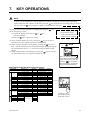
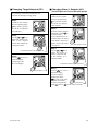
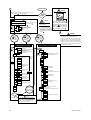
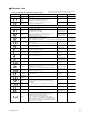
7. Key Operations ............................................................................................................. 11
8. Troubleshooting ............................................................................................................ 20
■ Checking Package Contents
Before using the product, check that its model & suffix codes are as you ordered.
Model and Suffix Codes
Model
Suffix code
UT150
UT152
UT155
Control output for standard
type (or for heating)
Control output for cooling
Description
Temperature controller
–R
–V
–A
Relay output (time-proportional PID or on/off control)
Voltage pulse output (time-proportional PID)
4 to 20mA output (continuous PID)
N
R
V
A
No cooling output (standard type)
Relay output (time-proportional PID or on/off control)
Voltage pulse output (time-proportional PID)
4 to 20mA output (continuous PID)
/AL
/HBA
/EX
Option
/RET
/RS
/V24
Alarm outputs (2 points)
Heater disconnection alarm (includes optional /AL function)
SP1/SP2 switching, starting of timer, and RUN/STOP
switching by external contacts
PV retransmission output in 4 to 20mA
Communication function
Power Supply 24V DC / 24V AC
Note:When specifying the /RS option, be sure to order the required number of copies of
Communication Functions User’s Manual separately.
Check the package contents against the list below.
• Temperature controller .......................... 1
• Mounting bracket ................................ 1 for UT150
2 for UT152, UT155
• User’s manual (IM 05C01E12-01E) .......... 1
IM 05C01E12-41E
1