1
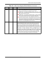
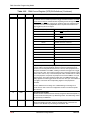
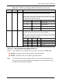
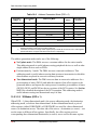
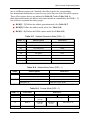
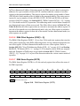
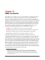
DMA Controller Programming Model
Table 10-2 Interaction Between the DSR and DCO in Mode A
Before the Transfer
After the Transfer
DSR
DCO
DSR
DCO
S
5
S+1
4
S+1
4
S+2
3
S+2
3
S+3
2
S+3
2
S+4
1
S+4
1
S+5
0
S+5
0
S+6
5
10.5.3.2 DMA Counter Mode B—Dual Counter
Figure 10-3 shows that in DMA Counter Mode B, which is useful for two-dimensional
block transfers, the DCO is separated into two sections: DCOH[23 –12] and
DCOL[11– 0] bits.
23
12 11
DCOH
0
DCOL
Figure 10-3. DMA Counter Mode B Layout
Before each DMA transfer, DCOH and DCOL are tested for zero, and the following
actions occur based on the test results:
■
DCOH > 0 and DCOL > 0
A transfer is initiated with an address equal to the address register. Then DCOL is
decremented by one and the address register is incremented by one.
■
DCOH > 0 and DCOL = 0
A transfer is initiated with an address equal to the address register. The address
register is incremented with the specified offset register, DCOH is decremented by
one, and DCOL is loaded with its preloaded value.
■
DCOH = 0 and DCOL = 0
The last transfer is initiated with an address equal to the address register. The
address register is incremented with the specified offset register, and both DCOH
and DCOL are loaded with their preloaded values.
The number of transfers in this mode is equal to (DCOL + 1) × (DCOH + 1). For example,
assume DCOH is preloaded with the value 1, DCOL is preloaded with the value 2, DOR is
10-12
DSP56300 Family Manual
Motorola