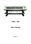
1
Operation Manual FY-8180C/1808C Thank you very much for purchasing INFINITI In order to use INFINITI correctly and safely and understand this product’s capability, please read this manual carefully. The manual includes equipment structure, description, technical parameters, operation manual, safety information, application of software, etc. This manual is subject to change without notice. Contents herein contained are believed to be correct, however, please contact us if you find any error or something not clear enough. All copyrights 2003 Infiniti. All rights reserved. November 11, 2004 Version 1.0 FY-8180/1808C User Manual Index Index Chapter 1 1.1 1.2 1.3 1.4 1.5 1.6 Precaution About manual Cautions Tips for Operation of Printer Tips for Operation of Ink Cartridge About PC Warning, Caution and Attention Chapter 2 Production Introduction 2.1 Technical Parameters 2.2 Parts 2.2.1 Parts of printer 2.2.2 Explanation of Operation Panel 2.3 Printer Status Display Chapter 3 Printer Assembly 3.1 Printer assembly 3.2 Connect With Power 3.3 Port of Printer Chapter 4 About Menu 4.1 Menu 4.1.1 Online Mode 4.1.2 Offline Mode 4.2 Explanation Chapter 5 Basic Operation of Software 5.1 Software Installation 5.1.1 RIP Installation 5.1.2 Printer Driver Installation 5.2 Application of Printer Driver 5.2.1 Enter TRY 5.2.2 Print Setting 5.2.3 Printer Parameter Setting 5.3 Equipment Adjustment 5.3.1 Enter TRY 5.3.2 Print head Adjustment 5.3.3 Rectangle Adjustment 5.3.4 Four Colors Overlapping Adjustment 5.3.5 BID Adjustment 2 FY-8180/1808C User Manual Index 5.4 Basic Operation of RIP Chapter 6 Normal Printing Procedure, Head Cleaning and Maintenance 6.1 Printing Steps 6.2 Print head Usage And Maintenance 6.2.1 print head Usage 6.2.2 Positive Pressure Cleaning 6.2.3 Print head cleaning and maintenance 3 FY-8180C/1808CFA User Manual Precaution Chapter1 Precaution 1.1 About Manual This manual is for the users or technician who operates the Printer FY-8180C/1808C. Manual describes preparation and operation procedure. Before using the printer, make sure you are familiar with the content of the manual, especially some key chapters. Please operate the printer according to the manual. Please pay attention to the cautions and guides marked on the printer. Please contact our technology support department for any question. 1.2 Cautions: 1. 2. 3. 4. 5. 6. 7. 8. 9. 10. 11. 12. 13. Do not put the machine at following places: (1) Unstable place; (2) Inclined place; (3) Some place easy to vibrate or shake; (4) Some place where the temperature and humidity change dramatically. (5) Exposed to sunshine, strong light or heat. (6) Moisture or dusty place (7) Grounding end of phone line or illumination line. Leave enough space around the printer to ensure the good ventilation. Place the printer near the outlet in order to plug it conveniently. Do not clog the aperture on the cover of printer. Do not insert anything into the dent of printer, and avoid splashing fluid into it. Only use the type of power specified on the tag of printer. Connect all the equipment to a properly grounded socket. Avoid the socket in the same circuit with copy machine or air conditioner. Avoid using wall switcher or switch controlled by an automatic timer. Keep your computer clear from the latent source of electromagnetism disturbance, for instance, loudspeaker or wireless phone. Do not use the damaged or worn cable. If using additional cable, please make sure that total amperage of the equipments connecting with cable shall not exceed the amperage of the power supply. What’s more, the amperage of all equipment connecting with wall socket does not exceed the amperage of wall socket. Do not try to repair the printer by yourself. When facing the following situations, shut off the power and ask experienced technician for help: (1) If the power cable or plug is damaged; (2) If some fluid splashes into the printer; (3) If printer falls down or cover is broken; 1 FY-8180C/1808CFA User Manual Precaution 14. If the printer does not work well or has an obvious change in property, do not put anything heavy on it. Do not incline it or put it close to the wall. Do not put it upside down. Do not block the ventilation holes. Do not use the damaged cable. Never insert or remove the plug with wet hands. 15. Do not remove the ink cartridge. Open and close the lid of ink cartridge carefully. When initializing the printer, do not move media bar. Do not use the thinner, benzene, alcohol, etc to clean the surface of printer. Do not open the cover fixed by screw. Do not use knife to cut anything hard. 16. Disconnect the power before cleaning. Keep the printer horizontal when moving. 17. Use cuprous cable for grounded cable of power supply and this cable should be put more than 65cm underground. 1.3 Tips for Operation of Printer Never use fingers to move print head. It may cause damage to the printer. Always use the power switch to turn off the printer. Never pull out the plug or data cable before power is shut off. Keep the print head at its origin position and fix before moving. 1.4 Tips for Operation of Ink Keep the ink clear from child. Do not let the child touch or drink ink. If ink splashes onto skin, wash with soap and water. If into eye, wash with water immediately. Store ink at 10~40°C. 1.5 About PC Operation System: Windows NT4.0/Windows 2000 or above. Configuration reference: CPU RAM Hard disk for installation Hard disk available O/S Monitor Others Minimal Pentium III 500MHz 128MB 500MB 2GB Windows2000/XP 600X800 16colors CD-ROM, USB port for dongle Optimum Pentium 4 1500MHz 256MB 500MB 4GB for processing files Windows 2000/XP 600X800 16colors CD-ROM, USB port for dongle The configuration does not affect the printer more than the software RIP does. However, it is safe to say you can get higher efficiency and better effect with the optimum configuration. 1.6 Warning, Caution and Attention Warning: 2 FY-8180C/1808CFA User Manual Precaution Do as what it says to avoid any injury. Caution: Be sure to observe it to avoid any damage. Attention: Contain some important information and helpful tips for operation. 3 FY-8180C/1808C User Manual Production Introduction Chapter2 Production Introduction 2.1 Technology Parameters Model FY-8180C/1808C Print technology 4 colors Piezo print head (nozzle: 8X126) Resolution 200dpi、400dpi Printing quality Photo like Max print width 1840mm Max media width 1860mm Ink Solvent Cyan, Magenta, Yellow, Black Ink-supply By ink pump Media Media feeding Normal lamp fabric, instant plaster and cold-back up film etc. By roll or sheet (bigger than A4 or 210mm wide) Media processing Auto feeding and take-up roller Print head height 2mm-5mm from media adjustable Print head cleaning Outside cleaning Interface USB Print language HH-RTL Noise Printing≤60dB/waiting≤40dB (ISO7779) Printer size (incl. ink tank) Length 3040mm×width 740mm × height 1280mm/150kg Package size Length 3160mm×width 760mm × height 750mm/210kg Power AC 100 ~ 240 V Frequency 1000W O/S WIN2000/XP Working environment Temperature: 20°C ~ 28°C 4 FY-8180C/1808C User Manual Production Introduction 2.2 Parts 2.2.1 Parts of printer 1 3 4 5 13 12 6 7 8 10 15 2 9 11 14 16 1-wheel controller 2-supporter 3-power switch 4-power port for printing 5—Switch for heating controller 6—leakage protector 7-- port for printing cable 8-waste ink tank 9-media feeding roller 10—ink cartridges 11—media feeding and take-up framework 12— switch for positive pressure clean 13—light switch 14—media feeding control box 15— media 16—media feeding sensor 1. 2. 3. 4. 5. 6. 7. 8. 9. 10. 11. 12. 13. 14. 15. Wheel controller: lift up or down the controller to install media Supporter: support the whole printer Switch power: power of printer Power port for printing: power of printer Switch for heating controller: for heating Leakage protector: to prevent leakage Port of printing cable: connect with inside data card on computer, or connect with USB. Connect with USB port by cable. Waste ink tank: to collect the waste ink Feeding roller: hold media which is not printed yet Ink cartridge: for C, M, Y, K ink Media feeding and take-up framework: include feeding roller, control panel and holder etc. Switch for positive pressure clean: to clean the print head using positive pressure Light switch: switch for turning on the light when clean the print head Media feeding control panel: for media feeding and take-up control Media: Media for printing 5 FY-8180C/1808C User Manual Production Introduction 16. Media feeding and take-up sensor: control media feeding and take-up automatically 2.2.2 Explanation of Operation Panel No. 1 Name ONLINE Function Shift between ONLINE and OFFLINE; Press and hold when printing to be the PAUSE mode. 2 ESC Back to previous menu; cancel operation 3 ENTER Confirm the command and carry on; enter into sub-menu 4 FUNC Under offline mode, it is the self-diagnosis function; under Clean Pos mode, move to the cleaning position quickly. 5 Menu rolls up a line; add 1 to the setting number 6 Menu rolls down a line; deduct 1 from the setting number 7 Print head moves leftwards; add 20 to the setting number 8 Print head moves rightwards; deduct 20 from the setting number 2.3 Printer Status Display After turning on printer, X-motor begins self-diagnosis and then Y-motor self-diagnosis. Then print head goes back to origin position. LCD displays logo, printer model and version number. After that, basic operation menu appears. Please see below. This shows printer starts up properly. FY8180C/1808CVER4.45 MENU - > 1.Moving System 2.Clean Tools 3.Adjustment OFFLINE 4.Options + + + + 6 FY-8180C/1808C User Manual Production Introduction 7 FY-8180C/1808C User Manual Production Introduction Explanation to menu: “+” stands for there is sub-menu afterwards; “-” stands for there is no menu afterwards; Display menu by pressing . Press “Enter” if there is a “+” at the right side of menu, and go into sub-menu. For example, when “ - >” points at “1. Moving System”, press “Enter” and then LCD displays: M1 refers to the sub-menu of the first main menu. MENU - > 1.X-MOVE M1 2.Media Detect 3.Clean Pos OFFLINE 4.Print Pos - Press Esc to go back to the main menu. If there is a “-” at the right side of menu, press “Enter” and run. Press Esc to cancel. 8 FY-8180C/1808C User Manual Printer Assembly Chapter 3 Printer assembly 3.1 Printer assembly Step 1: open the wood case: Take out all the parts, which are shown in packing list. Below picture shows how it looks like after assembly: Processor Media holding roll Waster inkbottle unit Left leg unit Right leg unit Media feeding take-up system and Media feeding and takeDown beam up control panel M6*16 screw 4 pieces each side Step 2: install supporter Take out left and right foot assemblies and beam also. Fix with screws as shown below: 9 FY-8180C/1808C User Manual Printer Assembly M6*16 Screw 2 pieces each side 10 FY-8180C/1808C User Manual Printer Assembly Step 3: install frame Remove the fixer for transportation. Lift printer and put it on supporter in correction direction. Fix it by M6X16 screws. See below. M6*16 Screw 3 pieces each side Step 4: install waste ink bottle Frame for waste ink bottle can be placed at the right side under printer. Put ink bottle in the frame. M 4*10 Screw (4 pcs) Step 5: install ink cartridges Insert cartridges according to colors. Please insert to bottom carefully. Don’t be too hard and don’t insert in wrong order. 11 FY-8180C/1808C User Manual Printer Assembly Inkbottles Ink supply plug 3.2 Connect With Power 5 1 2 3 4 1 - power switch 2 - protector 5—USB port power port for printer 3 - heater switch 4 - leakage 12 FY-8180C/1808C User Manual Printer Assembly 1. After all the parts installed, move printer to its working area and clean up the package. 2. Connect power cables, including power for printer and heater, printing data cable. 3. After finishing, turn on power. 4. Feed in media and printer enters waiting status. 5. Then go in test printing. Observe ink drop. If not good, clean print head again. 3.3 Port Of Printer USB 2.0 Connect printer’s USB and computer’s USB directly. 13 FY-8180C/1808C User Manual About Menu Chapter4 About Menu 4.1 Menu 4.1.1 Online mode ONLINE MODE Press “ONLINE” to switch between Online and Offline mode. In Offline mode, LCD displays menu ; In Online mode, printer receives data from computer and print. 4.1.2 Offline mode Main menu MENU - > 1.Moving System 2.Clean Tools 3.Adjustment OFFLINE 4.Options + + + + MENU - > 1.X-MOVE M1 2.Media Detect 3.Clean Pos OFFLINE 4.Print Pos - MENU - > 1.Clean All M2 2.Purge Ⅱ 3.Purge Ⅲ OFFLINE 4.Jam Test - MENU - > 1.Moving Test M3 2.Print Speed 3.BID Adjust OFFLINE 4.Rectangle - MENU - > 1.Purge times M4 2.Purge Quantity 3.Paper detect OFFLINE 4.Fan velocity - Submenu 14 FY-8180C/1808C User Manual About Menu 4.2 Explanation Main Menu Submenu Description Moving System XMove After pressing ENTER, “MOVE” flashes on LCD. Move the media by pressing key . After media moves to the right position, press “ENTER”. Media Detect After pressing ENTER, print head will traverse along the Y-rail only once to detect media, and then stop in front of the beginning of media. If LCD displays “ERROR”, it may be because media or sensor is not installed (now this function is not ready. Please not use it.) Clean Pos Press ENTER. LCD displays the value “XXXX”. Its unit is mm. Press “FUNC” to move the head quickly to the setting position. If it does not reach the clean position exactly, adjust by pressing . Then press ENTER to save this value. Use this function when cleaning print head. Enter this function, LCD displays number “XXXX”. Press FUNC, print head moves to the setting position automatically. If press at that time, print head will purge automatically. Print Pos After pressing ENTER, LCD displays number “XXXX”, and then press to make the head move to right or left. Move to desired position, press ENTER to save. Later printing or test printing will start from this position. Clean All After pressing ENTER, print head moves to the cleaning area to clean with negative pressure automatically. (this function is not available so far.) Purge Ⅱ After pressing ENTER, LCD displays “JET”. Print head jets ink to prevent clog. “JET” disappears after jetting finishes. If you want to repeat, press ENTER again. In this mode, ink amount jetted is middle. Ink amount can be changed by option “Purge Quantity” under “Option”. Purge Ⅲ After pressing ENTER, LCD displays “JET”. Print head jets ink to prevent clog. “JET” disappears when jetting finishes. If you want to repeat, press ENTER again. In this mode, ink amount jetted is big. Ink amount can be changed by option “Purge Quantity” under “Option”. Clean Tools 15 FY-8180C/1808C User Manual Jam Test Adjustment About Menu After pressing ENTER, start test printing. (It is same to press FUN under the OFFLINE mode.) Moving Test After pressing ENTER, LCD displays as below: MENU - > Moving Test M3-1 Press <FUNC> to run test and Press <ESC> OFFLINE to stop Print Speed Follow guidance to operate. Printer is under simulate-printing mode, and the head does not jet ink. It is mainly for test printing. Horizontal speed has 15 shifts ranging from 0 to 14. After pressing ENTER, it displays as follow: MENU - > M3-2 Print Speed XXXX Default is 4 OFFLINE BID adjust Press to adjust the value. The maximum value is 11 This function is used to adjust the print head, in order to prevent overlapping under BID printing. After pressing ENTER, LCD displays as below: MENU - > BID Adjust M3-3 XXXX OFFLINE Rectangle Press to add or deduct 1 , and pressto add or deduct 20. It is necessary to use the FY-8180C/1808C driver software at the same time. MENU > Rectangle Adjustrectangle on Y direction. This function is to-adjust the feeding M3-4 XXXX After pressing ENTER, LCD displays as follow: OFFLINE Options Purge times Pressto add or deduct 1 , and pressto add or deduct 20. It is necessary to use the FY-8180C/1808C driver software at the same time. Set it to purge automatically after printing several lines. No purge when the value is 0. 16 FY-8180C/1808C User Manual About Menu Purge Quantity Set the amount of purge after cleaning, and amount of PURGE Ⅲ in M2 when cleaning manually. Note: The value cannot be set too large, otherwise it may effect the printing quality. Paper detect Check whether the paper is exhausted. 0 means not to detect;1 means to detect automatically. The function not available so far, so must set 0. Fan Velocity Set suction value to media. Set the velocity between 0 and 255. 17 FY-8180C/1808C user manual Basic Operation of Software Chapter5 Basic Operation of Software 5.1 Software Installation 5.1.1 RIP Installation: For details, please refer to RIP manual a) Insert disk to the CD-ROM. b) Run setup.exe. c) Follow the guide to install software. 5.1.2 Printer Driver Installation: )a Insert installation CD into CD-ROM. )b Enter Try V5.1T, and then run the setup.exe. )c Follow the guide to install the software. Note:Do not change the path unless it is necessary. 5.2 Application Of Printer Driver Note : The printer driver program is only for engineer to adjust the print head , and not necessary for normal operation. 5.2.1 Enter TRY 1. Click start\Program\Try, enter Try system. 2. Open TRY 18 FY-8180C/1808C user manual Basic Operation of Software 3. First, choose the type of printer. Click “Printer” menu,choose FY-81808C/1808C. 4. Then open “File” to adjust some settings. In these menus, most important is print setting. 5.2.2 Print Setting 19 FY-8180C/1808C user manual Basic Operation of Software This function is to set the printing parameter, print mode, uni-direction, BID and the color of ink. Note: Usually the four colors should all be selected. Only when the engineer adjusts the position of head, one certain color is chosen to modify the printing parameter. Print Mode: There are 7 modes for choosing: Test mode, 200 2Pass, 200 4-2Pass, 200 3Pass, 200 6-3Pass, 200 4Pass, 400 DPI Explanation: Test mode: Just 200 1Pass. 200dpi of horizontal resolution and print once at feeding direction 200 2Pass: 200dpi of horizontal resolution and print twice at feeding direction. Ink volume is twice of 200 1Pass, but printing speed is just 1/2. 200 4-2Pass: Horizontal resolution decreases half and prints twice at feeding direction. Ink volume is twice of 200 1Pass but printing speed is half if 200 2Pass. 200 3Pass: 200dpi of horizontal resolution and print 3 times at feeding direction. Ink volume is 3 times of 200 1Pass but printing speed is 1/3 of 200 1Pass. 200 6-3Pass: Horizontal resolution decreases half and prints 3 times at feeding direction. Ink volume is 3 times of 200 1Pass and printing speed is just 1/2 of 200 3Pass. 200 4Pass: 200dpi of horizontal resolution and print 4 times at feeding direction. Ink volume is 4 times of 200 1Pass and printing speed is 1/4 of 200 1Pass. 400 DPI: Just 400 4-2Pass. 200dpi of horizontal resolution and print 4 times, so horizontal printing resolution is 400dpi. Printing twice at feeding direction. Ink volume is 4 times of 200 1Pass and printing speed is 1/2 of 400 2Pass. 5.2.3 Printer Parameter Setting Pressing “Printing parameter setting”, it shows warning as below: 20 FY-8180C/1808C user manual Basic Operation of Software After pressing “Yes”, you can see the dialogue box: Note: Press “load parameter” first to read the original data before adjusting. Meaning of this dialogue box: 1. Parameter of nozzle installation: Adjust the head position and overlapping of four colors. Vertical gap K2 Y2 K1 M2 C2 Y1 M1 C1 Horizontal gap H G F E D C B A(0,0) 21 FY-8180C/1808C user manual Basic Operation of Software A. Look head C1 as datum mark, its horizontal and vertical value is 0. The value is A (0, 0). B. The vertical gap between head C2 and head C1 is ensured by mechanical precision. The value of horizontal gap is B. (In above figure is 255) C. The vertical gap between head M1 and head C1 is 5 in above figure. The value of horizontal gap is C. (In above figure is 510) D. The vertical gap between head M2 and head C1 is ensured by mechanical precision. The value of horizontal gap is D. (In above figure is 765) E. The vertical gap between head Y1 and head C1 is 0 in above figure. The value of horizontal gap is E. (In above figure is 1020) F. The vertical gap between head Y2 and head C1 is ensured by mechanical precision. The value of horizontal gap is F. (In above figure is 1273) G. The vertical gap between head K1 and head C1 is 5 in above figure. The value of horizontal gap is G. (In above figure is 1531) H. The vertical gap between head K2 and head C1 is ensured by mechanical precision. The value of horizontal gap is H. (In above figure is 1786) 2. Ignore horizontal and vertical deviation: No adjustment. Only for inspect printer status. 3. BID Adjust: Adjust the print head, in order to prevent overlapping when bi-direction printing. The value is different with different speed. The value input here is the value difference between current speed and speed 4. 4. Feed Compensate:Used to adjust the feeding on the Y direction. The amount of feeding is different with different Pass. The value input here is the value difference between current pass and pass 1. 5. COM port:Set the port for use. 6. Load parameter:Read the parameter saved in printer. 7. Input parameter: Save the parameter after modifying. 8. Curve of head voltage: (1)Press “Curve of head voltage”. The dialogue box appears. 22 FY-8180C/1808C user manual Basic Operation of Software 1) Viscosity file:Open viscosity file of ink. This curve shows the relationship between viscosity and temperature. 2) Read Curve:Open the voltage control file. The curve shows the relationship between voltage and temperature.. 3) Save Curve:Save the voltage control file. 4) Control Curve:Control and adjust the EF value of head voltage for each color. 5) Upload:Save data to printer. 6) Download:Read relevant data from printer. Users can also select “All”, and then press “Download”. All the relevant data of four colors will be loaded. Based on the different properties and status of ink, users can select different viscosity file and voltage control file. EF value setting: Each Xaar126 head has its own EF value. Manufacture always provides a standard EF value which is captured under standard condition. Users input this value at column Voltage. Usually, the printing effect is good. The value is marked on the head. It is also saved in the chip of print head driver. User can download it directly. If the voltage is too high, it produces the satellites and ink supply is easy to break;If the voltage is too low, the printing line is not straight and easy to have an angle. Besides, ink volume is small and output color is light. Therefore, every head has its optimal EF value. When adjusting, you can adjust the EF value one by one. Usually user needn’t to adjust EF value. Warning:Do not change these values at will. It may cause printout overlapping or dimness. 23 FY-8180C/1808C user manual Basic Operation of Software 5.3 Equipment adjustment: Steps: 5.3.1 Enter TRY 5.3.2 Print head adjustment Select Open/File, load the file C:\try\SmallGrip.group SmallGrid.group In “Print setting”, select test mode,single direction, color “C”. Press printing , and print color “C”. The line should be vertical on the vertical direction. If not, adjust the angle of head. Feeding direction Head moving Effect of vertical line Start position Adjusting the head Adjust head installation angle After adjusting the head of color “C”, do the same adjustment to the other heads. During adjustment, do not change “Printer parameter setting”. 5.3.3 Rectangle adjustment Select Open/File, load the file C:\try\SmallGrid.gro. In “Print setting”, select test mode,single direction, color “C”. Press printing key , and print with color “C”. Adjust the value in Print Setting \Important Setup \ Feed Compensate until the grid becomes perfect, and then save the value. If there is space in printout, reduce the value; if overlap, add. The rest passes can be adjusted in the same way. If often print with a certain mode, it is also practicable to print directly under this mode. Adjust the value in Print Setting \Important Setup \ Feed Compensate. 24 FY-8180C/1808C user manual Basic Operation of Software Four colors overlapping adjustment Take “C” for datum line and adjust another color together with “C”. Adjust M, Y, K one by one and print at test mode, single direction. See below: 5.3.4 Reduce value X M 、Y 、K Add value Y C ( datum line ) C 、M 、Y 、K overlap adjustment no Following above guide to adjust “Head nozzle installation parameter” in “Printer parameter setting”, and input values in the blank behind the distance coefficient. The prior is X, and the latter is Y. Note: usually printer’s horizontal and vertical distance are finished adjusting when deliver. User needn’t adjust. Only after long transportation and CMYK cannot overlap, user can go to this function to adjust. 5.3.5 BID adjustment: Follow below steps: 1. In the control panel, Adjustment\Speed setting is 4. 2. Press ONLINE. 3. Use Fy-8180C/1808C software to open the adjustment file BID_test.group. BID_test.group 4. Press printing key to print. Check the printout whether every line is straight. Then input the value in Adjustment \ BID adjust. 6. If some of them are straight while others not, you can input the value in dialog “Important Setup\BiComp” for each print head. Note: Different speed has its own BID rectangle value. 5. 5.4 Basic operation of RIP Refer to RIP Manual. Please close the printer driver software before opening RIP. 25 FY-8180C/1808C user manual Normal Printing Procedure, Head Cleaning and Maintenance Chapter 6 Normal Printing Procedure, Head Cleaning and Maintenance 6.1 Printing steps On normal condition, the steps are as follows: 1. Power on printer 2. Turn on computer Note : It is recommended to turn on the printer before computer. Otherwise the connection may fail. 3. Install media, put down the press bar to press on media. 4. Clean the head and start the self-diagnosis till no nozzle clogging. 5. Press ONLINE. MENU - > 1.Moving System 2.Clean Tools 3.Adjustment OFFLINE 4.Options + + + + ONLINE MODE Offline mode Online mode Trim the pattern for printing, and save it in computer. Open RIP. Create new file. 9. Read the pattern for printing. 10. Adjust the position, size, property and resolution of the pattern. 11. Printer setting 1) Select File/Printer setting. Below dialogue box shows: 6. 7. 8. 2) Select the type of printer “FeiYeung Printer” and the model “FY-8180C/1808C”. 3) Click the “Printer setting”. Set the relevant value in the following dialogue box. 26 FY-8180C/1808C user manual Normal Printing Procedure, Head Cleaning and Maintenance a. Select the printing resolution. b. Select BID or single direction printing. BID has higher efficiency than single direction. 4) Click“color tune”to activate following dialogue box. Note: Details of the functions above and others referred to the RIP Manual 12. Click “Printing Project” to print. 13. LCD displays as below when printing: PRINT PROJECT LINE : TOTAL : XXXX FINSH : XXXX RIP READY : XXXX Total lines Finished lines RIP ready lines If clog while printing , pause printing by pressing ONLINE for a longer time. After cleaning, press ONLINE to go on. (Cleaning procedure: If clog while printing , pause printing by pressing ONLINE for a longer time. Then press to make the head move to the left end and start cleaning. Press to purge ink. When it finishes, press ENTER to go on printing. key can make the head back to its original position; ESC key can cancel this printing.) 15. Press ONLINE when the printing is all finished. Then the printer is under the Offline mode. 14. Note: If you want to stop during printing, usually you can stop it in RIP. If stop it directly on the printer and cancel this printing, printer is OFFLINE until dialog of “printing cancel” pops up in software. 27 FY-8180C/1808C user manual Normal Printing Procedure, Head Cleaning and Maintenance 6.2 Print head Usage and Maintenance 6.2.1 Print head Usage 1. Flush humectants out of print head To moisturize print head, lots of humectants are injected into the head before it is used. The humectants must be flushed out for the first using. Before fix the head on the print head frame, do the steps as follows: Joint a filter on the In-tube of the head, and then joint an injector--which fills with flush solution--on the filter. Inject 10-20 ml flush solution to the head to eject the humectants inside. Then fill the head with flush solution to dissolve the humectants completely within 5-10 minutes. Finally, flush the head with about 30ml flush solution to eliminate the humectants completely. Make sure to operate on a stable and clean platform. Cautions: 1. Clean platform for convenient operation; 2. Don’t touch the surface of head and socket with hand; 3. Clean the filter with flush solution; 4. Connect a tube on the exit of the head to prevent ink flowing into the socket; 5. Don’t touch the surface of head with other objects; 6. Be careful to distinguish In tube and Out tube of the head; 7. Eject flush solution from the nozzles with strength no more than 0.3 kg. (It is better to hold the injector with single hand and push it with the same thumb.) 2. Extrude air from the print head After fixing the head on the head frame (be cautious of the in tube and out tube). Remove the Cap from the Out tube; positive-pressure clean to fill the head with ink till ink streams out from nozzles. During the process air is extruded completely from the head. 3、Moisturize print head surface After extruding air from the head, cover the Cap on the Out tube. Positive-pressure clean again until ink streams out of the nozzles, then scrub the head surface with a dry clean stick to form a protecting layer of ink on the head surface. The ink on the surface will stream into the nozzles because of negative pressure. Notes: Never scrub the head surface when head surface is dry, for that will orient air into the nozzles and shape bubbles in the pipelines and affect the printing quality. 28 FY-8180C/1808C user manual Normal Printing Procedure, Head Cleaning and Maintenance 3 2 4 5 3 1 1-Print head 2-Ink In Tube 3-Ink Out Tube 4-Connector Cap 5-Tube F Connector 4. Test printing Design some color blocks as 20x20cm with some image operating software, and set color luminance as 100%, 50% and 10%. Print the color blocks under test mode and check the print result. If the print result is normal which means no ink-break and no ink spots on the mediums, the printer can work normally. 6.2.2 Positive pressure cleaning Move the head to the cleaning area, and press clean switch (On the left side of the printer). Ink will be jetted out from nozzle. The time of cleaning is the time of you pressing the clean switch. 6.2.3 Print head cleaning and maintenance 1. Ink replacing Flush the print head with the original ink first, and then flush it again with new flush solution, which matches the new ink. 2. Print head cleaning 29 FY-8180C/1808C user manual Normal Printing Procedure, Head Cleaning and Maintenance If low quality printing takes place, a positive-pressure cleaning is proper for the head. After positive pressure cleaning, scrub the head surface with a dry clean stick to stop ink streaming from the nozzles. Be sure not to use a stick with flush solution to scrub the head surface, otherwise, the flush solution will be siphoned into the nozzles. 3. Moisturize print head Use wet keeping frame to moisturize the head if the printers is left unused. Put a clean non-woven fabric on the sponge of wet keeping frame and drop some flush solution on it because the sponge usually has dust on it. If no wet keeping frame, adhere a clean non-woven fabric with some flush solution on the print head and wrap it with a fresh keeping polyester film. Sponge cap 30