1
XON Electronics – EZ-Red (v1.2) Programming Manual
Encoder
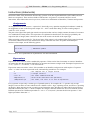
The fast inputs FX1 and FX2 can be connected to the A and B channels of a quadrature encoder. In this case EZRed traces the encoder position in a 32-bit register accessible by program. When the encoder makes a step in "+"
direction, the register increments by one; if the register was already containing the hexadecimal number
FFFFFFFF, it resets to 0 (overflow). Likewise, when the encoder makes a step in "-" direction the register
decrements; if it is already 0, it becomes FFFFFFFF (underflow).
The register is 32 bits wide, but the PLC program only uses numbers of 16 bits, so the register is split in low
(ENCODERL, the "L" stays for "low") and high part (ENCODERH, the "H" stays for "high"). If the positions
are limited to the range 0 to 65535 the high part can be completely ignored.
Encoder preset
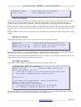
It is possible to do a zero or set of the encoder register (preset). Because the hardware register is 32 bits wide, but
it is accessed in two 16-bits operations, it is mandatory to write the low part first, and then the high part:
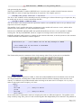
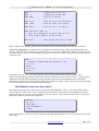
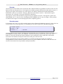
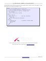
; encoder preset
encoderL = 200
encoderH = 0
; optional
As soon as the low part is written, the high part is automatically set to 1 (by hardware). This is not a problem if
ENCODERH is not used in the cycle; if instead it is, the next instruction sets it to the desired value. This
behavior is necessary because the encoder hardware works continuously, and it could detect a movement
between the first and the second preset instruction, leading to erroneous results.
The PLC program does not use negative numbers, so instead of zeroing the encoder (for example in
correspondence of a limit switch) it is better to preset it to a positive number, like 200 or 1000. This allow the
encoder to decrement a few steps without causing an underflow.
www.xonelectronics.it
Page 17/31