1
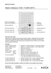
TC3XY Series
Access Controller
Hardware Manual
KEYKING GROUP
TC3XY Access Controller Installation Manual (PCB:V4.0)
Index
Chapter 1 - Introduction ......................................................................................................................................... 4
1.1
Keyking Overview .............................................................................................................................4
1.2
Models.............................................................................................................................................4
1.3
Numbering Sequence........................................................................................................................5
1.4
Software ..........................................................................................................................................5
Chapter 2 - Structure and Specifications............................................................................................................... 6
2.1
General Features..............................................................................................................................6
2.2
Wiegand Protocol .............................................................................................................................6
2.3
Multi Format .....................................................................................................................................6
2.4
Cardholder Database ........................................................................................................................6
2.5
Event Buffer .....................................................................................................................................6
2.6
Access Options ................................................................................................................................7
2.7
Time Zones ......................................................................................................................................7
2.8
Multi-Door Status Schedule ...............................................................................................................7
2.9
Hardware Components......................................................................................................................7
2.10 Self Monitoring .................................................................................................................................7
2.11 High Voltage Protection .....................................................................................................................7
2.12 Inputs & Outputs...............................................................................................................................7
2.13 Communication ................................................................................................................................8
2.14 Dimensions ......................................................................................................................................8
2.15 Miscellaneous Specifications .............................................................................................................8
Chapter 3 - Communication Protocols, Methods & Converters ......................................................................... 9
3.1
Introduction ......................................................................................................................................9
3.2
Option 1 - PC Serial Com Port (RS-232) to controller RS-232 port directly..............................................9
3.3
Option 2 - PC Serial Com Port (RS-232) via RS-232 to RS-485 converter ............................................10
3.4
Option 3 - TCP/IP to TCP/IP enabled controller..................................................................................11
3.5
Option 4 - TCP/IP to RS-485 Converter.............................................................................................12
3.6
RS-232 to RS-485 Converter ...........................................................................................................13
3.7
C2100 - TCP/IP to RS-485 Converter ...............................................................................................14
3.8
Controller Dipswitches.....................................................................................................................15
3.9
RS-485 Interface Notes ...................................................................................................................18
3.10 WAN/Internet Connection ................................................................................................................19
3.11 RS-485 Hub/Repeater.....................................................................................................................20
Chapter 4 – Wiring ................................................................................................................................................ 23
4.1
General Features............................................................................................................................23
Keyking Group Limited
33 Jabotinski St., Twin Tower 1, Ramat Gan, 52511,Israel
Tel: (972) 3-5753606/7 Fax: (972) 3-5753608 Website: www.key-king.com
Page 2
TC3XY Access Controller Installation Manual (PCB:V4.0)
4.2
Wiegand Interface Wiring.................................................................................................................23
4.3
RJ45 wiring for KEYKING Readers...................................................................................................24
4.4
RJ45 wiring for HID Readers............................................................................................................24
4.5
Connecting Keyking 6609E_M readers.......................................................................................24
4.5.1 Support Card Type:....................................................................................................................... 24
4.5.2 system Characteristics .................................................................................................................. 25
4.5.3 6609 surface: ............................................................................................................................... 26
4.5.4 6609 Wiring:................................................................................................................................ 26
4.5.5 Mode setting:............................................................................................................................... 27
Wiegand 26 Bits .................................................................................................................................... 27
Wiegand 34 Bits .................................................................................................................................... 27
4.6
RJ45 wiring for Long Range Readers (For Example 6688LE)..............................................................27
4.7
Lock Wiring ....................................................................................................................................28
4.8
RS-232/485/TCP Communication Wiring...........................................................................................29
4.9
Controller Wiring.............................................................................................................................30
4.10 Cable Specifications........................................................................................................................31
Chapter 5 – PCB Layouts & Connections ........................................................................................................... 32
5.1
General Features............................................................................................................................32
5.2
Model TC312..................................................................................................................................32
5.3
Model TC322..................................................................................................................................34
5.4
Model TC344..................................................................................................................................35
5.5
Model TC348..................................................................................................................................36
5.6
Model TC388..................................................................................................................................37
5.7
Model PSWC1230 ..........................................................................................................................38
Chapter 6 – Initial Setup....................................................................................................................................... 40
6.1
Controller Addresses.......................................................................................................................40
6.2
Reset the Controller ........................................................................................................................41
6.3
Before Power Up ............................................................................................................................41
6.4
Power Up.......................................................................................................................................41
Chapter 7 – Firmware Upgrades.......................................................................................................................... 42
7.1
Overview........................................................................................................................................42
Chapter 8 – Trouble Shooting............................................................................................................................... 43
Keyking Group Limited
33 Jabotinski St., Twin Tower 1, Ramat Gan, 52511,Israel
Tel: (972) 3-5753606/7 Fax: (972) 3-5753608 Website: www.key-king.com
Page 3
TC3XY Access Controller Installation Manual (PCB:V4.0)
Chapter 1 - Introduction
1.1
Keyking Overview
KEYKING GROUP is the world’s leading manufacturer and supplier of door entrance solutions, meeting tough
end-user demands for safety, security and user friendliness. The Group has some 500 employees and annual
sales of about EUR 3 billion. With more that 10 companies operating in 4 countries, KEYKING GROUP has a
strong global presence and holds more than 10 percent of the world market. The KEYKING GROUP web site
is www.keyking.net.
KEYKING is a KEYKING GROUP company and brand which is managed from Israel specializing in electronic
locking solutions. The KEYKING web site is www.keyking.net. KEYKING are now building on their reputation
as a provider of security electronic products by introducing a range of electronic security access control
products to compliment these locks.
1.2
Models
Keyking TC3XY series of access controllers comprise of 6 main models as listed below. These models have
RS-232 & RS-485 and TCP/IP communication built in enabled.
Model TC312MT
1 door, 2 readers, i.e. entry and exit readers, RS-232/RS-485
Model TC322MT
2 doors, 2 readers, i.e. entry readers with REX, RS-232/RS-485
Model TC344MT
4 doors, 4 readers, i.e. entry readers with REX, RS-232/RS-485
Model TC348MT
4 doors, 8 readers, i.e. entry and exit readers, RS-232/RS-485
Model TC388MT
8 doors, 8 readers, i.e. entry readers with REX, RS-232/RS-485
Model PSWC1230MT 16 floor lift controller with reader port RS-232/RS-485 (expandable to 128
floors)
Each of these controllers can be enabled for TCP/IP communications by the addition of a plug in TCP/IP
module. The TCP/IP enabled model has a suffix of T following the model number.
Model TC312NT
1 door, 2 readers, i.e. entry and exit readers, RS-232/RS-485/TCPIP
Model TC322NT
2 doors, 2 readers, i.e. entry readers with REX, RS-232/RS-485/TCPIP
Model TC344NT
4 doors, 4 readers, i.e. entry readers with REX, RS-232/RS-485/TCPIP
Model TC348NT
4 doors, 8 readers, i.e. entry and exit readers, RS-232/RS-485/TCPIP
Model TC348NT
8 doors, 8 readers, i.e. entry readers with REX, RS-232/RS-485/TCPIP
Model PSWC1230NT 16 floor lift controller with reader port RS-232/RS-485/TCPIP (expandable)
All Keyking Access controllers come standard in a Keyking branded mild steel black cabinet complete with 12V
2A power supply unit, fuse isolation block, key lock and 2 keys. Controllers are also available as PCB’s only.
Keyking Group Limited
33 Jabotinski St., Twin Tower 1, Ramat Gan, 52511,Israel
Tel: (972) 3-5753606/7 Fax: (972) 3-5753608 Website: www.key-king.com
Page 4
TC3XY Access Controller Installation Manual (PCB:V4.0)
1.3
Numbering Sequence
The KEYKING controller model numbers sequence is based on the following:
Model TC348NT, where:
3 = the controller series
4 = the number of doors
8 = the total number of reader ports on the controller
NT = TCP/IP plug in module is fitted
1.4
Software
KEYKING Security Management Sphinx 4.0 Software is available to work in association with the hardware.
The software has the following features:
Multi language
Multi Database (SQL or MS Access)
Client Server
Single User/Multi User
USB Hardware Key protected
Keyking Sphinx 4.0 Security Management Software is modular. The following modules are currently available:
Access Control, CCTV, Intrusion, Car Parking, Elevator Control, Visitors, Time&Attendance
The installation and operating instructions for the Sphinx 4.0 Integrated Security Software is covered in the
Sphinx 4.0 User Manual.
Keyking Group Limited
33 Jabotinski St., Twin Tower 1, Ramat Gan, 52511,Israel
Tel: (972) 3-5753606/7 Fax: (972) 3-5753608 Website: www.key-king.com
Page 5
TC3XY Access Controller Installation Manual (PCB:V4.0)
Chapter 2 - Structure and Specifications
2.1
General Features
Keyking TC3XY controllers are all fully intelligent and can be used in a standalone or networked configuration.
Programming is done via a PC however once programming has been completed the PC can be removed if
required and only connected when additional programming is required or the event buffer needs to be
uploaded to the PC.
Keyking TC3XY Series of controllers come standard with a RS-232 port for direct connection to a PC plus a
RS-485 port for connection to a RS-485 line. An optional TCP/IP plug on module is available for TCP/IP
communication. See the chapter on Communication Protocols and Methods. The Controller’s series support
both single directional and bidirectional doors.
Up to 127 controllers can be networked on a single RS-485 communication line giving a maximum of over 500
doors. The system supports up to 10 x RS485 individual communication lines giving a theoretical maximum of
over 5000 doors on a single system.
The controllers utilize Ethernet RJ-45 sockets for the connection of card readers and other Wiegand devices to
the controller. These plug in connectors offer easy changeover of PCB’s and allow the size of the larger
controllers, TC344, TC348 and TC388 to be reduced. All the controller PCB’s have the same mountings and
all fit in the same standard KEYKING black cabinet.
2.2
Wiegand Protocol
The KEYKING TC3XY Series controllers can support any Wiegand output device that gives an output of
between 24 and 72 bits.
2.3
Multi Format
Wiegand formats can be individually configured to allow for most common standard and proprietary card
formats. EM, MIFARE, all the HID formats plus Indala formats can be accepted. Also multiple formats are
available for every reader on the system at any one time, not just available to single readers or controllers as
in some systems. See the KEYKING Sphinx 4.0Software manual for more information.
2.4
Cardholder Database
All the TC3XY Series controllers’ support up to 30,000 cardholders and this is fixed. There is no memory
upgrade option available. Note that in some special cases where custom firmware is used and the firmware is
modified to suit particular requirements, this figure may be reduced.
2.5
Event Buffer
The TC312, TC322 and TC344 models store up to 15,000 events in off line mode.
The TC348 and the TC388 models store up to 7000 events in off line mode.
Keyking Group Limited
33 Jabotinski St., Twin Tower 1, Ramat Gan, 52511,Israel
Tel: (972) 3-5753606/7 Fax: (972) 3-5753608 Website: www.key-king.com
Page 6
TC3XY Access Controller Installation Manual (PCB:V4.0)
Note that in some special cases where custom firmware is used and the firmware is modified to suit particular
requirements, this figure may be reduced
2.6
Access Options
Supports multi programmable access methods: Card, Card + 4 digits PIN, Card Only mode (Max 1500 x 8 digit
PIN’s) Super 8 digits Master PIN, Multi-cards and Anti pass back.
2.7
Time Zones
Supports 15 Time Zones per door.
2.8
Multi-Door Status Schedule
Every door can be programmed to change its status at a specified date/time. There are several statuses of
doors that can be defined according to user requires such as: Normal (uses card to open the door), Always
Open, Always Closed and PIN required. Door Open Time can be programmed from 1 to 255 seconds.
2.9
Hardware Components
Memory 64K ROM, 512K SRAM
2.10
Self Monitoring
System self checks are supported
Data checksum protected
2.11
High Voltage Protection
All inputs and outputs are protected from high voltage.
5 years Lithium cell for maintaining memory and real time clock
Data is stored up to 90 days without power
2.12
Inputs & Outputs
Door Sensor Inputs:
Normally Closed (N.C.)
Auxiliary Inputs:
Normally Closed (N.C.) or Normally Open (N.O.)
Exit Button Inputs:
Normally Open (N.O.)
Model TC312
5 inputs and 3 outputs
Model TC322
8 inputs and 4 outputs
Model TC344
10 inputs and 6 outputs
Model TC348
10 inputs and 8 outputs
Model TC388
16 inputs and 8 outputs
Keyking Group Limited
33 Jabotinski St., Twin Tower 1, Ramat Gan, 52511,Israel
Tel: (972) 3-5753606/7 Fax: (972) 3-5753608 Website: www.key-king.com
Page 7
TC3XY Access Controller Installation Manual (PCB:V4.0)
2.13
Communication
RS-232/RS-485 Baud rate: 19200/9600/4800 1,1,n
TCPIP: 10/100
2.14
Dimensions
TC312 PCB:
165mm x 112mm x 25mm
TC322 PCB:
165mm x 112mm x 25mm
TC344 PCB:
170mm x 112mm x 25mm
TC348 PCB:
185mm x 112mm x 25mm
TC388 PCB:
185mm x 112mm x 25mm
Mild steel metal cabinet: 355mm high, 285 mm wide, 70mm deep
Weight: 2.4 Kg (in cabinet with power supply )
2.15
Miscellaneous Specifications
Power Input: 15VDC (±30%) or 16V AC (±20%) 50/60 Hz, working current <0.3A
Input: Dry input
Power Output: 12VDC, 1A max
Temperature: -20 ℃ ~70 ℃.
Humidity: 0~90%
Reader Communication: TTL level, 12V DC, 150mA, cable: 4 pair twisted with shield, 24AWG, max distance
150 meters, (500 feet).
Keyking Group Limited
33 Jabotinski St., Twin Tower 1, Ramat Gan, 52511,Israel
Tel: (972) 3-5753606/7 Fax: (972) 3-5753608 Website: www.key-king.com
Page 8
TC3XY Access Controller Installation Manual (PCB:V4.0)
Chapter 3 - Communication Protocols, Methods & Converters
3.1
Introduction
A standard Windows based PC using either Windows 2000 or Windows XP as the operating system can be
used to run the KEYKING Sphinx 4.0 Software. This software connects to the controller to allow controller
programming and the uploading of review events. The controllers will run in off line mode if no PC is available
although the events will be overwritten when the event buffer is full, oldest event overwritten first. There are 4
different methods of communication available to connect a PC running the KEYKING Sphinx 4.0 Software to
the KEYKING TC3XY Series of Access Controllers. Two of these use RS-232 serial data ports, the other 2
use TCP/IP. These 4 options are listed in detail below.
3.2
Option 1 - PC Serial Com Port (RS-232) to controller RS-232 port directly
The 1st option uses a RS-232 serial communication port and allows the PC to communicate
with a single panel only. This is often used for technician programming and can be used
permanently providing the PC is within 15 meters (50 feet) of the panel. A free
communication port is required.. Figure 3-1 shows the connection lead from a PC D9 serial
connector to a controller. Figure 3-2 below shows the pin connections for the connection lead
from the PC D9 serial connector to a controller.
PC Serial Port (DB9)
RS232
Connections
Figure 3-1
Controller
PIN2
PIN3
PIN5
RX
TX
GND
Figure 3-2
Figure 3-3 below shows the connection between the PC and controller as a schematic.
UNIT ID
INITAL
MODLE: DPU3002/S_NT/TC322
PCB:04.012.020
SW1
D1
XJ1
LED1
D2
XJ2
LED2
D3
XJ3
LED3
D3
XJ3
LED3
BATT1
TCP/IP DIP Switch
+
TB2
Figure 3-3
Keyking Group Limited
33 Jabotinski St., Twin Tower 1, Ramat Gan, 52511,Israel
Tel: (972) 3-5753606/7 Fax: (972) 3-5753608 Website: www.key-king.com
Page 9
TC3XY Access Controller Installation Manual (PCB:V4.0)
3.3
Option 2 - PC Serial Com Port (RS-232) via RS-232 to RS-485 converter
The 2nd option uses a RS-232 serial communication port and an external RS-232 to RS-485 adapter which
called IC232. This option is used where the PC is more than 15 meters from the controller or where more
than one controller is required. RS-232 serial data is used from the PC to the converter then RS-485 is used
from the converter to the controller(s). (Figure 3.6) The KEYKING model number for this converter is IC-232.
Using this method a maximum of 127 controllers can be connected to a single RS-232 serial port. The last
controller can be located at a maximum distance of 1200 meters (4000 feet) from the converter. As with
Option 1, a free communication port is required.. Figure 3-4 shows the RS-232 to RS-485 Protocol Converter
and figure 3-5 shows the pin connections for the converter. Figure 3-6 at the bottom of the page shows the
connection between the PC and controllers as a schematic.
Figure 3-5
Figure 3-4
UNIT IDINITAL
UNIT IDINITAL
MODLE: DPU3002/S_NT/TC322
PCB:04.012.020
SW1
XJ1
LED3
D3
LED3
XJ1
LED2
D3
XJ3
LED3
D3
XJ3
LED3
BATT1
XJ2
LED2
D3
XJ3
LED3
D3
XJ3
LED3
BATT1
TCP/IP DIP Switch
D1
LED2
D3
LED3
D3
XJ3
LED3
XJ1
XJ2
XJ3
XJ3
BATT1
TCP/IP DIP Switch
+
TB2
MODLE: DPU3002/S_NT/TC322
PCB:04.012.020
LED1
D2
XJ3
TCP/IP DIP Switch
+
TB2
XJ1
XJ2
BATT1
TCP/IP DIP Switch
+
UNIT IDINITAL
SW1
D1
LED1
D2
D2
XJ2
MODLE: DPU3002/S_NT/TC322
PCB:04.012.020
SW1
D1
LED1
D2
LED2
D3
UNIT IDINITAL
MODLE: DPU3002/S_NT/TC322
PCB:04.012.020
SW1
D1
LED1
+
TB2
TB2
Figure 3-6
Keyking Group Limited
33 Jabotinski St., Twin Tower 1, Ramat Gan, 52511,Israel
Tel: (972) 3-5753606/7 Fax: (972) 3-5753608 Website: www.key-king.com
Page
10
TC3XY Access Controller Installation Manual (PCB:V4.0)
3.4
Option 3 - TCP/IP to TCP/IP enabled controller
The 3rd communication option uses the plug in TCP/IP module to upgrade a
non-TCP/IP enabled controller to a TCP/IP enabled controller. The PC is
connected to the local network (LAN) hub/switch which in turn is connected
to the controller. This connection can be direct, ie off the same hub/switch or
indirect, through gateways, routers, WAN’s or the Internet. The KEYKING
model number for this module is NT (Network).
Figure 3-7
Figure 3-7 above shows the add on TCP/IP plug in module that enables a non-TCP/IP controller for TCP/IP
communications while figure 3-8 below shows a basic TCP/IP connection between a LAN based PC and a
controller on the same LAN. Note that the maximum distance for any TCP/IP Lan segment is 100m.
UNIT IDINITAL
UNIT IDINITAL
MODLE: DPU3002/S_NT/TC322
PCB:04.012.020
SW1
XJ1
LED3
LED3
BATT1
XJ3
LED3
BATT1
TCP/IP DIP Switch
XJ2
D3
XJ3
D3
LED3
XJ3
BATT1
TCP/IP DIP Switch
+
TB2
XJ1
D2
LED3
XJ3
BATT1
TCP/IP DIP Switch
+
D1
LED2
XJ3
D3
D3
LED3
MODLE: DPU3002/S_NT/TC322
PCB:04.012.020
LED1
XJ2
D3
XJ3
LED3
XJ1
D2
LED2
D3
XJ3
SW1
D1
LED1
XJ2
LED2
XJ3
D3
LED3
XJ1
D2
XJ2
D3
UNIT ID INITAL
MODLE: DPU3002/S_NT/TC322
PCB:04.012.020
SW1
D1
LED1
D2
LED2
UNIT IDINITAL
MODLE: DPU3002/S_NT/TC322
PCB:04.012.020
SW1
D1
LED1
TCP/IP DIP Switch
+
TB2
+
TB2
TB2
Figure 3-8
Keyking Group Limited
33 Jabotinski St., Twin Tower 1, Ramat Gan, 52511,Israel
Tel: (972) 3-5753606/7 Fax: (972) 3-5753608 Website: www.key-king.com
Page
11
TC3XY Access Controller Installation Manual (PCB:V4.0)
3.5
Option 4 - TCP/IP to RS-485 Converter
The 4th communication option uses a TCP/IP to RS-485 protocol with the C2100 converter.
The PC is connected to the local LAN as in option 3 however at the controller end a
TCP/IP to RS-485 converter is used. As with option 3 the controller can be located on the
same LAN as the PC or at a different location provided that there is a TCP/IP connection
between the PC and the converter. With this option a TCP/IP plug in module is not
required. If RS-485 is selected as the converter output, this option allows a PC to connect
to up to 127 controllers over a maximum distance of 1200 meters using a single converter
IP address. The KEYKING model number for this converter is C2100 (Protocol Converter
TCP/IP External). Figure 3-9 above shows the TCP/IP to RS-485 converter.
Figure 3-9
Figure 3-10 below shows a basic TCP/IP connection between a LAN based PC, a TCP/IP to RS-485 converter
and 3 controllers on a single RS-485 line.
UNIT ID
INITAL
MODLE: DPU3002/S_NT/TC322
PCB:04.012.020
SW1
D1
XJ1
LED1
D2
XJ2
LED2
D3
XJ3
LED3
D3
XJ3
LED3
BATT1
TCP/IP DIP Switch
+
TB2
UNIT ID
INITAL
MODLE: DPU3002/S_NT/TC322
PCB:04.012.020
SW1
D1
XJ1
LED1
D2
XJ2
LED2
D3
XJ3
LED3
D3
XJ3
LED3
BATT1
TCP/IP DIP Switch
+
TB2
UNIT ID
INITAL
MODLE: DPU3002/S_NT/TC322
PCB:04.012.020
SW1
D1
XJ1
LED1
D2
XJ2
LED2
D3
XJ3
LED3
D3
XJ3
LED3
BATT1
TCP/IP DIP Switch
+
TB2
Figure 3-10
Keyking Group Limited
33 Jabotinski St., Twin Tower 1, Ramat Gan, 52511,Israel
Tel: (972) 3-5753606/7 Fax: (972) 3-5753608 Website: www.key-king.com
Page
12
TC3XY Access Controller Installation Manual (PCB:V4.0)
3.6
RS-232 to RS-485 Converter
The RS-232 to RS-485 converter, (Figure 3-11) is used to convert RS-232 serial port data from a PC to RS485 data for use with the KEYKING controllers. It is used with Option 2, see earlier this chapter. The maximum
distance of the RS-485 line is 1.2 km, 4000 feet, from the converter to the last controller. The maximum
distance that the converter can be away from the PC serial port is 15 m, 50 feet. The KEYKING model number
for this converter is IC232.
Figure 3-11
Dip Switch Settings
A 4 way dip switch allows baud rate configuration and data format selection. Dip switches 1-3 are used to set
the baud rate, (Figure 3-12) and dip switch 4 is used to set the data format selection, (Figure 3-13). 9600 baud
is the default setting for the baud rate and “ON” is the default setting for the Data Format Switch.
Baud rate
DIP 1
DIP 2
DIP 3
(bps)
Baud rate
DIP 1
DIP 2
DIP 3
(bps)
300
OFF
OFF
OFF
4800
OFF
OFF
ON
600
ON
OFF
OFF
9600
ON
OFF
ON
1200
OFF
ON
OFF
19200
OFF
ON
ON
2400
ON
ON
OFF
38400
ON
ON
ON
Switch
State
Function description:
OFF
Standard 11 bits transmitting mode (8,1,1,n modes)
ON
Auto-checking data bits (default setting).
DIP 4
Keyking Group Limited
33 Jabotinski St., Twin Tower 1, Ramat Gan, 52511,Israel
Tel: (972) 3-5753606/7 Fax: (972) 3-5753608 Website: www.key-king.com
Figure 3-12
Figure 3-13
Page
13
TC3XY Access Controller Installation Manual (PCB:V4.0)
3.7 C2100 - TCP/IP to RS-485 Converter
The C2100 TCP/IP to RS-485 converters, (Figure 3-14) are used to convert TCP/IP data to RS-485
data for use with the TC3XY controllers. It is used with Option 4, see earlier this chapter. The
maximum distance of the RS-485 line is 1.2 km, 4000 feet. The maximum distance that the
converter can be away from the hub or switch is 100m. The model number for this converter is
C2100.
Figure 3-14
Dip Switch Settings
A 4 way dip switch allows the installer to configure the converter, (Figure 3-15)
When using the C2100 converter with TC3XY series and Sphinx 4.0 SW DIP 1,2 and 3 should be
OFF.
Switch
DIP 1
DIP 2
DIP 3
DIP 4
State
OFF
ON
OFF
ON
OFF
ON
OFF
ON
Function
Write Protect
Configurable
Normal Status
Reset the IP to the default (10.1.1.10)
Not Used
Not Used
Normal
Restart
Figure 3-15
Keyking Group Limited
33 Jabotinski St., Twin Tower 1, Ramat Gan, 52511,Israel
Tel: (972) 3-5753606/7 Fax: (972) 3-5753608 Website: www.key-king.com
Page
14
TC3XY Access Controller Installation Manual (PCB:V4.0)
3.8 Controller Dipswitches
S1(Switch #1):
When using RS-485 each controller must have its own ID selected by DIP Switches S1-S7. A “0”
address is invalid.
Dip Switch 1 is the 8 way Dip Switch at the top of the KEYKING controller, (Figures 3-16 and 3-17)
The 1st 7 switches of Dip Switch 1 are used for setting the RS-485 ID address using Binary. When
the switch is ON this means a 1, when it is OFF it means a 0. The 1st position is a 1, the 2nd a 2, the
3rd a 4, the 4th a 8, the 5th a 16, the 6th a 32 and the 7th a 64. So if all these 7 switches are on it
means an address of: 1 + 2+ 4+ 8+ 16+ 32+ 64 = 127. So the largest address is "111111" in Binary
Figure 3-16
which is 127 in decimal.
Switch 8 of DIP Wsitch 1 is used when resetting the controller and selects either a “COLD” or a
“HOT” reset. A “HOT” reset restarts the program, a “COLD” reset clears all memory and restarts
the program.
Dip Switch 2 is the 2 way dip switch located on the bottom half of the controller PCB and is used to
control the TCP/IP communication settings. (Figure 3.17)
Switches 1 to 7 = RS-485 address,
DIP
ID
DIP
Switch 1
(RS-485)
1
2
3
1
2
3
4
5
Sw 8 = Cold/Hot Reset
6
7
ON
ON
ON
ON
ON
ON
8
Status
Reset
ON
COLD
OFF
HOT
......
127
ON
ON
ON
ON
ON
Note: You must have a RS-485 address of at least 1
Figure 3-17
Keyking Group Limited
33 Jabotinski St., Twin Tower 1, Ramat Gan, 52511,Israel
Tel: (972) 3-5753606/7 Fax: (972) 3-5753608 Website: www.key-king.com
Page
15
TC3XY Access Controller Installation Manual (PCB:V4.0)
S1: Unit ID
S2: Function DIP Switch
DIP3, DIP8 = ON
S2 (Switch #2):
Switch
DIP 1
DIP 2
DIP 3
DIP 4
DIP 5
State
Function Description
OFF
Write Protect
ON
OFF
Configurable, Writeable
Normal
ON
Force the IP of converter
to the default IP 10.1.1.10
OFF
ON
OFF
ON
OFF
ON
ARM_JTAG
Normal
Normal
Detail
Parameters including Password, IP, Host IP cannot
be changed.
All parameters can be changed.
When the IP address of the TC348NT is not known,
switch DIP2 to on. The IP address will default to
10.0.0.10, and the password will default to “keyking”
Update Firmware only
Normally ON.
Normal
Keyking Group Limited
33 Jabotinski St., Twin Tower 1, Ramat Gan, 52511,Israel
Tel: (972) 3-5753606/7 Fax: (972) 3-5753608 Website: www.key-king.com
Page
16
TC3XY Access Controller Installation Manual (PCB:V4.0)
DIP 6
DIP 7
DIP 8
OFF
ON
OFF
ON
OFF
ON
Normal
Normal
Disable WDT
Enable WDT
Normal
S2: DIP Switch Normal Setting (Normal Operating Conditions):
Keyking Group Limited
33 Jabotinski St., Twin Tower 1, Ramat Gan, 52511,Israel
Tel: (972) 3-5753606/7 Fax: (972) 3-5753608 Website: www.key-king.com
Page
17
TC3XY Access Controller Installation Manual (PCB:V4.0)
3.9 RS-485 Interface Notes
If the RS-485 communication protocol is used in either Options 2 or 4 then the following applies.
In RS-485 mode the KEYKING TC3XY Series controllers use the half-duplex RS485 protocol which
can be up to 1200 meters (4000 feet) away from the converter. All controllers in the same RS485
line must be connected in a daisy chain or multi dropped configuration. (Figure 3-18) The RS-485
cable must not be connected at any points other than the controller(s) and the RS485 interface. A
good quality cable shield must be used and the shield must be connected to a strong earth ground.
Do not connect any RS485 wires to the GND of the controller.
If a shielded cable is used then the shield must be connected to ground or earth at a single point
only in order to avoid earth loops and data corruption. Where the RS-485 shielded cable connects
to a controller the shield between the IN cable and the OUT cable should be looped together but
insulated from ground. Note that if a RS-232 to RS-485 converter is being used to connect to a
desktop PC then the RS--485 line will be earthed via the computer.
The last controller on a RS-485 LAN must be terminated using a 120 ohm termination resistor.
(Figure 3-18). Note that the diagram shows an external termination resistor however a jumper
inserted on the pins located adjacent to the RS-232/485 terminal block on the controller inserts an
internal termination resistor in the circuit. Only one controller per RS-485 line needs to be
terminated.
120 ohm resistor
UNIT IDINITAL
UNIT IDINITAL
MODLE: DPU3002/S_NT/TC322
PCB:04.012.020
SW1
SW1
D1
LED1
XJ1
UNIT IDINITAL
LED2
XJ1
LED3
LED3
BATT1
LED3
XJ3
XJ3
BATT1
TCP/IP DIP Switch
+
TB2
XJ2
D3
LED3
D3
XJ3
TCP/IP DIP Switch
+
TB2
XJ1
D2
LED2
XJ3
BATT1
TCP/IP DIP Switch
+
D1
LED1
XJ2
D3
LED3
D3
XJ3
BATT1
XJ1
D2
LED2
XJ3
D3
LED3
MODLE: DPU3002/S_NT/TC322
PCB:04.012.020
SW1
D1
LED1
XJ2
D3
XJ3
UNIT IDINITAL
MODLE: DPU3002/S_NT/TC322
PCB:04.012.020
SW1
D1
D2
XJ2
D3
LED3
MODLE: DPU3002/S_NT/TC322
PCB:04.012.020
LED1
D2
LED2
+
TB2
TB2
Figure 3-18
Keyking Group Limited
33 Jabotinski St., Twin Tower 1, Ramat Gan, 52511,Israel
Tel: (972) 3-5753606/7 Fax: (972) 3-5753608 Website: www.key-king.com
Page
18
TC3XY Access Controller Installation Manual (PCB:V4.0)
3.10 WAN/Internet Connection
Using TCP/IP communication in either option 3 or 4 above allows a controller to be connected to a
PC running the KEYKING Sphinx 4.0 software over a WAN or the internet. Figure 3-19 below
shows a complex system where a number of TCP/IP enabled controllers plus a TCP/IP to RS-485
converter connected via TCP/IP to the PC. For this configuration to work the PC running the
software (or its internet address, ie the gateway) must have a static IP address. All controllers
require only a dynamic or DHCP allocated IP address. Specialist IT support will be required if
controllers are to be connected through gateways and routers as TCP/IP port 8000 needs to be
opened for incoming traffic and this port redirected to the PC running the KEYKING Sphinx 4.0
Software, refer section 3.11.
UNIT ID
INITAL
MODLE: DPU3002/S_NT/TC322
PCB:04.012.020
D1
XJ 1
D2
XJ 2
D3
XJ 3
D3
SW1
XJ 3
LED1
LED2
LED3
LED3
B ATT1
-
TCP/IP DIP Switch
+
UNIT ID
T B2
INITAL
MO DLE: DPU3002/S_NT/TC322
PCB:04. 012.020
D1
XJ1
D2
XJ2
D3
XJ3
D3
SW1
XJ3
LED1
LED2
LED3
LED3
T T1
BA
-
TCP/IP DIP Switch
+
T B2
UNIT ID
IN IT AL
U NIT ID
MO DLE: DPU3002/S_NT/TC322
PCB: 04.012.020
B ATT1
+
+
U NI T ID
XJ 3
XJ 3
XJ 2
XJ 3
XJ 3
LED2
LED3
L ED3
LED3
BATT1
BATT1
-
-
BATT1
XJ 1
LED1
L ED3
TCP/IP DIP Switch
TCP/IP DIP Switch
+
+
+
+
TB2
MODLE: D PU30 02 /S_NT/TC322
PCB:04.012.020
D1
D1
XJ 2
L ED2
TCP/IP DIP Switch
I NI TAL
SW1
XJ 1
L ED1
LED3
TB2
UNIT ID
MODLE: D PU 30 02 /S_N T/TC322
PCB:04.012.020
D2
XJ3
D3
XJ3
D3
D1
XJ2
LED3
TCP/IP DIP Switch
INI TAL
SW1
XJ1
LED2
D2
MOD LE: DPU3002/S_N T/TC322
PCB:04.01 2.020
LED1
BATT1
T B2
D3
INITAL
D2
D3
XJ 3
D3
D3
XJ 3
D3
D1
D2
XJ 2
TCP/IP DIP Switch
D3
B ATT1
-
TCP/IP DIP Switch
SW1
XJ 1
LED3
D1
LED3
-
UNIT ID
MOD LE: DPU3002/S_NT/TC322
PCB:0 4.01 2.020
LED3
XJ3
LED3
T B2
LED2
XJ3
LED2
LE D3
LED1
XJ2
LED1
LE D3
INITAL
XJ1
D2
D3
XJ3
D3
D3
XJ3
D3
D1
D2
XJ2
LE D2
UNIT ID
MODLE: DPU3002/S_NT/TC322
SW1
XJ1
LE D1
SW1
IN IT AL
PCB:04.012.020
SW1
TB2
Keyking Group Limited
33 Jabotinski St., Twin Tower 1, Ramat Gan, 52511,Israel
Tel: (972) 3-5753606/7 Fax: (972) 3-5753608 Website: www.key-king.com
TB2
Page
19
TC3XY Access Controller Installation Manual (PCB:V4.0)
Figure 3-19
3.11 RS-485 Hub/Repeater
The RS-485 Hub/Repeater has two modes of operation.
The 1st mode is that it is an RS-485 Repeater. In this mode it can be used to extend the distance of
a RS-485 line from the 1.2 km maximum (4000 ft) for another 1.2 km. Up to 2 x RS-485
Hub/Repeaters may be cascaded on the same RS-485 line.
The 2nd mode is as a splitter. RS-485 communications are designed to be in a multi drop or daisy
chain configuration. However, in some instances it may be impractical to run cables in a daisy chain
configuration and a star type configuration would be more convenient. When used in this mode it
can offer 4 x RS-485 lines.
The RS-485 Hub/Repeater uses an external 9v power supply and metal box the same size as the
RS-232 to RS-485 converter.
RS485HUB Features
• Velocity: 0-115200bps,Transmission Distance: 1200m (9600bps/h)。
• Temperature:-30℃- 70℃,Humidity: 5% -95%。
•
•
•
Improving RS485 communication distance and quality by increasing the signal.
Adjusted for difficult electromagnetic environment.
Every RS485 line has communication status led which blinks for normal
communication and turns red when there's a communication problem with the
controllers.
Pin Definition for RS232:
Keyking Group Limited
33 Jabotinski St., Twin Tower 1, Ramat Gan, 52511,Israel
Tel: (972) 3-5753606/7 Fax: (972) 3-5753608 Website: www.key-king.com
Page
20
TC3XY Access Controller Installation Manual (PCB:V4.0)
PC COM
1
2
6
4
3
7
8
Converter COM
5
5
9
4
9
2
3
8
7
1
6
Pin2(RxD) connect with Pin3(TxD)
Pin3(TxD) connect with Pin2(RxD)
Pin5(GND) connect with Pin5(GND)
Figure 3-20
Working modes
Mode 1: Splitting RS485 line to 4 RS485 lines.
SERVER
1200M
485+ L1
485Controller
Controller
15M
IC-232
RS232
RS485
HUB 485+
485-
RS485 1200M
Controller
Controller
Controller
1200M
L3
485+
485-
Controller
1200M
485+ L2
485RS232
.......
.......
.......
.......
Controller
Controller
Controller
1200M
485+ L4
485Controller
Controller
Controller
Figure 3-21
Keyking Group Limited
33 Jabotinski St., Twin Tower 1, Ramat Gan, 52511,Israel
Tel: (972) 3-5753606/7 Fax: (972) 3-5753608 Website: www.key-king.com
Page
21
TC3XY Access Controller Installation Manual (PCB:V4.0)
Mode 2: Converting RS232 to RS485 and splitting it to 4 RS485 lines.
SERVER
1200M
485+ L1
485Controller
Controller
RS232
15M
RS485
HUB 485+
485-
Controller
Controller
Controller
1200M
L3
485+
485-
Controller
1200M
485+ L2
485RS232
.......
.......
.......
.......
Controller
Controller
Controller
1200M
485+ L4
485Controller
Controller
Controller
Figure 3-22
Mode 3: Connecting the RS485HUB to IC232 converter in order to increase split the
RS485 line to 4 lines and to increase the communication range.
SERVER
1200M
485+ L1
485Controller
Controller
15M
IC-232
RS232
RS485
HUB 485+
485-
RS485
Controller
1200M
Controller
...
Controller
Controller
Controller
Controller
1200M
L3
485+
485-
Controller
1200M
485+ L2
485RS232
.......
.......
.......
.......
Controller
Controller
Controller
1200M
485+ L4
485Controller
Controller
Controller
Figure 3-23
Keyking Group Limited
33 Jabotinski St., Twin Tower 1, Ramat Gan, 52511,Israel
Tel: (972) 3-5753606/7 Fax: (972) 3-5753608 Website: www.key-king.com
Page
22
TC3XY Access Controller Installation Manual (PCB:V4.0)
Chapter 4 – Wiring
4.1 General Features
This chapter covers the system wiring required including the power supply connection,
communication connections, reader connections, lock connections, inputs/outputs and cable
specifications.
4.2 Wiegand Interface Wiring
In order to be able to use the same footprint size for all the TC3XY Series controllers the
connections between the Wiegand devices and the controller are by means of a RJ45 socket. The
RJ45 Pin Outs are below, see figure 4-1. Only 5 functions and 7 cable cores are used by the
controller. The blue/white wire, pin 5 is not used.
RJ45
Male
Female
8
Figure 4-1
Due to its low cost, installers nowadays use Cat 5 or above UTP cable for connecting of the card
readers to the controller. UTP cable is normally sufficient unless the cable is being run long
distances parallel to mains voltage cables or is being run through an area where there is excessive
electromagnetic interference in which case a shielded cable should be used. There are two wiring
standards for Cat 5 cables, a T-568A and a T-568B, but Keyking will use a different standard refer
figure 4-2 below. Depending upon the cable selected depends upon the PIN connections however
figures 4-3, 4-4 and 4-5 on the following pages list the most common KEYKING standard which is
the standard recommended for reader communication to the controller. Note that if a different wiring
configuration is used the two Wiegand data lines should be in the same pair to limit any interference.
Keyking Group Limited
33 Jabotinski St., Twin Tower 1, Ramat Gan, 52511,Israel
Tel: (972) 3-5753606/7 Fax: (972) 3-5753608 Website: www.key-king.com
Page
23
TC3XY Access Controller Installation Manual (PCB:V4.0)
Figure 4-2
4.3 RJ45 wiring for KEYKING Readers
RJ45 PIN
Number
1
2
3
4
5
6
7
8
RJ45 PIN
Definition
GND
Green LED
Not Used
Data 0
Data 1
12VDC
CAT5 Wire
Color 568B
Brown/White
Brown
Blue
Blue/White
Green
Green/White
Orange/White
Orange
4.4 RJ45 wiring for HID Readers
RJ45 PIN
Number
1
2
3
4
5
6
7
8
RJ45 PIN
Definition
GND
Green LED
Not Used
Data 0
Data 1
12VDC
CAT5 Wire
Color 568B
Brown/White
Brown
Blue
Blue/White
Green
Green/White
Orange/White
Orange
Reader Wire
Colour
Function
Black
GND
Orange
Not Used
Green
White
Green LED
Not Used
Data 0
Data 1
Red
5-14VDC
Figure 4-3
Reader Wire
Colour
Function
Black
GND
Orange
Not Used
Green
White
Green LED
Not Used
Data 0
Data 1
Red
5-14VDC
Figure 4-4
4.5 Connecting Keyking 6609E_M readers
4.5.1 Support Card Type:
1)
2)
3)
4)
5)
6)
7)
8)
E: EM; For example: EM4100, TK4100 series.
M: Mifare-; For example: Philips S50, S70 series smart cards.
RC: Mifare Sector; For example: Philips S50, S70 series smart cards.
H: HID Compatible; For example: 1326, 1386 and tags.
T: Temic, like E5557;
S: 15693; For example: Ti series cards.
B: TAP_B, For example: Chinese 2cd Identifitation;
C: TAP_C, Hongkong Metro;
Keyking Group Limited
33 Jabotinski St., Twin Tower 1, Ramat Gan, 52511,Israel
Tel: (972) 3-5753606/7 Fax: (972) 3-5753608 Website: www.key-king.com
Page
24
TC3XY Access Controller Installation Manual (PCB:V4.0)
4.5.2 system Characteristics
Technical Parameters:
zPower: 12 VDC ± 10%, 200mA
zDimensions: 86mm (H) x 86mm (W) x 18mm (D)
zWeight: 300 grams
zOperating Frequency:
125KHZ:
zE: EM;
zH: HID;
zT: Temic;
13.56MHZ:
zB: TAP_B;
zC: TAP_C;
zM: Mifare;
zRC: Mifare Sector;
zS: 15693;
zRead Range: 5 to 15 cm
zLED indicators: Dual LEDs, Blue&Green.
86m
86mm
Cover
Back
Figure 4-5
Keyking Group Limited
33 Jabotinski St., Twin Tower 1, Ramat Gan, 52511,Israel
Tel: (972) 3-5753606/7 Fax: (972) 3-5753608 Website: www.key-king.com
Page
25
TC3XY Access Controller Installation Manual (PCB:V4.0)
4.5.3 6609 surface:
Diagram
LED (Blue&Green)
Figure 4-6
LED:
z
z
Blue LED for power indication.
Green LED for card reading indication.
4.5.4 6609 Wiring:
Figure 4-7
Definition of wiring:
No.
Mark
Definition
1
+12V
Power Supply
2
D1
Data 1
Keyking Group Limited
33 Jabotinski St., Twin Tower 1, Ramat Gan, 52511,Israel
Tel: (972) 3-5753606/7 Fax: (972) 3-5753608 Website: www.key-king.com
Note
Page
26
TC3XY Access Controller Installation Manual (PCB:V4.0)
3
D0
Data 0
4
LED
LED control, when it was shorted with GND, then
LED will change the color.
5
GND
GND, Ground Wire
6
BUZ
Buzzer control, when it was shorted with GND,
then Buzzer will beep.
4.5.5 Mode setting:
Jumper Setting (JP1, valid for 6609E, 6609M only):
z None: the reader will output Wiegand 26 bits format.
z Short: the reader will output Wiegand 34 bits format.
Wiegand 26 Bits
Please keep nothing on the JP1, then the reader will output Wiegand 26 bits format.
Wiegand 34 Bits
Please keep a Jumper on the JP1 to short the 2 Pins, then the reader will output Wiegand 34 bits
format.
4.6 RJ45 wiring for Long Range Readers (For Example 6688LE)
RJ45 PIN
Number
1
2
3
4
5
6
7
8
RJ45 PIN
Definition
GND
Green LED
Not Used
Data 0
Data 1
12VDC
CAT5 Wire
Color 568B
Brown/White
Brown
Blue
Blue/White
Green
Green/White
Not Used
Not Used
Reader Wire
Colour
Function
Black
GND
Orange
Not Used
Green
White
Green LED
Not Used
Data 0
Data 1
Figure 4-8
z
z
When you need use a Long Rang Reader, for example 6688LE and HID5375, please use a different
power supply for the reader.
Please connect the GND of the Reader Power Supply to the GND of RJ45 (Pin1 and Pin2). Otherwise the
Software Sphinx4 will not get transactions when you show a card in the front of long range reader, even
you hear the “Di” sound.
Keyking Group Limited
33 Jabotinski St., Twin Tower 1, Ramat Gan, 52511,Israel
Tel: (972) 3-5753606/7 Fax: (972) 3-5753608 Website: www.key-king.com
Page
27
TC3XY Access Controller Installation Manual (PCB:V4.0)
4.7
Lock Wiring
All models of the KEYKING TC3XY Series controllers with the exception of models TC348 and TC388 have an
internal link between the +12v Lock socket at the bottom of the PCB board to the common terminal of the
output relays. To enable this, the jumpers directly below the relays must be connected. This saves the installer
wiring a common to each relay. See figures 5-1, 5-2 and 5-3.
The power supply as supplied with the KEYKING controllers is a 12V DC, 3A supply. However the original
transformer is only a 40VA which can supply 2 amps continuously. If more than 2 amps is required
continuously either an external power supply can be used or the transformer upgraded to a 60VA unit that can
supply 3 amps continuously.
Both PTO (power to open) and PTL (power to lock) locks can be used with the KEYKING controllers. PTO
locks are also called Fail Secure and PTL locks Fail Safe. Back EMF protection is required to be used. If the
lock does not have an internal back EMF protective diode then an external one must be fitted. This is placed
across the lock power supply cables and prevents any dangerous back EMF voltages from damaging the
controller electronics. Installers should take a note of equipment connected and the current draw so as to not
overload the transformer or power supply. Figure 4-9 shows the connections for a standard 12V Power to
Close lock while figure 4-10 shows the connections for a standard 12V Power to Open lock.
Keyking Group Limited
33 Jabotinski St., Twin Tower 1, Ramat Gan, 52511,Israel
Tel: (972) 3-5753606/7 Fax: (972) 3-5753608 Website: www.key-king.com
Page
28
TC3XY Access Controller Installation Manual (PCB:V4.0)
Figure
4-9
Figure
4-10
4.8
RS-232/485/TCP Communication Wiring
All models support RS-232/RS-485 communication protocols plus TCP/IP when the TCP/IP module is inserted.
Note that the controllers can only support a single communication interface at any one time. Refer to Chapter
3 for more information on the communication wiring and connections.
Keyking Group Limited
33 Jabotinski St., Twin Tower 1, Ramat Gan, 52511,Israel
Tel: (972) 3-5753606/7 Fax: (972) 3-5753608 Website: www.key-king.com
Page
29
TC3XY Access Controller Installation Manual (PCB:V4.0)
4.9
Controller Wiring
A detailed wiring table appears on the next page listing the cable specifications for wiring connected to the
KEYKING TC3XY Series Controllers. Below however as figure 4-8 is a schematic showing the major cable
types used in access control systems and their uses. Connected to a controller there are normally 5 cables as
follows:
Cable 1 – The card reader cable. This can be either 6 core, 3 or 4 pair UTP or twisted shielded depending
upon distance and electromagnetic interference.
Cable 2 – The input cable. This can be an 8, 10 or 12 core cable, 0.2 mm2 or 0.5 mm2 connecting the various
inputs with the controller. These inputs could include the REX, door contact, auxiliary input, bond or tongue
sense inputs or a break glass monitoring input.
Cable 3 – This is the power cable that supplies the lock. The lock power must be kept in a separate cable from
the input cable as spikes created by electromagnetic locks can be induced into input cables if these are run in
the same cable. This cable is normally run to the emergency break glass unit then to the lock.
Cable 4 – The cable connecting the controller to another controller, converter or TCP/IP switch/hub.
Cable 5 – The 230V power supply cable to the controller fuse block.
UNIT ID
INITAL
D1
DIP SWITCH 1
XJ1
LED1
D2
XJ2
LED2
D3
XJ3
LED3
D3
XJ3
LED3
Lock
Output
+12v DC
Common
Rail
-
DIP SWITCH 2
BATT1
+
12
+ +12
GND
5V V-LOCK
VDC
TB2
Figure 4-11
Keyking Group Limited
33 Jabotinski St., Twin Tower 1, Ramat Gan, 52511,Israel
Tel: (972) 3-5753606/7 Fax: (972) 3-5753608 Website: www.key-king.com
Page
30
TC3XY Access Controller Installation Manual (PCB:V4.0)
4.10
Cable Specifications
The table below lists the recommended cables for use with the KEYKING TC3XY Series Controllers
Use
Wiring Location
Cable Specification
Cable 1
Reader Cable
From reader to controller
4 pair shielded twisted pair .24AWG (0.206mm) is
recommended (Belden 9841) however parallel core
security cable or Cat 5 UTP will work adequately in
areas of low electromagnetic interference.
Maximum distance 150m (500 feet)
Cable 2
Assorted Inputs
Door sensor, REX, break
glass monitoring, bond
sense, tongue sense,
auxiliary input
6, 8, 10 or 12 core 0.2 mm2 or 0.5 mm2 parallel
core security cable or standard Cat 5 UTP. Does
not normally need to be shielded unless in an area
of exceptionally high electromagnetic interference
Cable 3
Lock Power Cable
From controller and power
supply to locks via break
glass (if fitted)
This cable depends upon distance and lock current
draw. For small runs (up to 10-15m) a twin
0.75mm2 cable is normally sufficient. For longer
runs a twin 1mm2, .a twin 1.5mm2 or even a twin
2.5mm2 cable could be required, not shielded.
Cable 4a
RS-485 Cable
From converters to
controllers and from
controllers to controllers
4 pair shielded twisted pair .24AWG (0.206mm) is
recommended.(Belden 9841) The maximum range
is 1200m (4000 ft) Cat 5 UTP will work adequately
in areas of low electromagnetic interference
however a shielded cable is recommended.
Cable 4b
TCP/IP Cable
From converters/controllers
to a TCP/IP hub/switch
Cat 5 or above UTP. Maximum distance 100m
Cable 5
230v Power Supply
Cable
From a switched 230 volt
power supply source to the
controllers fuse block
A single twin and earth 1.5mm2 or similar
depending upon local regulations
Controller Earth
From the Ground terminal of A single core 1mm2 or similar
the controller or power
supply to a valid earth
Figure 4-12
Keyking Group Limited
33 Jabotinski St., Twin Tower 1, Ramat Gan, 52511,Israel
Tel: (972) 3-5753606/7 Fax: (972) 3-5753608 Website: www.key-king.com
Page
31
TC3XY Access Controller Installation Manual (PCB:V4.0)
Chapter 5 – PCB Layouts & Connections
5.1
General Features
There are 5 basic models of the KEYKING TC3XY Series Controllers, Model TC312, a 1 door, 2 reader
controller, Model TC322, a 2 door 2 reader controller, Model TC344, a 4 door 4 reader controller, Model TC348,
a 4 door 8 reader controller and Model TC388, a 8 door 8 reader controller. All models are fully intelligent in off
line mode. The PCB layout for each of these models appears below and on the following pages. Although the
4 and 8 door PCB’s are slightly larger than the 1 and 2 door PCB’s, the mounting holes are all identical so the
same standard KEYKING TC3XY Series cabinet fits all controller PCB’s without modification. All PCB’s use
either the red snap on connectors or RJ-45 sockets for easy replacement of PCB’s.
5.2
Model TC312
The KEYKING Model TC312 is a single door controller that can be used with 2 readers, an IN and an OUT
reader to give bi-directional access control. The TC312 has 5 inputs and 3 outputs. The TC312 PCB layout
appears below (Figure 5-1)
Keyking Group Limited
33 Jabotinski St., Twin Tower 1, Ramat Gan, 52511,Israel
Tel: (972) 3-5753606/7 Fax: (972) 3-5753608 Website: www.key-king.com
Page
32
TC3XY Access Controller Installation Manual (PCB:V4.0)
INITAL
UNIT ID
1
2
3
4
5
6
7
1 Door Controller
8
SW1
D1
D2
Entry Reader 1
Lock Output 1
XJ1
XJ2
Aux Output 1
D3
Serial Number
XJ3
Aux Output 2
LED1
CPLD
LED2
LED3
Exit Reader 1
ARM
Mac Address
DIP
Status
DIP1
DIP2
DIP3
OFF
ON
IP Configurable
Write Protect
Normal
JTAG
Force IP to 10.1.1.10
Normal
S2 DIP Switch
1
2
3
4
5
6
DIP4
TCP/IP
Exit Reader
DIP5
DIP6
DIP7
CPLD-Fire
LMI-Fire
Enable WDT
BATT1
-
DIP8
Reset
8
S2
CPLD-Fire
LMI-Fire
LMI-Fire
CPLD-Fire
Normal (Disable WDT)
7
But1
+
485+
485RX
TX
GND
Sen1
Exit Button 1
Door Sensor 1
GND
JP10
SUB1
SUB2
GND
SUB3
Aux Input 1
Aux Input 2
Aux Input 3
GND
+12VDC
+12VDC
GND
Figure 5-1
Keyking Group Limited
33 Jabotinski St., Twin Tower 1, Ramat Gan, 52511,Israel
Tel: (972) 3-5753606/7 Fax: (972) 3-5753608 Website: www.key-king.com
Page
33
TC3XY Access Controller Installation Manual (PCB:V4.0)
5.3
Model TC322
The KEYKING Model TC322 is a two door controller that can be used with 2 x IN readers. REX buttons are
used for exit. The TC322 has 8 inputs and 4 outputs. The TC322 PCB layout appears below (Figure 5-2)
INITAL
UNIT ID
2 Doors Controller
1
2
3
4
5
6
7
8
D1
SW1
Serial Number
D2
CPLD
Reader 1
XJ1
Lock Output 1
LED1
XJ2
Lock Output 2
D3
XJ3
D4
LED2
XJ3
Aux Output 1
LED3
Reader 2
Aux Output 2
ARM
Mac Address
DIP
Status
DIP1
DIP2
DIP3
OFF
Write Protect
Normal
JTAG
ON
IP Configurable
Force IP to 10.1.1.10
Normal
S2 DIP Switch
1
2
3
4
5
6
7
Reset
8
DIP4
DIP5
DIP6
DIP7
TCP/IP
CPLD-Fire
LMI-Fire
Enable WDT
BATT1
LMI-Fire
CPLD-Fire
Normal (Disable WDT)
-
DIP8
CPLD-Fire
LMI-Fire
But1
+
485+
485RX
TX
GND
Sen1
Exit Button 1
Door Sensor 1
GND
But2
Sen2
Exit Button 2
Door Sensor 2
GND
JP10
SUB1
SUB2
GND
SUB3
SUB4
GND
Aux Input 1
Aux Input 2
Aux Input 3
Aux Input 4
GND
+12VDC
+12VDC
GND
Figure 5-2
Keyking Group Limited
33 Jabotinski St., Twin Tower 1, Ramat Gan, 52511,Israel
Tel: (972) 3-5753606/7 Fax: (972) 3-5753608 Website: www.key-king.com
Page
34
TC3XY Access Controller Installation Manual (PCB:V4.0)
5.4
Model TC344
The KEYKING Model TC344 is a four door controller that can be used with 4 x IN readers. REX buttons are
used for exit. The TC344 has 10 inputs and 6 outputs. The TC344 PCB layout appears below (Figure 5-3)
INITAL
UNIT ID
1
2
3
4
5
6
7
8
4 Doors Controller
D1
XJ1
D2
XJ1
D3
XJ1
D4
XJ1
D5
XJ1
D6
SW1
XJ1
Lock Output 1
LED1
Reader 1
Serial Number
LED2
CPLD
Reader 2
Lock Output 2
LED3
Lock Output 3
LED4
Reader 3
Lock Output 4
LED5
Reader 4
Aux Output 1
LED6
ARM
Aux Output 2
Mac Address
DIP
Status
DIP1
DIP2
DIP3
TCP/IP
OFF
ON
IP Configurable
Write Protect
Normal
JTAG
Force IP to 10.1.1.10
Normal
S2 DIP Switch
DIP4
DIP5
DIP6
DIP7
DIP8
1
2
3
4
5
6
7
LMI-Fire
CPLD-Fire
Normal (Disable WDT)
Reset
8
S2
CPLD-Fire
LMI-Fire
CPLD-Fire
LMI-Fire
Enable WDT
-
5
8
4
But1
485+
BATT1
Sen1
GND
But2
+
RX
TX
GND
Exit Button 1
Door Sensor 1
Sen2
Exit Button 2
Door Sensor 2
GND
JP10
But3
Sen3
Exit Button 3
Door Sensor 3
GND
But4
Sen4
Exit Button 4
Door Sensor 4
GND
SUB1
SUB2
GND
Aux Input 1
Aux Input 2
GND
+12VDC
+12VDC
GND
Figure 5-3
Keyking Group Limited
33 Jabotinski St., Twin Tower 1, Ramat Gan, 52511,Israel
Tel: (972) 3-5753606/7 Fax: (972) 3-5753608 Website: www.key-king.com
Page
35
TC3XY Access Controller Installation Manual (PCB:V4.0)
5.5
Model TC348
The KEYKING Model TC348 is a four door controller that can be used with 4 x IN readers and 4 x OUT
readers. No REX buttons are required. The TC348 has 10 inputs and 8 outputs. The TC348 PCB layout
appears below (Figure 5-4)
INITAL
UNIT ID
1
2
3
4
5
6
7
4 Doors Controller
8 Readers
8
SW1
D1
XJ1
D2
XJ1
D3
XJ1
D4
XJ1
D5
XJ1
D6
Lock Output 1
Entry Reader 1
Exit Reader 1
XJ1
LED1
Entry Reader 2
Exit Reader 2
CPLD
Lock Output 2
LED2
Entry Reader 3
Exit Reader 3
Lock Output 3
LED3
Entry Reader 4
Exit Reader 4
Lock Output 4
LED4
Serial Number
Lock Output 5
LED5
Lock Output 6
D7
ARM
XJ1
D8
LED6
XJ1
LED7
TCP/IP
Lock Output 7
Mac Address
LED8
S2 DIP Switch
DIP
DIP1
DIP2
DIP3
OFF
ON
IP Configurable
Write Protect
Normal
JTAG
Lock Output 8
S2 DIP Switch
Force IP to 10.1.1.10
Normal
DIP4
DIP5
DIP6
DIP7
DIP8
But1
1
2
3
4
5
6
7
8
LMI-Fire
CPLD-Fire
Normal (Disable WDT)
Sen1
S2
CPLD-Fire
LMI-Fire
Exit Button 1
Door Sensor 1
GND
CPLD-Fire
LMI-Fire
Enable WDT
But2
Sen2
JP10
Exit Button 2
Door Sensor 2
GND
BATT1
485+
485RX
TX
GND
Status
But3
Sen3
+
Reset Button
Exit Button 3
Door Sensor 3
GND
But4
Sen4
Exit Button 4
Door Sensor 4
GND
SUB1
SUB2
GND
SUB3
SUB4
GND
Aux Input 1
Aux Input 2
Aux Input 3
Aux Input 4
GND
+12VDC
+12VDC
GND
Figure 5-4
Keyking Group Limited
33 Jabotinski St., Twin Tower 1, Ramat Gan, 52511,Israel
Tel: (972) 3-5753606/7 Fax: (972) 3-5753608 Website: www.key-king.com
Page
36
TC3XY Access Controller Installation Manual (PCB:V4.0)
5.6
Model TC388
The KEYKING Model TC388 is a eight door controller that can be used with 8 x IN readers. The
TC388 has 16 inputs and 8 outputs. The TC388 PCB layout appears below (Figure 5-5).
INITAL
UNIT ID
1
2
3
4
5
6
7
8 Doors Controller
8
SW1
Reader 1
Reader 2
D1
D2
XJ1
D3
XJ1
D4
XJ1
D5
XJ1
D6
Lock Output 1
XJ1
XJ1
LED1
Reader 3
Reader 4
CPLD
Lock Output 2
LED2
Reader 5
Reader 6
Lock Output 3
LED3
Reader 7
Reader 8
Lock Output 4
LED4
Serial Number
Lock Output 5
LED5
Lock Output 6
D7
ARM
XJ1
D8
LED6
XJ1
LED7
TCP/IP
Lock Output 7
Mac Address
LED8
S2 DIP Switch
DIP
Status
DIP1
DIP2
DIP3
ON
IP Configurable
Write Protect
Normal
JTAG
Force IP to 10.1.1.10
Normal
Lock Output 8
S2 DIP Switch
But1
DIP4
DIP8
2
3
4
6
5
7
8
S2
CPLD-Fire
LMI-Fire
LMI-Fire
CPLD-Fire
Normal (Disable WDT)
Sen1
D
N
G
DIP5
DIP6
DIP7
1
CPLD-Fire
LMI-Fire
Enable WDT
But2
-
Sen2
D
N
G
JP10
BATT1
485+
485RX
TX
GND
OFF
+
D
N
G
Sen3
Reset Button
RS-485 EOL Terminator
But3
But4
D
N
G
Sen4
Exit Button 1
Door Sensor 1
Exit Button 2
Door Sensor 2
Exit Button 3
Door Sensor 3
Exit Button 4
Door Sensor 4
Sen5
But5
D
N
G
Sen6
But6
D
N
G
Sen7
But7
D
N
G
Sen8
But8
Exit Button 5
Door Sensor 5
Exit Button 6
Door Sensor 6
Exit Button 7
Door Sensor 7
D
N
G
Exit Button 8
Door Sensor 8
GND
+12VDC
+12VDC
GND
Figure 5-5
Keyking Group Limited
33 Jabotinski St., Twin Tower 1, Ramat Gan, 52511,Israel
Tel: (972) 3-5753606/7 Fax: (972) 3-5753608 Website: www.key-king.com
Page
37
TC3XY Access Controller Installation Manual (PCB:V4.0)
5.7
Model PSWC1230
The KEYKING Model PSWC1230 is a 12V, 3A power supply unit that comes standard with all KEYKING
TC3XY Series controllers and power supplies. (Figure 5-6) It can accept either a 12-17V AC input or a 18-22V
DC input. It provides 3 x 12v DC general purpose outputs, 1 x 5 amp relay output, a push button input and a
battery charging output. Two LED’s provide indication of AC Power (Red) and battery charging (Green).
The built in relay is suitable for a simple access system. The lock can be connected to the unit (Figure 5-6)
The +12V rail is internally connected to the relay common terminal. A normally open push button can be
connected which, when pressed will operate the relay for the time set by the adjustment potentiometer. The
time for the relay output can be adjusted to between 1 – 30 seconds.
Note that the KEYKING 12v PSU PCB is rated at 3 amps. However the transformer as shipped in the
KEYKING standard cabinet is only rated at 40VA and will therefore supply only 2 amps at 16v AC. That is why
the power supplies themselves are only continuously rated at 2 amps. If the full 3 amps is required from the
power supply then the transformer needs to upgraded to a 60 VA transformer supplying 16-17 V AC.
Relay Time Adjustment 1-30 seconds
Keyking Group Limited
33 Jabotinski St., Twin Tower 1, Ramat Gan, 52511,Israel
Tel: (972) 3-5753606/7 Fax: (972) 3-5753608 Website: www.key-king.com
Page
38
TC3XY Access Controller Installation Manual (PCB:V4.0)
Terminals from the left hand side are as follows: Figure 5-6
14V AC in
AC Input for 14-17V AC
Vin & Gnd
DC Voltage in, between 18-22v DC
+12v & Gnd
12V DC output
NO
Normally open relay contact, ie no voltage when relay de-energised
NC
Normally closed relay contact, ie 12V DC when relay de-energised
Gnd & Push
Input for push button. When shorted the relay energises
Batt
12V DC for back up battery
Keyking Group Limited
33 Jabotinski St., Twin Tower 1, Ramat Gan, 52511,Israel
Tel: (972) 3-5753606/7 Fax: (972) 3-5753608 Website: www.key-king.com
Page
39
TC3XY Access Controller Installation Manual (PCB:V4.0)
220-230V AC
Transformer
40VA
18VDC
GND
+12V
GND
+12V
GND
+12V
NO
NC
14-17V AC
Power Supply with Charger
Model: 7PSU
Output: 12V DC, 3A
Lock
Battery
12V, 7AH
Chapter 6 – Initial Setup
6.1
Figure 5-7
Controller Addresses
If the controller is being connected directly to a PC using RS-232, then no hardware configuration is required.
If the controller is being connected to a RS-485 line which is in turn connected to a RS232/485 converter then
the dip switches on the controller PCB at Dip Switch 1 must be configured. No configuration is required at the
converter. See Chapter 3. Note that address 0 for the controller is not a valid address. Duplicate addresses are
not allowed.
If the controller is being connected to a RS-485 line which is in turn connected to a TCP/IP converter then the
converter dip switches must be configured as well as the controller address at Dip Switch 1. See Chapter 3.
Note that address 0 for the controller is not a valid address. Duplicate addresses are not allowed.
If the controller is being connected directly to an Ethernet hub using the optional plug on TCP/IP module then
Keyking Group Limited
33 Jabotinski St., Twin Tower 1, Ramat Gan, 52511,Israel
Tel: (972) 3-5753606/7 Fax: (972) 3-5753608 Website: www.key-king.com
Page
40
TC3XY Access Controller Installation Manual (PCB:V4.0)
Dip Switch 2 on the controller must be configured, see Chapter 3.
6.2
Reset the Controller
Before installation any data in the RAM should be cleared. Set switch 8 on Dip Switch 1 to on, apply power,
press the reset button, wait 5 seconds, de-power, return switch 8 to off. Note that this does a COLD reset
which clears all data from memory. This data cannot be recovered.
6.3
Before Power Up
Confirm that the controller is earthed to the cabinet metalwork via a valid ground terminal on the PCB.
6.4
Power Up
Power up and check the DC voltage. Check the yellow power LED is lit. Check that the data LED’s are flashing.
For RS-232/485 communication the LED’s are adjacent to the RS-232/485 terminal block. For TCP/IP
communication the data LED’s are at the bottom of the PCB board. Note that these LED’s will only flash if
there is a valid data connection. For TCP/IP plug the Ethernet cable into the RJ-45 Ethernet port and make
sure that the optional TCP/IP module has been fitted. For RS-485 operation the PC Communication Port must
be configured from within the software before these lights will flash, see the KEYKING Sphinx 4.0 Software
Manual. For TCP/IP communication the PC must be on a TCP/IP network.
Keyking Group Limited
33 Jabotinski St., Twin Tower 1, Ramat Gan, 52511,Israel
Tel: (972) 3-5753606/7 Fax: (972) 3-5753608 Website: www.key-king.com
Page
41
TC3XY Access Controller Installation Manual (PCB:V4.0)
Chapter 7 – Firmware Upgrades
7.1
Overview
The KEYKING TC3XY Series access controllers use an 8 bit processor which is soldered onto the PCB. From
time to time to be able to receive new program features the firmware will need to be upgraded. This is done by
flashing or upgrading the firmware program within the processor. This is not a procedure that the user can
undertake and must be carried out by Keyking staff or authorized and trained engineers. Note that to be able
to use any new features both the firmware and software must be upgraded.
The firmware upgrade procedure is covered in detail in the Firmware Upgrade Manual which is available from
the Keyking Technical Support centers.
Keyking Group Limited
33 Jabotinski St., Twin Tower 1, Ramat Gan, 52511,Israel
Tel: (972) 3-5753606/7 Fax: (972) 3-5753608 Website: www.key-king.com
Page
42
TC3XY Access Controller Installation Manual (PCB:V4.0)
Chapter 8 – Trouble Shooting
Symptom
Possible Cause
Remedy
Yellow power LED
dead
No power or low power
Check the input voltage at the terminals on the bottom
of the PCB. It should be between 12V and 14VDC.
LED on reader dead
No power or low power
Check voltage at reader, it should be approximately 12v
DC between red and black. Check that the total current
draw from the controller is within limits.
There is a magnetic field near the
reader
Remove the item which produces the magnetic field.
Reader range is too
short.
Cannot open the
door when flashing
the cards. (Check
review event on PC
first)
With power on, the
reader goes
“BEEP” but the
controller cannot
process the
information.
The controller
cannot
communicate with
the converter.
Converter cannot
communicate with
PC.
Use the shielded cable.
The reader cable is not shielded.
Confirm there is at least 100mm between the reader
cable and any high voltage cables.
The reader has been mounted on a
metallic surface.
Remount the reader on a non metallic surface
The card is invalid for the door.
Use software to enable the card for the door
Time zone of the card is invalid.
Use software to set the user time zone to valid
Communication problem between
reader and the controller.
Check to see if the problem is caused by
electromagnetic interference If so increase the distance
between the reader cable and the interference or use
shielded cable
Lock problem
Check if the lock is working correctly
Wrong connection between
controller and readers.
Check the connection is correct.
Wiegand format is not correct.
Please check your reader and card formats. As a test
place all bits as 1 in the Wiegand Format Setup screen
in the software for that particular bit format.
Losing data from the controller.
Download the data again from the PC.
Converter power is off.
Supply power.
The baud rate setting is incorrect.
Set the baud rate the same as the software
The RS-485 wires are reversed
Use the correct connections
The COM port setting is incorrect.
Correct the Com Port setting. Note use Windows
Device Manager to find the correct comm. port.
The RS-232 connections are
reversed
Use the correct connections.
Keyking Group Limited
33 Jabotinski St., Twin Tower 1, Ramat Gan, 52511,Israel
Tel: (972) 3-5753606/7 Fax: (972) 3-5753608 Website: www.key-king.com
Page
43
TC3XY Access Controller Installation Manual (PCB:V4.0)
The power supply of the converter is
not sufficient.
The 9v PSU must be able to supply at least 300mA. If
you use a USB cable as a PSU, please use a 2nd USB
socket for the PSU or use a 9v, 300mA PSU.
Duplicate addresses
Make sure controllers have unique addresses
The data in the RAM of the
controller is corrupted.
Download the configuration again by using the
software.
RS485+ and RS485- reversed
Use the correct connections
The lock cannot be
locked.
No power or low power for the lock.
Check the power supply for lock.
The card number is
different to what is
expected
The reader output is set to 26 when
34 is required or the other way
around
Some of the
controllers on the
RS-485 LAN
cannot
communicate.
Check that the output relay operates
Reset reader output
Figure 8-1
Keyking Group Limited
33 Jabotinski St., Twin Tower 1, Ramat Gan, 52511,Israel
Tel: (972) 3-5753606/7 Fax: (972) 3-5753608 Website: www.key-king.com
Page
44