1
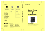
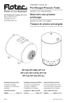
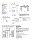
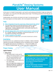
Menu '/ \ '1:, ADJUSTABLE SINGLE-STAGE INJECTORS MODELS: 202B, 202BP, 202BT, 203B, 203BP, 203BT, 204B, 204BP, 204BT, 206B, 206BP, 206BT MODEL #'S MAY ALSO INCLUDE S, E, C AND/OR -2. 24-33 I 'II 1 '00-" fr ~~:--I"§ u-'~" 100-24PS 24-25 24-24P 24-24S 24-23 24-34 25-29 --==> -0 24-36 ;::: ~: : 24-40 125-29 24-39 124-37 1 24-lIMP 24-23 24-24P 24-24S 24-25 24·32 24-32PS 24-32S 24-32ST 24-32T 24·33 24-34 24-35 24-36 24-37 24-38 1-119 Rev. A0500 1 3. J U ~ ------m. -0 §-- ~ DESCRIPTION FOOT STRAINER CHECK VALVE SPRING CHECK VALVE BALL (TEFLON) CHECK VALVE BALL (STAINLESS) CHECK VALVE DoRING METERING KNOB ASSY. METERING KNOB ASSY. (BPINJECTORS METERING KNOB ASSY. METERING KNOB ASSY. METERING KNOB ASSY. SCREW #8-32 X 7/8 LG. (4·REQD.) CHECK VALVE CORE (SPECIFY MODEL NO.) BY-PASS SCREW BY-PASS SCREW RETAINER BY-PASS SCREW BY-PASS SCREW RETAINER 24-47 24-48 24-49 25-29 26-17 61-107-2 100-12 100-15 100-15K 100-24 100-24PS " - METERING TIP (ASREQD.) See Fig. I for location of water bypass screw and fine metering adjustment screw. Tum on water supply valve. The injector may draw moment8rlly as the system is filling but normally will stop as the system builds up to full pressure. To actuate injector, tum the bypass screw clockwise until product begins to be drawn from the container. After the fluid reaches the injector, the feed rate may be adjusted to the desired rate by turning the bypass screw. The maximum injection rates are shown in Table 2. For low injection rates, it is advisable to set the'bypass screw for more injection than required; then tum the' fine metering screw clockwise to reduce injection to the desired rate. Table I shows the operation range ofthe injector. If the injector will not draw with the bypass screw full in, then the water flow is below the range ofthe injector. Ifthe injector d~ws with the screw full out but pressure loss is excessive, then flow is above the range of the injector. Table 3 shows tire injection rates for models 202 BT, 203 BT, 204 BT, and 206 BT using metering tips at various viscosities. Table" shows the appropriate pipe size used for each injector. ... TABLEt .~ Water Pressure (psi) 100-12 I :l'l-4U ADjUSTMENT SCREW Op«at'ing Range - Gallons Per Minute 61-107-2 PART NO FINE METERING ~ OPERAnON 24-1H& ~ 24-39 .. FIGURE I Warning: Use care when handling hazardous chemicals. 1 PART NO WATERBY'PAS~sci<EW~ INSTALLATION The injector may be installed in any position in the water line with the arrow in the direction offlow. Drop end of plastic tubing with strainer into fluid product container. Cut tubing to convenient length, and slip open end over injector filling. 24-38 26-17 . PARTS A. fnjector B. Ceramic Weight. C,. Plastic tubing 8' long with foot strainer. 2. 24-32PS _ _--lIL-_----L 24-32S (STAINLESS) 24-32ST (STAINLESS WITH TIPS) 24-32T (TIPS) [ 0 1 1. MODE 202B 202BP 202BT 24-48 DEMA ADJUSTABLE SINGLE STAGE INJECTORS MODELS 202B, 202BP, 202 BT, 203B, 203.BP, 203 BT, 204B, 204BP, 204 BT, 206B, 206BP, 206BT INSTALLATION INSTRUCTIONS DESCRIPTION BY-PASS SCREW BY-PASS SCREW RETAINER BY-PASS SCREW BY-PASS SCREW RETAINER O-RING DoRING b-RING CERAMIC WEIGHT VINYL TUBING (3/8" 0.0. X 8' LG) METERING TIP (SPECIFY COLOR) METERING TIP KIT 04 PCS.) METERING SCREW METERINGSCREW(~PINffiCTORS) Model 202 B Model 203 B Modd204 B Model 206 B 10 0.25 - 2.00 0.50 - 3.50 2.00 - 6.40 3.60·11.00 20 0.30 - 2.30 0.55 - 4.40 2.30·7.50 4.20 ·13.00 , 40 0.37·2.90 0.70 - 5.40 2.90· 9.50 5.30·17.00 60 0.43·3.40 0.80 - 6.40 3.40'·11.00 6.20· 19.00 tOO 0.54· 4.20 1.00- 8.00 4.20 - 14.00 7.70·24.00 200 0.73 - 5.70 1.40-11.00 5.70 - 19.00 11.00·33.00 400 1.00·7.90 500 1.20 - 8.90 0700 > 1.90- 15.00 7.90 - 26.'¥l 2\0'" 17.00 8.90 - 29.00 17.00·51.00 1.40 - 11.00 2.50 - 20.00 11.00·35.00 20.00·60.00 1.60 - 13.00 3.00 - 23.00 13.00 -M.OO 23.00 - 70.00 ·1500 2.00 -16.00 3.50 - 28.00 16.00·50.00 28.00 - 87.00 ·2000 2.20 -18.00 4.70 - 37.00 I a.OO • 58.00 33.00· 100.00 ·3000 2.70 - 20.00 5.00 - 45.00 20.00 • 70.00 40.00-100.00 ·1000 " 15.00·46.00 • SPECIFY - S Stainless Steel Knob - Part No. 24-32S or Part No. 24-32ST (for tips) for pressure exceeding 700 PSI. Pg. 40f4 1-119 Rev. A0500 Pg. lof4 DEMA ADlliSTABLE SINGLE STAGE INJECTORS DEMA ADlliSTABLE SINGLE STAGE INJECTORS MODELS 202B, 202BP, 202 BT, 203B, 203BP, 203 BT, 204B, 204BP, 204 BT, 206B, 206BP, 206BT INSTALLATION INSTRUCTIONS MODELS 202B, 202BP, 202 BT, 203B, 203BP, 203 BT, 204B, 204BP, 204 BT, 2MB, 206BP, 206BT INSTALLATION INSTRUCTIONS TABLE 4 TABLE 2 Model Maximum Injedion (OzIMin) Fluid Viscosity (cps) Pipe Size Model 202 B Model 203 B Model 204 B Model 206 B 202B 3/8 NPT 8 20 40 48 203 B 3/8NPT 1 75 5 8 8 9 204B 112NPT 200 3 4 4 4 206B 3/4 NPT " TABLE 3 203BT 202BT Metering Tip Color 204BT 4. SERVICING CAUTION: Tum offwater supply before servicing. 206BT Injection Rates (Oz/Min) Viscosity (cps) Viscosity (cps) Viscosity· (cps) Viscosity (cps) 1 75 200 1 75 200 1 75 200 1 75 200 Tan 1.0 1.0 0.6 1.1 0.8 0.5 1.1 0.8 0.5 1.0 0.7 0.6 Oranse 1.5 1.2 0.7 1.4 1.0 0.7 1.4 0.9 0.6 1.4 1.0 0.8 Tu~quoise 1.8 1.4 1.2 2.0 1.4 1.0 1.9 1.2 0.9 1.9 1.3 1.0 Pink 2.5 2.0 1.4 2.7 1.8 1.3 2.6 1.7 1.3 2.6 1.8 1.3 Clear 3.3 2.7 1.7 3.5 2.4 1.6 3.4 2.4 1.6 3.5 2.3 1.7 Bwwn 3.2 2.9 1.9 4.0 2.7 1.7 4.0 2.4 1.9 4.0 2.6 1.8 Red 4.2 3.0 2.1 4.9 3.3 2.0 4.9 2.9 2.2 5.0 3.1 2.0 White 4.8 3.5 2.1 6.0 3.9 2.3 6.0 3.4 2.4 6.2 3.7 2.4 Green 5.2 3.7 2.3 6.8 4.4 2.5 6.8 3.8 2.5 7.1 4.1 2.6 Blue 6.2 4.0 2.4 7.8 4.9 2.7 8.4 4.3 3.1 8.9 4.8 2.9 Yellow 7.1 4.3 2.7 10.3 5.9 2.9 13.1 5.2 3.4 13.5 5.9 3.2 Black 7.0 '4.4 2.8 13.2 6.7 3.0 18.2 6.1 3.5 20.1 6.7 3.5 Purple 7.4 4.6 2.9 17.1 6.7 3.1 27.5 6.8 3.5 31.3 7.5 3.6 Gray 7.8 4.7 3.1 19.0 7.1 3.3 32.9 7.0 3.5 38.3 8.0 3.8 7.9 4.7 3.3 20.0 8.0 3.7 39.8 7.9 3.7 48.1 9.2 4.4 No Tip The check valve parts are in the metering knob and can be cleaned by removing the four screws. The knob may be rotated if it is more convenient to have the adjusting screw On another side of the injector. As with any injector, if spray jets become clogged or downstream restriction increases in any manner, the injector will stop drawing fluid. If it is inconvenient to remove the restriction immediately, the injector may be put back into operation by turning the water bypass screw further clockwise; this adjusts the injector to the lower flow rate. The bypass screw should be reset once the restriction is removed. CAUTION: When servicing, make sure that replacement parts have been installed according to drawing. Be certain to check valve parts are in place. RETURNS: NO MERCHANDISE MAY BE RETURNED FOR CREDIT WITHOUT DEMA'S WRITfEN PERMISSION. RETURN MERCHANDISE AUTHORIZATION NUMBER REQUIRED IN ADVANCE OF RETURN. WARRANTY: DEMA products are warranted against defective material and workmanship under normal use and service for one year from the date of manufacture. This limited warranty does not apply to any products which have a normal life shorter than one year or failure and damage caused by chemicals, corrosion, improper voltage supply, physical abuse, or misapplication. Rubber and synthetic rubber parts such as "0"- rings, diaphragms, squeeze tubing and gaskets are considered expendable and are not covered under warranty. This warranty is extended only to the original buyer ofDEMA products. (fproducts are altered or repaired without prior approval ofDEMA, this warranty will be void. Defective units or parts should be returned to the factory with transportation prepaid. If inspection shows them to be defective, they will be repaired or replaced without charge, F.O.B.·factory. DEMA asswnes no liability for damages. Return merchandise authorization nwnber, to return units for repair or replacement, must be granted in advan.ce of return. " " All induction rates are based on a water inlet pressure of 40 psi and operating at a full vacuwn. 1-119 Rev. A0500 Pg. 2 of4 1-119 Rev. A0500 Pg.30f4 "