1
96M0364
INDEX
2
3
Support
Software
Programming
1
Installation
2. System Installation
3. Access Window
4. KV-D20 Operator
Interface Panel
1. Introduction
1. Programming
2. Editor
2. Instructions
3. Simulator
3. Interrupts
4. Monitor
4. High-speed Counters
5. Appendices
5. Positioning Control
6. Interrupts, High-speed
Counters, Positioning
Control
5. KV-10/80 Hardware
6. Handheld Programmer
7. Serial Communication
7. KV-L2 Serial Interface
Module
8. Programming
Examples
8. KV-AN6 Analog I/O
Module
9. KV-AD4/DA4 Analog
I/O Unit
10. Troubleshooting
11. Appendices
User's Manual
Visual KV Series 1 Installation
1. Configuration and
Specifications
Visual KV Series
1
Installation
Specifications are subject to change without notice.
AFFILIATED COMPANIES
KEYENCE CORPORATION
1-3-14, Higashi-Nakajima,
Higashi-Yodogawa-ku,
Osaka, 533-8555, Japan
PHONE: 81-6-6379-2211
FAX: 81-6-6379-2131
KEYENCE CORPORATION OF AMERICA
PHONE: 201-930-0100 FAX: 201-930-0099
KEYENCE (MALAYSIA) SDN BHD
PHONE: 03-252-2211 FAX: 03-252-2131
KEYENCE DEUTSCHLAND GmbH
PHONE: 06102-36 89-0 FAX: 06102-36 89-100
KEYENCE (THAILAND) CO., LTD
PHONE: 02-369-2777 FAX: 02-369-2775
KEYENCE (UK) LIMITED
PHONE: 01908-696900 FAX: 01908-696777
KEYENCE TAIWAN CO., LTD
PHONE: 02-2627-3100 FAX: 02-2798-8925
KEYENCE FRANCE S.A.
PHONE: 01 47 92 76 76 FAX: 01 47 92 76 77
KEYENCE KOREA CORPORATION
PHONE: 02-563-1270 FAX: 02-563-1271
KEYENCE SINGAPORE PTE LTD
PHONE: 392-1011 FAX: 392-5055
© KEYENCE CORPORATION, 1999 NKVH-UM-3-0101 Printed in Japan
How this manual is organized:
The Visual KV Series User’s Manual is composed of 3 separate
manuals; 1-Installation, 2-Support Software, 3-Programming.
Please read each manual relevant to your purpose.
Safety Precautions
This instruction manual describes the operation and function of the KV Series PLC.
Read this manual carefully to ensure safe use and maximum performance from your
KV Series PLC.
Symbols
The following symbols alert you to important messages. Be sure to read these
messages carefully.
Failure to follow instructions may lead to injury. (electric
WARNING shock, burn, etc.)
CAUTION
Note:
Failure to follow instructions may lead to product damage.
Provides additional information on proper operation.
Conventions
This manual describes the operation/function of all Keyence KV Series PLC.
Note following conventions when you use.
Visual KV (Series)
KV-10xx, 16xx, 24xx, 40xx
KV-10AR/AT/DR/DT
KV-24AR/AT/DR/DT
KV-16AR/AT/DR/DT
KV-40AR/AT/DR/DT
Conventional KV (Series)
KV-300 (Series)
KV-10/80 (Series)
KV-10R(W)/T(W)
KV-24R(W)/T(W)
KV-80R(W)/T(W)
KV-300
KV-16R(W)/T(W)
KV-40R(W)/T(W)
General Precautions
•
At startup and during operation, be sure to monitor the functions and performance of the KV Sereis PLC.
•
We recommend that you take substantial safety measures to avoid any damage
in the event a problem occurs.
•
Do not open or modify the KV Series PLC or use it in any way other than described in the specifications.
•
When the KV Series PLC is used in combination with other instruments, functions and performance may be degraded, depending on operating conditions and
the surrounding environment.
•
Do not use the KV Series PLC for the purpose of protecting the human body.
Note: The built-in display may show the error message "Error 40" blinking the very
first time you turn on the power supply to the Visual KV Series. Press any key
around the display to cancel this message.
The Visual KV Series shows this message when no program is loaded.
(1)
Note to User
When using the Visual KV Series in the following conditions or environments, be
sure to use the Visual KV Series with sufficient margin regarding the rating and
functions, take appropriate safety precautions such as fail-safe, and contact our
sales personnel if any questions arise.
•
Use in conditions or environments not described in this manual
•
Use for nuclear power control, railway facilities, air service facilities, vehicles,
combustion devices, medical equipment, amusement machines, safety equipment, etc.
•
Use for applications where large effects are predicted to be given on human lives
and properties and safety is especially requested.
Restriction on Acquiring the CE Marking
■ Restriction to be compatible with EMC directives
• When using a relay output type unit (whose model name ends with "R"), connect
spark killers having the appropriate withstand voltage against the load to the
output terminals in parallel to contacts (because the unit discharges when a relay
contact becomes open and noise is generated). In our experiments, we use the
following models of spark killers.
XEB0101 0.1 µF-10 Ω manufactured by OKAYA DENKI SANGYO
The following 1-turn ferrite core is added to the AC power input circuit of the KV40AR/T, the KV-24AR/T and to the DC power input circuit of the KV-40DR/T.
ZCAT3035-1330 manufactured by TDK
Note: The contents above do not by themselves ensure that the entire machine
manufactured in accordance with the above contents is compatible with EMC
directives.
You must judge by yourself whether or not the entire machine is compatible with
EMC directives because compatibility may change depending on the component
configuration, wiring and location inside of the machine.
■ Restriction on compatibility with low-voltage directives (IEC-1010-1)
• Use insulated type crimp-style terminals.
•
For wiring materials, use lead wires whose sheath is 0.4 mm or more.
•
The Visual KV Series is allowed to be installed in a vertical position only.
(Spacers for expansion units are not available.)
•
Be sure to use the Visual KV Series inside the control panel.
(2)
Features of the Visual KV Series
● Extremely small
The Visual KV Series is the smallest in the world among AC type PLCs equipped
with screw terminal blocks, and saves installation space.
● Extremely fast
The minimum scan time is 140 µs and minimum instruction execution time is 0.7
µs, which is the fastest control in its class.
● AC power built-in type newly added
AC power built-in type units are newly added. This type can be used in small
spaces where a switching power supply unit cannot be installed.
● Excellent Access Window
An Access Window with two-color backlight is adopted in all models to facilitate
changing and monitoring of device data. Changing between RUN mode and
PROGRAM mode, checking the error code when an error has occurred, etc. can
be performed in a Visual KV Series unit without the need for any handheld
programmer.
The analog trimmer, which has been popular in the conventional KV Series, is
digitized to enable more detail settings. [Digital trimmers]
● User message setting function
In the Access Window, 256 different user messages can be displayed. This
function can be used to give instructions on works on the production line, indicate
abnormalities in the units, etc.
● Program write in RUN mode
Ladder programs can be changed even while the system is running.
● Equipped with two serial ports
Visual KV Series basic units are equipped with two serial ports to connect peripheral units, improving the debug environment.
(The KV-10xx is equipped with only one serial port.)
● Easy Ramp-up/down control function
The one-axis motor control function is offered separately from high-speed
counters so that feedback control is enabled.
● Equipped with two 24-bit high-speed 30 kHz, two-phase counters
The Visual KV Series is equipped with two high-speed counters each with a twopoint comparator output function that enables high-speed encoder input.
● Specified frequency pulse output function
High-speed counters can function as pulse oscillators of 50 kHz maximum with
easy setting, without creating a complicated ladder program.
● Frequency counter function
High-speed counters can function as frequency counters with easy setting,
without creating complicated ladder programs.
● Cam switch function
High-speed counters can function as cam switches with easy setting, without
creating complicated ladder programs.
(3)
● Interrupt function
The Visual KV Series is equipped with four high-speed interrupt inputs of
10 µs maximum.
● Input time constant change function
The time constant can be set in 7 steps from 10 µs to 10 ms.
● Double memory backup functions
In addition to a conventional SRAM battery backup function, the Visual KV Series
is also equipped with an EEPROM backup function.
Compatibility with Conventional KV Series Peripheral Units
The Visual KV Series functions as a high-end compatible model of the conventional
KV Series. Peripheral units of the conventional KV Series such as the ladder support
software "KV IncrediWare (DOS)" and "LADDER BUILDER for KV" and the
handheld programmer KV-P3E(01) can be used since they are part of the Visual KV
Series.
However, it should be noted that the contents have changed as follows.
•
The internal clock cycle of high-speed counters consists of three types: 1 µs, 10
µs, and 100 µs.
•
The time constant for an input relay specified by the HSP instruction is 10 µs.
•
The analog trimmer function is set with the Access Window built into the basic
unit.
•
The available device setting range of the TMIN instruction is from 0 to 65535.
[Handheld programmer KV-P3E(01) can display 0 to 9999 .]
•
The RUN/PROGRAM LED is displayed in the Access Window provided on the
front face of the basic unit.
•
Transistor output is not independent, but is common.
•
With the transistor type, the output terminal layout is different.
•
The specifications for output current of transistor outputs Nos. 500 to 502 is 100
mA.
•
Conventional KV Series expansion units are not available as expansion units for
the Visual KV Series.
•
The channel setting switch is not provided for expansion units. Channels are
determined in connection order.
•
Scans in expansion I/O units are not synchronous with the scan time in Visual KV
Series basic units.
•
Assignment of special utility relays has partially changed.
•
Data memory device Nos. DM1000 to DM1999 are assigned as special data
memories.
(4)
Cautions when using the previous version of ladder support software
Pay strict attention to the following items when using the ladder support software.
•
•
CAUTION
When using the ladder support software "KV IncrediWare (DOS)" or "LADDER
BUILDER for KV Ver. 1.0x", set the model to "KV-300".
DM0 to DM1999 are only available.
When the ladder support software "LADDER BUILDER for KV Ver. 1.0x" is
used, do not use the monitor’s Change All function. If the Change All function
is used, the basic unit may be damaged. Never use the Change All function.
Peripheral units and other units incompatible with the Visual KV Series
Peripheral units in the conventional KV Series and other units shown below are not
compatible with the Visual KV Series.
•
•
Expansion I/O units for the conventional KV Series: KV-8ER/8ET/8EX/16EX/
8EYR/8EYT/16EYR/16EYT
Analog I/O units for the conventional KV Series: KV-AD4/DA4
Cautions when Using the Serial Port
The KV-16xx/24xx/40xx units are equipped with two RJ-11 modular connectors for
serial communication.
When using them, pay strict attention to the following contents:
(5)
•
Programs can be transferred and monitored using either communication port A or
B. However, never connect the ladder software and a handheld programmer to
the two ports at the same time.
•
The KV-D20 operator interface panel can be connected to either communication
port A or B. However, only one KV-D20 unit can be connected to a single basic
unit.
•
Never leave both the KV-D20 operator interface panel and KV-P3E(01) handheld
programmer on simultaneously for a long period of time.
(6)
How this manual is organized
The Visual KV Series User’s Manual is composed of 3 separate manuals;
1-Installation, 2-Support Software, 3-Programming. Please read each manual
relevant to your purpose.
1 Installation
Chapter 1
Configuration and Specifications [Visual KV Series Only]
Describes the system configuration of the Visual KV Series, the names and functions of
each part, and the specifications.
Chapter 2
System Installation [Visual KV Series Only]
Describes the installation and connection of each Visual KV Series unit as well as
system maintenance.
Chapter 3
Access Window [Visual KV Series Only]
Describes the Access Window used for changing and monitoring data.
Chapter 4
KV-D20 Operator Interface Panel [Visual KV Series Only]
Describes the KV-D20 Operator Interface Panel used for changing, monitoring, and
displaying the status of inside relays, timers, counters and data memories.
Chapter 5
KV-300, KV-10/80 Hardware [KV-300, KV-10/80 Series Only]
Describes the hardware specifications and wirings for KV-300 and KV-10/80 Series.
Chapter 6
Handheld Programmer
Describes how to use the handheld programmer and memory card.
Chapter 7
KV-L2 Serial Interface Module [KV-300 Series Only]
Describes the serial interface modules for KV-300 Series.
Chapter 8
KV-AN6 Analog I/O Module [KV-300 Series Only]
Describes the optional Analog I/O module for KV-300 Series
Chapter 9
KV-AD4/DA4 Analog I/O Unit [KV-10/80 Series Only]
Describes the optional Analog I/O unit for KV-10/80 Series.
Chapter 10
Troubleshooting
This chapter describes the error code list, countermeasures against problems, and error
indications for each unit.
Appendices
The appendix includes a list of ladder program applications and the index.
2 Support Software
Chapter 1
Introduction
Describes the items included in the package, the product outline, the method to connect
a personal computer, the installation method, etc.
(7)
Chapter 2
Editor
Describes the operating procedures in Editor mode.
Chapter 3
Simulator
Describes the operating procedures in Simulator mode.
Chapter 4
Monitor
Describes the operating procedures in Monitor mode.
Appendices
Includes instructions list, devices list, sample program list and quick reference for key
operation and shortcuts.
3 Programming
Chapter 1
Programming
Describes basic knowledge including program creation procedures, device configuration,
relay assignments, special functions to set and confirm Visual KV Series operations, as
well as the extended ladder diagrams. Understand the contents described here completely at first before creating programs.
Chapter 2
Instructions
Describes the concrete usage of instructions in the KV Series.
Refer to "Chapter 3 Interrupts" on page 3-183 for details of interrupt instructions.
Refer to "Chapter 4 High-speed counters" on page 3-195 for details of the high-speed
counters used in the application instruction.
Chapter 3
Interrupts [Visual KV Series Only]
The interrupt processing function executes an interrupt program when an external input
or request from the high-speed counter comparator (interrupt factor) is encountered
during KV operation.
This chapter describes the types of interrupt factors as well as inputs and outputs
encountered during interrupt processing.
Chapter 4
High-speed Counters [Visual KV Series Only]
Describes high-speed counters and high-speed counter comparators, which allow highspeed pulse measurement and pulse output, independent of the scan time.
Chapter 5
Positioning Control [Visual KV Series Only]
Describes ramp-up/down control of stepping motors and servo motors.
Chapter 6
Interrupts, High-speed Counters, Positioning Control [KV-300, KV-10/80 Series Only]
Describes ramp-up/down control of stepping motors and servo motors.
Chapter 7
Serial Communication
The KV Series can be connected to an external device with an RS-232C interface to
establish communication.
This chapter describes communications specifications, how to connect the KV Series to
external devices, and how to perform communication.
Chapter 8
Programming Examples
Describes the typical programming examples for KV-10/80 Series. These programs can
be used for Visual KV Series. However, pay attention to the I/O addressing compatibility
before use.
(8)
Contents
1
Installation
Chapter 1
Configuration and Specifications
Visual KV
1.1
System Configuration ...................................................................................... 1-2
1.1.1 System Configuration ......................................................................................... 1-2
1.2
Specifications ................................................................................................... 1-4
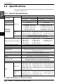
1.2.1 General Specifications ........................................................................................ 1-4
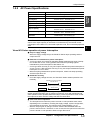
1.2.2 AC Power Specifications .................................................................................... 1-5
Visual KV Series operation at power interruption ........................................ 1-5
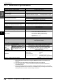
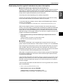
1.2.3 Performance Specifications ................................................................................ 1-6
Data backup function against instantaneous power interruption ................. 1-7
1.3
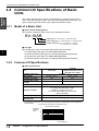
Common I/O Specifications of Basic Units ................................................... 1-8
1.3.1 Model of a Basic Unit .......................................................................................... 1-8
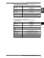
1.3.2 Common I/O Specifications ................................................................................ 1-8
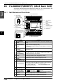
1.4
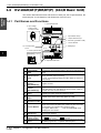
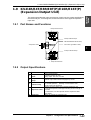
KV-10AR/AT(P)/DR/DT(P) (10-I/O Basic Unit) ............................................. 1-10
1.4.1 Part Names and Functions ............................................................................... 1-10
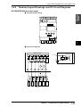
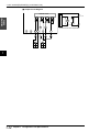
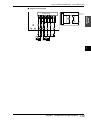
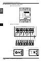
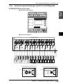
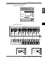
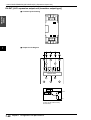
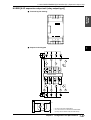
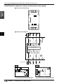
1.4.2 Terminal Layout Drawings and I/O Circuit Diagrams ........................................ 1-11
KV-10AR/DR (Relay output type) .............................................................. 1-11
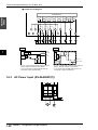
KV-10AT(P)/DT(P) (Transistor output type) ............................................... 1-13
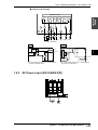
1.4.3 AC Power Input (KV-10AR/AT(P)) .................................................................... 1-14
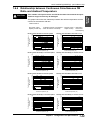
1.4.4 Relationship between Continuous Simultaneous ON Ratio and Ambient Temperature 1-15
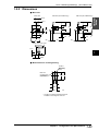
1.4.5 Dimensions ....................................................................................................... 1-16
1.5
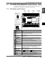
KV-16AR/AT(P)/DR/DT(P) (16-I/O Basic Unit) ............................................. 1-17
1.5.1 Part Names and Functions ............................................................................... 1-17
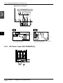
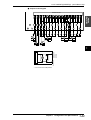
1.5.2 Terminal Layout Drawings and I/O Circuit Diagrams ........................................ 1-18
KV-16AR/DR (Relay output type) .............................................................. 1-18
KV-16AT(P)/DT(P) (Transistor output type) ............................................... 1-20
1.5.3 AC Power Input (KV-16AR/AT(P)) .................................................................... 1-21
1.5.4 Relationship between Continuous Simultaneous ON Ratio and Ambient Temperature 1-22
1.5.5 Dimensions ....................................................................................................... 1-23
1.6
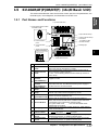
KV-24AR/AT(P)/DR/DT(P) (24-I/O Basic Unit) ............................................. 1-24
1.6.1 Part Names and Functions ............................................................................... 1-24
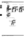
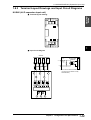
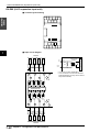
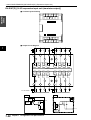
1.6.2 Terminal Layout Drawings and I/O Circuit Diagrams ........................................ 1-25
KV-24AR/DR (Relay output type) .............................................................. 1-25
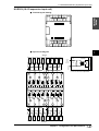
KV-24AT(P)/DT(P) (Transistor output type) ............................................... 1-27
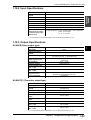
1.6.3 AC Power Input (KV-24AR/AT(P)) .................................................................... 1-28
1.6.4 Relationship between Continuous Simultaneous ON Ratio and Ambient Temperature 1-29
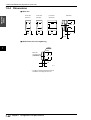
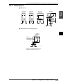
1.6.5 Dimensions ....................................................................................................... 1-30
1.7
KV-40AR/AT(P)/DR/DT(P) (40-I/O Basic Unit) .............................................. 1-31
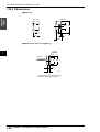
1.7.1 Part Names and Functions ............................................................................... 1-31
1.7.2 Terminal Layout Drawings and I/O Circuit Diagrams ........................................ 1-32
KV-40AR/DR (Relay output type) .............................................................. 1-32
KV-40AT(P)/DT(P) (Transistor output type) ............................................... 1-34
1.7.3 AC Power Input (KV-40AR/AT(P)) .................................................................... 1-35
1.7.4 Relationship between Continuous Simultaneous ON Ratio and Ambient Temperature 1-36
1.7.5 Dimensions ....................................................................................................... 1-37
1.8
1.8.1
1.8.2
1.8.3
KV-E4X/E8X/E16X (Expansion Input Unit) .................................................. 1-38
Part Names and Functions ............................................................................... 1-38
Input Specifications ........................................................................................... 1-38
Terminal Layout Drawings and Input Circuit Diagrams .................................... 1-39
KV-E4X (4-I/O expansion input unit) .......................................................... 1-39
KV-E8X (8-I/O expansion input unit) .......................................................... 1-40
KV-E16X (16-I/O expansion input unit) ...................................................... 1-41
1.8.4 Dimensions ....................................................................................................... 1-42
1.9
KV-E4R/E4T/E8R/E8T(P)/E16R/E16T(P) (Expansion Output Unit) ............. 1-43
1.9.1 Part Names and Functions ............................................................................... 1-43
1.9.2 Output Specifications ........................................................................................ 1-43
KV-E4R/E8R/E16R (Relay output type) ..................................................... 1-44
KV-E4T/E8T(P)/E16T(P) [Transistor output type (NPN/PNP)] .................. 1-44
1.9.3 Terminal Layout Drawings and Input Circuit Diagrams .................................... 1-45
KV-E4R [4-I/O expansion output unit (relay output type)] .......................... 1-45
(9)
KV-E4T [4-I/O expansion output unit transistor output type)] .................... 1-46
KV-E8R [8-I/O expansion output unit (relay output type)] .......................... 1-47
KV-E8T(P) [8-I/O expansion output unit (transistor output type)] .............. 1-48
KV-E16R [16-I/O expansion output unit (relay output type)] ...................... 1-49
KV-E16T(P) [16-I/O expansion input unit (transistor output)] .................... 1-50
1.9.4 Dimensions ....................................................................................................... 1-51
1.10
1.10.1
1.10.2
1.10.3
KV-E4XR/E4XT(P) (Expansion I/O Unit) ....................................................... 1-52
Part Names and Functions ............................................................................... 1-52
Input Specifications ........................................................................................... 1-53
Output Specifications ........................................................................................ 1-53
KV-E4XR (Relay output type) .................................................................... 1-53
KV-E4XT(P) (Transistor output type) ......................................................... 1-53
1.10.4 Terminal Layout Drawings and Input Circuit Diagrams .................................... 1-54
KV-E4XR (Relay output type) .................................................................... 1-54
KV-E4XT(P) (Transistor output type) ......................................................... 1-56
1.10.5 Dimensions ....................................................................................................... 1-58
1.11
1.11.1
1.11.2
1.11.3
1.11.4
Chapter 2
KV-D20 (Operator Interface Panel) ............................................................... 1-59
Part Names and Functions ............................................................................... 1-59
General Specifications ...................................................................................... 1-60
Functional Specifications .................................................................................. 1-60
Dimensions ....................................................................................................... 1-61
System Installation
Visual KV
2.1
2.1.1
2.1.2
2.1.3
Installation Environment ............................................................................... 1-64
Installation Environment ................................................................................... 1-64
Installation Position ........................................................................................... 1-65
Installation Procedure ....................................................................................... 1-66
Expansion unit spacer ................................................................................ 1-66
2.1.4 Cautions on Wiring for Each Unit ...................................................................... 1-67
Wiring procedures for basic units ............................................................... 1-67
Cautions on wiring for I/O units .................................................................. 1-68
Terminal .....................................................................................................1-68
Cautions on grounding ............................................................................... 1-69
2.1.5 Contact Protection ............................................................................................ 1-69
2.2
Connecting Visual KV Series Expansion Units .......................................... 1-70
2.2.1 Visual KV Series Expansion Units .................................................................... 1-70
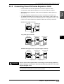
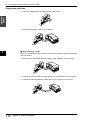
2.2.2 Connecting Visual KV Series Expansion Units ................................................. 1-71
Connection methods .................................................................................. 1-72
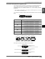
Number of connectable units ..................................................................... 1-73
2.2.3 Confirming the Connection Settings of Expansion Units .................................. 1-74
Expansion unit relay list ............................................................................. 1-74
Connection information for expansion units ............................................... 1-75
Input time constant for expansion units ..................................................... 1-76
Clearing the input value when disconnecting ............................................. 1-76
2.2.4 Transferring I/O Information between Expansion Units and the Basic Unit ...... 1-77
When inputting ........................................................................................... 1-77
In the case of output .................................................................................. 1-77
2.3
Inspection and Maintenance ......................................................................... 1-78
2.3.1 Inspection ......................................................................................................... 1-78
2.3.2 Maintenance .....................................................................................................1-78
Chapter 3
Access Window
Visual KV
3.1
Overview of the Access Window .................................................................. 1-80
3.1.1 What is the Access Window ............................................................................. 1-80
3.1.2 Access Window Use Examples ........................................................................ 1-80
3.2
3.2.1
3.2.2
3.2.3
3.2.4
3.2.5
Basic Operating Procedures ......................................................................... 1-81
Operation Mode ................................................................................................1-81
Access Window Modes ..................................................................................... 1-81
Part Names and Functions of the Access Window ........................................... 1-82
Selecting Modes and Setting/Resetting Key Lock ............................................ 1-82
Turbo Function .................................................................................................. 1-83
3.3
Digital Trimmer Mode .................................................................................... 1-84
3.3.1 Function and Operating Procedure ................................................................... 1-84
(10)
Key operation and screen display .............................................................. 1-84
Function and operating procedure ............................................................. 1-84
3.4
Device Mode ................................................................................................... 1-87
3.4.1 Function and Operating Procedure ................................................................... 1-87
Devices that can be displayed and changed ............................................. 1-87
Key operation and screen display .............................................................. 1-87
Selecting the device and displaying the current value/set value ................ 1-88
Changing a numeric value ......................................................................... 1-89
Holding the setting ..................................................................................... 1-91
3.4.2 Screen Display for Each Device Type .............................................................. 1-91
Data memory (DM) .................................................................................... 1-91
Temporary data memory (TM) ................................................................... 1-91
Timer/counter (T/C) .................................................................................... 1-92
High-speed counter comparator (CTC) ...................................................... 1-92
Trimmer (TRM) .......................................................................................... 1-93
Relay (RLY) ............................................................................................... 1-93
3.5
System Mode .................................................................................................. 1-94
3.5.1 Function and Operating Procedure ................................................................... 1-94
Key operation and screen display .............................................................. 1-94
LOAD mode and SAVE mode .................................................................... 1-96
Display in LOAD/SAVE mode .................................................................... 1-96
3.6
Message Display ............................................................................................ 1-97
3.6.1 Error Messages and Error Status ..................................................................... 1-97
3.6.2 User Messages ................................................................................................. 1-97
How to use the user messages .................................................................. 1-98
Chapter 4
KV-D20 Operator Interface Panel
Visual KV
4.1
4.1.1
4.1.2
4.1.3
Before Operation .......................................................................................... 1-100
Checking Package Contents .......................................................................... 1-100
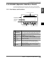
Part Names and Functions ............................................................................. 1-101
Details about the KV-D20 ............................................................................... 1-102
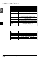
General specifications .............................................................................. 1-102
Functional specifications .......................................................................... 1-102
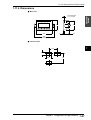
Dimensions .............................................................................................. 1-103
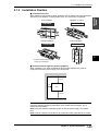
4.1.4 Installation and Environment .......................................................................... 1-104
Use environment ...................................................................................... 1-104
Panel mounting ........................................................................................ 1-105
4.1.5 Inspection and Maintenance ........................................................................... 1-106
Inspection ................................................................................................. 1-106
Maintenance ............................................................................................ 1-106
4.2
Overview and Operation .............................................................................. 1-107
4.2.1 Use Examples for the KV-D20 ........................................................................ 1-107
4.2.2 Connection with the KV Series ....................................................................... 1-108
Connection ...............................................................................................1-108
Precautions .............................................................................................. 1-108
4.2.3 Overview of the KV-D20 ................................................................................. 1-109
Switching the display mode ..................................................................... 1-109
Overview of each display mode ............................................................... 1-110
Assignment of relays/DM ......................................................................... 1-111
Other functions .........................................................................................1-112
Precautions about screen change function .............................................. 1-115
4.2.4 Operator Mode ................................................................................................1-117
Screen selection in operator mode .......................................................... 1-117
Operator screen ....................................................................................... 1-118
Direct access screen ................................................................................ 1-126
KV-I/O monitor screen ............................................................................. 1-127
Switch comment screen ........................................................................... 1-128
Lamp comment screen ............................................................................ 1-128
Screen change permission in operator mode .......................................... 1-129
4.2.5 Device Mode ................................................................................................... 1-130
Device mode ............................................................................................ 1-130
Operation example for device mode ........................................................ 1-132
4.2.6 System Mode .................................................................................................. 1-134
System mode ........................................................................................... 1-134
4.3
(11)
Examples of Ladder Programs ................................................................... 1-135
4.3.1 Basic Ladder Programs .................................................................................. 1-135
Before creating ladder programs ............................................................. 1-135
Basic ladder programs ............................................................................. 1-136
4.3.2 Examples of Ladder Programs ....................................................................... 1-143
Example of displaying user messages ..................................................... 1-143
Example of displaying messages with titles ............................................. 1-145
Example of position control ...................................................................... 1-146
Example of frequency counter ................................................................. 1-149
Example of 24-bit high-speed counter ..................................................... 1-152
Example of cam switch function ............................................................... 1-154
4.4
4.4.1
4.4.2
4.4.3
Chapter 5
Appendix ....................................................................................................... 1-158
Troubleshooting .............................................................................................. 1-158
Available Character List .................................................................................. 1-162
Comment Draft Sheet ..................................................................................... 1-163
KV-300, KV-10/80 Hardware
KV-300, KV-10/80
5.1
System Configuration .................................................................................. 1-166
5.1.1 KV-300 ............................................................................................................ 1-166
5.1.2 KV-10/80 ......................................................................................................... 1-167
5.2
Module/Unit Specifications ......................................................................... 1-168
5.2.1 Wiring: KV-U4 Power Supply Module ............................................................. 1-168
Parts and functions .................................................................................. 1-168
5.2.2 Wiring: KV-U5 DC Power Distribution Module ................................................ 1-169
Parts and functions .................................................................................. 1-169
5.2.3 Wiring: KV-300 CPU ....................................................................................... 1-170
Parts and functions .................................................................................. 1-170
5.2.4 Wiring: KV-C16X/C32X Connector Input Module ........................................... 1-171
Parts and functions .................................................................................. 1-171
5.2.5 Wiring: KV-C32T/B16R/B16S Connector Output Module ............................... 1-172
Parts and functions .................................................................................. 1-172
5.2.6 Wiring: KV-R1A I/O Distribution Module ......................................................... 1-173
Parts and functions .................................................................................. 1-173
5.2.7 Wiring: KV-R8X/R16X/R8R/R16R/R8T/R16T I/O Terminal Modules ............. 1-174
Parts and functions .................................................................................. 1-174
5.2.8 Module Names and Functions ........................................................................ 1-175
5.2.9 Peripheral Equipment Names and Functions ................................................. 1-176
5.3
5.3.1
5.3.2
5.3.3
5.3.4
5.3.5
5.3.6
5.3.7
5.3.8
5.3.9
5.3.10
5.3.11
5.3.12
Chapter 6
Module/Unit Connections ............................................................................ 1-178
Environmental Requirements ......................................................................... 1-178
Installation Guidelines ..................................................................................... 1-178
Assembling the System .................................................................................. 1-179
Connecting modules ................................................................................ 1-179
Mounting to the DIN Rail ................................................................................. 1-180
Removing the Terminal Block ......................................................................... 1-181
Connecting the AC Power Supply Module and DC Power Distribution Module .... 1-182
KV-U4 AC Power Supply Module ............................................................ 1-182
KV-U5 DC Power Distribution Module ..................................................... 1-182
I/O Connectors ................................................................................................ 1-183
KV-300 CPU ............................................................................................ 1-183
KV-C16X/C32X ........................................................................................ 1-184
KV-C32T/B16R/B16S .............................................................................. 1-185
KV-R8X/R16X/R8R/R16R/R8T/R16T ...................................................... 1-186
I/O Terminal Modules: Communication Cables and Power Distribution ......... 1-187
Transmission distance by cable type ....................................................... 1-187
Connection patterns ................................................................................. 1-187
Incorrect wiring patterns ........................................................................... 1-188
Power distribution .................................................................................... 1-188
Connector Assembly Instructions ................................................................... 1-189
KV-300 CPU I/O Indicators ............................................................................. 1-191
KV-10/80 Expansion Units .............................................................................. 1-192
Mounting Environment .................................................................................... 1-194
Handheld Programmer
6.1
Using the Handheld Programmer ............................................................... 1-196
6.1.1 Outline of the Handheld Programmer ............................................................. 1-196
(12)
6.1.2 Precautions .....................................................................................................1-198
6.2
Basic Operations .........................................................................................1-200
6.2.1 Basic Programming Operation ........................................................................ 1-200
6.3
Functions ......................................................................................................1-216
Function Nos. list ..................................................................................... 1-216
ALL CLEAR .............................................................................................. 1-217
HANDHELD PROGRAMMER CLEAR ..................................................... 1-217
COUNTER CLEAR .................................................................................. 1-218
HIGH-SPEED COUNTER CLEAR ........................................................... 1-218
ALL DATA MEMORY CLEAR .................................................................. 1-219
ALL LATCHING RELAYS RESET ........................................................... 1-219
PROGRAM SENT OR RECEIVED .......................................................... 1-220
OFFLINE EDITOR START ...................................................................... 1-221
OFFLINE EDITOR STOP ........................................................................ 1-221
TIMER/COUNTER CURRENT VALUE CHANGE ................................... 1-222
TIMER/COUNTER SETTING CHANGE .................................................. 1-224
RELAY ON/OFF ....................................................................................... 1-226
WRITE INTO DATA MEMORY ................................................................ 1-227
READ TRIMMER SETTING ..................................................................... 1-228
SYNTAX CHECK ..................................................................................... 1-228
PROGRAM CAPACITY CHECK .............................................................. 1-229
6.4
Memory Card ................................................................................................1-230
6.4.1 Functions [used with KV-P3E(01)] .................................................................. 1-230
6.4.2 Storage Capacity ............................................................................................ 1-230
CLEAR .....................................................................................................1-232
NEW ......................................................................................................... 1-233
ACCS ....................................................................................................... 1-234
ACCS: SAVE ........................................................................................... 1-235
ACCS: LOAD ........................................................................................... 1-236
ACCS: VERIFY ........................................................................................ 1-236
ACCS: DELETE ....................................................................................... 1-237
Chapter 7
KV-L2 Serial Interface Module
KV-300
7.1
Outline ......................................................................................................... 1-240
7.1.1 Features .......................................................................................................... 1-240
7.2
7.2.1
7.2.2
7.2.3
Configuration ...............................................................................................1-241
Parts and Functions ........................................................................................ 1-241
System Configuration ..................................................................................... 1-242
Outline of Operation Modes ............................................................................ 1-244
7.3
7.3.1
7.3.2
7.3.3
7.3.4
Installation .................................................................................................... 1-245
Setting the Operation Mode ............................................................................ 1-245
Communications Protocols ............................................................................. 1-247
Connector Wiring ............................................................................................ 1-248
Connecting to External Units .......................................................................... 1-249
Connecting to An External Display .......................................................... 1-249
Connecting to an IBM PC-AT Computer .................................................. 1-249
Connecting to the KV-10/16/24/40/80 ...................................................... 1-250
Connecting KV-L2s .................................................................................. 1-250
7.4
Software Setup ............................................................................................. 1-252
7.4.1 Using KV Software [KV IncrediWare (DOS)] .................................................. 1-252
Starting KV IncrediWare (DOS) from the KV-L2 ........................................................ 1-252
7.5
KV Mode Programming ............................................................................... 1-253
7.5.1 Operating in KV Mode .................................................................................... 1-253
Communications protocol ........................................................................ 1-253
7.5.2 Serial Communications Procedure ................................................................. 1-255
Command transmission procedure .......................................................... 1-255
Command/response format ..................................................................... 1-256
Communications commands and responses ........................................... 1-256
Communications commands .................................................................... 1-257
7.5.3 Transmission and Reception of Text Data ...................................................... 1-262
Assigning relay nos. and data memory address nos. .............................. 1-262
Transmitting Text Data ............................................................................. 1-264
Receiving text data .................................................................................. 1-265
ASCII code/binary conversion function .................................................... 1-266
(13)
Example program ..................................................................................... 1-269
7.6
Display Interface Mode Programming ....................................................... 1-270
7.6.1 Operating in Display Interface Mode .............................................................. 1-270
Communications protocols ....................................................................... 1-270
Communications control procedure ......................................................... 1-271
7.6.2 Command and Response Format ................................................................... 1-273
7.6.3 Commands and Responses ........................................................................... 1-275
List of commands and responses ............................................................ 1-275
Description of commands and responses ................................................ 1-277
End codes ................................................................................................ 1-291
7.7
Non-procedure Mode Programming .......................................................... 1-292
7.7.1 Operating in Non-procedure Mode ................................................................. 1-292
Communications protocol ........................................................................ 1-292
Connecting to the KV-L2 .......................................................................... 1-293
7.7.2 Assignment of Relay Nos. and Data Memory Address Nos. .......................... 1-294
Assigning relay nos. and data memory address nos. .............................. 1-294
7.7.3 Transmitting Text Data ................................................................................... 1-297
Data transmission and internal data memory addresses ......................... 1-297
7.7.4 Receiving Text Data ....................................................................................... 1-298
Format of received data and data memory addresses ............................ 1-298
7.7.5 ASCII code/Binary Conversion Function ........................................................ 1-300
7.8
Troubleshooting Guide ............................................................................... 1-304
7.8.1 Troubleshooting .............................................................................................. 1-304
7.8.2 Precautions ..................................................................................................... 1-305
7.9
Specifications ............................................................................................... 1-306
7.9.1 Specifications .................................................................................................. 1-306
General specifications .............................................................................. 1-306
Communications protocol ........................................................................ 1-306
RS-232C connector specifications ........................................................... 1-306
RS-422A terminal block specifications ..................................................... 1-306
7.9.2 Dimensions ..................................................................................................... 1-307
7.10 Command List .............................................................................................. 1-308
7.10.1 List of Commands and Responses ................................................................. 1-308
7.10.2 List of Commands and Responses in Display Interface mode ....................... 1-309
Chapter 8
KV-AN6 Analog I/O Module
8.1
KV-300
Outline ......................................................................................................... 1-312
Features ................................................................................................... 1-312
8.2
Configuration ............................................................................................... 1-313
8.2.1 Parts and Functions ........................................................................................ 1-313
8.2.2 System Configuration ..................................................................................... 1-314
8.3
8.3.1
8.3.2
8.3.3
8.3.4
8.3.5
Installation .................................................................................................... 1-315
Terminal Nos. ................................................................................................. 1-315
Removing the Terminal Block ......................................................................... 1-316
Example of Voltage I/O Wiring ........................................................................ 1-317
Example of Current I/O Wiring ........................................................................ 1-318
Setting I/O Ranges ......................................................................................... 1-319
8.4
8.4.1
8.4.2
8.4.3
8.4.4
8.4.5
8.4.6
8.4.7
8.4.8
8.4.9
Programming ................................................................................................ 1-320
Input Characteristics (A/D) .............................................................................. 1-320
Calculating Input Data (A/D) ........................................................................... 1-321
Output Characteristics (D/A) ........................................................................... 1-322
Calculating Output Data (D/A) ........................................................................ 1-323
Assigning Data Memory (DM) Addresses ....................................................... 1-324
Reading Analog Input ..................................................................................... 1-325
Measuring Analog Input Average ................................................................... 1-326
Writing Analog Output ..................................................................................... 1-327
Converting Analog Input to Analog Output ..................................................... 1-328
8.5
8.5.1
8.5.2
8.5.3
KV-AN6 Appendices .................................................................................... 1-329
Troubleshooting .............................................................................................. 1-329
Precautions ..................................................................................................... 1-330
Specifications .................................................................................................. 1-331
Environmental specifications ................................................................... 1-331
System specifications .............................................................................. 1-331
(14)
8.5.4 Dimensions .....................................................................................................1-332
Chapter 9
KV-AD4/DA4 Analog I/O Unit
9.1
KV-10/80
Outline ......................................................................................................... 1-334
Features ................................................................................................... 1-334
9.2
Configuration ...............................................................................................1-335
9.2.1 Part Names and Functions ............................................................................. 1-335
KV-AD4 .................................................................................................... 1-335
KV-DA4 .................................................................................................... 1-336
9.2.2 Specifications .................................................................................................. 1-337
KV-AD4 .................................................................................................... 1-337
KV-DA4 .................................................................................................... 1-339
9.2.3 System Configuration ..................................................................................... 1-341
9.3
9.3.1
9.3.2
9.3.3
Installation .................................................................................................... 1-342
Installation Procedure ..................................................................................... 1-342
Checking the Installation Environment ........................................................... 1-343
Setting the KV-AD4 Input Mode ...................................................................... 1-344
Setting the input mode ............................................................................. 1-344
9.3.4 Connecting External Instruments .................................................................... 1-345
Wiring ....................................................................................................... 1-345
Wiring diagrams ....................................................................................... 1-346
9.3.5 Connecting to the KV-10 to 80 ........................................................................ 1-348
9.3.6 Maintenance ................................................................................................... 1-349
Inspection and Cleaning .......................................................................... 1-349
9.4
Programming ................................................................................................1-350
9.4.1 Programming the KV-AD4 .............................................................................. 1-350
A/D Conversion Mechanism .................................................................... 1-350
About Digital Data after A/D Conversion .................................................. 1-351
Calculating Voltage and Current Values from Digital Data ...................... 1-352
9.4.2 Programming the KV-DA4 .............................................................................. 1-353
D/A Conversion Mechanism .................................................................... 1-353
Converting Digital Data to Voltage or Current Values to be Output ......... 1-354
Writing Digital Data to Data Memory for D/A Conversion ........................ 1-356
9.4.3 A/D and D/A Conversion Tables ..................................................................... 1-357
Voltage Conversion Table ........................................................................ 1-357
Current Conversion Table ........................................................................ 1-358
Chapter 10
9.5
Programming Examples .............................................................................. 1-359
Calculating Analog Data Values from Digital Data ................................... 1-359
Writing Data to be Analog-output ............................................................. 1-361
Outputting Analog Trimmer Values .......................................................... 1-364
Outputting Analog Input Data ................................................................... 1-365
Outputting Analog Input from a Pressure Sensor to an Air Valve ............ 1-366
Setting the Minimum and Maximum Voltage Limits and Measuring the
Average Voltage ...................................................................................... 1-367
9.6
Troubleshooting ........................................................................................... 1-370
Troubleshooting
10.1
10.1.1
10.1.2
10.1.3
10.1.4
Error List ....................................................................................................... 1-372
List of Error Codes in Basic Units ................................................................... 1-372
Error indication in Expansion Units ................................................................. 1-374
Program Errors ...............................................................................................1-375
Memory Card Errors and Other Errors ........................................................... 1-376
10.2
Replacing Relays .........................................................................................1-377
Replacement procedure ........................................................................... 1-377
10.3 Troubleshooting ........................................................................................... 1-378
10.3.1 Troubleshooting List ....................................................................................... 1-378
10.4
Error Messages ............................................................................................ 1-380
Appendices
Appendix A. Specifications and Dimensions [Visual KV Series] .................... 1-382
A.1
System Specifications [Visual KV Series] ....................................................... 1-382
(15)
A.2
A.3
A.4
Hardware ................................................................................................. 1-382
Software and Programming ..................................................................... 1-383
AC power supply unit ............................................................................... 1-384
Common I/O Specifications of Basic Units ..................................................... 1-384
Input specifications .................................................................................. 1-384
Output specifications (relay output): KV-10AR/DR, KV-16AR/DR,
KV-24AR/DR, and KV-40AR/DR .............................................................. 1-385
Output specifications (transistor output): KV-10AT(P)/DT(P),
KV-16AT(P)/DT(P), KV-24AT(P)/DT(P), and KV-40AT(P)/DT(P) ............ 1-385
Expansion Unit Specifications ........................................................................ 1-385
Dimensions ..................................................................................................... 1-389
Appendix B. Specifications and Dimensions [KV-300 Series] ......................... 1-392
B.1
System Specifications [KV-300 Series] .......................................................... 1-392
Hardware ................................................................................................. 1-392
Software and Programming ..................................................................... 1-393
AC Power supply module/DC power distribution module ........................ 1-394
B.2
Module Specifications ..................................................................................... 1-398
KV-300 CPU ............................................................................................ 1-398
KV-C16X/C32X Input Modules ................................................................ 1-399
KV-C32T/B16R/B16S Output Modules ................................................... 1-400
KV-R8X/R16X I/O Terminal Modules ....................................................... 1-401
KV-R8T/R16T/R8R/R16R I/O Terminal Modules ..................................... 1-402
KV-R8T/R16T/R8R/R16R I/O Terminal Modules (RUN Output) .............. 1-403
KV-R1A I/O Distribution Module .............................................................. 1-403
B.3
Dimensions ..................................................................................................... 1-404
Appendix C.
Ladder Program List ...................................................................... 1-406
Appendix D. A/D and D/A Conversion Tables [KV-AN6] ..................................... 1-408
Voltage conversion table .......................................................................... 1-408
Current conversion table .......................................................................... 1-409
WARRANTIES AND DISCLAIMERS
2
1-419
Support software
Chapter 1
Introduction
1.1
Items Included in the Package ........................................................................ 2-2
1.2
Outline of the Ladder Builder for KV .............................................................. 2-3
1.2.1 Operating environment and system configuration .............................................. 2-3
1.2.2 Features and functions of the Ladder Builder for KV .......................................... 2-4
Features of the Ladder Builder for KV ......................................................... 2-4
Functions of the Ladder Builder for KV ........................................................ 2-6
1.3
Before Programming ....................................................................................... 2-7
Machines to be prepared ............................................................................. 2-7
1.3.1 Differences from the KV IncrediWare (DOS) ...................................................... 2-8
1.3.2 Differences from the Ladder Builder for KV Ver 1.0 ........................................... 2-8
1.4
Installing the Software ..................................................................................... 2-9
1.4.1 Preparation for installation .................................................................................. 2-9
1.4.2 Installation Procedure ....................................................................................... 2-10
Installation in Windows 95 ......................................................................... 2-10
Installation in Windows 3.1 ........................................................................ 2-12
Chapter 2
1.5
Cautions for Use ............................................................................................ 2-13
1.6
1.6.1
1.6.2
1.6.3
1.6.4
1.6.5
Basic Operations ........................................................................................... 2-14
Program creation flow and available modes ..................................................... 2-14
Starting up and exiting from the software ......................................................... 2-16
Screen .............................................................................................................. 2-18
Mouse operation and keyboard operation ........................................................ 2-21
Online Help ....................................................................................................... 2-23
Editor
KV-300
2.1
Outline of the Editor Functions .................................................................... 2-26
2.1.1 Cautions for editing ladder programs ................................................................ 2-26
2.2
Edit Screen .....................................................................................................2-27
(16)
2.2.1 Name and function of each part of the screen .................................................. 2-27
2.2.2 Ladder program window screen ....................................................................... 2-28
2.3
2.3.1
2.3.2
2.3.3
2.3.4
2.3.5
2.3.6
2.3.7
File Management ............................................................................................ 2-29
Creating a new file ............................................................................................ 2-29
Setting the automatic file read function ............................................................. 2-30
Setting automatic file save for the file ............................................................... 2-31
Saving and reading files ................................................................................... 2-32
Reading and saving a file in another format ..................................................... 2-33
Saving a ladder diagram in text format ............................................................. 2-36
Verifying files .................................................................................................... 2-36
2.4
2.4.1
2.4.2
2.4.3
2.4.4
2.4.5
2.4.6
Entering/Deleting Symbols and Connection Lines .................................... 2-37
Entering symbols .............................................................................................. 2-37
Deleting symbols .............................................................................................. 2-42
Entering contacts/coils directly ......................................................................... 2-42
Changing the device at the current cursor position .......................................... 2-43
Entering/Deleting connection lines ................................................................... 2-44
Canceling edit operations ................................................................................. 2-45
2.5
2.5.1
2.5.2
2.5.3
Entering Comments/Labels ......................................................................... 2-46
Editing comments/labels ................................................................................... 2-46
Editing line comments ....................................................................................... 2-50
Changing ladder lines into comments ............................................................... 2-51
2.6
Edit and Arrangement .................................................................................. 2-52
2.6.1 Copy, move, and delete .................................................................................... 2-52
2.6.2 Inserting and deleting lines ............................................................................... 2-57
2.7
2.7.1
2.7.2
2.7.3
2.7.4
2.7.5
Jump, Search, and Replace ......................................................................... 2-58
Jump ................................................................................................................. 2-58
Searching for instruction words/operands ........................................................ 2-62
Searching for the device at the cursor position ................................................. 2-63
Replacing operands .......................................................................................... 2-64
Converting a/b contacts .................................................................................... 2-65
2.8
Editing the Mnemonic List ........................................................................... 2-67
2.8.1 Displaying and terminating a mnemonic list ..................................................... 2-67
2.8.2 Copy, move, and delete .................................................................................... 2-69
2.9
Displaying the Use Status ............................................................................. 2-70
2.9.1 Displaying a use status list ............................................................................... 2-70
2.10 Setting the System ......................................................................................... 2-71
2.10.1 Setting the system ............................................................................................ 2-71
2.11 Entering and Developing Macros ................................................................ 2-72
2.11.1 Creating a macro file ......................................................................................... 2-72
2.11.2 Entering and developing macros ...................................................................... 2-74
2.12
2.12.1
2.12.2
2.12.3
Compilation .................................................................................................... 2-75
Executing compilation ....................................................................................... 2-75
Error display ...................................................................................................... 2-76
Double coil check .............................................................................................. 2-76
2.13 Printing Functions ......................................................................................... 2-77
2.13.1 Printing .............................................................................................................. 2-77
2.13.2 Preview display ................................................................................................. 2-81
2.14 Changing the Display Color on the Screen ................................................. 2-82
2.14.1 Changing display colors on the screen ............................................................. 2-82
Chapter 3
Simulator
3.1
Outline of the Simulator Functions .............................................................. 2-84
3.1.1 Outline of the functions ..................................................................................... 2-84
3.1.2 Restrictions in the simulator .............................................................................. 2-84
3.2
Starting up and Exiting from the Simulator ................................................. 2-86
3.2.1 Operating procedure for startup and exit .......................................................... 2-86
3.2.2 Name and function of each part of the screen .................................................. 2-88
3.3
3.3.1
3.3.2
3.3.3
(17)
Ladder Monitor ............................................................................................... 2-89
Outline of the ladder monitor ............................................................................ 2-89
Executing scans ................................................................................................ 2-89
Executing steps .............................................................................................. 2-101
3.3.4 Jump and search ............................................................................................ 2-105
3.3.5 Stop/reset and device all clear ........................................................................ 2-108
Chapter 4
3.4
3.4.1
3.4.2
3.4.3
3.4.4
3.4.5
Monitor All .................................................................................................... 2-109
Outline of monitor all ....................................................................................... 2-109
Displaying, saving, and reading the monitor all window ................................. 2-109
Monitor all window .......................................................................................... 2-113
Registering devices ........................................................................................ 2-113
Selecting and changing devices ..................................................................... 2-116
3.5
3.5.1
3.5.2
3.5.3
3.5.4
3.5.5
3.5.6
3.5.7
Registration Monitor .................................................................................... 2-119
Outline of the registration monitor ................................................................... 2-119
Displaying, saving, and reading the registration monitor ................................ 2-119
Registration monitor window ........................................................................... 2-122
Registering devices ........................................................................................ 2-122
Selecting and changing devices ..................................................................... 2-123
Manipulating timing charts .............................................................................. 2-128
Printing out the registration monitor ................................................................ 2-131
Monitor
4.1
4.1.1
4.1.2
4.1.3
Outline of the Monitor Functions ............................................................... 2-134
Outline of the functions ................................................................................... 2-134
Restrictions in the monitor .............................................................................. 2-134
Precautions for communication ...................................................................... 2-135
4.2
Communicating with the PLC ..................................................................... 2-136
4.2.1 Setting the PLC communication parameters .................................................. 2-136
4.2.2 Setting the comment transfer .......................................................................... 2-138
4.3
Starting up and Exiting from the Monitor .................................................. 2-139
4.3.1 Operating procedures for startup and exit ...................................................... 2-139
4.3.2 Name and function of each part of the screen ................................................ 2-143
4.4
4.4.1
4.4.2
4.4.3
4.4.4
4.4.5
4.4.6
4.4.7
Ladder Monitor ............................................................................................. 2-144
Outline of the ladder monitor .......................................................................... 2-144
Displaying the ladder monitor window ............................................................ 2-144
PLC error check .............................................................................................. 2-144
Starting the monitor ........................................................................................ 2-145
Stopping the monitor ....................................................................................... 2-145
Screen displayed while the monitor is running ............................................... 2-146
Setting the PLC operation mode ..................................................................... 2-147
4.5
Monitor All and Registration Monitor ......................................................... 2-148
4.5.1 Functions of the monitor all window ................................................................ 2-148
4.5.2 Functions of the registration monitor .............................................................. 2-148
4.6
4.6.1
4.6.2
4.6.3
Monitor Function .......................................................................................... 2-149
Disabling the input refresh/Disabling the output ............................................. 2-149
Changing the current values all at once ......................................................... 2-150
Device all clear ............................................................................................... 2-154
Appendices
Appendix A Error Message List ......................................................................... 2-156
A-1
System errors ................................................................................................. 2-156
A-2
Memory errors ................................................................................................ 2-156
A-3
File errors ........................................................................................................ 2-157
A-4
Installation errors ............................................................................................ 2-157
A-5
Errors that occur in the editor ......................................................................... 2-158
A-6
Errors that occur in the monitor/simulator ....................................................... 2-159
A-7
Communication errors (displayed in the monitor) ........................................... 2-159
A-8
PLC errors ...................................................................................................... 2-160
A-9
Errors that occur during compilation ............................................................... 2-161
Appendix B Instruction List ............................................................................... 2-163
B-1
Basic instructions ............................................................................................ 2-163
B-2
Application instructions ................................................................................... 2-164
B-3
Arithmetic instructions ..................................................................................... 2-165
B-4
Interrupt instructions ....................................................................................... 2-166
Appendix C Relay No. List .................................................................................. 2-167
C-1
Relays, timers, counters, and memory numbers for each model ................... 2-167
(18)
Appendix D Special Utility Relay List ................................................................ 2-168
D-1
Special relays and arithmetic operation flags ................................................. 2-168
D-2
Special utility relays for high-speed counter (0) .............................................. 2-168
D-3
Special utility relays for high-speed counter (1) .............................................. 2-169
D-4
Other special utility relays ............................................................................... 2-169
D-5
Memory switches ............................................................................................ 2-172
D-6
Special memory list .........................................................................................2-172
Appendix E Devices for KV-10R(W)/T(W) to 80R(W)/T(W), KV-300 ................ 2-174
E-1
Special utility relays ........................................................................................ 2-174
E-2
Memory switches ............................................................................................ 2-176
E-3
Special memory list .........................................................................................2-176
Appendix F Sample Program List ..................................................................... 2-178
F-1
Description of sample ladder programs .......................................................... 2-178
Appendix G Quick Reference ............................................................................. 2-180
G-1 Editor .............................................................................................................. 2-180
G-2 Simulator ......................................................................................................... 2-188
G-3 Monitor ............................................................................................................2-195
Appendix H Notes for Programming ................................................................. 2-201
H-1
Circuits that must be modified ........................................................................ 2-201
H-2
Precautions for programming ......................................................................... 2-202
H-3
Programs which cannot be decompiled .......................................................... 2-203
Appendix I
List of Files Used ............................................................................ 2-204
Appendix J
Countermeasures for Frequent Communication Errors ............ 2-205
WARRANTIES AND DISCLAIMERS
3
2-215
Programming
Chapter 1
Programming
1.1
Before Creating Programs .............................................................................. 3-2
1.1.1 Flow from Introduction to Operation ................................................................... 3-2
1.1.2 Scan Time ........................................................................................................... 3-3
Scan time ..................................................................................................... 3-3
Input response time delay ............................................................................ 3-3
1.2
User Memory .................................................................................................... 3-4
1.2.1 Program Capacity ............................................................................................... 3-4
Maximum number of lines in a program ....................................................... 3-4
Calculating the byte count used ................................................................... 3-4
1.3
Device Configuration ....................................................................................... 3-5
1.3.1 Device List .......................................................................................................... 3-5
Relay list ...................................................................................................... 3-5
List of I/O relays in basic units ..................................................................... 3-5
List of relays in expansion units ................................................................... 3-6
1.3.2 Relay No. ............................................................................................................ 3-7
Address No. ................................................................................................. 3-7
Contact No. .................................................................................................. 3-8
Channel No. ................................................................................................. 3-8
1.3.3 Assigning Relay Nos. .......................................................................................... 3-8
1.3.4 Input Relays ........................................................................................................ 3-9
Basic unit ..................................................................................................... 3-9
Expansion unit ........................................................................................... 3-10
1.3.5 Output Relays ................................................................................................... 3-10
Output operation time ................................................................................ 3-10
1.3.6 Internal Utility Relays ........................................................................................ 3-11
Retentive function of internal utility relays .................................................. 3-11
1.3.7 Special Utility Relays ........................................................................................ 3-12
Description ................................................................................................. 3-12
1.3.8 Special Utility Relay List ................................................................................... 3-14
Special relays and arithmetic operation flags ............................................ 3-14
Special utility relays for high-speed counter(0) .......................................... 3-14
Special utility relays for high-speed counter(1) .......................................... 3-15
Other special utility relays .......................................................................... 3-15
1.3.9 Timers and Counters ........................................................................................ 3-18
(19)
Timer/Counter list ....................................................................................... 3-18
Description ................................................................................................. 3-18
1.3.10 Data Memories ................................................................................................. 3-19
1.3.11 Temporary Data Memory .................................................................................. 3-21
1.3.12 Relay Nos. and Functions ................................................................................. 3-22
1.4
Special Functions .......................................................................................... 3-23
1.4.1 Input Time Constant Change Function ............................................................. 3-23
Setting the input time constant for basic units using special utility relays .. 3-23
1.4.2 Modifying the Input Relay Time Constant ......................................................... 3-24
Modification within the CPU ....................................................................... 3-24
1.4.3 Constant Scan Time Mode ............................................................................... 3-25
1.4.4 Output Disabled Function ................................................................................. 3-26
1.4.5 Input Refresh Disabled Function ...................................................................... 3-26
1.4.6 Contact Comment Save Function ..................................................................... 3-27
1.4.7 Special Functions ............................................................................................. 3-28
Constant Scan Time Mode ........................................................................ 3-28
Output Disabled Function .......................................................................... 3-28
Input Refresh Disabled Function ................................................................ 3-28
1.5
1.5.1
1.5.2
1.5.3
Chapter 2
Chapter 3
Extended Ladder Diagrams .......................................................................... 3-29
Features of Extended Ladder Diagrams ........................................................... 3-29
Advantages of Extended Ladder Diagrams ...................................................... 3-30
Example of an Extended Ladder Diagram ........................................................ 3-31
Instructions
2.1
2.1.1
2.1.2
2.1.3
2.1.4
2.1.5
Instruction List [Visual KV Series] .............................................................. 3-34
Basic Instructions .............................................................................................. 3-34
Application Instructions ..................................................................................... 3-36
Arithmetic Instructions ...................................................................................... 3-38
Interrupt Instructions .........................................................................................3-41
Function No. List (Alphabetical order) .............................................................. 3-41
2.2
2.2.1
2.2.2
2.2.3
2.2.4
Instruction List [KV-300 Series, KV-10/80] ................................................. 3-42
Basic Instructions .............................................................................................. 3-42
Application Instructions ..................................................................................... 3-45
Arithmetic Instructions ...................................................................................... 3-48
Interrupt Instructions .........................................................................................3-54
2.3
Convention Details ........................................................................................ 3-55
2.4
2.4.1
2.4.2
2.4.3
Instruction Details .......................................................................................... 3-56
Basic Instructions .............................................................................................. 3-56
Application Instructions ..................................................................................... 3-95
Arithmetic Instructions .................................................................................... 3-134
2.5
Programming Notes ..................................................................................... 3-189
Interrupts
Visual KV
3.1
Interrupt Instructions ................................................................................... 3-192
3.2
3.2.1
3.2.2
3.2.3
3.2.4
Interrupt Processing .................................................................................... 3-194
Interrupt Processing ........................................................................................ 3-194
Types of Interrupts .......................................................................................... 3-195
Interrupt Priority .............................................................................................. 3-196
Interrupt Program ............................................................................................ 3-196
3.3
Direct Input/Output ...................................................................................... 3-197
3.3.1 Direct Input ..................................................................................................... 3-197
3.3.2 Direct Output ................................................................................................... 3-197
3.4
3.4.1
3.4.2
3.4.3
3.4.4
Chapter 4
Applications of Interrupt Programs ........................................................... 3-198
Interrupt with a Signal Converter .................................................................... 3-198
Interrupt with a High-speed Counter ............................................................... 3-199
Measuring the ON Time of High-speed Pulses .............................................. 3-200
Measuring the Period in which a Target Passes between Two Points ........... 3-201
High-speed Counters
Visual KV
4.1
High-speed Counter Instructions ............................................................... 3-204
4.2
Outline of High-speed Counters ................................................................. 3-206
(20)
4.2.1 High-speecÛCounters and High-speed Counter Comparators ...................... 3-206
Structure of high-speed counters and high-speed counter comparators . 3-206
Specifications of high-speed counters ..................................................... 3-208
High-speed counter comparators ............................................................. 3-209
4.2.2 Internal Clock for High-speed Counters .......................................................... 3-210
4.3
4.3.1
4.3.2
4.3.3
4.3.4
4.3.5
4.3.6
Setting and Operation of High-speed Counters ........................................ 3-211
Reading the Current Value of the High-speed Counter .................................. 3-211
Preset Value of the High-speed Counter Comparator .................................... 3-211
Comparator Output .........................................................................................3-211
Count Input Method ........................................................................................ 3-212
Resetting the High-speed Counter ................................................................. 3-214
Differences with the CTH Instruction between the
Conventional and Visual KV Series ................................................................ 3-216
4.3.7 Applications of High-speed Counters ............................................................. 3-217
4.4
4.4.1
4.4.2
4.4.3
4.4.4
4.4.5
Extended Functions of High-speed Counters ........................................... 3-221
24-bit High-speed Counter .............................................................................. 3-221
Changing the Current Value of a 24-bit High-speed Counter ......................... 3-223
Application Example of 24-bit High-speed Counter (single-phase input) ....... 3-224
Ring Counter Function .................................................................................... 3-225
Applications of Ring Counters ........................................................................ 3-226
4.5
4.5.1
4.5.2
4.5.3
4.5.4
4.5.5
Special Functions Using High-speed Counters ........................................ 3-228
Specified Frequency Pulse Output Function .................................................. 3-228
Applications of the Specified Frequency Pulse Output ................................... 3-229
Frequency Counter Function .......................................................................... 3-231
Applications of Frequency Counters ............................................................... 3-232
Cam Switch Function ...................................................................................... 3-233
Cam switch mode .................................................................................... 3-233
Multi-step comparator mode .................................................................... 3-234
Setting method .........................................................................................3-234
4.5.6 Application of the Cam Switch (Cam Switch Mode) ....................................... 3-236
4.6
Direct Clock Pulse Output ........................................................................... 3-237
4.6.1 Outline of Direct Clock Pulse Output .............................................................. 3-237
4.6.2 Pulse Output Setting with the High-speed Counter Comparator .................... 3-238
Changing the pulse period and width ....................................................... 3-238
Calculating the pulse period and comparator preset value ...................... 3-239
Operation with special utility relays .......................................................... 3-239
4.7
4.7.1
4.7.2
4.7.3
4.7.4
Chapter 5
Examples of Direct Clock Pulse Output .................................................... 3-242
Example of Outputting a Pulse with 1:1 ON/OFF Ratio .................................. 3-242
Example of Outputting a Pulse with Variable ON/OFF Ratio .......................... 3-245
Example of Stopping the Pulse Output at a Specified Pulse Count ............... 3-249
Application of Direct Clock Pulse Output (Ramp-up/down control) ................ 3-251
Positioning Control
Visual KV
5.1
Outline of Positioning Control .................................................................... 3-254
5.1.1 Ramp-up/down Control ................................................................................... 3-254
5.2
Parameter Setting and Operating Procedures .......................................... 3-255
5.2.1 Parameter Setting Procedure ......................................................................... 3-255
5.2.2 Operating Procedure ...................................................................................... 3-257
5.3
5.3.1
5.3.2
5.3.3
Chapter 6
Examples of Using the Positioning Control Function .............................. 3-258
Connection Example ....................................................................................... 3-258
Tips .................................................................................................................3-258
Application Examples of the Positioning Control Function ............................. 3-259
Interrupts, High-speed Counters,
Positioning Control
KV-300, KV-10/80
6.1
Interrupt Instructions ................................................................................... 3-268
6.1.1 Description of Interrupts .................................................................................. 3-268
Input processing for routine program and interrupt routine ...................... 3-268
Types of interrupt ..................................................................................... 3-268
Interrupt priority ........................................................................................ 3-269
Interrupt routine ........................................................................................ 3-269
Direct output ............................................................................................. 3-270
Direct input ...............................................................................................3-270
(21)
6.1.2 Interrupt Instructions ....................................................................................... 3-271
6.2
Direct Clock Pulse ........................................................................................ 3-276
6.2.1 Output of Direct Clock Pulse ........................................................................... 3-276
Outline of High-Speed Counters .............................................................. 3-276
Outline of Pulse Output ............................................................................ 3-279
Examples of Pulse Output ....................................................................... 3-284
6.3
Positioning Control ...................................................................................... 3-296
6.3.1 Positioning Control (Ramp-up/down Control) ................................................. 3-296
Outline of positioning control .................................................................... 3-296
Setting and application of parameters ..................................................... 3-297
Examples of stepping motor control ......................................................... 3-300
Chapter 7
Chapter 8
Serial Communication
7.1
7.1.1
7.1.2
7.1.3
Communications Specifications ................................................................ 3-306
Communications Specification ........................................................................ 3-306
Connection with the KV Unit ........................................................................... 3-306
Connecting the KV-300 CPU to a Personal Computer ................................... 3-307
7.2
7.2.1
7.2.2
7.2.3
7.2.4
7.2.5
7.2.6
7.2.7
Serial Communication ................................................................................. 3-308
Command Transmission Procedure ............................................................... 3-308
Format of Commands/Responses .................................................................. 3-309
Communication Command/Response List ..................................................... 3-310
Setting Communication Commands and Responses to Commands .............. 3-311
Other Response Codes .................................................................................. 3-315
Error Code List ................................................................................................ 3-316
Example Program ........................................................................................... 3-317
7.3
7.3.1
7.3.2
7.3.3
Loading Text Data ........................................................................................ 3-318
Receiving Text Data ....................................................................................... 3-318
Transmitting Text Data ................................................................................... 3-319
Sample Program ............................................................................................. 3-320
7.4
ASCII Code List ............................................................................................ 3-321
Programming Examples
8.1
List
......................................................................................................... 3-324
8.2
Details ......................................................................................................... 3-326
8.2.1 Reference Program Examples ........................................................................ 3-326
Basic Instructions ..................................................................................... 3-326
Application Instructions ............................................................................ 3-334
Arithmetic Instructions .............................................................................. 3-343
WARRANTIES AND DISCLAIMERS
3-367
(22)
WARRANTIES AND DISCLAIMERS
See 1-419.
Caution
•
No part of this manual may be reprinted or reproduced in any form or by any
means without the prior written permission of KEYENCE CORPORATION.
•
The content of this manual is subject to change without notice.
•
KEYENCE has thoroughly checked and reviewed this manual. Please contact
the sales office listed at the end of this manual if you have any questions or
comments regarding this manual or if you find an error.
•
KEYENCE assumes no liability for damages resulting from the use of the information in this manual, item 3 above notwithstanding.
•
KEYENCE will replace any incomplete or incorrectly collated manual.
All company names and product names in this manual are registered trademarks or
trademarks of their respective owners.
(23)
Visual KV
Series
Chapter 1
Configuration and Specifications
This chapter describes the system configuration of the Visual KV Series, the
names and functions of each part, and the specifications.
1.1
1.1.1
1.2
1.2.1
1.2.2
1.2.3
1.3
1.3.1
1.3.2
1.4
1.4.1
1.4.2
1.4.3
1.4.4
1.4.5
1.5
1.5.1
1.5.2
1.5.3
1.5.4
1.5.5
1.6
1.6.1
1.6.2
1.6.3
1.6.4
1.6.5
1.7
1.7.1
1.7.2
1.7.3
1.7.4
1.7.5
1.8
1.8.1
1.8.2
1.8.3
1.8.4
1.9
1.9.1
1.9.2
1.9.3
1.9.4
1.10
1.10.1
1.10.2
1.10.3
1.10.4
1.10.5
1.11
1.11.1
1.11.2
1.11.3
1.11.4
System Configuration ...................................................................................... 1-2
System Configuration .......................................................................................... 1-2
Specifications ................................................................................................... 1-4
General Specifications ........................................................................................ 1-4
AC Power Specifications ..................................................................................... 1-5
Performance Specifications ................................................................................ 1-6
Common I/O Specifications of Basic Units ................................................... 1-8
Model of a Basic Unit .......................................................................................... 1-8
Common I/O Specifications ................................................................................ 1-8
KV-10AR/AT(P)/DR/DT(P) (10-I/O Basic Unit) ............................................... 1-10
Part Names and Functions ................................................................................. 1-10
Terminal Layout Drawings and I/O Circuit Diagrams .......................................... 1-11
AC Power Input (KV-10AR/AT(P)) ...................................................................... 1-14
Relationship between Continuous Simultaneous ON Ratio andAmbient Temperature .. 1-15
Dimensions ......................................................................................................... 1-16
KV-16AR/AT(P)/DR/DT(P) (16-I/O Basic Unit) ............................................... 1-17
Part Names and Functions ................................................................................. 1-17
Terminal Layout Drawings and I/O Circuit Diagrams .......................................... 1-18
AC Power Input (KV-16AR/AT(P)) ...................................................................... 1-21
Relationship between Continuous Simultaneous ON Ratio andAmbient Temperature .. 1-22
Dimensions ......................................................................................................... 1-23
KV-24AR/AT(P)/DR/DT(P) (24-I/O Basic Unit) ............................................... 1-24
Part Names and Functions ................................................................................. 1-24
Terminal Layout Drawings and I/O Circuit Diagrams .......................................... 1-25
AC Power Input (KV-24AR/AT(P)) ...................................................................... 1-28
Relationship between Continuous Simultaneous ON Ratio andAmbient Temperature .. 1-29
Dimensions ......................................................................................................... 1-30
KV-40AR/AT(P)/DR/DT(P) (40-I/O Basic Unit) ................................................ 1-31
Part Names and Functions ................................................................................. 1-31
Terminal Layout Drawings and I/O Circuit Diagrams .......................................... 1-32
AC Power Input (KV-40AR/AT(P)) ...................................................................... 1-35
Relationship between Continuous Simultaneous ON Ratio andAmbient Temperature .. 1-36
Dimensions ......................................................................................................... 1-37
KV-E4X/E8X/E16X (Expansion Input Unit) .................................................... 1-38
Part Names and Functions ................................................................................. 1-38
Input Specifications ............................................................................................. 1-38
Terminal Layout Drawings and Input Circuit Diagrams ....................................... 1-39
Dimensions ......................................................................................................... 1-42
KV-E4R/E4T/E8R/E8T(P)/E16R/E16T(P) (Expansion Output Unit) ............... 1-43
Part Names and Functions ................................................................................. 1-43
Output Specifications .......................................................................................... 1-43
Terminal Layout Drawings and Input Circuit Diagrams ....................................... 1-45
Dimensions ......................................................................................................... 1-51
KV-E4XR/E4XT(P) (Expansion I/O Unit) ......................................................... 1-52
Part Names and Functions ................................................................................. 1-52
Input Specifications ............................................................................................. 1-53
Output Specifications .......................................................................................... 1-53
Terminal Layout Drawings and Input Circuit Diagrams ....................................... 1-54
Dimensions ......................................................................................................... 1-58
KV-D20 (Operator Interface Panel) ................................................................. 1-59
Part Names and Functions ................................................................................. 1-59
General Specifications ........................................................................................ 1-60
Functional Specifications .................................................................................... 1-60
Dimensions ......................................................................................................... 1-61
1.1 System Configuration
1.1 System Configuration
Visual KV
Series
This section describes the Visual KV Series system configuration and each unit
type.
1.1.1 System Configuration
The Visual KV Series system has the following configuration.
■ Basic units: 16 types
10-I/O basic unit
Operator
interface panel
24-I/O basic unit
40-I/O basic unit
KV-16AR/16AT(P)
KV-24AR/24AT(P)
KV-40AR/40AT(P)
KV-16DR/16DT(P)
KV-24DR/24DT(P)
KV-40DR/40DT(P)
AC power
type
KV-10AR/10AT(P)
KV-D20
16-I/O basic unit
DC power
type
KV-10DR/10DT(P)
1
■ Expansion units: 11 types
4-I/O
expansion unit
8-I/O
expansion I/O unit
KV-E4X/
E4R/E4T
➮
KV-E4XR/E4XT(P)
8-I/O
expansion unit
KV-E8X/
E8R/E8T(P)
16-I/O
expansion unit
KV-E16X
E16R/E16T(P)
For more about expanding the system by connecting expansion units, refer to "Connecting Visual KV
Series Expansion Units" (p.1-71).
■ Conventional KV Series peripheral units
1-2
Personal computer
IBM PC/AT or
compatible machine
Z-1 Card reader/writer
* Available for the
KV-H4E only
KV-P3E(01) Handheld
programmer
Programming support software
KV-H4E [KV IncrediWare (DOS)]
KV-H6WE2
(LADDER BUILDER for KV Ver.1.5)
Chapter 1 Configuration and Specifications
M2/M3 Memory card
Extension cable for
expansion unit (300 mm)
For all expansion units
OP-35361
WARNING
Expansion unit spacer
For 4-I/O expansion unit
OP-35342
For 8-I/O expansion unit
OP-35343
For 16-I/O expansion unit
OP-35344
Metal fixture for screw tightening
For 10-I/O basic unit OP-35345
For 16-I/O basic unit OP-35346
For 24-I/O basic unit OP-35347
For 40-I/O basic unit OP-35348
For 4- to 16-I/O expansion units
OP-35349
Visual KV
Series
1.1 System Configuration
When the ladder support software "KV IncrediWare (DOS)" or "LADDER
BUILDER for KV Ver. 1.0x" is used, the Change All function on the monitor is
not available. Using the Change All function may damage the basic unit. Never
use the Change All function.
11
Chapter 1 Configuration and Specifications
1-3
1.2 Specifications
1.2 Specifications
Visual KV
Series
This section describes the general specifications and performance specifications for
the Visual KV Series units.
1.2.1 General Specifications
Item
Specifications
Power supply
Input supply voltage
Allowable
instantaneous time
Basic units
Internal current
consumption
(converted into
24 VDC value)
1
Expansion
units
Others
Maximum load current consumption
Ambient temperature (No freezing)
AC power type
KV-10AR/AT(P)
KV-16AR/AT(P)
KV-24AR/AT(P)
KV-40AR/AT(P)
100 to 240 VAC (±10%)
DC power type
KV-10DR/DT(P)
KV-16DR/DT(P)
KV-24DR/DT(P)
KV-40DR/DT(P)
24 VDC (+10%, -20%)
Less than 40 ms
Less than 2 ms
KV-24AT/DT: 100 mA or less
KV-10AR/DR: 100 mA or less
KV-40AT/DT: 120 mA or less
KV-16AR/DR: 120 mA or less
KV-10ATP/DTP: 85 mA or less
KV-24AR/DR: 140 mA or less
KV-16ATP/DTP: 100 mA or less
KV-40AR/DR: 180 mA or less
KV-24ATP/DTP: 105 mA or less
KV-10AT/DT: 80 mA or less
KV-40ATP/DTP: 130 mA or less
KV-16AT/DT: 90 mA or less
KV-E16X: 35 mA or less
KV-E8X: 25 mA or less
KV-E4X: 15 mA or less
KV-E8T(P): 40 mA or less KV-E16T: 60 mA or less
KV-E4T: 20 mA or less
KV-E16R: 110 mA or less
KV-E8R: 70 mA or less
KV-E4R: 40 mA or less
KV-E16TP: 70 mA or less
KV-E4XT(P): 30 mA or less KV-E4XR: 45 mA or less
KV-D20 Operator interface panel: 60 mA or less
KV-P3E(01) Handheld programmer: 65 mA or less
KV-10DR: 745 mA*1
KV-24DR: 785 mA*1
KV-10AR/AT(P): 0.4 A
*1
KV-16AR/AT(P): 0.5 A
KV-10DT: 725 mA
KV-24DT: 745 mA*1
KV-24AR/AT(P): 0.6 A
KV-10DTP: 730 mA*1
KV-24DTP: 750 mA*1
KV-40AR/AT(P): 0.7 A
KV-16DR: 765 mA*1
KV-40DR: 790 mA*2
KV-16DT: 735 mA*1
KV-40DT: 730 mA*2
KV-16DTP: 745 mA*1
KV-40DTP: 740 mA*2
0 to +50°C (32 to 122° F), 0 to +45°C (32 to 113° F)[KV-P3E(01)]
Relative humidity
35 to 85%, No condensation
Ambient storage temperature
Withstand voltage
Noise immunity
Shock
Vibration
Insulation resistance
Operating atmosphere
Basic units
-20 to +70°C (-4 to 158° F), No freezing
1,500 VAC for 1 minute
(Between power terminal and I/O terminals as well as between entire
external terminals and case)
1,500 Vp-p or more, pulse width: 1 µs, 50 ns (by noise simulator)
In conformance with EN standard (EN61000-4-2/-3/-4/-6)
150 m/s2 (150 G), working time: 11 ms, twice in each of X, Y and Z axis directions
10 to 55 Hz, double amplitude: 1.5 mm or less, 2 hours in each of X, Y and
Z axis directions (1 G or less when attached to DIN rail)
50 MΩ or more
(Between power terminal and I/O terminals as well as between
entire external terminals and case by 500 VDC megohmmeter)
No excessive dust or corrosive gases allowed.
KV-10AR: Approx. 250 g
KV-10DR: Approx. 150 g
KV-16AR: Approx. 300 g
KV-16DR: Approx. 190 g
KV-24AR: Approx. 350 g
KV-24DR: Approx. 240 g
KV-40AR: Approx. 450 g
KV-40DR: Approx. 330 g
KV-10AT(P): Approx. 240 g
KV-10DT(P): Approx. 140 g KV-16AT(P): Approx. 280 g KV-16DT(P): Approx. 180 g
KV-24AT(P): Approx. 330 g KV-24DT(P): Approx. 210 g KV-40AT(P): Approx. 410 g
Weight
KV-40DT(P): Approx. 280 g
KV-E4X: Approx. 80 g
KV-E8X: Approx. 100 g
Expansion
units
KV-E4T: Approx. 80 g
KV-E8T(P): Approx. 100 g KV-E16T(P): Approx. 130 g
KV-E4R: Approx. 100 g
KV-E8R: Approx. 130 g
Others
KV-P3E(01): Approx. 230 g KV-D20: Approx. 160 g
KV-E4XT(P): Approx. 100 g KV-E4XR: Approx. 120 g
*1. Configured with KV-E16R (x4), KV-E16X (x4) and KV-P3E(01).
*2. Configured with KV-E16R (x4), KV-E16X (x3) and KV-P3E(01).
1-4
Chapter 1 Configuration and Specifications
KV-E16X: Approx. 130 g
KV-E16R: Approx. 130 g
1.2 Specifications
1.2.2 AC Power Specifications
Item
Specifications
Method
Switching method
240 mVp-p or less
KV-10Ax: 0.4 A KV-16Ax: 0.5 A
KV-24Ax: 0.6 A KV-40Ax: 0.7 A
100 to 240 VAC (± 10%)
AC power factor
60%
Output voltage 1.
24 VDC± 10%
KV-10Ax: 0.4 A KV-16Ax: 0.6 A
KV-24Ax: 0.6 A KV-40Ax: 0.7 A
KV-10Ax: 14 W KV-16Ax: 21 W
KV-24Ax: 21W KV-40Ax: 24 W
Rated voltage: 240 VAC, rated current: 3.15 A,
Characteristics: Fast-melting type
Output capacity
Power consumption
Used fuse
Visual KV
Series
Ripple noise
AC power current
consumption
AC power input voltage
1. Includes the internal current consumption and current consumption of expansion units.
Note: The maximum output capacity available with the AC type service power
output is the output capacity of each basic unit subtracted by the internal current
consumption of the basic unit, connected expansion units, and connected peripheral
units.
Visual KV Series operation at power interruption
■ Drop in supply voltage
When the supply voltage drops, the Visual KV Series stops operating and the
output turns off.
■ Detection of instantaneous power interruption
• An AC type basic unit continues operating against instantaneous power interruption of less than 40 ms. A DC type basic unit continues operating against
instantaneous power interruption of less than 2 ms.
• An AC type basic unit may or may not accept instantaneous power interruption of
40 ms or more. A DC type basic unit may or may not accept instantaneous power
interruption of 2 ms or more.
• When accepting instantaneous power interruption, a basic unit stops operating
and the output turns off.
■ Automatic recovery
• Once the supply voltage recovers, the Visual KV Series restarts operation automatically.
▲
Rated voltage
▲
Instantaneous power interruption:
Less than 40 ms
Rated voltage
▲
Rated voltage
▲
Instantaneous power interruption:
40 ms or more
Rated voltage
Note: If the supply voltage increases gradually or drops, the Visual KV Series may
repeat operation and then stop. If problems continue to occur with equipment and
other operations from repetitive starts and stops, provide a protection circuit so that
the output shuts down until the voltage reaches the rated value.
■ Time until start of operation
• The time period from when the power is turned on until operation starts varies
depending on the conditions, including the supply voltage, system configuration,
and operating environment. The minimum time is approximately 1.2 ms.
• When a user program is changed, it will be saved in the EEPROM when the
power is next turned on. Therefore, in such a case, the time period from when the
power is turned on until operation starts is longer than usual.
Chapter 1 Configuration and Specifications
1-5
11
1.2 Specifications
1.2.3 Performance Specifications
Item
Specifications
Visual KV
Series
Arithmetic operation control method
Stored program method
I/O control method
Refresh method
Program language
Ladder chart method + Expanded ladder method
Basic instruction: 28 types
Instruction types
Minimum scan time
Interrupt instruction: 4 types
140 µs
Basic instruction: 0.7 µs
Instruction processing speed
Application instruction: 6.4 µs
2,000 steps (KV-10xx, KV-16xx)
Program capacity
4,000 steps (KV-24xx, KV-40xx)
Maximum number of connected expansion units
Number of I/O points
(including 10 to 40 I/O points of basic unit)
8 (7 for KV-40xx)
10 to 152
(when maximum number of expansion units are connected)
Internal utility relay
2,304: 1000 to 1915 and 3000 to 17915
Special utility relay
160: 2000 to 2915
Data memory (16 bits)
2,000 words: DM 0000 to DM1999
Temporary data memory (16 bits)
1
Application instruction: 22 types
Arithmetic instruction: 26 types
32 words: TM00 to TM31
250 in all:
0.1-sec timer: TMR (0 to 6553.5 secs)
0.01-sec timer: TMH (0 to 655.35 secs)
0.001-sec timer: TMS (0 to 65.535 secs)
UP counter: C
Up/down counter: UDC
2 (set in Access Window)
Timer/counter
Digital trimmer
High-speed counter
High-speed counter comparator
Positioning control function
2 of 30 kHz, 2-phase high-speed counter (0 to 65535 count)1.
4 (2 for each high-speed counter)
Direct output is enabled.
Independent 1 axis, 50 kHz maximum
Memory switches
Data Backup
function against
instantaneous
power
interruption
16
Program memory
Data memory, counter, internal
utility relay, and contact
comment (Held devices are set
by the MEMSW instruction.)
Self-diagnosis
EEPROM which can be overwritten 100,000 times or more
Can be backed up with electrical double-layer capacitor
for 20 days or more at 25° C: KV-10AR/AT(P)/DR/DT(P)
for 2 months or more at 25° C (77° F): Any other model
Can be backed up with EEPROM in all models.
CPU and RAM errors
Handheld programmer
KV-P3E(01) 2.
Memory card
M-2/M-3
Z-1 3.
LADDER BUILDER for KV
(Windows version) 4. (KV-H6WE2)
KV IncrediWare (DOS) (KV-H4E)
1,000 max.
Card reader/writer
Programming support software
Peripherals
Number of contact comments stroable
1. When high-speed counters are set using the MEMSW instruction, 24-bit data can be
counted.
2. Comments cannot be handled in the handheld programmer KV-P3E(01).
3. The card reader/writer Z-1 can be used with the programming support software "KV
IncrediWare (DOS)".
4. When the programming support software "LADDER BUILDER for KV Ver. 1.0x" is used,
the Change All function on the monitor is not available. Using the Change All function may
damage the basic unit. Never use the Change All function.
1-6
Chapter 1 Configuration and Specifications
1.2 Specifications
■ Electrical double-layer capacitor built into the basic unit
Contents of data memories, current values of counters, and the contents of internal
utility relays in a Visual KV Series basic unit are saved in RAM backed up with an
electrical double-layer capacitor built into the Visual KV Series basic unit by the Data
backup function against instantaneous power interruption.
The backup time varies depending on the ambient temperature.
Visual KV
Series
Data backup function against instantaneous power interruption
If power to the Visual KV Series basic unit remains OFF for more than the holding
time by the RAM, the data may be cleared or become corrupted.
To avoid the data being cleared, save the data in the EEPROM using the backup
function to the EEPROM.
➮
For writing to and reading from the EEPROM, refer to "LOAD mode and SAVE mode" (p.1-96).
When a user program is written, it is saved in RAM. The next time the power is
turned on, the user program is automatically transferred from RAM to the EEPROM
and is also saved in the EEPROM. If power to the Visual KV Series basic unit will
remain OFF for more than the backup time by the RAM, turn the power off immediately after writing a user program, and then turn the power on again so that the user
program is transferred to the EEPROM.
•
Data backup function by electrical double-layer capacitor built into the
basic unit
Visual KV Series: 2 months or more at 25°C (77°F)
(20 days or more at 25°C (77°F) in KV-10xx)
■ EEPROM
The Visual KV Series basic unit is equipped with a backup function to save programs, contents of data memories, current values of counters, etc. in the EEPROM.
Even if the power is interrupted or power to the Visual KV Series basic unit remains
OFF, the data is still saved. When the power turns ON again, the contents of the
EEPROM is automatically read. (The contents of data memories and current values
of counters should be read by manipulating the Access Window.)
When data is changed and the power is turned off without saving the changed data,
the changes are saved only in the built-in electrical double-layer capacitor and are
not saved in the EEPROM.
If the Visual KV Series basic unit remains OFF for 2 months or more at 25°C (77°F)
(20 days or more at 25°C (77°F) in KV-10xx) while the data is backed up only with
the built-in electrical double-layer capacitor, the saved contents may be cleared or
become corrupted.
If the Visual KV Series basic unit will remain OFF for a long period of time, save the
data in the EEPROM.
➮
Refer to "LOAD mode and SAVE mode" (p.1-96).
•
Data backup function with the EEPROM
Visual KV Series: 10 years or more at 25°C (77°F)
(available number of overwrites: 100,000 times or more)
Chapter 1 Configuration and Specifications
1-7
11
1.3 Common I/O Specifications of Basic Units
Visual KV
Series
1.3 Common I/O Specifications of Basic
Units
This section describes the common I/O specifications of Visual KV Series basic
units. There are two types of basic units, AC power type and DC power type. Two
types of output types are offered: relay output and transistor output.
1.3.1 Model of a Basic Unit
■ Basic unit model designation
The model of a Visual KV Series basic unit is indicated as follows:
KV-10AR
Output type: R = relay output, T = transistor output
Power supply type: A = AC power type, D = DC power type
Number of I/O points: 10 = 10 points, 16 = 16 points,
24 = 24 points, 40 = 40 points
■ Unit type
The following four types of Visual KV Series basic units are offered:
1
AC power/relay output type: KV-10AR/16AR/24AR/40AR
AC power/transistor output type: KV-10AT(P)/16AT(P)/24AT(P)/40AT(P)
DC power/relay output type: KV-10DR/16DR/24DR/40DR
DC power/transistor output type: KV-10DT(P)/16DT(P)/24DT(P)/40DT(P)
1.3.2 Common I/O Specifications
■ Input specifications
Item
24 V mode
Maximum input rating
Input voltage
24 VDC, 5.3 mA
5 VDC, 1.0 mA
19V
4.5V
2mA
2.5V
Minimum ON voltage
Minimum OFF current
(voltage)
Common method
COM is shared inside.
10 ms typical
10 µs when HSP instruction is used
Variable in 7 steps from 10 µs to
10 ms while special utility relay 2813 is ON
(Set by DM1940)
10 µs (representative)
Input time constant
Interrupt input response
High-speed counter
input response
*
5 V mode
(Inputs 000 to 007 can be
changed to 5 V input.)
26.4 VDC
30 kHz (24V± 10%) (duty: 50%)
For 5V±10%, refer to the 5 V mode response frequency characteristic chart (representative example).
5 V mode response frequency characteristic chart
(representative example)
Response
frequency
(kHz)
40
35
30
25
20
15
10
5
0
4.6 4.7 4.8 4.9
5
5.1 5.2 5.3 5.4
5.5
Input voltage (V)
1-8
Chapter 1 Configuration and Specifications
1.3 Common I/O Specifications of Basic Units
■ Output specifications (relay output):
KV-10AR/DR, KV-16AR/DR, KV-24AR/DR, and KV-40AR/DR
Rated load
Peak load current
Rising operating time
(OFF ➞ ON)
Falling operating time
(ON ➞ OFF)
Common method
Relay service life
Relay replacement
Specifications
250 VAC/30 VDC
2 A (inductive load)
4 A (resistive load)
5A
Visual KV
Series
Item
10 ms or less
10 ms or less
Each common terminal is independent.
Electrical service life: 100,000 times or more (20 times/min)
Mechanical service life: 20,000,000 times or more
Not allowed
■ Output specifications (transistor output):
KV-10AT(P)/DT(P), KV-16AT(P)/DT(P), KV-24AT(P)/DT(P), and
KV-40AT(P)/DT(P)
Item
Rated load
Peak load current
Maximum voltage at OFF
Leak current in OFF
status
Residual voltage in ON
status
Rising operation time
(OFF ➞ ON)
Falling operation time
(ON ➞ OFF)
Common method
Output frequency
Built-in serial resistance
Specifications
30 VDC
0.1 A (500 to 502)
0.3 A (others)
0.2 A (500 to 502)
1 A (others)
30 VDC
11
100 µA or less
0.8 V or less
10 µs or less (500 to 502) (at 5 to 100 mA)
20 µs or less (others) (at 10 to 300 mA)
10 µs or less (500 to 502) (at 5 to 100 mA)
100 µs or less (others) (at 10 to 300 mA)
1 common
50 kHz (500 to 502)
1.6 KΩ 1/2W (R500 to R502)
Chapter 1 Configuration and Specifications
1-9
1.4 KV-10AR/AT(P)/DR/DT(P) (10-I/O Basic Unit)
1.4
KV-10AR/AT(P)/DR/DT(P) (10-I/O Basic Unit)
Visual KV
Series
This section describes the name and function of each part, the I/O specifications, the
terminal layout, circuit diagrams, and dimensions of the KV-10xx.
1.4.1 Part Names and Functions
1. Input terminal block
9. Input voltage
selector switch
Provided on side
INPUT
24V
001
000
C1
002
003
004
005
C2
IN
5V
VOLT
4. Input indicator lamps
0ch
0
1
2
3
4
5
5. Output indicator lamps
6. Connector (provided on side)
7. Access Window
10. Communication
port A
8. Setting keys
KV-10AR
0
1
2
3
5ch
501
3. Power input terminal
1
24V-OUT-OV
500
C3
502
C4
503
OUT
(Power input terminals for AC
power types are provided on
the lower side.)
L
~
N
2. Output terminal block
AC100V-240V 0.4A
50/60Hz
No.
1
2
3
4
5
6
Power input
terminal
(KV-10DR/DT(P))
Power output
terminal
(KV-10AR/AT(P))
Input indicator
lamps
Output indicator
lamps
Connector
(provided on side)
Access Window
8
Setting keys
10
1-10
Output terminal
block
7
9
➮
Name
Input terminal
block
Input voltage
selector switch
Communication
port A
Function
24 VDC input terminal block (000 to 005 can be changed to 5 V
input).
Output terminal block. Pulse output function is built in 500 to
502 (in transistor output type only).
A 1.6 kΩ current limiting resistor is built in R502 (to connect a
motor driver).
Supplies 24 VDC.
Supplies 100 to 240 VAC to the power input terminals on the
lower side of the unit, and allows the service power supply to
be taken from the 24 VDC terminal.
Indicate input status. Each lamp lights up at ON.
Indicate output status. Each lamp lights up at ON.
Used to connect an expansion unit
Used to refer to and change the current and set values of
timers and counters as well as the contents of data memories.
The backlight color indicates the operation status.
Lit in green: RUN mode
Lit in red: PROGRAM mode
Flashing red: Error status
Used to refer to and change current values, etc. while referring
to the Access Window.
Changes the input voltage of the basic unit.
: 24 V input
: 5 V input
RJ-11 Modular connector for connecting a personal computer,
handheld programmer, or operator interface panel.
For more about the Access Window, refer to "Chapter 3. Access Window" (p.1-79).
Chapter 1 Configuration and Specifications
1.4 KV-10AR/AT(P)/DR/DT(P) (10-I/O Basic Unit)
1.4.2 Terminal Layout Drawings and I/O Circuit Diagrams
KV-10AR/DR (Relay output type)
Visual KV
Series
■ Terminal layout drawing
000 001 002 003 004 005
C1 C2
501 502
24V 0V 500 C3 C4 503
11
Internal circuit
Photocoupler
insulation
4.3KΩ
000 to 005
24V/5V
selector
circuit
C1
C2
000
Three-wire
type
Blue
Brown
Brown
Black
Blue
Brown
Black
Blue
Brown
Black
Blue
Three-wire
type
Three-wire
type
Black
Three-wire
type
001
002
Brown
Black
Blue
Brown
Black
Blue
003
Three-wire
type
004
005
C1
Three-wire
type
C2
Internal circuit
■ Input circuit diagram
Sensor
Chapter 1 Configuration and Specifications
1-11
1.4 KV-10AR/AT(P)/DR/DT(P) (10-I/O Basic Unit)
■ Output circuit diagram
Visual KV
Series
Internal circuit
Internal circuit
501
500
501 to 503
C3
C4
502
• C3 and C4 are each independent.
24V
0V
500
C3
C4
1
1-12
Chapter 1 Configuration and Specifications
503
1.4 KV-10AR/AT(P)/DR/DT(P) (10-I/O Basic Unit)
KV-10AT(P)/DT(P) (Transistor output type)
■ Terminal layout drawing
Visual KV
Series
000 001 002 003 004 005
C1 C2
501 502
24V 0V 500 C3 C4 503
11
Internal circuit
Photocoupler
insulation
4.3KΩ
000 to 005
24V/5V
selector
circuit
C1
C2
000
Three-wire
type
Blue
Brown
Brown
Black
Blue
Brown
Black
Blue
Brown
Black
Blue
Three-wire
type
Three-wire
type
Black
Three-wire
type
001
002
Brown
Black
Blue
Brown
Black
Blue
003
Three-wire
type
004
005
C1
Three-wire
type
C2
Internal circuit
■ Input circuit diagram
Sensor
Chapter 1 Configuration and Specifications
1-13
1.4 KV-10AR/AT(P)/DR/DT(P) (10-I/O Basic Unit)
■ Output circuit diagram
Visual KV
Series
Internal circuit
501
24V
0V
500
C3
502
R502
503
*
* For KV-10ATP/DTP
NPN
PNP
1.6kΩ 1 2 W
1
C3
R502
500 to 503
Internal
circuit
Internal circuit
Insulating
power
supply
500 to 503
C3
• 1.6 kΩ current limiting resistor is built in R502
(to connect a motor driver).
Insultating
power
supply
L
~
N
N
AC100V-240V 0.4A
50/60Hz
FG
1-14
Chapter 1 Configuration and Specifications
1.6 kΩ 1 2 W
• 1.6 kΩ current limiting resistor is built in R502
(to connect a motor driver).
1.4.3 AC Power Input (KV-10AR/AT(P))
L
R502
1.4 KV-10AR/AT(P)/DR/DT(P) (10-I/O Basic Unit)
If the number of I/O points which turn ON at the same time exceeds the
specifications range, the unit may be damaged.
The graphs below show the relationship between the ambient temperature and
the continuous simultaneous ON ratio.
Load current L:
(Service power
(AC power output
(Expansion
(Individual current consumption
=
+
–
output current)
capacity at 400 mA)
unit current
when KV-D20 is connected)
consumption)
110
100
90
80
70
60
50
40
30
20
10
0
Derating when KV-10AR is mounted in front
39
41
42
(102.2) (105.8) (107.6) 44 (111.2)
46 (114.8)
L=0
L=1/2Max.
L=Max.
63%
L=0
L=1/2Max.
38%
L=Max.
25%
Individual unit
With expansion unit
Continuous simultaneous
ON ratio (%)
Continuous simultaneous
ON ratio (%)
Derating when KV-10AR is mounted upward
49
30
(86)
35
(95)
40
(104)
110
100
90
80
70
60
50
40
30
20
10
0
45 (120.2)50
(113)
(122)
47
48
(116.0)(118.4)
L=Max.
L=0,1/2Max.
45 (113)
86%
79%
L=Max.
64%
Individual unit
With expansion unit
30
(86)
35
(95)
40
(104)
45
(113)
50
(122)
Ambient temperature [°C]
[°F] for figure in ( ).
Derating when KV-10AT(P) is mounted upward
Derating when KV-10AT(P) is mounted in front
110
100
90
80
70
60
50
40
30
20
10
0
41 43
46
47
(105.8)(109.4)(114.8)(116.6)
L=0
L=1/2Max.
L=Max.
86%
68%
60%
L=0
30%
Individual unit
With expansion unit
30
(86)
35
(95)
40
(104)
45
(113)
Continuous simultaneous
ON ratio (%)
Continuous simultaneous
ON ratio (%)
Ambient temperature [°C]
[°F] for figure in ( ).
110
100
90
80
70
60
50
40
30
20
10
0
Individual unit
With expansion unit
40
(104)
45
(113)
Continuous simultaneous
ON ratio (%)
Continuous simultaneous
ON ratio (%)
58%
35
(95)
50
(122)
110
100
90
80
70
60
50
40
30
20
10
0
Derating when KV-10DT(P) is mounted upward
Individual unit
With expansion unit
40
(104)
45
(113)
Ambient temperature [°C]
[°F] for figure in ( ).
50
(122)
Continuous simultaneous
ON ratio (%)
88%
35
(95)
50
(122)
48 (118.4)
80%
Individual unit
With expansion unit
30
(86)
35
(95)
40
(104)
45
(113)
50
(122)
Derating when KV-10DT(P) is mounted in front
49 (120.2)
30
(86)
45
(113)
Ambient temperature [°C]
[°F] for figure in ( ).
Ambient temperature [°C]
[°F] for figure in ( ).
110
100
90
80
70
60
50
40
30
20
10
0
40
(104)
Derating when KV-10DR is mounted in front
45 (113)
30
(86)
35
(95)
Ambient temperature [°C]
[°F] for figure in ( ).
Derating when KV-10DR is mounted upward
110
100
90
80
70
60
50
40
30
20
10
0
Individual unit
With expansion unit
30
(86)
50
(122)
Ambient temperature [°C]
[°F] for figure in ( ).
Continuous simultaneous
ON ratio (%)
CAUTION
Visual KV
Series
1.4.4 Relationship between Continuous Simultaneous ON
Ratio and Ambient Temperature
110
100
90
80
70
60
50
40
30
20
10
0
Individual unit
With expansion unit
30
(86)
35
(95)
40
(104)
45
(113)
50
(122)
Ambient temperature [°C]
[°F] for figure in ( ).
Chapter 1 Configuration and Specifications
1-15
11
1.4 KV-10AR/AT(P)/DR/DT(P) (10-I/O Basic Unit)
1.4.5 Dimensions
■ Main unit
Front view
Side view (KV-10AR/AT(P))
Side view (KV-10DR/DT(P))
Visual KV
Series
24.5
9.9
35.4
90
35.4
90
3.8
4
3.8
4
17
4.1
22
55
70
22
Bottom view (KV-10AR/AT(P))
17.5
1
20.5
■ Metal fixture for screw tightening
4-ø5.0
(Mounting hole)
Main unit
mounting hole*
99 111
(2 positions)
40
54
t=2
* Two M3.5 countersunk-head screws are
included for mounting the main unit.
1-16
Chapter 1 Configuration and Specifications
43
1.5 KV-16AR/AT(P)/DR/DT(P) (16-I/O Basic Unit)
1.5
KV-16AR/AT(P)/DR/DT(P) (16-I/O Basic Unit)
Visual KV
Series
This section describes the name and function of each part, the I/O specifications, the
terminal layout, circuit diagrams, and dimensions of the KV-16x x.
1.5.1 Part Names and Functions
1. Input terminal block
9. Input voltage selector switch
Provided on side
INPUT
24V
C1
001
003
002
000
005
004
007
006
009
IN
008
5V
VOLT
4. Input indicator lamps
0ch
0
1
2
3
4
5
6
7
8
9
5. Output indicator lamps
6. Connector
(provided on side)
7. Access Window
10. Communication
port A
11. Communication
port B
KV-16AR
0
1
500
3. Power input terminal
2
3
4
8. Setting keys
5
5ch
24V-OUT-OV
501
C3
502
C4
504
503
505
OUT
(Power input terminals for
AC power type are provided
on the lower side.)
L
~
AC100V-240V
0.5A 50/60Hz
No.
1
2
3
4
5
6
Output terminal
block
Power input
terminal
(KV-24DR/DT(P))
Power output
terminal
(KV-24AR/AT(P))
Input indicator
lamps
Output indicator
lamps
Connector
(provided on side)
Access Window
8
Setting keys
10
11
➮
Name
Input terminal
block
7
9
11
N
Input voltage
selector switch
Communication
port A
Communication
port B
2. Output terminal block
Function
24 VDC input terminal block
(000 to 007 can be changed to 5 V input).
Output terminal block. Pulse output function is built in 500 to
502 (in transistor output type only).
A 1.6 kΩ current limiting resistor is built in R502 (to connect a
motor driver).
Supplies 24 VDC.
Supplies 100 to 240 VAC to the power input terminals on the
lower side of the unit, and allows the service power supply to
be taken from the 24 VDC terminal.
Indicate input status. Each lamp lights up at ON.
Indicate output status. Each lamp lights up at ON.
Used to connect an expansion unit
Used to refer to and change the current and set values of
timers and counters as well as the contents of data memories.
The backlight color indicates the operation status.
Lit in green: RUN mode
Lit in red: PROGRAM mode
Flashing red: Error status
Used to refer to and change current values, etc. while referring
to the Access Window.
Changes the input voltage of the basic unit.
: 24 V input
: 5 V input
RJ-11 Modular connector for connecting a personal computer,
handheld programmer, or operator interface panel.
RJ-11 Modular connector for connecting a personal computer,
handheld programmer, or operator interface panel.
For more about the Access Window, refer to "Chapter 3. Access Window" (p.1-79).
Chapter 1 Configuration and Specifications
1-17
1.5 KV-16AR/AT(P)/DR/DT(P) (16-I/O Basic Unit)
1.5.2 Terminal Layout Drawings and I/O Circuit Diagrams
KV-16AR/DR (Relay output type)
Visual KV
Series
■ Terminal layout drawing
C1 001 003 005 007 009
000 002 004 006 008
500 501 502 504
24V 0V C3 C4 503 505
1
■ Input circuit diagram
Internal circuit
001
Brown
Blue
Brown
Black
Blue
Three-wire
type
Blue
Brown
Black
Brown
Black
Three-wire
type
Brown
Black
Blue
C1
Brown
Black
Blue
Three-wire
type
Blue
Brown
Black
Blue
000
003
Three-wire
type
Brown
Black
Three-wire
type
Three-wire
type
Black
Three-wire
type
Blue
Brown
Black
Blue
Brown
Black
Blue
002
005
007
Three-wire
type
009
004
Three-wire
type
006
Three-wire
type
008
Sensor
000 to 007
24V/5V
selector
circuit
C1
1-18
4.3KΩ
Internal circuit
Photocoupler
insulation
4.3KΩ
Circuit configuration of inputs 008 to 009
Chapter 1 Configuration and Specifications
008 to 009
510Ω
C1
Photocoupler
insulation
Internal circuit
Circuit configuration of inputs 000 to 007
1.5 KV-16AR/AT(P)/DR/DT(P) (16-I/O Basic Unit)
■ Output circuit diagram
500
501
502
500 to 501
502 to 505
C3
C4
504
Visual KV
Series
Internal circuit
Internal circuit
• C3 and C4 are each independent.
24V
0V
C3
C4
503
505
11
Chapter 1 Configuration and Specifications
1-19
1.5 KV-16AR/AT(P)/DR/DT(P) (16-I/O Basic Unit)
KV-16AT(P)/DT(P) (Transistor output type)
■ Terminal layout drawing
Visual KV
Series
C1 001 003 005 007 009
000 002 004 006 008
24V 500 501 502 504
24V 0V C3 R502 503 505
■ Input circuit diagram
1
Internal circuit
000
001
Brown
Black
Blue
Brown
Blue
Brown
Black
Blue
Brown
Black
Blue
Three-wire
type
Brown
Black
Three-wire
type
Three-wire
type
Brown
Black
Blue
C1
Three-wire
type
003
Blue
Brown
Black
Blue
Brown
Black
Blue
Three-wire
type
Brown
Black
Brown
Black
Blue
Three-wire
type
Three-wire
type
Black
Blue
002
005
007
Three-wire
type
009
004
Three-wire
type
006
Three-wire
type
008
Sensor
000 to 007
24 V/5 V
selector
circuit
C1
1-20
4.3 kΩ
Internal circuit
Photocoupler
insulation
4.3KΩ
Circuit configuration of inputs 008 to 009
Chapter 1 Configuration and Specifications
008 to 009
510 Ω
C1
Photocoupler
insulation
Internal circuit
Circuit configuration of inputs 000 to 007
1.5 KV-16AR/AT(P)/DR/DT(P) (16-I/O Basic Unit)
■ Output circuit diagram
Visual KV
Series
Internal circuit
24V
24V
500
501
0V
C3
502
504
503
R502
505
*
* For KV-16ATP/DTP
PNP
NPN
1.6kΩ 1 2 W
C3
R502
500 to 505
Internal
circuit
Internal circuit
Insulating
power
supply
11
500 to 505
Insultating
power
supply
C3
R502
1.6 kΩ 1 2 W
• A current limiting resistor 1.6 kΩ is built in R502
(to connect a motor driver).
• A current limiting resistor 1.6 kΩ is built in R502
(to connect a motor driver).
1.5.3 AC Power Input (KV-16AR/AT(P))
L
L
~
N
N
AC100V-240V
0.5A 50/60Hz
FG
Chapter 1 Configuration and Specifications
1-21
1.5 KV-16AR/AT(P)/DR/DT(P) (16-I/O Basic Unit)
1.5.4 Relationship between Continuous Simultaneous ON
Ratio and Ambient Temperature
Visual KV
Series
CAUTION
If the number of I/O points which turn ON at the same time exceeds the specifications range, the unit may be damaged.
The graphs below show the relationship between the ambient temperature and the
continuous simultaneous ON ratio.
Load current L:
(Service power
(AC power output
(Expansion
(Individual current consumption
=
+
–
output current)
capacity at 600 mA)
unit current
when KV-D20 is connected)
consumption)
Derating when KV-16AR is mounted upward
Derating when KV-16AR is mounted in front
1
110
100
90
80
70
60
50
40
30
20
10
0
36 37
(96.8)(98.6) 40 (104)
41 (105.8)
35 (95)
39
L=0
(102.2)
L=1/2Max.
L=Max.
L=0
50%
44%
38%
L=1/2Max.
L=Max.
18%
13%
Individual unit
With expansion unit
Supply voltage: 100 to 240 V
Continuous simultaneous
ON ratio (%)
Continuous simultaneous
ON ratio (%)
Supply voltage: 100 to 240 V
49
30
(86)
35
(95)
40
(104)
110
100
90
80
70
60
50
40
30
20
10
0
44
47
49
(111.2) (116.6) (120.2)
L=0, 1/2Max.
L=0, 1/2Max.
Derating when KV-16AT(P) is mounted upward
50%
Individual unit
With expansion unit
35
(95)
L=0
L=Max.
L=0
50%
44%
38%
L=1/2Max.
L=Max.
Individual unit
With expansion unit
18%
13%
40
(104)
49
110
100
90
80
70
60
50
40
30
20
10
0
45 (120.2) 50
(113)
(122)
75%
50%
Individual unit
With expansion unit
35
(95)
40
(104)
45
(113)
110
100
90
80
70
60
50
40
30
20
10
0
75%
50%
Individual unit
With expansion unit
40
(104)
45
(113)
50
(122)
Ambient temperature [°C]
[°F] for figure in ( ).
1-22
91%
L=Max.
75%
66%
L=Max.
50%
Individual unit
With expansion unit
30
(86)
35
(95)
40
(104)
45
(113)
50
(122)
44 (111.2) 49 (120.2)
93%
58%
Individual unit
With expansion unit
35
(95)
40
(104)
45
(113)
50
(122)
Derating when KV-16DT(P) is mounted in front
47 (116.6)
Chapter 1 Configuration and Specifications
Continuous simultaneous
ON ratio (%)
Continuous simultaneous
ON ratio (%)
43 (109.4)
35
(95)
46 (114.8)
Ambient temperature [°C]
[°F] for figure in ( ).
Derating when KV-16DT(P) is mounted upward
30
(86)
L=0, 1/2Max.
L=0, 1/2Max.
30
(86)
50
(122)
Ambient temperature [°C]
[°F] for figure in ( ).
110
100
90
80
70
60
50
40
30
20
10
0
47
44
49
(111.2) (116.6)(120.2)
Derating when KV-16DR is mounted in front
43 (109.4) 47 (116.6)
Continuous simultaneous
ON ratio (%)
Continuous simultaneous
ON ratio (%)
Derating when KV-16DR is mounted upward
30
(86)
50
(122)
Ambient temperature [°C]
[°F] for figure in ( ).
Ambient temperature [°C]
[°F] for figure in ( ).
110
100
90
80
70
60
50
40
30
20
10
0
45
(113)
Supply voltage: 100 to 240 V
Continuous simultaneous
ON ratio (%)
Continuous simultaneous
ON ratio (%)
36 37
(96.8)(98.6) 40 (104)
41(105.8)
39
35 (95)
(102.2)
L=1/2Max.
35
(95)
40
(104)
Derating when KV-16AT(P) is mounted in front
Supply voltage: 100 to 240 V
30
(86)
75%
66%
L=Max.
Ambient temperature [°C]
[°F] for figure in ( ).
Ambient temperature [°C]
[°F] for figure in ( ).
110
100
90
80
70
60
50
40
30
20
10
0
91%
L=Max.
30
(86)
45 (120.2) 50
(113)
(122)
46 (114.8)
110
100
90
80
70
60
50
40
30
20
10
0
44 (111.2)
49 (120.2)
93%
58%
Individual unit
With expansion unit
30
(86)
35
(95)
40
(104)
45
(113)
Ambient temperature [°C]
[°F] for figure in ( ).
50
(122)
1.5 KV-16AR/AT(P)/DR/DT(P) (16-I/O Basic Unit)
1.5.5 Dimensions
■ Main unit
Side view (KV-16DR/DT(P))
24.5
13.3
35.4
90
35.4
90
3.8
4
3.8
4
Visual KV
Series
Side view (KV-16AR/AT(P))
Front view
17
4.1
22
65
70
22
43
Bottom view of AC type
17.5
11
20.5
■ Metal fixture for screw tightening
6-ø5.0
(Mounting
hole)
Main unit
mounting hole
(2 positions)
99 111
31
50
64
t=2
* Two M3.5 countersunk-head screws are
included for mounting the main unit.
Chapter 1 Configuration and Specifications
1-23
1.6 KV-24AR/AT(P)/DR/DT(P) (24-I/O Basic Unit)
1.6
KV-24AR/AT(P)/DR/DT(P) (24-I/O Basic Unit)
Visual KV
Series
This section describes the name and function of each part, the I/O specifications, the
terminal layout, circuit diagrams, and dimensions of the KV-24xx.
1.6.1 Part Names and Functions
1. Input terminal block
9. Input voltage
selector switch
Provided on side
INPUT
24V
C1
001
000
003
002
005
004
007
009
006
008
011
010
013
012
015
014
IN
0
5V
VOLT
0ch
1
2
3
4
5
6
7
8
9 10 11 12 13 14 15
5. Output indicator
lamps
6. Connector
(provided on side)
10. Communication
port A
11. Communication
port B
7. Access Window
KV-24AR
0
1
2
3
4
5
6
8. Setting keys
7
5ch
500
3. Power input terminal
4. Input indicator
lamps
501
C3
24V-OUT-OV
502
C4
503
C5
504
C6
506
505
507
OUT
(Power input terminals for AC
power type are provided on
the lower side.)
1
L
~
N
AC100V-240V
0.6A 50/60Hz
No.
1
2
3
4
5
6
Power input
terminal
(KV-24DR/DT(P))
Power output
terminal
(KV-24AR/AT(P))
Input indicator
lamps
Output indicator
lamps
Connector
(provided on side)
Access Window
8
Setting keys
10
11
1-24
Output terminal
block
7
9
➮
Name
Input terminal
block
Input voltage
selector switch
Communication
port A
Communication
port B
2. Output terminal block
Function
24 VDC input terminal block (000 to 007 can be changed to 5 V
input).
Output terminal block. Pulse output function is built in 500 to
502 (in transistor output type only).
A 1.6 kΩ current limiting resistor is built in R502 (to connect a
motor driver).
Supplies 24 VDC.
Supplies 100 to 240 VAC to the power input terminals on the
lower side of the unit, and allows the service power supply to
be taken from the 24 VDC terminal.
Indicate input status. Each lamp lights up at ON.
Indicate output status. Each lamp lights up at ON.
Used to connect an expansion unit.
Used to refer to and change the current and set values of
timers and counters as well as the contents of data memories.
The backlight color indicates the operation status.
Lit in green: RUN mode
Lit in red: PROGRAM mode
Flashing red: Error status
Used to refer to and change current values, etc. while referring
to the Access Window.
Changes the input voltage of the basic unit.
: 24 V input
: 5 V input
RJ-11 Modular connector for connecting a personal computer,
handheld programmer, or operator interface panel.
RJ-11 Modular connector for connecting a personal computer,
handheld programmer, or operator interface panel.
For more about the Access Window, refer to "Chapter 3. Access Window" (p.1-79).
Chapter 1 Configuration and Specifications
1.6 KV-24AR/AT(P)/DR/DT(P) (24-I/O Basic Unit)
1.6.2 Terminal Layout Drawings and I/O Circuit Diagrams
KV-24AR/DR (Relay output type)
Visual KV
Series
■ Terminal layout drawing
C1 001 003 005 007 009 011 013 015
000 002 004 006 008 010 012 014
500 501 502 503 504 506
24V 0V
C3 C4 C5 C6 505 507
11
■ Input circuit diagram
Internal circuit
000
001
Blue
Brown
Brown
Black
Brown
Black
Blue
Three-wire
type
Brown
Black
Three-wire
type
Blue
Three-wire
type
Blue
Brown
Black
Blue
Brown
Black
Blue
C1
Three-wire
type
003
Three-wire
type
Brown
Black
Blue
Brown
Black
Blue
Blue
Brown
Black
Brown
Black
Three-wire
type
Three-wire
type
Blue
002
005
007
Brown
Black
Blue
Brown
Black
Blue
004
Three-wire
type
009
Brown
Black
Blue
Brown
Black
Brown
Black
Three-wire
type
Sensor
Photocoupler
insulation
4.3KΩ
000 to 007
24V/5V
selector
circuit
C1
Circuit configuration of inputs 008 to 015
4.3KΩ
008 to 015
Photocoupler
insulation
510Ω
C1
Chapter 1 Configuration and Specifications
Internal circuit
Circuit configuration of inputs 000 to 007
Internal circuit
Three-wire
type
Black
Three-wire
type
Blue
Three-wire
type
Blue
Brown
Black
Blue
011
006
Three-wire
type
013
015
008
Three-wire
type
010
Three-wire
type
012
Three-wire
type
014
1-25
1.6 KV-24AR/AT(P)/DR/DT(P) (24-I/O Basic Unit)
■ Output circuit diagram
Visual KV
Series
Internal circuit
500
24V
0V
501
C3
502
C4
503
C5
504
C6
506
505
507
1
500
501
502 to 503
504 to 507
C3
C4
C5
C6
• C3 to C6 are each independent.
1-26
Chapter 1 Configuration and Specifications
1.6 KV-24AR/AT(P)/DR/DT(P) (24-I/O Basic Unit)
KV-24AT(P)/DT(P) (Transistor output type)
■ Terminal layout drawing
Visual KV
Series
C1 001 003 005 007 009 011 013 015
000 002 004 006 008 010 012 014
V1
V2 500 501 502 503 504 506
24V 0V C3 R500 R501 R502 V3 505 507
11
■ Input circuit diagram
Internal circuit
000
001
Blue
Brown
Blue
Brown
Black
Brown
Black
Blue
Three-wire
type
Three-wire
type
Three-wire
type
Brown
Black
Blue
Three-wire
type
Blue
Brown
Black
Blue
C1
Three-wire
type
003
Brown
Black
Brown
Black
Blue
Brown
Black
Blue
Blue
Brown
Black
Brown
Black
Three-wire
type
Three-wire
type
Blue
002
005
007
Brown
Black
Blue
Brown
Black
Blue
004
Three-wire
type
009
Brown
Black
Blue
Brown
Black
Brown
Black
Three-wire
type
Sensor
Photocoupler
insulation
4.3 kΩ
000 to 007
24V/5V
selector
circuit
C1
Circuit configuration of inputs 008 to 015
4.3 kΩ
Photocoupler
insulation
008 to 015
510Ω
C1
Chapter 1 Configuration and Specifications
Internal circuit
Circuit configuration of inputs 000 to 007
Internal circuit
Three-wire
type
Black
Three-wire
type
Blue
Three-wire
type
Blue
Brown
Black
Blue
011
006
Three-wire
type
013
015
008
Three-wire
type
010
Three-wire
type
012
Three-wire
type
014
1-27
1.6 KV-24AR/AT(P)/DR/DT(P) (24-I/O Basic Unit)
■ Output circuit diagram
Visual KV
Series
Internal circuit
V1
24V
V2
0V
500
C3
501
502
R5O1
R500
503
R502
504
V3
506
505
507
*
* For KV-24ATP/DTP
NPN
Insulating
power
supply
1.6 kΩ 1 2 W
C3
R500
to R502
Internal circuit
1
PNP
500
to 507
Internal
circuit
500 to 507
Insultating
power
supply
C3
• A 1.6 kΩ current limiting resistor is built in each of
R500 to R502 (to connect a motor driver).
• V1 to V3 are short-circuited inside (so they can
be used as a relay terminal block).
• A 1.6 kΩ current limiting resistor is built in each of
R500 to R502 (to connect a motor driver).
• V1 to V3 are short-circuited inside (so they can
be used as a relay terminal block).
1.6.3 AC Power Input (KV-24AR/AT(P))
L
~
L
N
N
AC100V-240V
0.6A 50/60Hz
FG
1-28
Chapter 1 Configuration and Specifications
R500 to R502
1.6 kΩ 1 2 W
1.6 KV-24AR/AT(P)/DR/DT(P) (24-I/O Basic Unit)
If the number of I/O points which turn ON at the same time exceeds the specifications range, the unit may be damaged.
The graphs below show the relationship between the ambient temperature and the
continuous simultaneous ON ratio.
Load current L:
(Service power
(AC power output
(Individual current consumption
(Expansion
=
+
–
output current)
capacity at 600 mA)
when KV-D20 is connected)
unit current
consumption)
Continuous simultaneous
ON ratio (%)
110
100
90
80
70
60
50
40
30
20
10
0
29°C 32°C 33°C
34°C
31°C
L=0
L=1/2Max.
L=Max.
L=0
L=1/2Max.
L=Max.
Individual unit
With expansion unit
30
11%
6%
35
40
45
Continuous simultaneous
ON ratio (%)
Derating when KV-24AR is mounted in front
Derating when KV-24AR is mounted upward
110
100
90
80
70
60
50
40
30
20
10
0
50
36°C 37°C
38°C
35°C
L=0
L=1/2Max.
L=Max.
L=0
L=1/2Max.
45%
38%
L=Max.
19%
Individual unit
With expansion unit
30
35
6%
40
45
110
100
90
80
70
60
50
40
30
20
10
0
50
Individual unit
With expansion unit
35
16%
40
45
50
110
100
90
80
70
60
50
40
30
20
10
0
79%
Individual unit
With expansion unit
45
Ambient temperature (°C)
50
Continuous simultaneous
ON ratio (%)
91%
40
45
50
43°C 44°C
48°C
88%
L=0, 1/2Max.
72%
L=Max.
63%
50%
Individual unit
With expansion unit
35
40
45
50
37°C
43°C
67%
44%
Individual unit
With expansion unit
35
40
45
50
Derating when KV-24DT(P) is mounted in front
47°C
35
40
Ambient temperature (°C)
Derating when KV-24DT(P) is mounted upward
30
35
L=0, 1/2Max. 40°C
L=Max.
30
Ambient temperature (°C)
110
100
90
80
70
60
50
40
30
20
10
0
Individual unit
With expansion unit
Derating when KV-24DR is mounted in front
35°C
42%
30
44%
30
Continuous simultaneous
ON ratio (%)
Continuous simultaneous
ON ratio (%)
Derating when KV-24DR is mounted upward
30°C
56%
Ambient temperature (°C)
Ambient temperature (°C)
110
100
90
80
70
60
50
40
30
20
10
0
L=0 to Max.
Derating when KV-24AT(P) is mounted in front
Continuous simultaneous
ON ratio (%)
Continuous simultaneous
ON ratio (%)
29°C 31°C
L=0 to Max.
Ambient temperature (°C)
Derating when KV-24AT(P) is mounted upward
110
100
90
80
70
60
50
40
30
20
10
0
37°C 40°C
30
Ambient temperature (°C)
Continuous simultaneous
ON ratio (%)
CAUTION
Visual KV
Series
1.6.4 Relationship between Continuous Simultaneous ON
Ratio and Ambient Temperature
110
100
90
80
70
60
50
40
30
20
10
0
47°C
91%
79%
Individual unit
With expansion unit
30
35
40
45
50
Ambient temperature (°C)
Chapter 1 Configuration and Specifications
1-29
11
1.6 KV-24AR/AT(P)/DR/DT(P) (24-I/O Basic Unit)
1.6.5 Dimensions
■ Main unit
Front view
Side view (KV-24AR/AT(P))
Side view (KV-24DR/DT(P))
Visual KV
Series
31
5.2
35.4
90
35.4
90
3.8
4
3.8
4
20.5
22
80
70
22
Bottom view (KV-24AR/AT(P))
17.5
1
20.5
■ Metal fixture for screw tightening
6-ø0.5
(Mounting
hole)
Main unit
mounting hole*
(2 positions)
99
111
48
66
79
t=2
* Two M3.5 countersunk-head screws are
included for mounting the main unit.
1-30
Chapter 1 Configuration and Specifications
43
1.7 KV-40AR/AT(P)/DR/DT(P) (40-I/O Basic Unit)
1.7
KV-40AR/AT(P)/DR/DT(P) (40-I/O Basic Unit)
1.7.1 Part Names and Functions
5. Output
indicator
lamps
4. Input
indicator
lamps
1. Input
terminal
block
6. Connector
(provided
on side)
Visual KV
Series
This section describes the name and function of each part, the I/O specifications, the
terminal layout, circuit diagrams, and dimensions of the KV-40x x.
9. Input voltage selector
switch
Provided on side
INPUT
24V
C1
001
000
003
002
005
004
007
006
009
008
011
010
013
012
015
014
101
100
103
102
105
104
5V
VOLT
107
IN
515
OUT
106
0ch
10.Communication
port A
11.Communication
port B
1
2
3
4
5
6
7
0
1
2
3
4
5
6
7
0
1
2
3
4
5
6
7
8
9 10 11 12 13 14 15
8
9 10 11 12 13 14 15
5ch
KV-40AR
500
3. Power input terminal
0
1ch
24V-OUT-OV
501
C3
502
C4
503
C5
504
C6
506
505
508
507
510
509
512
C7
511
C8
11
514
513
(Power input terminals for
AC power type are provided
on the lower side.)
L ~ N
AC100V-240V
0.7A 50/60Hz
No.
1
2
3
4
5
6
Output terminal
block
Power input
terminal
(KV-40DR/DT(P))
Power output
terminal
(KV-40AR/AT(P))
Input indicator
lamps
Output indicator
lamps
Connector
(provided on side)
7
Access Window
8
Setting keys
9
10
11
➮
Name
Input terminal
block
Input voltage
selector switch
Communication
port A
Communication
port B
2. Output terminal block
7. Access Window 8. Setting keys
Function
24 VDC input terminal block (000 to 007 can be changed to 5 V
input).
Output terminal block. Pulse output function is built in 500 to
502 (in transistor output type only).
1.6 kΩ current limiting resistor is built in R502 (to connect a
motor driver).
Supplies 24 VDC.
Supplies 100 to 240 VAC to the power input terminals on the
lower side of the unit, and allows the service power supply to
be taken from the 24 VDC terminal.
Indicate input status. Each lamp lights up at ON.
Indicate output status. Each lamp lights up at ON.
Used to connect an expansion unit.
Used to refer to and change the current and set values of
timers and counters as well as the contents of data memories.
The backlight color indicates the operation status.
Lit in green: RUN mode
Lit in red: PROGRAM mode
Flashing red: Error status
Used to refer to and change current values, etc. while referring
to the Access Window.
Changes the input voltage of the basic unit.
: 24 V input
: 5 V input
RJ-11 Modular connector for connecting a personal computer,
handheld programmer, or operator interface panel.
RJ-11 Modular connector for connecting a personal computer,
handheld programmer, or operator interface panel.
For more about the Access Window, refer to "Chapter 3. Access Window" (p.1-79).
Chapter 1 Configuration and Specifications
1-31
1.7 KV-40AR/AT(P)/DR/DT(P) (40-I/O Basic Unit)
1.7.2 Terminal Layout Drawings and I/O Circuit Diagrams
KV-40AR/DR (Relay output type)
Visual KV
Series
■ Terminal layout drawing
C1 001 003 005 007 009 011 013 015 101 103 105 107
000 002 004 006 008 010 012 014 100 102 104 106
500 501 502 503 504 506 508 510 C7 512 514
24V 0V C3 C4 C5 C6 505 507 509 511 C8 513 515
1
■ Input circuit diagram
Internal circuit
002
000
001
Brown
Blue
Brown
Black
Blue
Brown
Black
Blue
Brown
Black
Three-wire
type
Brown
Black
Blue
Three-wire
type
Blue
Brown
Black
Blue
C1
Three-wire
type
003
Three-wire
type
Brown
Black
Brown
Black
Blue
Three-wire
type
Brown
Black
Blue
Three-wire
type
Blue
Brown
Black
Blue
Brown
Black
Brown
Black
004
005
Three-wire
type
006
007
Three-wire
type
Three-wire
type
Blue
Three-wire
type
Blue
Brown
Black
Blue
Three-wire
type
Blue
Brown
Black
Brown
Black
008
009
Three-wire
type
010
011
Three-wire
type
Blue
Brown
Black
Blue
Three-wire
type
Brown
Black
Brown
Black
Blue
Three-wire
type
Blue
Brown
Black
Three-wire
type
Three-wire
type
Brown
Black
Blue
012
013
015
Three-wire
type
014
100
101
Blue
Brown
Black
Blue
Three-wire
type
Three-wire
type
Brown
Black
Blue
Brown
Black
Blue
Three-wire
type
Three-wire
type
Brown
Black
Blue
Black
102
103
Three-wire
type
104
105
Three-wire
type
106
107
Sensor
24V/5V
selector
circuit
C1
1-32
Chapter 1 Configuration and Specifications
Circuit configuration of inputs 008 to 107
4.3KΩ
008 to 107
510Ω
C1
Photocoupler
insulation
Internal circuit
Photocoupler
insulation
4.3KΩ
000 to 007
Internal circuit
Circuit configuration of inputs 000 to 007
1.7 KV-40AR/AT(P)/DR/DT(P) (40-I/O Basic Unit)
■ Output circuit diagram
500
0V
C3
502
C4
503
C5
504
C6
506
508
505
507
510
509
C7
511
512
C8
514
513
515
11
500
501
502 to 503
504 to 507
508 to 511
512 to 515
Internal circuit
24V
501
Visual KV
Series
Internal circuit
C3
C4
C5
C6
C7
C8
• C3 to C8 are each independent.
Chapter 1 Configuration and Specifications
1-33
1.7 KV-40AR/AT(P)/DR/DT(P) (40-I/O Basic Unit)
KV-40AT(P)/DT(P) (Transistor output type)
■ Terminal layout drawing
Visual KV
Series
C1 001 003 005 007 009 011 013 015 101 103 105 107
000 002 004 006 008 010 012 014 100 102 104 106
V1 V2 500 501 502 503 504 506 508 510 512 514
24V 0V C3 R500 R501 R502 V3 505 507 509 511 513 515
■ Input circuit diagram
1
Internal circuit
004
000
001
Blue
Brown
Brown
Black
Blue
Three-wire
type
Brown
Black
Brown
Black
Blue
Three-wire
type
Blue
Brown
Black
Blue
Three-wire
type
Brown
Black
Blue
C1
Three-wire
type
003
Three-wire
type
Blue
Brown
Black
Brown
Black
Blue
Three-wire
type
Brown
Black
Blue
Three-wire
type
Brown
Black
Blue
002
005
007
Three-wire
type
Blue
Brown
Black
Brown
Black
Blue
Three-wire
type
Three-wire
type
Brown
Black
Brown
Black
Blue
Three-wire
type
Blue
006
009
Three-wire
type
011
Brown
Black
Blue
Brown
Black
Blue
008
Three-wire
type
010
013
Three-wire
type
Blue
Brown
Black
Blue
Brown
Black
Brown
Black
Brown
Black
Blue
Three-wire
type
Brown
Black
Blue
012
015
101
Three-wire
type
Brown
Black
Blue
Three-wire
type
Three-wire
type
Three-wire
type
Black
Brown
Black
Three-wire
type
Blue
Brown
Black
Blue
Blue
103
Three-wire
type
105
107
014
100
Three-wire
type
102
Three-wire
type
104
Three-wire
type
106
Sensor
000 to 007
24V/5V
selector
circuit
C1
1-34
Chapter 1 Configuration and Specifications
Circuit configuration of inputs 008 to 107
4.3KΩ
008 to 07
510Ω
C1
Photocoupler
insulation
Internal circuit
Photocoupler
insulation
4.3KΩ
Internal circuit
Circuit configuration of inputs 000 to 007
1.7 KV-40AR/AT(P)/DR/DT(P) (40-I/O Basic Unit)
■ Output circuit diagram
V1
24V
V2
0V
500
C3
501
502
R5O1
R500
503
R502
504
V3
506
505
508
507
510
509
512
Visual KV
Series
Internal circuit
514
511
513
515
*
* For KV-40ATP/DTP
NPN
PNP
C3
R500
to R502
Internal circuit
1.6 kΩ 1 2 W
Insulating
power
supply
500
to 515
Internal
circuit
500 to 515
C3
• A 1.6 kΩ current limiting resistor is built in each
of R500 to R502 (to connect a motor driver).
• V1 to V3 are short-circuited inside (so they can
be used as a relay terminal block).
Insultating
power
supply
R500 to R502
1.6 kΩ
1
2W
• A 1.6 kΩ current limiting resistor is built in each
of R500 to R502 (to connect a motor driver).
• V1 to V3 are short-circuited inside (so they can
be used as a relay terminal block).
1.7.3 AC Power Input (KV-40AR/AT(P))
L
L
~
N
N
AC100V-240V
0.7A 50/60Hz
FG
Chapter 1 Configuration and Specifications
1-35
11
1.7 KV-40AR/AT(P)/DR/DT(P) (40-I/O Basic Unit)
1.7.4 Relationship between Continuous Simultaneous ON
Ratio and Ambient Temperature
Visual KV
Series
CAUTION
If the number of I/O points which turn ON at the same time exceeds the specifications range, the unit may be damaged.
The graphs below show the relationship between the ambient temperature and the
continuous simultaneous ON ratio.
Load current L:
(Service power
(AC power output
(Expansion
(Individual current consumption
=
+
–
output current)
capacity at 700 mA)
unit current
when KV-D20 is connected)
consumption)
Derating when KV-40AR is mounted in front
Derating when KV-40AR is mounted upward
1
110
100
90
80
70
60
50
40
30
20
10
0
33 34
(91.4)(93.2)
35 (95)
32 (89.6)
L=1/2Max. Max
L=0
L=0
L=1/2Max.
30
(86)
33%
27%
L=Max.
Individual unit
With expansion unit
6%
35
(95)
40
(104)
Continuous simultaneous
ON ratio (%)
Continuous simultaneous
ON ratio (%)
Supply voltage: 100 to 240 V
48
49
45 (118.4)
(120.2)
(113)
110
100
90
80
70
60
50
40
30
20
10
0
Ambient temperature [°C]
[°F] for figure in ( ).
39 40
(102.2)(104)
37 (98.6)
55%
L=0
L=1/2Max.
Individual unit
With expansion unit
30
(86)
35
(95)
L=1/2Max.
L=Max.
38%
27%
Continuous simultaneous
ON ratio (%)
Continuous simultaneous
ON ratio (%)
L=0
49
110
100
90
80
70
60
50
40
30
20
10
0
45 (120.2) 50
(113)
(122)
34%
Individual unit
With expansion unit
45
(113)
110
100
90
80
70
60
50
40
30
20
10
0
50
(122)
Ambient temperature [°C]
[°F] for figure in ( ).
40 (104)
54%
30%
Individual unit
With expansion unit
30
(86)
35
(95)
40
(104)
49
45 (120.2) 50
(113)
(122)
Ambient temperature [°C]
[°F] for figure in ( ).
1-36
90%
83%
75%
L=0
L=1/2Max.
L=Max.
50%
L=0
41%
L=1/2Max.
L=Max.
Individual unit
With expansion unit
35
(95)
40
(104)
49
45 (120.2) 50
(113)
(122)
42 (107.6)
46 (114.8)
80%
60%
Individual unit
With expansion unit
30
(86)
35
(95)
40
(104)
45
(113)
50
(122)
Derating when KV-40DT(P) is mounted in front
Chapter 1 Configuration and Specifications
Continuous simultaneous
ON ratio (%)
Continuous simultaneous
ON ratio (%)
36 (96.8)
44
(111.2)
Ambient temperature [°C]
[°F] for figure in ( ).
Derating when KV-40DT(P) is mounted upward
110
100
90
80
70
60
50
40
30
20
10
0
50
(122)
45
43 (113) 46
41
48
(105.8)(109.4)
(114.8)(118.4)
30
(86)
Continuous simultaneous
ON ratio (%)
Continuous simultaneous
ON ratio (%)
53%
40
(104)
45
(113)
Derating when KV-40DR is mounted in front
36 (96.8)
35
(95)
40
(104)
Ambient temperature [°C]
[°F] for figure in ( ).
Derating when KV-40DR is mounted upward
30
(86)
16%
8%
L=Max.
Derating when KV-40AT(P) is mounted in front
Ambient temperature [°C]
[°F] for figure in ( ).
33 (91.4)
75%
70%
L=Max.
Supply voltage: 100 to 240 V
110
100
90
80
70
60
50
40
30
20
10
0
L=0
L=1/2Max.
Ambient temperature [°C]
[°F] for figure in ( ).
Derating when KV-40AT(P) is mounted upward
33 34
110
27 (80.6) (91.4)(93.2)
100
31
35 (95)
(87.8)
90
80
70
60
50
L=0
40
L=1/2Max.
30
20
Individual unit
L=Max.
With expansion unit
10
0
30
35
40
(86)
(95)
(104)
44 45
(111.2) (113)
41
(105.8)
110
100
90
80
70
60
50
40
30
20
10
0
44 (111.2) 48 (118.4)
87%
62.5%
Individual unit
With expansion unit
30
(86)
35
(95)
40
(104)
45
(113)
Ambient temperature [°C]
[°F] for figure in ( ).
50
(122)
1.7 KV-40AR/AT(P)/DR/DT(P) (40-I/O Basic Unit)
1.7.5 Dimensions
■ Main unit
Front view
Side view (KV-40AR/AT(P))
Side view (KV-40DR/DT(P))
Visual KV
Series
31
20.2
35.4
90
35.4
90
3.8
4
3.8
4
22
43
20.5
22
110
70
Bottom view (KV-40AR/AT(P))
17.5
11
20.5
■ Metal fixture for screw tightening
4-ø5.0
(Mounting
hole)
Main unit
mounting hole*
(2 positions)
99 111
78
109
t=2
* Two M3.5 countersunk-head screws
are included for mounting the main unit.
Chapter 1 Configuration and Specifications
1-37
1.8 KV-E4X/E8X/E16X (Expansion Input Unit)
Visual KV
Series
1.8 KV-E4X/E8X/E16X (Expansion Input Unit)
This section describes the name and function of each part, the input specifications,
the terminal layout, circuit diagrams, and dimensions of three types of expansion
input units.
1.8.1 Part Names and Functions
1. Input terminal block
C1
1
3
0
2
0
4. Expansion cable
IN
2. Input indicator lamps
1
3. READY/ERROR
indicator lamp
5. Connector (provided on side)
ch
KV-E4X
READY
/ERROR
2
V2
V1
3
2 Input indicator lamps
V4
V3
V5
IN
1
1. Input terminal block
No.
1
2
Name
Input terminal
block
Input indicator
lamps
3
READY/ERROR
indicator lamp
4
Expansion cable
5
Connector
Function
24 VDC input terminal block
Indicate input status. Each lamp lights up at ON.
Indicates operation status of expansion input unit.
Lit: Normal operation Flashing: Communication error
Not lit: Power not connected
Used to connect a basic unit or another expansion unit.
A standard expansion cable approximately 60 mm in length is
provided.
For extensions, use the optional 300 mm expansion cable
(OP-35361).
Used to connect an expansion unit.
1.8.2 Input Specifications
Model
Unit type
Number of inputs
External connection
method
Maximum input rating
Input voltage
Minimum ON voltage
Maximum OFF current
Input impedance
Common method
Input time constant
(Changed in two steps
by special utility relays
2609 to 2612)
➮
1-38
KV-E4X
4-I/O input
4
KV-E8X
8-I/O input
8
KV-E16X
16-I/O input
16
Terminal block
26.4 VDC
24 VDC, 5.3 mA
19 V
2 mA
4.3 kΩ
4 points/common
For both rising (OFF ➞ ON) and falling (ON ➞ OFF) operations,
10 ms: 10 ms ± 20%
10 µs: 10 µs ± 20%
For more about the general specifications, refer to "General Specifications" (p.1-4).
Chapter 1 Configuration and Specifications
1.8 KV-E4X/E8X/E16X (Expansion Input Unit)
1.8.3 Terminal Layout Drawings and Input Circuit Diagrams
KV-E4X (4-I/O expansion input unit)
C1
1
0
Visual KV
Series
■ Terminal layout drawing
3
2
V2 V4
V1 V3 V5
11
■ Input circuit diagram
C1
3
0
4.3KΩ
0 to 3
510Ω
C1
Photocoupler
insulation
Internal circuit
Three-wire
type
1
Brown
Black
Three-wire
type
Brown
Black
Blue
Three-wire
type
Brown
Black
Blue
Blue
Brown
Black
Blue
Three-wire
type
Sensor
• V1 to V5 are short-circuited inside
(so they can be used as a relay
terminal block).
2
Internal circuit
V2
V1
V4
V3
V5
Chapter 1 Configuration and Specifications
1-39
1.8 KV-E4X/E8X/E16X (Expansion Input Unit)
KV-E8X (8-I/O expansion input unit)
■ Terminal layout drawing
Visual KV
Series
C1
1
3
V2
0
2
V1
4
6
V3
C2
5
7
V4
■ Input circuit diagram
1
1
510 Ω
0 to 3
4 to 7
V2
3
0
V1
2
Internal circuit
4
V3
5
Three-wire
type
Brown
Black
Blue
Three-wire
type
Brown
Black
7
Brown
Black
Blue
Three-wire
type
Three-wire
type
Brown
Black
Blue
C2
Blue
6
Sensor
1-40
4.3 kΩ
Chapter 1 Configuration and Specifications
V4
Photocoupler
insulation
Internal circuit
Three-wire
type
C1
C2
Brown
Black
Three-wire
type
Brown
Black
Blue
Three-wire
type
C1
Brown
Black
Blue
Brown
Black
Blue
Blue
Three-wire
type
Sensor
• C1 and C2 are each independent.
• V1 to V2 and V3 to V4 are short-circuited
inside respectively (so they can be used as
relay terminal blocks).
4
12
Three-wire
type
5
13
5
0
2
4
6
8
10
12
14
C4 13
Visual KV
Series
C2
0 to 3
4 to 7
8 to 11
12 to 15
4.3KΩ
Photocoupler
insulation
510Ω
C1
C2
C3
C4
Chapter 1 Configuration and Specifications
Internal circuit
11
Brown
Black
Three-wire
type
Three-wire
type
9
Brown
Black
Blue
Brown
Black
Blue
Three-wire
type
Three-wire
type
Three-wire
type
Three-wire
type
3
Brown
Black
C4
1
Three-wire
type
10
Brown
Black
Blue
Brown
Black
Blue
Brown
Black
Blue
Brown
Black
Blue
Three-wire
type
C3
Brown
Black
Blue
Blue
Brown
Black
Blue
C1
Three-wire
type
11
C2
Brown
Black
Blue
2
Three-wire
type
9
Brown
Black
Blue
3
Three-wire
type
0
Brown
Black
Blue
1
Three-wire
type
Brown
Black
Blue
8
Three-wire
type
C3
Brown
Black
Blue
Brown
Black
Blue
Blue
C1
Three-wire
type
Three-wire
type
1.8 KV-E4X/E8X/E16X (Expansion Input Unit)
KV-E16X (16-I/O expansion input unit)
■ Terminal layout drawing
7
15
■ Input circuit diagram
11
Sensor
7
• C1 to C4 are each independent.
6
Internal circuit
14
15
Sensor
1-41
1.8 KV-E4X/E8X/E16X (Expansion Input Unit)
1.8.4 Dimensions
■ Main unit
Visual KV
Series
Front view
(KV-E4x)
Front view
(KV-E8x)
Side view
Front view
(KV-E16x)
35.4 90
38
45
65
4
43.5
■ Metal fixture for screw tightening
4-ø5.0
1
(Mounting
hole)
Main unit
mounting hole*
(2 positions)
99 111
25
38
t=2
* Two M3.5 countersunk-head screws are
included for mounting the main unit.
1-42
Chapter 1 Configuration and Specifications
4
1.9 KV-E4R/E4T/E8R/E8T(P)/E16R/E16T(P) (Expansion Output Unit)
This section describes the name and function of each part, the output specifications,
the terminal layout, circuit diagrams, and dimensions of three types of expansion
input units.
1.9.1 Part Names and Functions
Visual KV
Series
1.9 KV-E4R/E4T/E8R/E8T(P)/E16R/E16T(P)
(Expansion Output Unit)
1. Output terminal block
C1
1
0
3
2
0
OUT
2.Output indicator lamps
1
3.READY/ERROR indicator lamp
4.Expansion cable
5.Connector (provided on side)
ch
KV-E4R
11
READY
/ERROR
2
V2
V1
3
2.Output indicator lamps
V4
V3
V5
OUT
1. Output terminal block
1.9.2 Output Specifications
No.
Name
1
Output terminal
block
2
Output indicator
lamps
3
READY/ERROR
indicator lamp
4
Expansion cable
5
Connector
Function
Output terminal block.
Transistor output: 30 VDC
Relay output: 250 VAC, 30 VDC
Indicate output status. Each lamp lights up at ON.
Indicates operation status of expansion output unit.
Lit: Normal operation Flashing: Communication error
Not lit: Power not connected
Used to connect a basic unit or another expansion unit.
A standard expansion cable approximately 60 mm in length is
provided.
For extensions, use the optional 300 mm expansion cable
(OP-35361).
Allows to connect an expansion unit.
Chapter 1 Configuration and Specifications
1-43
1.9 KV-E4R/E4T/E8R/E8T(P)/E16R/E16T(P) (Expansion Output Unit)
KV-E4R/E8R/E16R (Relay output type)
Model
Unit type
Visual KV
Series
Number of outputs
KV-E4R
4-I/O relay
output
4
Output type
External connection
method
Terminal block
250 VAC/30 VDC
2 A (inductive load) 4 A (resistive load)
2A/point (inductive load)
4 A/point (resistive load) 4A/common
50 mΩ or less
Rated output current
ON resistance
Common method
Rising operation time
(OFF ➞ ON)
Falling operation time
(ON ➞ OFF)
Relay replacement
1
➮
KV-E16R
16-I/O relay
output
16
Relay
Rated load voltage
Relay service life
KV-E8R
8-I/O relay
output
8
4 points/common
10 ms or less
10 ms or less
Electrical: 100,000 times or more (20 times/min)
Mechanical: 20,000,000 times or more
Not allowed
For more about the general specifications, refer to "General Specifications" (p.1-4).
KV-E4T/E8T(P)/E16T(P) [Transistor output type (NPN/PNP)]
Model
Unit type
KV-E4T
4-I/O transistor
output
Number of outputs
Output type
External connection
method
Rated load voltage
Rated output current
Leak current in OFF
status
Residual voltage in ON
status
Common method
Rising operation time
(OFF ➞ ON)
Falling operation time
(ON ➞ OFF)
➮
1-44
4
KV-E8T(P)
8-I/O transistor
output
KV-E16T(P)
16-I/O transistor
output
8
16
Transistor (NPN/PNP)
Terminal block
30 VDC
0.5A/point (NPN), 0.3A/point (PNP)
100 µA or less
0.8 V or less
Shared inside
50 µs or less
250 µs or less
For more about the general specifications, refer to "General Specifications" (p.1-4).
Chapter 1 Configuration and Specifications
1.9 KV-E4R/E4T/E8R/E8T(P)/E16R/E16T(P) (Expansion Output Unit)
1.9.3 Terminal Layout Drawings and Input Circuit Diagrams
KV-E4R [4-I/O expansion output unit (relay output type)]
C1
1
0
Visual KV
Series
■ Terminal layout drawing
3
2
V2 V4
V1 V3 V5
11
■ Output circuit diagram
C1
1
0
3
2
Internal circuit
V2
Internal circuit
V1
V4
V3
V5
0 to 3
C1
• V1 to V5 are short-circuited inside
(so they can be used as a relay
terminal block).
Chapter 1 Configuration and Specifications
1-45
1.9 KV-E4R/E4T/E8R/E8T(P)/E16R/E16T(P) (Expansion Output Unit)
KV-E4T [4-I/O expansion output unit (transistor output type)]
■ Terminal layout drawing
Visual KV
Series
C1
1
0
3
2
V2 V4
V1 V3 V5
■ Output circuit diagram
1
C1
1
0
3
2
Internal circuit
V2
V1
V4
V3
V5
Insulating
power
supply
Internal
circuit
0 to 3
C1
• V1 to V5 are short-circuited inside
(so they can be used as a relay
terminal block).
1-46
Chapter 1 Configuration and Specifications
1.9 KV-E4R/E4T/E8R/E8T(P)/E16R/E16T(P) (Expansion Output Unit)
KV-E8R [8-I/O expansion output unit (relay output type)]
■ Terminal layout drawing
1
3
V2
0
2
V1
4
6
V3
C2
5
7
Visual KV
Series
C1
V4
11
■ Output circuit diagram
C1
1
3
V2
0
2
V1
Internal circuit
4
Internal circuit
C2
V3
6
5
7
V4
0 to 3
C1
• C1 and C2 are each independent.
• V1 to V2 and V3 to V4 are short-circuited inside
(so they can be used as relay terminal blocks).
Chapter 1 Configuration and Specifications
1-47
1.9 KV-E4R/E4T/E8R/E8T(P)/E16R/E16T(P) (Expansion Output Unit)
KV-E8T(P) [8-I/O expansion output unit (transistor output type)]
■ Terminal layout drawing
Visual KV
Series
C1
C2
1
3
V2
0
2
V1
4
6
V3
5
7
V4
■ Output circuit diagram
*
1
C1
1
0
3
2
V2
V1
Internal circuit
4
C2
V3
6
7
5
V4
*
* For KV-E8TP
NPN
PNP
Internal
circuit
0 to 7
Internal circuit
Insulating
power
supply
C1
Insultating
power
supply
C2
C1
0 to 7
C2
• V1 to V2 and V3 to V4 are short-circuited inside
(so they can be used as relay terminal blocks).
1-48
Chapter 1 Configuration and Specifications
• V1 to V2 and V3 to V4 are short-circuited inside
(so they can be used as relay terminal blocks).
1.9 KV-E4R/E4T/E8R/E8T(P)/E16R/E16T(P) (Expansion Output Unit)
KV-E16R [16-I/O expansion output unit (relay output type)]
■ Terminal layout drawing
C3
1
3
C2
5
7
0
2
4
6
8
10
12
14
9
11
C4 13
Visual KV
Series
C1
15
■ Output circuit diagram
11
C1
1
0
3
C2
2
5
7
4
6
12
14
Internal circuit
8
9
Internal circuit
C3
10
11
C4
13
15
0 to 3
4 to 7
8 to 11
12 to15
C1
C2
C3
C4
• C1 and C4 are each independent.
Chapter 1 Configuration and Specifications
1-49
1.9 KV-E4R/E4T/E8R/E8T(P)/E16R/E16T(P) (Expansion Output Unit)
KV-E16T(P) [16-I/O expansion input unit (transistor output)]
■ Terminal layout drawing
Visual KV
Series
C1
1
3
C2
5
7
0
2
4
6
8
10
12
14
C3
9
11
C4 13
15
■ Output circuit diagram
1
*
*
C1
1
0
3
C2
2
5
7
4
6
12
14
Internal circuit
8
C3
10
C4
11
9
*
13
15
*
* For KV-E16TP
NPN
PNP
Insulating
power
supply
0 to 15
C1
C2
C3
C4
1-50
Chapter 1 Configuration and Specifications
Internal circuit
Internal
circuit
C4
C3
C2
C1
0 to 15
Insultating
power
supply
1.9 KV-E4R/E4T/E8R/E8T(P)/E16R/E16T(P) (Expansion Output Unit)
1.9.4 Dimensions
Front view
(KV-E4 x )
Front view
(KV-E8 x )
Front view
(KV-E16 x )
Side view
35.4 90
38
45
65
4
Visual KV
Series
■ Main unit
4
43.5
■ Metal fixture for screw tightening
11
4-ø5.0
(Mounting
hole)
Main unit
mounting hole*
(2 positions)
99 111
25
38
t=2
* Two M3.5 countersunk-head screws are
included for mounting the main unit.
Chapter 1 Configuration and Specifications
1-51
1.10 KV-E4XR/E4XT(P) (Expansion I/O Unit)
Visual KV
Series
1.10 KV-E4XR/E4XT(P) (Expansion I/O Unit)
This section describes the name and function of each part, the I/O specifications, the
terminal layout, circuit diagrams, and dimensions of two types of expansion I/O
units.
1.10.1 Part Names and Functions
1. Input terminal block
C1
X1
X0
X3
V2
X2
0
V1
1
2
IN
3. Input indicator lamps
3
4. READY/ERROR indicator lamp
6. Expansion cable
5. Output indicator lamps
ch
KV-E4XR
7. Connector
READY
/ERROR
1
0
Y0
C2
1
Y2
Y1
2
3
V3
Y3
V4
OUT
2. Output terminal block
No.
1
1-52
Name
Input terminal
block
Function
24 VDC input terminal block
2
Output terminal
block
Output terminal block.
Transistor output: 30 VDC
Relay output: 250 VAC, 30 VDC
3
Input indicator
lamps
Indicate input status. Each lamp lights up at ON.
4
READY/ERROR
indicator lamp
Indicates operation status of expansion I/O unit.
Lit: Normal operation Flashing: Communication error
Extinguished: Power not connected
5
Output indicator
lamps
Indicate output status. Each lamp lights up at ON.
6
Expansion cable
7
Connector
Used to connect a basic unit or another expansion unit.
A standard expansion cable approximately 60 mm in length is
provided.
For extensions, use the optional 300 mm expansion cable
(OP-35361).
Allows to connect an expansion unit.
Chapter 1 Configuration and Specifications
1.10 KV-E4XR/E4XT(P) (Expansion I/O Unit)
1.10.2 Input Specifications
Item
External connection
method
Maximum input rating
Specifications
Input voltage
24 VDC, 5.3 mA
26.4 VDC
Minimum ON voltage
19 V
Maximum OFF current
2 mA
4.3 kΩ
Input impedance
Common method
Input time constant
(Changed in two steps
by special utility relays
2609 to 2612)
➮
Visual KV
Series
Terminal block
4 points/common
For both rising (OFF ➞ ON) and falling (ON ➞ OFF) operations,
10 ms: 10 ms ± 20%
10 µs: 10 µs ± 20%
For more about the general specifications, refer to "General Specifications" (p.1-4).
1.10.3 Output Specifications
KV-E4XR (Relay output type)
Item
11
Specifications
Output type
External connection
method
Relay
Terminal block
250 VAC/30 VDC
2 A (inductive load) 4 A(resistive load)
2A/point (inductive load) 4A/point (resistive load)
4A/common
50 mΩ or less
Rated load voltage
Rated output current
ON resistance
Common method
Rising operation time
(OFF ➞ ON)
Falling operation time
(ON ➞ OFF)
4 points/common
10 ms or less
10 ms or less
Electrical: 100,000 times or more (20 times/min)
Mechanical: 20,000,000 times or more
Not allowed
Relay service life
Relay replacement
KV-E4XT(P) (Transistor output type)
Item
Output type
External connection
method
Rated load voltage
Rated output current
Leak current in OFF
status
Residual voltage in ON
status
Common method
Rising operation time
(OFF ➞ ON)
Falling operation time
(ON ➞ OFF)
➮
Specifications
Transistor (NPN/PNP)
Terminal block
30 VDC
0.5A/point (NPN), 0.3A/point (PNP)
100 µA or less
0.8 V or less
4 points/common
50 µs or less
250 µs or less
For more about the general specifications, refer to "General Specifications" (p.1-4).
Chapter 1 Configuration and Specifications
1-53
1.10 KV-E4XR/E4XT(P) (Expansion I/O Unit)
1.10.4 Terminal Layout Drawings and Input Circuit Diagrams
KV-E4XR (Relay output type)
Visual KV
Series
■ Terminal layout drawing
C1 X1 X3 V2
X0 X2 V1
Y0 Y2 V3
C2 Y1 Y3 V4
1
■ Input circuit diagram
Internal circuit
X2
V1
X3
Brown
Blue
Black
Three-wire
type
Brown
Blue
C1
Three-wire
type
Black
Brown
Blue
Black
Three-wire
type
Brown
Blue
X1
Three-wire
type
Black
V2
X0
4.3KΩ
X0 to X3
510Ω
C1
Photocoupler
insulation
Internal circuit
Sensor
• V1 to V2 and V3 to V4 are short-circuited inside
(so they can be used as relay terminal blocks).
1-54
Chapter 1 Configuration and Specifications
1.10 KV-E4XR/E4XT(P) (Expansion I/O Unit)
■ Output circuit diagram
Visual KV
Series
Internal circuit
Y0
C2
V3
Y2
Y1
V4
Y3
Internal circuit
Y0 to Y3
11
C2
• V1 to V2 and V3 to V4 are short-circuited inside
(so they can be used as relay terminal blocks).
Chapter 1 Configuration and Specifications
1-55
1.10 KV-E4XR/E4XT(P) (Expansion I/O Unit)
KV-E4XT(P) (Transistor output type)
■ Terminal layout drawing
Visual KV
Series
C1 X1 X3 V2
X0 X2 V1
Y0 Y2 V3
C2 Y1 Y3 V4
1
■ Input circuit diagram
Internal circuit
X2
Black
Brown
Blue
C1
Three-wire
type
Black
Brown
Blue
Black
Three-wire
type
Three-wire
type
Brown
Blue
X1
Brown
Blue
X3
Black
V2
X0
Three-wire
type
V1
4.3KΩ
Photocoupler
insulation
X0 to X3
510Ω
C1
1-56
Chapter 1 Configuration and Specifications
Internal circuit
Sensor
• V1 to V2 and V3 to V4 are short-circuited inside
(so they can be used as relay terminal blocks).
1.10 KV-E4XR/E4XT(P) (Expansion I/O Unit)
■ Output circuit diagram
Visual KV
Series
Internal circuit
Y0
V3
Y2
C2
Y1
Y3
V4
*
* For KV-E4XTP
PNP
NPN
Internal
circuit
Y0 to Y3
Internal circuit
Insulating
power
supply
C2
Insultating
power
supply
C2
Y0 to Y3
• V1 to V2 and V3 to V4 are short-circuited inside (so they can be used as relay terminal blocks).
Chapter 1 Configuration and Specifications
1-57
11
1.10 KV-E4XR/E4XT(P) (Expansion I/O Unit)
1.10.5 Dimensions
Visual KV
Series
■ Main unit
Front view
Side view
35.4 90
45
4
43.5
■ Metal fixture for screw tightening
4-ø5.0
1
(Mounting
hole)
Main unit
mounting hole*
(2 positions)
99 111
25
38
t=2
* Two M3.5 countersunk-head screws are
included for mounting the main unit.
1-58
Chapter 1 Configuration and Specifications
4
1.11 KV-D20 (Operator interface panel)
1.11 KV-D20 (Operator Interface Panel)
Visual KV
Series
This section describes the name and function of each part, the general specifications, the functional specifications, and dimensions of the operator interface panel.
1.11.1 Part Names and Functions
1 Customized indicator lamps
1
2
3
4
5 Communication port
(provided on rear face)
2 Liquid crystal
display screen
6 Bit guide
7 6 5 4 3 2 1 0
F1
F2
F3
F4
11
3. Customized switches
N o.
N ame
1
Cust omiz ed
indicat or lamps
2
Liquid cry st al
display screen
3
Cust omiz ed
swit ch
4
5
6
4. Setting operation switches
Funct ion
Assigned to special utility relays as follows.
Lamp 1: 2504 Lamp 2: 2505 Lamp 3: 2506 Lamp 4: 2507
When a relay turns ON, the corresponding LED becomes lit.
Displays ladder comments (up to 20 characters) and all devices
in KV Series.
Assigned to special utility relays as follows.
F 1: 2500 F 2: 2501 F 3: 2502 F 4: 2503
When a switch is turned on, the corresponding relay turns ON.
S et t ing operat ion
Changes screen display.
swit ches
RJ-11 Modular connector.
Used for communication between KV basic units while
Communicat ion
connected to the basic unit's communication port with an
port
accessory cable (OP-26487). This port also supplies driving
power for the KV-D20.
Shows the corresponding number of each bit on the KV-I/O
B it guide
monitor screen, the operator screen, or the 8-bit ON/OFF
indication in the device mode.
Chapter 1 Configuration and Specifications
1-59
1.11 KV-D20 (Operator interface panel)
1.11.2 General Specifications
Item
Visual KV
Series
Supply voltage
Supplied from the communication port of the KV (5 VDC)
Current consumption
5 VDC, 180 mA max. (60 mA max. when converted for 24 V)
Ambient temperature
0 to +50°C (32 to122°F), No freezing
Relative humidity
35 to 85%, No condensation
Ambient storage
temperature
-20 to +70°C (-4 to 158°F), No freezing
Withstand voltage
Noise immunity
Vibration
Insulation resistance
Operating atmosphere
1
Specifications
Weight
Enclosure rating
1,500 VAC for 1 minute
(Between power terminal and I/O terminal as well as between
entire external terminals and case)
1,500 Vp-p or more, pulse width: 1 µs, 50 ns
(by noise simulator)
Conforms to EN standard (EN61000-4-2/-3/-4/-6)
10 to 55 Hz, double amplitude: 1.5 mm, 2 hours in each of X,
Y and Z axis directions
50 MΩ or more
(Between power terminal and I/O terminal as well as between
entire external terminals and case by 500 VDC megohmmeter)
No excessive dust or corrosive gases.
Main unit: Approx. 160 g
Communication cable: Approx. 60 g
Mounting fixture: 30 g (2 pieces)
Built-in panel, IP-65F only for the front operation panel
1.11.3 Functional Specifications
Item
Number of connectable
units
Display screen
Specifications
1 per basic unit
Blue-negative type backlighted LCD, 20 digits x 4 lines
Character size
2.95 x 4.75 mm (5 x 7 dots)
4 switches assigned to special utility relays
F1: 2500 F2: 2501 F3: 2502 F4: 2503
Customized switches
Setting operation switch
Customized indicator
lamps
1-60
Four red LEDs assigned to special utility relays
Lamp 1: 2504 Lamp 2: 2505 Lamp 3: 2506 Lamp 4: 2507
Chapter 1 Configuration and Specifications
1.11 KV-D20 (Operator interface panel)
1.11.4 Dimensions
■ Main unit
75
112
Visual KV
Series
Panel thickness:
1.0 to 3.0 mm
67
34
5
133
(including mounting fixtures)
■ Panel cut size
11
145
68
+1
0
105
+1
0
83
Chapter 1 Configuration and Specifications
1-61
Visual KV
Series
1
1-62
Chapter 1 Configuration and Specifications
Visual KV
Series
Chapter 2
System Installation
This chapter describes the installation and connection of each Visual KV Series
unit as well as system maintenance.
2.1
Installation Environment ......................................................... 1-64
2.1.1
2.1.2
2.1.3
2.1.4
2.1.5
Installation Environment ........................................................................
Installation Position ...............................................................................
Installation Procedure ...........................................................................
Cautions on Wiring for Each Unit ..........................................................
Contact Protection .................................................................................
2.2
Connecting Visual KV Series Expansion Units .................... 1-70
2.2.1
2.2.2
2.2.3
2.2.4
Visual KV Series Expansion Units ........................................................
Connecting Visual KV Series Expansion Units .....................................
Confirming the Connection Settings of Expansion Units .......................
Transferring I/O Information between Expansion Units and
the Basic Unit ........................................................................................
1-64
1-65
1-66
1-67
1-69
1-70
1-71
1-74
1-77
2.3
Inspection and Maintenance ................................................... 1-78
2.3.1
2.3.2
Inspection .............................................................................................. 1-78
Maintenance .......................................................................................... 1-78
2.1 Installation Environment
2.1 Installation Environment
Visual KV
Series
This section describes cautions with the environment in which each unit is installed
and the installation position inside the panel.
2.1.1 Installation Environment
Never install a unit in the following locations:
2
CAUTION
1-64
•
Locations exposed to direct sunlight
•
Locations whose ambient temperature is outside the allowable range of 0 to
+50°C
•
Locations whose ambient humidity is outside the allowable range of 35 to 85%
RH
•
Locations subject to drastic temperature change where condensation may occur
•
Locations with corrosive or flammable gases
•
Locations with excessive dust, salt, iron powder, or soot
•
Locations subject to direct vibrations and impacts
•
Locations subject to splashes of water, oil, chemicals, etc.
•
Locations where a strong magnetic or electrical field is generated
Units are made of synthetic resin. If the unit surface touches a solvent with a
strong dissolving force, it could melt. Keep such solvents away from the units.
Chapter 2 System Installation
2.1 Installation Environment
2.1.2 Installation Position
Front installation
Installation on ceiling
Correct
Incorrect
Visual KV
Series
■ Installation direction
When attaching a unit inside a panel, install the unit so that the front face (equipped
with the Access Window, communication ports, etc.) faces front or upwards.
Vertical installation
Upward installation *
Incorrect
Correct
12
* Upward installation does not
comply with CE marking.
■ Distance between adjacent panels/equipment
When installing a unit, keep the distances shown below between the panel or
equipment so that the power supply can release heat.
20 mm
10 mm
Unit
20 mm
Note 1: If the temperature inside the panel exceeds 50°C, which is specified as the
maximum ambient operating temperature, then install heat exchangers, etc. to
reduce the temperature.
Note 2: Ensure sufficient ventilation space so that the power supply can release
heat.
Note 3: Never install a unit just above any equipment which generates a lot of heat.
Chapter 2 System Installation
1-65
2.1 Installation Environment
2.1.3 Installation Procedure
This section describes how to attach a connected unit directly to a panel, to a DIN
rail, or to a DIN rail with an expansion unit spacer.
Visual KV
Series
■ Attaching a unit directly to a panel
Attach the metal fixture for screw tightening to each
KV Series unit using the countersunk-head screws
through the countersunk holes. Mount the fixture
directly to the panel.
■ Attaching a unit to a DIN rail
Hang an upper claw of a Visual KV Series basic unit
to the upper side of the DIN rail, and press the basic
unit onto the DIN rain until a click sound is heard.
2
■ Removing a unit from a DIN rail
Pull a lower claw of a Visual KV Series basic unit
downward from the front direction using a screwdriver, and then remove the basic unit from the DIN
rail.
Expansion unit spacer
When an expansion unit spacer is attached to a Visual KV Series expansion unit, its
height becomes flush with an AC power type Visual KV Series basic unit.
The procedure to attach a Visual KV Series expansion unit to an expansion unit
spacer is the same as the procedure to attach a Visual KV Series unit to a DIN rail.
Refer to the instruction manual supplied with the Visual KV Series for DIN rail
mounting.
■ Dimensions for expansion unit spacers
OP-35342
Spacer for 4-I/O
expansion unit
OP-35343
Spacer for 8-I/O
expansion unit
ø4.0
ø4.0
42.8
28
38
OP-35344
Spacer for 16-I/O
expansion unit
ø4.0
42.8
35
45
42.8
55
65
25.3
4
66
1-66
Chapter 2 System Installation
2.1 Installation Environment
2.1.4 Cautions on Wiring for Each Unit
Visual KV
Series
This section describes cautions to keep in mind when wiring is performed for I/O
units.
Be sure to read this section before starting wiring.
Wiring procedures for basic units
The wiring procedures for basic units are described below.
CAUTION
•
Turn off the power before starting wiring.
•
For the installation position, select a location whose ambient temperature
is 0 to +50°C, whose ambient humidity is 35 to 85% RH, and one which is
not subject to drastic temperature changes.
•
If the 24 VDC + output terminal and the 24 VDC - output terminal are
switched, the power supply unit and connected units may be damaged.
Never switch them.
•
Be sure that the sum of the current consumption of all connected units
does not exceed the output capacity of the service power supply. If the
system is operating in an overload status, the internal circuits may generate heat or be damaged. To recover from an overload status, disconnect
some of the connected units.
•
Never connect the DC output of any other power supply, either in serial or
parallel, to the 24 VDC output terminals. If the DC output is connected, the
power supply unit may be damaged.
■ Wiring for an AC type basic unit
For an AC type basic unit, perform the wiring as shown in the figure below.
KV-16AR
C1
001
KV-16AR
003
002
000
EYENCE
0
0
1
007
006
1
2
3
4
5
009
IN
008
2
3
4
5
6
7
8
9
5ch
500
24V-OUT-OV
Bottom
005
004
0ch
501
C3
502
C4
504
503
505
OUT
24 VDC service
power supply
(supplied from
outside)
Breaker
100 to
240 VAC
±10%
Insulating transformer,
noise filter, etc.
Grounding
Note 1: Connect an insulating transformer (1:1) or noise filter to reduce line noise.
Note 2: Use twisted cables to reduce induction effects.
Note 3: When using a basic unit in a location with a lot of noise, the noise may be reduced
by completely grounding the basic unit.
Chapter 2 System Installation
1-67
12
2.1 Installation Environment
■ Wiring for a DC type basic unit
For a DC type basic unit, perform the wiring as shown in the figure below.
Visual KV
Series
KV-10DR
001
000
C1
002
KV-10DR
003
004
005
IN
503
OUT
C2
EYENCE
0ch
0
1
0
1
2
3
2
3
4
5
5ch
501
24V-IN-OV
500
C3
502
C4
Breaker
24 VDC
external power
supply
Note: Connect the power supply to the power supply input terminals with 24 VDC
output, which offers a sufficient margin of power capacity. Usually, the sum of the
current consumption of all connected units multiplied by 1.5 or more is required for
the power capacity.
Cautions on wiring for I/O units
2
When performing wiring for an I/O unit, pay strict attention to the following contents.
•
•
•
•
•
Separate input lines from output lines in wiring.
If the wiring for power is located near I/O signal lines, a malfunction may occur
caused by the effects of a high voltage and large current.
Keep I/O signal lines away from the power wiring by at least 100 mm.
Separate 24 VDC I/O lines from 100 VAC and 200 VAC lines.
When using pipes for wiring, make sure that the pipes are securely grounded.
■ When I/O signal lines cannot be separated from the wiring for power
In such a case, perform grounding on the KV side using batch-shielded cables.
(In some environments, grounding should be performed on the reverse side of the
KV.)
Shielded cable
KV
Sensor
Input
RL
Output
24 VDC
Ground
Terminal
The terminal screws used are M3. When performing wiring with crimp-style terminals, use the following ones.
Unit: mm
6.0 maximum
6.0 maximum
M3
1-68
Chapter 2 System Installation
2.1 Installation Environment
Because the Visual KV Series is constructed to be sufficiently resistant to noise, it
can usually be used without being grounded. However, when the Visual KV Series is
used in an environment with a lot of noise, grounding is required. In such a case,
pay strict attention to the following contents.
•
•
Perform complete grounding for each individual unit. In this case, the ground
resistance should be 100 Ω or less.
If individual grounding is not possible, perform common grounding. In this case,
the length of each grounding cable should be equal.
Acceptable
Recommended
KV
Other device
Unacceptable
Other device
KV
A
Other device
KV
B
B
A
A=B
Complete grounding
Visual KV
Series
Cautions on grounding
A>B
A<B
2.1.5 Contact Protection
If inductive loads such as clutches, motors, and solenoids are used, a rush current
may flow when the load power supply is turned on, or a counter electromotive
voltage may be generated when the load power supply is shut down. The rush
current and the counter electromotive voltage can contribute considerably to
shortening the service life of the contacts. To prevent this from happening, provide a
contact protection circuit.
■ Contact protection circuit examples
For DC load 1
For AC load 1
Contact
Contact
Load
Load
CR circuit
For DC load 2
For AC load 2
a
Contact
Diode
b
Contact
Zener diode
Varistor
When the supply voltage is 24 to 48 V, provide a protection circuit in position "b".
When the supply voltage is 100 to 200 V, provide a protection circuit in position "a".
Note 1: Use a load coil whose rating is less than the contact capacity.
Note 2: Use a diode whose peak inverse voltage is 10 times or more the circuit
voltage and whose forward current is not less than the load current.
Note 3: Individually attach diodes, varistors, and CR circuits directly to the relay coil
terminal.
Chapter 2 System Installation
1-69
12
2.2 Connecting Visual KV Series Expansion Units
Visual KV
Series
2.2 Connecting Visual KV Series
Expansion Units
This section describes the method to connect Visual KV Series expansion units to a
Visual KV Series basic unit and the various functions of expansion units.
2.2.1 Visual KV Series Expansion Units
Visual KV Series expansion input units
KV-E4X
KV-E8X
KV-E16X
Visual KV Series expansion output units
2
KV-E4R
KV-E4T
KV-E8R
KV-E8T(P)
Visual KV Series expansion I/O units
KV-E4XR
1-70
KV-E4XT(P)
Chapter 2 System Installation
KV-E16R
KV-E16T(P)
2.2 Connecting Visual KV Series Expansion Units
•
Connect a basic unit and an expansion unit with an expansion cable.
•
An expansion cable approximately 60 mm long is provided as standard.
•
When extending the expansion cable, use long expansion cables (300 mm)
(OP-35361).
•
Up to two expansion cables (300 mm) can be connected to one basic unit.
•
The READY/ERROR LED is lit during normal communication, flashes when an
abnormality occurs, and is not lit when the power is not supplied correctly. If this
LED is not lit, check whether the expansion cables are correctly connected.
Visual KV
Series
2.2.2 Connecting Visual KV Series Expansion Units
Standard cable (approx. 60 mm)
Basic unit
Expansion unit
Expansion cable
(60 mm)
Long cable (approx. 300 mm)
Basic unit
Expansion unit
Expansion cable
(300 mm)
12
Expansion unit
Expansion cable
(300 mm)
Standard cable (approx. 60) + Long cable (approx. 300 mm)
Basic unit
Expansion unit
Expansion cable
(60 mm)
CAUTION
Expansion unit
Expansion cable
(300 mm)
Be sure to turn off the power before connecting or disconnecting expansion
cables. If they are connected or disconnected while the power is on, the units
may be damaged or fail.
Note: Keep noise sources such as power cables and electromagnetic switches away
from expansion cables (300 mm) as much as possible.
Chapter 2 System Installation
1-71
2.2 Connecting Visual KV Series Expansion Units
Connection methods
Visual KV
Series
1. Peel off the tape stuck to the right side of the basic unit.
2. Connect an expansion cable to the connector.
■ When extending a cable
Replace a standard expansion cable (60 mm) with an optional expansion cable (300
mm) (OP-35361).
2
1. Disconnect the standard expansion cable from the expansion unit connector.
2. Connect an optional expansion cable (300 mm) to the expansion unit connector.
3. Connect the optional expansion cable (300 mm) to the basic unit connector.
1-72
Chapter 2 System Installation
2.2 Connecting Visual KV Series Expansion Units
Number of connectable units
Basic unit
Input
Output
Input
Expansion units
Input
Output
Output Output
Visual KV
Series
● When the basic unit is a KV-10xx/16xx/24 xx
Up to four input units and four output units (that is, up to 8 total expansion units)
can be connected to one basic unit.
Input
Up to 8 units
● When the basic unit is a KV-40 xx
Up to three input units and four output units (that is, up to 7 total expansion units)
can be connected to one basic unit.
Basic unit
Output
Output
Expansion units
Input
Output
Input
Output
Input
12
Up to 7 units
● When KV-E4XT/KV-E4XR expansion I/O units are connected
One I/O unit is regarded as two units (that is, one input and one output unit). For
example, when only expansion I/O units are connected to one basic unit, up to
four expansion I/O units can be connected. Up to three expansion I/O units can
be connected to a KV-40 xx basic unit.
When two expansion I/O units are connected
Basic unit
Input
Output
Input
I/O
1
0
1
1
Expansion units
I/O
Output
6 units
1
1
0
1
Output
Input
0
1
1
0
=4
=4
Note 1: There are no restrictions about the order of connected expansion units.
Note 2: When connecting expansion units to an AC power type basic unit, be sure
that the total current consumption of all connected units does not exceed the output
capacity of the Visual KV Series basic unit. Otherwise, consider to use a DC power
type basic unit in conbination with an external DC power supply having enough
capacity.
Chapter 2 System Installation
1-73
2.2 Connecting Visual KV Series Expansion Units
2.2.3 Confirming the Connection Settings of Expansion Units
Visual KV
Series
Relay No. (unit No., address No., contact No.)
The relay No. of each expansion unit is automatically assigned in the order of connection.
Expansion unit relay list
■ Input units
Connection
order
1st input
unit
2nd input
unit
3rd input
unit
4th input
unit
KV-E4X
KV-10/
KV-40
16/24
KV-E8X
KV-10/
KV-40
16/24
KV-E16X
KV-10/
KV-40
16/24
100 to 103
200 to 203
100 to 107
200 to 207
100 to 115
200 to 115
200 to 203
300 to 303
200 to 207
300 to 307
200 to 215
300 to 315
300 to 303
400 to 403
300 to 307
400 to 407
300 to 315
400 to 415
400 to 403
–
400 to 407
–
400 to 415
–
■ Output units
Connection
order
1st output
unit
2nd output
unit
3rd output
unit
4th output
unit
2
KV-E4T/R
KV-E8T(P)/R
KV-E16T(P)/R
600 to 603
600 to 607
600 to 615
700 to 703
700 to 707
700 to 715
800 to 803
800 to 807
800 to 815
900 to 903
900 to 907
900 to 915
■ I/O units
KV -E4X R/ T(P )
Connect ion
order
1st input
unit
2nd input
unit
3rd input
unit
4t h input
unit
1st out put
unit
2nd out put
unit
3rd out put
unit
4t h out put
unit
1-74
Input r e la y
Out put r e la y
KV -10/ 16/ 24
KV -40
KV -10/ 16/ 24
KV -40
100 to 103
200 to 203
—
—
200 to 203
300 to 303
—
—
300 to 303
400 to 403
—
—
400 to 403
—
—
—
—
—
600 to 603
600 to 603
—
—
700 to 703
700 to 703
—
—
800 to 803
800 to 803
—
—
900 to 903
900 to 903
Chapter 2 System Installation
2.2 Connecting Visual KV Series Expansion Units
The connection status (connected or unconnected) of a connected expansion unit
can be confirmed using the Access Window, the ladder support software "KV
IncrediWare (DOS)" and "LADDER BUILDER for KV", or the KV-P3E(01) handheld
programmer.
➮
Refer to "Chapter 3. Access Window" (p.1-79), "Chapter 6. Handheld Programmer" (p.1-195), and the
"6.2.9. Displaying the Use Status" (p. 2-70).
Visual KV
Series
Connection information for expansion units
The connection information is written to data memory DM1937 as shown in the table
below.
Bit
15
Bit
7 6 5 4 3 2 1 0
Unused
("0" is always written.)
DM1937 display digit
Bit 0*
Bit 1
Bit 2
Bit 3
Bit 4
Bit 5
Bit 6
Bit 7
*
"0" or "1" is written.
Indication contents
Connection of expansion input unit with relay Nos. 0100 to 0115
0: Unconnected or disconnected 1: Connected
Connection of expansion input unit with relay Nos. 0200 to 0215
0: Unconnected or disconnected 1: Connected
Connection of expansion input unit with relay Nos. 0300 to 0315
0: Unconnected or disconnected 1: Connected
Connection of expansion input unit with relay Nos. 0400 to 0415
0: Unconnected or disconnected 1: Connected
Connection of expansion output unit with relay Nos. 0600 to 0615
0: Unconnected or disconnected 1: Connected
Connection of expansion output unit with relay Nos. 0700 to 0715
0: Unconnected or disconnected 1: Connected
Connection of expansion output unit with relay Nos. 0800 to 0815
0: Unconnected or disconnected 1: Connected
Connection of expansion output unit with relay Nos. 0900 to 0915
0: Unconnected or disconnected 1: Connected
Always set to "0" when the KV-40xx is used.
KV-40
KV-E8X KV-E4XT(P)
KV-E8R
KV-E16T(P)
In the case of connection above, DM1937 is set as follows.
DM1937 (binary)
900 800 700 600 400 300 200 100
Decimal (Hexadecimal)
Normal status: 0 1 1 1 0 1 1 0 = #118($0076)
* Always set to "0" when the KV-40xx is used.
KV-E16T
KV-E8R
KV-E4XT KV-E8X
DM1937 (binary)
Decimal (Hexadecimal)
When KV-E8X has failed: 0 1 1 1 0 1 0 0 = #116($0074)
DM1937 (binary)
Decimal (Hexadecimal)
When KV-E4XT has failed: 0 1 1 0 0 0 1 0 = #98($0062)
Chapter 2 System Installation
1-75
12
2.2 Connecting Visual KV Series Expansion Units
Input time constant for expansion units
Visual KV
Series
The initial setting of the time constant is "10 ms" for each expansion unit.
The input time constant can be set to "10 µs" using the Access Window, the ladder
support software "KV IncrediWare (DOS)" and "LADDER BUILDER for KV", or the
KV-P3E(01) handheld programmer.
Change the value of special utility relays 2609 to 2612.
Special utility relay No.
2609*
2610
2611
2612
*
Function
Input time constant of expansion input unit with relay Nos.
0100 to 0115 OFF: 10 ms ON: 10 µs
Input time constant of expansion input unit with relay Nos.
0200 to 0215 OFF: 10 ms ON: 10 µs
Input time constant of expansion input unit with relay Nos.
0300 to 0315 OFF: 10 ms ON: 10 µs
Input time constant of expansion input unit with relay Nos.
0400 to 0415 OFF: 10 ms ON: 10 µs
Not used for the KV-40xx.
Clearing the input value when disconnecting
The system can be set so that the input value is cleared when disconnection has
occurred for some reason.
This setting can be performed using the Access Window, the ladder support software "KV IncrediWare (DOS)" and "LADDER BUILDER for KV", or the KV-P3E(01)
handheld programmer.
2
Change the value of special utility relay 2613. Enter "0" or "1".
Special utility relay No.
2613
1-76
Chapter 2 System Installation
Function
Clears input when expansion is disconnected.
OFF: Holds previous value. ON: Clears input.
2.2 Connecting Visual KV Series Expansion Units
An expansion unit operates at a cycle of 800 µs without depending on the scan time.
When performing input while setting the input time constant of an expansion unit to
10 µs, or when synchronizing the output of a basic unit with the output of an
expansion unit, pay strict attention to the following contents.
When inputting
Visual KV
Series
2.2.4 Transferring I/O Information between Expansion Units
and the Basic Unit
■ When the scan time is longer than 800 µs (communication cycle) plus 10 µs
(input time constant)
Set the input signal ON time equal to or longer than the scan time.
Scan time
Receive
Communication cycle
in expansion unit
Input signal
Receive
Receive
ON
OFF
Incomplete receive
OK
■ When the scan time is equal to or shorter than 800 µs (communication
cycle) plus 10 µs (input time constant)
Set the input signal ON time to 810 µs or longer.
Scan time
Receive
Communication cycle in
expansion unit
Receive
ON
Input signal
OFF
Incomplete receive
OK
In the case of output
The output of an expansion unit is delayed by a maximum of 800 µs from the output
of a basic unit.
When synchronizing the output of an expansion unit with the output of a basic unit,
pay strict attention to the communication cycle.
ON
Output of basic unit
Output of expansion unit
OFF
ON
800µs
800µs
OFF
Note: When the output ON time is 800 µs or shorter, the output may be aborted.
Chapter 2 System Installation
1-77
12
2.3 Inspection and Maintenance
2.3 Inspection and Maintenance
Visual KV
Series
This section describes the inspection and maintenance procedures for units.
2.3.1 Inspection
While basic units and other units have been used for a long period of time, the
connector connection area may become loose, the battery may wear out, or another
nonconformity may occur in operation.
To avoid any nonconformities, inspect the basic units, other units, and the wiring
periodically.
The major inspection items are as follows.
•
Check to ensure that the connector connection area is not disconnected or loose.
•
Check to ensure that terminals on terminal blocks are not loose.
•
Check to ensure that the wiring cables among units and each equipment are not
damaged.
2.3.2 Maintenance
While basic units and other units have been used for a long period of time, dirt will
adhered. Wipe off any collected dirt with a clean, dry cloth.
Wipe off any dust and dirt that has collected on small and narrow portions with
cotton swabs.
2
CAUTION
1-78
Be sure to turn off the power before starting any inspection or maintenance of
the units.
Chapter 2 System Installation