1
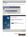
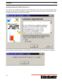
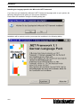
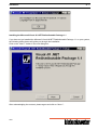
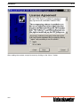
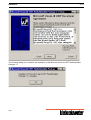
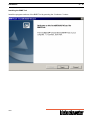
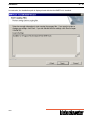
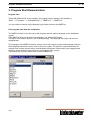
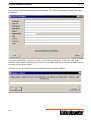
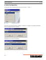
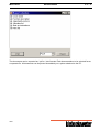
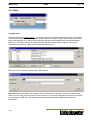
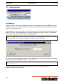
BMR-Tool Kieback&Peter GmbH & Co. KG Tempelhofer Weg 50 12347 Berlin/Germany Telefon: +49 30 60095-0, Telefax: +49 30 60095-164 www.kieback-peter.de, [email protected] A This user manual replaces all user manuals with a lower version number or older release date. This copy is not updated automatically. Subject to technical changes at any time. Kieback&Peter is not liable for damages that result directly or indirectly from the improper use of this document. Copyright © 2007 Kieback&Peter GmbH & Co KG Tempelhofer Weg 50 · D-12347 Berlin Telephone: +49 30 60095-0 . All rights reserved. No part of this book may be reproduced in any form (by printing, photocopying, or otherwise) or processed, copied, or distributed using electronic systems without written permission from Kieback&Peter. A BMRTool BMRTool 1. General points 2. Installation 3. Program Start/Demonstration 4. Initial Configuration 5. Menu items 6. Macro configuration 7. Update 08/08 General points 1. - 2 1. General points General points The BMRTool is a program for the simple configuration of heating and ventilation plants. It works under the MS-Windows XP operating system. For whom is the BMRTool intended? The BMRTool is tailor-made for clients who want to configure heating and ventilation plants without a great outlay. No detailed knowledge of project planning or programming are required. The BMRTool is therefore suitable for e.g. heating and ventilation construction companies as well as for control cabinet builders. Properties The BMRTool has the following salient properties: Configuration tool for heating and ventilation plants Simple to use Self-explanatory tool without complicated manuals No project planning or programming knowledge required Quick and easy macro overview No rigid macros, high flexibility by the use of options Region and language selectable Assignment of the BMR or the BMF function modules takes place automatically Project planning can be sent quickly and simply to the BMR Including the documentation of the configuration, functional description, commissioning instructions, assignment and parts list Email transmission of the order list from the BMRTool 08/08 General points 1. - 3 1. General points .............................................................................................................................. 2 08/08 Installation 2. - 4 2. Installation After the installation CD has been inserted, the BMRTool can be started by calling the "Setup.exe" file. The language for the setup then has to be selected. The preparation for the installation is now carried out and a search is made for components already installed. 08/08 Installation 2. - 5 Installing the Microsoft .NET Framework 1.1 If you have not yet installed the Microsoft .Net Framework on your system, the following dialog boxes will guide you through the installation of the Microsoft .NET Framework. Agree to the contents of the next dialog box and click on the “Install” button. After pressing the following button, the installation of the Microsoft .NET Framework is completed. 08/08 Installation Installing the language pack for the Microsoft .NET Framework If you have not yet installed the Microsoft .NET Framework language pack on your system, the following dialog boxes will guide you through the installation. Please start the installation using the following dialog box. Installation will be carried out after you accept the conditions in the following dialog. 08/08 2. - 6 Installation 2. - 7 Installing the Microsoft Visual J# .NET Redistributable Package 1.1 If you have not yet installed the Microsoft Visual J#.NET Redistributable Package 1.1 on your system, the following dialog boxes will guide you through the installation. Click on the “Next >” button in the next dialog box. After acknowledging the contract, please agree and click on “Next >”. 08/08 Installation After reading the contract, accept its terms by clicking on the “Next >” button. 08/08 2. - 8 Installation 2. - 9 The following dialog box completes the installation of the Microsoft Visual J# .NET Redistributable Package 1.1. 08/08 Installation Installing the BMR Tool Install the program sections of the BMR Tool by pressing the “Continue->” button. 08/08 2. - 10 Installation 2. - 11 Please enter your username and company in the following dialog. Then confirm by pressing the "Continue >" button. 08/08 Installation Please select "Complete" in the next dialog. 08/08 2. - 12 Installation In conclusion, the installation path is displayed and with that the BMRTool is installed. 08/08 2. - 13 Installation The BMRTool is ready for use after the system has been rebooted. 08/08 2. - 14 Installation 2. - 15 2. Installation .................................................................................................................................... 4 08/08 Program Start/Demonstration 3. - 16 3. Program Start/Demonstration Program start Taking MS Windows XP as an example, the program can be started in the taskbar by "Start" --> "Programs" --> "Kieback&Peter" --> "BMRTool" --> "BMRTool" . You can create a shortcut on the desktop to get quick access to the BMRTool. First program start after the installation The BMRTool starts on the first call of the program with the system language on the installation system. If the BMRTool does not know the set language, it is started with English. The region to be used is queried (see following dialog). The language and region can also be changed later. The language of the BMRTool and its macros can be set using the region and language selection. Each language can have a choice of more than one region. The choice of region determines for example how country-specific macro functionalities are applied. Please select your language and region to ensure that the macro functions correspond to your country. The settings will only take effect after a restart of BMRTool. 08/08 Program Start/Demonstration 3. - 17 Please fill out all contact information in the next dialog. The lines of text marked in "bold" here must be filled out. If you have purchased a license key, enter it in the following dialog box. If either the “OK” or the “Cancel” button (without license key) is pressed or an invalid license key is entered, the BMR Tool will be launched as a demo version. A license key can be entered anytime afterwards via the menu item "Setting". 08/08 Program Start/Demonstration 3. - 18 The BMRTool is now started. Demo version If no valid license key is entered, BMRTool is started as a demo version. The following can be done with the demo version: a complete configuration can be created a configuration cannot be saved no documentation can be exported or printed no configuration can be sent to the BMR no order can be sent, exported or printed – – – – – 08/08 Program Start/Demonstration 3. - 19 3. Program Start/Demonstration ................................................................................................... 16 08/08 Initial Configuration 4. - 20 4. Initial Configuration A new project can be created using the menu item "Project" --> "New...". A selection of the plant type follows. Heating or ventilation, for example. The following illustrations refer to a heating project as an example. Templates can be selected if necessary. 08/08 Initial Configuration 4. - 21 In the following dialog, it is possible to a assign a project name. This is also reflected in the documentation. The project name can also be changed/adapted at a later time. The configuration can begin once the project name has been entered. There are basically two ways of doing this. 1. Selection of the desired sub-system from the combo box. 08/08 Initial Configuration 4. - 22 Additional options can then be set. 2. Click on the question-mark button. A selection appears of all sub-macros available in this macro. A description is displayed for each sub-macro. 08/08 Initial Configuration 4. - 23 After selecting all desired partial macros and options, the number of bus module controllers (BMR) and expansion modules (FBU) needed for the configuration is displayed on the lower, right-hand side of the dialog box. If the number of available modules needed for the assignment of the current 08/08 Initial Configuration 4. - 24 configuration is too low, the message “Assignment not possible” is displayed. Here you can adjust the configuration so that an assignment is possible again. The configuration can now be sent to the BMR. For this, the menu item "Send BMR data" is called up in the "Configuration" menu. With this selection, the current configuration is sent to the Bus Module Controller (BMR) when an IP address is entered. In this, the program notes the last three IP addresses used so that these do not have to be entered each time. It is still possible to enter a password. It is only necessary to enter a password if the password of the BMR for user level 3 was changed and is no longer the same as the factory setting. The password entered in the dialog box is saved with the respective project. Note: When planning is sent to the BMR via the BMR Tool, the password for user level 3 is reset to factory setting. You must then change your password again in the BMR. 08/08 Initial Configuration 4. - 25 If the transmission of the configuration to the BMR is not possible and the following window appears, then the configured plant is too complex in its control and sequencing functions. This is also displayed on the lower, right hand corner of the dialog box. You also receive a message to this effect when saving the project. The project can, however, still be saved. You have, for example, configured one heating circuit too many. You can get more detailed information in: "Macro configuration --> available macros". Note: A prerequisite for sending the configuration to the BMR is that the computer on which the BMR Tool is installed, must be connected to the BMR with a network cable. A crossover cable should be used if the BMR is to be connected directly to the PC. A patch cable can be used otherwise. The PC and the BMR must be located on the same network. For example: Network mask for BMR and PC: 255.255.255.0 BMR IP address:192.168.1.1 PC IP address:192.168.1.2 In order to check the connection between a laptop and a BMR, for example, you enter the following at the MS DOS entry request (Start --> Run... --> cmd.exe): ping 192.168.1.1 This is the address to be employed for the BMR. (192.168.1.1 in the above example) A positive answer can look like this: 08/08 Initial Configuration 4. - 26 Ping is carried out for 192.168.1.1 with 32 Bytes of data: Response Response Response Response from from from from 192.168.1.1: 192.168.1.1: 192.168.1.1: 192.168.1.1: Bytes=32 Bytes=32 Bytes=32 Bytes=32 time<1ms time=1ms time=1ms time<1ms TTL=127 TTL=127 TTL=127 TTL=127 Ping statistics for 192.168.1.1: Packages: Sent = 4, Received = 4, Lost = 0 (0% loss), Approx. time in millisec.: Minimum = 0ms, Maximum = 1ms, Average = 0ms Other helpful commands in the MS DOS entry request: ipconfig ipconfig /all Ipconfig is a program to read network data - displays IP address, sub-network mask, standard gateway. Ipconfig/all displays additional information. 08/08 Initial Configuration 4. - 27 4. Initial Configuration ................................................................................................................... 20 08/08 Menu items 5. - 28 5. Menu items All menu items and their functions are shown below. 5. Menu items ................................................................................................................................. 28 5.1. Project ....................................................................................................................................... 29 5.2. Adjustment ............................................................................................................................... 31 5.3. Documentation ......................................................................................................................... 33 5.4. Order ......................................................................................................................................... 38 5.5. Communication ........................................................................................................................ 40 5.6. Info ............................................................................................................................................ 08/08 42 Menu items Project 5.1. - 29 5.1. Project New... A new project can be created using this menu item. Open... With this menu item, an already saved project is loaded. The loaded configuration can be edited further. Edit designation... The project designation can be adapted here afterwards. This is also seen in the documentation. Save... The project is saved via this menu item. All configuration settings are saved. 08/08 Menu items Project 5.1. - 30 Export BMR data With this menu item, a file is created that can be transferred to the BMR. The file has the extension *.bmr. Once this file is saved, it can be loaded later on into the BMR via the web access of the BMR. Exit The BMRTool program is ended. 08/08 Menu items Adjustment 5.2. - 31 5.2. Adjustment Contact information... The contact information is entered here. These data are taken as standard for the invoice and delivery address in any subsequent order. The lines of text marked in "bold" here must be filled out. Change region... The language of the BMRTool and its macros can be set using the region and language selection. Each language can have a choice of more than one region. The choice of region determines for example how country-specific macro functionalities are applied. Please select your language and region to ensure that the macro functions correspond to your country. The settings will only take effect after a restart of BMRTool. 08/08 Menu items Adjustment 5.2. - 32 Enter license key... If you have purchased a license key, enter it in the following dialog box. If either the “OK” or the “Cancel” button (without license key) is pressed or an invalid license key is entered, the BMR Tool will be launched as a demo version. 08/08 Menu items Documentation 5.3. - 33 5.3. Documentation Cover page A preview of the cover page can be looked at in this menu item. It can also be printed out separately. ATTENTION! The preview corresponds to a print preview on an A4 sheet in portrait format. Should a preview not be possible, please check whether a printer is defined as the standard printer on the computer and the page size is set up as A4 in portrait format. Setting protocol... The entire configuration is documented in this menu item. For example, which sub-macros with which options, which operating and control parameters are used. This document can be looked at in a preview. It can be exported as a *.pdf, *.doc, or *.txt document. The document can be printed immediately on a printer attached to the PC. The individual subsystems can be selected/deselected for export/printing. 08/08 Menu items Documentation 5.3. - 34 ATTENTION! The preview corresponds to a print preview on an A4 sheet in portrait format. Should a preview not be possible, please check whether a printer is defined as the standard printer on the computer and the page size is set up as A4 in portrait format. Function description... The functions of all sub-macros and the options used there are described. An example document looks like the following: 08/08 Menu items Documentation 5.3. - 35 This document can be looked at in a preview. It can be exported as a *.pdf, *.doc, or *.txt document. The document can be printed immediately on a printer attached to the PC. The individual subsystems can be selected/deselected for export/printing. See figure in Setting protocol... ATTENTION! The preview corresponds to a print preview on an A4 sheet in portrait format. Should a preview not be possible, please check whether a printer is defined as the standard printer on the computer and the page size is set up as A4 in portrait format. Commissioning instructions... The commissioning instructions describe the procedure for the first start of the BMR with its function modules. Also included are, e.g. the physical conditions and the software settings that have to be taken into account. 08/08 Menu items Documentation 5.3. - 36 This document can be looked at in a preview. It can be exported as a *.pdf, *.doc, or *.txt document. The document can be printed immediately on a printer attached to the PC. The individual subsystems can be selected/deselected for export/printing. See figure in Setting protocol... ATTENTION! The preview corresponds to a print preview on an A4 sheet in portrait format. Should a preview not be possible, please check whether a printer is defined as the standard printer on the computer and the page size is set up as A4 in portrait format. Parts list... The parts list contains all devices and their quantities resulting from the standard configuration. Subsequent changes to devices or their quantities (see menu Order) are not taken into account here. Particulars of the article numbers of valves must be made after the valves have been designed (e.g. with the valve design program from Kieback&Peter http://www.kieback-peter.de/) in the menu item Order. They are not a constituent element of the parts list. This document can be looked at in a preview. It can be exported as a *.pdf, *.doc, or *.txt document. The document can be printed immediately on a printer attached to the PC. ATTENTION! The preview corresponds to a print preview on an A4 sheet in portrait format. Should a preview not be possible, please check whether a printer is defined as the standard printer on the computer and the page size is set up as A4 in portrait format. Assignment lists... The assignment list contains the connection diagrams of the Bus Module Controller (BMR) and Function Module (BMF). All terminal assignments (terminal text, terminal designation, module) of the relevant configuration are listed. This document can be looked at in a preview. It can be exported as a *.pdf, *.doc, or *.txt document. The document can be printed immediately on a printer attached to the PC. The individual subsystems can be selected/deselected for export/printing. See figure in Setting protocol... ATTENTION! The preview corresponds to a print preview on an A4 sheet in portrait format. Should a preview not be possible, please check whether a printer is defined as the standard printer on the computer and the page size is set up as A4 in portrait format. Total documentation... With the help of the total documentation, all part documentations can be collected together, printed and exported. 08/08 Menu items Documentation 5.3. - 37 The documents can be exported as *.pdf or *.doc formats. Each documentation to be selected forms a separate file. All documents can be printed immediately on a printer attached to the PC. 08/08 Menu items Order 5.4. - 38 5.4. Order Compile order... With the menu item Compile order..., all devices and their quantities determined by the configuration are collected together. Particulars of the article numbers of valves must be entered after the valves have been designed (e.g. with the valve design program from Kieback&Peter http://www.kiebackpeter.de/). The article number is defined with the aid of the valve design program. This is then assigned to the valve by editing the corresponding order item. Each item can be edited by pressing the "Edit" button . New devices can be added, for example, from an offered list. If an article number is entered that does not come from the list (fold-out of the combo box), the article designation field can be released by pressing the "TAB" key. A designation can now be entered without editing the order item afterwards. 08/08 Menu items Order 5.4. - 39 Once the editing of the order list is completed, it can be displayed as a preview, printed, or output in the formats *.pdf, *.doc, *.txt, and *.csv. It is also possible to send an email to Kieback&Peter by pressing the "Send email" button. The email program installed on the PC is started by entering the name of the email recipient. All information such as recipient, sender (must have been entered in the contact information), subject, attachments and text of the email message are already present and can be adapted if necessary. The BMRTool is optimized for Microsoft Outlook. Contract conditions... The pdf-document that contain the Kieback&Peter contract conditions is displayed. 08/08 Menu items Communication 5.5. - 40 5.5. Communication Send BMR data With this selection, the current configuration is sent to the Bus Module Controller (BMR) when an IP address is entered. In this, the program notes the last three IP addresses used so that these do not have to be entered each time. It is still possible to enter a password. It is only necessary to enter a password if the password of the BMR for user level 3 was changed and is no longer the same as the factory setting. The password entered in the dialog box is saved with the respective project. Note: When planning is sent to the BMR via the BMR Tool, the password for user level 3 is reset to factory setting. You must then change your password again in the BMR. In order to check the connection between a laptop and a BMR, for example, you enter the following at the MS DOS entry request (Start --> Run... --> cmd.exe): ping 192.168.1.1 This is the address to be employed for the BMR. (192.168.1.1 in the above example) A positive answer can look like this: 08/08 Menu items Communication 5.5. - 41 Ping is carried out for 192.168.1.1 with 32 Bytes of data: Response Response Response Response from from from from 192.168.1.1: 192.168.1.1: 192.168.1.1: 192.168.1.1: Bytes=32 Bytes=32 Bytes=32 Bytes=32 time<1ms time=1ms time=1ms time<1ms TTL=127 TTL=127 TTL=127 TTL=127 Ping statistics for 192.168.1.1: Packages: Sent = 4, Received = 4, Lost = 0 (0% loss), Approx. time in millisec.: Minimum = 0ms, Maximum = 1ms, Average = 0ms Other helpful commands in the MS DOS entry request: ipconfig ipconfig /all Ipconfig is a program to read network data - displays IP address, sub-network mask, standard gateway. Ipconfig/all displays additional information. Send BMR data from file With this menu item , a project planning file that has been created via the menu item "Project" --> "Export BMR data" can be transferred to the BMR. Applicable here is the IP input as well as the instructions in the "Send BMR data" menu item. A data backup that has been compiled via the web browser access of the BMR, can also be sent again via this path to the BMR. 08/08 Menu items 5.6. Info General program information is displayed: – Location of the BMRTool start file – Installation path – BMRTool version – Data directory – Macro version 08/08 Info 5.6. - 42 Macro configuration 6. - 43 6. Macro configuration There is a variety of editing facilities available for each sub-macro. These are listed and explained afterwards. 6. Macro configuration .................................................................................................................. 43 6.1. Plant designation ..................................................................................................................... 44 6.2. Operating/Actual values .......................................................................................................... 45 6.3. Control parameters/Setpoints ................................................................................................. 46 6.4. Schedules ................................................................................................................................. 48 6.5. Copy sub-system ..................................................................................................................... 51 6.6. Module number limitation ....................................................................................................... 52 6.7. available macros ...................................................................................................................... 53 6.8. Text abbreviations ................................................................................................................... 08/08 55 Macro configuration Plant designation 6.1. - 44 6.1. Plant designation A sub-macro section designation (e.g. plant type "Heating") can be entered above each image. This is also transferred to the BMR in the plant type "Heating" and so forms the plant designation in the BMR. As the entire project in BMRTool is a plant for the "Ventilation", the designation for this plant type is not transferred to the BMR. 08/08 Macro configuration Operating/Actual values 6.2. - 45 6.2. Operating/Actual values With the aid of the "Operating" button... ... you get into the dialog for the editing of the operating parameters. These parameters are available to the users in the BMR interface from user level 0. Switching actions, such as switching on a pump, is possible in user level 1. The removal of the check mark for all parameters listed here leads to these parameters no longer being displayed in the user level 0. Each parameter can also be edited in terms of its text. 08/08 Macro configuration Control parameters/Setpoints 6.3. - 46 6.3. Control parameters/Setpoints With the aid of the "Control parameter" button... ... you get into the dialog for the editing of the control parameters. These parameters are available to the users in the BMR interface from user level 1. A change in value, for example a modification to the maximum supply temperature, is possible in user level 2. The removal of the check mark for all parameters listed here leads to these parameters no longer being displayed in user level 1 and it no longer being possible to change them in user level 2. Each parameter can also be edited in terms of its text and its value. 08/08 Macro configuration Schedules 6.4. - 47 6.4. Schedules With the aid of the "Schedules" button... ... you get into the dialog for the editing of the schedules. You can address and adjust all schedules in the project by means of the combo box. The selection of a macro is not necessary for this. In the overview, blue means "Night" status, gray means "Off" and orange means the status "On" or "Day". After selecting a day and then clicking on the "Edit" button, you get to the editing dialog of the times. Here switch statuses can be added, edited, and deleted. 08/08 Macro configuration Schedules 6.4. - 48 A new switch status can for example be produced by the following dialog. If you click on the "Copy day" button in the overview dialog, you get the following window. This allows you to copy the time statuses of the already selected day to several other days. 08/08 Macro configuration Schedules 6.4. - 49 If you click on the "Copy schedule" button in the overview dialog, you get the following window. This allows you to copy the entire schedule to one or more schedules that may be in the project. 08/08 Macro configuration Copy sub-system 6.5. - 50 6.5. Copy sub-system With the aid of the "Copy sub-system" button... ... you get into the dialog for the copying of the entire sub-system (macro). Here you select the macro to which the previously marked macro is to be copied. All settings (for example, operating and control parameters) are copied over as well. 08/08 Macro configuration Module number limitation 6.6. - 51 6.6. Module number limitation After selecting all desired partial macros and options, the number of bus module controllers (BMR) and expansion modules (FBU) needed for the configuration is displayed on the lower, right-hand side of the dialog box. If the number of available modules needed for the assignment of the current configuration is too low, the message “Assignment not possible” is displayed. Here you can adjust the configuration so that an assignment is possible again. 08/08 Macro configuration available macros 6.7. - 52 6.7. available macros Plant combinations in the following table are examples for the heating type of plant. Option District heating or single tank system 1. Heating circuit 2. Heating circuit 3. Heating circuit 1 Only single tank system x x x 2 x x x 3 x x 4 x (without ret. flow bypass with single tank system) x 5 x (without ret. flow bypass with single tank system) x 6 x (without ret. flow bypass with single tank system) 1. Mod. W.Ht. or simple W.Ht. (incl. solar) 2. Mod. W.Ht. or simple W.Ht. (incl. solar) x (without controlled circulation pump with mod. W.Ht.) x x 7 x x 8 x x 9 x x x x x (without controlled circulation pump with mod. W.Ht.) x x x x x (without controlled circulation pump with mod. W.Ht.) x x If the transmission of the configuration to the BMR is not possible and the following window appears, then the configured plant is too complex in its control and sequencing functions. 08/08 Macro configuration available macros 6.7. - 53 This is also displayed on the lower, right hand corner of the dialog box. You also receive a message to this effect when saving the project. The project can, however, still be saved. You have, for example, configured one heating circuit too many. If the configuration cannot be transmitted to the BMR for the above reasons, the configuration must be changed. Example: A configuration of a district heating macro with 3 heating circuits cannot be sent to the BMR. Adaptation by changing 2 heating circuits. 08/08 Macro configuration Text abbreviations 6.8. Text abbreviations Text abbreviations Meaning SC Switch command (output signal of digital values) YB Actuator command (output signal of analog values) AL Malfunction message OM Operating message Op.h. Operating hours AU Outside air CLOSED Supply air EXA Exhaust air FO Outgoing air MM Servicing message HR Heat recovery ACM Airstream monitoring Grp.al.FD Fire protection flap RH Auxiliary heater FC Frequency converter 08/08 6.8. - 54 Update 7. - 55 7. Update If a new version of the BMR Tool or of the macros is available, you can install them by opening the “Setup.exe” file, just like during the first installation. The installation dialog boxes differ according to the update packages to be carried out. 7. Update ......................................................................................................................................... 56 7.1. New BMR Tool .......................................................................................................................... 57 7.2. New macros .............................................................................................................................. 60 08/08 Update New BMR Tool 7.1. - 56 7.1. New BMR Tool If a new BMR Tool version is available, follow the following dialog boxes through the update. If the new BMR Tool version also comes with new macros, these will be automatically updated. 08/08 Update 08/08 New BMR Tool 7.1. - 57 Update 08/08 New BMR Tool 7.1. - 58 Update New macros 7.2. New macros If new macros are available, follow the following dialogs through the update. After selecting the language, please activate the “Change program” option. Leave the selected features in the following dialog box as they are and confirm by clicking on “Continue”. 08/08 7.2. - 59 Update 08/08 New macros 7.2. - 60 Update 08/08 New macros 7.2. - 61