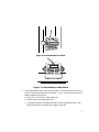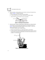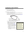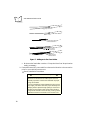
1
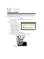
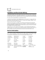
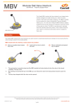
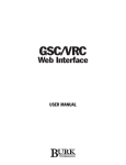
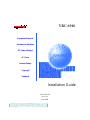
VRC 6940 Equipment Required Hardware Installation DC Power (Battery) AC Power Internal Battery Copyright Feedback Installation Guide 72E-41229-02 Revision A May 2000 VRC 6940 Installation Guide 72E-41229-02 Revision A May 2000 2000 by Symbol Technologies, Inc. All rights reserved. No part of this publication may be reproduced or used in any form, or by any electrical or mechanical means, without permission in writing from Symbol. This includes electronic or mechanical means, such as photocopying, recording, or information storage and retrieval systems. The material in this manual is subject to change without notice. The software is provided strictly on an “as is” basis. All software, including firmware, furnished to the user is on a licensed basis. Symbol grants to the user a non-transferable and non-exclusive license to use each software or firmware program delivered hereunder (licensed program). Except as noted below, such license may not be assigned, sublicensed, or otherwise transferred by the user without prior written consent of Symbol. No right to copy a licensed program in whole or in part is granted, except as permitted under copyright law. The user shall not modify, merge, or incorporate any form or portion of a licensed program with other program material, create a derivative work from a licensed program, or use a licensed program in a network without written permission from Symbol. The user agrees to maintain Symbol’s copyright notice on the licensed programs delivered hereunder, and to include the same on any authorized copies it makes, in whole or in part. The user agrees not to decompile, disassemble, decode, or reverse engineer any licensed program delivered to the user or any portion thereof. Symbol reserves the right to make changes to any software or product to improve reliability, function, or design. Symbol does not assume any product liability arising out of, or in connection with, the application or use of any product, circuit, or application described herein. No license is granted, either expressly or by implication, estoppel, or otherwise under any Symbol Technologies, Inc., intellectual property rights. An implied license only exists for equipment, circuits, and subsystems contained in Symbol products. Symbol, Spectrum One, and Spectrum24 are registered trademarks of Symbol Technologies, Inc. Other product names mentioned in this manual may be trademarks or registered trademarks of their respective companies and are hereby acknowledged. Symbol Technologies, Inc. One Symbol Plaza Holtsville, New York 11742-1300 http://www.symbol.com 4 Installing a VRC 6940 Terminal This manual describes how to install a VRC 6940 terminal into a vehicle or onto a wall or workbench. Please read all of these instructions before you begin. Caution A properly trained technician must perform the installation. Improper installation can damage your vehicle. Equipment Required Vehicle Mounted VRC 6940 ! ! ! ! ! ! an External DC power cable (supplied with terminal). minimum of two 3/8” bolts with self-locking nylon nuts. a drill with a 7/16” drill bit. 7/16” hex wrench. a connector for terminating the External DC power cable. Select one that mates with your vehicle’s power supply. primary or external antenna (optional). Wall or Workbench Mounted VRC 6940 ! ! ! ! ! ! ! AC universal power supply (Symbol p/n 50-14001-006) AC line cable (Symbol p/n 23844-00-00) DC power cable (Symbol p/n 25-39385-01) minimum of two 3/8” bolts with self-locking nylon nuts a drill with a 7/16” drill bit 7/16” hex wrench primary or external antenna (optional) 5 VRC 6940 Installation Guide Hardware Installation The physical requirements of the work area affect where you place the terminal. There are different installation options, depending on where you plan to locate it. Figure 1 shows a terminal mounted on a vehicle. Figure 2 shows a terminal mounted on a wall, and Figure 3 shows a terminal mounted on a workbench. Caution Do not install a VRC 6940 terminal in a location that will affect vehicle safety or driveability. To install VRC 6940 hardware: 1. Prepare a mounting location: Installation Note: Mounting Locations The bracket and terminal must be: • firmly secured to a surface that can support the terminal’s weight — on a vehicle, wall or workbench • secured with a minimum of two 3/8” diameter bolts and nylon self-locking nuts • easy to for end-users to see and reach a. Select a location to mount the terminal. The terminal’s attached bracket has holes cut for bolts. Use these holes to mark bolt hole locations. b. Prepare the mounting surface to accept two 3/8” bolts. Drill two holes with a 7/16” drill bit. 2. Install the terminal onto the mounting surface: a. Position the terminal on the mounting surface. b. Fasten it securely using a minimum of two 3/8” self-locking nuts. Figure 1. Terminal Mounted on a Vehicle 6 Figure 2. Terminal Mounted on a Wall F1 F2 F3 F4 F5 A B C D E F G 7 8 9 H I J K L M N 4 5 6 CLEAR O P Q R S T U 1 2 3 ENTER V W X Y Z SHIFT FUNC - 0 . BACK ON/OFF CTRL Figure 3. Terminal Mounted on a Workbench 3. Attach the Bracket Knobs. When you first unpack it, the terminal has hex bolts in place of the Bracket Knobs shown in Figures 1, 2, and 3. These knobs allow users to adjust the angle of the terminal. a. Use a 7/16” hex wrench to remove the bolts. b. Replace them with the Bracket Knobs. c. To adjust the angle of the display, partially unscrew the Bracket Knobs. Then adjust the angle of the terminal and re-tighten the knobs. 7 VRC 6940 Installation Guide 4. Optional: attach a primary antenna to the connector at the top of the terminal, as shown in Figure 4. To attach the antenna: a. Place the metal end of the antenna onto the connector. b. Line up the posts with the connector openings and press down gently. c. Twist the bottom ring clockwise to lock it into position. Back of Terminal Antenna Connector Figure 4. Attaching a Primary Antenna 5. Optional: install a vehicle-mounted antenna. Sometimes you can improve wireless communication by mounting an external antenna onto the vehicle, as shown in Figure 5. Symbol has several different external antennas available. Contact your Support Representative for more information. To connect an external vehicle-mounted antenna: a. Secure the external antenna to an appropriate location on the vehicle. b. Connect one end of a coaxial cable to the terminal’s Antenna Connector. Connect the other end to the vehicle-mounted antenna. Make the coaxial cable as short as possible to minimize signal loss. Antenna Coaxial Cable Figure 5. Vehicle-Mounted Antenna 8 Providing Power: Vehicle Installations VRC 6940 terminals can be powered by: ! 12V or 24V gas-powered vehicles ! battery-powered vehicles, up to 60 volts To provide power to a vehicle-installed VRC 6940: 1. Locate your vehicle’s power source. Always connect a VRC 6940 terminal to a continuous or unswitched power source. 2. Prepare the External DC power cable. One end of the power cable fits into the terminal’s DC Power connector. The other end has no connector (see Figure 6). Plug in to the DC Power connector on the terminal Cable End to be prepared Figure 6. Preparing the External DC Power Cable To prepare the end of the External DC power cable: a. In-line fuse holder: if no fused output is available, add a fuse-holder and 5 Amp fuse to the External DC power cable. Follow these steps and refer to Figure 7: i. Strip back six inches of the cable jacket. ii. Cut about 5” from the red power wire and strip 3/8” insulation from the wire. iii. Strip 3/8” insulation from the fuseholder wire. iv. Twist the stripped wire ends together and splice them using a twist-on nylon wire connector. Installation Note: Power Sources The ideal location for connecting a VRC 6940 External DC power cable would be a fused power source on the vehicle’s power distribution panel. If no fused power source is available, connect the terminal directly to a vehicle battery. In this case, Symbol recommends you use an in-line fuse holder and 5A slow-blow fuse. The fuse protects your vehicle from an electrical short on the power cable. 9 VRC 6940 Installation Guide Red power wire i. ii. In-line fuse holder with 5A slow-blow fuse Twist-on nylon wire connector iii. iv. v. Wrapped wires and fuse holder Figure 7. Adding an In-line Fuse Holder v. Make sure the fuse holder contains a 5 Amp slow-blow fuse. Wrap the wires neatly, as necessary. b. Route the External DC power cable from the terminal location to the connection point for your vehicle’s power source. See the Installation Note below. ! Installation Note: Cable Routing Caution ! The means of routing and securing the External DC power cable from the terminal to the vehicle power source is extremely important. Hazards associated with improper wiring can be severe. To avoid unintentional contact between the wire and any sharp edges, provide the cable with proper bushings and clamping where it passes through openings. If the wire is subjected to sharp surfaces and excess engine vibration, wiring harness insulation can wear away, causing a short between the bare wire and chassis. This can start a fire. 10 c. Prepare the cable termination: Strip Installation Note: Cable Termination 3/8” of insulation from the two wire How the cable terminates depends on ends and terminate them with a your vehicle. If your vehicle has a power connector that matches your vehicle’s output connector, then attach a mating requirements. See the Installation connector to the end of the power cable. Note, right, for more information. You may be able to connect to a fuse d. Connect the red wire to the vehicle panel with a commercially available power source. Connect the black wire connector. If your vehicle has no power to a vehicle ground wire or chassis output connector, attach a ring terminal (for a battery post) or blade terminal ground. connector (for a fuse panel). e. Connect the External DC power cable Consult your vehicle Owner’s Manual to your vehicle power source. for information on how to access your 3. Insert the terminal end of the External vehicle’s power supply. DC power cable into the terminal’s Power Connector. Align the red dot on the end of the power cable with the red dot on the Power Connector. WARNING A Lead Acid battery can leak Hydrogen gas. A spark anywhere near the battery can cause it to explode. Always make your final connection to power as far away from the battery as possible, i.e., connect the power cable to the battery first, then connect it to the terminal. Providing Power: Wall or Workbench Installations For wall or workbench-mounted terminals, or for operating a terminal while away from a vehicle, you can power an VRC 6940 from an AC universal power supply. You need the AC universal power supply, an AC line cable, and a DC power cable as listed on page 5. To provide power from an AC source: 1. Insert the AC line cable into the AC connector on the AC universal power supply. 2. Plug the other end of the AC line cable into an AC wall outlet. 3. Insert the DC power cable into the DC connector on the AC universal power supply. 4. Plug the other end of the cable into the terminal’s Power Connector. 11 VRC 6940 Installation Guide Installation and the Internal Battery A VRC 6940 terminal has an internal battery that powers the terminal if there is a temporary interruption, disconnection, or fluctuation in the main DC or AC power. We recommend that you save all data and close all applications before removing a terminal’s main power supply. You cannot use the internal battery to operate the terminal. A terminal’s internal battery may be depleted when you first install it. It charges itself from the terminal’s main power supply (DC or AC). If the main power supply is stable, you can plug in the terminal and use it immediately. If the main power supply is not stable, there may be power interruptions that cause the terminal to reset itself during its first few hours of operation. If the terminal resets itself, you may lose unsaved data. To avoid this, we recommend that you plug in the terminal and allow it to charge for two hours before using it. It takes 48 hours to fully charge the internal battery. A fully charged internal battery can maintain data for up to 72 hours if the unit is disconnected from its main power source. This time is reduced if the radio mode maintains continuous communication with a host. Service Information The unit must be correctly installed before you try to use it. If you have a problem running a unit or using your equipment, contact Technical or Systems Support at your facility. If there is a problem with the equipment, they will contact the Symbol Support Center: United States 1-800-653-5350 Canada 905-629-7226 United Kingdom 0800 328 2424 Asia/Pacific 337-6588 Australia 1-800-672-906 Austria 1-505-5794 Denmark 7020-1718 Finland 9 5407 580 France 01-40-96-52-21 Germany 6074-49020 Italy 2-484441 Mexico 5-520-1835 Netherlands 315-271700 Norway 66810600 South Africa 11-4405668 Spain 9-1-320-39-09 Latin America Sales 1-800-347-0178 Inside US Europe/Mid-East Support +1-561-483-1275 Outside US Distributor Operations Sweden 84452900 12 Contact local distributor or call +44 118 945 7360 Warranty Symbol Technologies, Inc. (“Symbol”) manufactures its hardware products in accordance with industry-standard practices. Symbol warrants that for a period of twelve (12) months from date of shipment, products will be free from defects in materials and workmanship. This warranty is provided to the original owner only and is not transferable to any third party. It shall not apply to any product (i) which has been repaired or altered unless done or approved by Symbol, (ii) which has not been maintained in accordance with any operating or handling instructions supplied by Symbol, (iii) which has been subjected to unusual physical or electrical stress, misuse, abuse, power shortage, negligence or accident or (iv) which has been used other than in accordance with the product operating and handling instructions. Preventive maintenance is the responsibility of customer and is not covered under this warranty. Wear items and accessories having a Symbol serial number, will carry a 90-day limited warranty. Non-serialized items will carry a 30-day limited warranty. Warranty Coverage and Procedure During the warranty period, Symbol will repair or replace defective products returned to Symbol’s manufacturing plan in the US. For warranty service in North America, call the Symbol Support Center at 1-800-653-5350. International customers should contact the local Symbol office or support center. If warranty service is required, Symbol will issue a Return Material Authorization Number. Products must be shipped in the original or comparable packaging, shipping and insurance charges prepaid. Symbol will ship the repaired or replacement product freight and insurance prepaid in North America. Shipments from the US or other locations will be made F.O.B. Symbol’s manufacturing plant. Symbol will use new or refurbished parts at its discretion and will own all parts removed from repaired products. Customer will pay for the replacement product in case it does not return the replaced product to Symbol within 3 days of receipt of the replacement product. The process for return and customer’s charges will be in accordance with Symbol’s Exchange Policy in effect at the time of the exchange. Customer accepts full responsibility for its software and data including the appropriate backup thereof. Repair or replacement of a product during warranty will not extend the original warranty term. Symbol’s Customer Service organization offers an array of service plans, such as on-site, depot, or phone support, that can be implemented to meet customer’s special operational requirements and are available at a substantial discount during warranty period. General Except for the warranties stated above, Symbol disclaims all warranties, express or implied, on products furnished hereunder, including without limitation implied warranties of merchantability and fitness for a particular purpose. The stated express warranties are in lieu of all obligations or liabilities on part of Symbol for damages, including without limitation, special, indirect, or consequential damages arising out of or in connection with the use or performance of the product. Seller’s liability for damages to buyer or others resulting from the use of any product, shall in no way exceed the purchase price of said product, except in instances of injury to persons or property. Some states (or jurisdictions) do not allow the exclusion or limitation of incidental or consequential damages, so the proceeding exclusion or limitation may not apply to you. 13 VRC 6940 Installation Guide Regulatory Information Radio Frequency Interference Requirements This device has been tested and found to comply with the limits for a Class A digital device pursuant to Part 15 of the Federal Communications Commissions Rules and Regulation. These limits are designed to provide reasonable protection against harmful interference when the equipment is operated in a commercial environment. This equipment generates, uses, and can radiate radio frequency energy and, if not installed and used in accordance with the instruction manual, may cause harmful interference to radio communications. Operation of this equipment in a residential area is likely to cause harmful interference in which case the user will be required to correct the interference at his own expense. However, there is no guarantee that interference will not occur in a particular installation. If the equipment does cause harmful interference to radio or television reception, which can be determined by turning the equipment off and on, the user is encouraged to try to correct the interference by one or more of the following measures: • Re-orient or relocate the receiving antenna. • Increase the separation between the equipment and receiver. • Connect the equipment into an outlet on a circuit different from that which the receiver is connected. • Consult the dealer or an experienced radio/TV technician for help. Radio Frequency Interference Requirements - Canada This Class B digital apparatus complies with Industry Canada Standard ICES-003. Cet appareil numérique de la classe B est conform à la norme NMB-003 d’Industrie Canada. CE Marking and European Union Compliance Products intended for sale within the European Union are marked with the CE Mark which indicates compliance to applicable Directives and European Normes (EN), as follows. Amendments to these Directives or ENs are included: Applicable Directives • Electromagnetic Compatibility Directive 89/336/EEC • Low Voltage Directive 73/23/EEC Applicable Standards • EN 60 950 + A1 + A2 +A3 + A4 + A11- Safety of Information Technology Equipment Including Electrical Business Equipment • EN 55022:1998, Limits and Methods of Measurement of Radio Disturbance Characteristics of Information Technology Equipment • EN 55024:1998; Information technology equipment-Immunity characteristics-Limits and methods of measurement • IEC 1000-4-2:1995; Electromagnetic compatibility (EMC); Part 4: Testing and measurement techniques; Section 4.2: Electrostatic discharge immunity test • IEC 1000-4-3: 1997, Electromagnetic Compatibility (EMC); Part 4 Testing and measurement techniques; Section 3. Radiated, radio frequency, electromagnetic field immunity test • IEC 1000-4-4:1995, Electromagnetic compatibility (EMC); Part 4: Testing and measurement techniques; Sec- 14 tion 4: Testing electrical fast transient,/Burst Immunity • IEC 1000-4-5:1995, Electromagnetic compatibility (EMC), Part 4: Testing and measurement techniques; Section 5: Surge Immunity • IEC 1000-4-6:1996 Electromagnetic compatibility (EMC), Part 4: Testing and measurement techniques; Section 6: Immunity to conducted disturbances, induced by radio frequency fields • IEC 1000-4-11:1994 Electromagnetic compatibility (EMC), Part 4: Testing and measurement techniques; Section 11: Voltage Dips, Short Interruptions and Voltage Variations RF Devices Symbol’s RF products are designed to be compliant with the rules and regulations in the locations into which they are sold and will be labeled as required. The majority of Symbol’s RF devices are type approved and do not require the user to obtain license or authorization before using the equipment. Any changes or modifications to Symbol Technologies equipment not expressly approved by Symbol Technologies could void the user’s authority to operate the equipment. Power Cable To ensure compliance with the European Directive 89/336/CEE, the terminal must be used with a power cable less than 3 meters in length. Do not extend the length of the supplied power cable. 15 VRC 6940 Installation Guide 16 Tell Us What You Think... We’d like to know what you think about this Manual. Please take a moment to fill out this questionaire and fax this form to: (516) 738-3318, or mail to: Symbol Technologies, Inc. One Symbol Plaza M/S B-4 Holtsville, NY 11742-1300 Attn: Technical Publications Manager IMPORTANT: If you need product support, please call the appropriate customer support number provided. Unfortunately, we cannot provide customer support at the fax number above. User’s Manual Title: _______________________________________________ (please include revision level) How familiar were you with this product before using this manual? Very familiar Slightly familiar Not at all familiar Did this manual meet your needs? If not, please explain. ________________ ________________________________________________________________ What topics need to be added to the index, if applicable? _______________ ________________________________________________________________ What topics do you feel need to be better discussed? Please be specific. _________________________________________________________________ What can we do to further improve our manuals?_______________________ _________________________________________________________________ _________________________________________________________________ Thank you for your input—We value your comments. VRC 6940 Installation Guide 72E-41229-02 Revision A — May 2000 Symbol Technologies, Inc. One Symbol Plaza, Holtsville N.Y. 11742