1
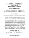
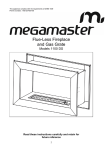
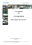
SS SERIES SMART CONSOLE USER MANUAL V1.0 JUNE 2015 INTRODUCTION Welcome to choose Automatic Tank Gauging (ATGs) System of Windbell Company. You are strongly recommended to read this manual before installation. The installation and maintenance for the products must be done by the qualified technicians. Safety instruction The ATGs system is installed in gas station and oil depot, please read safety instructions for explosion protection. Power must not be switched on before installation & maintenance. The products are prohibited to be installed in explosion proof area over its own Ex-proof grade. The console and printer must be installed in safe area, such as office. Safety warning The tank must have earth busbar; the earth must be safe and reliable. ATGs system must share the same ground with tank. Unpack and check Please check all the materials according to the list. If anything missed, please contact the local representative or distributor directly. You can also find the contact information of Windbell in this manual. Quality Track Card After installation, please post the Quality Track Card to Service Department of Windbell for accurate and timely service. Thank you very much! CONTENT 1. Summary--------------------------------------------------------------------------------------------1 1.1 System summary-----------------------------------------------------------------------------1 1.2 Console structure----------------------------------------------------------------------------1 1.3 Features and Technical parameters-------------------------------------------------------2 2. Installation ----------------------------------------------------------------------------------------3 2.1 Installation------------------------------------------------------------------------------------3 2.2 Electric wiring diagram of ATGs system-------------------------------------------------4 2.3 Connection between console and software----------------------------------------------5 2.4 Installation accessories--------------------------------------------------------------------5 3. Operation-----------------------------------------------------------------------------------------6 3.1 Release alarm--------------------------------------------------------------------------------7 3.2 Printer-----------------------------------------------------------------------------------------7 3.3 System setup---------------------------------------------------------------------------------7 3.4 Shift-------------------------------------------------------------------------------------------7 3.5 Next page------------------------------------------------------------------------------------7 3.6 Reports--------------------------------------------------------------------------------------7 3.7 Leak sensor--------------------------------------------------------------------------------7 4. System setup------------------------------------------------------------------------------------8 4.1 System configure screen-----------------------------------------------------------------8 4.2 Petrol station info configure-------------------------------------------------------------8 4.3 Oil type configure-------------------------------------------------------------------------9 4.4 Tank configure-----------------------------------------------------------------------------9 4.5 Probe configure ---------------------------------------------------------------------------10 4.6 Tank table configure----------------------------------------------------------------------11 4.7 Probe test-----------------------------------------------------------------------------------12 4.8 User configure-----------------------------------------------------------------------------12 4.9 Interface------------------------------------------------------------------------------------13 4.10 Program update --------------------------------------------------------------------------13 4.11 System maintenance---------------------------------------------------------------------14 4.12 Time configure --------------------------------------------------------------------------15 4.13 Leak sensor configure-------------------------------------------------------------------15 4.14 GSM configure---------------------------------------------------------------------------15 4.15 Density configure------------------------------------------------------------------------16 4.16Beep level configure---------------------------------------------------------------------17 5. Reports------------------------------------------------------------------------------------------17 5.1 Alarm report--------------------------------------------------------------------------------17 5.2 Delivery report------------------------------------------------------------------------------18 5.3 Shift report----------------------------------------------------------------------------------18 5.4 Inventory report----------------------------------------------------------------------------18 5.5 Leak detection report----------------------------------------------------------------------19 5.6 System Log---------------------------------------------------------------------------------19 5.7 SMS report---------------------------------------------------------------------------------19 1. Summary 1.1 System summary This automatic tank gauging system is mainly consists of smart console and magnetostrictive probe. It monitoring oil product level, water level, temperature in real time, and display inventory data, alarm information and leak detection information, and automatically generate history report for inquiry in future. International graphic touch screen and user-friendly icon, makes it is easy for new user. 1.2 System structure Smart console (please see below) is a powerful operation platform, the data processing and record center, communicate with probe by RS485, and also offer safety and reliable power to probe. It consists of TFT colorful touch screen, advanced process CPU, safety barriers and power module. Display and operating screen is 8’’ size, 800*600 resolutions. The CPU which composed of the embedded processor and peripheral circuit is the control center of the whole tank gauges system. The safety barrier is intrinsic safe parts, offer safety power to probe. SS160Plus Smart Console 1 SS160Plus Smart Console User Manual 1.3 Features and Technical parameters System feature International graphic touch screen Real time monitoring oil product level, water level, density, volume and temperature Monitor up to 12 tank at one compact unit (Standard monitor up to 6 tanks) Automatic alarm and release alarm Automatic generate delivery report, inventory report, alarm report and leak detection report Automatically generate tank volume chart Support TCP/IP Support programmable leak detection test PLD Support external GSM message module ( Option) Support import & export tank volume chart, very convenient Security password for authorization Language optional among English (default), Spanish, Portuguese Support connect to Submersible Pump Console SS160-EM02 Open communication protocol, can be connected with the central control system of mainstream fuel dispensers, totally satisfy management demand of oil retail companies Technical parameters Power: AC220V, 0.2A, 50/60HZ Working temperature: -20 to 60 ℃ Install location: Safety place Display resolution: 800x600 Safety barrier: WB GSB03 Display size: 8’’ full color LCD Explosion proof grade: [Ex ia Ga] II A 2 RS232 communication serial ports: connects Dimension: 5.7x11.8x9.0 Inches connects to probe Replay output: 2 groups. Node capacity AC250V/3A, DC30V/3A to printer, computer, Modem or GSM module 1 RS485 communication serial port: 1 USB port for program upgrade 145x300x230 mm 2 Weight: 11 kgs SS160Plus Smart Console User Manual 2. Installation 2.1 Installation of smart console ① Look for convenient place on the wall in office, to install smart console. ② Install the fixed plate of console tightly on the wall by expansion screw ③ Hang console on the fixed plate reliably ④ The PE of console should be connected to earth reliably with more than 6 mm² multi-core copper soft cables ⑤ Power supply AC220V Safety warning Console, printer must be installed in Non-Hazardous zone! Installation dimension drawing of console (Unit: mm) 3 SS160Plus Smart Console User Manual 2.2 Electrical wiring diagram of ATG system The cable from probe must be correctly coupled into relevant safety barrier inside console. The shielding of cable must be coupled into PE of safety barrier. The safety barrier also must be coupled into earth reliably. As fig. below. Cable connection table No. Power wires Port of safety barrier ① Blue wire Power (Power +) ② Brown wire 485A ③ White wire 485B ④ Black wire GND (Power-) ⑤ Shielded wire Safety warning Earth terminal of safety barrier should be connected to ground reliably by more than 6 mm² multi-core copper cable. Forbid turning on power for the system before correct couple with cables. ATGs system must share the same earth with tank. 4 SS160Plus Smart Console User Manual 2.3 Connection between console and PC software When console need to be connected with PC management system and printer, please take PC line and printer lines) which both RS232 serial lines) from console packing box, couple them into relevant port. Along with console, we prepare two RS232 cables for communication, one for site computer, another one for external printer. Safety warning Please carefully check every part whether it is ok after installation. After confirmed Ok, power on system. 2.4 Installation accessories Name 5 Qty Power cable 1 Communication cable RS232 2 Fixed plate 1 Expansion bolt 4 PG9 6 Spare fuse 1 keys 2 Spare Battery 1 SS160Plus Smart Console User Manual 3. Operation Monitoring screen (Home page) This monitor screen will be automatically shown, after power on. ① If initialized operation, the tank information is blank, please click “Setup” button to set up ② System (detail operation please see relevant introduction) If need inquire detail information of each tank, please directly click the graphic of tank. If there no operation on screen for about 5 minutes, console will automatically enter into screen saver state, black screen but program working from time to time. The screen will light again if touched. 6 SS160Plus Smart Console User Manual 3.1 Release alarm When alarm beep, for example, Water high (W H), Product low low(P LL), Product low (P L), Product high (P H), Product high high (P HH), Temperature high (T H), Temperature low (T L), click this to release alarm, then beep stop. 3.2 Printer Click this button at homepage, will print the current data of available tanks 3.3 Setup When need to set up system information or amend configuration, please click this button. 3.4 Shift Click this button when shift, there will show a dialog box “Shift Confirm”, choose” Yes” to confirm shift, system will create a shift report automatically. 3.5 Next (Next page) There are 4 tanks information displayed on screen, if inquire tanks information more than 4, like tank 5 an 6, just click this button to view. 3.6 Reports When need to inquire reports information, click this button to enter into report page, and choose relevant report to see detail data. 3.7 Leak sensor When need to inquire if any leakage of tank, click this button to see leak detection screen. 7 SS160Plus Smart Console User Manual 4. System Setup 1.1 System configure Click at monitor screen, enter into “System configure” screen. Station – set the info of petrol station Oil – set the information of oil type Tank – set tanks information Probe – set probe ID Tank table – input tank volume Probe test – test the comm. between Probe and console. User – set user name and password Interface – set interface parameter Update – upgrade console program Maintain – maintenance console program Time – set console clock Leak - set leak detection information GSM – set GSM configuration Density – set density measurement information Beep – set beep alarm information 4.2 Station configure Click to enter into petrol station configure screen Introduction Input company code Input petrol station serial code Input petrol station name Click “Save” to save above information Note: the company code and petrol station serial code are used for transmit data to head-office software 8 SS160Plus Smart Console User Manual 4.3 Oil configure Click to set oil product type and expansion rate. Introduction Click to choose oil name Click to input expansion factor Click “Save” to save above information 4.4 Tank configure Click to set up tank number, height and maximum capacity Introduction Choose “Valid” or “Invalid” at status, to confirm the tank selected if valid or not Choose right oil type Choose the tank’s serial number in petrol station Choose color to distinguish different oil type Input tank height 9 SS160Plus Smart Console User Manual Choose “Yes” or “No” to start or stop automatic leak detection function Input maximum capacity of tank Choose desired duration of leak detection test Choose leak detection test grade Input the starting time of automatic leak detection test Choose “Included” or not at Water Flag which mean cross volume include water or not. Please do not forget to click save after setup. When you want to delete one tank, firstly click tank at left table, and then click “Delete” 4.5 Probe configure Click to set probe ID, alarm values and oil offset, water offset. Introduction Input tank serial number, please refer to the tank configure Input relevant alarm values at O HH, O H, O LL, O L, Temp H, Temp L, W H, W HH OHH alarm indicates that the oil product is likely to overfill, stop filling right now. OH alarm indicates that the oil product already arrive the first alarm, keep your eyes on filling. OL alarm indicates that the fuel storage inside tank is not enough, please make purchase order OLL alarm indicates that there not fuel inside the tank, please close the business of this tank W HH alarm indicates to the manager of petrol station make plan to remove the water out of tank Input probe ID, please ensure the right ID, each probe have sole ID which same as the manufacturing code on probe nameplate, please record before install. If need to calibrate oil level and water level, please measure the oil level and water level by dip stick, input the measured value in O value and W value, console program will automatically calculate the result and display on O offset and W offset. Please note that all the unit is mm Please do not forget to save above information after input. If you want to delete one of the probes, click the relevant tank at left table, click “Delete” button is ok. 10 SS160Plus Smart Console User Manual 4.6 Tank table Click to input tank volume table or input tank data to generate a new table. Search tank volume table: Click tank number, and then click search button at top line, user can freely look up the relevant tank volume table Up and Down. Click delete if need to delete this table. If you want to amend one point of tank table, choose this point data at table, input new value, click “Update” to save the new data, click “Delete” to delete this point data. If the tanks in petrol station have same specification, input one tank table, click “Copy to” and choose the desired tank number, so to easily and fast input another one tank volume table. Input tank volume table Click the table, choose one line, and then input the height and relevant volume data. After input all the data, click “Save” to save tank volume table. See the picture at right. Simulate tank volume table Choose one tank by the tank No., and choose the Tank type Input tank’s data like diameter, length, head 1 and head 2 Click “Gen” button to calculate and simulate the whole tank size, and automatically generate a new tank volume table, please “Save” after finish. Please see the right picture. 11 SS160Plus Smart Console User Manual Import & Export tank volume table: Choose the tank by Tank No., click “Search” to display this tank’s volume table. Insert Flash disk on the USB port of console. Click “Import” button to transmit tank volume table from flash disk to console. Click “Export” button to Download the tank volume table from console to flash disk. Click Save after finish. Please see the picture at right. 4.7 Probe test Click to test the communication between console and probe. Click Tank No. to choose relevant tank, click start button to check the communication. If probe data displayed on the left table, it is mean the communication is OK. Connects one probe, and lick Get ID button, Probe ID of this probe will be displayed on screen. 4.8 User configure Click to set user’s name and password for authorization. Set User name Set password Choose different authorization for different users, and click “save” button after setup. 12 SS160Plus Smart Console User Manual 4.9 Interface configure Click to set interface information Choose suitable protocol at “PC Protocol” Choose Language at “Language setup” Choose Submersible pump protocol if connects external submersible intelligent control box Choose printer model connected at “Printer Setup” Choose probe protocol for communication, Default is “General” Please click “Save” button to save above information “Interface setup” for network connection Input IP address at Local Settings Input Mask data at Local Settings Input Gateway data at Local Settings Input Server IP at Server Settings Input port value at Server Settings Click Save after finish. Note: this function is for transmit data by network. 4.10 Program update Click to upgrade program. Copy the latest version and save at the root directory of flash disk, insert flash disk at USB port Click “Update” to starting, waiting for the progress bar showing 100%, and finish, Please ensure to restart the console. 13 SS160Plus Smart Console User Manual 4.11 System maintenance Click to maintain system Insert flash disk to USB port, click “ Import Setup” will import the console configuration from flash disk to console; click “Export Setup” will export console configuration into flash disk. Insert flash disk to USB port, Click “Backup Setup” to back up console data into flash disk; click “ Restore Setup” will recover the backup data into console. Click “Calibration Screen”, and then restart console. When the console work again, will automatically start screen calibrate progress, please click the 5 calibration points at screen as guide, and restart again console, calibration finish. Insert flash disk to USB port, Click “Update Language” can change operating language Click “Clear Report” to clear the reports you want to delete, see this picture at right. Click “ Boot Setup” to enter into password setup screen Input password at “Password”, this password is for start console, screensaver, and search reports. Choose “Yes” at “Boot Password”, it is mean user should input this password when starting console Choose “Yes” at “Screen protection Password”, it is mean user should input this password if he want see tanks status when console is on Screensaver time. Choose “Yes” at “View report Password”, it is mean user should input this password when he want to search reports. Choose Screensaver time at “The Screen delay”. Please ensure Save above setup information after finish. 14 SS160Plus Smart Console User Manual 4.12 Time configure Click to set console clock. Input the right value of current time at Year, Month, Date, Hour, Minute, Second, and click save after finish. 4.13 Leak sensor configure Click to setup leak sensor. Input Serial number of sensor at “Sensor No.” Choose Sensor type Input the position of this sensor Choose the sensor’s status, Invalid or Valid Click “Save” after finish setup. 4.14 GSM configure Click to setup message function. Input the receiver’s mobile phone number at Phone, support up to 2 different mobile phone number as receiver, and please also input the Center number. Center number is the Message center number. Like In china the country code is 86, and the message center number at Zhengzhou city of China Mobile (one of the Mobile operator in China) is 138 0037 1500, so the message center number is 8613800371500. Setup the content of automatically message, and choose if need message when there is an alarm of tank, or a delivery of tank, or a shift at petrol station. Click Save after finish setup. 15 SS160Plus Smart Console User Manual 4.15 Density configure Click to setup Density measurement. Measure range of Density floater: Gasoline: 0.70 ~ 0.74; 0.74 ~ 0.78(g/cm3); Diesel: 0.80 ~ 0.84; 0.84 ~ 0.89 (g/cm3) How to configure density measurement on SS160 console? Put probe into one liquid, measure liquid density by density gauge, result is 0.7405g/cm3, click bottom “Get Height”, system will automatically calculate the height balance between density floater and oil floater, and display the balance value at” 1st Diff H” Input the density value measured by density gauge 0.7405g/cm3 at “1st Density” Click “save” button to store the above configuration Put probe into another liquid, measure liquid density by density gauge, result is 0.775g/cm3, input the density value 0.775 g/cm3 at “2nd Density” Click ”Calculate” to calculate density coefficient, the result will displayed at “Correction factor” Click “Save”, configuration is finished. After finish configuration, install probe into oil tank, system will automatically start to measure the current density of oil, please see home page as below, “D” is Density. Note: Customer should offer the density range of measured liquid when order. The correction coefficient of density will preset before delivery out of factory, users can install probe and start use directly. If the density of liquid has changed a little so different with the original density offered to manufacturer, users can calibrate density coefficient according to above method. And if the density measured by ATG is different from the density value measured by density gauge, please calibrate correction coefficient! 16 SS160Plus Smart Console User Manual 4.16 Beep configure Click to setup beep level for alarm warning. Choose desired beep level by up and down arrow or adjust by slider Click “Save” after finish setup. 5.System reports Input the starting date and end date to set a serach scope, system will show you the result soon. 17 SS160Plus Smart Console User Manual 5.1 Alarm report Value is mean the oil product level when alarm actived 5.2 Delivery report Add V is the oil volume discharge into tank Compensate V is the oil volume after take temperature compensation into consideration 5.3 Shift report See right picture 18 SS160Plus Smart Console User Manual 5.4 Inventory report See right picture 5.5 Leak detection report 5.6 SMS report (Option) 19 SS160Plus Smart Console User Manual Is dedicated in providing solution to Environment Protection & Precision Management for Petroleum Industry ZHENGZHOU WINDBELL ELECTRIC CO., LTD No.9 Changchun Road, High-tech Development Zone, Zhengzhou city, Henan Province, P. R. China P.C.:450001 www.windbellatg.com www.windbellgauge.com E-mail: [email protected] Office Tel: +86 371 6783 7559 Office Fax: +86 371 6030 1612 20 SS160Plus Smart Console User Manual V1.0 JUNE 2015 21