1
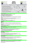
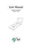
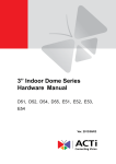
USER'S MANUAL
SWING GATE OPENER
Superjack and Easyjack are supplied by Pro-Lec UK
H/O 202 Bloomfield Road, Brislington, Bristol, BS4 3QU
Mobile Helpline. 07831 600024.
Important Safety Advice:
1. Knowledge of the relevant electro-technical regulations is required.
2. Training in use and maintenance of safety equipments is necessary.
3. Professional assistance is required when some mechanism adjustment is needed.
4. Always lay mains and control cables separately.
5. Test all equipment before initial operation.
6. Familiarise yourself with the use of the system before initial operation.
Contents of the Kit:
Wiring Diagram:
1
Installation Instructions : With optional easyfit brackets
1. Assemble the metal fixing brackets for the gate pillars.
And then fix the bracket to the pillar.
IMPORTANT:
If the hinge of your gate is more than 210mm from the edge of the pillar, it is necessary
to adapt the pillar and ensures the hinge is less than 210mm from the edge of the pillar.
2. Fix the actuator to the fixing bracket.
3. Unlock the actuator and adjust the stem of the actuator.
Normally, the factory preset is already 10mm from the end of the stroke.
If it is difficult to move the stem by hand, drive it electrically to avoid damage to the gate or kit.
2
4. Fix the metal bracket on the gate and check that the actuator does not touch the pillar.
If this is the case, it will be necessary to make a notch in the corner of the pillar.
5. Test the opening of the gate manually. It must move freely by itself.
If not, you must insert the stem of the actuator in another hole of the fixing bracket.
If no problems exist lock the actuator.
6. The position of the stop ends depends on the distance (E) of the gate hinge to
the edge of the pillar. The table below gives the position of the stop end according to (E).
3
Connection Diagram:
4
AC Wiring :
Inside of the control box, the wiring
should be like the photo on the left.
AC 230V in
Opening / Closing Learning:
Please activate this function before using this product otherwise the system will not drive
the gates properly. E.g.: The gate will not close completely or will not open to the intended
degree with some stroke length left unused.
To activate this function, press the "Auto" button on the PCB for 3 seconds while the PCB is on.
After release the "Auto" button and the system will enter the opening/closing learning mode as below:
1. The system will close the gates first.
Please remove any obstacle that could possibly block the gate.
Before the actuators start, the warning light will blink for 3 seconds.
Then Actuator 2 will close first, and then Actuator 1 will close 1 second later.
2. After 3 seconds, Actuator 1 will open the gate 1 fully,
after another 3 seconds, Actuator 2 will open the other gate 2 fully.
3. After 3 seconds Actuator 2 will close fully first, after another 3
Seconds, Actuator 1 will close fully.
4. System repeats the actions of point 2 and 3 one more time.
5. After 3 seconds, the system checks the operation of Actuator 1 and Actuator 2 together.
6. After the learning process is successful, the system is ready for use.
If the system blinks after the learning mode it indicates the learning mode has not completed properly.
Make sure that there's no obstacle on the way
and re start the learning mode.
NOTE:
If the Open/Close Learning couldn't be done successfully due to the gates being over-weight
the Current Limit needs to be adjusted. Please refer to P7 of this manual.
.
5
Remote Learning (activation of remote control for single-gate or dual-gate):
To activate the remote control service, carry out the following steps:
A. RF dual-gate learning: (dual-gate operation)
1. Press "RF2" key on the PCB for over 2 seconds
whilst the PCB is powered.
2. You'll see the LED light go out (learning mode entered),
press any key on the remote control,
LED will now blink 3 times (learning successful)
If the light is off after 10 seconds without flashing
(learning has failed, try the whole process again).
3. Please repeat steps 1 and 2 to activate another
remote control.
B. RF single-gate learning: (single-gate operation)
Press "RF1" key on the PCB and another key on the remote control as in steps 1~3 above.
Note: Up to 8 different RF remote control keys can be learnt for each function
by the system.
Remote Control:
Choose a key to program.
The remote control may have 4 keys on it. Choose two of them to activate RF learning for single-gate
and dual-gate operation separately.
Operation (open, close and stop) by remote control:
The remote operation is very simple: one key press will open the gate, next press to stop, next to close
the gate, next to stop...and so on.
When opening the gates:
1. Warning light will blink for 3 seconds, then Actuator 1 opens, 4 seconds later Actuator 2 opens.
2. If the gate hits something, Actuators will reverse for 3 seconds, and the warning light will blink until
the next command is received.
When closing the gates:
1. Warning light will blink for 3 seconds then Actuator 2 closes, 4 seconds later Actuator 1 closes.
2. If the gate hits something, Actuators will reverse for 3 seconds and the warning light will blink until
next command received.
Remark: The gate operation works properly only after successful Opening/Closing Learning.
6
Photocell (Optional):
1. During Opening:
When the loop of photocells has been interrupted, system will:
A. ignore, if the Actuator 1 has been activated. OR
B. stop, if the Actuator 1 hasn't been activated yet.
2. During Closing:
When the loop of photocells has been intercepted, system will stop closing the gates and then open
both gates simultaneously until the set position.
Auto close:
30 seconds or 60 seconds later (only when this function is enabled, depends on your setting of
key 1 of dip switch), warning light will blink for 3 seconds then Actuator 2 closes, 4 seconds later
Actuator 1 closes. When the process finished, warning light will be switched off.
Manual gate control on the PCB:
1. The operation is the same as remote: one key press will open the gate, next press to stop, next to
close the gate, next to stop...and so on.
2. Optional handset or external wall button is available. (Connected to O/C & GND terminals)
Clear RF memory:
Press the "Clear" key on the PCB for over 2 seconds while the PCB is on.
You'll see the LED blinking for 2.5 seconds and so the RF memory has been cleared.
Reset:
Press "Clear" key on the PCB and turn on AC power; keep pressing "Clear" key for over 2 seconds.
You'll see the LED blink for 5 times and be on.
Once the mentioned actions have been carried out, all RF data will be cleared.
Quick release:
Use the Key to unlock the actuator to move the gates manually.
Clutch adjustment:
The SW430 series features a clutch mechanism inside the actuator as an additional protection.
Any adjustment for the clutch requires professional assistance.
7
Settings of Dip Switches:
NOTE:
The current limit setting could be needed for adjustment according the weight of the gates
during Opening/Closing Learning.
Approx. current limit values for different dip switch setting:
Maximum Current Limit (This is max power and should not be
needed, if set to this unnecessarily you could shorten the life of motor,
Essentially try lower current limit first)
Second Highest Current Limit
Minimum Current Limit
When the user switches several of these switches on,
for safety reasons the system will choose the lowest
current limit setting automatically. (switch 4instead of switch 6 or 8)
8
Optional Accessories:
1 Set of Photocells
Operation of Photocells:
Select a proper installation site, where the sender and receiver can be along the same line
and at the same height.
Connect to the opener's PCB as wiring diagram above.
Power on the system, try and see if it works properly by interrupting the IR between
the sender and receiver for times. The relay in the receiver should respond accordingly
while LED switches ON and OFF.
With photocell properly installed, when triggered during opening the gates, the gates will ignore
the interruption and open. When triggered during closing the gates, the gates will stop closing and
the gates will both open simultaneously to the set position.
Specifications:
Model
Power supply
Power motor
Stroke lengths
Operation time
Open range
Duty cycle
Operation temperature
Fuses
backup battery
Automatic closing
Extra connections
RF Carriage
Control Range
EasyJack Swing gate opener
230VAC +/- 10%, 50Hz.
12VDC
350 mm.
Approx 15 seconds
120°
20%
-20°C - +65°C
Yes
Yes (optional, 12V, 7Ah.)
Adjustable (30 of 60 seconds)
Warning lamp. infra red photocell, battery
433.92 MHz
About 30 – 50 meter