1
West Pro-4 user manual – 59559
û BlueControl
More efficiency in engineering,
more overview in operating:
The projecting environment for the BluePort controllers
Description of symbols:
g General information
a General warning
l Attention: ESD sensitive devices
© PMA Prozeß- und Maschinen-Automation GmbH • Printed in Germany
All rights reserved. No part of this document may bereproduced or published in any form
or by any means without prior written permission from the copyright owner.
A publication of PMA Prozeß- und Maschinen Automation
P.O.Box 310229
D-34058 Kassel
Germany
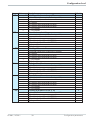
Contents
1
2
2.1
2.2
3
3.1
3.2
3.3
3.4
3.5
3.5.1
3.5.2
3.5.3
3.5.4
3.5.5
3.5.6
3.5.7
3.5.8
3.5.9
3.5.10
3.5.11
3.6
3.7
3.8
3.9
4
4.1
4.2
4.3
Mounting . . . . . . . . . . . . . . . . . . . . . . . . . . . . . . 5
Electrical connections . . . . . . . . . . . . . . . . . . . . . . . 6
Connecting diagram
. . . . . . . . . . . . . . . . . . . . . . . 6
Terminal connection. . . . . . . . . . . . . . . . . . . . . . . . . 7
Operation . . . . . . . . . . . . . . . . . . . . . . . . . . . . . 11
Front view . . . . . . . . . . . . . . . . . . . . . . . . . . . . 11
Behaviour after power-on . . . . . . . . . . . . . . . . . . . . . 12
Operating level . . . . . . . . . . . . . . . . . . . . . . . . . . . 12
Error list / Maintenance manager . . . . . . . . . . . . . . . . . 13
Self-tuning . . . . . . . . . . . . . . . . . . . . . . . . . . . . . 16
Preparation for self-tuning . . . . . . . . . . . . . . . . . . . . . .
Optimization after start-up or at the set-point . . . . . . . . . . . . .
Selecting the method ( ConF/ Cntr/ tunE) . . . . . . . . . . . .
Step attempt after start-up
. . . . . . . . . . . . . . . . . . . . .
Pulse attempt after start-up . . . . . . . . . . . . . . . . . . . . . .
Optimization at the set-point . . . . . . . . . . . . . . . . . . . . .
Optimization at the set-point for 3-point stepping controller . . . . .
Self-tuning start . . . . . . . . . . . . . . . . . . . . . . . . . . . .
Self-tuning cancellation . . . . . . . . . . . . . . . . . . . . . . .
Acknowledgement procedures in case of unsuccessful self-tuning
Examples for self-tuning attempts . . . . . . . . . . . . . . . . .
.
.
.
.
.
.
.
.
.
.
.
16
17
17
18
18
18
20
21
21
22
23
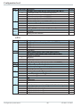
Manual self-tuning . . . .
Second PID parameter set
Alarm handling. . . . . .
Operating structure . . . .
Configuration level . . .
Configuration survey
Configuration parameters
Set-point processing . . .
.
.
.
.
.
.
.
.
24
25
26
28
29
29
30
43
.
.
.
.
.
.
.
.
.
.
.
.
. .
.
.
.
.
.
.
.
.
.
.
.
.
.
.
.
.
.
.
.
.
.
.
.
.
.
.
.
.
.
.
.
.
.
.
.
.
.
.
.
.
.
.
.
.
.
.
.
.
.
.
.
.
.
.
.
.
.
.
.
.
.
.
.
.
.
.
.
.
.
.
.
.
.
.
.
.
.
.
.
.
.
.
.
.
.
.
.
.
.
.
.
.
.
.
.
.
.
.
.
.
.
.
.
.
.
.
.
.
.
.
.
.
.
.
.
.
.
.
.
.
.
.
.
.
.
.
.
.
.
.
.
.
.
.
.
.
.
.
.
.
.
.
.
.
4.3.1
Set-point gradient / ramp . . . . . . . . . . . . . . . . . . . . . . . . 43
4.4
Switching behaviuor . . . . . . . . . . . . . . . . . . . . . . . . 44
4.4.1
4.4.2
Standard ( CyCl= 0 ) . . . . . . . . . . . . . . . . . . . . . . . . . 44
Switching attitude linear ( CyCl= 1 ) . . . . . . . . . . . . . . . . . 44
KS 90-1 / KS 92-1
3
4.4.3
4.4.4
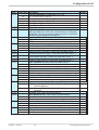
Switching attitude non-linear ( CyCl= 2 ) . . . . . . . . . . . . . . . 45
Heating and cooling with constant period ( CyCl= 3 ) . . . . . . . . 46
4.5
Configuration examples . . . . . . . . . . . . . . . . . . . . . . 47
4.5.1
4.5.2
4.5.3
4.5.4
4.5.5
4.5.6
4.5.7
4.5.8
5
5.1
5.2
5.3
5.3.1
5.3.2
6
7
7.1
7.2
On-Off controller / Signaller (inverse) . . . . . . . . . . .
2-point controller (inverse) . . . . . . . . . . . . . . . . .
3-point controller (relay & relay) . . . . . . . . . . . . . .
3-point stepping controller (relay & relay) . . . . . . . . .
Continuous controller (inverse) . . . . . . . . . . . . . . .
∆ - Y - Off controller / 2-point controller with pre-contact
Continuous controller with position controller . . . . . . .
Measured value output . . . . . . . . . . . . . . . . . . .
Parameter setting level .
Parameter survey
. . .
Parameters . . . . . . . .
Input scaling . . . . . . .
.
.
.
.
.
.
.
.
.
.
.
.
.
.
.
.
.
.
.
.
.
.
.
.
.
.
.
.
.
.
.
.
.
.
.
.
.
.
.
.
.
.
.
.
.
.
.
.
.
.
.
.
.
.
.
.
.
.
.
.
.
.
.
.
.
.
.
.
.
.
.
.
.
.
.
.
.
.
.
.
.
.
.
.
.
.
.
.
.
.
.
.
.
.
.
.
.
.
.
.
.
.
.
.
.
.
.
.
.
.
.
.
.
.
.
.
.
.
.
.
47
48
49
50
51
52
53
54
.
.
.
.
.
.
.
.
.
.
.
.
55
55
56
59
Input Inp.1 and InP.3 . . . . . . . . . . . . . 60
Input InP.2 . . . . . . . . . . . . . . . . . . . . . . . . . . . . . . . 60
Calibration level . . . . . . . . .
Special functions . . . . . . . . .
DAC®– motor actuator monitoring
O2 measurement . . . . . . . . . .
. . . . . . . . . . . . . . . . 61
. . . . . . . . . . . . . . . . 64
. . . . . . . . . . . . . . . 64
. . . . . . . . . . . . . . . . 66
7.2.1
7.2.2
Connection . . . . . . . . . . . . . . . . . . . . . . . . . . . . . . . 66
Configuration: . . . . . . . . . . . . . . . . . . . . . . . . . . . . . . 67
7.3
7.4
7.5
7.6
7.7
8
9
10
11
11.1
Linearization . . . . . . . . . . . . . . . . .
Loop alarm . . . . . . . . . . . . . . . . . .
Heating current input / heating current alarm
KS90-1 as Modbus master . . . . . . . . . .
Back-up controller (PROFIBUS) . . . . . .
BlueControl . . . . . . . . . . . . . . . . .
Versions . . . . . . . . . . . . . . . . . . .
Technical data . . . . . . . . . . . . . . .
Safety hints . . . . . . . . . . . . . . . . .
Resetting to factory setting, . . . . . . . . .
4
.
.
.
.
.
.
.
.
.
.
.
.
.
.
.
.
.
.
.
.
.
.
.
.
.
.
.
.
.
.
.
.
.
.
.
.
.
.
.
.
.
.
.
.
.
.
.
.
.
.
.
.
.
.
.
.
.
.
.
.
.
.
.
.
.
.
.
.
.
.
.
.
.
.
.
.
.
.
.
.
.
.
.
.
.
.
.
.
.
.
.
.
.
.
.
.
.
.
.
.
.
.
.
.
.
.
.
.
.
.
68
69
69
70
70
71
72
73
77
78
KS 90-1 / KS 92-1
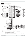
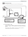
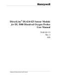
Mounting
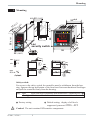
1 Mounting
min.48 (1.89")
(1.77"
SP.E SP.2
+0.02
)
92 +0,8
(3.62" +0.03)
Loc
security switch
F
è
Ada
Err
o
C
SP.E
para
func
Ada
Err
45
1200
para
func
SP.2
96 (3.78")
°C
°F
+0,6
3
4
920.1
44
1199
2
921.2
run
3
SP.E
2
1
SP.2
run
1
96
8
+0,8
)
5"
6
.
(4
92
11
")
(0 1 .
.0 .1
4. 0
.0
.4
")
10
.4
(0
92 +0,8
F
KS 92-1 advanced
KS 92-1 advanced
KS 90-1 advanced
96
8
11
10
48 (1.89")
max.
60°C
min.
0°C
Ü
max.
95% rel.
%
*
or:
Ü
*
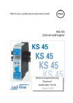
Safety switch:
For access to the safety switch, the controller must be withdrawn from the housing. Squeeze the top and bottom of the front bezel between thumb and forefinger
and pull the controller firmly from the housing.
Loc
1
l
open
closed
Access to the levels is as adjusted by means of BlueControl (engineering tool) 2
1
all levels accessible wihout restriction
Factory setting
2
Default setting: display of all levels
suppressed, password PASS = OFF
Caution! The unit contains ESD-sensitive components.
KS 90-1 / KS 92-1
5
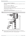
Electrical connections
2 Electrical connections
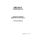
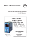
2.1 Connecting diagram
90...250V
24 V UC
1
2
3
OUT1
4
5
6
2
OUT3
3
10
11
12
V
KS90-1.4-...
KS90-1.5-...
OUT4
13
14
15
V
KS90-1.2-...
5
d
bc e a
7
di2
4
5
6
7
8
9
10
11
12
13
14
15
(16)
17
7
8
9
OUT2
di1
1
2
3
Option
1
g
HC mA f
mA
0%
5
INP3
6
KS90-1..-.1...
100%
(mV)
INP2
Volt
mA
INP1
4
(mV)
a
b
c
e
d
1
di2
8
3
UT
+24V DC
OUT5
OUT6
24V GND
!
RXD-B
GND
RXD-A
DATA B
DATA A
RS485
TXD-B
TXD-A
5
6
7
8
9
10
11
12
VP (5V)
13
DGND
14
RxD/TxD-N
15
(16)
17
RxD/TxD-P
Schirm/
Screen
DGND
PROF IBUS -DP
RGND
4
Adapter
di3
9
0
(2)
9
220 [
8
5
4
4
8
3
390 [
7
VP (5V)
3
7
2
2
6
1
RS422
5
9
6
1
Profibus DP
Modbus RTU
g
390 [
max.
1200m
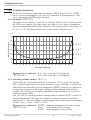
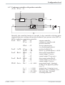
Dependent of order, the controller is fitted with :
w flat-pin terminals 1 x 6,3mm or 2 x 2,8mm to DIN 46 244 or
w screw terminals for 0,5 to 2,5mm²
On instruments with screw terminals, the insulation must be stripped by min.
12 mm. Choose end crimps accordingly!
Connecting diagram
6
KS 90-1 / KS 92-1
Electrical connections
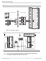
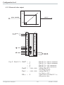
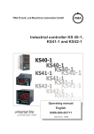
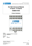
2.2 Terminal connection
Power supply connection 1
See chapter "Technical data"
Connection of outputs OUT1/2 2
2 OUT1/2 heating/cooling
Relay outputs (250V/2A), potential-free
changeover contact
1
Connection of outputs OUT3/4 3
a relay (250V/2A), potential-free
changeover contact
universal output
b current (0/4...20mA)
c voltage (0/2...10V)
d transmitter supply
e logic (0..20mA / 0..12V)
L
1
2
3
2
4
6
3
4
5
6
7
8
9
10
11
12
13
14
5
7
9
8
10
11
12
13
14
15
(16)
Connection of input INP1 4
Input mostly used for variable x1 (process value)
a thermocouple
b resistance thermometer (Pt100/ Pt1000/ KTY/ ...)
c current (0/4...20mA)
d voltage (0/2...10V)
N
Connection of input INP2 5
f heating current input (0..50mA AC)
or input for ext. set-point (0/4...20mA)
g potentiometer input for position
feedback
7
+
L
1
2
1
2
3
3
4
5
6
4
5
Logik
7
8
9
10
11
12
13
14
15
Connection of input INP3 6
As input INP1, but without voltage
KS 90-1 / KS 92-1
17
5 INP2 current tansformer
Connection of input INP2 5
a Heating current input (0...50mA AC)
or input for ext. Set-point (0/4...20mA)
b Potentiometer input for position
feedback
Connection of inputs di1, di2 7
Digital input, configurable as switch or
push-button
15
SSR
_
+
6
7
8
9
10
11
12
13
14
15
(16)
17
N
Terminal connection
Electrical connections
Connection of inputs di2/3 8 (option)
Digital inputs (24VDC external), galvanically isolated, configurable as switch or
push-button
Connection of output UT 9 (option)
Supply voltage connection for external energization
Connection of outputs OUT5/6 0 (option)
Digital outputs (opto-coupler), galvanic isolated, common positive control voltage, output rating: 18...32VDC
Connection of bus interface ! (option)
PROFIBUS DP or RS422/485 interface with Modbus RTU protocol
8 9 di2/3, 2-wire transmitter supply
10
11
12
J
13
14
15
5mA
+24VDC
13 +
14 -
Option
OUT3
15
(16)
17
1
(2)
5mA
0V
3
4
5
17,5V
22mA
+
-
6
7
8
9
10
11
+
12
13
1
14
3
2
-
K
15
(16)
17
J
g
Analog outputs OUT3 or OUT4 and transmitter supply UT are connected to
different voltage potentials. Therefore, take care not to make an external galvanic
connection between OUT3/4 and UT with analog outputs!
Terminal connection
8
KS 90-1 / KS 92-1
Electrical connections
3 OUT3 transmitter supply
13V
22mA
- 10
+ 11
11
12
12
13
14
15
13 +
14 -
15
(16)
17
1
3
2
K
1
(2)
10
11
12
RT = 120...200 Ohm
RT
DATA B
DATA A
11
12
13
14
14
1
(2)
10
11
12
13
14
1
15
3
3
4
4
4
5
5
5
6
6
6
7
7
7
8
8
8
9
9
9
10
10
10
12
RGND
13
14
DATA B
15
(16)
DATA A
17
11
11
12
12
13
14
15
(16)
17
15
(2)
3
11
RGND
10
13
15
option
option
option
9 RS485 interface (with RS232-RS485 interface converter) *
RGND
DATA B
DATA A
13
PC
14
15
(16)
17
R=100 Ohm
max. 1000m
"Twisted Pair” cable
RGND connection optional
J
*
RS485-RS232
converter
RT
RT = 120...200 Ohm
Interface description Modbus RTU in speperate manual: see page 71.
KS 90-1 / KS 92-1
9
Terminal connection
Electrical connections
3 OUT3 as logic output with solid-state relay (series and parallel connection)
Series connection
Parallel connection
SSR
_
+
SSR
_
Imax=22mA
+
12
SSR
_
4V
SSR
_
10
11
12V
+
Imax=22mA
4V
12V
12
SSR
_
+
+
Logic
10
11
4V
KS90-1 connecting example:
L1
L2
Fuse
Fuse
KS90-1
3
4
5
6
7
8
9
10
11
Logik
12
13
14
15
4
5
6
7
8
9
10
11
12
13
14
Fuse
1
1
2
3
2
Contactor
3
TB 40-1
Temperaturelimiter
1
2
1 TB 40-1 Temperaturelimiter
Standard-version (3 Relays):
TB40-100-0000D-000
r further versions on request
1
SSR
_
+
4
5
6
7
8
9
10
11
12
13
15
14
(16)
17
+
15
Heating
+
Resetkey
N1
N2
Using a temperature limiter is recommendable in systems where
a CAUTION:
overtemperature implies a fire hazard or other risks.
Terminal connection
10
KS 90-1 / KS 92-1
Operation
3 Operation
3.1 Front view
1199
°C
°F
p
para
ffunc
Ada
A
Err
1200
§"
SP.E
E
SP.2
SP
1
2
2
3
9
0
3
5
6
7
8
!
F
$
(
1
$
%
&
/
(
2
3
4
920.1
92
o
para
func
4
Ada
Err
C
921.2
9
§"! 0
%
(
1
3
5
7
9
!
§
1
SP.E
4
SP.2
/
&
3
SP.E
4
5
6
7
8
2
SP.2
1
F
/
&
%
$
Statuses of switching outputs OuT.1... 6
2 Process value display
Setpoint or correcting variable display
4 °C or °F display signalling
Signals ConF- and PArA level
6 Signals activated function key
Selft-tuning active
8 Entry into the error list
Bargraph or plain text display
0 Setpoint SP.2 is effective
Setpoint SP.E is effective
" Setpoint gradient is effective
Manual-automatic switchover: Off: automatic On: manual mode (adjustment possible)
Blinks: manual mode (adjustment not possible (r ConF/ Cntr/ MAn))
Enter key: call up extented operating level / error list
Up/ down keys: changing setpoint or correcting variable
automatic/manual or other functions ( r ConF/LOGI)
freely configurable function key with pure controller operation
PC connection for BlueControl (engineering tool)
LED colours: LED 1, 2, 3, 4: yellow, Bargraph: red, other LEDs: red
g
In the upper display line, the process value is always displayed. At parameter,
configuration, calibration as well as extended operating level, the bottom display
line changes cyclically between parameter name and parameter value.
KS 90-1 / KS 92-1
11
Front view
Operation
3.2 Behaviour after power-on
After supply voltage switch-on, the unit starts with the operating level.
The unit is in the condition which was active before power-off.
If the controller was in manual mode at supply voltage switch-off, the controller
will re-start with the last output value in manual mode at power-on.
3.3 Operating level
The content of the extended operating level is determined by means of BlueControl (engineering tool). Parameters which are used frequently or the display of
which is important can be copied to the extended operating level.
Automatic
1199
1200
Manual
iÒ i
È
Ì
time
out
Ù
Y 21
Ù
Ò
È
Ì
time
out
1199
1199
1200
Y 21
Ù
1199
È
Ì
only
display
Ù
Extended operating level
time
out
Error list (if error exists)
126
FbF.1
Err
Behaviour after power-on
126
Display
2
switching
Err
12
KS 90-1 / KS 92-1
Operation
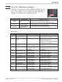
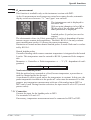
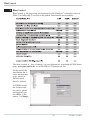
3.4 Error list / Maintenance manager
With one or several errors, the extended operating level always starts with the error list. Signalling an actual entry in
the error list (alarm, error) is done by the Err LED in the
display. To reach the error list press Ù twice.
Err LED status
blinks
(status 2)
lit
(status 1)
off
(status 0)
Signification
Alarm due to existing
error
Error removed, alarm
not acknowledged
No error, all alarm
entries deleted
-
1199
°C
°F
para
func
Ada
Err
1200
SP.E
SP.2
Proceed as follows
Determine the error type in the error list
After error correction the unit changes to status 1
Acknowledge the alarm in the error list pressing key ÈorÌ
The alarm entry was deleted (status 0).
-Not visible except when acknowledging
Error list:
Name
E.1
E.2
E.3
E.4
FbF.1
Sht.1
POL.1
FbF.2
Sht.2
POL.2
FbF.3
Sht.3
POL.3
KS 90-1 / KS 92-1
Description
Cause
Possible remedial action
Internal error,
- E.g. defective EEPROM - Contact PMA service
cannot be removed
- Return unit to our factory
Internal error, can be - e.g. EMC trouble
- Keep measurement and power supply
reset
cables in separate runs
- Ensure that interference suppression
of contactors is provided
- Check interaction of configuration /
Configuration error, - wrong configuration
can be reset
- missing configuration
parameters
Hardware error
- Codenumber and
- Contact PMA service
- Elektronic-/Optioncard must be
hardware are not
identical
exchanged
- Replace INP1 sensor
Sensor break INP1 - Sensor defective
- Check INP1 connection
- Faulty cabling
- Replace INP1 sensor
Short circuit INP1 - Sensor defective
- Faulty cabling
- Check INP1 connection
- Reverse INP1 polarity
INP1polarity error - Faulty cabling
- Replace INP2 sensor
Sensor break INP2 - Sensor defective
- Check INP2 connection
- Faulty cabling
- Replace sensor INP2
Short circuit INP2 - Sensor defective
- Faulty cabling
- Check INP2 connection
- Faulty cabling
- Reverse INP2 polarity
INP2 polarity
- Replace INP3 sensor
Sensor break INP3 - Sensor defective
- Check INP3 connection
- Faulty cabling
- Replace sensor INP3
Short circuit INP3 - Sensor defective
- Faulty cabling
- Check INP3 connection
- Faulty cabling
- Reverse INP3 polarity
INP3 polarity
13
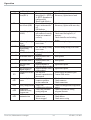
Error list / Maintenance manager
Operation
Name
HCA
Description
Heating current
alarm (HCA)
SSr
Heating current
short circuit (SSR)
LooP
Control loop alarm
(LOOP)
AdA.H
Self-tuning heating
alarm
(ADAH)
Self-tuning heating - See Self-tuning cooling
alarm cooling
error status
(ADAC)
stored limit alarm 1 - adjusted limit value 1
exceeded
stored limit alarm 2 - adjusted limit value 2
exceeded
stored limit alarm 3 - adjusted limit value 3
exceeded
time limit value
- adjusted number of
message
operating hours reached
duty cycle message - adjusted number of duty
(digital ouputs)
cycles reached
Internal error in DP - self-test error
module
- internal communication
interrupted
- bus error
No access by bus
master
- connector problem
- no bus connection
Faulty configuration - Faulty DP
configuration telegram
- Faulty DP parameter
Inadmissible
parameter setting
setting telegram
telegram sent
- Bus error
No data
communication
- Address error
- Master stopped
AdA.C
LiM.1
Lim.2
Lim.3
Inf.1
Inf.2
E.5
dp.1
dp.2
dp.3
dp.4
Error list / Maintenance manager
Cause
- Heating current circuit
interrupted, I< HC.A or
I> HC.A (dependent of
configuration)
- Heater band defective
- Current flow in heating
circuit with controller
off
- SSR defective
- Input signal defective or
not connected correctly
- Output not connected
correctly
Possible remedial action
- Check heating current circuit
- If necessary, replace heater band
- Check heating current circuit
- If necessary, replace solid-state relay
- Check heating or cooling circuit
- Check sensor and replace it, if
necessary
- Check controller and switching
device
- See Self-tuning heating - see Self-tuning heating error status
error status
- see Self-tuning cooling error status
- check process
- check process
- check process
- application-specific
- application-specific
- Switch on the instrument again
- Contact PMA service
-
Check cable
Check connector
Check connections
Check DP configuration telegram in
master
- Check DP parameter setting
telegram in master
- Check cable connection
- Check address
- Check master setting
14
KS 90-1 / KS 92-1
Operation
g
g
Saved alarms (Err-LED is lit) can be acknowledged and deleted with the digital
input di1/2/3, the è-key or the Ò-key.
Configuration, see page 37: ConF / LOGI / Err.r
If an alarm is still valid that means the cause of the alarm is not removed so far
(Err-LED blinks), then other saved alarms can not be acknowledged and deleted.
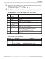
Self-tuning heating ( ADA.H) and cooling ( ADA.C) error status:
Error
status
0
3
4
5
6
7
8
9
Description
Behaviour
No error
Faulty control action
No response of process
variable
Low reversal point
Danger of exceeded
set-point (parameter
determined)
Output step change
too small (dy > 5%)
Set-point reserve too
small
Re-configure controller (inverse i direct)
The control loop is perhaps not closed: check sensor, connections
and process
Increase ( ADA.H) max. output limiting Y.Hi or decrease (
ADA.C) min. output limiting Y.Lo
If necessary, increase (inverse) or reduce (direct) set-point
Increase ( ADA.H) max. output limiting Y.Hi or reduce (
ADA.C) min. output limiting Y.Lo
Acknowledgment of this error message leads to switch-over to
automatic mode.If self-tuning shall be continued,
increase set-point (invers), reduce set-point (direct)
or decrease set-point range
(r PArA / SEtp / SP.LO and SP.Hi )
Impulse tuning failed The control loop is perhaps not closed: check sensor, connections
and process
DAC function ( DAC) error status:
Error status
0
3
4
5
6
KS 90-1 / KS 92-1
Description
No error
Output is blocked
Wrong method of operation
Fail at Yp measurement
Calibration error
15
Behaviour
Check the drive for blockage
Wrong phasing, defect motor capacitor
Check the connection to the Yp input
Manual calibration necessary
Error list / Maintenance manager
Operation
3.5 Self-tuning
For determination of optimum process parameters, self-tuning is possible.
After starting by the operator, the controller makes an adaptation attempt, whereby the process characteristics are used to calculate the parameters for fast line-out
to the set-point without overshoot.
The following parameters are optimized when self-tuning:
Parameter set 1:
Pb1
- Proportional band 1 (heating) in engineering units [e.g. °C]
ti1
- Integral time 1 (heating) in [s]r only, unless set to OFF
td1
- Derivative time 1 (heating) in [s]r only, unless set to OFF
t1
- Minimum cycle time 1 (heating) in [s]r only, unless Adt0 was
set to “no self-tuning”
during configuration by means of
BlueControl®.
Pb2
ti2
td2
t2
- Proportional band 2 (cooling) in engineering units [e.g. °C]
- Integral time 2 (cooling) in [s]r only, unless set to OFF
- Derivative time 2 (cooling) in [s]r only, unless set to OFF
- Minimum cycle time 2 (cooling) in [s] r only, unless Adt0
was set to “no
self-tuning” during configuration by means of
BlueControl® .
Parameter set 2: analogous to parameter set 1 (see page 25)
3.5.1 Preparation for self-tuning
w Adjust the controller measuring range as control range limits. Set values
rnG.L and rnG.H to the limits of subsequent control.
(ConfigurationrControllerrlower and upper control range limits)
ConFrCntrr rnG.L and rnG.H
w Determine which parameter set shall be optimized.
-The instantaneously effective parameter set is optimized.
r Activate the relevant parameter set (1 or 2).
w Determine which parameter set shall be optimized (see tables above).
w Select the self-tuning method
see chapter 3.5.3
-Step attempt after start-up
-Pulse attempt after start-up
-Optimization at the set-point
Self-tuning
16
KS 90-1 / KS 92-1
Operation
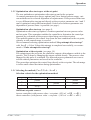
3.5.2 Optimization after start-up or at the set-point
The two methods are optimization after start-up and at the set-point.
As control parameters are always optimal only for a limited process range, various methods can be selected dependent of requirements. If the process behaviour
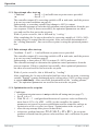
is very different after start-up and directly at the set-point, parameter sets 1 and 2
can be optimized using different methods. Switch-over between parameter sets
dependent of process status is possible (see page ).
Optimization after start-up: (see page 4)
Optimization after start-up requires a certain separation between process value
and set-point. This separation enables the controller to determine the control parameters by evaluation of the process when lining out to the set-point.
This method optimizes the control loop from the start conditions to the set-point,
whereby a wide control range is covered.
We recommend selecting optimization method “Step attempt after start-up”
with tunE = 0 first. Unless this attempt is completed successfully, we recommend a “Pulse attempt after start-up”.
Optimization at the set-point: (see page 18)
For optimizing at the set-point, the controller outputs a disturbance variable to the
process. This is done by changing the output variable shortly. The process value
changed by this pulse is evaluated. The detected process parameters are converted into control parameters and saved in the controller.
This procedure optimizes the control loop directly at the set-point. The advantage
is in the small control deviation during optimization.
3.5.3 Selecting the method ( ConF/ Cntr/ tunE)
Selection criteria for the optimization method:
tunE = 0
tunE = 1
tunE = 2
Step attempt after start-up
sufficient set-point reserve is
provided
always step attempt after
start-up
Pulse attempt after start-up
Optimization at the set-point
sufficient set-point reserve is not
provided
sufficient set-point reserve is sufficient set-point reserve is not
provided
provided
Sufficient set-point reserve:
inverse controller:(with process value < set-point- (10% of rnGH - rnGL)
direct controller: (with process value > set-point + (10% of rnGH - rnGL)
KS 90-1 / KS 92-1
17
Self-tuning
Operation
3.5.4 Step attempt after start-up
Condition:
- tunE = 0 and sufficient set-point reserve provided
or
- tunE = 2
The controller outputs 0% correcting variable or Y.Lo and waits, until the process
is at rest (see start-conditions on page 8).
Subsequently, a correcting variable step change to 100% is output.
The controller attempts to calculate the optimum control parameters from the process response. If this is done successfully, the optimized parameters are taken
over and used for line-out to the set-point.
With a 3-point controller, this is followed by “cooling”.
After completing the 1st step as described, a correcting variable of -100% (100%
cooling energy) is output from the set-point. After successfull determination of
the “cooling parameters”, line-out to the set-point is using the optimized parameters.
3.5.5 Pulse attempt after start-up
Condition: - tunE = 1 and sufficient set-point reserve provided.
The controller outputs 0% correcting variable or Y.Lo and waits, until the process
is at rest (see start conditions page 8)
Subsequently, a short pulse of 100% is output (Y=100%) and reset.
The controller attempts to determine the optimum control parameters from the
process response. If this is completed successfully, these optimized parameters
are taken over and used for line-out to the set-point.
With a 3-point controller, this is followed by “cooling”.
After completing the 1st step as described and line-out to the set-point, correcting
variable "heating" remains unchanged and a cooling pulse (100% cooling energy)
is output additionally. After successful determination of the “cooling parameters”, the optimized parameters are used for line-out to the set-point.
3.5.6 Optimization at the set-point
Conditions:
w A sufficient set-point reserve is not provided at self-tuning start (see page 17).
w tunE is 0 or 1
w With Strt = 1 configured and detection of a process value oscillation by
more than ± 0,5% of (rnG.H - rnG.L) by the controller, the control
parameters are preset for process stabilization and the controller realizes an
optimization at the set-point (see figure “Optimization at the set-point”).
w when the step attempt after power-on has failed
w with active gradient function ( PArA/ SETP/ r.SP≠ OFF), the set-point
gradient is started from the process value and there isn't a sufficient set-point
reserve.
Self-tuning
18
KS 90-1 / KS 92-1
Operation
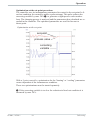
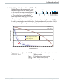
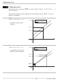
Optimization-at-the-set-point procedure:
The controller uses its instantaneous parameters for control to the set-point. In lined out condition, the controller makes a pulse attempt. This pulse reduces the
correcting variable by max. 20% 1, to generate a slight process value undershoot. The changing process is analyzed and the parameters thus calculated are recorded in the controller. The optimized parameters are used for line-out to
theset-point.
Optimization at the set-point
set-point
process value
correcting
variable
With a 3-point controller, optimization for the “heating“ or “cooling” parameters
occurs dependent of the instantaneous condition.
These two optimizations must be started separately.
1 If the correcting variable is too low for reduction in lined out condition it is
increased by max. 20%.
KS 90-1 / KS 92-1
19
Self-tuning
Operation
3.5.7 Optimization at the set-point for 3-point stepping controller
With 3-point stepping controllers, the pulse attempt can be made with or without
position feedback. Unless feedback is provided, the controller calculates the motor actuator position internally by varying an integrator with the adjusted actuator
travel time. For this reason, precise entry of the actuator travel time (tt), as time
between stops is highly important. Due to position simulation, the controller
knows whether an increased or reduced pulse must be output. After supply voltage switch-on, position simulation is at 50%. When the motor actuator was varied
by the adjusted travel time in one go, internal calculation occurs, i.e. the position
corresponds to the simulation:
Simulation
actual position
Internal calculation
tt
Internal calculation always occurs, when the actuator was varied by travel time
tt in one go , independent of manual or automatic mode. When interrupting the
variation, internal calculation is cancelled. Unless internal calculation occurred
already after self-tuning start, it will occur automatically by closing the actuator
once.
Unless the positioning limits were reached within 10 hours, a significant deviation between simulation and actual position may have occurred. In this case, the
controller would realize minor internal calculation, i.e. the actuator would be closed by 20 %, and re-opened by 20 % subsequently. As a result, the controller
knows that there is a 20% reserve for the attempt.
Self-tuning
20
KS 90-1 / KS 92-1
Operation
3.5.8 Self-tuning start
Start condition:
w For process evaluation, a stable condition is required. Therefore, the
controller waits until the process has reached a stable condition after
self-tuning start.
The rest condition is considered being reached, when the process value
oscillation is smaller than ± 0,5% of (rnG.H - rnG.L).
w For self-tuning start after start-up, a 10% difference from (SP.LO ... SP.Hi)
is required.
g
Self-tuning start can be blocked via BlueControl® (engineering tool) ( P.Loc).
Strt = 0
Only manual start by pressing keys Ù and È
simultaneously or via interface is possible.
Strt = 1
Manual start by press keys Ù and È simultaneously
via interface and automatic start after power-on and detection
of process oscillations.
Ada LED status
Signification
blinks
Waiting, until process
calms down
lit
Self-tuning is running
off
Self-tuning not activ
or ended
1199
°C
°F
para
func
Ada
Err
1200
SP.E
SP.2
3.5.9 Self-tuning cancellation
By the operator:
Self-tuning can always be cancelled by the operator. For this, press Ù and È
key simultaneously.With controller switch-over to manual mode after self-tuning
start, self-tuning is cancelled. When self-tuning is cancelled, the controller will
continue operating using the old parameter values.
By the controller:
If the Err LED starts blinking whilst self-tuning is running, successful self-tuning
is prevented due to the control conditions. In this case, self-tuning was cancelled
by the controller. The controller continues operating with the old parameters in
automatic mode. In manual mode it continues with the old controller output value.
KS 90-1 / KS 92-1
21
Self-tuning
Operation
3.5.10 Acknowledgement procedures in case of unsuccessful self-tuning
1. Press keys Ù and È simultaneously:
The controller continues controlling using the old parameters in automatic
mode. The Err LED continues blinking, until the self-tuning error was
acknowledged in the error list.
2. Press key Ò (if configured):
The controller goes to manual mode. The Err LED continues blinking,
until the self-tuning error was acknowleged in the error list.
3. Press key Ù :
Display of error list at extended operating level. After acknowledgement
of the error message, the controller continues control in automatic mode using
the old parameters.
Cancellation causes:
r page 15: "Error status self-tuning heating ( ADA.H) and cooling ( ADA.C)"
Self-tuning
22
KS 90-1 / KS 92-1
Operation
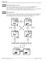
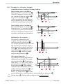
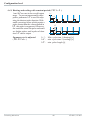
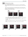
3.5.11 Examples for self-tuning attempts
(controller inverse, heating or heating/cooling)
Start: heating power switched on
Heating power Y is switched off (1).
When the change of process value X
was constant during one minute (2),
the power is switched on (3).
At the reversal point, the self-tuning attempt is finished and the new parameter
are used for controlling to set-point W.
Start: heating power switched off
The controller waits 1,5 minutes (1).
Heating power Y is switched on (2).
At the reversal point, the self-tuning
attempt is finished and control to the
set-point is using the new parameters.
X
W
2
t
100%
Y
0%
Start r
1
3
t reversal point
blinks
X
W
100%
Y
0%
start r
t
2
1
t reversal point
blinks
Self-tuning at the set-point a
The process is controlled to the
set-point. With the control deviation
constant during a defined time (1)
(i.e. constant separation of process value
and set-point), the controller outputs a
reduced correcting variable pulse (max.
20%) (2). After determination of the
control parameters using the process
characteristic (3), control is started
using the new parameters (4).
a
2
r t
X
W
100%
Y
0%
Start r
t
1
3
4
blinks
Three-point controller a
3
r t
X
The parameter for heating and cooling are
W
determined in two attempts. The heating
power is switched on (1). Heating parat reversal
point
meters Pb1, ti1, td1 and t1 are de+100%
termined at the reversal point. Control to
Y 0%
the set-point occurs(2). With constant
-100%
Start r
2
5
1
4
control deviation, the controller provides a
cooling correcting variable pulse (3). After determining its cooling parameters
Pb2, ti2, td2 and t2 (4) from the
process characteristics , control operation is started using the new parameters (5).
During phase 3, heating and cooling are done simultaneously!
KS 90-1 / KS 92-1
23
t
Self-tuning
Operation
3.6 Manual self-tuning
The optimization aid can be used with units on which the control parameters shall
be set without self-tuning.
For this, the response of process variable x after a step change of correcting variable y can be used. Frequently, plotting the complete response curve (0 to 100%)
is not possible, because the process must be kept within defined limits. Values Tg
and xmax (step change from 0 to 100 %) or ∆t and ∆x (partial step response) can
be used to determine the maximum rate of increase vmax.
100%
y
Yh
0%
t
x
Tg
Xmax
{X
{t
t
Tu
y
Yh
Tu
Tg
Xmax
=
=
=
=
=
correcting variable
control range
delay time (s)
recovery time (s)
maximum process value
Xmax { x
= max. rate of increase of process value
=
{t
Tg
The control parameters can be determined from the values calculated for delay
time Tu , maximum rate of increase vmax, control range Xh and characteristic K
according to the formulas given below. Increase Xp, if line-out to the set-point
oscillates.
Vmax
Manual self-tuning
=
24
KS 90-1 / KS 92-1
Operation
Parameter adjustment effects
Parameter
Pb1 higher
lower
td1 higher
lower
ti1 higher
lower
Control
increased damping
reduced damping
reduced damping
increased damping
increased damping
reduced damping
Formulas
K = Vmax * Tu
With 2-point and
3-point controllers,
the cycle time must be
adjusted to
t1 / t2 ≤ 0,25 * Tu
Line-out of disturbances
slower line-out
faster line-out
faster response to disturbances
slower response to disturbances
slower line-out
faster line-out
controller behavior
PID
PD
PI
P
3-point-stepping
Pb1 [phy. units]
1,7 * K
0,5 * K
2,6 * K
K
1,7 * K
Start-up behaviour
slower reduction of duty cycle
faster reduction of duty cycle
faster reduction of duty cycle
slower reduction of duty cycle
slower reduction of duty cycle
faster reduction of duty cycle
td1 [s]
2 * Tu
Tu
OFF
OFF
Tu
ti1 [s]
2 * Tu
OFF
6 * Tu
OFF
2 * Tu
3.7 Second PID parameter set
The process characteristic is frequently affected by various factors such as process value, correcting variable and material differences.
To comply with these requirements, KS 90-1 can be switched over between two
parameter sets.
Parameter sets PArA and PAr.2 are provided for heating and cooling.
Dependent of configuration ( ConF/LOG/Pid.2), switch-over to the second parameter set ( ConF/LOG/Pid.2) is via one of digital inputs di1, di2, di3,
key è or interface (OPTION).
g
Self-tuning is always done using the active parameter set, i.e. the second
parameter set must be active for optimizing.
KS 90-1 / KS 92-1
25
Second PID parameter set
Operation
3.8 Alarm handling
Max. three alarms can be configured and assigned to the individual outputs. Generally, outputs OuT.1... OuT.6 can be used each for alarm signalling. If more
than one signal is linked to one output the signals are OR linked. Each of the 3 limit values Lim.1 … Lim.3 has 2 trigger points H.x (Max) and L.x (Min), which
can be switched off individually (parameter = “OFF”). Switching difference
HYS.x and delay dEl.x of each limit value is adjustable.
* Operating principle relative alarm
L.1 = OFF
Ü Operaing principle absolut alarm
L.1 = OFF
InL.1
InH.1
SP
InL.1
InH.1
H.1
H.1
HYS.1
HYS.1
LED
LED
H.1 = OFF
H.1 = OFF
InL.1
InH.1
SP
InL.1
InH.1
L.1
L.1
HYS.1
HYS.1
LED
LED
SP
InL.1
InH.1
InL.1
InH.1
L.1
H.1
L.1
HYS.1
LED
HYS.1
HYS.1
LED
2
LED
H.1
HYS.1
2
LED
1: normally closed ( ConF/ Out.x / O.Act=1 ) (see examples in the drawing)
2: normally open ( ConF/ Out.x / O.Act= 0 )(inverted output relay action)
Alarm handling
26
KS 90-1 / KS 92-1
Operation
g
The variable to be monitored can be selected seperately for each alarm via
configuration
The following variables can be monitored:
w process value
w control deviation xw (process value - set-point)
w control deviation xw + suppression after start-up or set-point change
After switching on or set-point changing, the alarm output is suppressed,
until the process value is within the limits for the first time. At the latest after
expiration of time 10 ti1, the alarm is activated. (ti1 = integral time 1;
parameter r Cntr)
If ti1 is switched off (ti1 = OFF), this is interpreted as Î, i.e. the alarm
is not activated, before the process value was within the limits once.
w Measured value INP1
w Measured value INP2
w Measured value INP3
w effective set-point Weff
w correcting variable y (controller output)
w Deviation from SP internal
w x1 - x2
w control deviation xw + suppression after start-up or setpoint change
without time limit.
- after switch-on or setpoint change, alarm output is suppressed, until the
process value was within the limits once.
w
w
g
If measured value monitoring + alarm status storage is chosen ( ConF / Lim /
Fnc.x = 2/4), the alarm relay remains switched on until the alarm is resetted in
the error list ( Lim 1..3 = 1).
KS 90-1 / KS 92-1
27
Alarm handling
Operation
3.9 Operating structure
After supply voltage switch-on, the controller starts with the operating levels.
The controller status is as before power off.
1199
1200
Ù
3 sec.
1199
para
PArA
Ì
Ù
PASS
1199
para
Ù
ConF
Ì
PASS
1199
CAL
Ì
Ù
PASS
1199
End
Ù
g
PArA - level:
g
ConF - level:
At ConF - level, the right decimal point of bottom
display line blinks.
When safety switch Loc is open, only the levels enabled by mePASS ans of BlueControl (engineering tool) are visible and accessible
by entry of the password also adjusted by means of BlueControl
(engineering tool). Individual parameters accessible without password must be
copied to the extended operating level.
g
Factory setting:Safety switch Loc closed: all levels accessible without
restriction, password PASS = OFF.
Safety switch
Loc
closed
open
open
open
Operating structure
At PArA - level, the right decimal point of the bottom
display line is lit continuously.
Password entered
with BluePort®
OFF / password
OFF / password
OFF
Password
Function disabled or
enabled with BluePort®
disabled / enabled
disabled
enabled
enabled
28
Access via the instrument
front panel:
enabled
disabled
enabled
enabled after password entry
KS 90-1 / KS 92-1
Configuration level
4 Configuration level
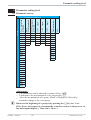
4.1 Configuration survey
LOGI
Digital inpu ts
Othr Display,
operation, interface
O.tYP
O.Act
Y.1
Y.2
Lim.1
Lim.2
Lim.3
dAc.A
LP.AL
HC.AL
HC.SC
P.End
FAi.1
FAi.2
FAi.3
OuT.0
Out.1
O.Src
Out.5/6
Output 5/6
O.tYP
O.Act
OuT.0
Out.1
O.Src
O.FAI
Y.1
Y.2
Lim.1
Lim.2
Lim.3
dAc.A
LP.AL
HC.AL
HC.SC
FAi.1
FAi.2
FAi.3
dP.Er
See output 1
OUt.2
Output 2
OUt.4
Output 4
Fnc.2
Src.2
Fnc.3
Src.3
HC.AL
LP.AL
dAc.A
OUt.3
Output 3
C.Fnc S.Lin Corr S.Typ
C.dif Corr In.F Corr
mAn In.F
In.F
C.Act
FAIL
rnG.L
rnG.H
CYCL
tunE
Strt
O.Act
Y.1
Y.2
Lim.1
Lim.2
Lim.3
dAc.A
LP.AL
HC.AL
HC.SC
P.End
FAi.1
FAi.2
FAi.3
dP.Er
See output 1
È SP.Fn I.Fnc I.Fnc I.Fnc Fnc.1
Ì C.tYP StYP StYP S.Lin Src.1
OUt.1
Output 1
Lim
Limit value functions
InP.3
Input 3
InP.2
Input 2
InP.1
Input 1
Cntr
Control and self-tuning
ConF Configuration level
L_r
SP.2
SP.E
Y.2
Y.E
mAn
C.oFF
m.Loc
Err.r
Pid.2
I.Chg
di.Fn
bAud
Addr
PrtY
dELY
dp.Ad
bc.up
O2
Unit
dP
LEd
dISP
C.dEl
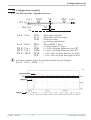
Adjustment:
w The configuration can be adjusted by means of keys ÈÌ .
w Transition to the next configuration is by pressing key Ù .
w After the last configuration of a group, donE is displayed and followed by
automatic change to the next group
Return to the beginning of a group is by pressing the Ù key for 3 sec.
KS 90-1 / KS 92-1
29
Configuration survey
Configuration level
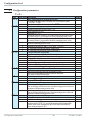
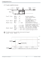
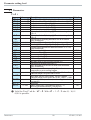
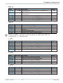
4.2 Configuration parameters
Cntr
Name
SP.Fn
C.tYP
C.Fnc
C.dif
mAn
C.Act
FAIL
Value range Description
Default
0
Basic configuration of setpoint processing
0
set-point controller can be switched over to external set-point
(-> LOGI/ SP.E)
8
standard controller with external offset (SP.E)
0
Calculation of the process value
0
standard controller (process value = x1)
1
ratio controller (x1/x2)
2
difference (x1 - x2)
3
Maximum value of x1and x2. It is controlled with the bigger value.
At sensor failure it is controlled with the remaining actual value.
4
Minimum value of x1and x2. It is controlled with the smaller value.
At sensor failure it is controlled with the remaining actual value.
5
Mean value (x1, x2). With sensor error, controlling is continued
with the remaining process value.
6
Switchover between x1 and x2 (-> LOGI/ I.ChG)
7
O2 function with constant sensor temperature
8
O2 function with measured sensor temperature
1
Control behaviour (algorithm)
0
on/off controller or signaller with one output
1
PID controller (2-point and continuous)
2
∆ / Y / Off, or 2-point controller with partial/full load switch-over
3
2 x PID (3-point and continuous)
4
3-point stepping controller
5
3-point stepping controller with position feedback Yp
6
continuous controller with integrated positioner
0
Output action of the PID controller derivative action
0
Derivative action acts only on the measured value.
1
Derivative action only acts on the control deviation
(set-point is also differentiated)
0
Manual operation permitted
0
no
1
yes (r LOGI / mAn)
0
Method of controller operation
0
inverse, e.g. heating
The correcting variable increases with decreasing process value and
decreases with increasing process value.
1
direct, e.g. cooling
The correcting variable increases with increasing process value and
decreases with decreasing process value.
1
Behaviour at sensor break
0
controller outputs switched off
1
y = Y2
2
y = mean output. The maximum permissible output can be adjusted
with parameter Ym.H. To prevent determination of inadmissible
values, mean value formation is only if the control deviation is
lower than parameter L.Ym.
Configuration parameters
30
KS 90-1 / KS 92-1
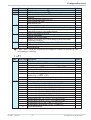
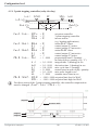
Configuration level
Name
Value range Description
-1999...9999 X0 (start of control range) 1
-1999...9999 X100 (end of control range) 1
Characteristic for 2-point- and 3-point-controllers
0
standard
1
water cooling linear (siehe Seite 44)
2
water cooling non-linear
3
with constant cycle
tunE
Auto-tuning at start-up
0
At start-up with step attempt, at set-point with impulse attempt
1
At start-up and at set-point with impulse attempt. Setting for fast
controlled systems (e.g. hot runner control)
2
Always step attempt at start-up
Strt
Start of auto-tuning
0
Manual start of auto-tuning
1
Manual or automatic start of auto-tuning at power on or when
oscillating is detected
Optimization of T1, T2 (only visible with BlueControl!)
Adt0
0
Automatic optimization
1
No optimization
rnG.L
rnG.H
CYCL
Default
-100
1200
0
0
0
0
1 rnG.L and rnG.H are indicating the range of control on which e.g. the
self-tuning is refering
InP.1
Name
Value range Description
I.fnc
INP1 function selection
0
No function (following INP data are skipped)
1
Heating current input
2
External set-point SP.E (switch-over -> LOGI/ SP.E)
3
Position feedback Yp
4
Second process value x2 (ratio, min, max, mean)
5
External positioning value Y.E
(switch-over r LOGI / Y.E)
6
No controller input (e.g. limit signalling instead)
7
Process value x1
S.tYP
Sensor type selection
0
thermocouple type L (-100...900°C) , Fe-CuNi DIN
1
thermocouple type J (-100...1200°C) , Fe-CuNi
2
thermocouple type K (-100...1350°C), NiCr-Ni
3
thermocouple type N (-100...1300°C), Nicrosil-Nisil
4
thermocouple type S (0...1760°C), PtRh-Pt10%
5
thermocouple type R (0...1760°C), PtRh-Pt13%
6
thermocouple type T (-200...400°C), Cu-CuNi
7
thermocouple type C (0...2315°C), W5%Re-W26%Re
8
thermocouple type D (0...2315°C), W3%Re-W25%Re
9
thermocouple type E (-100...1000°C), NiCr-CuNi
10
thermocouple type B (0/100...1820°C), PtRh-Pt6%
18
special thermocouple
KS 90-1 / KS 92-1
31
Default
7
1
Configuration parameters
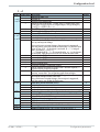
Configuration level
Name
S.Lin
Corr
In.f
fAI1
Value range Description
Default
20
Pt100 (-200.0 ... 100,0 °C)
( -200,0 ... 150,0°C with reduced lead resistance: measuring
resistance + lead resistance ß160 [ )
21
Pt100 (-200.0 ... 850,0 °C)
22
Pt1000 (-200.0 ... 850.0 °C)
23
special 0...4500 Ohm (preset to KTY11-6)
24
special 0...450 Ohm
30
0...20mA / 4...20mA 1
40
0...10V / 2...10V 1
41
special -2,5...115 mV 1
42
special -25...1150 mV 1
50
potentiometer 0...160 Ohm 1
51
potentiometer 0...450 Ohm 1
52
potentiometer 0...1600 Ohm 1
53
potentiometer 0...4500 Ohm 1
0
Linearization (only at S.tYP = 23 (KTY 11-6), 24 (0...450 ), 30
(0..20mA), 40 (0..10V), 41 (0...100mV) and 42 (special -25...1150 mV))
0
none
1
Linearization to specification. Creation of linearization table with
BlueControl (engineering tool) possible. The characteristic for
KTY 11-6 temperature sensors is preset.
0
Measured value correction / scaling
0
Without scaling
1
Offset correction (at CAL level)
(controller offset adjustment is at CALlevel)
2
2-point correction (at CAL level)
(calibration is at the controller CALlevel)
3
Scaling (at PArA level)
4
Autom. calibration (only with positionfeedback Yp)
-1999...9999 Alternative value for error at INP1
OFF
If a value is adjusted, this value is used for display and calculation
in case of error (e.g. FAIL).
a Before activating a substitute value, the effect in the
control loop should be considered!
0
Forcing INP1 (only visible with BlueControl!)
0
No forcing
1
Forcing via serial interface
1 with current and voltage input signals, scaling is required (see chapter 5.3)
InP.2
Name
I.Fnc
Value range Description
Function selection of INP2
0
no function (subsequent input data are skipped)
1
heating current input
2
external set-point (SP.E)
3
Yp input
4
Second process value X2
5
External positioning value Y.E
(switch-over r LOGI / Y.E)
Configuration parameters
32
Default
1
KS 90-1 / KS 92-1
Configuration level
Name
S.tYP
Corr
In.F
fAI2
Value range Description
6
no controller input (e.g. transmitter input instead)
7
Process value x1
Sensor type selection
30
0...20mA / 4...20mA 1
31
0...50mA AC 1
50
Potentiometer ( 0...160 Ohm) 1
51
Potentiometer ( 0...450 Ohm) 1
52
Potentiometer ( 0...1600 Ohm) 1
53
Potentiometer ( 0...4500 Ohm) 1
Measured value correction / scaling
0
Without scaling
1
Offset correction (at CAL level)
(offset entry is at controller CALlevel)
2
2-point correction (at CALlevel)
(calibration is at controller CALlevel)
3
Scaling (at PArA level)
-1999...9999 Alternative value for error at INP2
If a value is adjusted, this value is used for display and calculation
in case of error (e.g. FAIL).
a Before activating a substitute value, the effect in the
control loop should be considered!
Forcing INP2 (only visible with BlueControl!)
0
No forcing
1
Forcing via serial interface
Default
30
0
OFF
0
1 with current and voltage input signals, scaling is required (see chapter 5.3)
InP.3
Name
Value range Description
Default
1
Function selection of INP3
0
no function (subsequent input data are skipped)
1
heating current input
2
External set-point SP.E (switch-over -> LOGI/ SP.E)
3
Yp input
4
Second process value X2
5
External positioning value Y.E
(switch-over r LOGI / Y.E)
6
no controller input (e.g. transmitter input instead)
7
Process value x1
0
S.Lin
Linearization
(only at S.tYP = 30 (0..20mA) and 40 (0..10V) adjustable)
0
none
1
Linearization to specification. Creation of linearization table with
BlueControl (engineering tool) possible. The characteristic for
KTY 11-6 temperature sensors is preset.
30
S.tYP
Sensor type selection
0
thermocouple type L (-100...900°C) , Fe-CuNi DIN
1
thermocouple type J (-100...1200°C) , Fe-CuNi
I.Fnc
KS 90-1 / KS 92-1
33
Configuration parameters
Configuration level
Name
Value range Description
2
thermocouple type K (-100...1350°C), NiCr-Ni
3
thermocouple type N (-100...1300°C), Nicrosil-Nisil
4
thermocouple type S (0...1760°C), PtRh-Pt10%
5
thermocouple type R (0...1760°C), PtRh-Pt13%
6
thermocouple type T (-200...400°C), Cu-CuNi
7
thermocouple type C (0...2315°C), W5%Re-W26%Re
8
thermocouple type D (0...2315°C), W3%Re-W25%Re
9
thermocouple type E (-100...1000°C), NiCr-CuNi
10
thermocouple type B (0/100...1820°C), PtRh-Pt6%
18
special thermocouple
20
Pt100 (-200.0 ... 100,0 °C)
( -200,0 ... 150,0°C with reduced lead resistance: measuring
resistance + lead resistance ß160 [ )
21
Pt100 (-200.0 ... 850,0 °C)
22
Pt1000 (-200.0 ... 850.0 °C)
23
special 0...4500 Ohm (preset to KTY11-6)
24
special 0...450 Ohm
30
0...20mA / 4...20mA 1
41
special -2,5...115 mV 1
42
special -25...115 0mV 1
50
potentiometer 0...160 Ohm 1
51
potentiometer 0...450 Ohm 1
52
potentiometer 0...1600 Ohm 1
53
potentiometer 0...4500 Ohm 1
Corr
Measured value correction / scaling
0
Without scaling
1
Offset correction (at CAL level)
(offset entry is at controller CALlevel)
2
2-point correction (at CAL level)
(calibration is at controller CALlevel)
3
Scaling (at PArA level)
4
Automatic calibration (DAC)
In.F -1999...9999 Alternative value for error at INP3
If a value is adjusted, this value is used for display and calculation
in case of error (e.g. FAIL).
a Before activating a substitute value, the effect in the
control loop should be considered!
Forcing INP3 (only visible with BlueControl!)
fAI3
0
No forcing
1
Forcing via serial interface
Default
0
OFF
0
1 with current and voltage input signals, scaling is required (see chapter 5.3)
Configuration parameters
34
KS 90-1 / KS 92-1
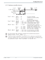
Configuration level
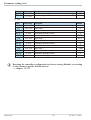
Lim
Name
Fnc.1
Fnc.2
Fnc.3
Src.1
Src.2
Src.3
HC.AL
LP.AL
dAc.A
Hour
Swit
Value range Description
Default
1
Function of limit 1/2/3
0
switched off
1
measured value monitoring
2
Measured value monitoring + alarm latch. A latched limit value
can be reset via error list or via a digital input, or by pressing key
Ò or è (-> LOGI/ Err.r)
3
signal change (change/minute)
4
signal change and storage (change/minute)
1
Source of Limit 1/2/3
0
process value
1
control deviation xw (process value - set-point)
2
Control deviation Xw (=relative alarm) with suppression after
start-up and setpoint change
After switch-on or setpoint change, alarm output is suppressed,
until the process value was within the limits once. At the latest after
elapse of time 10 ti1 the alarm is activated. (ti1 = integral
time 1; parameter r Cntr)
ti1 switched off (ti1 = 0) is considered as Î , i.e. the alarm is
not activated, until the process value was within the limits once.
3
measured value INP1
4
measured value INP2
5
measured value INP3
6
effective setpoint Weff
7
correcting variable y (controller output)
8
control variable deviation xw (actual value - internal setpoint) =
deviation alarm to internal setpoint
9
difference x1 - x2 (utilizable e.g. in combination with process value
function “mean value” for recognizing aged thermocouples
11
Control deviation (=relative alarm) with suppression after start-up
and setpoint change without time limit
After switch-on or setpoint change, alarm output is suppressed,
until the process was within the limits once.
0
Alarm heat current function (INP2)
0
switched off
1
Overload short circuit monitoring
2
Break and short circuit monitoring
0
Monitoring of control loop interruption for heating (see page 68)
0
switched off / inactive
1
active. If ti1=0 LOOP alarm is inactive!
0
DAC alarm function (see page 68)
0
DAC alarm switched off / inactive
1
DAC alarm active
OFF...999999 Operating hours (only visible with BlueControl!)
OFF
OFF...999999 Output switching cycles (only visible with BlueControl !)
OFF
KS 90-1 / KS 92-1
35
Configuration parameters
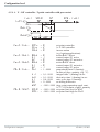
Configuration level
Out.1 and Out.2
Name
O.Act
Y.1
Y.2
Lim.1
Lim.2
Lim.3
dAc.A
LP.AL
HC.AL
HC.SC
FAi.1
FAi.2
FAi.3
dP.Er
fOut
Value range Description
Method of operation of output OUT1
0
direct / normally open
1
inverse / normally closed
Controller output Y1/Y2
0
not active
1
active
Limit 1/2/3 signal
0
not active
1
active
Valve monitoring (DAC)
0
not active
1
active
Interruption alarm signal (LOOP)
0
not active
1
active
Heat current alarm signal
0
not active
1
active
Solid state relay (SSR) short circuit signal
0
not active
1
active
INP1/ INP2 / INP3 error signal
0
not active
1
active
PROFIBUS error
0
not active
1
active: Profibus trouble, no communication with this
instrument.
Forcing OUT1 (only visible with BlueControl!)
0
No forcing
1
Forcing via serial interface
Default
0
1
0
0
0
0
0
0
0
0
Configuration parameters Out.2 = Out.1 except for: Default Y.1 = 0 Y.2 = 1
Out.3
Name
O.tYP
and
Out4
Value range Description
Signal type selection OUT3
0
relay / logic (only visible with current/logic voltage)
1
0 ... 20 mA continuous (only visible with current/logic/voltage)
2
4 ... 20 mA continuous (only visible with current/logic/voltage)
3
0...10 V continuous (only visible with current/logic/voltage)
4
2...10 V continuous (only visible with current/logic/voltage)
5
transmitter supply (only visible without OPTION)
Configuration parameters
36
Default
0
KS 90-1 / KS 92-1
Configuration level
Name
O.Act
Out.0
Out.1
O.Src
O.FAI
Y.1
Y.2
Lim.1
Lim.2
Lim.3
dAc.A
LP.AL
HC.AL
HC.SC
FAi.1
FAi.2
FAi.3
dP.Er
Value range Description
Default
1
Method of operation of output OUT3 (only visible when O.TYP=0)
0
direct / normally open
1
inverse / normally closed
-1999...9999 Scaling of the analog output for 0% (0/4mA or 0/2V, only visible
0
when O.TYP=1..5)
-1999...9999 Scaling of the analog output for 100% (20mA or 10V, only visible
100
when O.TYP=1..5)
1
Signal source of the analog output OUT3 (only visible when
O.TYP=1..5)
0
not used
1
controller output y1 (continuous)
2
controller output y2 (continuous)
3
process value
4
effective set-point Weff
5
control deviation xw (process value - set-point)
6
measured value position feedback Yp
7
measured value INP1
8
measured value INP2
9
measured value INP3
0
Failbehaviour, behaviour of the analog output, if the signal source
(O.Src) is disturbed.
0
upscale
1
downscale
0
Controller output Y1/Y2 (only visible when O.TYP=0)
0
not active
1
active
1
Limit 1/2/3 signal (only visible when O.TYP=0)
0
not active
1
active
0
Valve monitoring (DAC) (only visible when O.TYP=0)
0
not active
1
active
0
Interruption alarm signal (LOOP) (only visible when O.TYP=0)
(Loop-Alarm)
0
not active
1
active
0
Heating current alarm signal (only visible when O.TYP=0)
0
not active
1
active
0
Solid state relay (SSR) short circuit signal (only visible when O.TYP=0)
0
not active
1
active
1
INP1/ INP2 / INP3 error (only visible when O.TYP=0)
0
not active
1
active
0
PROFIBUS error
0
not active
1
active: Profibus trouble, no communication with this instrument.
KS 90-1 / KS 92-1
37
Configuration parameters
Configuration level
Name
Value range Description
Forcing OUT3 (only visible with BlueControl!)
fOut
0
No forcing
1
Forcing via serial interface
Default
0
Out.5/ Out.6
Configuration parameters Out.2 = Out.1 except for: Default Y.1 = 0 Y.2 = 0
g
Method of operation and usage of output Out.1 to Out.6:
Is more than one signal chosen active as source, those signals are OR-linked.
LOGI
Name
Value range Description
L_r
Local / Remote switching (Remote: adjusting of all values by
front keys is blocked)
0
no function (switch-over via interface is possible)
1
always active
2
DI1 switches
3
DI2 switches (basic instrument or OPTION)
4
DI3 switches (only visible with OPTION)
5
è - key switches
SP.2
Switching to second setpoint SP.2
0
no function (switch-over via interface is possible)
2
DI1 switches
3
DI2 switches (only visible with OPTION)
4
DI3 switches (only visible with OPTION)
5
è - key switches
SP.E
Switching to external setpoint SP.E
0
no function (switch-over via interface is possible)
1
always active
2
DI1 switches
3
DI2 switches (only visible with OPTION)
4
DI3 switches (only visible with OPTION)
5
è - key switches
Y2
Y/Y2 switching
0
no function (switch-over via interface is possible)
2
DI1 switches
3
DI2 switches (only visible with OPTION)
4
DI3 switches (only visible with OPTION)
5
è - key switches
6
Ò - key switches
Configuration parameters
38
Default
0
0
0
0
KS 90-1 / KS 92-1
Configuration level
Name
Y.E
mAn
C.oFF
m.Loc
Err.r
Pid.2
Value range Description
Switching to fixed control output Y.E
0
no function (switch-over via interface is possible)
1
always activated (manual station)
2
DI1 switches
3
DI2 switches (only visible with OPTION)
4
DI3 switches (only visible with OPTION)
5
è - key switches
6
Ò - key switches
Automatic/manual switching
0
no function (switch-over via interface is possible)
1
always activated (manual station)
2
DI1 switches
3
DI2 switches (only visible with OPTION)
4
DI3 switches (only visible with OPTION)
5
è - key switches
6
Ò - key switches
Switching off the controller
0
no function (switch-over via interface is possible)
2
DI1 switches
3
DI2 switches (only visible with OPTION)
4
DI3 switches (only visible with OPTION)
5
è - key switches
6
Ò - key switches
Blockage of hand function
0
no function (switch-over via interface is possible)
2
DI1 switches
3
DI2 switches (only visible with OPTION)
4
DI3 switches (only visible with OPTION)
5
è - key switches
Reset of all error list entries
0
no function (switch-over via interface is possible)
2
DI1 switches
3
DI2 switches (only visible with OPTION)
4
DI3 switches (only visible with OPTION)
5
è - key switches
6
Ò - key switches
Switching of parameter set (Pb, ti, td)
0
no function (switch-over via interface is possible)
2
DI1 switches
3
DI2 switches (only visible with OPTION)
4
DI3 switches (only visible with OPTION)
5
è - key switches
KS 90-1 / KS 92-1
39
Default
0
0
0
0
0
0
Configuration parameters
Configuration level
Name
Value range Description
Switching of the actual process value between Inp1 and X2
0
no function (switch-over via interface is possible)
2
DI1 switches
3
DI2 switches (only visible with OPTION)
4
DI3 switches (only visible with OPTION)
5
è - key switches
di.Fn
Function of digital inputs (valid for all inputs)
0
direct
1
inverse
2
toggle key function
Forcing di1/2/3 (only visible with BlueControl!)
fDI1
0
No forcing
fDI2
1
Forcing via serial interface
I.Chg
Default
0
0
0
fDI3
othr
Name
bAud
Addr
PrtY
dELY
dP.AD
bc.up
O2
Unit
dP
Value range Description
Baudrate of the interface (only visible with OPTION)
0
2400 Baud
1
4800 Baud
2
9600 Baud
3
19200 Baud
1...247
Address on the interace (only visible with OPTION)
Data parity on the interface (only visible with OPTION)
0
no parity (2 stop bits)
1
even parity
2
odd parity
3
no parity (1 stopbit)
0...200
Delay of response signal [ms] (only visible with OPTION)
0...126
Profibus address
Behaviour as backup controller (see page )
0
No backup functionality
1
With backup functionality
Entering parameter for O2 in ppm or %
0
Parameter for O2-function in ppm
1
Parameter for O2-function in %
Unit
0
without unit
1
°C
2
°F
Decimal point (max. number of digits behind the decimal point)
0
no digit behind the decimal point
1
1 digit behind the decimal point
2
2 digits behind the decimal point
3
3 digits behind the decimal point
Configuration parameters
40
Default
2
1
1
0
126
0
0
1
0
KS 90-1 / KS 92-1
Configuration level
Name
LED
dISP
C.dEl
FrEq
MAst
CycL
AdrO
AdrU
Numb
ICof
IAda
IExo
ILat
Pass
IPar
ICnf
ICal
Value range Description
Function allocation of status LEDs 1 / 2 / 3 / 4
10
OUT1, OUT2, OUT3, OUT4
11
Heating, alarm 1, alarm 2, alarm 3
12
Heating, cooling, alarm 1, alarm 2
13
Cooling, heating, alarm 1, alarm 2
14
Bus error
0...10
Display luminosity
0..200
Modem delay [ms]
Additional delay time, before the received message is evaluated in
the Modbus. This time is required, unless messages are transferred
continuously during modem transmission.
Switching 50 Hz / 60 Hz (only visible with BlueControl!)
0
50 Hz
1
60 Hz
Modbus master/slave (see page ) (visible only with BlueControl® )
0
No
1
Yes
0...240
Master cycle (sec.) (see page ) (visible only with BlueControl® !)
-32768...3276 Destination address (see page ) (visible only with BlueControl®!)
Default
0
5
0
0
0
120
1100
7
-32768...3276 Source address (see page ) (visible only with BlueControl®!)
7
0...100
Number of data (see page ) (visible only with BlueControl®!)
Block controller off (only visible with BlueControl!)
Released
Blocked
Block auto tuning (only visible with BlueControl!)
0
Released
1
Blocked
Block extended operating level (only visible with BlueControl!)
0
Released
1
Blocked
Suppression error storage (visible only with BlueControl®!)
0
No: error message remain in the error list until
acknowledgement.
1
Yes alarms are deleted from the error list as soon as
corrected
OFF...9999 Password (only visible with BlueControl!)
Block parameter level (only visible with BlueControl!)
0
Released
1
Blocked
Block configuration level (only visible with BlueControl!)
0
Released
1
Block
Block calibration level (only visible with BlueControl!)
0
Released
1
Blocked
KS 90-1 / KS 92-1
1100
1
0
0
1
41
0
0
0
OFF
0
0
0
Configuration parameters
Configuration level
Name
CDis3
TDis3
T.dis3
T.InF1
T.InF2
Value range Description
Default
2
Display 3 controller operating level (only visible with BlueControl!)
0
No value / only text
1
Display of value
2
Output value as bargraph
3
Control deviation as bargraph
4
Process value as bargraph
2...60
10
Display 3 display alternation time [s] (only visible with BlueControl!)
8 Zeichen Text display 3 (only visible with BlueControl!)
8 Zeichen Text Inf.1 (only visible with BlueControl!)
8 Zeichen Text Inf.2 (only visible with BlueControl!)
Lin
Name
(only visible with BlueControl
Description
Linearization for inputs INP1 or INP3
Access to this table is always with selection special
thermocouple for InP.1 or InP.3or with setting S.Lin
= 1: special linearization for linearization. Default: KTY
11-6 (0...4,5 kOhm)
U.LinT
Unit of linearization table
0
No unit
1
In Celsius [°C]
2
In Fahrenheit [°C]
-999.0..99999 Input value 1
In.1
The signal is in [µV] or in [[] dependent of input type
Ou.1 0,001...9999 Output value 1
Signal assigned to In.1
In.2 -999.0..99999 Input value 2
The signal is in [µV] or in [[] dependent of input type
Ou.2 0,001...9999 Output value 2
Signal assigned to In.2
Lin
Value range
:
:
:
:
In.16 -999.0..99999 Input value 16
Ou.16 0,001...9999
:
:
The signal is in [µV] or in [[] dependent of input type
Output value 1 6
Signal assigned to In.16
Default
0
1036
-49,94
1150
-38,94
:
:
4470
150,0
- the engineering tool for the BluePort controller series
+ 3BlueControl
engineering tools with different functionality facilitating the device configu-
ration and parameter setting are available (see chapter 9: Accessory equipment
with ordering information).
In addition to configuration and parameter setting, blue control is used for
data acquisition and offers long-term storage and print functions. Blue control
is connected to the device via the front-panel interface "BluePort" by means
of PC (Windows 95 / 98 / NT) and a PC adaptor.
Description BlueControl: see chapter 8: BlueControl (page 70).
Configuration parameters
42
KS 90-1 / KS 92-1
Configuration level
4.3 Set-point processing
The set-point processing structure is shown in the following picture:
1199
°C
°F
para
func
Ada
Err
1200
SP.E SP.2
Xeff
Internal
set-point
Ü
SP.Hi
0
+
External
set-point SP.E
INP2
8 *
SP.Lo
Limitation
Ü
0/4...20 mA
Ö
Effektive
r.SP set-point
2. set-point SP.2
- LED
Ramp
Index:
Ü : int/ext-setpoint switching
* : configuration SP.Fn
Ö : SP / SP.2 switching
The ramp starts at process value
with the following switchings:
- int / ext-setpoint switching
- SP / SP.2switching
- Manual-/ Automatic switching
- at power on
4.3.1 Set-point gradient / ramp
To prevent setpoint step changes, a maximum rate of change is adjustable for
parameter r setpoint r r.SP. This gradient acts both in positive and negative
direction.
With parameter r.SP set to OFFas in the factory setting, the gradient is
switched off and setpoint changes are made directly.
KS 90-1 / KS 92-1
43
Set-point processing
Configuration level
4.4 Switching behaviuor
With these controllers, configuration parameter CYCL (ConF/ Cntr/ CYCL)
can be used for matching the cycle time of 2-point and 3-point controllers. This
can be done using the following 4 methods.
4.4.1 Standard ( CyCl= 0 )
The adjusted cycle times t1 and t2 are valid for 50% or -50% correcting variable. With very small or very high values, the effective cycle time is extended to
prevent unreasonably short on and off pulses. The shortest pulses result from ¼ x
t1 or ¼ x t2. The characteristic curve is also called “bath tub curve”
T / T1
6,0
relative cycle duration
5,0
4,0
4 x t1
3,0
3 x t1
2,0
2 x t1
1,0
t1
0,0
5
10
15
20
25
30
35
40
45
50
55
60
65
70
75
80
85
90
95
Controller output [%]
Parameters to be adjusted:
( PArA/ Cntr)
t1 : min. cycle time 1 (heating) [s]
t2 : min. cycle time 2 (cooling) [s]
4.4.2 Switching attitude linear ( CyCl= 1 )
For heating (Y1), the standard method (see chapter 4.4.1) is used. For cooling
(Y2), a special algorithm for cooling with water is used. Generally, cooling is enabled only at an adjustable process temperature (E.H2O), because low temperatures prevent evaporation with related cooling, whereby damage to the plant is
avoided. The cooling pulse length is adjustable using parameter t.on and is fixed for all output values.
The “off” time is varied dependent of output value. Parameter t.off is used for
determining the min “off” time. For output of a shorter off pulse, this pulse is
suppressed, i.e. the max. effective cooling output value is calculated according to
formula t.on / ( t.on + t.off) w 100%.
Parameters to be adjusted: E.H2O: minimum temperature for water cooling
( PArA / Cntr)
t.on: pulse duration water cooling
t.off: minimum pause water cooling
Switching behaviuor
44
KS 90-1 / KS 92-1
Configuration level
70
-95%
-67%
-80%
-100%
-92%
Parameter:
t.on = 0.4 sec
t.off = 0.2 sec
60
Effective controller output
-90%
-87%
-82%
4.4.3 Switching attitude non-linear ( CyCl= 2 )
With this method, the cooling power is nort.on
t.off
mally much higher than the heating power,
i.e. the effect on the behaviour during transition from heating to cooling may be negative. The cooling curve ensures that the
control intervention with 0 to -70% correcting variable is very weak. Moreover, the
correcting variable increases very quickly to max. possible cooling. Parameter F.H2O can
be used for changing the characteristic curve. The standard method (see section 4.4.1) is
also used for heating. Cooling is also enabled dependent of process temperature .
50
40
Water cooling non-linear, F.H2O=1
Water cooling non-linear, F.H2O=2
Water cooling non-linear, F.H2O=0,5
Water cooling linear
30
20
10
0
-100
-95
-90
-85
-80
-75
-70
-65
-60
-55
-50
-45
-40
-35
-30
-25
-20
-15
-10
-5
Controller output [%]
Parameters to be adjusted:
( PArA / Cntr)
KS 90-1 / KS 92-1
45
F.H2O: adaptation of (non-linear) characteristic
Water cooling
t.on: Pulse duration water cooling
t.off: min. pause water cooling
E.H2O: min. temperature for water cooling
Switching behaviuor
Configuration level
4.4.4 Heating and cooling with constant period ( CyCl= 3 )
1 and t2 are met in the overall output
tp
range . To prevent unreasonably short
t1/ t2
pulses, parameter tp is used for adjusting the shortest pulse duration. With
50%
30%
small correcting values which require a
pulse shorter than the value adjusted in
tp
tp, this pulse is suppressed. However,
t1/ t2
the controller stores the pulse and totalizes further pulses, until a pulse of duration tp can be output.
50%
Parameters to be adjusted:
( PArA/ Cntr)
Switching behaviuor
70%
20%
10%
80%
90%
t1 : Min. cycle time 1 (heating) [s]
t2 : min. cycle time 2 (cooling) [s]
tp: min. pulse length [s]
46
KS 90-1 / KS 92-1
Configuration level
4.5 Configuration examples
4.5.1 On-Off controller / Signaller (inverse)
InL.1
SP.LO
SP
SP.Hi InH.1
InP.1Ê
100%
SH
Out.1Â
0%
ConF / Cntr:
SP.Fn
C.Fnc
C.Act
ConF / Out.1:
O.Act
Y.1
Hys.l
Hys.H
SP.LO
SP.Hi
PArA / Cntr:
PArA / Cntr:
PArA / SEtP:
g
= 0set-point controller
= 0signaller with one output
= 0inverse action
(e.g. heating applications)
= 0action Out.1 direct
=1control output Y1 active
= 0...9999 switching difference below SP
= 0...9999 switching difference above SP
= -1999...9999 set-point limit low for Weff
= -1999...9999 set-point limit high for Weff
For direct signaller action, the controller action must be changed
(ConF / Cntr / C.Act = 1 )
process value
SH
setpoint
output
KS 90-1 / KS 92-1
47
Configuration examples
Configuration level
4.5.2 2-point controller (inverse)
InL.1
SP.LO
InP.1Ê
SP
SP.Hi InH.1
PB1
100%
Out.1Â
0%
ConF / Cntr:
SP.Fn
C.Fnc
C.Act
ConF / Out.1:
O.Act
Y.1
Pb1
PArA / Cntr:
PArA / SEtP:
g
ti1
td1
t1
SP.LO
SP.Hi
= 0
= 1
= 0
set-point controller
2-point controller (PID)
inverse action
(e.g. heating applications)
= 0
action Out.1 direct
= 1
control output Y1 active
= 1...9999
proportional band 1 (heating)
in units of phys. quantity (e.g. °C)
= 0,1...9999
integral time 1 (heating) in sec.
= 0,1...9999
derivative time 1 (heating) in sec.
= 0,4...9999
min. cycle time 1 (heating)
= -1999...9999 set-point limit low for Weff
= -1999...9999 set-point limit high for Weff
For direct action, the controller action must be changed
(ConF / Cntr / C.Act = 1 ).
setpoint
process value
output
Configuration examples
48
KS 90-1 / KS 92-1
Configuration level
4.5.3 3-point controller (relay & relay)
SP.LO
InL.1
InP.1Ê
SP
PB1
100%
Out.1Â
SP.Fn
C.Fnc
C.Act
ConF / Out.1:
O.Act
Y.1
Y.2
O.Act
Y.1
Y.2
Pb1
Pb2
PArA / SEtP:
KS 90-1 / KS 92-1
100%
0%
ConF / Cntr:
PArA / Cntr:
PB2
Out.2Â
0%
ConF / Out.2:
SP.Hi InH.1
ti1
ti2
td1
td2
t1
t2
SH
SP.LO
SP.Hi
49
= 0
= 3
= 0
set-point controller
3-point controller (2xPID)
action inverse
(e.g. heating applications)
= 0
action Out.1 direct
= 1
control output Y1 active
= 0
control output Y2 not active
= 0
action Out.2 direct
= 0
control output Y1 not active
= 1
control output Y2 active
= 1...9999
proportional band 1 (heating)
in units of phys. quantity (e.g. °C)
= 1...9999
proportional band 2 (cooling)
in units of phys. quantity (e.g. °C)
= 0,1...9999
integral time 1 (heating) in sec.
= 0,1...9999
derivative time 2 (cooling) in sec.
= 0,1...9999
integral time 1 (heating) in sec.
= 0,1...9999
derivative time 2 (cooling) in sec.
= 0,4...9999
min. cycle time 1 (heating)
= 0,4...9999
min. cycle time 2 (cooling)
= 0...9999
neutr. zone in units of phys.quantity
= -1999...9999 set-point limit low for Weff
= -1999...9999 set-point limit high for Weff
Configuration examples
Configuration level
4.5.4 3-point stepping controller (relay & relay)
InL.1
SP.LO
InP.1Ê
SP
PB1
100%
Out.1Â
SP.Hi InH.1
100%
SH
Out.2Â
0%
ConF / Cntr:
SP.Fn
C.Fnc
C.Act
= 0
= 4
= 0
ConF / Out.1:
O.Act
Y.1
Y.2
O.Act
Y.1
Y.2
Pb1
=
=
=
=
=
=
=
ti1
td1
t1
SH
tP
tt
SP.LO
SP.Hi
=
=
=
=
=
=
=
=
ConF / Out.2:
PArA / Cntr:
PArA / SEtP:
g
0%
set-point controller
3-point stepping controller
inverse action
(e.g. heating applications)
0
action Out.1 direct
1
control output Y1 active
0
control output Y2 not active
0
action Out.2 direct
0
control output Y1 not active
1
control output Y2 active
1...9999
proportional band 1 (heating)
in units of phys. quantity (e.g. °C)
0,1...9999 integral time 1 (heating) in sec.
0,1...9999 derivative time 1 (heating) in sec.
0,4...9999 min. cycle time 1 (heating)
0...9999
neutral zone in units of phy. quantity
0,1...9999 min. pulse length in sec.
3...9999
actuator travel time in sec.
-1999...9999 set-point limit low for Weff
-1999...9999 set-point limit high for Weff
For direct action of the 3-point stepping controller, the controller output action
must be changed ( ConF / Cntr / C.Act = 1 ).
setpoint
process value
output 1
output 2
Configuration examples
50
KS 90-1 / KS 92-1
Configuration level
4.5.5 Continuous controller (inverse)
SP.LO
InL.1
InP.1Ê
SP
SP.Hi InH.1
PB1
20 mA
Out.3Â
0/4 mA
ConF / Cntr:
SP.Fn
C.Fnc
C.Act
= 0
= 1
= 0
ConF / Out.3:
O.tYP
Out.0
Out.1
Pb1
=
=
=
=
1/2
-1999...9999
-1999...9999
1...9999
ti1
td1
t1
SP.LO
SP.Hi
=
=
=
=
=
0,1...9999
0,1...9999
0,4...9999
-1999...9999
-1999...9999
PArA / Cntr:
PArA / SEtP:
g
g
set-point controller
continuous controller (PID)
inverse action
(e.g. heating applications)
Out.3 type ( 0/4 … 20mA )
scaling analog output 0/4mA
scaling analog output 20mA
proportional band 1 (heating)
in units of phys. quantity (e.g. °C)
integral time 1 (heating) in sec.
derivative time 1 (heating) in sec.
min. cycle time 1 (heating)
set-point limit low for Weff
set-point limit high for Weff
For direct action of the continuous controller, the controller action must be
changed ( ConF / Cntr / C.Act = 1 ).
To prevent control outputs Out.1 and Out.2 of the continuous controller from
switching simultaneously, the control function of outputs Out.1 and Out.2 must
be switched off ( ConF / Out.1 and Out.2 / Y.1 and Y.2 = 0 ).
KS 90-1 / KS 92-1
51
Configuration examples
Configuration level
4.5.6 ∆ - Y - Off controller / 2-point controller with pre-contact
InL.1
SP.LO
SP
InP.1Ê
SP.Hi InH.1
PB1
100%
Out.1Â
0%
Out.2Â
SH
ConF / Cntr:
SP.Fn
C.Fnc
C.Act
ConF / Out.1:
O.Act
Y.1
Y.2
O.Act
Y.1
Y.2
Pb1
ConF / Out.2:
PArA / Cntr:
ti1
td1
t1
SH
d.SP
PArA / SEtP:
Configuration examples
SP.LO
SP.Hi
d.SP
= 0
= 2
= 0
set-point controller
∆ -Y-Off controller
inverse action
(e.g. heating applications)
= 0
action Out.1 direct
= 1
control output Y1 active
= 0
control output Y2 not active
= 0
action Out.2 direct
= 0
control output Y1 not active
= 1
control output Y2 active
= 1...9999
proportional band 1 (heating)
in units of phys. quantity (e.g. °C)
= 0,1...9999
integral time 1 (heating) in sec.
= 0,1...9999
derivative time 1 (heating) in sec.
= 0,4...9999
min. cycle time 1 (heating)
= 0...9999
switching difference
= -1999...9999 trigg. point separation suppl. cont.
∆ / Y / Off in units of phys. quantity
= -1999...9999 set-point limit low for Weff
= -1999...9999 set-point limit high for Weff
52
KS 90-1 / KS 92-1
Configuration level
4.5.7 Continuous controller with position controller
( Cntr/ C.Fnc = 6 )
SP
W
INP.1
X
Ycontinuous
Ypid
OUT.4
Master controller
W
Y.1
INP.2
X
OUT.1
M
Y.2
OUT.2
Position controller
Basically, this controller function is a cascade. A slave controller with three-point
stepping behaviour working with position feedback Yp as process value (INP2 or
INP3) is added to a continuous controller.
ConF / Cntr SP.Fn = 0
setpoint controller
C.Fnc = 6
continuous controller with
position controller
C.Act = 0
inverse output action
(e.g. heating applications)
ConF / InP.2:
I.Fnc
S.typ
= 3
= 50
position feedback Yp
sensor e.g. potentiometer 0..160 Ω
ConF / Out.1:
O.Act
Y.1
Y.2
= 0
= 1
= 0
direct output action Out.1
control output Y1 active
control output Y2 not active
ConF / Out.2:
O.Act
Y.1
Y.2
= 0
= 0
= 1
direct output action Out.2
control output Y1 not active
control output Y2 active
PArA / Cntr:
Pb1
= 0,1...9999
ti1
td1
t1
SH
=
=
=
=
proportional band 1 (heating)
in units of the physical quantity
(e.g. °C)
integral time 1 (heating) in sec.
derivative time 1 (heating) in sec.
min. cycle tim 1 (heating)
switching difference
KS 90-1 / KS 92-1
53
1...9999
1...9999
0,4...9999
0...9999
Configuration examples
Configuration level
4.5.8 Measured value output
phys.
quantity
Out.1
mA / V
phys. quantity
Out.0
20mA
10V
0/4mA
0/2V
90...250VAC
24VUC
} NL
1
2
1
2
3
3
4
5
6
7
8
9
OUT3
OUT4
10
11
12
U
13
14
15
4
5
6
7
8
9
10
11
12
13
14
U
15
(16)
INP1
17 +
ConF / Out.3 / 4: O.tYP =
=
=
=
Out.0 =
1
2
3
4
-1999...9999
Out.1 =
-1999...9999
O.Src =
3
Configuration examples
54
Out.3/ 4 0...20mA continuous
Out.3/ 4 4...20mA continuous
Out.3/ 4 0...10V continuous
Out.3/ 4 2...10V continuous
scaling Out.3/ 4
for 0/4mA or 0/2V
scaling Out.3/ 4
for 20mA or 10V
signal source for Out.3/ 4 is
the process value
KS 90-1 / KS 92-1
Parameter setting level
5 Parameter setting level
5.1 Parameter survey
g
Inl.2
OuL.2
InH.2
OuH.2
tF.2
InL.3
OuL.3
InH.3
OuH.3
tF.3
E.tc
End
InL.1
OuL.1
InH.1
OuH.1
tF.1
Lim
Limit value functions
Input 3
Input 2
InP.3
SP.Lo
SP.Hi
SP.2
r.SP
Input 1
SEtP Set-point and
process value
PAr.2
Pb12
Pb22
ti12
ti22
td12
td22
InP.2
Pb1
Pb2
ti1
ti2
td1
td2
t1
t2
SH
Hys.l
Hys.H
d.SP
tP
tt
Y.Lo
Y.Hi
Y2
Y0
Ym.H
L.Ym
E.H2O
t.on
t.off
FH2
oFFS
tEmp
InP.1
Ì
2. set of parameters
È
Cntr Control and
self-tuning
PArA Parameter setting level
L.1
H.1
HYS.1
dEl.1
L.2
E.tc H.2
HYS.2
dEl.2
L.3
H.3
HYS.3
dEl.3
HC.A
Adjustment:
w The parameters can be adjusted by means of keys ÈÌ
w Transition to the next parameter is by pressing key Ù
w After the last parameter of a group, donE is displayed, followed by
automatic change to the next group.
Return to the beginning of a group is by pressing the Ù key for 3 sec.
If for 30 sec. no keypress is excecuted the controler returns to the process value and setpoint display ( Time Out = 30 sec. )
KS 90-1 / KS 92-1
55
Parameter survey
Parameter setting level
5.2 Parameters
Cntr
Name
Pb1
Pb2
ti1
ti2
td1
td2
t1
t2
SH
Hys.l
Hys.H
d.SP
tP
tt
Y.Lo
Y.Hi
Y2
Y.0
Ym.H
L.Ym
E.H2O
t.on
t.oFF
F.H2O
oFFS
tEmp
Value range Description
Default
1...9999 1 Proportional band 1 (heating) in phys. dimensions (e.g. °C)
100
1...9999 1 Proportional band 2 (cooling) in phys. dimensions (e.g. °C)
100
0,1...9999 Integral action time 1 (heating) [s]
180
0,1...9999 Integral action time 2 (cooling) [s]
180
0,1...9999 Derivative action time 1 (heating) [s]
180
0,1...9999 Derivative action time 2 (cooling) [s]
180
0,4...9999 Minimal cycle time 1 (heating) [s]. The minimum impulse is
10
1/4 x t1
0,4...9999 Minimal cycle time 2 (heating) [s]. The minimum impulse is
10
1/4 x t2
0...9999
2
Neutral zone or switching differential for on-off control
[phys. dimensions)
0...9999
1
Switching difference Low signaller [engineering unit]
0...9999
1
Switching difference High signaller [engineering unit]
-1999...9999 Trigger point seperation for additional contact ∆ / Y / Off
100
[phys. dimensions]
0,1...9999 Minimum impulse [s]
OFF
3...9999
60
Motor travel time [s]
-120...120 Lower output limit [%]
0
-120...120 Upper output limit [%]
100
-100...100 2. correcting variable
0
-100...100 Working point for the correcting variable [%]
0
-100...100 Limitation of the mean value Ym [%]
5
0...9999
8
Max. deviation xw at the start of mean value calculation
[phys. dimensions]
-1999...9999 Min. temperature for water cooling. Below the set
0
temperature no water cooling happens
0,1...9999 Impulse lenght for water cooling. Fixed for all values of
1
controller output.The pause time is varied.
1...9999
10
Min. pause time for water cooling. The max. effective
controller output results from t.on/(t.on+t.off)·100%
0,1...9999 Modification of the (non-linear) water cooling characteristic
1
(see page 45)
-120...120 Zero offset
0
0...9999
750
Sensor temperature (in engineering units e.g. °C)
With oxygen measurement (O2) (see page 65)
1 Valid for ConF/ othr/ dP = 0. With dP = 1 / 2 / 3 also 0,1 / 0,01 /
0,001 is possible.
Parameters
56
KS 90-1 / KS 92-1
Parameter setting level
PAr.2
Name
Pb12
Pb22
Ti22
Ti12
Td12
Td22
Value range Description
Default
1...9999 1 Proportional band 1 (heating) in phys. dimensions (e.g. °C),
100
2. parameter set
1...9999 1 Proportional band 2 (cooling) in phys. dimensions (e.g. °C),
100
2. parameter set
0,1...9999 Integral action time 2 (cooling) [s], 2. parameter set
10
0,1...9999 Integral action time 1 (heating) [s], 2. parameter set
10
0,1...9999 Derivative action time 1 (heating) [s], 2. parameter set
10
0,1...9999 Derivative action time 2 (cooling) [s], 2. parameter set
10
SEtP
Name
SP.LO
SP.Hi
SP.2
r.SP
SP
g
Value range Description
-1999...9999 Set-point limit low for Weff
-1999...9999 Set-point limit high for Weff
-1999...9999 Set-point 2.
0...9999
Set-point gradient [/min]
-1999...9999 Set-point (only visible with BlueControl!)
Default
0
900
0
OFF
0
SP.LO and SP.Hi should be within the limits of rnGH and rnGL see
configuration r Controller page
InP.1
Name
InL.1
OuL.1
InH.1
OuH.1
t.F1
Etc.1
Value range Description
-1999...9999 Input value for the lower scaling point
-1999...9999 Displayed value for the lower scaling point
-1999...9999 Input value for the upper scaling point
-1999...9999 Displayed value for the lower scaling point
0,0...9999 Filter time constant [s]
0...100 (°C) External cold-junction reference temperature (external TC)
Default
Value range Description
-1999...9999 Input value for the lower scaling point
-1999...9999 Displayed value for the lower scaling point
-1999...9999 Input value for the upper scaling point
-1999...9999 Displayed value for the upper scaling point
0,0...9999 Filter time constant [s]
Default
Value range Description
-1999...9999 Input value for the lower scaling point
-1999...9999 Displayed value for the lower scaling point
-1999...9999 Input value for the upper scaling point
-1999...9999 Displayed value for the upper scaling point
Default
32...212 (°F)
0
0
20
20
0,5
OFF
InP.2
Name
InL.2
OuL.2
InH.2
OuH.2
t.F2
0
0
50
50
0,5
InP.3
Name
InL.3
OuL.3
InH.3
OuH.3
KS 90-1 / KS 92-1
57
0
0
20
20
Parameters
Parameter setting level
Name
Value range Description
-1999...9999 Filter time constant [s]
t.F3
0...100 (°C) External cold-junction reference temperature (external TC)
Etc.3
32...212 (°F
Default
0
OFF
Lim
Name
L.1
H.1
HYS.1
dEl.1
L.2
H.2
HYS.2
dEl.2
L.3
H.3
HYS.3
dEl.3
HC.A
g
Parameters
Value range Description
-1999...9999 Lower limit 1
-1999...9999 Upper limit 1
0...9999
Hysteresis limit 1
0...9999
Alarm delay from limit value 1
-1999...9999 Lower limit 2
-1999...9999 Upper limit 2
0...9999
Hysteresis limit 2
0...9999
Alarm delay from limit value 2
-1999...9999 Lower limit 3
-1999...9999 Upper limit 3
0...9999
Hysteresis limit 3
0...9999
Alarm delay from limit value 3
-1999...9999 Heat current limit [A]
Default
10
10
1
0
OFF
OFF
1
0
OFF
-32000
1
0
50
Resetting the controller configuration to factory setting (Default) or resetting
to the customer-specific default data set
r chapter 11.179
58
KS 90-1 / KS 92-1
Parameter setting level
5.3 Input scaling
When using current, voltage or resistance signals as input variables for InP.1,
InP.2 or/and InP.3 scaling of input and display values at parameter setting level
is required. Specification of the input value for lower and higher scaling point is
in the relevant electrical unit (mA / V / Ω).
phys.
quantity
OuH.x
phys. quantity
mA / V
OuL.x
InL.x
InH.x mA/V
5.3.1 Input Inp.1 and InP.3
g
Parameters InL.x , OuL.x, InH.x and OuH.x are only visible if
ConF / InP.x / Corr = 3 is chosen.
S.tYP
30
(0...20mA)
40
(0...10V)
a
Input signal
0 … 20 mA
4 … 20 mA
0 … 10 V
2 … 10 V
InL.x
0
4
0
2
OuL.x
any
any
any
any
InH.x
20
20
10
10
OuH.x
any
any
any
any
In addition to these settings, InL.x and InH.x can be adjusted in the range
(0...20mA / 0...10V / Ω) determined by selection of S.tYP .
For using the predetermined scaling with thermocouple and resistance
thermometer (Pt100), the settings for InL.x and OuL.x and for InH.x and
OuH.x must have the same value.
g
Input scaling changes at calibration level (r page 60) are displayed by input
scaling at parameter setting level. After calibration reset (OFF), the scaling
parameters are reset to default.
5.3.2 Input InP.2
S.tYP
30
31
Input signal
0 … 20 mA
0 … 50 mA
InL.2
0
0
OuL.2
any
any
InH.2
20
50
OuH.2
any
any
In addition to these settings, InL.2 and InH.2 can be adjusted in the range
(0...20/ 50mA/Ω) determined by selection of S.tYP.
KS 90-1 / KS 92-1
59
Input scaling
Calibration level
6 Calibration level
Measured value correction ( CAL) is only visible if ConF / InP.1 / Corr = 1
or 2 is chosen.
The measured value can be matched in the calibration menu ( CAL). Two methods are available:
Offset correction
( ConF/ InP.1 / Corr =1 ):
display
standard setting
offset correction
w possible on-line at the
process
OuL.1new
OuL.1old
InL.1
X
2-point correction
( ConF/ InP.1 / Corr = 2 ):
display
standard setting
2-point correction
w is possible off-line with
process value simulator
OuH.1old
OuH.1new
OuL.1new
OuL.1old
InL.1
60
InH.1
X
KS 90-1 / KS 92-1
Calibration level
Offset correction ( ConF/ InP.1 / Corr =1 ):
r
1199
°C
°F
para
func
Ada
Err
1200
r Ù r PArA
3 sec.
Ì
:
SP.E SP.2
CAL r Ù
r InP.1 r Ù r InL.1 r Ù
r OuL.1 È r Ù
Ì
r End r Ù
InL.1: The input value of the scaling point is displayed.
The operator must wait, until the process is at rest.
Subsequently, the operator acknowledges the input value by pressing
key Ù.
OuL.1: The display value of the scaling point is displayed.
Before calibration, OuL.1 is equal to InL.1.
The operator can correct the display value by pressing keys ÈÌ .
Subsequently, he confirms the display value by pressing key Ù.
KS 90-1 / KS 92-1
61
Calibration level
2-point correction ( ConF/ InP.1 / Corr = 2):
1199
°C
°F
1200 r Ù r
3 sec.
SP.E SP.2
PArA
Ì
r
para
func
Ada
Err
ConF
r
Ì
CAL
r Ùr InP.1 r Ù r InL.1 r Ù
È
È
Ì
InL1
InP.2
OuL.1
Ù
È
Ì
È
rÙ
Ì
InH.1 r
InP.3
Ù
È
InH.1
È
Ì
Ù
OuH.1
Ù End
È
rÙ
Ì
InL.1: The input value of the lower scaling point is displayed.
The operator must adjust the lower input value by means of a
process value simulator and confirm the input value by pressing key Ù.
OuL.1: The display value of the lower scaling point is displayed.
Before calibration, OuL.1 equals InL.1.
The operator can correct the lower display value by pressing the ÈÌ
keys. Subsequently, he confirms the display value by pressing key Ù.
InH.1: The input value of the upper scaling point is displayed. .
The operator must adjust the upper input value by means of the
process value simulator and confirm the input value by pressing key Ù.
OuH.1: The display value of the upper scaling point is displayed.
Before calibration OuH.1 equals InH.1.
The operator can correct the upper display value by pressing keys ÈÌ
Subsequently, he confirms the display value by pressing key Ù.
g
The parameters (OuL.1, OuH.1) changed at CAL level can be reset by adjusting
the parameters below the lowest adjustment value (OFF) by means of decrement
key Ì .
62
KS 90-1 / KS 92-1
Special functions
7 Special functions
7.1 DAC®– motor actuator monitoring
(Digital Actor Control DAC®)
With all controllers with position feedback Yp, the motor actuator can be monitored for functional troubles. The DAC® function can be started by chosing the parameter C.Fnc = 5 or 6 at the configuration level ( ConF):
w ConF / Cntr / C.Fnc = 5
3-point-stepping controller with
position feedback Yp as potentiometer
w ConF / Cntr / C.Fnc = 6
Continuous controller with integrated
positioner and position feedback Yp as
potentiometer
If an error occures, the controller switches to manual operation (ò - LED blinks)
and no impulses are given out any longer. If one of the relays shall switch when a
DAC® error occures, parameter dAC.A = 1 and inverse action O.Act = 1 must
be selected for the relevant output OUT.1 … OUT.4 in the ConF menu
( OUt.3 and 4 only possible if O.tYP = 0 [relay/logic]):
w ConF / OUt.x / dAc.A = 1
Motor actuator monitoring (DAC) aktive
The system detects the following stepping controller errors:
w defective motor
w defective capacitor (wrong rotating direction)
w wrong phase followers (wrong rotating direction)
w defective force transmission at spindle or drive
w excessive backlash due to wear
w jamming of the control valve e.g. due to foreign body
In these cases the controller will change to manual operation and the outputs will
be switched off. Is the controller switched to automatic operation again or any
modification is done the controller activates the DAC function again and the outputs will be setted.
Resetting of a DAC error:
After solving the technical problem the DAC errror can be acknowledged in the
error list. Thereafter the controller works again in normal operation mode.
See also chapter 3.4 "Mainenance manager / Error list", page 12 ff.
KS 90-1 / KS 92-1
63
DAC – motor actuator monitoring
®
Special functions
Functioning of the DAC function
No input filter should be defined for the Yp input ( PArA / InP.x / t.Fx = 0 ).
Therewith no wrong detection of blocking or wrong method of operation can be
recognized.
The automatic calibration can be used with drives outfitted with spring assembly.
Execution of the calibration:
It is controlled if the mean alteration between two messurements is enough for
the DAC monitoring. The calibration will be stopped if the alteration between
two messurements is too small.
The position of 0% is searched. Therefor the drive will be closed until there is no
changing of the input signal for 0,5 sec.
Assuming that the drive is outfitted with spring assembly, the drive is opened for
2,8 sec. The drive should then still be within the spring assembly. This position is
allocated and stored as 0%.
With the same procedure the position for 100% is allocated and stored.
Simultaneously the motor running time is determined and saved as parameter tt.
Afterwards the controller sets the drive in the position before calibration.
Was the controller in automatic mode before calibration it will be set to automatic
mode again otherwise it remains in manual mode.
The following errors can be occure during calibration:
w the change of the Yp input is to small, no monitoring is possible
w the motion is in wrong direction
w the Yp input is broken
In these cases the automatic calibration will be stopped and the controller remains
in manual mode.
g
If the automatic calibration leads to no resonable results the calibration of the Yp
input can be done manual.
g
If the conroller reaches the positions of 0% or 100% the outputs will be switched
off. Also in manual mode it is not possible to exceed these limits.
g
Because no controller with continuouse output and Yp input is defined there
won't be the DAC function for this controlling type.
DAC – motor actuator monitoring
®
64
KS 90-1 / KS 92-1
Special functions
7.2 O2 measurement
This function is available only on the instrument version with INP3.
As the O2-measurement result range can extend over many decades, automatic
display switch-over between “ % ” and “ppm“ was realized.
The instantaneous unit is displayed in
the lower line.
With set-point changing via keys I or
D, the unit of the set-point and of the
other parameters is displayed.
Lambda probes (λ probes) are used as
sensors.
The electromotive force (in Volts) generated by λ probes is dependent of instantaneous oxygen content and temperature. Therefore, KS 90-1 can only evaluate
exact measurement results, if it knows the sensor temperature.
Distinction of heated and non-heated lambda probes is made. Both can be evaluated by KS 90-1.
Heated lambda probes
Controlled heating which ensures constant temperature is integrated in the heated
λ probe. This temperature must be entered in KS 90-1 parameter Probe temperature.
Parameter r Controller r Probe temperature r .....°C (/°F - dependent of configuration)
Cntr r tEmP
temp.
0...9999
Non-heated lambda probes
With the probe always operated at a fixed, known temperature, a procedure as
used for a heated probe can be used.
A non-heated λ probe is used, unless the temperature is constant. In this case, the
probe temperature in addition to the probe mV value must be measured. For this
purpose, any temperature measurement with one of the analog inputs INP2 or
INP3 can be used. During function selection, the input must be set to X2 (second
process value).
7.2.1 Connection
Connect the input for the lambda probe to INP1.
Use terminals A15 and A17.
If necessary, temperature measurement must be connected to INP2 or INP3.
KS 90-1 / KS 92-1
65
O measurement
2
Special functions
7.2.2 Configuration:
Oxygen measurement
Oxygen measurement with heated lambda probe
Controller r Process value processing r 7: O2 functions with constant probe
temperature
Cntr r C.tYP
7
O2-const
Oxygen measurement with non-heated lambda probe
Controller r Process value processing r O2 functions with measured probe
temperature
Cntr r C.tYP
8
O2+temp
Input 1 r Function INP1 r 7: process value X1
InP.1 r 1.Fnc
7
X1-Input
In input 1, the sensor type is set for one of the high-impedance voltage inputs:
Input 1 r Sensor type r 42: special (-25...1150 mV) or
41: special (-2,5...115 mV)
InP.1 r S.tyP
InP.1 r S.tyP
41
42
115 mV
1150 mV
Input 1 r meas. value correction r 0: no correction
InP.1 r S.Lin
0
no
Temperature measurement (required with non-heated lambda probe)
Any temperature measurement with one of analog inputs INP2 or INP3 can be
used. Select input X2 during function selection (second set-point).
g
With O2 measurement, evaluation in ppm or % must be specified for all
parameters related to the process value.
This is done centrally during configuration.
Other r Parameter unit for O2r 0: parameter for O2 function in ppm
1: parameter for O2 function in %
othrr O2
othrr O2
g
unit : ppm
unit : %
Whether the temperature of the non-heated λ probe is specified in °C or °F can
be selected during configuration.
Other r Unit r 1: in Celsius
2: in Fahrenheit
othrr Unit
othrr Unit
O measurement
2
0
1
1
2
°C
°F
66
KS 90-1 / KS 92-1
Special functions
7.3 Linearization
Linearization for inputs INP1 or INP3
Access to table “ Lin” is always with selection of sensor type S.TYP = 18:
special thermocouple in INP1 or INP3, or with selection of linearization S.Lin
1: special linearization.
Dependent of input type, the input signals are specified in µV or in Ohm
dependent of input type.
With up to 16 segment points, non-linear signals can be simulated or linearized.
Every segment point comprises an input (In.1 … In.16) and an output (Ou.1
… Ou.16). These segment points are interconnected automatically by means of
straight lines. The straight line between the first two segments is extended
downwards and the straight line between the two largest segments is extended
upwards. I.e. a defined output value is also provided for each input value.
When switching an In.x value to OFF, all other ones are switched off.
Condition for these configuration parameters is an ascending order.
In.1 < In.2 < ...< In.16 and Ou.1 < Ou.2 ...< Ou.16.
In.16
.
.
.
.
.
.
In 1
Ou.1.....................Ou.16
KS 90-1 / KS 92-1
67
Linearization
Special functions
7.4 Loop alarm
The loop alarm monitors the control loop for interruption
(not with three-point stepping controller and not with signallers.)
With parameter LP.AL switched to 1(= loop alarm active), an interruption of
the control loop is detected, unless the process value reacts accordingly with
Y=100% after elapse of 2xTi.
The loop alarm shows that the control loop is interrupted. You should check heating or cooling circuit, sensor, controller and motor actuator.
During self-tuning, the control loop is not monitored (loop alarm is not active).
7.5 Heating current input / heating current alarm
The heating current alarm monitors the heating current.
In addition to short circuit monitoring, checking either for overload (current >
heating current limit value) or for interruption (current < heating current limit value) is done.
Each of the analog inputs can be used as measurement input.
If electrical heating is concerned, INP2 which is always provided can be configured for measuring range 0...50mA AC and connected directly using a heating current transformer.
t1 < 400 ms or tp < 200 ms (effective time!), heating current monitoring
a isWith
ineffective.
Loop alarm
68
KS 90-1 / KS 92-1
Special functions
7.6 KS90-1 as Modbus master
a This function is only selectable with BlueControl (engineering tool)!
Additions othr
Name
MASt
Cycl
AdrO
AdrU
Numb
(only visible with BlueControl!)
Value range Description
Default
0
Controller is used as Modbus master
0
Slave
1
Master
0...200
60
Cycle time [ms] for the Modbus master to transmit its data
to the bus.
1...65535
1
Target address to which the with AdrU specified data is
given out on the bus.
1...65535
1
Modbus address of the data that Modbus master gives to
the bus.
0...100
0
Number of data that should be transmitted by the Modbus
master.
The KS90-1 can be used as Modbus master ( ConF / othr / MASt = 1 ). The
Modbus master sends ist data to all slaves (Broadcast message, controller adress
0). It transmits its data (modbus adress AdrU) cyclic with the cycle time Cycl to
the bus. The slave controller receives the data transmitted by the masters and allocates it to the modbus target adress AdrO. If more than one data should be
transmitted by the master controller ( Numb > 1) , the modbus adress AdrU indicates the start adress of the data that should be transmitted and AdrO indicates
the first target adress where the received data should be stored. The following
data will be stored at the logically following modbus target adresses.
With this it is possible e.g. to specify the process value of the master controller as
set-point for the slave controllers.
7.7 Back-up controller (PROFIBUS)
Back-up operation: calculation of the control outputs is in the master. The controller is used for process value measurement, correcting variable output and for
display.
With master or communication failure, control is taken over independently and
bumplessly by the controller.
KS 90-1 / KS 92-1
69
KS90-1 as Modbus master
BlueControl
8 BlueControl
BlueControl is the projecting environment for the BluePort controller series of
PMA. The following 3 versions with graded functionality are available:
The mini version is - free of charge - at your disposal as download at PMA homepage www.pma-online.de or on the PMA-CD (please ask for).
At the end of the
installation the licence number has
to be stated or
DEMO mode
must be chosen.
At DEMO mode
the licence number can be stated
subsequently under Help r Licence r Change.
70
KS 90-1 / KS 92-1
Versions
9 Versions
Unit/f ront according to customer specification
XX
Accessories delivered with the unit
Operating manual (if selected by the ordering code)
w 2 fixing clamps
w operating note in 12 languages
Accessory equipment with ordering information
Description
Heating current transformer 50A AC
PC-adaptor for the front-panel interface
Standard rail adaptor
Operating manual
Operating manual
Operating manual
Interface description Modbus RTU
Interface description Modbus RTU
BlueControl (engineering tool)
BlueControl (engineering tool)
BlueControl (engineering tool)
KS 90-1 / KS 92-1
71
German
English
French
German
English
Mini
Basic
Expert
Download
Order no.
9404-407-50001
9407-998-00001
9407-998-00061
9499-040-62918
9499-040-62911
9499-040-62932
9499-040-63718
9499-040-63711
www.pma-online.de
9407-999-11001
9407-999-11011
Technical data
10 Technical data
Current and voltage signals
INPUTS
PROCESS VALUE INPUT INP1
Resolution:
Decimal point:
Dig. input filter:
Scanning cycle:
Measured value
correction:
> 14 bits
0 to 3 digits behind the decimal
point
adjustable 0,000...9999 s
100 ms
2-point or offset correction
r Table 3 (page 76 )
Span start, end of span:
Scaling:
Linearization:
Decimal point:
Input circuit monitor:
anywhere within measuring
range
selectable -1999...9999
16 segments, adaptable with
BlueControl
adjustable
12,5% below span start (2mA,
1V)
Thermocouples
SUPPLEMENTARY INPUT INP2
Internal and external temperature compensation
Resolution:
Scanning cycle:
Input resistance:
Effect of source resistance:
Heating current measurement
r Table 1 (page 76 )
≥ 1 MΩ
1 µV/Ω
Internal temperature compensation
Maximal additional error:
± 0,5 K
via current transformer (→ Accessory equipment)
Measuring range:
Scaling:
0...50mA AC
adjustable -1999...0,000...9999 A
Current measuring range
Sensor break monitoring
Sensor current:
Configurable output action
≤ 1 µA
Thermocouple to specification
Measuring range -25...75mV in conjunction with
the linearization can be used for connecting
thermocouples which are not included in Table 1.
Resistance thermometer
r Table 2 (page 76 )
Connection:
Lead resistance:
Input circuit monitor:
> 14 bits
100 ms
3-wire
max. 30 Ohm
break and short circuit
Technical data as for INP1
Potentiometer
r Table 2 (page 76 )
Connection:
Lead resistance:
Input circuit monitor:
2-wire
max. 30 Ohm
Break
SUPPLEMENTARY INPUT INP3 (OPTION)
Resolution:
Scanning cycle:
> 14 bits
100 ms
Technical data as for INP1 except 10V range.
Special measuring range
BlueControl (engineering tool) can be used to
match the input to sensor KTY 11-6 (characteristic is stored in the controller).
CONTROL INPUTS DI1, DI2
Physical measuring range:
Linearization segments
Switched voltage:
Current:
0...4500 Ohm
16
Configurable as switch or push-button!
Connection of a potential-free contact suitable
for switching “dry” circuits.
72
5V
100 µA
KS 90-1 / KS 92-1
Technical data
CONTROL INPUTS DI2, DI3 (OPTION)
Note:
The functions of control input di2 on the analog If the relays operate external contactors, these
card and of di2 on the options card are logically must be fitted with RC snubber circuits to manufacturer specifications to prevent excessive
ORed.
Configurable as direct or inverse switches or keys. switch-off voltage peaks.
Optocoupler input for active triggering.
Nominal voltage
Current sink (IEC 1131 type 1)
Logic “0”
Logic “1”
Current requirement
24 V DC external
-3...5 V
15...30 V
approx.. 5 mA
TRANSMITTER SUPPLY UT (OPTION)
Power:
22 mA / ≥ 18 V
As analog outputs OUT3 or OUT4 and transmitter supply UT are connected to different
voltage potentials, an external galvanic connection between OUT3/4 and UT is not permissible
with analog outputs.
GALVANIC ISOLATION
Safety isolation
Function isolation
Mains supply
Relay OUT1
Relay OUT2
Relay OUT3
Relay OUT4
Min. contact rating:
Number of electical
switching cycles:
KS 90-1 / KS 92-1
Galvanically isolated from the inputs.
Freely scalable resolution:
11 bits
Current output
0/4...20 mA configurable.
Signal range:
Max. load:
Load effect:
Resolution:
Accuracy
0...approx.22mA
≤ 500 Ω
no effect
≤ 22 µA (0,1%)
≤ 40 µA (0,2%)
Voltage output
0/2...10V configurable
Signal range:
Min. load:
Load effect:
Resolution:
Accuracy
0...11 V
≥ 2 kΩ
no effect
≤ 11 mV (0,1%)
≤ 20 mV (0,2%)
OUT3, 4 used as transmitter supply
Process value input INP1
Supplementary input INP2
Optional input INP3
Digital input di1, di2
RS422/485 interface
Digital inputs di2, 3
Universal output OUT3
Universal output OUT4
Transmitter supply UT
OUT5, OUT6
OUTPUTS
RELAY OUTPUTS OUT1...OUT4
Contact type:
Max.contact rating:
OUT3, 4 AS UNIVERSAL OUTPUT
potential-free changeover contact
500 VA, 250 V, 2A at 48...62 Hz,
resistive load
6V, 1mA DC
for I = 1A/2A: ≥ 800.000 / 500.000
(at ~ 250V (resistive load)
73
Output power:
22 mA / ≥ 13 V
OUT3, 4 used as logic output
Load ≤ 500 Ω
Load > 500 Ω
0/≤ 20 mA
0/> 13 V
OUTPUTS OUT5/6 (OPTION)
Galvanically isolated opto-coupler outputs.
Grounded load: common positive voltage.
Output rating: 18...32 VDC; ≤ 70 mA
Internal voltage drop: ≤ 1 V with Imax
Protective circuit: built-in against short circuit,
overload, reversed polarity (free-wheel diode
for relay loads).
Technical data
Humidity
POWER SUPPLY
Dependent of order:
75% yearly average, no condensation
AC SUPPLY
Shock and vibration
Voltage:
Frequency:
Power consumption
90...260 V AC
48...62 Hz
approx. 8,0 VA
UNIVERSAL SUPPLY 24 V UC
AC voltage:
Frequency:
DC voltage:
Power consumption:
20,4...26,4 V AC
48...62 Hz
18...31 V DC
approx.. 8,0 VA
BEHAVIOUR WITH POWER FAILURE
Configuration, parameters and adjusted
set-points, control mode:
Non-volatile storage in EEPROM
BLUEPORT FRONT INTERFACE
Connection of PC via PC adapter (see "Accessory equipment"). The BlueControl software is
used to configure, set parameters and operate
the device.
BUS INTERFACE (OPTION)
Galvanically isolated
Physical:
RS 422/485
Protocol:
Modbus RTU
Transmission speed: 2400, 4800, 9600, 19.200 bits/sec
Address range:
1...247
Number of controllers per bus:
32
Repeaters must be used to connect a higher number of
controllers.
ENVIRONMENTAL CONDITIONS
Protection modes
Front panel:
Housing:
Terminals:
IP 65 (NEMA 4X)
IP 20
IP 00
Permissible temperatures
For specified accuracy:
Warm-up time:
For operation:
For storage:
0...60°C
≥ 15 minutes
-20...65°C
-40...70°C
Vibration test Fc (DIN 68-2-6)
Frequency:
Unit in operation:
Unit not in operation:
10...150 Hz
1g or 0,075 mm
2g or 0,15 mm
Shock test Ea (DIN IEC 68-2-27)
Shock:
Duration:
15g
11ms
Electromagnetic compatibility
Complies with EN 61 326-1
(for continuous, non-attended operation)
GENERAL
Housing
Material:
Flammability class:
Makrolon 9415 flame-retardant
UL 94 VO, self-extinguishing
Plug-in module, inserted from the front
Safety test
Complies with EN 61010-1 (VDE 0411-1):
Overvoltage category II
Contamination class 2
Working voltage range 300 V
Protection class II
Certifications
Type-tested to DIN 3440 (applied for)
For use in:
w Heat generating plants with outflow
temperatures up to 120°C to DIN 4751
w Hot water plants with outflow temperatures
above 110°C to DIN 4752
w Thermal transfer plants with organic transfer
media to DIN 4754
w Oil-heated plants to DIN 4755
74
KS 90-1 / KS 92-1
Technical data
cUL certification
(Type 4x, indoor use)
For compliance with cUL certificate,the following information must be taken into account:
w Use only 60 / 75 or 75°C copper (Cu) wire.
w Tighten the terminal- screws with a torque
of 0,5 - 0,6 Nm
Ambient temperature: ≤ 40°C
Power supply: ≤ 250 V AC
Electrical connections
w flat-pin terminals 1 x 6,3mm or 2 x 2,8mm to
DIN 46 244 or
w screw terminals for 0,5 to 2,5mm²
On instruments with screw terminals, the
insulation must be stripped by min. 12 mm.
Choose end crimps accordingly.
Mounting
Panel mounting with two fixing clamps at top/ bottom or right/left, high-density mounting possible
Mounting position:
Weight:
uncritical
0,27kg
Accessories delivered with the unit
Operating manual
Fixing clamps
KS 90-1 / KS 92-1
75
Technical data
Table 1 Thermocouples measuring ranges
Thermoelementtype
L
Fe-CuNi (DIN)
J
Fe-CuNi
K NiCr-Ni
N Nicrosil/Nisil
S
PtRh-Pt 10%
R
PtRh-Pt 13%
T
Cu-CuNi
C
W5%Re-W26%Re
D W3%Re-W25%Re
E
NiCr-CuNi
B * PtRh-Pt6%
Measuring range
-100...900°C
-100...1200°C
-100...1350°C
-100...1300°C
0...1760°C
0...1760°C
-200...400°C
0...2315°C
0...2315°C
-100...1000°C
0(100)...1820°C
* Specifications valid for 400°C
-148...1652°F
-148...2192°F
-148...2462°F
-148...2372°F
32...3200°F
32...3200°F
-328...752°F
32...4199°F
32...4199°F
-148...1832°F
32(212)...3308°F
Accuracy
ß 2K
ß 2K
ß 2K
ß 2K
ß 2K
ß 2K
ß 2K
ß 2K
ß 2K
ß 2K
ß 2K
Resolution (Ô)
0,1 K
0,1 K
0,2 K
0,2 K
0,2 K
0,2 K
0,05 K
0,4 K
0,4 K
0,1 K
0,3 K
Table 2 Resistance transducer measuring ranges
Type
Signal Current
Pt100
Pt100
Pt1000
KTY 11-6 *
Spezial
Spezial
0,2mA
Poti
Poti
Poti
Poti
Measuring range
-200...100°C (150**)
-140...212°F
-200...850°C
-140...1562°F
-200...850°C
-140...1562°F
-50...150°C
-58...302°F
0...4500
0...450
0...160
0...450
0...1600
0...4500
Accuracy
ß 1K
ß 1K
ß 2K
ß 2K
Resolution (Ô)
0,1K
0,1K
0,1K
0,05K
ß 0,02 %
0,01 %
* Or special
**Measuring range 150°C with reduced lead resistance. Max. 160 [ for
meas. and lead resistances (150°C = 157,33 [).
Table 3 Current and voltage measuring ranges
Measuring range
0-10 Volt
-2,5-115 mV
-25-1150 mV
0-20 mA
Input impedance
~ 110 kΩ
? 1MΩ
? 1MΩ
20 Ω
Accuracy
ß 0,1 %
ß 0,1 %
ß 0,1 %
ß 0,1 %
76
Resolution (Ô)
0,6 mV
6 µV
60 µV
1,5 µA
KS 90-1 / KS 92-1
Safety hints
11 Safety hints
This unit was
– built and tested in compliance with VDE 0411-1 / EN 61010-1 and
– delivered in safe condition.
– complies European guideline 89/336/EWG (EMC) and is provided with CE marking.
– tested before delivery and passed the tests required by test schedule.
– To maintain this condition and to ensure safe operation, the user must follow
the hints and warnings given in this operating manual.
– The unit is intended exclusively for use as a measurement and control instrument in technical installations.
a IfWarning
the unit is damaged to an extent that safe operation seems impossible, the unit
must not be taken into operation.
ELECTRICAL CONNECTIONS
– The electrical wiring must conform to local standards (e.g. VDE 0100).
– The input measurement and control leads must be kept separate from signal
and power supply leads.
– In the installation of the controller a switch or a circuit-breaker must be used
and signified.
– The switch or circuit-breaker must be installed near by the controller and the
user must have easy access to the controller.
COMMISSIONING
Before instrument switch-on, check that the following information is taken into
account:
w Ensure that the supply voltage corresponds to the specifications on the type label.
w All covers required for contact protection must be fitted.
w If the controller is connected with other units in the same signal loop, check
that the equipment in the output circuit is not affected before switch-on. If
necessary, suitable protective measures must be taken.
w The unit may be operated only in installed condition.
w Before and during operation, the temperature restrictions specified for
controller operation must be met.
SHUT-DOWN
For taking the unit out of operation, disconnect it from all voltage sources and
protect it against accidental operation.
If the controller is connected with other equipment in the same signal loop, check
that other equipment in the output circuit is not affected before switch-off. If necessary, suitable protective measures must be taken.
KS 90-1 / KS 92-1
77
Safety hints
MAINTENANCE, REPAIR AND MODIFICATION
The units do not need particular maintenance.
Warning
a When
opening the units, or when removing covers or components, live parts and
terminals may be exposed.
Before starting this work, the unit must be disconnected completely.
After completing this work, re-shut the unit and re-fit all covers and components. Check
if specifications on the type label must be changed and correct them, if necessary.
l
a
Caution
When opening the units, components which are sensitive to electrostatic discharge (ESD) can be exposed. The following work may be done only at workstations
with suitable ESD protection.
Modification, maintenance and repair work may be done only by trained and authorized personnel. For this purpose, the PMA service should be contacted.
The cleaning of the front of the controller should be done with a dry or a wetted
(spirit, water) handkerchief.
78
KS 90-1 / KS 92-1
Safety hints
11.1 Resetting to factory setting,
or to a customer-specific data set
In case of faultyconfiguration, the device can be reset to a default condition.
Unless changed, this basic setting is the manufacturer-specific controller default
setting.
However, this setting may have been changed by means of the BlueControl®
software. This is recommendable e.g. when completing commissioning in order
to cancel accidental alteration easily.
Resetting can be activated as follows:
2
1
ÌÈ + Power on
FAC
Tory
–
–
–
–
È
FAC
FAC
no
YEs
1.
2.
Press keys È and Ì simultaneously FACtory is displayed after power on,
after approx. 2 seconds, the display changes to FACno.
Keys È and Ì can be used for switch-over between no and yEs in the second line.
When pressing the Enter key with ”no”, the unit starts without copying the default
data.
When pressing the Enter key with ”yEs”, there are four possibilities:
FAC
FAC
COPY
1
KS 90-1 / KS 92-1
FAC
COPY
2
79
8.8.8.8.
PASS
3
8.8.8.8.
4
Resetting to factory setting,
Safety hints
1
2
3
4
Safety
switches
closed
open
open
open
Levels
Password
any
free
free
min. 1
disabled
any
none
defind
any
Instrument reaction after confirming
”YES” by pressing Ù
always factory reset
Factory reset without prompt for the password
Factory reset after entry of the correct pass number
Factory reset is omitted
g
Timeout
Unless a key is pressed during 10 seconds, a timeout occurs and the instruments
starts without copying the default data.
g
The process COPY can take several seconds.
Subsequently, the instrument changes to normal operation.
Resetting to factory setting,
80
KS 90-1 / KS 92-1
Index
Water cooling non-linear . . . . . . 45
Current signal measuring range . . . . 73
0-9
2-point correction. . . . . . . . . . . . 61
D
DAC . . . . . . . . . . . . . . . . 64 - 65
A
Alarm handling . . . . . . . . . . 26 - 27
B
Digital inputs di1, di2, di3
Configuration . . . . . . . . . . . . 38
Technical data . . . . . . . . . . . . 73
Bargraph . . . . . . . . . . . . . . . . 11
E
BlueControl. . . . . . . . . . . . . . . 71
Environmental conditions . . . . . . . 75
Bus interface
Technical Data . . . . . . . . . . . . 74
Equipment . . . . . . . . . . . . . . . 72
C
F
Calibration level (CAL) . . . . . . 61 - 63
Certifications . . . . . . . . . . . . . . 75
Configuration examples
2-point controller . . . . . . . . . . 48
3-point controller . . . . . . . . . . 49
3-point stepping controller. . . . . . 50
Continuous controller . . . . . . . . 51
D - Y -Off controller. . . . . . . . . 52
Measured value output. . . . . . . . 54
Signaller . . . . . . . . . . . . . . . 47
Configuration level
Configuration parameters . . . . 30 - 42
Parameter survey . . . . . . . . . . 29
Connecting diagram . . . . . . . . . . . 6
Connecting examples
di2/3, 2-wire transmitter supply. . . . 8
INP2 current transformer . . . . . . . 7
OUT1/2 heating/cooling . . . . . . . 7
OUT3 as logic output . . . . . . . . 10
OUT3 transmitter supply . . . . . . . 9
RS485 interface . . . . . . . . . . . . 9
Control inputs di1, di2, di3
Technical data . . . . . . . . . . . . 73
Cooling functions
Constant period . . . . . . . . . . . 46
Standard . . . . . . . . . . . . . . . 44
KS 90-1 / KS 92-1
81
Error list . . . . . . . . . . . . . . . . 13
Front view . . . . . . . . . . . . . . . 11
I
Input INP1
Configuration . . . . . . . . . . . . 31
Parameters . . . . . . . . . . . . . . 59
Technical data . . . . . . . . . . . . 73
Input INP2
Configuration . . . . . . . . . . . . 32
Parameters . . . . . . . . . . . . . . 59
Technical data . . . . . . . . . . . . 73
Input INP3
Configuration . . . . . . . . . . . . 33
Parameters . . . . . . . . . . . . . . 59
Technical data . . . . . . . . . . . . 73
Input scaling . . . . . . . . . . . . 59 - 60
L
LED
Ada - LED .
Err - LED .
func - LED .
ì - LED . .
LED colours
ò - LED. .
para - LED .
.
.
.
.
.
.
.
.
.
.
.
.
.
.
.
.
.
.
.
.
.
.
.
.
.
.
.
.
.
.
.
.
.
.
.
.
.
.
.
.
.
.
.
.
.
.
.
.
.
.
.
.
.
.
.
.
.
.
.
.
.
.
.
.
.
.
.
.
.
.
.
.
.
.
.
.
.
.
.
.
.
.
.
.
.
.
.
.
.
.
.
11
11
11
11
11
11
11
SP.2 - LED. . . . . . . . . . . . . . 11
SP.x - LED. . . . . . . . . . . . . . 11
Linearization . . . . . . . . . . . . . . 68
R
M
Resistance thermometer measuring range
. . . . . . . . . . . . . . . . . . . . . 73
Mainenance manager . . . . . . . 13 - 15
Ramp . . . . . . . . . . . . . . . . . . 43
Resetting to factory setting . . . . . . . 78
Manual tuning . . . . . . . . . . . . . 24
S
Modbus master . . . . . . . . . . . . . 70
Safety hints . . . . . . . . . . . . 77 - 78
Mounting. . . . . . . . . . . . . . . . . 5
Safety switch. . . . . . . . . . . . . . . 5
Safety test. . . . . . . . . . . . . . . . 75
O
O2-measurement . . . . . . . . . . . . 66
Offset correction . . . . . . . . . . . . 61
Optimization at the setpoint . . . . . . 18
Output OUT1
Configuration . . .
Technical data . . .
Output OUT2
Technical data . . .
Output OUT3
Configuration . . .
Technical data . . .
Output OUT4
Technical data . . .
Output OUT5
Configuration . . .
Technical data . . .
Output OUT6
Configuration . . .
Technical data . . .
Oxygen measurement
Self-tuning
Cancelation . . . . . . . . . . . . . 21
Cancelation causes. . . . . . . . . . 22
SEtP . . . . . . . . . . . . . . . . . . 59
Set-point . . . . . . . . . . . . . . . . 59
. . . . . . . . . 36
. . . . . . . . . 74
Set-point gradient. . . . . . . . . . . . 43
. . . . . . . . . 74
T
. . . . . . . . . 36
. . . . . . . . . 74
. . . . . . . . . 74
Set-point processing . . . . . . . . . . 43
Thermocouple measuring range . . . . 73
V
Versions . . . . . . . . . . . . . . . . 72
Voltage signal measuring range . . . . 73
. . . . . . . . . 38
. . . . . . . . . 74
. . . . . . . . . 38
. . . . . . . . . 74
. . . . . . . . . 66
P
Parameter setting level
Parameter survey . . . . . . . . . . 55
Parameters . . . . . . . . . . . 56 - 58
Power supply . . . . . . . . . . . . . . 74
82
KS 90-1 / KS 92-1
2
Subject to alterations without notice
Änderungen vorbehalten
Sous réserve de toutes modifications
© PMA Prozeß- und Maschinen-Automation GmbH
P.O.B. 310 229, D-34058 Kassel, Germany
Printed in Germany 9499-040-62911 (02/2005)
A5 auf A6 gefaltet, 2-fach geheftet, SW-Druck Normalpapier weiß 80g/m
West Pro-4 user manual – 59559