1
Support Information
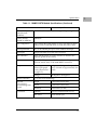
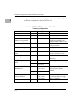
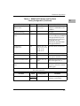
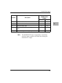
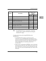
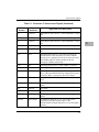
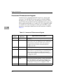
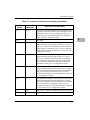
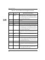
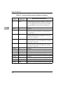
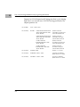
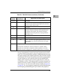
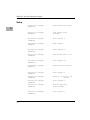
Table 5-1. Connector P1 Interconnect Signals (Continued)
Pin
Number
5
Signal
Mnemonic
Signal Name and Description
B28
IRQ3*
INTERRUPT REQUEST (3) - one of the seven
prioritized interrupt request inputs/outputs of the
MVME133XTS. Jumper enabled as input, and jumper
enabled as output.
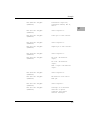
B29-B30
IRQ2*-IRQ1*
INTERRUPT REQUEST (2-1) - two of the seven
prioritized interrupt request inputs to the
MVME133XTS. Jumper enabled, level 7 is the highest
priority.
B31
+5V STDBY
Not used.
B32
+5 VDC
+5 Vdc power - same as +5 VDC on pin A32.
C1-C8
D08-D15
DATA bus (bits 8-15) - same as D00-D07 on pins
A1-A8.
C9
GND
GROUND - connected to the MVME133XTS ground
plane.
C10
SYSFAIL*
SYSTEM FAIL - signal driven by the MVME133XTS
when [BRDFAIL] is true if it is not the system
controller. Also can be monitored via the MC68901
MFP.
C11
BERR*
BUS ERROR - signal driven by the MVME133XTS bus
time-out circuit when it is the system controller and a
VMEbus data strobe cycle exceeds 72 to 82 µs. Also
monitored by the MVME133XTS when it is the
VMEbus master. It causes a bus error exception in the
MC68020 in this case.
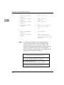
C12
SYSRESET*
SYSTEM RESET - signal driven by the MVME133XTS
when it is conÞgured as system controller during
power-up, when the front panel RESET switch is
depressed, when a watchdog time-out occurs, or when
remote reset becomes true. Also an input to the
MVME133XTS that causes all of its devices to be reset.
5-6