1
MPC860 Table of Contents
Welcome!
Getting Started
CHAPTER 1:
MPC860 Architecture, Part 1
CHAPTER 2:
EPPC Programming
CHAPTER 3:
Accessing Operands in Memory
CHAPTER 4:
Using the Caches
CHAPTER 5:
Memory Management Unit
CHAPTER 6:
EPPC Exception Processing
CHAPTER 7:
MPC860 Architecture, Part 2
CHAPTER 8:
Serial Communications Controller (SCC), Parameter
RAM, Buffer Descriptors, and a UART Example
CHAPTER 9:
More on the UART Protocol
CHAPTER 10:
HDLC Protocol
CHAPTER 11:
Ethernet Protocol
CHAPTER 12:
Serial Interface with Time Slot Assigner
CHAPTER 13:
QMC Mode on the 860MH
CHAPTER 14:
MPC860 Serial Management Channel (SMC)
CHAPTER 15:
MPC860 Serial Peripheral Interface (SPI)
CHAPTER 16:
I2C
CHAPTER 17:
Port Configuration
CHAPTER 18:
CPM Virtual IDMA
CHAPTER 19:
CPM Interrupt Controller
CHAPTER 20:
SIU Interrupt Controller
CHAPTER 21:
Memory Controller
CHAPTER 22:
MPC860 Reset Controller
CHAPTER 23:
General Purpose Timer and Other Timers
CHAPTER 24:
Clocks and Low Power
CHAPTER 25:
Bus Control Pins
CHAPTER 26:
Development Support
Welcome
Slide W-1
Welcome!
Motorola would like to welcome you to the MPC860 Training CDROM!
It is our hope that this will be a valuable tool in educating yourself on the operation of the MPC860.
Certainly you can use it to train yourself before you begin your design, but it should also prove to be a
handy reference once your design is underway. This training set should introduce a wealth of
information to the new designer as well as serve as a collection of insights to reinforce the knowledge of
the experienced engineer.
1
Slide W-2
Go through the training sequentially
as if you were taking the class
Use it as a random access reference
Be sure to take advantage of
all the useful functions
Before starting your design
review “Getting Started”
There are many ways in which you might want to use this training. The information has been arranged
in a sequential fashion, so if you desire, you may proceed through the course from start to finish as
though you were actually taking the class. It is also possible to use the Table of Contents or the
Keyword Index to randomly access the material as if you were thumbing through a manual.
As you use this application, be sure to make use of the additional functions such as playback control.
Have you ever sat through a class in which the instructor’s last comment simply didn’t sink in? Now, you
can use the playback control bar to restart the audio for a given slide as many times as you wish. You
may even want to back up the presentation by several slides so you can make sure you fully understand
the subject. Is the lecture moving too slow for you? Jump ahead to the next slide if you’re sure the
current one holds no new knowledge for you. Is it taking a little while for you to comprehend the current
diagram? Hit the Pause’
‘
button and review the slide until you are comfortable with it. Then you can
proceed with the narration.
We also provide reference materials per chapter. If the current slide is discussing something that you
want more detail about, then bringing up a reference file allows you to look over the relevant sections of
the user manuals and application notes
Another useful function is the ability to print the slide you are currently on. PDF files of the script and
slides are also included in this set for you, but perhaps you want a hard copy of what you are looking at
right now, so you can take it into the lab as a reference. Then one option is to print the bitmapped slide
from within the program.
There is more functionality available to you than just the examples we are using here. Please be sure to
review the instructions in the program as well as anyreadme file included with this training to become
familiar with all the functionality available to you.
Before the device training begins, we’ve included a collection of thoughts that may help guide your
design. The Getting
‘
Started with the MPC860’chapter contains information on how to acquire all the
2
different resources that are available to engineers of MPC860 applications, and includes step-by-step
tips on factors to consider before you begin your design.
Slide W-3
It is our sincere hope that you will find this training program as beneficial in some ways as attending a
class; perhaps given its random access reference nature, even more so.
We wish you best of luck with your design, and thank you for choosing Motorola.
And now, on to the training!
3
GETTING STARTED WITH THE 860
Slide GS-1
Getting Started with the MPC860
Once again, welcome to designing with Motorola’s MPC860 PowerQUICC!
We would like to thank you for choosing a Motorola processor. Motorola understands that in the field of
integrated communications controllers, you have a choice. We’re proud to have your business.
Before we proceed with the training course, we’d like to introduce you to some resources available to
you as an 860 designer. Then we’ll offer a step-by-step guide to developing hardware and software for
the 860, and point out materials that may support your efforts.
4
Slide GS-2
The Web
• http://www.mot.com/netcomm
• The best way to keep up with the resources
availble to you!
The Web
The World Wide Web has fast become the most efficient way to provide a wide variety of support
materials to customers. We invite you to visit our home on the web at:
http://www.mot.com/netcomm
The main NetComm home page tends to highlight new additions to the page and also contains the links
to the other sections of the site. As a designer, it is more likely that you will find three other areas of our
page most valuable: The Engineer’s Toolbox, the Publications Library, and the Support & FAQ area.
THE ENGINEER’S TOOLBOX
Click on the TOOLBOX for example code, schematics, monitor packages, part models, initialization
tools, and more. Files tend to be provided in a ZIP-compressed format or PDF format for Adobe’s
Acrobat Reader.
PUBLICATIONS LIBRARY
Click on PUBLICATIONS LIBRARY for our collection of users manuals, technical summaries,
application notes (or “appnotes”), and user manual errata (listed as manual addendums). Also in this
section you will find user’s manuals for our software, downloadable microcode packages, and our
development systems.
SUPPORT & FAQ
Click on SUPPORT & FAQ to find the latest device errata, as well as find information on how to
subscribe to our Mailing Lists which periodically broadcasts device news.
5
The Frequently Asked Questions (FAQ) page provides a search engine that gives you the power to
parse through actual helpline database issues on our products, accumulated over our years of
experience. Why lose valuable time-to-market investigating a bug in your design if someone has
already asked us about the same issue? When in doubt, check it out using the FAQ. Bookmark the link
http://www.mot.com/netcommfaq to go directly to the FAQ search engine.
Slide GS-3
Available Literature
MPC860 User’s Manual
• The most comprehensive guide to the device
• Document MPC860UM/AD
PowerPC Microprocessor Family:
The Programming Environments for 32-Bit Microprocessors
l Document MPCFPE32B/AD
The NetComm General Information CDROM
l
Item CDRONETCOM/D
Available Literature
THE MPC860 PowerQUICC USER’S MANUAL
The MPC860 User’s Manual provides the most detailed information about the part and its operation.
From I/O capabilities to programming models to interfaces, this is a must-have for anyone working with
the 860.
The manual’s document number is MPC860UM/AD and the manual can be obtained in electronic
format from the Publications Area of the web page or through the Literature Distribution Center
(discussed shortly).
We are pleased to announce that at the time of this training CDROM’s release, we are making available
the new REV 1 edition of the 860 User’s Manual. This new edition has updated tables and diagrams,
improved organization of the material, and new sections that better illustrate operation of the part to the
reader.
PowerPC 32-Bit MICROPROCESSOR MANUAL
This manual complements the MPC860 PowerQUICC User’s Manual by going into great detail on such
topics as the PowerPC register set, exceptions, and the PowerPC instruction set. The document
number is MPCFPE32B/AD.
6
THE NETCOMM GENERAL INFORMATION CD-ROM
Tired of downloading large documents from our web-site? We offer user’s manuals and large software
packages such as the MCUinit processor initialization tool in a CD-ROM format. While everything that is
contained on this CD-ROM is also located on the web, this disc may be more convenient for those
customers with low-bandwidth access to the internet. This disc may be obtained by contacting
Motorola’s Literature Distribution Center using the methods described in a moment, and requesting item
CDRONETCOM/D. Use the web for downloading smaller documents, and documents which could
change frequently.
Slide GS-4
The Literature Distribution Center
(LDC)
http://www.mot-sps.com/sps/General/sales.html
(subject to change)
USA/Europe/Locations Not Listed
P.O. Box 5405, Denver, Colorado 80217
1-800-441-2447 or 1-303-675-2140
Japan
Nippon Motorola Ltd.: SPD Strategic Planning Office
4-32-1, Nishi-Gotanda, Shinagawa-ku, Tokyo 141, Japan
81-3-5487-8488
Asia/Pacific
Motorola Semiconductors H.K. Ltd.
8B Tai Ping Industrial park
51 Ting Kok Road, Tai Po, N. T., Hong Kong
852-26629298
The Literature Distribution Center
Hard copies of our manuals and CD-ROMs can be obtained by contacting Motorola Semiconductor
Product Sector’s Literature Distribution Center (LDC). The LDC’s web page can currently be accessed
through the Literature Retrieval area of:
http://www.mot-sps.com/sps/General/sales.html
Additional contact information is shown here.
7
Slide GS-5
STEP-BY STEP GUIDE TO DESIGNING WITH THE MPC860
Is the MPC860 right for your application?
1. Look at the MPC860 variations
l
Use the “Products” area of our webpage
2. Obtain the User Manuals
l
l
Derivatives of the MPC860 still need the main
MPC860UM as well as the appropriate supplement
Derivatives of the MPC850 should use the main MPC850
manual as well as the appropropriate supplement
3. Read the introduction section of the UMs
l
Contains overview of featuresets
Step-by-Step Guide to Designing with the MPC860
IS THE 860 RIGHT FOR YOUR APPLICATION? (1 of 5)
With the complexity of chips these days, it can take a lot of time to make sure that a given chip is right
for your board. Here are some steps you can take to make sure the MPC860 is right for you.
1. Look at the MPC860 variations.
Go to http://www.mot.com/netcomm and click on the PRODUCTS icon. On the PRODUCTS page you
will see a list of MPC860 variations. Click on one of the variations and you will see a table that
illustrates the differences between the versions.
2. Obtain the right user’s manuals.
All the MPC860 family members require the MPC860UM/AD which is available from the web, from our
CD ROM, and from the Literature Distribution Center. If you want information on the MPC860MH,
MPC860DH you will also need the QMC User’s Manual supplement. If you need the MPC860SAR, you
will want its supplement. If you want the MPC860T, you will want its supplement that shows the
differences between the base MPC860 and that particular device.
If you are looking at one of the MPC850 family members, you would start with the base MPC850
manual instead of the MPC860 manual.
3. Read the introduction section of the user’s manuals.
This will give you an overview of the features of the chips. If you are looking at the MPC860DC (dual
channel device) or MPC860DE (dual Ethernet) devices, then the MPC860 base manual still applies, but
only SCC1 and SCC2 are available. SCC3 and SCC4 pins can still be used as parallel I/O ports, but
the SCC3 and SCC4 are non-functional.
8
Slide GS-6
STEP-BY STEP GUIDE TO DESIGNING WITH THE MPC860
Is the MPC860 right for your application?
4. Choose the right part for your communication functions
l
l
l
l
l
Let’s say we want Ethernet, HDLC and UART
This rules out the plain MPC860 as it does not have Ethernet
If the HDLC is multi-channel we need MPC860MH, the
MPC860DH, or the MPC850DH because these have the
QUICC Multichannel Protocol functionality
The MPC860MH does more than we need, and the
MPC850DH may not have the performance
Let’s use the MPC860DH for our example
(SCC1=Ethernet,SCC2=QMC, SMC1 or SMC2=UART)
STEP BY STEP: IS THE 860 RIGHT FOR YOUR APPLICATION? (2 of 5)
4. Choose the Right Part for your Communications Functions
The next area to investigate is whether the communications functions on the MPC860 are right for your
application. Decide what serial functions you want to accomplish at the same time. For example you
may want Ethernet, HDLC and UART.
You could assign Ethernet to SCC1, HDLC to SCC2, and UART to SCC3.
Since Ethernet is one of the choices, this rules out the “MPC860”, leaving the MPC860DC, MPC860DE,
MPC860DH, MPC860EN and MPC860MH.
If the HDLC support is multi-channel such as 24/32 time slots on fractional T1/E1 or several ISDN
BRI’s, this narrows the choice to the MPC860DH or MPC860MH. This protocol is called Quicc Multichannel Controller (QMC) in our documentation.
Now the choices become:
MPC860MH using Ethernet on SCC1, Multi-channel HDLC (also called QMC) on SCC2, and UART on
SCC3.
But wait, the MPC860DH only has 2 SCCs! Can it be used? Yes, because it has 2 SMCs also, which
are capable of low speed UARTs! So the MPC860DH is also possible with Ethernet on SCC1, Multichannel HDLC on SCC2, and UART on either SMC1 or SMC2.
Finally, it should be noted that the functions on SCC1 and SCC2 can be switched if needed on parts
that offer Ethernet on more than one channel such as the MPC860MH and MPC860DH.
9
What about the MPC850? Can it be used. The MPC850DH offers less CPU performance and less
capable communications functions, but the necessary functions can still be mapped similar to the
MPC860DH.
From reading section 1 of the MPC850DH manual, you will see that even though this part has 2 SCCs,
they are actually “SCC2 and SCC3” since SCC1 is replaced with a dedicated USB controller. In
addition the MPC850DH only has one SMC that can be connected to its own set of pins, so only SMC1
is possible.
Conclusion: So far, our most realistic options for this application are the MPC860DH and the
MPC850DH. Can both be used? It probably depends on the CPU performance required, which is
discussed later. For now, let’s stick with the MPC860DH for our example.
Slide GS-7
STEP-BY STEP GUIDE TO DESIGNING WITH THE MPC860
Is the MPC860 right for your application?
5. Check the Pinout of the Desired Part
Ethernet requires:
QMC requires (where “x” is A or B):
TXD1
TENA (on RTS1)
TCLK (on an unused pin from CLK1-CLK4)
RXD1
RENA (on CD1)
RCLK (on an unused pin from CLK1-CLK4)
CLSN (on CTS1)
L1TXDx
L1RXDx
L1TCLKx
L1RCLKx
L1TSYNCx
L1RSYNCx
SMC1 requires: SMTXD1, SMRXD1
SMC2 requires: SMTXD2, SMRXD2
l
l
l
l
We’ll use TDM A.
TDM A requires CLK1 and CLK3 pins
Therefore, Ethernet will use CLK2 and CLK4 pins
We’ll arbitrarily pick SMC1
STEP BY STEP: IS THE 860 RIGHT FOR YOUR APPLICATION? (3 of 5)
5. Check the Pinout of the Desired Part
In our example, we need to make sure that the MPC860DH will allow all the pins operating
simultaneously to support our configuration.
A reading of the Ethernet section of the manual shows us that the following pins are required if Ethernet
is used on SCC1:
TXD1
TENA which is mapped onto RTS1
TCLK which must be mapped to CLK1, CLK2, CLK3 or CLK4
RXD1
RENA which is mapped onto CD1
RCLK which must be mapped to CLK1, CLK2, CLK3 or CLK4, but must be a different pin than the one
used for TCLK above
10
CLSN which is mapped onto CTS1
Now go to the Signals Description of the Manual and look for those signals and circle them.
Now for the Multi-Channel HDLC support. This requires a time-slot assigner A or time-slot assigner B.
Which one should we use? You can use either -- whichever makes the rest of the pin assignment
easier. For this example, lets assume that the receive and transmit sides are completely independent
and therefore require their own separate clocks and synchronization pins. Then the pins we need are
as follows:
Choice 1 is TDM A and requires
L1TXDA
L1RXDA
L1TCLKA
L1RCLKA
L1TSYNCA
L1RSYNCA
Choice 2 is TDM B and requires
L1TXDB
L1RXDB
L1TCLKB
L1RCLKB
L1TSYNCB
L1RSYNCB
Note that these pins are easily distinguished from other SCC functions because they all start with L1
(Layer 1). If only one clock and one sync was needed then only L1RCLKx and L1RSYNCx would be
used.
Now go to the Signals Description of the manual and look for these signals and circle them. For our
example, we will choose TDM A rather than TDM B.
What you will notice is that L1RCLKA is an alternate function of CLK1 and L1TCLKA is an alternate
function on CLK3. Thus, we should go back to our Ethernet selections above, and choose CLK2 and
CLK4 so there is no conflict.
Another interesting thing to note is that L1TSYNCA and L1RSYNCA are available in 2 places on the
device! You can pick either location, and select it later in your software initialization. Why did we do
this? In a few case studies we did, we found that certain key applications required this kind of flexibility,
otherwise we would not have added this extra complication to the device!
Lastly, we need to select an SMC to use for the UART. Either SMC1 or SMC2. Thus our choices are:
SMTXD1and SMRXD1, or SMTXD2 and SMRXD2.
Note that the use of the SMCs means that we do not have RTS, CTS and CD functions. (If you must
have those functions, and software interrupts are not sufficient, then an SCC must be used, putting the
application back to an MPC860MH rather than the MPC860DH.)
An examination of the pinout reveals that indeed, everything fits on the MPC860DH, and it really didn’t
matter which SMC we chose, and which TDM we chose in this case. As you start to use more
channels, and more of the “optional” signals on certain interfaces, the chances of a contention
increases.
11
Slide GS-8
STEP-BY STEP GUIDE TO DESIGNING WITH THE MPC860
Is the MPC860 right for your application?
6. Check the Dual-port RAM of the Desired Part
l
l
Certain complex protocols use up the DPRAM of other functions
Check the web for microcodes that may patch situation
7. Check CPM Performance
l
l
l
Use the CPM Performance spreadsheet on the web!
Or use the Performance Appendix in the UM.
Example Calculations:
10/22 (Ethernet) + 2/8 (HDLC) = ~.70
(32 * 0.064)/2.1 (QMC) + 2/8 (HDLC) =1.22
1.22 * 25/33 = 0.92
This will work!
This is greater than 1.0 so it definitely will not work!
So at a greater operating speed, you can just squeeze it in
STEP BY STEP: IS THE 860 RIGHT FOR YOUR APPLICATION? (4 of 5)
6. Check the Dual-port RAM of the Desired Part
So now we know that the MPC860DH supports the simultaneous use of all the pins we need.
What is the next resource that could be a problem? The answer is the Dual-port RAM. Each protocol
requires certain parameters that are stored in the dual-port RAM. In the case of certain complicated
protocols like Ethernet and Multi-HDLC the parameter RAM requirement is so large that it actually
overruns the parameter RAM of other protocols. In our example Ethernet on SCC1 overruns the I2C
area, and QMC on SCC2 overruns the SPI area.
To solve this we have several downloadable microcodes that “patch” this problem by moving I2C and
SPI parameter RAM to other locations. This is called the “Microcode Patch for Relocating 12C/SPI
Parameters” and is available from the ENGINEERS TOOLBOX on our web-site.
7. Check the CPM Performance
Now that the pins and dual-port RAM requirements are checked to be OK for our application, we need
to check that the Communications Processor Module (CPM) performance is sufficient for the
application.
The method used to determine this is illustrated in the User’s Manual Appendix A, and involves a simple
equation based upon the system clock speed of the 860, as well as the protocols required and their
speeds. This Appendix lists the maximum expected performance of the 860 at 25 MHz for each kind of
functionality the 860 provides. This chart scales linearly, so as an example, if you intend to run the 860
at 50MHz, then these maximum bandwidth numbers also double.
We also offer an Excel spreadsheet called “CPM Performance Spreadsheet” that performs these CPM
loading calculations for you and it is located in the Engineer’s Toolbox of our web page. This is a very
useful tool!
12
To perform these calculations by hand, simply divide the intended bandwidth of a certain protocol by the
maximum, repeat for any additional functions you will be using, add all these fractions together, and do
not exceed a sum of 1.
This topic is covered in more detail in the training, but let’s do a quick example to illustrate what we are
describing. If the 860 were operating at 25MHz, and would be using a 10Mbit Ethernet channel in half
duplex and a 2Mbit HDLC channel, you would take these bandwidths, divide them by the max for each
protocol, and sum them as follows:
10/22 + 2/8 += 0.70
which comes close to, but does not exceed 1. So the processor would not be overloaded.
If you were to attempt 32 QMC channels at 64 Kbit each and one additional 2Mbit channel with the 860
at 25MHz, the following equation applies:
(32 * 0.064)/2.1 + 2/8 =1.22
This arrangement will not work. You can, however, keep this arrangement if you increase the operating
speed of the 860 to 33MHz, for example.
1.22 * 25/33 = 0.92
Now the CPM is not overloaded.
Slide GS-9
STEP-BY STEP GUIDE TO DESIGNING WITH THE MPC860
Is the MPC860 right for your application?
8. Check the PowerPC™ CPU Performance
At 66 Mhz, the 860 performed 87 Dhrystone MIPS
At 50 MHz, the 860 performed 66 Dhrystone MIPS
At 40 MHz, the 860 performed 52.8 Dhrystone MIPS
At 33 MHz, the 860 performed 43.56 Dhrystone MIPS
At 25 MHz, the 860 performed 33 Dhrystone MIPS
These numbers were obtained with a Diab Compiler.
9. Price and Availability
l
Check with your local distributor or Motorola representative
13
STEP BY STEP: IS THE 860 RIGHT FOR YOUR APPLICATION? (5 of 5)
8. Check the PowerPC CPU Performance
The last main area of concern is the CPU Core Performance. Our CPU offers the following Dhrystone
MIPS performance shown here.
These numbers were obtained with a Diab Compiler.
The good news about the Dhrystone benchmark is that the results for it, are available from a wide
variety of processors. The bad news about the Dhrystone benchmark is that it fits completely in internal
cache of 2K instructions or greater. Thus, the Dhrystone benchmark shows the 4K/4K (instruction
cache/data cache size) MPC860 family to be the same speed as the 2K/1K MPC850 family.
In actuality the performance of the MPC860 is 10-35% greater than the MPC850 family at the same
clock speed.
Another metric commonly used for the MPC860 is that this processor is about 10% faster than the
68040 processor at the same clock speed (which also has 4K/4K cache).
Finally, our TOOLBOX offers a benchmark “shell” which allows you to benchmark your own code on our
processor. This shell of code initializes the chip, turns on the MMU and Caches, and starts a timer for
you. It also shows you where to place your own “test code” to see how long it takes to run. The
example code that is included in this shell is the Dhrystone code.
9. Price and Availability
This information is not available on our web site, so check with your local distributor or Motorola
representative. Motorola’s main distributors are Arrow, Future, Hamilton-Hallmark and Wyle. Our web
site does contain press releases which show the “direct from Motorola” pricing at the time of the device
announcement, however pricing does change drastically with volume and with time.
14
Slide GS-10
STEP-BY STEP GUIDE TO DESIGNING WITH THE MPC860
Hardware Designers
1. Determine the Memory System You Will Need
l
l
l
Appnote:
Appnote: MPC860 Interface to Fast Page Mode DRAM
Appnote:
Appnote: MPC860 Interface to EDO DRAM
Appnote:
Appnote: MPC860 Interface to Synchronous DRAM
STEP-BY-STEP GUIDE FOR HARDWARE DESIGNERS
Now that you have decided to actually use the MPC860 in a design, the following steps are
recommended.
1. Determine the memory system you will need.
The MPC860 is a bursting device and thus obtains the best performance when the memory it is
connected to is also able to burst. The MPC860 burst is comprised of four 32-bit words. If the length of
the burst is written as 4-2-2-2, then the first 32-bits were read/written in 4 clocks, the next 32-bits in 2
clocks, and so on for a total burst length of 10 clocks. The following table shows some example burst
lengths for a BURST READ operation. (BURST WRITES are usually slightly better).
Note that faster memory can yield better results. Also note that for the 66 Mhz devices (or any device
used in half speed bus mode) the actual bus speed may only be one half of the processor speed. Thus
a 66 Mhz device might only have a 33 Mhz external bus. Whether a 66/33 (internal/external) device is
faster than a 50/50 device will depend on the cache hit rate and the external memory speed.
More information on the various memory types can be obtained in the following collection of appnotes:
MPC860 Interface to Fast Page Mode DRAM
MPC860 Interface to EDO DRAM
MPC860 Interface to Synchronous DRAM (SDRAM)
15
Slide GS-11
STEP-BY STEP GUIDE TO DESIGNING WITH THE MPC860
Hardware Designers
2. Obtain Example Schematics
--Check the Web: MPC860FADS Schematics, MPC860 Part Symbol, BGA Footprint
3. Obtain User’s Manual Errata and Device Errata
4. Remember the 5V Tolerance
5. Look at Clocking Issues
--Appnote: Crystal Note for the 302, 360, and 8xx Family
6. Look at Pin Termination
--Pin Termination for the MPC860 white paper
7. Look at Pin Timing Issues
--Electronic Data Book of MPC860 timings
8. Check the Hardware Configuration Register Carefully
9. Read the MPC860 Design Checklist
10. Get the Part Up and Running
11. Having Trouble? Search the FAQ
12. Get on the MPC860 Update List Email Server
STEP-BY-STEP GUIDE FOR HARDWARE DESIGNERS (2 of 2)
2. Obtain Example Schematics
The web site offers several sources of example schematics available in ORCAD format. The most
useful set is probably the SAMBA schematics, which shows how to interface the entire MPC860 family
to memory -- Flash EPROM, DRAM, and SDRAM. In addition, it shows the MPC860T connected to an
external 10/100baseT Transceiver.
In addition, the schematics for our MPC860FADS boards are also available, however, this board is
designed to be very flexible, and may not represent the most efficient system design.
860 PART SYMBOL: An 860 electronic part symbol in ORCAD Capture format is also on the web.
BGA FOOTPRINT: The documents AN1231 and AN1232 are in-depth discussions about factors
regarding the BGA package that the 860 uses and includes a footprint for design purposes.
3. Obtain User’s Manual Errata and Device Errata
This information is available on our web site in the PUBLICATIONS and SUPPORT & FAQ sections
respectively.
4. Remember the 5V Tolerance
Although the MPC860 family is a 3.3V supply device, it is 5V tolerant and can be used with 5V TTL
compatible components.
5. Look at Clocking Issues
16
Although the part allows both crystals and oscillators to be used, we recommend oscillators to be used if
possible. Oscillators reduce the risk of process variations or process shrinks from causing the clocking
circuit to cease operation.
For those that must use crystals, we recommend that engineers inquire to their crystal manufacturer to
determine the best capacitor and crystal characteristics. They are in the best position to estimate the
values needed for the circuit.
We do provide the appnote “Crystal Note for the 302, 360 and 8XX Family.” This paper is written to
assist engineers in the production of reliable clock circuits which may be used with devices such as the
MPC860, MC68360 and MC68302 and their derivatives. It discusses in general terms various methods
for the generation of the system clock.
6. Look at Pin Termination
A frequent issue of concern is the proper termination of signal pins. This is the most common reason
why a MPC860 board does not work at power-up. Which pins should be pulled up or down for proper
operation of the 860? We have produced a white paper on this very subject and it can be found in the
Publications Area of the web.
7. Look at Pin Timing Issues
When designing your circuits involving the 860 you will obviously take care to meet the timing
specifications of the 860. In addition to the timing diagrams in the 860 manual, we also provide some
additional tools to help understand your timing needs.
On the web, in the Publications Area, is the MPC860 Electrical Specifications Spreadsheet. This Excel
document dynamically calculates timing specifications based upon operation speed and capacitive
loading. You can program the exact frequency of your system bus, and this tool will customize the
MPC860 timings for you. In addition, you can program the capacitive loading on the pins, and the tool
will customize the timings.
We also have available an electronic data book of the 860 timings that can be used with Chronology’s
TimingDesigner tool. This software aids in visualizing signal waveforms and timings.
8. Check the Hardware Configuration Register Carefully
The MPC860 has a number of different modes that can be programmed in hardware. You select the
modes by driving certain voltage levels onto the Data Bus pins during reset. Any Data Bus pins that you
do not drive will take on the default configuration. Out of the 15 or so pins, you will probably only need
to drive 4 or 5 -- the rest can use the defaults. Please read this section of the manual very carefully as
you are making very basic decisions about the operation of the part.
9. Read the Design Checklist
When you think you have everything under control, go back and read the MPC860 Design Checklist
which resides in the PUBLICATIONS section of our web site. This gives a number of helpful hints and
lists some common mistakes.
10. Get the part up and running.
When you get the boards back, the first thing you should do is bring the part up in its debug mode. In
the debug mode, you can control the part through the debug port without requiring the device to execute
any software on the board itself. The debug port pins of the MPC860 should be brought to a simple
header that is described in the APPLICATIONS section of the MPC860 User’s Manual. This will allow
many standard debuggers to access the device. In fact, if you purchased an MPC860 FADS board,
you can use our MPC8bug on the host PC to control to your target board through the MPC860 FADS
board. See the MPC860FADS manual for more information on this option.
17
11. Having Trouble?
Don’t forget to check the searchable FAQ at:
http://www.mot.com/netcommfaq
for hints on what might be wrong.
12. Get on the MPC860-Update List Server
See the SUPPORT & FAQ section of our web site to subscribe to get real-time updates of late breaking
news on the MPC860.
SLIDE GS-12
STEP-BY STEP GUIDE TO DESIGNING WITH THE MPC860
Mechanical and Component Engineers
1. Read the Packaging Appnote
l
http://www.mot.com/pbga
2. Look at Thermal Considerations
l
Appnote:
Appnote: Thermal Considerations and Measurements
3. Look at Power Dissipation
l
The MPC860 varies from 0.4W to 0.8W depending on frequency
4. Qualification Data
STEP-BY-STEP GUIDE FOR MECHANICAL AND COMPONENT ENGINEERS
Here are some additional steps to consider.
1. Read the Packaging Appnote
The MPC860 family resides in a 357 lead Plastic Ball Grid Array (PBGA) package. An appnote for the
use of this package and PBGAs in general may be found at:
http://www.mot.com/pbga
2. Look at Thermal Considerations
NetComm has available in the Publications Area a new appnote covering thermal considerations and
measurements for the 860 and its packages.
18
If extended temperature (-40 to +85) is required, may not be offered in at all speed grades, and may
require heat sinks at the highest speed grades.
3. Look at Power Dissipation
The MPC860 family tends to vary from 0.4W to 0.8W depending on frequency. The power dissipation
at a given frequency is decreasing as the device undergoes shrinks. Meanwhile the offered frequency
is increasing over time. The end result is that the power dissipation for the highest speed versions tend
to be in the 0.8W range.
The first MPC860 User’s Manual showed an option of running the internal circuitry of the MPC860
family at 2.2V (rather than 3.3V) to save power. This option has NOT been productized in the MPC860
or MPC850 family, and is not available.
4. Qualification Data
Qualification reports are available for our devices, however they can only be obtained through a
Motorola Sales office.
SLIDE GS-13
STEP-BY STEP GUIDE TO DESIGNING WITH THE MPC860
Software Designers
1. Determine Your Tool Set
--Visit the MPC860 Third Party Support Page
2. Review the Motorola Application Development System Materials
--MPC8bug: Motorola’s command line monitor/debugger
3. Acquire MCUinit
--MCUinit: Motorola’s GUI-based initialization code generating package
4. Study Exception Processing and Interrupts
5. Obtain Basic Chip Initialization Code
6. Obtain Device Drivers and Example Code
7. Read the CPU Performance Appnote
--Appnote: MPC8xx Performance Driven Optimization of Caches and MMUs
8. Scan the Performance Checklist
9. Having Trouble? Search the FAQ
--http://www.mot.com/netcommfaq
10. Get on the MPC860 Update List Email Server
STEP-BY-STEP GUIDE FOR SOFTWARE DESIGNERS
1. Determine Your Tool Set
An incredible amount of support is also available in many forms from companies outside of Motorola. A
list of those companies organized by category of support, their contact information and links to their web
sites (if available) are located on our web site. At the top of various pages throughout our web site you
will see links to the 860 Third Party Support Page.
19
Categories of support include: Board Test Consultants, Chip Drivers (Software), Generators and Tools,
Companion or Support Chips, Development Systems, Emulators, Hardware Models, Network Software,
Operating Systems, and Package & Socket Adapters.
We highly encourage you to investigate these companies’ products and services in your efforts to get
your product to market.
2. Review the Motorola Application Development System Materials
Among the most important support materials available to our customers is the MPC8xx Family
Application Development System (8xxFADS). This package is meant to serve as a platform for
software and hardware development around the 860 family of devices. Using the on board resource
and the associated MPC8bug debugger/monitor, a developer is able to load their code, run it, set
breakpoints, display memory and registers and connect the developer’s own proprietary hardware via
the expansion connectors. The FADS is not just effective for testing purposes but can also serve as a
demonstration tool. Contact your local Motorola Sales office for details on how to purchase the
systems. Information on how to find the most appropriate sales channel can be found on the web.
MPC8BUG
Motorola provides its own command line debugger/monitor program called MPC8bug. This package
provides excellent simple methods of observing and debugging your code and performing diagnostics.
You can even write your own diagnostics with the new 1.3 release of the software. This software is
shipped with the 860ADS or 8xxFADS, and is also available on the web.
3. Download MCUinit
Interested in using a graphic interface tool to quickly produce initialization code for the 860? You need
to check out MCUinit, a menu-driven initialization code generating program for 32-bit Windows
compatible computers. This software package is located both on the web and on the NetComm
General CDROM.
4. Study Exception Processing and Interrupts
There is also the MPC860 EPPC Exception Processing Application Note with deals with exception
processing in more detail.
In addition, two appnotes are provided on interrupts -- one for the SIU and one for the CPM.
5. Obtain Basic Chip Initialization Code
Look in the ENGINEERS TOOLBOX on the web to obtain the latest MPC860 Initialization code. This
shows how to bring the device up from power-up including the programming of clocking modes and chip
selects.
6. Obtain Device Drivers and Example Code
The Engineers’ Toolbox is your best resource for freeware available from Motorola for use with the 860.
On the web you will find both simple tutorial-style examples, and some complex drivers as well, that
demonstrate a wide variety of protocols and modes of operation from setting up timers to running
Ethernet. The list of code available is being updated all the time, so check the web often. We currently
have drivers or example code for HDLC, Ethernet, UART, Transparent, Real-time clock, I2C, the
PowerPC Timebase, ATM SAR for the MPC860SAR.
Drivers are also available for a fee from third parties such as AISYS, Inverness, and Trillium and are
often included with a purchase of an RTOS for the MPC860.
7. Read the CPU Performance Appnote
20
The MPC860 core has two Memory Management Units and two caches, one of each for data and for
instructions. We invite you to study our Cache and MMU appnote package, available in the Publications
area of the NetComm web site, which explains how to efficiently use the caches and MMU. It includes
the appnote itself, a special version of the debugger/monitor NetComm offers with cache hit simulation
ability, and some scripts (given as examples in the appnote) that can be used with the debugger. The
appnote is named “MPC8XX Performance Driven Optimization of Caches and MMUs”.
8. Scan the Performance Checklist
In the Publications Library is the MPC860 CPU Performance checklist. This document is basically a
quick summary of the most important facets of the Performance Appnote mentioned above. Topics
that are covered include dealing with DRAM, interrupts and their handlers, core operation modes and
more. If you are not getting the performance you expect, this is the place to start.
The MPC860 has so many debug assist modes that it is not uncommon for customers to see a 2x to 3x
performance improvement, after following the guidelines in this checklist.
9. Having Trouble?
If you are having trouble getting your serial protocols to work try looking at the appnote “Hints for
Debugging the CPM”. This shows you how to determine where the problem resides, by showing you
how to trace the flow of data from system memory to the pins, and from the pins back to system
memory.
Also, don’t forget to check the searchable Frequently Asked Questions at:
http://www.mot.com/netcommfaq
10. Get on the MPC860-Update List Server
See the SUPPORT & FAQ section of our web site to subscribe to get real-time updates of late breaking
news on the MPC860.
21
Chapter 1: MPC860 Architecture, Part 1
SLIDE 1-1
MPC860 Architecture, Part 1
What you • Identify the basic blocks of the MPC860 and their functions
will learn • Describe the function of each component
• Describe how internal data flows
• Identify the pin groups
• Describe an example application
In this chapter you will learn to:
1. Identify the basic blocks of the MPC860 and their functions
2. Describe the function of each component
3. Describe how internal data flows
4. Identify pin groups
5. Describe an example application
22
SLIDE 1- 2
What are the Basic Components?
System Interface Unit
2
4K
I Cache
I MMU
Core
PowerPCTM
Parallel I/O
Baud Rate
Generators
Parallel Interface
Port
1
Memory Controller
U-bus
BIU
System Functions
Real Time clock
4K D
Cache
D MMU
PCMCIA Interface
Internal
4 General
Interrupt
Memory
Purpose
Controller
16 Serial
Space
Timers
DMAs;
32-Bit RISC µController
2 Virtual IDMA
and Program ROM MA
Internal
C Bus
Timers
Peripheral
3
I2C
SCC1 SCC2 SCC3 SCC4 SMC1 SMC2 SPI1
Serial Interface
Time Slot Assigner
Communications
Processor
Module
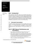
What are the basic components of the MPC860?
This is a block diagram of the MPC860. It consists of three major blocks: the PowerPC core, the
System Interface Unit (or SIU), and the Communications Processor Module (or CPM).
The PowerPC is the main processor unit, and is commonly referred to as the Embedded PowerPC
Core (or EPPC for short [pronounced “epic”]). It includes the caches and Memory Management Unit
(also known as the MMU). It has a performance capability of 52 mips with a 40 megahertz clock.
The second major block is the System Interface Unit. One of the primary functions of the SIU is to
provide an interface between the internal Unified bus and the external bus. It also provides a number of
other functions as shown here.
Finally, the third major block is the Communications Processor Module. The CPM sends and receives
data over eight different communication devices, such as the Serial Communication Channels (SCC) or
Serial Management Channels (SMC). All of the devices can be used individually, or the SCCs and
SMCs can be used on a Time Division Multiplexed Bus.
Notice that within the Communications Processor Module, there is a 32-bit RISC micro-controller. The
MPC860 contains two CPUs: the PowerPC and the 32-bit RISC. The PowerPC executes the code of
the higher layers to maximize throughput. The CPM RISC takes care of the low-level aspects of
communication such as moving characters to and from memory, and handling the actual
communication. Of course, the two processors must have some means of coordinating efforts. The
primary means is via the internal memory space. In this memory area, each processor can set control
bits, and read status bits to which the other processor can then respond.
Also in this diagram, there are 16 serial DMAs or Direct Memory Access units. Each of the eight
communication devices has a transmit DMA and a receive DMA. The 32-bit RISC directs these 16
serial DMAs to transfer data between the communications devices and memory, usually external
memory. When the MPC860 receives data, the serial DMA obtains the data from the communication
23
device and moves this data into memory. For data transmission, the sequence occurs in reverse, with
the data originating in memory, and the serial DMA transferring that data to the communication device.
The serial DMAs are used exclusively by the CPM RISC; however, there are two virtual IDMAs available
for user DMA requirements.
SLIDE 1- 3
How Data Flows
System
1
3
Interface
Unit
U-bus
PowerPCTM
2
4
Internal
Memory
Space
Peripheral Bus
16
Serial
DMAs ;
2 Virtual
IDMA
Communications
Processor
Module
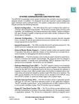
How does data flow?
This diagram shows the major paths for data flow within the 860. The first path as shown is from 1 to 3;
data flows from the PowerPC to the SIU. The core uses this path when executing load and store
instructions that miss in cache, or that are not cacheable. The cache controllers within the PowerPC
also use this path when loading and flushing cache. The MMU processes the addresses used on this
path.
The second path as shown is from 1 to 2; data flows from the PowerPC to the internal memory space;
this path occurs for accesses to registers and to dual-port RAM within the internal memory. The MMU
processes these addresses, but because both processors can write to this memory, this data area
should not be cached.
The third path as shown here is from 4 to 3; data flows from the peripherals to and from the external
bus. This is the path that is used for moving data between external memory and the communications
peripherals. The MMU does not process the addresses, and data should not be cached.
The final path as shown here is from 4 to 2; data flows from the peripherals to the internal memory
space. This path occurs for data transfers between peripherals and dual-port RAM. This path is not
used often, although you may wish to use it occasionally. Normally, the data buffers are placed in
external memory; however, it is possible to place buffers in the dual-port RAM area of the internal
memory space. The limitation is that the internal memory space is not very large. The MMU does not
process the addresses, and data should not be cached.
24
SLIDE 1- 4
What are the Pinouts?
Power Pins
VDDSYN, VSSSYN
VDDH,VDDL,VSS,
KAPWR
Address (0:31) Bus
Data (0:31) Bus
Port A
PA0-PA15
Port B
PB14-PB31
Bus Control
MPC860
Interrupts
Memory Control
Port C
PC4-PC15
Port D
PD3-PD15
Reset
Crystal/Oscillator
PCMCIA Port A
JTAG/Dev. Supp.
Pin Group
Diagram
PCMCIA Port B,
Dev. Supp.,
Program Tracking
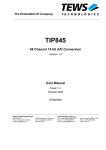
What are the pinouts?
Here is a summary diagram of the pin groups of the MPC860. A more detailed diagram is available in
the User Manual. Here is shown a 32-bit address bus, a 32-bit data bus, and the bus control pins. Most
users can support their memory and I/O interface requirements with the memory controller pins, since
these pins can provide a direct interface to almost any device. However, if all of the chip select pins are
in use, or if a rare device is in use that the memory controller cannot support, then the user can
implement the bus control pins as an interface to a device. The user will need to provide additional logic
for the interface if they implement the bus control pins.
There are eight interrupt pins, and, as mentioned, the memory controller pins. There are also pins
associated with hard and soft reset. Additionally, there are pins that allow the user to supply a clock. It
is possible to supply a clock with a crystal, an external oscillator, or both.
The MPC860 supports two PCMCIA ports. The pins for PCMCIA Port A are standalone; that is, the
pins for PCMCIA Port A are dedicated to that function. The pins for PCMCIA Port B, however, are
shared with the Development Support capability and the program tracking functions. You might call the
right side of the diagram shown here the system side, while you might call the left side of the diagram
the communications side. For the most part, the communications side consists of four ports: Port A, B,
C and D. Each of these pins can act as a general-purpose I/O or support at least one alternate function
associated with a communications device, such as receive or transmit. Part of the designer's task is to
determine how to use each one of these shared pins. There is also a set of pins associated with JTAG,
and Development Support shares these pins.
25
SLIDE 1 - 5
What is an Example Application?
Optional
CAM
Ethernet
TP
RJ-45
Glue
MPC860
EEST
MC68160
SCC1
AUI
RS-422
D -15
Localtalk
T1/E1 Line
8, 16, or 32-bit
Boot ROM
Power
PC
Core
DRAM SIMM
16 or 32 - bits
SCC2
32-bit
RISC
T1/E1
Transceiver
Memory
Cntrlr
TDM-A
SCC3
Time
SCC4
ISDN-Basic or Primary
Slot
SMC1
S/T/U
S/T/U TDM-B Assigner
Transcvr
IDMA 1
IDMA 2
RS-232
Local
SMC2
PCMCIA
Terminal
Serial EEPROM MCM2814
SPI
Qspan-860
Peripheral 1
Peripheral 2
Buffers
I2C
PCI
Bus
Port A
Port B
Peripheral
What is an example application?
This diagram shows a few ideas of how the user might implement some of the devices on the MPC860.
The SCCs are capable of supporting a number of protocols. . Here, for example, in the upper left-hand
corner, SCC1 is shown connected to an Ethernet transceiver on an Ethernet network. Any of the SCCs
support the Ethernet protocol, however. Here, for example, SCC2 supports an interface to a LocalTalk
network.
Furthermore, it is also possible to provide an interface to one or two Time Division Multiplexed buses:
TDM-A and TDM-B. Here connections are shown to a T1/E1 line, and an ISDN interface as examples.
In such a case, a timeslot assigner routes data on the buses to any of the SCCs, or to any of the SMCs
-- for a total of six devices to which data can be routed.
Serial management controllers do not have as much capability as SCCs, but a very common
implementation for one of the SMCs is to use it with a local terminal as shown here.
A Serial Peripheral Interface is available for communicating with a variety of peripheral devices,
including a number of transceivers, which can be programmed through the SPI bus. Here we show the
Serial Peripheral Interface with a double EEPROM.
There is also an InterIntegrated Circuit (I2C) controller providing an interface to a number of peripherals.
The I2C is a good device to consider if the user intends to use SIMMs for example, in which the
presence detect function is implemented using an EEPROM with an I2C interface.
Additionally, the PCMCIA controller supports two PCMCIA boards.
External buffers for PCMCIA and bus transceivers must provide electrical isolation between the sockets
and the system bus. The MPC860 is a 3.3-volt device, but with the exception of the clock input it is 5volt friendly; therefore no voltage conversion is required for inputs other than those for the clock.
26
We have mentioned previously that there are two IDMA devices; these devices are available to transfer
data from peripherals, as well transfers from memory to memory.
Finally there is the memory controller. It is possible to program the memory controller to boot up from 8, 16-, or 32-bit ROM; likewise, the memory controller can provide an interface to a DRAM SIMM, or a
wide variety of other memory devices. The memory controller can also connect to a PCI bus using
devices available from 3rd-party manufacturers.
SLIDE 1-6
What are the Basic PowerPC core Components (1 of 3)?
What are the Basic EPPC Components (1 of 3)?
I-cache/I-MMU interface
D-cache/D-MMU interface
L-addr
Core
Sequencer
L-data
1
Address
Branch
Instruction
generation
unit
queue
3
2
4
control bus
write back bus
(2 slots/clock)
Special
Regs
GPR
32x32
GPR
history
IMUL/
IDIV
ALU/
BFU
LDST
address
LDST
fix data
source busses
(4 slots/clock)
Let us now turn our attention to the PowerPC core of the MPC860. Here we have a block diagram, and
the focus is on the sequencer. The sequencer provides centralized control of instruction flow to the
execution units, shown in the lower portion of the block diagram. The Address Generation unit supplies
an address to fetch the next instruction based on information from the sequencer and from the Branch
Prediction Unit. The Branch Prediction Unit extracts branch instructions from the sequencer, and uses
static branch prediction on unresolved conditional branches to allow the instruction unit to fetch
instructions. The instruction queue holds the next instructions to be distributed.
The Branch Prediction Unit examines an instruction to determine if it is a branch instruction or not. The
Branch Prediction Unit then passes the instruction on to the instruction queue. The instruction queue
moves the instruction from the Branch Prediction Unit to the head of the queue, and then dispatches it
to the appropriate execution unit.
The Branch Prediction Unit does not take any action if an instruction is not a branch instruction. If an
instruction is a branch instruction, the Branch Prediction Unit makes a static prediction of whether the
branch will be taken or not. Based on the Branch Prediction Unit’s decision, the Address Generation
Block obtains the instruction either from the next sequential address, or the instruction at the location to
which the branch will go. Static branch prediction is performed according to how the user programmed
27
the branch instruction. For the few times that the prediction is wrong, the instruction queue will have to
be flushed out, and the instructions from the other location will have to be brought into the instruction
queue.
Here are three of the execution units. One of the execution units supports the general-purpose registers.
These are registers for temporary, pointer, and index data. There are thirty-two, 32-bit general-purpose
registers, and they all operate in essentially the same way. The special purpose registers are used for
control and status data, as well as save and restore data. There are actually more special purpose
registers than general-purpose registers.
There is also a history buffer (GPR History). As the core dispatches each instruction, the instruction
enters the history buffer. The core sets various status bits showing the progress of the instruction as it
executes. When the instruction completes, it exits the history buffer. While the instruction is in the
history buffer, and perhaps partially executed, an exception could occur, in which case the MPC860 has
the capability to back up the machine to the instruction that caused the exception, and then handle the
exception.
The Integer Multiply / Divide Unit executes integer multiply and divide instructions. There is an Arithmetic
Logic Unit with Bit Field Logic Unit combined, which executes all other integer and bit instructions. Next,
there are two units associated with load and store, one for address one for data. Both units consist of a
two-entry 32-bit queue. All load / store instructions share the Load / Store Address queue. The Load /
Store Fixed-Point Data Queue holds fixed-point data.
28
Chapter 2: EPPC Programming
SLIDE 2-1
EPPC Programming
What you
will learn
Learn how to:
• Write program loops
• Write subroutines
• Test and manipulate bits in I/O devices
• Implement signed and unsigned arithmetic algorithms
In this chapter, you will learn how to:
1. Write program loops
2. Write subroutines
3. Test and manipulate bits in I/O devices
4. Implement signed and unsigned arithmetic algorithms
29
SLIDE 2-2
Overview of Programming Model
User Programming Model (same for all EPPC implementations)
General Purpose
Registers
GPR0
GPR1
Special Purpose
Registers
GPR30
GPR31
Condition Register
XER
LR
CTR
TB
TBU
Program Counter
Supervisor Programming Model ( changes for different EPPC implementations)
MSR
Machine State Register
Standard SPRs
DSISR
DAR
DEC
SRR0
SRR1
Additional SPRs
SPR80-82:
SPR560-570:
SPRG1
bit manipulation Icache & Dcache
SPRG2
of MSR[RI&EE] control/status
SPR784-826:
SPR144-630:
SPRG3
MMU
Debug &
TB(to write) development
programming
model
support
TBU(to write)
SPRG0
PVR
Overview of the Programming Model
This slide illustrates a general view of the programming model for the MPC860. It is divided into two
parts: the user programming model, and the supervisor programming model. The user programming
model is essentially a subset of the supervisor model.
30
SLIDE 2-3
Overview of Programming Model
User Programming Model (same for all EPPC implementations)
0
31
GPR0
GPR1
SPR1
XER
SPR8
LR
SPR9
contain
data and
addresses SPR268
of the
task in
execution SPR269
CTR
TB
arithmetic OV,CA,SO
Subroutine return
address
Goto address/loop count
Free running TimeBase
count (read only)
TBU
GPR30
GPR31
0
31
8 fields for
condition
evaluation
Condition Register
Not directly accessible
0
31
Program Counter
User Programming Model
First, let us discuss the user programming model. Note that when we discuss the user model, this is
synonymous with the problem state of operation.
Within the user programming model, there are thirty-two general-purpose registers. Each register is 32
bits wide. All of these registers operate in essentially the same way. EPPC computations are register to
register. Information is saved to, and restored from, registers. On the PowerPC, there is no stacking
mechanism, and therefore no dedicated stack pointer. Although the hardware provides no stacking
mechanism, the user may implement stacking functions through software. While there is no dedicated
stack pointer register, by convention, General Purpose Register (GP(R1)) acts as the stack pointer
register.
Another register in the user programming model is the Condition Register (CR), consisting of eight, 4-bit
fields. We discuss this register in more detail later in this chapter.
Also in the user programming model, there are five special purpose registers. SPR1 is the Integer
Exception Register (XER) register, which is used for multi-precision arithmetic, and has an overflow,
carry, and summary overflow bit.
Next is the Link Register, Special Purpose Register 8 (SPR8). This stores the return address when a
call to subroutine instruction executes.
SPR9 is the counter register. This is commonly used as a counter register in loop programs.
Alternatively, the programmer can also use this register for a GOTO, in which the routine stores an
address, and branches to the location to which the address points.
The remaining two special purpose registers are for the TimeBase - SPR 268 and 269. This is a 64-bit
time value, to be used as a time stamp. It is part of the PowerPC architecture. The user has access to
this TimeBase through these registers on a read-only basis.
31
Finally, there is a program counter in the user programming model; however, it is not directly accessible
to the user.
SLIDE 2-4
Overview of Programming Model
Supervisor Programming Model ( changes for different EPPC implementations)
0
31
MSR
Standard SPRs
cause & address
of storage fault
@ exception time
Machine State
Register
free running
contains:
decrementer
•State info
•Exception enables return address
& state @
•MMU enables
SPR18
SPR19
SPR22
SPR26
time of exception SPR27
SPR272
for OS
scratch pad
SPR273
SPR274
SPR275
SPR284
SPR285
processor version & rev
SPR287
Additional SPRs
DSISR
SPR80
SPR81
DEC
•
•
SRR0
•
SRR1
•
SPRG0
•
•
SPRG1
•
SPRG2
•
SPRG3
•
•
TB(to write)
SPR825
TBU(to write)
SPR826
DAR
PVR
SPR80-82:
bit
manipulation
of
MSR[RI&EE]
SPR144-630:
Debug &
development
support
SPR560-570:
Icache &
Dcache
control/status
SPR784-826:
MMU
programming
model
Supervisor Programming Model
Now let us discuss the supervisor programming model. Note that when we discuss the supervisor
model, this is synonymous with the privileged state of operation.
In the supervisor programming model, there is the Machine State Register, which contains information
about the machine state, such as enabling exceptions, or interrupts.
There is also a set of standard special purpose registers. The first two standard SPRs -- the Data
access exception Source Instruction Service Register (DSISR) and Data Address Register (DAR) -store information when certain exceptions occur, especially error exceptions.
The next register is the Decrementer register. This register also functions as part of the PowerPC
architecture. The value in this register constantly decrements, and it is possible to set an interrupt to
occur when the value reaches zero.
The next two registers, Save and Restore Registers 0 and 1 (SRR0 and SRR1), are always used in
exception processing. The exception service routine saves the Machine State Register and the
program counter into these two registers.
The next four registers are available for the operating system to use, as it requires.
Special purpose registers 284 and 285 are available for the TimeBase. In this case, the supervisor can
access these registers and write a new value to the TimeBase.
Special purpose register 287 contains the processor version and revision number.
32
There are quite a few additional special purpose registers, including those that affect the Machine State
Register; others that control debug and development support, and others affecting cache and the MMU.
More detail on these registers is included in the chapters covering the associated subjects.
SLIDE 2-5
Data & Instructions (1 of 2)
Data sizes
• The most significant bit (bit 0) is on the left. Bit numbers increase
toward the least significant bit (LSB). The LSB is bit 7 for byte, bit 15 for
halfword, and bit 31 for word.
0
7
byte
0
15
halfword
0
31
word
Instruction size
The instruction size is word for all EPPC processors. Instructions are
word-aligned so that the two low order bits of an instruction address are
not needed, or are zero.
0
31
word
Data and Instructions (1 of 2)
Here are shown the data sizes for the PowerPC. There are three data sizes: byte, half-word, and word.
Also, we’d like to make a quick point about bit numbering in the PowerPC world. Bits are labeled left to
right, most significant to least significant, as 0 to 31. It is strictly a bit labeling convention only and does
not apply at all to significance. Bit 0 is still most significant, and unless in an alternate mode of
operation, PowerPC uses Big Endian byte ordering by default.
The PowerPC architecture does not support dynamic bus sizing; therefore, it does not allow misaligned access.
The instruction size on the PowerPC is always one word. Instructions are word-aligned so that the two
low-order bits of an instruction address are not needed, or are zero.
33
SLIDE 2-6
Data & Instructions (2 of 2)
The first instruction format does an operation with a GPR (rA) and 16-bit
immediate data (sign or zero extended to 32bits). The second does an operation
with two GPRs (rA & rB). Both place the results into a destination GPR (rD).
Operations are always 32 bits and write 32 bits to rD.
General Syntax
Encoding
0
Instr rD,rA,rB
5 6 10 11 15 16 20 21
Opcode rD
0
Examples
rA
rB
30 31
Subopcode 0
5 6 10 11 15 16
add r3,r4,r6
or r16,r12,r3
31
addi r3,r4,750
ori r14,r5,0x100
d = UIMM (16-bit unsigned immediate data), or SIMM (16-bit signed immediate data)
Instr_i rD,rA,0xXXXX
opr =operation (+,-,*, ÷,etc)
Opcode rD
rA
Instruction syntax
instr rD,rA,rB
add
rD,rA,rB
sub
rD,rA,rB
mul
rD,rA,rB
div
rD,rA,rB
subf rD,rA,rB
d
Algebraic Operation
rD = rA<opr>rB
rD = rA + rB
rD = rA - rB
rD = rA * rB
rD = rA ÷ rB
rD = rB - rA
Data and Instructions (2 of 2)
There are two primary formats for instructions. One includes the instruction mnemonic, followed by
three operands - rD, rA and rB. rD refers to the destination register, while rA and rB determine the
contents of the source register. Refer to the examples on the right side of the chart. In the case of an
"add r3, r4, and r6", the sum of r4 and r6 is placed in r3. In the case of a logical operation, such as an
"or", r3 is 'OR'd' with r12, and the result is placed in r16.
A similar format is the 'instruction immediate', in which an 'i' follows the instruction mnemonic. In this
case, the third operand is an immediate value of 16 bits. Refer to the examples on the right side of the
chart. In the case of an "add immediate", r4 is added to 750, which is sign extended, and the sum is
placed into r3. In the case of a logical operation, r5 is 'OR'd' with 0x100, zero extended, and the result
is placed into r14.
Remember that operations are always 32 bits, and write 32 bits to rD.
The chart in the lower portion of the diagram clarifies the order of operands and operations. Here is
shown the instruction mnemonic with three operands. In each case, the rD is assigned the results of rB
operating upon the value of rA. For example, in the case of an "add" instruction, rD contains the sum of
rA and rB. In the case of a subtraction operation, rD contains the value of rA minus rB.
Also shown is ‘subf’, which has the effect of reversing the operands rA and rB, so that rD contains the
value of rB minus rA. ‘subf’ is one of a set of simplified mnemonics, described in more detail in
Appendix F of the PowerPC Environments books.
34
SLIDE 2-7
Instruction Summary
Arithmetic & Logic
add
subf
neg
mul
div
rotate
shift
cmp
xor
eqv
cntlzw
and
nand
or
nor
ext
GPR0
GPR1
GPR30
GPR31
0 Memory 31
Load & Store
lbz
lha
lhz
lwz
lhbrx
lwbrx
stb
sth
stw
sthbrx
stwbrx
lmw
stmw
lsw
stsw
GPR0
GPR1
GPR30
GPR31
Store
Load
Instruction Summary
Shown here are a number of commonly used instructions in the PowerPC instruction set.
First are shown some arithmetic and logical instructions, which are performed in conjunction with
general-purpose registers. Sources of data are either in GPRs or immediate 16-bit data. The
destination is a GPR. Operations are 32 bits, and update all 32 bits of the destination GPR. Most are
self-explanatory. Note the ‘cntlzw’ instruction, listed last in the set. "Count leading zeros in a word"
obtains in one instruction the number of leading zeros in a word before a one is encountered. This is
particularly useful when determining the highest priority event in an exception register, which is a
concept we discuss in the exception chapters.
Next are shown the load and store instructions. These are important when transferring data between
memory and the general-purpose registers. If the data is less than a word, is a half-word or byte, then
load instructions always make the data 32 bits long, either by filling with zeroes or sign extending.
‘lbz’ is "load byte zero".
‘lha’ is "load half word algebraic", meaning that it is sign extended to a word.
‘lhz’ is "load half word zero extended".
Next is the ‘lwz’ instruction, which is "load word zero extended". The instructions for the PowerPC have
been assembled for potential use with a 64-bit architecture, but it is possible to use the instructions in
conjunction with a 32-bit architecture. The mnemonics remain the same in either case.
There is also a "store byte" instruction, a "store half word", and a "store word".
35
Next, we see "load multiple word", "store multiple word", "load string word", and "store string word".
Additionally, shown here are two instructions ending in “brx” - ‘sthbrx’ and ‘stwbrx’. These instructions
are particularly valuable when it is required that the PowerPC access data that is stored in little endian
mode. Perhaps there may be a case in which the PowerPC shares memory with a second processor
using little endian data. In order for the PowerPC to access and manipulate such data, these
instructions permit the storage of data such that, should data arrive from the bus in little endian order, it
is stored in big endian order.
SLIDE 2-8
Instruction Summary
Flow control
b
bc
bcctr
bclr
trap
sc
rfi
crand
cror
crxor
creqv
mcrf
0
4
8
SPR8 LR
SPR9 CTR
Condition Register
12
16 20
24
28 31
lt gt eq so
“rfi” is a privileged instruction
Processor control
Here’s how to load a count into the loop counter (spr9 (CTR)):
1. li r13,count ;load count into a GPR
2.mtspr CTR,r13 ;move GPR to CTR
mfmsr
GPR0
0
31 mtmsr
GPR1
mtspr 0
MSR
0
31 mfcrf
mtcrf
Condition Register
mcrxr
GPR30
GPR31
mfspr
mftb
SPR0
SPR1
SPR1022
SPR1023
A “mtspr” or “mfspr” instruction with an SPR other than 1,8,9,268, or 269 is privileged
Instruction Summary
Next are shown a number of instructions supporting flow control, including the branch instructions.
Here we see the branch instruction, and the branch conditional instruction, which makes use of the bits
in the Condition Register. To the right of the illustration is shown the Condition Register, broken into
eight, 4-bit fields. Within each field are bits representing less than, greater than, equal to, and summary
overflow. This register provides a total of eight condition fields supporting conditional branch
instructions.
There is also an instruction to branch to the location pointing to the counter, which is SPR9 in the user
programming model.
It is possible to perform a branch instruction conditionally based on the link register, thereby making use
of special purpose register 8 in the user programming model. SPR8 stores the appropriate address in
the event of a branch to subroutine instruction.
There is also a trap instruction, a system call instruction, and ‘rfi’, which is used with exception service
routines. There are also a number of instructions that directly affect the Condition Register.
36
Next we see a listing of processor control instructions. One valuable purpose for these instructions
includes the ability to transfer data between the special purpose registers, and the general-purpose
registers. It is not possible to operate directly upon the values in the special purpose register. Instead, a
value is copied into a general-purpose register prior to manipulating the data. After operating on the
data, the information may be stored in the special purpose register.
The "move from special purpose register" instruction moves data from the special purpose register to
the general-purpose register. Likewise, the "move to special purpose register" instruction moves data
from the general-purpose register to the special purpose register.
As an example, if the user wishes to initialize the counter register, it is necessary to load a generalpurpose register with a value, as is shown here with the "load immediate" instruction operating on the
r13 and counter registers. Next, the "move to special register" instruction moves the value in r13 to the
counter register.
SLIDE 2-9
Instruction Summary
Synchronization
These instructions are used for I/O control and multiprocessor synchronization
eieio;
isync;
sync;
lwarx;
stwcx.;
I/O control- next load or store waits until all prior
loads/stores are done
waits for all prior operations to complete & flushes
instruction queue
waits for all prior operations to complete
for multiprocessor synchronization with a shared resource
for multiprocessor synchronization with a shared resource
Instruction Summary
Next are shown the synchronization instructions, for I/O control and multiprocessor synchronization. The
first instruction listed is 'eieio'. Let us take a closer look at this instruction in the next diagram.
37
SLIDE 2-10
What is the eieio Instruction? (1 of 2)
Example
1
2
3
4
5
.
.
.
while (TDRE == 0);
TDR = char1;
asm (“ eieio”);
while (TDRE == 0);
TDR = char2;
.
.
TDR
TDRE
• Stores followed by loads can be executed out-of-order by the PPC to
allow optimum use of resources. The example, however, would not work
properly if this happened.
• Line 3 - insures that line 2 will be completed before line 4 which is
essential to the correct operation of this program fragment.
What is the ‘eieio’ instruction? (1 of 2)
‘EIEIO’ refers to Enforce In-Order Execution of I/O. The ‘eieio’ instruction provides an ordering function
for the effects of load and store instructions that access I/O devices. The programmer should use the
‘eieio’ instruction when accessing an I/O device with a store instruction followed by a load instruction.
For example, let us consider an I/O device located in the external memory space. It includes a transmit
line, and a transmit data register. Also, there is a status bit, shown here as TDRE, that indicates when
the transmit data register is empty. In this example, the user wishes to transmit two characters. First,
the example routine contains an instruction that checks the value in TDRE, and does not proceed further
until the TDRE is equal to a '1'. When TDRE is equal to a '1', the routine writes a character to the
transmit data register.
For the moment, let us skip line 3 in the example routine, and examine line 4. Again, the routine
observes the status of the TDRE bit, and when this bit equals '1', writes a second character to the
transmit data register.
In general, the PowerPC can execute stores followed by loads out of order to allow for the optimum use
of resources. This particular example would not function properly in such a case. Note that line 2
contains a store instruction, followed by line 4, which contains a load instruction. The PowerPC could
execute line 4 prior to line 2, if that order was more efficient at that time. In that case, two checks of the
TDRE bit would occur, followed immediately by writing two characters to the transmit data register.
To handle such a situation effectively, the programmer inserts line 3, the 'eieio' instruction, between the
store and the load instructions. This informs the PowerPC that the store must be executed before the
load instruction.
38
SLIDE 2-11
What is the eieio Instruction? (2 of 2)
860 Specific Examples
Write Command
.
.
.
pimm->CPCR = comm1;
asm(“ eieio”);
while ((pimm->CPCR & 1) == 1);
pimm->CPCR = comm2;
.
.
Get Vector Number
.
.
.
pimm->CIVR.IACK = 1;
asm(“ eieio”);
v1 = pimm->CIVR.VN;
.
.
Additional Comments
• The I/O device must be in a page that is cache-inhibited and writethrough.
• All MPC8xx devices (so far) prohibit reordering of a store followed
by a load if the address is the same; however, this is not part of the
PowerPC architecture. Therefore, to be architecturally compatible,
eieio should be implemented as described.
What is the ‘eieio’ instruction? (2 of 2)
There are some cases specific to the MPC860 in which the use of the 'eieio' instruction is required. The
first example, shown here to the left, uses the command register. The routine writes a command to the
command register, CPCR. It then monitors the least significant bit to determine when it becomes a '0'.
Then the routine writes another command. In this case, writing the first command constitutes a store
operation, and examining the least significant bit constitutes a load operation. The 'eieio' instruction
shown ensures that the store and load instructions are executed in order.
The second example, shown to the right, involves getting a vector number. To get a vector number,
the routine writes a '1' to the Interrupt Acknowledge (IACK) field of the CPM Interrupt Vector Register
(CIVR) register, and then performing a read of the VN field of the CIVR register. Again, we see a store
followed by a load, and in between the two instructions there must be an 'eieio' instruction.
The I/O device must be in a page that is cache-inhibited and write through. These are topics that we will
discuss later in the cache section.
39
SLIDE 2-12
Instruction Summary
Synchronization
These instructions are used for I/O control and multiprocessor synchronization
eieio;
isync;
sync;
lwarx;
stwcx.;
I/O control- next load or store waits until all prior
loads/stores are done
waits for all prior operations to complete & flushes
instruction queue
waits for all prior operations to complete
for multiprocessor synchronization with a shared resource
for multiprocessor synchronization with a shared resource
Instruction Summary
The next synchronous instructions from the list are ‘isync’, and then ‘sync’. Let us examine the sync
instruction more closely.
40
SLIDE 2-13
What is Execution Synchronizing?
Definition
An instruction is execution synchronizing if:
1. It causes instruction dispatching to be halted, and
2. It does not complete until all instructions in execution have completed
to a point at which they have reported all exception they will cause.
Example
1
860 Specific
Execution
Synchronizing
Instructions
.
.
.
mtmsr r3
.
.
;copy r3 to the MSR
• mtspr to off-core registers
What is Execution Synchronizing?
An instruction is execution synchronizing if it:
1. Causes instruction dispatching to be halted, and
2. Does not complete until all instructions in execution have completed to a point at which they have
reported all exceptions they will cause.
The most common example is a move to the machine state register. Shown here is "move to machine
state register" r3. When this instruction executes, it first waits until all preceding instructions have
completed execution. Then the new value is put into the machine state register before proceeding to
the next instruction.
Additionally, an MPC860 specific synchronizing instruction is "move to special register", used in
conjunction with off-core registers. This is described in more detail in the User Manual.
41
SLIDE 2-14
What is the sync Instruction? (1 of 2)
Example
.
.
.
sync
//enter low pwr
isync
.
.
;wait for all preceding operations
;to complete
;enter a low power mode
;no instructions to execute after
;low power instruction
860 Specific Examples, 1
Enter Low Power Mode
.
.
.
asm(“ sync”);
pimm->PLPRCR.LPM0_LPM1 = 2;
asm(“ sync”);
.
.
What is the ‘sync’ instruction? (1 of 2)
The ‘sync’ instruction is execution synchronizing. In addition it:
1. Waits until all pending memory accesses are complete, and
2. Sends an address-only broadcast cycle, although this is not implemented on the MPC860.
The ‘sync’ instruction should be used when a change of state occurs in a parameter, and:
1. All operations must be complete prior to the parameter change, and /or
2. The parameter change must be complete before proceeding with any other instructions.
An example using the ‘sync’ instruction is entering low power mode. It is preferred if all previous
instructions have completed prior to the system entering low power mode. Then, it is preferred that no
subsequent instructions complete until after the system exits low power mode.
Here we see a general example. First the routine executes the sync instruction, prior to executing the
instructions to enter low power mode. This ensures that all preceding instructions have completed.
The second example is specific to the MPC860. Writing a value to the Low Power Mode (LPM0_1)
field in the PLL, Low Power, and Reset Control Register (PLPRCR) register brings the 860 into low
power mode. (The PLPRCR register is one of the registers located in the internal memory map.)
Again, in this case, the programmer desires that all preceding operations complete prior to entering low
power mode. The ‘sync’ instruction accomplishes this task. The programmer also desires that no
further instructions execute after entering low power mode. A second ‘sync’ instruction accomplishes
42
this task, ensuring that the instruction to bring the system into low power mode completes before any
subsequent instructions execute.
SLIDE 2-15
What is the sync Instruction? (2 of 2)
860 Specific Examples, 2
Enter an ISR and Mask Lower Priority Interrupts
.
.
.
sptr++ = pimm->SIMASK;
pimm->SIMASK &= 0xF0000000;
asm(“ sync”);
asm(“ mtspr 80,0”);
.
.
//save SIMASK
//mask intrpts 2-7
//assure store to SIMASK
//enable interrupts
What is the sync instruction? (2 of 2)
A second example specific to the MPC860 is shown here. This example includes an interrupt service
routine, in which the programmer wishes to mask interrupts by writing to the SIMASK register. The
routine first writes a value to SIMASK, and follows with a ‘sync’ instruction before re-enabling interrupts.
This ensures that the lower priority interrupts have been masked, because the store in memory has
completed prior to enabling interrupts.
43
SLIDE 2-16
Instruction Summary
Synchronization
These instructions are used for I/O control and multiprocessor synchronization
eieio;
isync;
sync;
lwzrx;
stwcx.;
I/O control- next load or store waits until all prior
loads/stores are done
waits for all prior operations to complete & flushes
instruction queue
waits for all prior operations to complete
for multiprocessor synchronization with a shared resource
for multiprocessor synchronization with a shared resource
Instruction Summary
Let us now discuss the ‘isync’ instruction, shown here in the original list of synchronizing instructions.
44
SLIDE 2-17
What is the isync Instruction?
Example
1
2
3
.
.
.
lis r29,0x0200
mtspr IC_CST,r29
isync
.
.
;enable instruction cache
• Instruction Fetches - the sequencer contiuously fetches
instructions. A change in state of the instruction cache with
instructions in the queue under a different context could cause
erratic operation.
• isync - insures that all instructions are brought in under the
present context and that all previous instructions are completed.
Add’l
Comments
• Additional cases which require an isync instruction are listed on
pages 2-41 through 2-44
• The instructions, sc, rfi, and most exceptions, are also context
synchronizing.
What is the ‘isync’ instruction?
The ‘isync’ instruction is instruction context synchronizing. It:
1. Performs execution synchronizing, and
2. Reloads the instruction queue under the new context.
The ‘isync’ instruction should be used when a change in context occurs, such as enabling instruction
cache, or when execution synchronizing is needed but not access completion.
In the example, lines 1 and 2 enable instruction cache. At this point, several instructions are in the
instruction queue, but not in the instruction cache, since it was not previously enabled. The user might
desire that these instructions load into cache from the time that it is enabled. To perform this function,
the routine includes an ‘isync’ instruction, causing these instructions to be reloaded in the new context.
The instructions “system call”, ‘rfi’, and most exceptions are also context synchronizing.
45
SLIDE 2-18
Instruction Summary
Synchronization
These instructions are used for I/O control and multiprocessor synchronization
eieio;
isync;
sync;
lwarx;
stwcx.;
I/O control- next load or store waits until all prior
loads/stores are done
waits for all prior operations to complete & flushes
instruction queue
waits for all prior operations to complete
for multiprocessor synchronization with a shared resource
for multiprocessor synchronization with a shared resource
Instruction Summary
There are two more synchronizing instructions: ‘lwzrx’ and ‘stwcx’. These are both used in conjunction
with the reservation system, which is useful in a multiprocessing application. The PowerPC can reserve
in the shared memory area safely as needed, and there is thus no concern about a second processor
overwriting the area in shared memory. These instructions operate in a similar way to TAS and CAS
on the 68000.
46
SLIDE 2-19
Instruction Summary
Memory Control
Here are the cache instructions. They do not broadcast.
dcbt
dcbtst
dcbz
dcbst
dcbf
dcbi
icbi
Dcache
Memory
0
31
Icache
“dcbi” is a privileged instruction
Instruction Summary
Next are shown memory control instructions, which transfer data between the caches and memory.
There are a number of instructions, many of which concern cache. We discuss cache in more detail in
a later chapter.
47
SLIDE 2-20
Instruction Summary
Simplified (Extended) mnemonics
Simplified (Extended) mnemonics are provided to simplify the writing,
and comprehension, of assembly language programs. A few are shown
here.
Simplified Mnemonic
nop
mr rD,rS
not rD,rS
bge loop
li rD,0xXXXX
D = destination
Equivalent to:
ori r0,r0,0
or rD,rS,rS
nor rD,rS,rS
bc 4,0,loop
addi rD,r0,0xXXXX
S= source
Instruction Summary
Here are also shown simplified, or extended, mnemonics. Simplified mnemonics are provided to
simplify the writing, and comprehension, of assembly language programs.
As mentioned earlier, there is a set of simplified mnemonics, some of which are illustrated. These
include a 'nop' and a 'move register', and a 'not'.
Simplified mnemonics are particularly useful in branch operations, and here we see a 'branch greater
than or equal'. It is really a 'bc 4,0,loop' instruction, which is much harder to understand at first glance.
Finally, we see a 'load immediate' into a destination register.
48
SLIDE 2-21
Interpreting Condition Codes, 1 of 2
0
4
8
Condition Register
12
16 20
24
lt
4-bit CRx field
Bit Condition
0
LT
1
GT
2
EQ
3
SO
CR0 not
updated
add
subf
neg
mulhw
divw
and
xor
28 31
gt eq so
Explanation of Condition
For Comparisons
Computations
(rA)<(rB), simm or uimm
Negative
(rA)>(rB), simm or uimm
Positive &>0
(rA)=(rB), simm or uimm
Zero
copy of XERso
copy of XERso
CR0
updated
add.
subf.
simm = signed 16-bit data uimm = unsigned 16-bit data
neg.
mulhw.
divw.
and.
xor.
Interpreting Condition Codes (1 of 2)
As we have seen, the Condition Register consists of eight, 4-bit fields, CR0-CR7. Each field can
represent Integer Computation or Comparison results. Each condition field can record the conditions of
"less than", "greater than", "equal", and "summary overflow."
The only instruction that automatically affects the Condition Code Register is the 'compare' instruction.
Other instructions such as 'add', 'subtract', 'divide' and 'multiply' do not affect the Condition Code
Register, unless the programmer wishes them to do so. The programmer must explicitly indicate with a
period that condition codes are to be recorded, as shown in the chart to the left.
The four conditions are 'less than', where rA is less than rB; or 'greater than', where rA is greater than
rB. These conditions can be implemented on a signed or an unsigned basis. Next, we see the 'equal'
condition, where rA is equal to rB. The fourth bit is 'summary overflow', which is a copy of the summary
overflow bit from the XER register.
49
SLIDE 2-22
Interpreting Condition Codes, 2 of 2
;compare rA & rB algebraic
syntax: cmp
crx,size,rA,rB
(signed)
cmpl crx,size,rA,rB
;compare rA & rB logical
(unsigned)
cmpi crx,size,rA,simm ;compare rA & value as signed
cmpli crx,size,rA,uimm ;compare rA & value as unsigned
examples:
Simplified mnemonics:
Equivalent to:
cmpw
r13,r14
cmp
cr0,0,r13,r14
cmpw
cr5,r13,r14
cmp
cr5,0,r13,r14
cmplw cr5,r13,r14
cmpl cr5,0,r13,r14
cmpwi cr5,r13,1234
cmpi cr5,0,r13,1234
cmplwi cr5,r13,1234
cmpli cr5,0,r13,1234
cmpld cr5,r13,r14
cmpl cr5,1,r13,r14
Assuming these values: GPR 10 = 0x70000000 and GPR11 =
0x80000000 Determine compare operation and fill in the correct bit
values for the crx field:
lt gt eq so
cmpw
cr5,r10,r11
cr5
cmplw
cr2,r10,r11
cr5
--lt gt eq so
---
Interpreting Condition Codes (2 of 2)
Compare instructions can affect any Condition Register field.
The basic syntax for the compare instruction is the mnemonic, 'cmp' followed by four fields. The first
field specifies which of the sets of condition bits should be affected -- CR0-CR7. The second field
specifies size. There are two possible sizes: either 32 bits or 64 bits. Only the 32-bit size is possible
with the MPC860. Next, the third and fourth fields specify the registers to be compared -- rA and rB.
A second form of compare is 'cmpl', for compare logical. A third form is 'cmpi', for compare immediate.
A fourth form is 'cmpli' for compare logical immediate.
The compare function can also be implemented via simplified mnemonics. The first instance shown
here is 'cmpw r13, r14.' This is equivalent to specifying 'cmp cr0, 0, r13, r14.' Other examples follow in
the chart, indicating how it is possible to specify cr5 instead of cr0 by including cr5 as one of the
operands.
Two examples are shown at the bottom of the illustration. There are two registers: r10 contains a value
of hex seventy million, and r11 contains a value of hex eighty million. The first example compares r10
and r11, and places the values of the condition bits in cr5. In this case, 'cmpw' is a 'sign compare',
meaning that the values in registers 10 and 11 are assigned. Hex seventy million is a large positive
number, and hex eighty million is a large negative number. Therefore, r10 is greater than r11, and so
the 'greater than' bit is set, while 'lt' and 'eq' are both zero.
The next instruction is similar, but it is logical. In this case, the values are treated as unsigned numbers.
Therefore, hex eighty million is larger than hex seventy million. Therefore, 11 is greater than 10, and so
the 'less than' bit is set, while 'gt' and 'eq' are both zero.
50
SLIDE 2-23
Using & Recording Arithmetic Info, 1 of 2
XER
Register
0 1
2
SPR1 SO OV CA
SO (summary overflow)
3
23 24
000000000000000000000
OV ( overflow)
31
byte count
CA (carry)
Set whenever a carry out of
Set whenever an instruction Set whenever an overflow
occurs, else cleared; multiply msb occurs, else cleared;
sets the overflow (OV) bit;
& divide instructions set OV extended precision
once set, it can only be
cleared by a mtspr instruction. if result too big for register. instructions use CA as
an operand.
Using
XER
Register
bits
Examples:
XER usage and/or affect
instruction
add
no usage or recording of info in XER
addc
record carry out in CA
adde
use CA as an operand and record carry out in CA
addo
record overflow in OV
addco record carry out in CA and record overflow in OV
Using and Recording Arithmetic Information (1 of 2)
Here we learn how to use the XER register with multi-precision arithmetic. The XER register contains
three bits for our use: summary overflow, overflow, and carry.
It is necessary for the programmer to indicate explicitly which XER bits are used or updated by
appending instructions with a 'C', 'E', and/or an 'O'. A 'C' records a carry out in CA. An 'E' uses CA as
an operand in the instruction, and also records a carry out in CA. Finally, an 'O' records an overflow in
the overflow and summary overflow bits.
As an example, a simple 'add' instruction does not make use of the XER register. An 'addc' records the
carry out in CA. An 'adde' uses CA as an operand and records carry out in CA. An 'addo' records
overflow in OV, and 'addco' records carry out in CA and overflow in OV.
51
SLIDE 2-24
Using & Recording Arithmetic Info, 2 of 2
Write the instructions to add two 64-bit operands together.
GPR3||GPR4 and GPR14||GPR15 contain the operands. Store the
result in GPR13||GPR14||GPR15.
Algorithm:
Results:
GPR13
GPR3
GPR4
+
GPR13
+
GPR14
+
GPR15
GPR13
GPR14
GPR15
Suggested program steps:
1. Clear GPR13
2. add r4 to r15 and record carry out
3. add r3 and CA to r14 and record carry out
4. add CA to r13
Using and Recording Arithmetic Information (2 of 2)
As an example, the programmer desires to add two 64-bit operands. One operand is in generalpurpose registers 3 and 4, and the second operand is in general-purpose registers 14 and 15. The
result should be stored in general-purpose registers 13, 14, and 15.
This operation can be performed with the following instructions:
1. The first instruction is to load immediate r13, 0 to clear out register 13.
2. The next is to 'addc' r15 to r15, r4. This puts the sum into r15 and the carry out bit into XER.
3. Then we have an ‘adde’ r14, r14, r3 which sums r3, r14 and the carry out from the XER and stores
the result in r14 and any carry out in the XER.
4. Last is an 'adde' of r13, r13, r13, which includes the carry bit in r13 and the add is completed.
52
SLIDE 2-25
Branch Types & Addressing
Mnemonic
Branch Operation
b
branch always relative
bl
save next instruction address in Link register
and branch always relative
ba
bla
branch always absolute
save next instruction address in Link register
and branch always absolute
bcctr
branch conditional to address contained in
Counter
save next instruction address in Link register and
branch conditional to address contained in Counter
branch conditional to address contained in Link
register ( this is the traditional RTS instruction)
save next instruction address in Link register and
branch conditional to address contained in Link
register
branch conditional relative
save next instruction address in Link register and
branch conditional
bcctrl
bclr
bclrl
bc
bcl
Target Address Generation
0
56
29 30 31
AA LK
LI
opcode: 0x12
target = SE 23-bit LI + branch instr addr
range = ± 32Mbytes from branch instr
0
56
29 30 31
AA LK
LI
opcode: 0x12
target = SE 23-bit LI
range = ± 32Mbytes from 0x00000000
target = contents of counter,
bits 30:31=00
range = 4 Gigabytes
target = contents of link reg,
bits 30:31=00
range = 4 Gigabytes
0
opcode:
16
56
BO
29 30 31
BI BD AA LK
target = SE13-bit BD + branch instr addr
range = ± 32kbytes from branch instr
LI & BD is distance ( # of words away from branch)
SE = sign-extended (to 32 bits)
Branch Types and Addressing
This is a summary of the available branch types. The illustration shows the branch mnemonic, branch
operation, and branch target address generation and range. Each type has an ‘L’ option, which saves
the return address in the Link register.
Conditional branches with the ‘L’ option save the return address in the Link register whether the branch
is taken or not taken.
A 'GOTO' is performed by loading the GOTO address into the Counter register (SPR9), and then
executing 'bcctr'.
Executing 'bclr' performs a 'return from subroutine'.
The first branch mnemonic shown is 'b', or branch always relative. That allows the programmer to
branch always relative to the location of the program counter.
Similar is 'ba', which performs a branch always to an absolute address.
Branch conditional relative takes a branch if a certain type of condition exists.
There is also a branch conditional to the location contained in the link register, and a branch conditional
to a location contained in the counter.
Appending an 'l' [lower case L] to most of these branch instructions permits their execution in
conjunction with storing the address of the next instruction in the link register. One exception is the
'branch always absolute', which takes the form of 'bla'.
53
SLIDE 2-26
Branch Operation
bdnz/bdz
bdnzt/bdzt
Branch / Fail Logic
bc/bca
CNTR = count-1 bdnz
bdnzt
No
CNTR<>0?
No
CNTR=0?
Yes
Yes
SPR9
b/ba
Next Sequential
Instruction Address
bdz
bdzt
Count register (CNTR)
bdnzt Condition
No
True?
bdzt
bdnz/bdz
0
29 30 31
Sign Extension BD/LI 0 0 SPR8
Current Instruction Address
Branch Target Address Calculation
This diagram does not show
the order of operations.
Yes
Goto next
sequential
Instruction
bcctr
bl/bcl
bclrl/bcctrl
Link register
+
b
bc
ba
bca bclr
Branch Target Address
Branch Operation
This diagram shows the operation of all branch instruction types and all the ways with which branch
target addresses are calculated. A condition code flag, a decremented count, both, or neither can help
control branch instruction program flow.
The diagram is divided into two parts. The top half represents how branch variations determine whether
to branch or to fall through to the next instruction. The lower half represents each of the four possible
methods a branch instruction can use to calculate the target address. Let us first examine the lower
portion of the diagram.
The location to which the routine branches may come from the counter register, or the link register. It is
also possible to branch to an absolute address supplied by the instruction itself, or to a relative address,
which is the sum of the current value in the program counter and a value supplied by the instruction.
Now let us examine the upper half of the diagram. The ‘branch relative’ and ‘branch absolute’
instructions do not require any conditional processing, so they bypass the decision logic and calculate
the target address and branch. The ‘branch conditional’, or ‘branch conditional absolute’ instructions
require a check to determine if the condition is TRUE. If the condition is not true, then the branch
instruction falls through to the next sequential instruction. If the condition is true, the program counter
takes the branch instruction.
Some instructions are dependent on the counter: ‘bdz’, ‘bdnz’, ‘bdnzt’, and ‘bdzt’. When these
instructions are executed, the counter is decremented. For two of these instructions, there is a check to
determine if the counter is not equal to 0, and for the other two instructions, there is a check to
determine if the counter is equal to 0. If the answer is 'yes' in either case, then the branch occurs for
those branch instructions that are not dependent on another condition. If the answer is 'no', branches
fall to the next instruction.
54
If there is another condition involved, that condition must also be checked, and if it is true the branch is
taken.
SLIDE 2-27
Conditional Branch Instructions
Condition Register
0
4
8
12
16
20
24
28 31
bc opcode:
0
5 6 10 1115 16 2930 31
0x12 BO Y BI BD AA LK
lt gt eq so
SPR9
Syntax: bc BO,BI,target
BO
Y=0 Y=1
0
1
2
3
4
5
8
9
10 11
12 13
16 17
18 19
20 -
Count register (cntr)
BI = bit # of condition register (0-31)
Description
Decrement cntr, branch if decremented cntr<>0 & condition is false
Decrement cntr, branch if decremented cntr =0 & condition is false
Branch if condition is false
Decrement cntr, branch if decremented cntr<>0 & condition is true
Decrement cntr, branch if decremented cntr =0 & condition is true
Branch if condition is true
Decrement cntr, branch if decremented cntr<>0
Decrement cntr, branch if decremented cntr =0
Branch always
Conditional Branch Instructions
Here are shown the Conditional Branch instruction types. The mnemonic 'bc' is followed by three
fields: 'BO', 'BI', and target address.
The 'BI' field of the opcode determines which bit in the condition register is to be used for evaluating
TRUE or FALSE. The 'BO' field of the opcode consists of one of the numbers in the table shown here,
and controls whether a condition and / or a count determines branching. Each number in the table
describes a particular type of branch, from the very simple - such as, "Branch if condition is true" - to the
more complex, such as, "Decrement counter, branch if decremented counter is not equal to zero and
condition is true."
Notice that in the table there are two sets of values for each condition -- an even and an odd. An even
value provides a default branch prediction. In other words, the prediction is that the branch is taken if
the displacement is negative, and it is not taken if the displacement is positive. An odd value provides
the opposite prediction.
55
SLIDE 2-28
Conditional Branch Instructions -- Examples
Conditional branch Simplified mnemonic Description of Operation
branch if EQ is true in CR0
bc 12,2,target
beq target
bc 13,2,target
beq- target
branch if EQ is true in CR0
bc 12,14,target
beq cr3,target
branch if EQ is true in CR3
bc 4,16,target
bnl cr4,target
branch if LT is false in CR4
same as above
bc 16,0,target
bge cr4,target
bdnz target
bc 8,2,target
same as above
decrement counter & branch if
cntr<>0
bdnzt eq,target decrement counter & branch if
cntr<>0
and EQ is true in CR0
- use opposite prediction (Y=1)
Conditional Branch Instructions -- Examples
Let us examine a few conditional branch examples.
First is shown a branch conditional. A '12' is in the 'BO' field, indicating that the branch condition is true.
The value of '2' in the 'BI' field indicates that the routine checks bit 2 in the Condition Register, which is
the 'eq' bit of CR0. The location is target. Therefore, a branch occurs if the equal bit is set to the
location target.
If the programmer wished to perform the same instruction with the opposite prediction, he would place a
value of '13' in the 'BO' field. In the simplified mnemonics, this is specified by appending a minus sign to
the instruction mnemonic.
We can perform a similar branch to any bit in the condition register, as exemplified in the 'branch
conditional 12, 14'. '14' is the 'eq' bit in CR3. This is equivalent to the simplified mnemonic 'beq cr3,
target.'
Another example is 'branch conditional 4'. '4' indicates that the branch is taken if the condition is false.
'16' refers to the 'less than' bit of CR4. The corresponding simplified mnemonic is 'branch if not less
than cr4, target'. Alternatively, it can be stated as 'branch if greater than or equal.'
The next example is 'branch conditional 16'. '16' refers to 'Decrement counter, branch if decremented
counter is not equal to zero’. In this case, there is no condition bit that is tested, and so a zero is placed
in the corresponding field. The corresponding mnemonic is 'branch and decrement, not zero' to target.
Finally is shown 'branch conditional 8'. '8' refers to 'Decrement counter, branch if decremented counter
is not equal to zero and condition is true'. The condition is bit 2, corresponding to 'eq' in CR0, followed
by target. The corresponding simplified mnemonic is 'bdnzt eq, target'.
56
SLIDE 2-29
Controlling Program Flow Exercises
Loop
control
by
condition
Loop
control
by count
Your program:
loop: lwz r13,0(r14)
cmpwi r13,0
stwu r13,4(r15)
bne loop
b *
Program steps:
1. Get word from FIFO
2. Compare word to zero (update cr0)
3. store word to memory buffer
4. Goto 1 if word<>0 else goto 5
5. done
Your program:
li r13,528
mtspr ctr,r13
loop: lwz r13,0(r14)
stwu r13,4(r15)
bdnz loop
b *
Program steps:
1. Initialize counter
2. Get word from FIFO
3. store word to memory buffer
4. Dec cntr, if cntr<>0 goto 2
5. done
Controlling Program Flow Exercises (1 of 2)
Here are shown some examples for controlling program flow. Let us examine the first example.
This routine obtains data words from a FIFO and stores each word to a memory buffer until a data word
whose value is zero is stored to the buffer. The first step is to load a word zero from the location to
which r14 and r13 point. This gets the word from the FIFO. Next is to compare the word to zero. This
can be done with a 'cmpwi r13, 0' instruction. Then, the routine must store the word to a memory buffer.
Next, there is a branch back to the loop if the word is not equal to zero.
The second example is similar to the first. This routine obtains 528 data words from a FIFO and stores
each word to a memory buffer. The first step is to initialize the counter. Two instructions accomplish
this task: a 'load immediate r13, 528', followed by a 'move to special register CTR, r13'. The next
instruction is a 'load word zero' from the location to which r13 and r14 point. This gets the word from
the FIFO. Next, the routine stores a word to the memory buffer. Step 4 executes the instruction 'bdnz',
and therefore decrements the counter. If the counter is not equal to zero, the routine goes to line 2, or
else to line 5. The loop executes 528 times.
57
SLIDE 2-30 (2 OF 2)
Controlling Program Flow Exercises
Loop control by count & condition
Your program:
li r13,528
mtspr ctr,r13
loop: lwz r13,0(r14)
cmpwi r13,0
stwu r13,4(r15)
bdnzf ne,loop
b
*
Program steps:
1. Initialize counter
2. Get word from FIFO
3. Compare word to zero (update cr0)
4. Store word to memory buffer
5. Dec cntr, if cntr<>0 & word<>0
goto 2 else goto 6
6. done
Controlling Program Flow Exercises
A third example combines the first two. This routine obtains data words from a FIFO and stores each
word to a memory buffer until a data word with a value of zero is stored to a buffer, or until a maximum
of 528 is reached.
To initialize the counter, the routine performs a 'load immediate' of r13 to the counter register. Next, the
program performs a 'load word zero' from the location to which r13 and r14 point. Next, the instruction
'cmpwi r13, 0' compares the word to zero. Then the routine stores the word to the memory buffer. The
next instruction decrements the counter. If the counter is not equal to zero and the word is not equal to
zero, the routine goes to 2, or else it goes to 6. That instruction is a 'bdnzt ne, loop'.
58
SLIDE 2-31
Writing Subroutines & I/O Manipulation (1 of 2)
Subroutine example
main code
instr.
instr.
instr.
bl sub1
instr.
instr.
•
•
•
LR
PC
PC
sub1
LR
PC
sub1
instr.
instr.
instr.
mfspr rN,lr
stwu rN,-4(r1) PC
bl sub2
lwz rN,0(r1)
sub2
addi r1,r1,4
mtspr lr,rN
instr.
instr.
bclr
LR
PC
Leaf
subroutine
LR
PC
sub2
instr.
instr.
instr.
instr.
instr.
instr.
instr.
bclr
Writing Subroutines and I/O Manipulation (1 of 2)
A subroutine call instruction saves the return address to a single location, the Link Register (LR). This
requires a subroutine that calls another subroutine to save the Link Register to a stack before the
subroutine call, and restore the Link Register from the stack after a subroutine call. Leaf subroutines -subroutines that do not call others -- do not need to save or restore the Link Register. GPR register
usage dictates which GPRs must also be saved and restored.
This example shows a subroutine, shown as italicized code, saving and restoring the Link Register to
and from a stack. There are several instructions within the main code, including a branch to subroutine
instruction -- 'bl sub1'. When the 'bl sub1' instruction is executed, the program counter moves to the
Link Register, and sub1 moves to the program counter.
The routine sub1 executes several instructions, after which it calls another subroutine -- sub2. Note that
if sub1 simply calls the second subroutine without any taking additional steps, the contents of the Link
Register are overwritten, thus preventing the ability to return to the main code. Therefore, it is
necessary for the programmer to save the contents of the Link Register on the stack.
Two steps accomplish this task. First, the 'mfspr rN, lr' instruction moves the Link Register contents to a
general-purpose register. Next, the 'stwu rN, -4(r1)' instruction stores the general-purpose register on to
the stack.
It is now safe to invoke the second subroutine with the 'bl sub2' instruction. Sub2 executes and returns
to sub1. The program then gets the stored value from the stack, and stores it back into the Link
Register. Sub1 continues executing, and at the end performs a 'bclr' instruction to return to main, using
the value in the Link Register.
59
SLIDE 2-32
Writing Subroutines & I/O Manipulation (2 of 2)
I/O testing Manipulation
I/O device
To access I/O
device, use:
lbz rD,d(rA)
or
stb rS,d(rA)
where:
rA = base address of I/O device
d = offset to register byte
0
rA
+d
7
control
status
data1
data2
example:
timer
lbz r13,5(r14) ;get contents of data2
0
+1
+2
+3
+4
+5
+6
+7
Memory
0
7
15
23
31
I/O
device
Writing Subroutines and I/O Manipulation (2 of 2)
Another important function is the ability to access I/O devices. The programmer uses the same
methods to test and change bits in I/O device registers as are required to test and change bits in RAM
and ROM locations. This is because I/O devices are memory mapped. First, a load instruction copies
the data into a GPR. Next, the routine tests or changes the data in that GPR. Finally, a store instruction
moves the data back to the device.
Many I/O devices are 8-bits wide. Motorola advises connecting such devices to data pins 0 through 7.
Many I/O devices require the correct bit order, in which case D0 on the device should be connected to
D7 on the 860, and D0 on the 860 connected likewise to D7 on the device. Next, the programmer can
set up a pointer that points to the base of the I/O device. Then, the individual registers can be accessed
for the displacement.
This example assumes that the memory controller is implemented.
The generic example shows a 'load byte zero' to a destination register from a location being pointed to
by rA with an offset of d.
The more specific example shows a 'load byte zero' from the location pointed to by r14 with an offset of
5. This gets the contents of data2, and puts them into r13.
It is possible to store information in the same way, using a 'store byte' instruction from the source
register to the location pointed to by rA with an offset of d.
60
Chapter 3 - Accessing Operands in Memory
SLIDE 3-1
Accessing Operands in Memory
What you will learn
Learn how to:
• Access memory with a variable address
• Access memory with a constant address
• Access memory with a single pointer
• Increment or decrement a pointer
• Push and pull data to and from a stack
• Load a 32-bit value into a register
• Access data in little or big endian mode
0 Memory 31
0
31
GPR0
GPR1
Store
Load
GPR30
GPR31
In this chapter we will learn how to:
1. Access memory with a variable address
2. Access memory with a constant address
3. Access memory with a single pointer
4. Increment or decrement a pointer
5. Push and pull data to and from a stack
6. Load a 32-bit value into a register
7. Access data in little or big endian mode
61
SLIDE 3-2
Overview of the Addressing Capabilities
rA
rA=GPR0?
No
0
rB
Yes
d
0
0
+
31
0
GPR (rA)
Effective Address
31
Yes Update?
0
31
GPR (rD / rS)
Store
Load
Memory
Access
These are instructions that use addressing modes:
• load_mnemonic destination register, memory address
- i.e. lhax rD,rA,rB ;load halfword algebraic from indexed address into rD
lwz rD,d(rA) ;load word zero-extended from immediate address into rD
• store_mnemonic source register,memory address
- i.e. stwu rS,d(rA) ;store word in rS to immediate indexed address with update
stbx rS,rA,rB ;store byte in rS to indexed address
• cache_mnemonic memory address
- i.e. icbi rA,rB
;invalidate instruction cache block from indexed address
dcbst rA,rB
;store data cache block, if modified, to indexed address
Overview of the Addressing Capabilities
Load, store and cache instructions use addressing modes. There are three basic addressing modes:
The first is Register Indirect with Immediate Index, in which the effective address is the sum of the
register rA plus a displacement, 'd'. The displacement, 'd', in Register Indirect with Immediate Index is a
16-bit signed value, extended to 32 bits.
The second is Register Indirect with Index, in which the effective address is the sum of two generalpurpose registers.
The third addressing mode is Register Indirect, which is used only for string loads and stores. In this
case, the effective address is a single register. The material presented here focuses on the first two
addressing modes, as the third addressing mode is used less often.
A special case in these effective addresses is where rA is equal to General Purpose Register 0. When
rA is equal to General Purpose Register 0, a literal zero is used, instead of the value of GPR0. This
reduces the effective address to a single variable or constant.
Also, an Update option causes rA to be updated with the calculated effective address. This allows a
pointer to be incremented or decremented.
This diagram illustrates all the addressing mode variations.
First, rA is checked to determine if it is GPR0. If so, the value of zero is used. If not, the value of the
specified register is used. This value is added to rB if the implemented addressing mode is Register
Indirect with Index. Alternatively, this value is added to 'd' if the addressing mode is Register Indirect
with Immediate Index. If the addressing mode is Register Indirect, the specified value is added to zero.
62
The sum becomes the effective address, which is used to access memory. If there is an Update option,
then the effective address is put into the general-purpose register specified in rA.
Some examples of instructions that use addressing modes are illustrated in the lower portion of the
diagram.
First is 'load half-word algebraic indexed', with the operands rD, rA, rB. Or, 'load word zero', with the
operands rD, d(rA).
'Store word' and 'store byte' are also examples.
The cache instructions also use this form, specifically the Register Indirect with Index. In this case, there
is no destination register specified in the operands.
SLIDE 3-3
Using (rA|0) + d Addressing
0
576 10 11 15 16
Opcode rD/rS
rA
Instruction Encoding:
0
31
d
1516
Sign Extension
31
d
Yes
rA=GPR0?
0
+
No
0
31
0
31
GPR (rA)
Effective Address
Update?
0
31
GPR (rD / rS)
Store
Load
Memory
Access
Using (rA|0) + d Addressing
This diagram illustrates the use of the Register Indirect with Immediate Index addressing mode. In this
case, the rA register specified in the instruction is checked to determine if it is equal to r0. If rA is equal
to r0, then the literal value of zero is used. If rA is not equal to r0, then the value of the rA is used.
The resulting value that is used is added to the specified displacement, which is a 16-bit, signed,
extended value. The sum provides an effective address, which is used to access memory, and if
specified, updates the general-purpose register designated in rA.
SLIDE 3-4
63
Using (rA|0) + d Addressing -- Examples
Example
of
rA<>GPR0
Instruction: lbz r6,10(r8)
0x0000000A immediate index
+
Memory
0x00010000 r8
C5
Memory address = 0x0001000A
Result: 0x000000C5 r6
Instruction: lbz r6,10(r0)
Example
value
in r0 is not used
of rA =
0x0000000A immediate index
0x00032000 r0
+ 0x00000000
GPR0
Memory address = 0x0000000A
Memory
C5
Result: 0x000000C5 r6
Example
of
Update
Instruction: lbzu r6,-10(r8)
0xFFFFFFF6 immediate index
+ 0x00010030 r8
Memory address = 0x00010026
Results: 0x000000C5 r6
Note: EPPC Arch. defines rA=GPR0 and
rA=rD invalid for Update form of address.
Memory
C5
0x00010026 r8
Using (rA|0) + d Addressing -- Examples
Here are shown some example implementations of the Register Indirect with Immediate Index mode.
First, we see the instruction 'lbz r6,10(r8)'. The value '10', which is 0x0A, is added to the value in r8,
which in this example is 0x00010000. The sum is a value of 0x0001000A. The byte located at 1000A is
then moved into r6.
Let us now use the same example, changing r8 to r0. This means that the routine uses a literal zero,
rather than the value stored in r0. The sum is simply '10', or 0x0A, allowing the program to access the
location from a constant address - in this case, 0x0A. Then the instruction gets the value C5 from
location 0x0A, and puts it into r6.
An example of the Update function shows the instruction, 'load byte zero, updated', with the operands
r6, -10(r8). To obtain the effective address, the value in r8, which is 0x00010030 is pre-decremented by
10. The result is 0x00010026. The value at 10026 is then placed into r6, and the effective address is
placed into r8.
64
SLIDE 3-5
Using (rA|0) +(rB) Addressing
0
5 6 1011 15 16 20 21
30 31
Instruction Encoding: Opcode rD/rS rA
rB
Subopcode 00
31
0
GPR (rB)
Yes
rA=GPR0?
0
+
No
0
31
0
31
GPR (rA)
Effective Address
Update?
0
31
GPR (rD / rS)
Store
Load
Memory
Access
Using (rA|0) + (rB) Addressing
This diagram illustrates the use of the Register Indirect with Index addressing mode. In this case, the rA
register specified in the instruction is checked to determine if it is equal to r0. If rA is equal to r0, then the
literal value of zero is used. If rA is not equal to r0, then the value of the specified register is used.
The resulting value that is used is added to the contents of Register B that the instruction specifies. This
produces an effective address, which is then used to access memory, and perhaps update rA with the
effective address.
65
SLIDE 3-6
Using (rA|0) +(rB) Addressing -- Examples
Example
of
rA<>GPR0
Instruction: lbzx r6,r5,r8
+
0xABCD0000 r5
0x00001000 r8
Memory
C5
Memory address = 0xABCD1000
Result: 0x000000C5 r6
Instruction: lbzx r6,r0,r8
Example
of rA = actual value not used
0x00032000 r0
GPR0
0x00000000 literal zero
0x00001000 r8
+
Memory address = 0x00001000
Memory
C5
Result: 0x000000C5 r6
Example
of
Update
Instruction: lbzux r6,r5,r8
0xABCD0000 r5
+ 0x00000010 r8
Memory address = 0xABCD0010
Results: 0x000000C5 r6
Note: EPPC Arch. defines rA=GPR0 and
rA=rD invalid for Update form of address.
Memory
C5
0xABCD0010 r5
Using (rA|0) + (rB) Addressing
Here are shown some example implementations of the Register Indirect with Index mode.
First, we see the instruction 'lbzx r6,r5,r8'. The value of r5 is added to the value of r8 to form an
effective address, get the contents of that location, and move the data into r6.
Let us now use the same example, changing r5 to r0. r0 is treated as a literal zero in this case, and the
effective address is the value in r8 plus zero, or in this case, 0x00001000. This example, therefore,
accesses data on the basis of a single pointer. The contents of that memory location are then moved to
r6.
Finally, it is also possible to implement an Update function with this addressing mode. Here we have a
'load byte zero updated, indexed'. The sum of r5 and r8 forms the effective address. The contents of
the associated location, 0xABCD0010, are placed into r6, and the effective address is placed into r5.
66
SLIDE 3-7
Stacking/Unstacking Exercise
Stacking
Exercise
Write the instruction to push the word in GPR3
on the stack:
stwu r3,-4(r1)
lower
addresses
r1
Stack
word0
word1
higher
addresses
Unstacking
Exercise
Write the instructions to pull word0 from the
stack into GPR4:
lwz r4,0(r1)
addi r1,r1,4
lower
addresses
Stack
r1
word0
word1
higher
addresses
Stacking / Unstacking Exercise
We now are familiar with the instructions for stacking and unstacking. The EPPC microprocessor family
is not a stack-based family. No stack is maintained in hardware. Software must implement stacks.
GPR1 is the Application Binary Interface (ABI) standard stack pointer.
Decrementing the stack pointer by the size in bytes of the data, and then storing the data to memory,
pushes data onto the stack. Loading the data from memory and then incrementing the stack pointer by
the size in bytes of the data pulls data off the stack.
First, let us write the instruction to push the word in GPR3 on the stack. This is possible by writing an
'stwu' instruction -- “store with update” -- with the operands r3, -4(r1). This writes the value in r3 into the
location to which (r1-4) points, and places the new, effective address into r1.
Next, for unstacking, let us write the instructions to pull word0 from the stack into GPR4. This is
possible with a 'load word zero' instruction, with operands r4, 0(r1). This brings the word on the stack
into General Purpose Register 4.
The next instruction must be an 'add immediate', with the operands r1,r1,4 to update the stack pointer
itself.
67
SLIDE 3-8
Using “lis” to Load 32-bit Numbers -- addi
Operation of
addi
0
5 76 1011 1516
Instruction Encoding: Opcode rD
rA
0
31
d
1516
Sign Extension
31
d
Yes
rA=GPR0?
0
+
No
0
31
GPR (rA)
0
31
GPR (rD)
Using 'lis' to Load 32-bit Numbers -- addi
It takes two instructions to load a 32-bit number. 'lis' is the first. To help us understand the 'lis'
instruction, let us first consider the 'add immediate' instruction.
This diagram illustrates the operation of the 'addi' instruction. In this case, the rA register specified in
the instruction is checked to determine if it is equal to r0. If rA is equal to r0, then the literal value of zero
is used. If rA is not equal to r0, then the value of rA is used.
The resulting value that is used is added to the signed extended value of the specified displacement.
The sum is then placed into the destination, general-purpose register.
68
SLIDE 3-9
Using “lis” -- addi Example
Example of addi rA = GPR0
Instruction: addi r6,r0,0x8234
not used
0x00032000 r0
Simplified Mnemonic: li r6,0x8234
+
0x00000000 literal zero
0xffff8234 r6
0xffff8234 d (sign-extended to 32 bits)
Using 'lis' to Load 32-bit Numbers – addi Example
The example here shows the instruction, 'addi r6,r0,0x8234'. In this case, r0 is treated as a literal zero.
The displacement, sign extended, is placed into r6. The simplified mnemonic for this instruction is 'li
r6,0x8234'.
69
SLIDE 3-10
Using “lis” to Load 32-bit Numbers -- addis
Operation of addis
0
5 76 10 11 15 16
Instruction Encoding: Opcode rD
0
rA
31
d
1516
31
0
d
Yes
rA=GPR0?
0
+
No
0
31
GPR (rA)
0
31
GPR (rD)
Using 'lis' to Load 32-bit Numbers
Another type of 'add immediate' instruction is 'addis' -- 'add immediate shifted'. This diagram illustrates
the operation of the 'addis' instruction.
The 'addis' instruction works in a similar way to the 'addi' instruction. The key difference is that the
displacement value is placed into the upper 16 bits, and the lower 16 bits becomes zero in the addition
of the displacement and the register to obtain the final value in the destination register.
70
SLIDE 3-11
Using “lis” -- addis Example
Example of addis
rA = GPR0
Instruction: addis r6,r0,0x8234
not used
0x00032000 r0
+
Simplified mnemonic: lis r6,0x8234
0x00000000 literal zero
0x82340000 d (shifted to upper halfword)
0x82340000 r6
Using 'lis' to Load 32-bit Numbers -- addis Example
The example here shows the instruction, 'addis r6,r0,0x8234'. r0 represents a literal zero, while the
displacement is 0x82340000, which is also the result that is put into r6. The simplified mnemonic for this
instruction is 'lis r6,0x8234'.
71
SLIDE 3-12
Loading 32-bit Numbers
;load upper halfword into r5
;load lower halfword into r5
lis r5,constantU
ori r5,r5,constantL
Instruction: addis r5,r0,constantU
Simplified Mnemonic: lis r5,constantU
0x00000000 literal zero
+ constantU_0000 Imm data left shifted
constantU_0000 r5
not used
0x00032000 r0
Instruction: ori r5,r5,constantL
constantU_0000 r5
OR 0000_constantL Imm data zero padded
constantU_constantL r5
Exercise
Write the instructions to store the
immediate data 0xDEADBEEF to
effective address 0xABADCAFE.
lis
ori
lis
ori
stw
r5, 0xDEAD
r5,r5, 0xBEEF
r6, 0xABAD
r6,r6, 0xCAFE
r5, 0(r6)
Loading 32-bit Numbers
It takes two instructions to load a 32-bit number. We have just finished discussing the first, which is the
'lis' instruction. If the operand “constant Upper” connected to operand “constant Lower” is a word, the
instruction sequence shown at the top of this slide loads the word into register GPR5.
First is shown a 'load immediate shifted', which places a constant into the upper half-word of r5. Then
an 'or immediate' places a constant into the lower half of r5.
As an exercise, we can write the instructions to store the immediate data 0xDEADBEEF to effective
address 0xABADCAFE.
This is possible by writing 'load immediate shifted' to r5,0xDEAD, followed by 'or immediate',
r5,r5,0xBEEF. This is then followed by 'load immediate shifted', r6,0xABAD, followed again by 'or
immediate', r6,r6,0xCAFE. This is then followed by 'store word', r5,0(r6), or 'store word', r5,r0,r6.
72
SLIDE 3-13
Summarizing the four rA=GPR0 special cases
There are only four cases where rA=GPR0 results in r0 not being used and a
literal zero used instead- address modes:
d(r0) &
r0,rB and
instructions:
addi rD,r0,d &
addis rD,r0,d
Given these values before each instruction, fill in the result for each
instruction:
GPR0 = 0x12340000
GPR1 = 0xA0000000
GPR2 = 0x00010000
1) addi r1,r0,0x1000
2) addis r1,r0,0x1000
3) add r1,r0,r2
r1 = 0x00001000
r1 = 0x10000000
r1 = 0x12350000
Summarizing the Four rA=GPR0 Special Cases
There are only four cases where rA=GPR0 results in the literal value of zero being used in place of r0.
The first two cases have to do with the addressing modes, and these are address register indirect with
immediate index, and address register indirect with index.
The other two cases occur with 'add immediate' and 'add immediate shifted', with r0 in the rA position.
The first example exercise shows the instruction 'addi r1,r0,0x1000'. This is one of the instructions in
which r0 is treated as a literal zero. Upon completion of this instruction, r1 contains the value 0x1000.
The second example exercise shows another case in which the r0 in the rA position is treated as a literal
zero. The result is a 0x1000 in the upper half word of r1, and 0x0000 in the lower half word.
Finally, the third example exercise shows an ‘add’ instruction. It does not meet any of the four cases,
and does not treat r0 as a literal zero. The result is the sum of r0 and r2, 0x12350000, which is then
placed into r1.
73
SLIDE 3-14
What are the Endian modes?
Big Endian
This is how data appears to be organized
in memory to the programmer:
increasing address
0x12345678 stored in memory big endian
0x1234 stored in memory big endian
LSB = least significant byte
MSB = most significant byte
Memory
0 1 2 3
MSB
LSB
12 34 56 78
MSB
12
34
12 34
LSB
Little Endian
This is how data appears to be organized
in memory to the programmer:
increasing address
0x12345678 stored in memory little endian
0x1234 stored in memory little endian
Memory
0
1
2
MSB
78 56 34
MSB
12
12 34
34
34
12
3
LSB
12
LSB
What are the Endian Modes?
The Endian modes refer to the order in which bytes - not bits - are transferred and stored in memory.
Remember that although bits are labeled left to right as 0 to 31, this does not have anything to do with
significance.
Big Endian is the default endian order of the MPC860. The first diagram illustrates how data appears to
be organized in memory to the programmer. In the example, a value of 0x12345678 is stored in
memory in big endian order. A memory dump would reveal the bytes in the exact order as stated, from
the most significant bit to the least significant bit.
The second diagram shows how data in little endian mode appears to be organized in memory to the
programmer. A memory dump of the same value, 0x12345678, would reveal that the bytes are stored
in reverse order.
74
SLIDE 3-15
PowerPC Little Endian
Data Size (# bytes)
8
4
2
1
EA Modification
No change
XOR with 0b100
XOR with 0b110
XOR with 0b111
Example:
access byte using address of 14 =
0b1110
XOR with 0b 111
munged address 0b1001
0x12345678 stored in memory big endian to address N
0x12345678 stored in memory PPC LE to address N
0x1234 stored in memory PPC LE to address N+12
0x1234 stored in memory big endian to address N+12
Memory
0 1 2 3
N 12 34 56 78
N+4 12 34 56 78
12 34
N+8
N+12 12 34
N is a doubleword aligned address (low 3 bits = 000)
PowerPC Little Endian
Finally, PowerPC little endian mode is available. To load and store data in memory using this mode,
address munging occurs. Address munging refers to a process in which, depending on the size, an
exclusive ‘or’ of a binary value occurs with the least significant digit of the address.
For example, if the programmer wished to access a byte at a location ending in 14, or 0x0E, then he
would exclusive ‘or’ it with the value of 0b111, producing a munged address of 0b1001. The byte would
be accessed at the address ending in 9.
For example, if the value 0x12345678 is stored in big endian mode to address N, the contents of
memory look as they appear in the first row of the memory chart in the lower right corner of the
illustration.
In contrast, if the value 0x12345678 is stored in PowerPC little endian mode to address N, the value is
actually stored in address N + 4, although it is still stored in big endian order.
Unless you have compelling reasons to do otherwise, Motorola recommends operating the MPC860 in
big endian order.
75
Chapter 4: Using the Caches
SLIDE 4-1
Using The Caches
What You
Will Learn
Learn how to:
• Enable/disable the caches
• Invalidate cache entries
• Lock/Unlock critical code segments that need fast and
deterministic execution time.
• Maintain cache coherency in a multi process environment
External
Memory
Prerequisites • Chapter 1: MPC860 Architecture, Part 1
Cache line (block)
Tag
D
V
L
Comparator
Current Address
Data
Address
Data
Match? (Hit)
A Cache and MMU appnote is available for more information
In this chapter, you will learn to:
1. Enable and disable the caches
2. Invalidate cache entries
3. Lock and unlock critical code segments that need fast and deterministic execution time
4. Maintain cache coherency in a multi-processor environment
Please note that there is also an excellent Cache and MMU appnote available which also discusses this
material and may provide more insights to you.
When requested data is not in the cache, the cache controller performs an external access. Then the
cache controller loads the data into a cache line, tags it with the address of the location origin of the
data, and marks it valid.
The cache controller compares the address of subsequent memory accesses to the tag. If there a
match, or a hit, occurs, the data is sent to the requester in a fraction of the time of an external access.
There is both an instruction and a data cache. Caches have many cache lines.
Cache blocks, or lines (the terms are synonymous) include a tag value and a line of data. Each cache
line contains a status bit to determine whether data has been written to the line, and whether the line is
valid.
76
Also, each cache line has a status bit used to lock the entry so that the entry is never swapped out of
cache. A user may wish to lock a cache line entry in the case of an important library or interrupt routine.
Finally, in the data cache, there is also a dirty bit. The instruction cache is read only, but the data cache
is read-write. In some cases, data may have been written to cache, but not to memory. The dirty bit is
set, should this discrepancy occur.
SLIDE 4-2
Cache Organization and Flow
0
20 21
27 28
29
Instruction Pointer
21
2
7
set0 tag0
set1 tag1
set126 tag126
set127 tag127
LOCK BIT
VALID BIT
w0 w1
w0 w1
w0 w1
w0 w1
..
w2 w3 . . L
w2 w3
R
U
A
r
r
w2 w3
.. a
w2 w3 . . y
..
..
word select
way1
tag0
tag1
tag126
..
..
tag127
21
MMU
w0 w1 w2 w3
w0 w1 w2 w3
21
128
comp
w0 w1 w2 w3
w0 w1 w2 w3
VALID BIT
LOCK BIT
way0
hit1
comp
128
hit0
Bidirectional Mux 2 -> 1
128
hit
to line buffer / from burst buffer
Cache Organization and Flow
The Data and Instruction Caches are both 4 Kbyte, two-way set associative physically addressed
caches. The caches have 128 sets, two lines per set, and a 4-word line (block) size. The instruction
cache is read-only. The data cache is read / write.
First, let us review the operation of the instruction cache.
The cache access cycle begins with an instruction request from the instruction unit in the core. When
the core asserts an address for an instruction, the top 21 bits of that address are asserted to the MMU,
and bits 21 - 27 are used as an index into the 128 sets of the cache.
Two lines of data are selected. The tags from both ways are then compared against bits 0-20 of the
instruction's address. A match constitutes a hit. If neither of the tags match, or the matched tag is
invalid, it is a miss.
If the tag of a way matches, the data associated with that cache hit, consisting of a total of four words,
becomes available. Bits 28 and 29 of the instruction address are used to select one word from the
cache line whose tag matches. The instruction is immediately transferred from the instruction unit to the
core.
77
In the case of a cache miss, the address of the missed instruction is driven on the internal bus with a 4word burst transfer read request. The cache controller reads a new line into cache, replacing this line in
either Way 0 or Way 1. If there is an invalid entry present in the cache, that entry is replaced. If both
lines are valid, the cache controller replaces the least recently used line. Locked lines are never
replaced.
SLIDE 4-3
Data Cache
20 21
27 28
Effective Address
4
21
7
byte select
21
DIRTY BIT
VALID BIT
LOCK BIT
128
comp
hit1
comp
LOCK BIT
21
MMU
way1
w0 w1 w2 w3
w0 w1 w2 w3
DIRTY BIT
VALID BIT
set126 tag126
set127 tag127
way0
w0 w1 w2 w3 . .
L . . tag0
w0 w1 w2 w3
tag1
R
U
A
r
r
tag126
w0 w1 w2 w3
a
.
.
w0 w1 w2 w3 . . y .. .. tag127
set0 tag0
set1 tag1
31
w0 w1 w2 w3
w0 w1 w2 w3
128
hit0
Bidirectional Mux 2-> 1
128
Hit
to / from line buffer /
burst buffer
Data Cache
The Data and Instruction Caches are both 4 Kbyte, two-way set associative, physically addressed
caches. The caches have 128 sets, two lines per set, and a 4-word line (block) size. In addition, the
data cache has dirty bits because it is read / write.
The operation of the data cache is essentially the same as that of the instruction cache. The cache
controller uses the same translation mechanism, which involves sending the top 21 bits of the address
to the MMU, and using the next seven bits of the address to select the indexed set.
A read operation is the same as the instruction cache read operation.
A write operation is similar to the read with a hit. The cache operates in either write-through or copyback mode, as programmed in the MMU. In copy-back mode, the cache line to which data is written is
changed to the modified-valid state, meaning that both valid and dirty bits are now set, and the
corresponding external memory location remains unmodified.
A write operation with a hit in write-through mode updates both cache and external memory, while the
associated cache line remains in the unmodified-valid state, meaning that the dirty bit does not get set.
A write miss in copy-back mode causes a line to be read from external memory, and put into an empty
or Least Recently Used (LRU) way of the selected set. The write updates the line in cache, and it is
changed to the modified-valid state, so both the valid and dirty bits are set. The external memory
location is not modified.
78
A write miss in write-through mode writes to external memory and does not affect cache.
SLIDE 4-4
Controlling Cache Modes (1 of 2)
Write-through
(WT=1)
WRITE CACHE MISS
WRITE CACHE HIT
INTEGER
UNIT
CACHE
MAIN
MEMORY
6
INTEGER
UNIT
5 6
CACHE
5 6
MAIN
MEMORY
6
No Memory is
allocated in
cache for the 6
(no-allocate)
5 6
Controlling Cache Modes (1 of 2)
Data cache functions in two different modes: either in write-through or copy-back mode.
The user controls the caches with the MMU. The MMU configures memory into pages, and the user
determines whether each page is to be cache inhibited or not. It is also possible to control on a page
basis whether the page is in write-through or copy-back mode.
When WT is equal to 1, the data cache operates write-through and no-allocate. If a write to memory
incurs a hit in cache, then the cache entry is updated, and main memory is updated. Alternatively, if a
write to memory incurs a miss, then only the main memory is updated.
79
SLIDE 4-5
Controlling Cache Modes (2 of 2)
Copy-back
(WT=0)
WRITE CACHE HIT
INTEGER
UNIT
6
WRITE CACHE MISS (1/2) WRITE CACHE MISS (2/2)
INTEGER
UNIT
INTEGER
UNIT
6
6
Cache miss
5
5 6
CACHE
CACHE
CACHE
Burst read from
memory
5
MAIN
MEMORY
MAIN
MEMORY
6
5
5
MAIN
MEMORY
5
Controlling Cache Modes (2 of 2)
When WT is equal to 0, the data cache operates copy-back and allocate. If a write to memory incurs a
hit in cache, the data is only written to cache, and the dirty bit is set. Alternatively, if a write to memory
incurs a miss, the cache controller loads the line of data from main memory into the cache, the data is
written only to the cache, and the dirty bit is set.
80
SLIDE 4-6
Cache Instructions & Operations
Cache Instructions
These are the cache instructions:
dcbf - Data Cache Block Flush
Operation:
If modified, writes line to memory then
invalidates line (modified or not)
dcbst - Data Cache Block Store
Writes the line to memory
dcbt - Data Cache Block Touch
Loads the line from memory into cache
dcbtst - Data Cache Block Touch for store
Loads the line from memory into cache
dcbz - Data Cache Block set to zero
Zeroes the line in cache
dcbi - Data Cache Block Invalidate
Invalidates the line (modified or not)
icbi - Instruction Cache Block Invalidate
Invalidates the line
These instructions require a memory address to specify the line to be accessed.
The dcbi instruction is privileged because modified data is lost. Tag is compared for dcbf.
Cache Instructions and Operations (1 of 2)
The caches support the PowerPC architecture cache instructions, together with some additional
implementation-specific operations that help control the cache and debug the information stored in it.
Most of the time, the end user prefers to enable cache, and not operate directly upon cache. However,
there are times when the user does wish to operate directly on cache, and perform certain operations.
The 860 offers two different means to operate directly on cache, the first of which is through the cache
instructions listed here. Any PowerPC supports the cache instructions shown here. These instructions
include writing lines to memory, loading lines from memory, invalidating lines, and the like. These
instructions require a memory address to specify the line to be accessed. The ‘dcbi’ instruction is
privileged because modified data is lost. Tag is compared for ‘dcbf’.
81
SLIDE 4-7
Cache Instructions & Operations
These are the implementation-specific operations. They are implemented by
writing to one or more of six special purpose control registers:
Comments:
Operation:
Data Cache Block Lock
Useful for fast and deterministic
accesses
Instruction Cache Block Load and Lock Useful for fast and deterministic
accesses
Cache Block Unlock
Locked lines cannot be
flushed/invalidated
Cache Invalidate all
Must be done after reset
Cache Unlock all
Must be done after reset
Data Cache flush cache line
Similar to dcbf but does not compare
tag
Cache read tags
Useful for testing and debug
Cache read registers
Useful for testing and debug
Six of the special purpose control registers are used in order to control the Icache and D-cache:
D-cache I-cache Description
DC_CST IC_CST D/I-cache control and status register
DC_ADR IC_ADR D/I-cache address register
DC_DAT IC_DAT D/I-cache data port (read only)
Cache Instructions and Operations (2of 2)
Additionally, the MPC860 supports implementation-specific operations as shown here. They are
implemented by writing to one or more of six special purpose control registers. These operations
include load and lock, unlock a block, cache unlock all, and the like.
Six of the special purpose control registers are used to control the Instruction cache and the Data
cache. The programming model consists of a Data Cache Control and Status Register, an Instruction
Cache Control and Status Register, an address register for the data and instruction caches, and a readonly cache data port for the data and instruction caches.
82
SLIDE 4-8
Programming Model (1 of 3)
IC_CST - I-Cache Control and Status Register
0
1
2
3
IEN Reserved
16
17
18
4
19
5
6
CMD
20
21
7
8
9
Reserved
22
23 24
Reserved
10 11 12 13 14 15
CC CC CC
Reserved
ER1 ER2 ER3
25 26 27 28 29 30 31
IC_ADR - I-Cache Address Register
0
1
2
3
4
5
6
7
8
ADR
9
10
11
12
13
14
15
16 17
18
19
20
21
22
23 24
ADR
25
26
27
28
29
30
31
7
8
DAT
9
10
11
12
13
14
15
23 24
DAT
25
26
27
28
29
30
31
IC_DAT - I-Cache Data Register
0
1
2
3
4
5
6
16
17
18
19
20
21
22
Programming Model (1 of 3)
Here is shown the programming model with registers supporting the instruction cache.
The first register is the Instruction Cache Control and Status Register. This is a 32-bit register, with
most bits reserved. The remaining bits are read-only, with the exception of the command field. The
command field allows the user to write commands they wish to execute while they are operating directly
on the cache. Such commands include ‘cache enable’, ‘load and lock’, ‘unlock line’, and ‘unlock all’.
The Instruction Cache Address Register allows the user to specify a particular address used in the
command programmed in the Control and Status Register.
Finally, the Instruction Cache Data Port Register supports reading data directly from the instruction
cache.
83
SLIDE 4-9
Programming Model (2 of 3)
DC_CST - D-Cache Control and Status Register
0
1
2
3
4
DF
LES Res
WT
5
17
21
DEN
16
18
19
20
6
7
CMD
22
8
9
10 11 12 13 14 15
CC CC CC
Reserved
ER1 ER2 ER3
Reserved
23
24
25
26
27
28
29
30
31
Reserved
DC_ADR - D-Cache Address Register
0
1
2
3
4
5
6
7
8
9
10
11
12
13
14
15
ADR
16
17
18
19
20
21
22
23
24
25
26
27
28
29
30
31
ADR
Programming Model (2 of 3)
This slide shows registers supporting the data cache.
First is the Data Control and Status Register, in which all bits are reserved or read-only, with the
exception of the command field. The command field allows the user to write commands they wish to
execute. Such commands include ‘data cache enable’, ‘lock line’, ‘unlock all’, ‘flush data cache line’,
and the like.
The Data Cache Address Register allows the user to specify a particular address used in the command
programmed in the Data Control and Status Register.
84
SLIDE 4-10
Programming Model (3 of 3)
DC_ADR - D-Cache Address Register
0
1
2
3
4
5
6
7
8
9
10
11
12
13
14
15
Reserved
16
17
18
19 20 21
22
23
24
25
26
27
28
Set Number
RESERVED Tags Way Res
29 30 31
Reserved
Register Number
Regs
DC_DAT - D-Cache Data Register
0
1
2
3
4
5
6
7
8
9
10
11
12
13
14
15
Tag Value
16
17
18
19
Tag Value
20 21
22
23
24 25
Res Valid Locked LRU Dirty
26
27
28
29
30
31
Reserved
Programming Model (3 of 3)
The Data Cache Address Register also allows the user, in the case of certain operations, to operate
directly on a line in the cache by specifying the set number and tag number for that line.
Finally, the Data Cache Data Register supports reading data directly from the data cache.
85
Chapter 5: Memory Management Unit
SLIDE 5-1
Memory Management Unit
What You
Will Learn
• How the 860 MMU operates
• How to initialize the TLBs (Translation Lookaside Buffers) from
reset,
useful for systems requiring 32 pages or less for data and
for instructions.
• How to implement a table lookup and TLB reload for data and
instruction accesses.
- Initialize tables
- Perform tablewalk
• Initialize the MMU for proper operation.
• Configure the MMU for a system.
• Load the reserved TLB entries.
Prerequisites • Chapter 1: MPC Architecture, Part 1
• Chapter 4: EPPC Cache
A Cache and MMU appnote is available for more information
In this chapter, you will learn to:
1. Describe how the 860 MMU operates
2. Initialize the Translation Lookaside Buffers (TLB's) from reset. This is useful for systems requiring
32 pages or fewer for data and for instructions.
3. Implement a table lookup and TLB reload for data and instruction accesses, including initializing
tables and performing a tablewalk
4. Initialize the MMU for proper operation
5. Configure the MMU for a system
6. Load the reserved TLB entries
Please note that there is also an excellent Cache and MMU appnote available which also discusses this
material and may provide more insights to you.
86
SLIDE 5-2
What are the Basic 860 MMU Functions?
Multi-Tasking
Operation
The MMU transparently
monitors all memory
accesses. If the access
is not defined or not
allowed, the MMU
causes an interrupt.
Memory Pages
Read-only
M M U
Read/Write
TLBs
Cacheable
Cache-inhibited
Task A
Shared
Read/Write
Access not allowed
Cacheable
Read/Write
Task B
Cache-inhibited
Read/Write
Cacheable
1. Access page not in memory
2. O.S. brings page from
disk to memory
3. O.S. defines page
as resident.
Task
A
Task
B
Hard Disk
Task B Page
What are the Basic 860 MMU Functions?
The MPC860 implements a virtual memory management scheme providing cache control, storage
access protections, and effective to real address translation.
In an embedded application, the 860 MMU primarily provides memory protection, which includes
allowing or inhibiting caching, as well as supporting various protection mechanisms. In turn, these
protection mechanisms include the capability of making a page read-only, or shareable. These
protection mechanisms also include the capability of restricting a page to privileged accesses, or to both
problem and privileged accesses. The MMU transparently monitors all memory access operations. If
the access is not defined or allowed, the MMU causes an interrupt.
The MMU also provides address translation. This gives the operating system the freedom to place a
task wherever free memory space is available at the time. Even if a user implements the 860 MMU for
simplest functions it supports, it is still necessary to perform address translation. Perhaps such address
translation takes the simple form of each logical address remaining equal to its corresponding physical
address. However, even in such a case, the function of address translation must still take place.
Address translation is particularly convenient in the case of a multi-user system. For example, a Task A
and a second Task B could have their respective pages in memory. Even though Task A executes at
address 0x1000, and Task B executes at address 0x1000 at the same time, the MMU translates the
duplicate logical addresses to discrete physical addresses. Both tasks in this case use their own pages.
Or, given the ability of making some pages shareable, the two tasks may share portions of physical
memory if needed.
The MMU also supports a demand paged, virtual memory environment. This means that when a task is
active in the system, not all of its pages must be loaded into physical memory. Some pages can remain
on disk. In this case, if a task requires a page located on disk, the task simply attempts the memory
access. The operating system then retrieves the required pages from disk, and returns control to the
task. The task is unaware of the original, physical location of the memory, although the memory access
takes longer to occur.
87
SLIDE 5-3
Exercises - MMU Basics (1 of 7)
Descriptor Legend
EA
RA
CI SH PP ID
Task A
Task B
Effective
Addresses
MMU
0x00824 0x01596
N
N R/W A
0x00825 0x02391
N
N R/O A
0x00431 0x05DEF
Y
N R/W A
Memory Map
0x1596120 12345678
0x2391358 87654321
0x3A7904C 11223344
Real
Addresses
0x00C2A 0x04588
N
N R/W B
0x45889C4 55667788
0x00C2B 0x03A79
N
Y R/W B
0x5DEF62C 24681357
0x06D5B 0x06D5B
N
Y R/W B
0x6D5B758 26481537
0x12345678 is read, next
What is the result when:
three words also cached
1. Task A asserts a read to 0x824120? ________________________________.
Exercises, MMU Basics (1 of 7)
Let us examine some basic MMU tasks and how these tasks operate when accessing the memory. In
this diagram there are two different tasks, A and B, that are utilizing the MMU. Note the structure of the
entries within the MMU. These are the Effective Address, the Real address, and bits that tell the MMU
whether this area of memory is cache-inhibited, shared, page protected, and which task ID owns this
area.
Let us say that task A is asserting a read to 0x824120. This is going to use the first entry in our MMU,
as the address falls within that entry’s effective address region. This page is not cache inhibited, it is a
read / write page, and task A does own this non-shared page. The lower part of the effective address is
used as the index, along with the real address of the entry. Thus, the read is to real address 1596120.
The value 12345678 is read, and the next three words are also cached.
88
SLIDE 5-4
Exercises - MMU Basics (2 of 7)
Descriptor Legend
EA
RA
CI SH PP ID
Task A
Effective
Addresses
MMU
0x00824 0x01596
N
N R/W A
0x00825 0x02391
N
N R/O A
0x00431 0x05DEF
Y
N R/W A
Task B
0x1596120 12345678
0x2391358 87654321
0x3A7904C 11223344
Real
Addresses
0x00C2A 0x04588
N
N R/W B
0x45889C4 55667788
0x00C2B 0x03A79
N
Y R/W B
0x5DEF62C 24681357
0x06D5B 0x06D5B
N
Y R/W B
0x6D5B758 26481537
What is the result when:
TLB Error
2. Task A asserts a write to 0x825358? __________________________________.
Exercises, MMU Basics (2 of 7)
In another access, task A asserts a write to 825358. This would result in a TLB error. Note that the
memory page for hex 825-thousand is read only as determined by the page protection field.
89
SLIDE 5-5
Exercises - MMU Basics (3 of 7)
Descriptor Legend
EA
RA
CI SH PP ID
Task A
Effective
Addresses
MMU
0x00824 0x01596
N
N R/W A
0x00825 0x02391
N
N R/O A
0x00431 0x05DEF
Y
N R/W A
Task B
0x1596120 12345678
0x2391358 87654321
0x3A7904C 11223344
Real
Addresses
0x00C2A 0x04588
N
N R/W B
0x45889C4 55667788
0x00C2B 0x03A79
N
Y R/W B
0x5DEF62C 24681357
0x06D5B 0x06D5B
N
Y R/W B
0x6D5B758 26481537
0x24681357 is read, but the area is not
What is the result when:
cached because it is cache inhibited.
3. Task A asserts a read to 0x43162C? ___________________________________.
Exercises, MMU Basics (3 of 7)
In number 3, A asserts a read to 43162C. This results in a read of the value 24681357, but the area is
not cached because it is cache inhibited.
90
SLIDE 5-6
Exercises - MMU Basics (4 of 7)
Descriptor Legend
EA
RA
CI SH PP ID
Task A
Effective
Addresses
MMU
0x00824 0x01596
N
N R/W A
0x00825 0x02391
N
N R/O A
0x00431 0x05DEF
Y
N R/W A
Task B
0x1596120 12345678
0x2391358 87654321
0x3A7904C 11223344
Real
Addresses
0x00C2A 0x04588
N
N R/W B
0x45889C4 55667788
0x00C2B 0x03A79
N
Y R/W B
0x5DEF62C 24681357
0x06D5B 0x06D5B
N
Y R/W B
0x6D5B758 26481537
What is the result when:
TLB Error
4. Task A asserts a read to 0xC2A9C4? ___________________________
_______.
Exercises, MMU Basics (4 of 7)
For number 4, A asserting a read to C2A9C4 yields a TLB error. Task B owns this page and is not
shared.
91
SLIDE 5-7
Exercises - MMU Basics (5 of 7)
Descriptor Legend
EA
RA
CI SH PP ID
Task A
Effective
Addresses
MMU
0x00824 0x01596
N
N R/W A
0x00825 0x02391
N
N R/O A
0x00431 0x05DEF
Y
N R/W A
Task B
0x1596120 12345678
0x2391358 87654321
0x3A7904C 11223344
Real
Addresses
0x00C2A 0x04588
N
N R/W B
0x45889C4 55667788
0x00C2B 0x03A79
N
Y R/W B
0x5DEF62C 24681357
0x06D5B 0x06D5B
N
Y R/W B
0x6D5B758 26481537
0x11223344 is read, next
What is the result when:
three words are cached
5. Task A asserts a read to 0xC2B04C? ___________________________________
Exercises, MMU Basics (5 of 7)
If A were to assert a read to an address in the C2B region as in number 5, 11223344 is read, and the
next three words at that location are also cached. Note that although B owns the page, the page is
shared.
92
SLIDE 5-8
Exercises - MMU Basics (6 of 7)
Descriptor Legend
EA
RA
CI SH PP ID
Task A
Effective
Addresses
MMU
0x00824 0x01596
N
N R/W A
0x00825 0x02391
N
N R/O A
0x00431 0x05DEF
Y
N R/W A
Task B
0x1596120 12345678
0x2391358 87654321
0x3A7904C 11223344
Real
Addresses
0x00C2A 0x04588
N
N R/W B
0x45889C4 55667788
0x00C2B 0x03A79
N
Y R/W B
0x5DEF62C 24681357
0x06D5B 0x06D5B
N
Y R/W B
0x6D5B758 26481537
0x26481537 is read, next
What is the result when:
three words are cached
6. Task B asserts a read to 0x6D5B758? ___________________________________
Exercises, MMU Basics (6 of 7)
If B were to assert a read to 6D5B758, the value 26481537 would be read, and the area would be
cached. Note that the effective address is the same as the real address, but translation is still required.
93
SLIDE 5-9
Exercises - MMU Basics (7 of 7)
Descriptor Legend
EA
RA
CI SH PP ID
Task A
Effective
Addresses
MMU
0x00824 0x01596
N
N R/W A
0x00825 0x02391
N
N R/O A
0x00431 0x05DEF
Y
N R/W A
Task B
0x1596120 12345678
0x2391358 87654321
0x3A7904C 11223344
Real
Addresses
0x00C2A 0x04588
N
N R/W B
0x45889C4 55667788
0x00C2B 0x03A79
N
Y R/W B
0x5DEF62C 24681357
0x06D5B 0x06D5B
N
Y R/W B
0x6D5B758 26481537
What is the result when:
TLB Miss
7. Task A asserts a read to 0xC2C158? ___________________________________
Exercises, MMU Basics (7 of 7)
Lastly, were task A to assert a read to something in the C2C region, it would result in a TLB miss, as
there is no entry for that region.
94
SLIDE 5-10
What is the 860 MMU?
860 MMU
Instruction
Translation
Lookaside
Buffer
(ITLB)
Effective
Addresses
Data
Translation
Lookaside
Buffer
(DTLB)
Real
Addresses
What is the 860 MMU?
The 860 MMU assigns protection attributes to pages in memory, and also implements address
translation. The MPC860 core generates 32-bit effective addresses, and when enabled, the MMU
translates the effective address to a real address that is used for cache or memory access.
The MMU makes use of an Instruction Translation Lookaside Buffer, and a Data Translation Lookaside
Buffer. Tasks supply the MMU with effective addresses, and the MMU converts these to real addresses
using the TLBs.
Each TLB consists of thirty-two entries, and it is fully associative.
Page size entries of 4 Kb, 16 Kb, 512 Kb, and 8 Mb can reside simultaneously in a TLB. This is an
important feature, especially for embedded systems. Without varying page size entries, the user would
have to identify memory strictly in terms of 4 Kb pages.
In addition to page size, each entry specifies attributes such as whether the page may be cached, and
page protection.
TLB entries can be initialized from reset in the case when no more than thirty-two pages are required for
data and instructions. In the case where more than thirty-two pages are required, TLB entries can be
loaded as the result of a tablewalk procedure.
A hit in a TLB requires one clock cycle.
95
SLIDE 5-11
Partial MMU Programming Model (1 of 2)
Level 1 Descriptor Format
0
1
2
3
4
5
16
17 18
L2BA
19
PS
6
7
8
L2BA
9
10
11
20 21 22 23 24 25 26 27
Reserved Access Prot Group G
Level 2 Descriptor Format
0
1
2
3
4
5
6
7
8
RPN
9
10
11
16
22
E
23
C
25 26
TLBH
27
17 18
RPN
19
20 21
PP
24
Mx_EPN - Effective Page Number Register
0
1
2
3
4
5
6
7
8
9
EPN
16
17 18
EPN
19
20 21 22
Reserved EV
23
10
24 25 26
Reserved
12
13
14
15
28 29 30 31
PS
WT V
12
13
14
15
28 29 30
SPS SH CI
31
V
x = I, P. 11-15; x = D
11 12 13 14 15
27
28
29 30
ASID
31
Partial MMU Programming Model (1 of 2)
This programming model illustrates what is required to initialize the TLB from reset. Note that we will be
discussing additional MMU registers shortly.
The Level 1 Descriptor Format is really a memory location, and takes the form shown here. The
hardware supports the Level 1 Descriptor Format in order to minimize the software tablewalk routine.
The L2BA field is not used. The value in the Access Protection Group field is used as an index to a
location in the access protection register that defines access control for the translation.
The Level 1 Descriptor Format also includes fields indicating such attributes as guarded, page size,
write through, and validity.
The Level 2 Descriptor Format contains the following:
1. The real page number
2. Page protection
3. The encoding bit
4. The change bit
5. TLB protection bits
6. An additional page size parameter
7. A shared bit
8. A cache inhibit bit
9. A valid bit.
Further definitions of these bits and their uses can be found in your User Manual.
The Effective Page Number Register, or EPN, is a register that contains the effective page number for
the TLB entry. It also contains the Address Space ID. Additionally, the EV bit must be set indicating that
the TLB entry is valid.
96
SLIDE 5-12
Partial MMU Programming Model (2 of 2)
Mx_TWC - Tablewalk Control Register
0
1
2
3
4
5
6
16
17
18
19
20
21
22
Reserved
x = I, P. 11-15; x = D
7
8
9
Reserved
23
24
25
10
11
12
13
26
27
28
29
Address Prot Group G
PS
14
15
30 31
Res/
V
WT
Mx_RPN - Real Page Number Register
0
1
2
3
4
5
6
7
8
RPN
9
10
x = I, P. 11-16; x = D
11 12 13 14 15
16
25
26
27
17
18
RPN
19
20
PP
21
22
23 24
Res/
E
CI
TLBH
28
29
LPS SH
30
CI
31
V
Partial MMU Programming Model (2 of 2)
Next is shown the Tablewalk Control Register, or Mx_TWC. This register contains the Address
Protection Group, as well as the attributes for guarded, page size, write through for a data page, and
valid. Notice that this register is very similar to the Level 1 Descriptor Format. Since the Level 1
Descriptor is a memory location, the user can initialize the Descriptor to act as a prototype to load into
the Mx_TWC register.
The Real Page Number Register, or Mx_RPN, contains the real page number, and other fields that are
also present in the Level 2 Descriptor Format. Since the Level 2 Descriptor is a memory location, the
user can initialize the Descriptor to act as a prototype to load into the Mx_RPN register.
97
SLIDE 5-13
How to Initialize a TLB Entry (1 of 2)
Step
1
2
Action
Initialize an L1 descriptor
L2BA: level2 table pointer
APG: access protection group
G: guarded attribute
PS: page size
WT: write-through or copy back
V: valid
Initialize L2 descriptor
RPN: real page
number
PP: page
protection
E: encoding
C: changed
TLBH: TLB hit
SPS: small
page size
SH: shareable
CI: cache
inhibit
V: valid
Example
L1desc.fld.PS = 1;
/* page size = 512K */
L2desc.fld.CI = 0;
/* caches enabled for
this page */
How to Initialize a TLB Entry (1 of 2)
The first step in initializing a TLB entry is to initialize the L1 descriptor. More information on initializing
the L1 descriptor is available in the User Manual and in the Cache and MMU Appnote. The example
shows a '1' in the page size field, so that the page size is set to 512 Kb.
Step 2: Initialize the L2 descriptor. The example shows enabling the caches for this page.
98
SLIDE 5-14
How to Initialize a TLB Entry (2 of 2)
3
Initialize Mx_EPN
EPN: EA page number
EV: entry valid
ASID: address space ID
x = I or D
loadMx_EPN(mx_epn.all);
4
Initialize Mx_TWC
x = I or D
loadMx_TWC(L1desc.all);
5
Initialize Mx_RPN
x = I or D
loadMx_RPN(L2desc.all);
Comment When step 5 is executed, the contents of Mx_EPN, Mx_TWC,
and Mx_RPN are copied to a TLB entry.
How to Initialize a TLB Entry (2 of 2)
Step 3: Initialize the Effective Page Number Register. The user builds a prototype for this register, and
then loads the register with the prototype.
Step 4: Initialize the Mx_TWC. As discussed earlier, the user builds a prototype for the Mx_TWC
register using the L1 descriptor, and then loads the register with the prototype.
Step 5: Initialize the Mx_RPN registers. The user builds a prototype for the Mx_RPN register using the
L2 descriptor, and then loads the register with the prototype. When step 5 executes, the contents of the
Effective Page Number Register, the Tablewalk Control Register, and the Real Page Number Register
are copied to the TLB entry. This means a hardware assist accompanies the instruction.
99
SLIDE 5-15
How the 860 MMU Operates
Start
Effective Address Asserted
Result goes
into TLB
Address
Match
in TLB?
N
TLB miss
interrupt
N
TLB error
interrupt
ISR executes
a tablewalk
Y
Protection
Match?
Y
Real Address Asserted
End
How the 860 MMU Operates
The diagram shown here illustrates the flow of operation for the 860 MMU.
The flow of operation starts with the assertion of an effective address. Next, the MMU determines
whether there is an address match in the TLB. If there is an address match, the MMU determines
whether there is a protection match. If there is a protection match, the MMU asserts the real address.
If the MMU does not encounter an address match, the result is a TLB miss interrupt. The service
routine for a TLB miss interrupt executes a tablewalk, and the result is written into the TLB.
Alternatively, if the MMU does not encounter a protection match, a TLB error results. Such an error can
have severe effects.
100
SLIDE 5-16
How the Page Tables are Organized (1 of 4)
Desc #
0
1
2
4K
4K
4K
1021
1022
1023
4K
4K
4K
Level 2
Table
Level 1
Table
Desc #
0
1
2
1021
1022
1023
4M
4M
4M
4M
4M
4M
Level 2
Desc # Table
0
1
2
4K
4K
4K
1021
1022
1023
4K
4K
4K
Level 2
Table
Desc #
0
1
2
4K
4K
4K
1021
1022
1023
4K
4K
4K
How the Page Tables are Organized (1 of 4)
The MPC860 MMU includes special hardware to assist in a two-level software tablewalk. We are about
to review the details of the two levels of translation table structures supported by the MPC860 special
hardware.
The Level 1 Table consists of 1024 descriptors. At a minimum, it is necessary to have one Level One
Table. These 1024 entries effectively correlate to the entire memory map. Given that the memory map
is four gigabytes, and that 1024 entries correlate to the four gigabytes, each entry in the Level 1 Table
represents four megabytes.
Each valid descriptor in the Level One Table points to the base of a Level Two Table. The Level Two
Table also contains 1024 entries. Therefore, each descriptor in the Level Two Table describes four
kilobytes of memory.
101
SLIDE 5-17
How the Page Tables are Organized (2 of 4)
Level 1
Table
4K and 16K
Pages
Level 2
Table
4M
4K
4K
4K
4K
4K
4K
4K Page Desc
4K Page Desc
16K Page Desc = 4 identical 4K page descs
• The table can be a mix of 4K and 16 K page descriptors
How the Page Tables are Organized (2 of 4)
The TLBs can contain any mix of 1 Kb, 4 Kb, 16 Kb, 512 Kb and 8 megabyte page descriptors. This
enhances performance. If, for example, an embedded designer were required to configure the pages in
increments of 4 kilobytes, it could result in a substantial performance hit.
In the example shown, the TLB contains a mix of 4 Kb and 16 Kb page descriptors. A 4Kb page fits the
TLB descriptor model we have just described exactly. However, if the user chooses a 16Kb page, he
must ensure that four of the 4Kb entries in the Level 2 Table are identical.
102
SLIDE 5-18
How the Page Tables are Organized (3 of 4)
Level 1
Table
512K Pages
4M
Level 2
Desc # Table
0
4M
:
4M
127
4M
128
:
4M
255
896
1023
512K Page Desc = 128 identical
4K page decs
4M
:
4M
• The table can consist of up to 8 512K page descriptors
How the Page Tables are Organized (3 of 4)
The table can also consist of up to eight, 512 Kb page descriptors. If the user chooses a 512 Kb page
descriptor, they must ensure that 128 entries in the Level 2 Table are identical.
103
SLIDE 5-19
How the Page Tables are Organized (4 of 4)
Level 2 Table
8M Page
Desc #
Level 2
Table
0
4M
4K
4K
4M
127
4K
Level 1
Table
896
4K
4K
1023
4K
• An 8M page requires 2 identical Level 1 descriptors + 1024
identical Level 2 descriptors
How the Page Tables are Organized (4 of 4)
Finally, if the user chooses an 8-megabyte page, all the descriptors in the entire Level Two Table must
be identical, and in addition, two Level One Table entries must be identical.
104
SLIDE 5-20
Translation Table Structure 1
0
M_TWB
19
Level One Table Pointer
0
Effective Address
9 10
19 20
31
Level 1 Index Level 2 Index
Page Offset.
MD_EPN
10
20
mfspr rN,M_TWB
Level One Table Base
Level 1 Index
20
Each 8M page has 2 identical
entries in level 1 table for bit 9
of EA = 0 & bit 9 of EA = 1
00
10
Level One Table
Level One Descriptor 0
Level One Descriptor 1
Level One Descriptor N
20
12 - for 4Kbyte
14 - for 16Kb
19 - for 512Kb
23 - for 8Mb
10
Level One Descriptor 1023
Identical entries required
mfspr rN,MD_TWC
for level 2 table:
Level 2 Index
Level Two Table Base
Page size Number
1K byte
Level Two Table 10
20
4K byte
1
Level
Two Descriptor 0
16K byte 4
Level Two Descriptor 1
512K byte 128
8M byte
1024
20 - for 4Kbyte
Level Two Descriptor N
18 - for 16Kbyte
13 - for 512Kbyte
Level Two Descriptor 1023
9 - for 8Mbyte
00
Real Address
Real Page Address
Page Offset
Translation Table Structure 1
This diagram illustrates a two-level translation table in its entirety. As mentioned, the MPC860 MMU
includes special hardware to assist in a two-level software tablewalk.
In order to perform a tablewalk, the software combines three components in order to point to the
appropriate descriptor for this address in the Level One Table. The tablewalk begins at the level one
base address in the M_TWB register, which the end user has initialized to point to the Level One Table.
The second component is the ten most significant bits of the Effective Page Number Register, which is
derived from the effective address. These bits act as an index into the Level 1 Table to obtain the
corresponding level one descriptor. Two zeros form the third component, and are appended to the first
two components.
Next, the software combines the top twenty bits from the Level One Descriptor with the next ten bits of
the effective address, followed by '00'. This combination serves as a pointer to the appropriate location
in the Level Two Table, which in turn contains the real page address.
Depending on the page size, the real page address may be as many as twenty bits, or as few as nine.
The remaining page offset bits derive from the effective address. The real page address and the page
offset combine to form the real address.
105
SLIDE 5-21
Exercise - Tablewalk: Procedure
1. L1 table address = M_TWB << 12
2. L1 index = (EA & 0xFFC00000) >>20
3. L1 desc address = L1 table addr + L1 index
4. L2 table address = L1 descriptor & 0xFFFFF000
5. L2 index = (EA & 0x003FF000) >> 10
6. L2 desc address = L2 table addr + L2 index
7. Page size = see How to Determine Page Size
8. 4K Page addr low = L2 descriptor & 0xFFFFF000
16K Page addr low = L2 descriptor & 0xFFFFC000
512K Page addr low = L2 descriptor & 0xFFF80000
8M Page addr low = L2 descriptor & 0xFF800000
9. 4K Page addr high = 4K Page addr low + 0xFFF
16K Page addr high = 16K Page addr low + 0x3FFF
512K Page addr high = 512K Page addr low + 0x7FFFF
8M Page addr high = 8M Page addr low + 0x7FFFFF
10. Real page address = Page addr low
11. 4K Real offset = EA & 0x00000FFF
16K Real offset = EA & 0x00003FFF
512K Real offset = EA & 0x0007FFFF
8M Real offset = EA + 0x007FFFFF
12. Real address = Real page address + Real offset
13. Cache = see how to determine cacheability
14. Page Protection = se How to Determine Page Protection
15. If L2 descriptor, bit 29=1, then shareable else not
This procedure and the charts on
these slides will help you
complete the following exercise.
You may need to pause the
presentation and return to these
slides, or you may want to print
them for easier reference. Note
that these slides are also located
in the reference material for this
chapter.
For
Page size
4K
16K
512K
8M
# L1 descs # L2 descs
required
required
1
1
1
4
1
128
2
1024
Exercises – Tablewalk Procedure
In a moment we are going to step through an exercise that will illustrate how the MPC860 MMU
performs a tablewalk. In order to complete the exercise, you will need to be familiar with the procedure
shown on this page as well as the tables on this slide and the next. Please pause the presentation and
take a moment to review the procedure and the tables, and don’t forget that you can return to these
slides later, or print them if necessary. Shown here is the procedure itself and a table describing the
necessary amounts of each descriptor for a given page size.
106
SLIDE 5-22
Exercises - Tablewalk: Additional Charts
The procedure and charts will help the student complete the exercise.
For
Page size
4K
16K
512K
8M
L1 desc, PS
bits 28-29
0
0
1
3
If L2 desc,
CI, bit 30
0
0
1
If L1 desc,
WT, bit 30
0
1
-
If L2 desc, PP,
bit s 20-21
0
1
2
3
Page
Protection
noacc
RW/no acc
RW/RO
RW/RW
L2 desc, SPS
bit 28
0
1
Cacheability
CB
WT
Inhibited
Priv/Prob
How to
Determine
Page Size
How to
Determine
Cacheability
How to
Determine
Page
Protection
Exercises – Tablewalk Additional Charts
Here are shown the tables describing how to determine page size, how to determine cacheability, and
how to determine page protection. How the tables are used may become clearer once we begin to
step through the procedure on the next slide. Again, feel free to pause and review, or print the slide.
107
SLIDE 5-23
Exercise - Tablewalk
Memory Map
M_TWB 00400
If the effective address of 0x0000012C
is asserted, what are the results in the
following steps of the tablewalk?
0x3FD8E4
09000801
0x3FED50 06B80C05
1
2
3
4
5
6
7
8
9
10
11
12
13
14
15
L1 table addr
L1 index
L1 desc addr
L2 table addr
L2 index
L2 desc addr
Page size
Pg addr low
Pg addr high
Real pg addr
Real offset
Real address
Cache
Page Prot.
Shareable?
400000
0
400000
3FF000
0
3FF000
4K
03519000
03519FFF
03519000
0000012C
0351912C
Inhibited
RW/RW
No
0x3FF000 03519C03
0x3FF020 04264C09
04264C09
0x400000
003FF001
0x400018 003FE007
0x400090 003FD00D
003FD00D
Additional tablewalk examples are available in the exercise file
Exercises – Tablewalk
Here we are going to walk through the first column of this exercise to demonstrate how the MMU
performs a table walk. The additional columns and their answers will be left in the exercise file. In order
to complete the exercise, you will need to peruse the general table walk procedure, and the guides
demonstrating how to determine page size, cacheability, and page protection. Links to this information
are provided below. Each column entry corresponds with a step in the general procedure. Feel free to
pause and review the general procedure at any time.
In the first column, the effective address of 0x12C is being asserted. The L1 table address is the value
in M_TWB left shifted by 12 which yields 0x400000. Note that this value applies for this entry in all the
columns.
The L1 index is the effective address, ‘ANDed’ with 0xFFC00000 and right shifted by 20. This yields an
index of 0.
In step 3, the L1 descriptor address is given by adding the L1 table address and the index, which gives
us 0x400000.
In step 4, the L2 table address is determined to be 0x3FF000. This was arrived at by ‘ANDing’ the L1
descriptor located at 0x400000, which is 0x3FF001, with 0xFFFFF000.
Next we find that the L2 index is 0 because 0x12C has been ‘ANDed’ with 0x3FF000 and right shifted
10.
The L2 table address plus the L2 index give the L2 descriptor address, which is 0x3FF000.
Now, using the guide to determine page size which you can view by following the link below, we see
that bits 28 and 29 of the value the L1 descriptor are 0. Also, we see that the value of the L2
descriptor’s bit 28 is 0. This tells us that this page size is 4K.
108
Using the general procedure, we ‘AND’ the value of the L2 descriptor with 0xFFFFF000 to find that the
Page address low is 0x3519000.
Using procedure for page address high, we add 0xFFF to page address low, which gives 0x3519FFF.
Real page address is the same as the page low address.
The offset for a 4 Kb page is the original effective address ‘ANDed’ with FFF (with leading zeroes). So
the offset is 0x12C.
Finally we arrive at the real address that is generated, which is the real page address plus the real
offset, 0x351912C.
Another feature this page illustrates is cacheability, which in this case is inhibited because the cacheinhibit bit, bit 30 of the L2 descriptor, is set. Also, in the PP field, bits 20 and 21 of the L2 descriptor
equal 3, and so this page is read/write for both privileged and problem mode. Lastly, the sharing bit of
the L2 descriptor, bit 29, is cleared, so it is not shareable. The procedures to determine these factors
are included in the links below for you to review.
If you need more practice, feel free to fill in the other columns and check your answers against those in
the exercise file.
109
SLIDE 5-24
Translation Table Structure 2
0
M_TWB
19
Level One Table Pointer
0
Effective Address
11 12
21 22
31
Level 1 Index Level 2 Index
Page Offset.
MD_EPN
12
18
mfspr rN,M_TWB
Level One Table Base
Level 1 Index
18
Each 8M page has 8 identical
entries in level 1 table for bits
9:11of EA from 000 to 111
00
12
Level One Table
Level One Descriptor 0
Level One Descriptor 1
12 - for 1Kbyte
12 - for 4Kbyte
14 - for 16Kb
19 - for 512Kb
23 - for 8Mb
Level One Descriptor N
20
10
Level One Descriptor 4095
Identical entries required
mfspr rN,MD_TWC
for level 2 table:
Level 2 Index
Level Two Table Base
Page size Number
1K byte
1
Level Two Table 10
20
4K byte
4
Level
Two Descriptor 0
16K byte 16
Level Two Descriptor 1
512K byte 512
20 - for 1Kbyte
8M byte
1024
20 - for 4Kbyte
Level Two Descriptor N
18 - for 16Kbyte
13 - for 512Kbyte
Level Two Descriptor 1023
9 - for 8Mbyte
00
Real Address
Real Page Address
Page Offset
Translation Table Structure 2
The structure of Translation Table 2 is very similar to that of Translation Table 1. The major difference
between the two translation tables is the size of the Level One Table, which contains 4096 entries. This
additional number of entries allows the user to implement Level Two Table descriptors for 1Kb pages.
The user specifies which of the two translation tables to use in the .TWAM field of the Data Control
Register.
110
SLIDE 5-25
MMU System Example (1 of 2)
Address Range
Accessed Device
0x00000000 - 0x003FFFFF
0x00400000 - 0x007FFFFF
0x04000000 - 0x043FFFFF
0x09000000 - 0x09003FFF
0x09100000 - 0x09100003
0x10000000 - 0x17FFFFFF
Flash PROM Bank 1
Flash PROM Bank 2
DRAM 4Mbyte (1Meg x 32-bit)it)
MPC Internal Memory Map
BCSR - Board Control & Status Register
PCMCIA Channel
PS
#
Used for...
Address Range
Port Width
32
32
32
32
32
16
CI WT S/U R/W SH
8M
1
Monitor & trans. tbls 0x0 - 0x7FFFFF
N
Y
S
R/O
Y
512K
2
Stack & scratchpad
0x4000000 - 0x40FFFFF
N
N
S
R/W
Y
S
512K
1
CPM data buffers
0x4100000 - 0x417FFFF
Y
-
R/W
Y
512K
5
Prob. prog. & data
0x4180000 - 0x43FFFFF
N
N S/U R/W
Y
16K
1
MPC int mem. map
0x9000000 - 0x9003FFF
Y
-
S
R/W
Y
16K
1
Board config. regs
0x9100000 - 0x9103FFF
Y
-
S
R/W
Y
16
PCMCIA
0x10000000 - 0x17FFFFFF Y
-
S
R/W
Y
8M
WT = writethrough CI = cache inhibit
S/U = supervisor/user SH = shared
R/O = read only
R/W = read/write
MMU System Example (1 of 2)
This example of a physical memory map illustrates a mix of different devices, and the address range
from which they are accessed.
The first chart portraying the physical memory map shows two banks of Flash PROM from the memory
range of 0x00 to 0x800000. Four megabytes of DRAM occupy the memory range from 0x04000000 to
0x043FFFFF. The internal memory map resides at 0x09000000. Board control and status registers
reside at 0x09100000. Finally, a PCMCIA channel uses memory from 0x10000000 to 0x17FFFFFF.
The second chart summarizes an example of the MMU register settings for the memory map we have
just described.
The first Flash PROM uses a single, 8 megabyte page, with the address range of 0x00 to 0x7FFFFF.
This memory area is used for the monitor program and the translation tables. Cache is not inhibited.
The memory is marked as write-through, and is used in supervisor mode. The memory is read only, and
it is shared.
The RAM area is divided into eight, 512 Kb pages. The first two 512 Kb pages of the RAM area are
used for a stack and scratch pad, ranging from addresses 0x4000000 to 0x40FFFFF. Cache is
enabled, and is in copy-back mode, as opposed to write-through. The memory is used in supervisor
mode, supports reading and writing, and it is shared.
The third 512 Kb page is used for the communications processor data buffers. This page uses an
address range from 0x4100000 to 0x417FFFF. Cache is inhibited. The memory is used in supervisor
mode, supports reading and writing, and it is shared.
The remaining 512 Kb pages in this memory area contain problem, program and data. For example,
the user can load his code in this page. These pages use the address range from 0x4180000 to
0x43FFFFF. Cache is not inhibited, and is in copy-back mode, and the memory in this range is used in
either supervisor or user mode. The memory also supports read and write operations, and it is shared.
111
The internal memory map consists of a single, 16 Kb page, with an address range from 0x9000000 to
0x9003FFF. Cache is inhibited. The memory is used in supervisor mode, supports reading and writing,
and is shared.
The memory for the board configuration registers is allocated identically to the memory for the internal
memory map, with the exception of the discrete memory area.
Finally, the memory for the PCMCIA consists of sixteen, 8-megabyte pages, with an address range of
0x10000000 to 0x17FFFFFF. Cache is inhibited. The memory is used in supervisor mode, supports
reading and writing, and it is shared.
SLIDE 5-26
M_TWB
0x00400...
0x00401...
0x00401...
0x.......0
0x.......0
0x.......0
0x00402...
0x.......0
0x.......0
0x.......0
0x00403...
0x.......0
0x.......0
0x.......0
0x.......0
0x00404...
0x00404...
••
0x00414...
0x00414...
0x.......0
0x.......0
0x.......0
0
1
2
••
15
16
17
••
35
36
37
••
62
63
64
65
••
94
95
96
••
1023
MMU System Example (2 of 2)
L2 table 0&1
0x00000... 0
0x00000... ••
0x00000... 1023
••
L2 table 36
0x09000... 0
0x.......0
••
0x09100... 256
0x.......0
••
0x.......0
1023
L2 table 64&65
0x10000... 0
0x10000... ••
0x10000... 1023
L2 table 66&67
0x10800... 0
0x10800... ••
0x10800... 1023
•
•
L2 table 92&93
0x17000... 0
0x17000... ••
0x17000... 1023
L2 table 94&95
0x17800... 0
0x17800... ••
0x17800... 1023
L2 table 2
0x04000... 0
0x04000... ••
0x04000... 127
0x04080...
0x04080... 128
0x04080... ••
0x04100... 255
0x04100... 256
0x04100... ••
0x04180... 383
0x04180... 384
0x04180...
0x04200... ••
0x04200... 511
0x04200... 512
0x04280... ••
0x04280... 639
0x04280... 640
0x04300... ••
0x04300...
0x04300... 767
0x04380... 768
0x04380... ••
0x04380... 895
896
••
1023
MMU System Example (2 of 2)
This example of MMU register values and translation table descriptor values is based on the physical
memory map and the MMU register settings described in the previous slide.
Here is displayed a complete description of the MMU. The software has initialized all the MMU
registers and all the descriptors in the translation tables to the given values.
Note that M_TWB points to the L1 table. The first two entries in the L1 table are identical to support an
8-megabyte page, and these two identical entries point to the same L2 table. In turn, the L2 table
contains 1024 identical entries.
An area of memory is skipped, as shown in the diagram.
Next, the sixteenth L1 table entry contains a pointer to L2 Table 2, which contains the descriptor for
eight, 512 Kb pages. Each 512 Kb page has 128 identical table entries associated with it.
The internal memory map and the board control and status registers both reside in a single L2 table.
This is possible because both pages are 16 Kb in size.
112
Finally, the pages for the PCMCIA reside in a set of sixteen L2 tables.
SLIDE 5-27
What is the Guarded Attribute?
loop: lbz Rx,0(Ry)
--------------------bc loop
1. “bc loop” enters sequencer
2. Branch unit predicts branch to loop
3. Sequencer pre-fetches lbz
instruction
4. If 0(Ry) is not guarded, data is
loaded. If it is guarded, data is not
loaded until the branch is decided.
• A page should be guarded if it is subject to destructive reads.
• If the lbz instruction is in a guarded page, it is not fetched until the branch
is decided.
•If the guarded instruction or data is in cache, the guarded bit has no effect.
What is the Guarded Attribute?
The guarded attribute prevents out-of-order loading and pre-fetching from the addressed memory
location.
This example shows a loop, in which the CPU executes a sequence of instructions to the end of the
loop. At this point, the "branch conditional back-to-loop" instruction enters the sequencer. The branch
unit predicts the branch-to-loop instruction, and therefore the sequencer pre-fetches the 'lbz' instruction.
If 0(Ry) is not guarded, the sequencer next fetches the location to which RY points, and that data is
loaded before the branch is decided. If the branch instruction is not actually going to occur, the CPU
proceeds to the next instruction. This series of actions can cause a problem if RY points to a device
that is subject to destructive reads, such as a FIFO.
In contrast, if the 'lbz' instruction is in a guarded page, it is not fetched until the branch is decided.
Therefore, a page should be guarded if it is subject to destructive reads. Note that if the guarded
instruction or data is in cache, the guarded bit has no effect, so it is best not to cache guarded pages.
Also note that setting the guarded bit has an impact on performance, and therefore should be used with
discretion.
113
SLIDE 5 –28
MMU Programming Model (1 of 2)
MI_CTR - MMU Instruction Control Register
0
1
GPMPPM
16
2
3
4
5
6
7
CI
RS
Res
Res PPCS
DEF
V4I
17 18
Res
19
20 21 22
ITLB_INDX
23
8
9
10
11
12
13
14
15
Res
24
25
26
27 28 29
Reserved
30
31
8
9
10
11 12
Res
13
14
15
24
25
26
27 28 29
Reserved
30
31
M_CASID - Address Space Control Register
0
1
2
3
4
5
6
7
8
9
Reserved
10
11
12
13
14
15
16
26
27
28
29 30
CASID
31
MD_CTR - MMU Data Control Register
0
1
GPMPPM
16
2
3
4
5
6
7
CI WT RS TW
PPCS
DEF DEF V4D AM
17 18
Res
17
18
19
19
20 21 22
DTLB_INDX
20
23
21 22 23
Reserved
24
25
MMU Programming Model (1 of 2)
We have already seen a portion of the MMU programming model earlier in this chapter, during the
discussion of initializing the TLB from reset. Here are shown five registers in addition to those we have
already covered.
First is shown the MMU Instruction Control Register, or MI_CTR. Very similar in structure is the MMU
Data Control Register, or MD_CTR. These control registers support a number of features associated
with protection. These control registers also contain the index used while loading descriptors. Also note
the Cache Inhibit Default field in both registers. Upon entering an Interrupt Service Routine (ISR), the
MMU is automatically turned off. The user has the option to continue caching data upon entering a
service routine. The user selects this option in the Cache Inhibit Default field.
Following the MMU Instruction and Data Control Registers, is an Address Space Control Register, or
M_CASID. Earlier in this chapter, we described the MMU flow of operations. When the effective
address is asserted, part of the protection match that must occur includes a match between the
Address Space ID and the contents of this register.
114
SLIDE 5-29
MMU Programming Model (2 of 2)
x = I, P. 11-22; x = D
Mx_AP - Address Protection Register
0
1
GP0
2
3
GP1
4
5
GP2
6
7
GP3
8
9
GP4
10 11 12 13 14 15
GP5
GP6
GP7
16 17 18 19 20 21 22 23 24 25 26 27 28 29 30 31
GP8
GP9
GP10
GP11
GP12
GP13
GP14
GP15
M_TW - Tablewalk Register
0
1
2
3
4
5
6
7
8
M_TW
9
10 11 12
13 14 15
16 17 18 19 20 21 22 23 24 25 26 27 28
M_TW
29 30 31
MMU Programming Model (2 of 2)
The Address Protection Register, or Mx_AP, consists of sixteen, 2-bit fields. Each of these fields is an
address protection group. Each TLB entry has an APG number which is an index to the relevant field of
this register. The user can assign any page to an address protection group, and the address protection
field content is used according to the group protection mode.
Finally is shown a Tablewalk Register, or M_TW. This is essentially a temporary storage register, used
by the software tablewalk interrupt handlers.
115
SLIDE 5-30
How to Reload the TLBs (1 of 2)
Data TLB Reload Interrupt Handler
Data TLB Reload example:
dtlb_swtw
mtspr
mfspr
lwz
mtspr
mfspr
lwz
mtspr
mfspr
rfi
M_TW, R1
R1, M_TWB
R1, (R1)
MD_TWC,R1
# save R1
# load R1 with address of level one descriptor
# Load level one page entry
# save level two base pointer and level one
# attributes
R1, MD_TWC # load R1 with level two pointer while
# taking into account the page size
R1, (R1)
# Load level two page entry
MD_RPN, R1 # Write TLB entry
R1, M_TW
# restore R1
How to Reload the TLBs (1 of 2)
Once a TLB miss occurs, an ISR must execute that loads the descriptors into the MMU. The examples
shown here illustrate code for the Data and Instruction TLB Reload Interrupt Handlers. The two routines
are quite similar.
First, let us examine the Data TLB Reload example.
First, the routine saves R1 into the register M_TW. We mentioned in the previous slide that this is a
temporary register. Note that eventually, the routine restores R1.
Next, the routine executes a "move from special purpose register" R1, M_TWB. This is a hardwareassisted instruction. When this instruction executes, the routine automatically retrieves the value from
M_TWB, and the 10 bits from the effective address register, and adds two zeros. When the instruction
completes, the General Purpose Register contains the pointer to a Level 1 descriptor.
Now, R1 points to the correct L1 descriptor.
Next, the routine executes a "load word zero" into R1 of the contents to which R1 is pointing. This
means that the L1 descriptor is now in R1.
Next, the routine executes a "move to special register R1, MD_TWC". MD_TWC is the Tablewalk
Control Register. The routine in this case is taking the data from the L1 descriptor, and writing it to the
Tablewalk Control Register.
Next, the routine executes a "move from special register R1, MD_TWC". In this case, the instruction is
taking the top twenty bits from the L1 descriptor, combining them with the next ten bits of the Effective
Address Register, and adding '00'. Upon completion of this instruction, the General Purpose Register
contains the pointer to a Level 2 descriptor, taking into account the page size.
Next, the routine executes a "load word zero" into R1 of the level 2 descriptor.
116
Next, the routine executes a write of R1 into the Real Page Number Register, causing the TLB entry to
get written with the information from Mx_RPN, MD_TWC, and Mx_EPN.
The last two instructions restore R1, and perform a return from interrupt.
SLIDE 5-31
How to Reload the TLBs (2 of 2)
Instruction TLB Reload Interrupt Handler
Instruction TLB Reload Example:
itlb_swtw
mtspr
mfspr
M_TW, R1
R1, SRR0
mtspr
MD_EPN, R1
mfspr
lwz
mtspr
mtspr
mfspr
R1, M_TWO
R1, (R1)
MI_TWC,R1
MD_TWC,R1
R1, MD_TWC
lwz
mtspr
mfspr
rfi
R1, (R1)
MI_RPN, RI
R1, M_TW
# save R1
# load R1 with instruction miss effective
# address (the same data may be taken
# from the MI_EPN register)
# save instruction miss effective address
# in MD_EPN
# load R1 with address of level one descriptor
# Load level one page entry
# save level one attributes
# save level two base pointer
# load R1 with level two pointer while
# taking into account the page size
# Load level two page entry
# Write TLB entry
# restore R1
How to Reload the TLBs (2 of 2)
Now, let us examine the Instruction TLB Reload example.
The first step is the same as in the first routine; that is, R1 is saved into the register M_TW.
Next, in order to load the Data Effective Page Number Register with the instruction miss effective page
number, the routine executes a "move from special register" SRRO into R1. SRR0 contains the
address of the missed instruction.
"move to special register" MD_EPN, R1 saves the instruction miss effective address in MD_EPN.
Next, the routine executes a "move from special register R1, M_TWB", as we saw in the first routine.
This loads R1 with the address of a Level 1 descriptor.
Next is a "load word zero" R1, (R1), which loads the Level 1 page entry.
Next, the routine executes a "move to special register" R1 to MI_TWC, followed by a "move to special
register" R1 to MD_TWC. These two instructions save the Level 1 attributes, and the Level 2 base
pointer.
Next, the routine loads R1 with the L2 descriptor information while taking the page size into account.
117
The rest of the routine follows exactly as the first one we examined, with one exception. When the
routine executes a "move to special register" from R1, its destination is the Instruction Real Page
Number Register.
SLIDE 5-32
How to Reserve TLB Entries
ITLB
DTLB
0
1
2
0
1
2
•
•
•
•
•
•
26
27
28
29
30
31
•
•
•
•
•
•
26
27
28
29
30
31
RSV4I=1
RSV4I=0
RSV4D=1
RSV4D=0
How to Reserve TLB Entries
As it is possible to lock instructions and data in cache, it is also possible to lock instructions and data in
TLBs as well.
Setting the RSV4I in the MI_CTR register, or setting the RSV4D in the MD_CTR register, controls the
TLB replacement counter so that it only selects among the first twenty-eight entries in each TLB.
Replacement counters are cleared to zero after execution of the 'tlbia' instruction. The counters
decrement after a TLB reload; the oldest TLB is the one that is replaced.
The user is restricted to locking four entries per TLB.
The process of loading a single reserved entry in the TLB is as follows:
1. Disable the TLB by clearing MSR(IR) or MSR(DR) as needed.
2. Clear the reserve bit (RSV4I or RSV4D) bit in the data or instruction control register (MI_CTR or
MD_CTR).
3. Invalidate the effective address of the reserved page by using 'TLB invalidate all' ('tlbia') or 'TLB
invalidate entry' ('tlbie').
4. Set the index fields (ITLB_INDX or DLTB_INDX) of the control register (MI_CTR or MD_CTR) to the
appropriate value between 28 and 31.
5. Load the Effective Page Number Register (MI_EPN or MD_EPN) with the Effective Page Number,
the Address Space ID of the reserved page, and set '1' as the EV bit.
6. Run the software tablewalk code to load the appropriate entry in the TLB.
7. If needed, repeat the three previous steps to load up to four other TLB entries.
8. Set the reserve bit (RSV4I or RSV4D)in the control register (MI_CTR or MD_CTR).
118
SLIDE 5-33
MMU Interrupts (1 of 2)
Interrupts generated:
• Implementation specific Instruction TLB miss interrupt:
Occurs when MSRIR = 1 and an attempted instruction fetch ends in a TLB miss.
• Implementation specific Data TLB miss interrupt:
Occurs when MSRDR = 1 and an attempted operand access ends in a TLB miss.
• Implementation specific Instruction TLB error interrupt:
Occurs when Segment Valid bit or Page Valid bit of this page are cleared, or
Occurs when instruction fetch violates storage protection, or
Occurs when instruction fetch is to Guarded storage and MSRIR = 1
SRR1 contains the exact reason for invocation:
Bit 1 - Set to 1 when attempted access not found in translation tables
Bit 3 - Set to 1 when fetch access was to a Guarded storage and MSRIR=1
Bit 4 - Set to 1 when the access violates the protection mechanism
MMU interrupts (1 of 2)
This slide and the next show a summary of the MMU interrupts, including types of interrupts and their
causes. Notice the Instruction TLB miss interrupt, and the Data TLB miss interrupt. Notice also that
there are separate interrupts for the Instruction TLB error and the Data TLB error.
In the case of the error interrupts, certain register locations provide extra information about the nature of
the error. For example, in the case of a Data TLB error, the DSISR and the DAR registers provide
additional information. In the case of an Instruction TLB error, SRR1 provides additional information.
119
SLIDE 5-34
MMU Interrupts (2 of 2)
• Implementation specific Data TLB error interrupt:
Occurs when Segment Valid bit or Page Valid bit of this page are cleared, or
Occurs when operand access violates storage protection, or
Occurs when an attempt to write is to a page with a negated Change bit
DSISR contains the exact reason for invocation:
Bit 1 - Set to 1 when attempted access not found in translation tables
Bit 4 - Set to 1 when the access violates the protection mechanism
Bit 6 - Set to 1 for a store operation, to a 0 for a load operation
DAR contains the effective address of the data access that caused the interrupt
• Software tablewalks - Updates accomplished using:
- Data TLB Miss and Instruction TLB Miss interrupts
- Special Purpose Registers located in the Data MMU
Here are the MMU Interrupt Vector locations:
Offset (hex) Interrupt Type
01100
Implementation Dependent Instruction TLB Miss
01200
Implementation Dependent Data TLB Miss
01300
Implementation Dependent Instruction TLB Error
01400
Implementation Dependent Data TLB Error
MMU interrupts (2 of 2)
Shown here are the remaining MMU interrupts, and the MMU Interrupt Vector locations. You may want
to pause here to review this material.
120
SLIDE 5-35
How to Initialize the MMU (1 of 3)
Step
1
Action
Invalidate all TLB entries
Example
asm(“ tlbia”); /*
INVALIDATE ALL TLB
ENTRIES */
2
Initialize the MMU Instruction Control Reg, mi_ctr.all = 0;
MI_CTR
mi_ctr.fld.CIDEF = 1;
GPM: group protection mode
initMI_CTR(mi_ctr.all);
PPM: page protection mode
CIDEF: inst cache inhibit default
RSV4I: reserve 4 TLBentries
PPCS: priv/prob compare mode
ITLB_INDX: inst TLB index
(11-13)
3
Initialize the MMU Data Control Reg,
MD_CTR
(11-14)
GPM: group protection mode
PPM: page protection mode
CIDEF: inst cache inhibit default
WTDEF: cache mode when MMU dis
RSV4D: reserve 4 TLBentries
TWAM: table walk assist mode
PPCS: priv/prob compare mode
DTLB_INDX: inst TLB index
md_ctr.all = 0;
md_ctr.fld.CIDEF = 1;
md_ctr.fld.TWAM = 1;
initMD_CTR(md_ctr.all);
How to Initialize the MMU (1 of 3)
This procedure shows how to initialize the MMU. It assumes that reset conditions exist.
The first step invalidates all TLB entries. The 'tlbia' instruction performs this task.
Step 2: Initialize the MMU Instruction Control Register. Shown in the slide are various features the user
can enable or disable. A user could use this example to create a prototype for the register, clear the
register, then set the fields of interest, and finally write the prototype to the register.
Step 3: Initialize the MMU Data Control Register. The process we have just described for the
Instruction Control Register also applies to initializing the Data Control Register. The MMU Data
Control Register contains two additional bits. One of these additional bits is the Write-Through Default
Mode bit, used if cache is enabled. The second additional bit is the TWAM bit, which selects between
Table Structures 1 and 2.
121
SLIDE 5-36
MMU Interrupts (2 of 2)
• Implementation specific Data TLB error interrupt:
Occurs when Segment Valid bit or Page Valid bit of this page are cleared, or
Occurs when operand access violates storage protection, or
Occurs when an attempt to write is to a page with a negated Change bit
DSISR contains the exact reason for invocation:
Bit 1 - Set to 1 when attempted access not found in translation tables
Bit 4 - Set to 1 when the access violates the protection mechanism
Bit 6 - Set to 1 for a store operation, to a 0 for a load operation
DAR contains the effective address of the data access that caused the
interrupt
• Software tablewalks - Updates accomplished using:
- Data TLB Miss and Instruction TLB Miss interrupts
- Special Purpose Registers located in the Data MMU
Here are the MMU Interrupt Vector locations:
Offset (hex) Interrupt Type
01100
Implementation Dependent Instruction TLB Miss
01200
Implementation Dependent Data TLB Miss
01300
Implementation Dependent Instruction TLB Error
01400
Implementation Dependent Data TLB Error
How to Initialize the MMU (2 of 3)
Step 4: Move the data TLB miss exception service routine to the exception vector table.
Step 5: Move the instruction TLB miss exception service routine to the exception vector table.
122
SLIDE 5-37
How to Initialize the MMU (3 of 3)
Step
Action
Example
6
Move data TLB error exception service
routine to the exception vector table
7
Move instruction TLB error exception
service routine to the exception vector table
8
Initialize L1 table pointer; clear L1 table
9
Map in each segment desired
10
Enable the MMU
11
Enable the caches
asm(“
asm(“
asm(“
asm(“
asm(“
mfmsr r3”);
ori r3,r3,0x0030”);
mtmsr r3”);
isync”);
sync”);
How to Initialize the MMU (3 of 3)
Step 6: Move the data TLB error exception service routine to the exception vector table.
Step 7: Move the instruction TLB error exception service routine to the exception vector table.
Step 8: Initialize the L1 table pointer and to clear the L1 table.
Step 9: Map in each segment desired.
Finally, step 10 enables the MMU, and then enables the caches. The user may also consider enabling
all of the peripherals in use immediately prior to this step.
123
Chapter 6: EPPC Exception Processing
EPPC Exception Processing
PowerPC
SIU
Port C4:15
IRQ0:7
LVL0:7
CPM
17 Devices
What you
will learn
C
P
M
IC
SI
U
IC
IREQ
• What are the types of exceptions?
• How the core processes an exception
• How to access the exception vector table
• How to make an exception service
routine recoverable
• How to write an exception handler
SLIDE 6-1
Before we discuss exception processing, you should be aware that the PowerPC convention is that an
instruction-related interrupt is called an exception and that any other non-instruction-generated interrupt
is still called an interrupt. This may come in handy when reading certain PowerPC based documents,
but for the purposes of this we will generally use exceptions to mean an interrupt-style event
experienced by the core. We will refer to all other events as interrupts.
There are three areas of focus when discussing exceptions or interrupts: the EPPC Core, the CPM and
SIU.
The PowerPC receives an interrupt when its IREQ input is asserted, at which point the PowerPC begins
external interrupt exception processing.
The CPM drives interrupt levels on the SIU. The CPM prioritizes, masks, or unmasks twenty-nine
interrupt sources.
The System Interface Unit interrupt controller drives the IREQ input to the PowerPC. The SIU controller
prioritizes and masks or enables sixteen sources of interrupts, one of which can be the CPM. Later
chapters discuss CPM and SIU interrupt issues.
This chapter is devoted to exception processing in the PowerPC.
The goal of this chapter is to learn to write an exception handler that is recoverable. In this chapter, you
will learn:
1.
2.
3.
4.
What are the types of exceptions?
How the EPPC core processes an exception
How to access the exception vector table
How to make an exception service routine recoverable, and
124
5. How to write an exception handler
SLIDE 6-2
What is an EPPC Exception?
SRR0
SRR1
PC
MSR
main
esr1
3
4
2
esr2
1
3
2
4
PC
MSR
1
SRR0
SRR1
PC
MSR
SRR0
SRR1
PC
MSR
SRR0
SRR1
Any exception.
Reset, NMI, machine check, debug(2), and synchronous. If MSR.EE
= 1, then external and decrementer.
RFI. User checks SRR1.RI = 1.
RFI
What is an EPPC Exception?
An exception is an event that causes deviation from normal processing, such as an interrupt, reset, or
bus error. There are two major types of interrupts: instruction-related interrupts, and asynchronous,
non-instruction related interrupts. The PowerPC implements a precise exception model. The core uses
the same mechanism to handle all types of exceptions.
To review the diagram, Path 1 refers to any exception. Path 2 refers to the execution of the ‘rfi’
instruction. Path 3 refers to another exception that occurs while the core is executing Exception Service
Routine 1. Path 4 refers again to the execution of the ‘rfi’ instruction. The user in this case checks to
see if the Recoverable Interrupt bit in the SRR1 register has been set.
Let us now take a closer look at these four potential paths, and their relationships to each other.
First, if the execution flow includes Path 1, followed by Path 2, the exception is ordered, meaning that
no program state is lost. In this case, during the execution of the main code, an exception causes the
core to take Path 1 to Exception Service Routine 1, shown in the diagram as esr1. In the process of
taking this path, the PowerPC saves the program counter in SRR0, and the machine state register in
SRR1. Also, the core clears many bits in the machine state register, disabling functions such as the
MMU, and interrupts.
Exception Service Routine 1 executes, and upon completion, the PowerPC executes the ‘rfi’ instruction.
This causes program control to take Path 2 and return to the main code where the exception occurred.
While executing Path 2, the core restores the contents of SRR0 to the program counter, and SRR1 to
the machine state register.
125
Let us now discuss an example of an unordered exception. If the execution flow follows Paths 1, 3 and
4, and if a machine check, NMI or synchronous exception causes Path 3, then the exception is
unordered because the program state for Path 2 is lost. In other words, while exception service routine
1 executes, it is possible to receive a second exception, thereby taking Path 3. In path 3, as with Path
1, the core saves the program counters in SRR0, the machine state register in SRR1, and then clears
the machine state register. If such a sequence occurs, it is not possible for the core to return to the
main code, because the program state for Path 2 is lost.
There are two means to avoid such a sequence. First, it is possible for the core to NOT take Path 3
while esr1 is executing, since the machine state register is cleared, and therefore interrupts are
disabled.
As an alternative, the user can program an execution flow that is ordered for interrupt nesting. In the
course of following Path 1, and while the machine state register is cleared, it is possible to re-enable
interrupts, if the user first takes precautions to save the contents of SRR0 and SRR1 properly. If
program control takes Path 3, and if it is possible to recover, program control should then take Path 4.
However, if it is not possible to recover, program control should not take Path 4; instead, there should
be a reset, or other appropriate action.
In order to determine whether it is possible to recover, the machine state register maintains a
Recoverable Interrupt Mode bit. While operating in main, the PowerPC is in recoverable interrupt
mode. When program control takes Path 1, the core saves the machine state register in SRR1 and then
clears the Machine State Register including the recoverable interrupt mode bit.
While operating in Exception Service Routine 1, the PowerPC is not in the recoverable interrupt mode.
If program control takes Path 3, and if this routine includes a check on the recoverable interrupt mode
bit, the core can determine if it is possible to return, and take appropriate action.
To summarize, when program control enters into esr1, interrupts are disabled, and it is possible to reenable interrupts if desired. The user should re-enable interrupts after having saved the program
counters in SRR0, and the Machine State Register into SRR1. When the user re-enables interrupts, he
can also set the RI bit to indicate that recoverable interrupt mode is in operation, and it is then possible
to take Paths 3 and 4 safely.
The following events could cause Path 3 to be taken:
1. A reset could occur.
2. Next, a Non-Maskable Interrupt (NMI) could occur; keep in mind that interrupts are masked when
esr1 executes.
3. Third, a machine check could occur, perhaps from a parity error, or an access to an address that
does not exist.
4. Also, conditions causing exceptions exist in debug mode.
5. Finally, a synchronous exception could occur. This refers to an instruction exception, such as an
alignment interrupt. Once the system has shipped, the debugger should no longer be in operation.
Also, there should not be any synchronous interrupts occurring. Therefore, the only exceptions that
should occur are the NMI or the machine check exceptions. Note there is a list of exceptions and
exception priorities in the User Manual.
126
SLIDE 6-3
What is the Exception Vector Table?
0 0000
VECTOR
0 0100
OFFSET
0 0200
(HEX)
0 0300
0 0400
0 0500
0 0600
0 0700
0 0800
0 0900
0 0A00
0 0B00
0 0C00
0 0D00
0 0E00
0 1000
0 1100
0 1200
0 1300
0 1400
0 1500 01BFF
0 1C00
0 1D00
0 1E00
0 1F00
EXCEPTION TYPE
RESERVED
SYSTEM RESET/NMI
MACHINE CHECK
DATA STORAGE
INSTRUCTION STORAGE
EXTERNAL INTERRUPT
ALIGNMENT
PROGRAM
FLOATING-POINT UNAVAILABLE
DECREMENTER
RESERVED
RESERVED
SYSTEM CALL
TRACE
FLOATING-POINT ASSIST
IMPLEMENTATION DEPENDENT SOFTWARE EMULATION
IMPLEMENTATION DEPENDENT INSTRUCTION TLB MISS
IMPLEMENTATION DEPENDENT DATA TLB MISS
IMPLEMENTATION DEPENDENT INSTRUCTION TLB ERROR
IMPLEMENTATION DEPENDENT DATA TLB ERROR
RESERVED
IMPLEMENTATION DEPENDENT DATA BREAKPOINT
IMPLEMENTATION DEPENDENT INSTRUCTION BREAKPOINT
IMPLEMENTATION DEPENDENT PERIPHERAL BREAKPOINT
IMPLEMENTATION DEPENDENT NON MASKABLE DEVELOPMENT PORT
What is the Exception Vector Table?
The exception vector table is the location to which program control goes after an exception occurs.
Each interrupt generated in the machine transfers control to a different address in the vector table.
Here are shown some of the types of exceptions that can occur, including system reset, NMI, machine
check, external interrupt, alignment error, program error, and the like. Notice that the Instruction TLB
Miss, the Data TLB Miss, and the Instruction and Data TLB Error vectors are included here. Also notice
the vector offsets. Each of these vector table entries is offset by 100 hexadecimal bytes. When the
core obtains a vector at one of these locations, it begins executing instructions at that point. Therefore,
it is possible for the programmer to include a 64-word exception service routine in each vector table
entry. If the exception service routine exceeds 64 words, it is necessary to branch out to another
memory location and execute the routine there.
127
SLIDE 6-4
How the Machine State Register Affects Interrupts
MSR - MACHINE STATE REGISTER
0
1
2
3
4
5
6
7
8
9
10
11
12
RESERVED
16
EE
17
PR
18
FP
19
ME
20
FE0
21
SE
22
BE
23
24
25
FE1 RESVD
IP
26
IR
27
28
13
14
15
POW
ISF
ILE
29
30
31
DR RESVDRESVD RI
LE
How the Machine State Register Affects Interrupts
Here we see a diagram of the Machine State Register. The Machine State Register has a number of
important bits, and three of these bits in particular are important when working with interrupts.
One of these bits is associated with the vector table -- the Interrupt Prefix, or IP, bit. The IP bit
determines the location of the exception vector table. There are two possible locations - zero (0x000n nnnn) or 0xFFF0 - 0000. If the IP bit is set to zero, the location of the exception vector table is at zero. If
the IP bit is set to one, the location of the exception vector table is at 0xFFF0 - 0000.
The EE bit enables or disables external interrupts. The RI bit is the Recoverable Interrupt mode bit,
which we discuss earlier in this chapter.
128
SLIDE 6-5
How the Machine State Register Affects Interrupts
MSR AFTER RESET:
POW
ISF
ILE
EE
PR
FP
ME
0
0
0
0
0
0
0
Power Management Disable
Implementation Specific Function
Interrupt Little Endian Mode Disabled
External and DEC Interrupt are disabled
Privilege Level is Supervisor.
Floating Point Unit not available
Machine Check Disabled: If transfer error acknowledge (TEA ) occurs, the
Chip will go to Checkstop State. The SIU may assert reset in order to
recover.
FE0
SE
BE
0
0
0
Floating-Point Exception Mode 0(has no effect).
Single Step Trace Disabled.
Branch Trace Disabled.
FE1
IP
0
*
IR
DR
RI
LE
0
0
0
0
Floating-Point Exception Mode 1(has no effect).
Interrupt Prefix . Vector Table Located
at 0x000n - nnnn or at 0xFFFn - nnnn for a value
of a “0” or a “1” respectively.
Instruction Relocate
Data Relocate
Recoverable Interrupt Mode is Disabled.
Normal Processing is set for Big Endian Mode.
Machine State Register Fields
This listing describes the various fields in the Machine State Register, including their values after reset.
129
SLIDE 6-6
How the EPPC Processes an Exception
Start
Copy MSR to SRR1
Load SRR0 with the next instruction address or
the address of the instruction that caused the
exception.
Change MSR (typically to all zeroes)
including MSR.PR, MSR.EE, and
MSR.RI
Point to the exception vector and begin
the service routine
End
How the EPPC Processes an Exception
When an exception occurs, first the EPPC core writes a copy of the Machine State Register to SRR1.
Next, the core loads SRR0 with the next instruction address, or the address of the instruction that
caused the exception.
Then, the core changes the Machine State Register to mostly zeros, including the PR bit for privileged,
the EE bit to disable interrupts, and the RI bit to exit the recoverable interrupt mode.
Next, the core points to the exception vector, and begins the service routine at that location. All
exceptions save information in SRR0 and SRR1. There are a few exceptions that save information in
DSISR and DAR if needed.
130
SLIDE 6-7
How to Make the ESR Recoverable
Making the ESR Recoverable
asm (“ stwu r9,-12(r1)”);
asm (" mfspr r9,26");
asm (" stw r9,4(r1)");
asm (" mfspr r9,27");
asm (" stw r9,8(r1)");
asm (" mtspr 80,0");
/* SAVE R9
/* PUSH SRR0 ONTO STACK
*/
*/
/* PUSH SRR1 ONTO STACK
*/
/* ENABLE INTERRUPTS
*/
Before ESR Exit
asm (" mtspr 82,0");
asm (" lwz r9,8(r1)");
asm (" mtspr 27,r9");
asm (" lwz r9,4(r1)");
asm (" mtspr 26,r9");
asm (“ lwz r9,0(r1)”);
asm (" addi r1,r1,12");
/* MAKE NON-RECOVERABLE
/* PULL SRR1 FROM STACK
*/
*/
/* PULL SRR0 FROM STACK
*/
/* PULL R9 FROM STACK
*/
How to Make the ESR Recoverable
If an interrupt occurs, it is possible to make the exception service routine recoverable, allowing the user
to nest interrupts. This is necessary if it is desirable to use the full capability of the CPM interrupt
controller.
Here we see the code required to make an exception service routine recoverable. The first instruction is
to save R9 onto a stack frame of 12 bytes. R9 in this case is somewhat arbitrary, as a scratch register
is needed.
Next follows the instruction to "move from special register" SRR0 into R9, and then to store R9 onto the
second entry of the stack frame.
Next, SRR1 is stored in the third entry of the stack frame.
After these steps, the system is ready to accept another interrupt. In order to accept another interrupt,
however, it is necessary to re-enable interrupts. Re-enabling interrupts is accomplished with the
instruction "move to special register" 80,0. This is actually a special hardware system instruction.
"move to special register" 80,0 sets the EE and the RI bits in the Machine State Register. From that
point, it is possible for the core to respond to interrupts, and the system is in the recoverable interrupt
mode.
Before leaving the exception service routine, it is necessary to take additional steps as shown in the
second procedure. The first instruction in this second procedure is a "move to special register" 82, 0,
which clears the EE and RI bits so that the system is no longer in the recoverable interrupt mode, and
the core will no longer respond to interrupts. Next, the instructions execute that pull SRR1 and SRR0
from the stack. Then, the routine restores R9, and cleans up the stack. At this point, an RFI instruction is
executed.
131
SLIDE 6-8
Machine State Register Bits
0
1
2
3
4
5
6
7
8
9
10
11
12
RESERVED
13
14
POW ISF
15
ILE
RST: 0........................................................................................................................................................0
16
17
18
PR
19
FP
20
ME
21
FE0
22
SE
23
BE
24
25
26
FE1 RESVD IP
27
IR
28
29
30
31
DR RESVDRESVD
EE
EE
LE
RI
RI
RST: 0.....................................................................................................................................................0
Mnemonic
MSR EE
MSR RI
EIE (80)
1
1
EID (81)
0
1
NRI(82)
0
0
Used For
External Interrupt Enable
External Interrupt Disable, but other
interrupts are recoverable
Non-Recoverable Interrupt
Ports to Machine State Register Bits
This chart summarizes the special ports to Machine State Register bits that we discussed a moment
ago.
132
SLIDE 6-9
Example (1 of 3)
1
2
#include "mpc860.h"
struct immbase *pimm;
/* INTNL MEM MAP EQUATES*/
/* PNTR TO INTNL MEM MAP*/
3
main()
{
void esr();
int *ptrs,*ptrd;
/* EXCEPTION SERVICE RTN */
/* SOURCE & DEST POINTERS*/
4
5
6
7
8
9
10
11
12
13
14
pimm = (struct immbase *) (getimmr() & 0xFFFF0000);
/* INIT PNTR TO IMMBASE */
ptrs = (int *) esr;
/* INIT SOURCE POINTER
*/
ptrd = (int *)(getevt() + 0xC00); /* INIT DEST POINTER
*/
do
/* MOVE ESR TO EVT
*/
*ptrd++ = *ptrs;
/* MOVE UNTIL
*/
while (*ptrs++ != 0x4c000064);
/* RFI INTRUCTION
*/
pimm->PDDAT = 0;
/* CLEAR PORT D DATA REG */
pimm->PDDIR = 0xff;
/* MAKE PORT D8-15 OUTPUT*/
asm(" sc");
/* SYSTEM CALL
*/
}
15 #pragma interrupt esr
16 void esr()
{
Example
In this example program, an LED counter on Port D is incremented each time a system call instruction,
‘sc’, is executed. It begins with the inclusion of mpc860.h and the declaration of the pointer pimm, which
will point to the internal memory space. These lines are required only because we are using Port D;
otherwise they could be eliminated.
In line 4, the function esr is declared. This is the function that will be the exception service routine for the
system call instruction.
In line 5, two pointers are declared -- a source pointer and a destination pointer. In this example, rather
than linking in the exception service routine to the proper location in the exception vector table, the
routine executes a block move to put it in the exception vector table. Therefore, the two pointers are
required.
Line 6 is to initialize pimm to point to the internal memory space.
Line 7 initializes the source pointer to the exception service routine that comes later in the example.
Line 8 initializes the destination pointer with the location of the exception vector table, either 0 or
0xFFF00000 as returned by the function ‘getevt’, plus the offset into the exception vector table for a
system call exception, this offset being 0xC00.
Lines 9 through 11 are the block move routine that ends when the opcode for an ‘rfi’ instruction is
moved.
Lines 12 and 13 initialize Port D to a count of zero.
And then line 14 is the “system call” instruction. When it executes, the service routine, esr, now located
in the exception vector table, executes.
133
In line 15, the function esr is preceded with #pragma interrupt esr, which indicates to the compiler that
function esr should be terminated in an ‘rfi’ rather than a ‘blr’, as would normally occur. This makes esr
an exception service routine.
SLIDE 6-10
Example (2 of 3)
17
18
19
20
21
22
23
24
25
26
27
28
29
30
asm (" stwu r9,-12(r1)");
asm (" mfspr r9,26");
asm (" stw r9,4(r1)");
asm (" mfspr r9,27");
asm (" stw r9,8(r1)");
asm (" mtspr 80,0");
pimm->PDDAT += 1;
asm (" mtspr 82,0");
asm (" lwz r9,8(r1)");
asm (" mtspr 27,r9");
asm (" lwz r9,4(r1)");
asm (" mtspr 26,r9");
asm (" lwz r9,0(r1)");
asm (" addi r1,r1,12");
/* PUSH GPR9 ONTO STACK
/* PUSH SRR0 ONTO STACK
*/
*/
/* PUSH SRR1 ONTO STACK
*/
/* ENABLE INTERRUPTS
*/
/* MAKE NON-RECOVERABLE
/* PULL SRR1 FROM STACK
*/
*/
/* PULL SRR0 FROM STACK
*/
/* PULL GPR9 FROM STACK
/* RESTORE STACK POINTER
*/
*/
}
31 getimmr()
{
32
asm(" mfspr 3,638");
}
Example, Continued
Lines 17-22 are the instructions to make this exception service routine recoverable.
In line 23, the LED counter on Port D is incremented.
Then lines 24-30 restore the save registers from the stack, and program control returns to main where
the routine exits.
134
Slide 6-11
Example (3 of 3)
33 getevt()
{
34
if ((getmsr() & 0x40) == 0)
35
return (0);
36
else
37
return (0xFFF00000);
}
38 getmsr()
{
39
asm(" mfmsr 3");
}
/* GET EVT LOCATION
/*
/*
/*
/*
*/
IF MSR.IP IS 0
*/
THEN EVT IS IN LOW MEM*/
ELSE
*/
EVT IS IN HIGH MEM
*/
/* GET MACHINE STATE REG VALUE
*/
/* LOAD MACHINE STATE REG TO r3 */
Example, Continued
Line 33 declares the function that gets the exception vector table.
In line 34, the machine state register is first read and then "ANDed" with the value 0x40, which is
associated with the IP bit position in the machine state register. If the result is zero, the exception vector
table is located at zero and that value is returned. Otherwise a value of 0xFFF00000 is returned.
In line 39, the ‘getmsr’ function consists only of the move from machine state register instruction.
135
Chapter 7: MPC860 Architecture, Part 2
SLIDE 7 - 1
MPC860 Architecture, Part 2
What you • Identify the basic blocks and their functions, focusing on the
will learn CPM and SIU
• Describe the function of each component
• Calculate CPM (Communications Processor Module) performance
• Discuss how to locate the internal memory
• How the EPPC sends commands to the CPM RISC
In this chapter you will learn to:
1. Identify the basic blocks of the MPC860 and their functions, focusing on the CPM and SIU
2. Describe the function of each component
3. Calculate CPM (Communication Processor Module) performance
4. Discuss how to locate the internal memory
5. How the EPPC sends commands to the CPM RISC
136
What are the Basic Components?
System Interface Unit
2
4K
I Cache
I MMU
Core
PowerPCTM
Parallel I/O
Baud Rate
Generators
Parallel Interface
Port
1
Memory Controller
U-bus
4K D
Cache
D MMU
BIU
System Functions
Real Time clock
PCMCIA Interface
Internal
4 General
Interrupt
Memory
Purpose
Controller
16 Serial
Space
Timers
DMAs;
32-Bit RISC µController
2
Virtual
IDMA
and
Program
ROM
MA
Internal
C
Times
Peripheral Bus
3
I2C
SCC1 SCC2 SCC3 SCC4 SMC1 SMC2 SPI1
Serial Interface
Time Slot Assigner
Communications
Processor
Module
SLIDE 7-2
What are the basic components?
Chapter 1 concentrated on the PowerPC. In this chapter, we are going to concentrate on the System
Interface Unit (SIU) and the Communications Processor Module.
137
SLIDE 7-3
What are the Basic SIU Components?
System Interface Unit
Memory Controller
Bus Interface Unit
System Functions
A
B
C
D
E
F
Real-time Clock
Periodic Intrpt Timer
A. System
configuration and
protection
B. System reset
monitoring and
generation
C. Clock synthesizer
D. Power management
E. Debug support
F. JTAG
PCMCIA Interface
What are the Basic SIU Components?
The first component listed is the Bus Interface Unit. This provides an interface between the internal
Unified bus and the external synchronous, burstable bus.
Next, the SIU supports a number of system functions, shown listed on the right hand side of the
diagram.
1. First, there are system configuration and protection mechanisms. The User Manual contains a pin
diagram, showing that a number of the SIU pins have more than one function. There are system
configuration registers in the SIU to configure those pins to support either one function or the other.
The protection functions of the SIU include the hardware watchdog and the software watchdog.
2. Next, there are system reset monitoring and generation functions within the SIU.
3. Also, there is a clock synthesizer which allows the user to multiply a low input clock frequency,
provided by a crystal or external oscillator, and generate all the clocks for the system from that
frequency.
4. Power management is also controlled here; the MPC860 works in several low power modes.
5. This is also where the debug support occurs, and, lastly,
6. The JTAG support (IEEE 1149.1 test access port).
In addition to the system functions we have just described, the SIU also includes the memory controller,
as shown, which supports eight memory banks of SRAM or SRAM-like devices, as well as DRAM.
There is also a real-time clock, which provides a time of day indication to the operating system and the
application software.
Also shown here is a Periodic Interrupt Timer, which generates periodic interrupts for possible use with
a real-time operating system.
138
Finally, the PCMCIA interface is available for both PCMCIA ports A and B. This interface provides all
necessary control logic for the two ports. The designer must provide external analog power and
buffering.
SLIDE 7-4
What is the Bus Monitor (Hardware Watchdog)?
Example
MPC860
1
Address
Slave Device
Data
CS*
TA* 2
Mem
Cntrlr
TA*
Gen
TA*
Gen
TEA*
Bus
Monitor
3
TEA*
Gen
What is the Bus Monitor (Hardware Watchdog)?
The bus monitor is an internal device, which causes a machine check exception to occur if the response
time of a slave device is too slow. When the MPC860 accesses a slave device, it requires that Transfer
Acknowledge be asserted either internally or by an external device. The Transfer Acknowledge signal
indicates that the 860 can latch the data (in the case of a read access), or that a slave device has
latched the data (in the case of a write access).
If TA* is never asserted, for example if the address does not exist, then Transfer Error Acknowledge
must be asserted for the 860 to terminate the cycle via a machine check exception. To assert TEA*, the
user has two options. The first option is for the user to build external logic that detects when excessive
time has lapsed between the assertion of chip selection and the assertion of TA*; in this case, the
external logic asserts TEA*. The second option is for the user to enable the internal bus monitor, which
the user can configure for a time-out period. In this case, an internal device causes TEA* to be
asserted.
To use the bus monitor, it must be enabled and initialized for the length of the bus monitor time out.
The user enables the bus monitor in a register called SYPCR, or System and Control Register. The
time out is set in the Bus Monitor Timeout field, with an integral number of eight clocks. For example,
the field could be set for eighty clocks with a value of ten. Placing a value of one in the enable bit
enables the bus monitor.
139
SLIDE 7-5
What is the Software Watchdog?
Flow
Diagram
General
System
Clock
Clock
Enable
SYPCR.SWE
SYPCR.FRZ
SWSR
Service
Logic
Divide
by 2048
SYPCR.SWTC
Reload
MUX
Decrementer
Rollover = 0
Timeout
SYPCR.SWP
NMI
SYPCR.SWRI
=?
RESET
What is the Software Watchdog?
The 860 has a software watchdog timer to prevent system lockout in case the software becomes
trapped in loops with no controlled exit. If the software watchdog times out, a reset or a non-maskable
interrupt (NMI) occurs, based on what the user has programmed in the SWRI field of SYPCR. This is
the software watchdog reset and interrupt select. A timeout occurs when the value set in
SYPCR.SWTC is decremented to a value of 0 in the decrementer. To prevent a timeout, the software
must write a value of 0x556C followed by 0xAA39 to the Software Sevice Register (SWSR). This
causes the service logic to reload the initial value in the decrementer. At what rate does the
decrementer count down? The user has a choice to either drive the decrementer directly from the
general system clock, or from the general system clock divided by 2048. To select the rate, the
programmer sets the appropriate value in the SWTC field of the SYPCR.
There is an enable bit for the software watchdog, and there is also a freeze bit (SYPCR.SWE and
SYPCR.FRZ). Here is shown the freeze function in conjunction with the software watchdog, but the
freeze function is actually more general in scope. All the timers have the ability to freeze, and there is
also an external freeze pin. If there is a transition from normal mode to debug mode, it is likely that the
software watchdog should not continue to time out. In such a case, SYPCR.FRZ should be set to 1.
When the processor makes the transition back to normal mode, the software watchdog timer then
continues counting from its previous value.
The software watchdog is enabled after reset. If it is not needed, the user must clear SYPCR.SWE.
Once a write to the SYPCR occurs, the state of SYPCR.SWE cannot be changed.
140
SLIDE 7-6
What is a Timeout Calculation Example?
Assuming a system clock of 25 MHz, initialize the software watchdog for a timeout
of 1 ms.
SWTC = Timeout * ClkFreq/[1 or 2048]
= 10-3 * 25 * 106 / 1
= 25000
pimm->SWTC = 25000;
pimm->SYPCR &= 0xFFFFFFFE;
/* INIT SWT FOR 1 MS
/* NO PRESCALE
*/
*/
Calculating the Software Watchdog Timeout
Here we see an example to calculate the software watchdog timeout. We assume a system clock of
25 MHz and that we wish to initialize the software watchdog for a timeout of one millisecond. The value
in SWTC is the timeout value, multiplied by the clock frequency, and divided by either 1, or by 2048. In
this example, we obtain a value of 25000. We write our calculated value of 25000 into SWTC, and then
"AND" SYPCR with all ‘1’s, except for least significant bit. The least significant bit is 0, which disables
the pre-scale.
141
SLIDE 7-7
What are the Basic CPM Components ?
U - BUS
Parallel I/O
Baud Rate
Generators
Parallel
Interface
Port
Internal
Memory
Space
Interrupt
Controller
4
General
Purpose
Timers
16 Serial
DMAs ;
2 Virtual
IDMA
32-Bit RISC µController
and Program ROM
Internal
MAC
Timers
SCC1 SCC2 SCC3 SCC4 SMC1 SMC2 SPI1
Time Slot Assigner
I2C
CPM
Serial Interface
What are the Basic CPM Components?
Here we see a diagram of all the blocks within the CPM.
As shown previously, there is a 32-bit RISC in the CPM, and with it is a Program ROM. These two work
together to handle all the serial protocols, the virtual DMA, the DSP and timers.
The Internal Memory Space provides an interface between the RISC and the PowerPC and consists of
registers and dual-port RAM. The RISC and the PowerPC use this area to coordinate their efforts.
There are sixteen serial DMAs, associated with transmit and receive on each one of the communication
devices. It is not possible for the user to implement the SDMAs directly, but the user can enable the
IDMAs for memory to memory, device to memory, and memory to device transfers.
The CPM also supports an interrupt controller, which prioritizes and masks interrupts as the user
programs it. The interrupt controller processes the twenty-nine interrupt sources for the CPM.
The CPM also has four serial communication controllers (SCC1 through SCC4). These communication
controllers are the most powerful of the eight communications devices, and they transmit data using a
number of different protocols, such as HDLC, UART, and Ethernet.
There are two serial management controllers, or SMCs, that transfer data in UART, Transparent or
General Circuit Interface (GCI).
The Serial Peripheral Interface (SPI) is a 4-wire interface to a variety of transceivers and peripherals for
controlling and providing status information.
The I2C is a 2-wire interface to a variety of peripherals, including SIMMs and DIMMs that support a
presence detect function.
142
The serial interface connects the physical layer serial lines to the SCCs and SMCs.
The SCCs and the SMCs can connect to their own pins, or to a time division multiplex bus. If the user
places the communication devices on a TDM bus, the timeslot assigner routes the data to the various
devices.
Parallel I/O is available on Ports A, B, C and D when the designer configures these pins as I/O. The
associated pins are illustrated on the left side of the pin diagram in the User Manual.
Next, there are four baud-rate generators, acting as internal clocks for the SCCs and the SMCs.
There is also a parallel interface port, which allows easy connection to Centronics interfaces.
There are sixteen Internal Timers, which are driven and controlled by the RISC processor.
There are four General Purpose Timers, which are clock-driven and used by the RISC. Output
Compare and Input Capture modes are available for these General Purpose Timers.
Finally, there is a Multiply / Accumulate unit. This is DSP hardware used with DSP firmware in the
ROM, which has the functions required for a V.34 modem.
SLIDE 7-8
What is the Performance of the CPM Components?
U - BUS
Parallel I/O
Baud Rate
Generators
Parallel
Interface
Port
Internal
Memory
Space
Interrupt
Controller
4
General
Purpose
Timers
16 Serial
DMAs ;
2 Virtual
IDMA
32-Bit RISC µController
and Program ROM
Internal
MAC
Timers
SCC1 SCC2 SCC3 SCC4 SMC1 SMC2 SPI1
Time Slot Assigner
I2C
CPM
Serial Interface
What is the performance of the CPM Components? (1 of 2)
1.
2.
The RISC and the ROM execute at one instruction per clock.
The RISC accesses the internal memory space in one clock cycle. Accesses outside of the CPM
to external devices require two clock cycles.
143
3.
4.
5.
6.
7.
8.
The SDMAs transmit data at a rate required by the protocol. The IDMA transfers data a byte, halfword, word or burst at a time at a rate of up to 10.4 megabytes per second. (This rate occurs with
a 25 MHz clock.) There are two IDMA modes available: auto-buffering and buffer chaining.
The Interrupt Controller returns an interrupt vector one clock cycle after the request.
The Serial Communications Controller transfers data at a rate required by the protocol, with a
possible rate of up to 10 megabits per second for Ethernet, half-duplex.
The Serial Management Controller transfers data at a rate of up to 1.5 megabits per second in
Transparent, and 220 kilobits per second in UART.
The Serial Peripheral Interface transfers data up to 3.125 megabits per second.
Finally, the Inter-Integrated Circuit transfers data up to 520 kHz.
SLIDE 7-9
What is the Performance of the CPM Components?
U - BUS
Parallel I/O
Baud Rate
Generators
Parallel
Interface
Port
Internal
Memory
Space
Interrupt
Controller
4
General
Purpose
Timers
16 Serial
DMAs ;
2 Virtual
IDMA
32-Bit RISC µController
and Program ROM
Internal
MAC
Timers
SCC1 SCC2 SCC3 SCC4 SMC1 SMC2 SPI1
Time Slot Assigner
I2C
CPM
Serial Interface
What is the performance of the CPM Components? (2 of 2)
Parallel I/O occurs at no specific rate, but toggles as fast as the PowerPC can change the state.
An internal Baud-Rate Generator Clock (BRGCLK), which can be as fast as the system clock, drives
the baud-rate generators.
The Parallel Interface Port transfers data up to 625 kilobytes per second. The system clock divided by
1024 drives the internal timers, which is the maximum rate.
The system clock also drives the General Purpose Timers at the maximum rate.
The Multiply / Accumulate function is documented in the user manual, which states the time for each
function to execute based on the number of tasks and the number of iterations, so that it is possible to
obtain an exact calculation.
144
SLIDE 7-10
What is the CPM RISC Performance ? (1 of 2)
Protocol used
Max Utilization
FD = Full Duplex
of CPM RISC Processor HD = Half Duplex
SCC(Transparent)
8
Mbps
FD
SCC(HDLC)
8
Mbps
FD
SCC(UART)
2.4
Mbps
FD
SCC(ETHERNET)
22
Mbps
HD
SMC (Transparent)
1.5
Mbps
FD
SMC (UART)
220
kbps
FD
SCC(BISYNC)
1.5
Mbps
FD
IDMA Mem to Mem
5.7
Mbytes/sec
burst aligned source/dest addr
10.4
Mbytes/sec
What is the CPM RISC Performance? (1 of 2)
This slide and the next display a table for determining the maximum speed of the CPM RISC.
Each line in this table specifies the maximum speed that the CPM RISC can support using a single
channel or a single protocol at 25 MHz.
For example, the first entry shows an SCC in Transparent, at 8 megabits per second, and full-duplex. If
the user programs one SCC to support Transparent, transmitting data at a rate of 8 megabits per
second full duplex, the CPM reaches its performance limit. In comparison, if the user implements two
SCCs transmitting data in Transparent at 4 megabits per second, the CPM also reaches its
performance limit. Likewise the CPM reaches its performance limit with four SCCs transmitting
Transparent at 2 megabits per second.
Similar statements could be made about each of the lines in this chart. Of course, most users do not
want to use the 860 with one particular protocol at the maximum rate of the CPM RISC, but instead
would like to use several protocols, each of which is below the maximum rate. The user must then
determine if the CPM RISC can support the total communication requirements, and if so, which clock
frequency for the 860 is required. Note that the numbers that you see represent the maximum
throughput at 25 MHz and that they skill lineally with the system clock.
145
SLIDE 7-11
What is the CPM RISC Performance ? (2 of 2)
Protocol used
Max Utilization
of CPM RISC Processor
FD = Full Duplex
HD = Half Duplex
IDMA Dual Addr Perph to Mem
2.2
Mbytes/sec
IDMA Dual Addr Mem to Perph
1.6
Mbytes/sec
IDMA Sngl Addr Perph to Mem
5.0
Mbytes/sec
IDMA Sngl Addr Mem to Perph
5.0
Mbytes/sec
SCC(AHDLC)
3.0
Mbps
FD
I2C
520
Khz
HD
SPI-16bit mode
3.125
Mbps
FD
SPI-8bit mode
500
kbps
FD
PIP
625
kbytes/sec
HD
What is the CPM RISC Performance? (2 of 2)
This is the second half of the table showing how to determine the maximum speed of the CPM RISC.
146
SLIDE 7-12
Performance Calculation Example 1
Calculate the CPM load for the following system:
Serial Channel
Protocol it will
the design will
use
use
25 MHz Clock
Example
SCC1
ETHERNET
10
MBPS
SCC2
HDLC
1
MBPS
SCC3
HDLC
1
MBPS
SCC4
TRANS
128
Kbps
SMC1
UART
9.6
Kbps
SMC2
TRANS
64
Kbps
(10/22) + (1/8) + (1/8) + (.128/8) + (9.6/220) + (64/1500) =
.455 + .125 + .125 + .016 + .044 + .043 = .808 < 1
40 MHz Clock
Example
.808 * (25/40) = .505 < 1
Performance Calculation, Example 1
To illustrate how to determine the functional capacity of the CPM RISC, consider the following system.
A user evaluates a system operating at 25 MHz in which SCC1 supports Ethernet at 10 mbps, SCC2
and 3 support HDLC at 1 mbps, SCC4 supports Transparent at 128 kbps, SMC1 supports UART at 9.6
kbps, and SMC2 supports Transparent at 64 kbps.
To determine if the CPM RISC can handle these system requirements, form ratios of the system rate,
shown in this table, divided by the maximum rate shown in the table of the previous slide. If the sum of
the ratios is less than 1, the CPM RISC will be able to support the load. In this example, SCC1 supports
Ethernet at 10 mbps, and the maximum is 22 mbps, forming a ratio of 10 divided by 22. SCC2 and 3
support HDLC at 1 mbps each, and the maximum is 8 mbps, forming two ratios of 1 divided by 8. The
remaining ratios are formed in the same way. The sum of the ratios shown is .808, which is less than 1;
therefore, this system will function as desired. As a practical matter, since this is not a purely linear
process, Motorola recommends that the sum of the ratios be less than .9.
This calculation was done for an operating frequency of 25 MHz, but it is valuable for any frequency.
For example, to calculate for a frequency of 40 MHz, multiply the 25 MHz calculation by the ratio of 25
divided by 40. In this case, only about 51% of the CPM RISC capacity will be required.
147
SLIDE 7-13
Performance Calculation Example 2
Calculate the CPM load for the following system:
Serial Channel
the design will
use
Protocol it will
use
SCC2
HDLC
1
MBPS
SMC1
UART
38.4
Kbps
IDMA1
512 kbyte blcok, sngl addr, mem to perph
(1/8) + (38.4/220) + (.512/5) =
.125 + .175 + .102 = .402 < 1
Comment
• The above calculation is the peak CPM utilization.
Performance Calculation, Example 2
In this second example, an IDMA is included in the design. The process is the same as that which we
have just discussed. However, in many systems, DMA is not an ongoing activity; therefore, calculations
which include IDMA are often regarded as peak calculations.
148
SLIDE 7-14
RISC Controller Features
The Risc Controller resident microcode protocols
10 Mbps Ethernet / IEEE802.3
HDLC / SDLC
HDLC Bus
Asynchronous HDLC
AppleTalk (Local Talk)
UART
Infra-Red Protocol (SIR,IrDA)
Synchronous UART
BISYNC
Totally Transparent Operation
Motorola - Supplied RAM Microcode Option Protocols
Signaling System #7 (SS7)
ATOM1
RISC Controller Features
Here is a list of the protocols that the RISC supports.
If you purchase a MPC860, you obtain all of the listed protocols, except for Ethernet. If you wish to use
the Ethernet protocol, you must purchase the MPC860-EN. If you would like to use Signalling System
#7, or ATOM1, which is an ATM protocol, you can purchase them separately as micro-code option
protocols. In either case, you receive a software package. Load the code from the package into dualport RAM, and the RISC will execute the protocol out of the dual-port RAM.
149
SLIDE 7-15
How to Locate the Internal Memory (1 of 5)
IMMR
Internal Memory Map
Address of the IMM
Register Base
0x2000
BD/Data
Dual Port RAM
0x3000
0x3C00
Page 1
Page 2
Page 3
Page 4
1. If IMMR = 0x96000102, then the internal memory map is located at
the following address:
0x96000102 & 0xFFFF0000 = 0x96000000
How to Locate the Internal Memory (1 of 5)
The internal memory map is part of the overall 4-gigabyte memory space. The Special Purpose
Register, IMMR, is a pointer to the location of the internal memory space. During reset, the IMMR
register is loaded with an initial value; the user can change this value later in software if desired. The first
portion of the internal memory map, from 0 to 0x2000, consists of registers. The address space from
0x2000 to 0x3000 is the dual-port RAM area, which is used for buffer descriptors and data. Next, there
is a blank area. Finally, beginning at 0x3C00, Pages 1, 2, 3 and 4 comprise the device parameter area.
We have provided some examples of locating various parameters. This first example shows that if
IMMR is 0x96000102, then the internal memory space is located at 0x96000000. The upper half-word
of IMMR is the pointer value. The lower half-word is the part number and the mask number which, for
the purpose of locating the internal memory space, must be zeroed out. To determine the location then,
IMMR must be "ANDed" with 0xFFFF0000; in this example, the result is 0x96000000.
150
SLIDE 7-16
How to Locate the Internal Memory (2 of 5)
IMMR
Internal Memory Map
Address of the IMM
Register Base
0x2000
BD/Data
Dual Port RAM
0x3000
0x3C00
Page 1
Page 2
Page 3
Page 4
2. The register PBR0 is at the following address:
0x96000000 + 0x80 = 0x96000080
How to Locate the Internal Memory (2 of 5)
This second example shows that the register, PBR0, is located at 0x96000080. This is because PBR0
is at an offset of 0x80 in the register area of the internal memory space.
151
SLIDE 7-17
How to Locate the Internal Memory (3 of 5)
IMMR
Internal Memory Map
Address of the IMM
Register Base
0x2000
BD/Data
Dual Port RAM
0x3000
0x3C00
Page 1
Page 2
Page 3
Page 4
3. The I2C parameter block begins at the following address:
0x96000000 + 0x3C00 + 0x80 = 0x96003C80
How to Locate the Internal Memory (3 of 5)
Example 3 shows that the parameter block for I2C begins at the address 0x96003C80. The I2C
parameter block resides in Page 1, or at 0x3C00, of the internal memory space and at an offset of 0x80
into Page 1. Therefore the location is 0x96000000 plus 0x3C00 plus 0x80, or 0x96003C80.
152
SLIDE 7-18
How to Locate the Internal Memory (4 of 5)
IMMR
Internal Memory Map
Address of the IMM
Register Base
0x2000
BD/Data
Dual Port RAM
0x3000
0x3C00
Page 1
Page 2
Page 3
Page 4
4. The UART specific parameter RAM for SCC2 begins at the
following address:
0x96000000 + 0x3D00 + 0x30 = 0x96003D30
How to Locate the Internal Memory (4 of 5)
This fourth example shows that UART specific parameter RAM for SCC2 begins at 0x96003D30.
Because SCC2 is in Page 2, offset 0, SCC base is 0x96003D00. UART specific parameter RAM
begins at SCC base plus 0x30. Therefore, the UART specific parameter RAM for SCC2 begins at
0x96000000 plus 0x3D00 plus 0x30.
153
SLIDE 7- 19
How the PPC Sends Commands to the CPM RISC (1 of 2)
CPCR - CPM Command Register
0
1
RST
-2
3
4
5
6
7
8
OPCODE
9
10
11
12
13
-
14
CH NUM
15
FLG
The commands are described in general in the CPM section and are described
more specifically in the protocol sections.
Enter Hunt Mode
Close Rx Buffer Descriptor
Init Rx Parameters
Reset BCS Calculation (BISYNC only)
Stop Transmit
Graceful Stop Transmit
Restart Transmit
Init Tx Parameters
Init IDMA
Set Timer
Set Group Address
GCI Abort Request
GCI Timeout
How to Locate the Internal Memory (5 of 5)
Finally, the fifth example shows that if an array of buffer descriptors is at 0x96002600, then relative to
the start of dual-port RAM, the array begins at 0x600.
154
SLIDE 7- 20
How the PPC Sends Commands to the CPM RISC (1 of 2)
CPCR - CPM Command Register
0
1
RST
-2
3
4
5
6
7
OPCODE
8
9
10
11
12
13
-
14
CH NUM
15
FLG
The commands are described in general in the CPM section and are described
more specifically in the protocol sections.
Enter Hunt Mode
Close Rx Buffer Descriptor
Init Rx Parameters
Reset BCS Calculation (BISYNC only)
Stop Transmit
Graceful Stop Transmit
Restart Transmit
Init Tx Parameters
Init IDMA
Set Timer
Set Group Address
GCI Abort Request
GCI Timeout
How the PowerPC Sends Commands to the CPM RISC (1 of 2)
One of the registers in the internal memory map is the Command Register. The PowerPC can direct
commands to the CPM using this register. The structure of the Command Register is shown here. To
deliver a command to the CPM, the PowerPC must place an operation code (OPCODE) in bits four
through seven of the Command Register.
Shown here is a partial list of possible op codes.
155
SLIDE 7 –21
How the PPC Sends Commands to the CPM RISC (2 of 2)
CPCR - CPM Command Register
0
1
RST
-2
3
4
5
6
OPCODE
7
8
9
10
11
12
13
-
14
CH NUM
15
FLG
The Risc Command Register is used to issue commands to the following channels:
0000
0001
0100
0101
1000
1001
1100
1101
=
=
=
=
=
=
=
=
SCC1
I2C/IDMA1
SCC2
SPI/IDMA2/Risc Timers
SCC3
SMC1/DSP_R
SCC4
SMC2/DSP_T
How the PowerPC Sends Commands to the CPM RISC (2 of 2)
The PowerPC must also provide a channel number indicating the device to which the command applies.
Shown here are the channel number codes.
Finally, to issue a command to the CPM, the PowerPC must write a ‘1’ in the flag bit. The ‘1’ in the flag
bit indicates to the CPM RISC that there is a command to be executed that is in the register. When the
flag bit is set, the CPM RISC obtains the command, executes it, and clears flag bit. Clearing the flag bit
indicates to the PowerPC that it can place a new command into the register. It is a good practice for
the PowerPC to check the flag bit before writing a new command.
The PowerPC can command a software reset of the CPM by writing a one into the reset bit and a one
into the flag bit of the command register.
156
Chapter 8: Serial Communications Controller (SCC), Parameter RAM, Buffer
Descriptors, and a UART Example
SLIDE 8-1
Serial Communication
Controller (SCC) and UART
What you
will learn
• What is an SCC?
• What are the SCC pins?
• How an SCC operates
• What is a buffer descriptor?
• What is SCC parameter RAM?
• What is protocol specific parameter RAM
• How to select and configure the SCC clocks
• How an SCC transmits and receives in UART
• How to initialize an SCC for UART
In this chapter you will learn:
1. What is an SCC?
2. What are the SCC pins?
3. How an SCC operates
4. What is a buffer descriptor?
5. What is a SCC parameter RAM?
6. What is protocol specific parameter RAM?
7. How to select and configure the SCC clocks
8. How an SCC transmits and receives in UART
9. How to initialize an SCC for UART
157
SLIDE 8-2
What is an SCC?
SCCx
Rx
FIFO
Tx
FIFO
Request
Prioritizer
SDMA
SDMA
Buffer
Descriptors
in Dual
Port RAM
Buffers in
External
Memory
(typically)
CPM
RISC
What is a SCC?
The Serial Communications Controllers are the most powerful communications devices on the
MPC860. They can communicate data in a number of different protocols, such as UART, HDLC,
Ethernet, and the like.
This diagram shows how the data communication operation proceeds regardless of which protocol is in
use.
Let us first examine the Receive FIFO as it receives incoming data. When the Receive FIFO begins to
fill, the SCC makes a request to a Request Prioritizer, which then passes the request to the CPM RISC.
The CPM RISC writes to SDMA to move the operand from the Receive FIFO to the current receive
buffer; receive buffers typically reside in external memory.
An array of receive buffer descriptors resides in dual-port RAM. Each receive buffer descriptor has a
pointer to a buffer in memory, and only one buffer descriptor is active at any time.
A pointer in the SCC points to the base of the receive buffer descriptor array. Another pointer, the
active buffer descriptor pointer, moves from descriptor to descriptor as each one is processed. When
the active pointer comes to the end of the array, it returns to the beginning.
Only one receive buffer descriptor is active at any one time based on where the pointer currently points.
This buffer is the one into which the SDMA moves the data.
There is a transmit FIFO for transmit data. As the transmit FIFO empties, the SCC makes a request to
the Request Prioritizer. The CPM RISC responds to the request, and writes to the SDMA to move the
operand from the current active transmit buffer to the transmit FIFO.
158
Transmit buffer descriptors function in the same way as receive buffer descriptors. There is an array of
transmit buffer descriptors in dual-port RAM, a pointer to the starting descriptor, and an active pointer
that moves from descriptor to descriptor.
Buffer descriptors are always in dual-port RAM, and are initialized by the user.
SLIDE 8-3
What are the SCC Pins?
SCC Pin Summary
• TXDx - transmit pins
• RXDx - receive pins
• CDx - carrier detect pins
• CTSx - clear-to-send pins
• RTSx - request-to-send pins
PA[15] / RXD1
PA[14] / TXD1
PC[10] / CD1*/ TGATE1
PC[11] / CTS1*
PB[19] / RTS1* / L1ST1 or PC[15] / RTS1* / L1ST1 / DREQ0
PA[13] / RXD2
PA[12] / TXD2
PC[8] / CD2* / TGATE2
PC[9] / CTS2*
PB[18] / RTS2* / L1ST1 or PC[14] / RTS2* / L1ST2 / DREQ1
PD[11] / RXD3
PD[10] / TXD3
PC[6] / CD3* / L1RSYNCB
PC[7] / CTS3* / SDACK2 / L1TSYNCB
PD[7] / RTS3*
PD[9] / RXD4
PD[8] / TXD4
PC[4] / CD4* / L1RSYNCA
PC[5] / CTS4* / SDACK1 / L1TSYNCA
PD[6] / RTS4*
What are the SCC pins?
Each SCC connects to 5 pins: Transmit, Receive, Carrier Detect, Clear-to-Send and Request-to-Send.
There are four SCCs, and each has its own set of pins.
As the diagram shows, the SCC pins are located on the various port pins. For some functions, the user
has a choice of two pins; for example, RTS1 is available on PB19 or PC15.
In some cases there are additional functions; for example, with Carrier-Detect 2 (CD2*), there is also
TGATE2, which is a timer function. Part of the user's design effort includes choosing which pins
perform which functions.
The request-to-send pin is a transmit control pin; it is asserted when data is loaded into the transmit
FIFO.
The steps the user must take include activating the transmitter, and activating the buffer that is ready to
transmit. The CPM then transfers data from the buffer to the transmit FIFO, and RTS* is asserted.
Transmitting begins when CTS* is asserted.
If the CTS* pin is programmed to general-purpose I/O or an alternate function, then it internally appears
that CTS* is always asserted.
159
Carrier Detect is a receive control function; receive begins when CD* is asserted. If the CD* pin is
programmed to general-purpose I/O or an alternate function, then it internally appears that it is always
asserted.
SLIDE 8-4
What are the SCC Pins? -- Example Interface
Example, Interface to Ethernet Transceiver
MPC860
TXD1
TX
RTS1*
TENA
CLKn
TCLK
RXD1
RX
CD1*
RENA
CLKm
RCLK
CTS1*
CLSN
MC68160
TPTX+
TPTXTPRX+
TPRX-
What are the SCC Pins? -- Example Interface
As an example interface, we have shown an example Ethernet transceiver chip, which is connected to
an Ethernet network.
The transmit pins on each device are connected together, and the receive pins are connected together
as well. Request-to-Send on the 860 is connected to Transmit Enable on the transceiver. Carrier
Detect on the 860 is connected to Receive Enable on the transceiver. There is also a pin called
Collision on the transceiver, which is connected to the Clear-to-Send pin on the MPC860.
The transceiver generates the clocks, so in this case, two external clocks are provided to the SCC1. In
other applications, the user might choose to implement a baud rate generator instead.
160
SLIDE 8-5
Programming Model (1 of 4)
GSMR_Hx - Global SCC Mode Register
0
1
2
3
4
5
6
7
8
9
10
11
12
Reserved
16
17
TCRC
18
19
20
21
22
23
24
16
17
RDCR
25
26
27
RE
CT
CT
TX
TRX TTX CDP
CDS
TFL RFW
VD
SP
SS
SY
EDGE
18
TCI
19
TSNC
20
RENC
21
RI TI
NV NV
22
TENC
23
14
15
IRP Res GDE
GSMR_Lx - Global SCC Mode Register
0
1
2
3
4
5
6
7
8
SIR
13
9
10
TPL
24
25
DIAG
11
28
SYNL
12
TPP
26
27
ENR ENT
29
28
13
TE
ND
29
30
31
RT RS
SM YN
14
15
TDCR
30
31
MODE
Programming Model (1 of 4)
The first part of the programming model shown here includes two, 32-bit registers, both called a Global
SCC Mode Register; one is high, and the other low.
These two registers contain a number of functions associated with the physical layer, so it is possible to
determine, for example, the encoding on transmit and receive, such as NRZ, NRZI, Manchester, and
the like.
These registers also allow you to enable transmit and receive, and to select the protocol which will be in
operation.
161
SLIDE 8-6
Programming Model (2 of 4)
PSMRx - Protocol Specific Mode Register (UART)
0
1
2
3
4
5
6
7
8
9 10
FLC SL
CL
UM
FRZ RZS SYN DRT
TODRx - Transmit-on-Demand Register
0
1
2
3
4
5
6
7
8
TOD
FSB
1
1
0
SCCEx - SCC Event Register (UART)
0
1
2
3
4
5
6
7
Reserved
12
13
RPM
14
15
-
PEN
TPM
10
11
12
13
14
15
Reserved
DSRx - Data Synch Register (UART)
0
1
2
3
4
5
6
7
0
9
11
8
9
10
11
12
13
14
15
0
1
1
1
1
1
1
0
8
9 10 11 12 13 14 15
BR BR
GLr GLt Res AB IDL GRA
Res CCR BSY TX RX
Ke Ks
Programming Model (2 of 4)
Each SCC has a Protocol Specific Mode Register. The configuration for the Protocol Specific Mode
Register changes for the protocol in use. We have shown UART here, which controls UART-specific
values, such as character length and stop bits.
Each SCC has a Transmit-on-Demand Register. If the user enables a transmit buffer descriptor, it can
take from eight to thirty-two clocks before the RISC polls the buffer to determine if it is ready to
transmit. If the situation is such that this must be done more quickly, the user can write a '1' into bit 0 of
the Transmit-on-Demand Register, in which case the RISC responds within five to six clocks.
Each SCC has a Data Sync Register. This register is probably the most valuable when used with bitoriented protocols, as it is possible to place synchronous characters in this register. Nonetheless, the
Data Synch Register has value if UART is implemented, because it allows the user to specify fractional
stop bits.
Each SCC also has an Event Register; the register configuration varies with the protocol. However,
some events are common to all protocols such as Receive Buffer Closed. If enabled, the CPM sets this
event bit when a Receive Buffer closes; an interrupt may occur.
162
SLIDE 8-7
Programming Model (3 of 4)
SCCMx - SCC Mask Register (UART)
0
1
2
3
4
5
6
7
8
9
10
11
12
13
14
15
BR BR
GLr GLt Res AB IDL GRA
Res CCR BSY TX RX
Ke Ks
Reserved
SCCSx - SCC Status Register (UART)
0
1
2
3
4
5
6
7
Reserved
ID
BRGCn - Baud Rate Configuration Register
0
1
2
3
4
5
6
7
8
9
10
11
12
13
Reserved
16
17
18
19
20
EXTC ATB
21
22
23
14
15
RST EN
24
CD
25
26
27
28
29
30
31
DIV
16
Programming Model (3 of 4)
The Mask Register is associated with the Event Register, and is configured in the same way. The Mask
Register enables or disables interrupts from event sources indicated in the Event Register.
There is a Status Register, which in the case of the UART protocol, indicates that idles are occurring on
the receive pin.
Also, there are four baud rate generators. It is possible to use any baud rate generator with any SCC.
If the user implements a baud rate generator, it is necessary to configure the baud rate using the Baud
Rate Configuration Register.
163
SLIDE 8-8
Programming Model (4 of 4)
SICR - SI Clock Route Register
0
1
2
3
4
5
6
GR4 SC4
16
17
R4CS
18
GR2 SC2
19
7
T4CS
20
21
R2CS
22
8
9
10
GR3 SC3
23
T2CS
24
25
8
12
13
R3CS
26
GR1 SC1
SDCR - SDMA Configuration Register
0
1
2
3
4
5
6
7
11
27
14
15
T3CS
28
29
R1CS
30
31
T1CS
9
10
11
12
13
14
15
25
26
27
28
29
30
31
Reserved
16
Res
17
18
19
20
FRZ
21
22
23
24
Reserved
RAID
Programming Model (4 of 4)
As mentioned, it is possible to connect any baud rate generator to any SCC. The Serial Interface Clock
Route Register is the mechanism for making these connections.
The SDMAs transfer data between the communication device and memory. Note that the SDMAs are
not the only devices on the U-Bus, and therefore there is an option to apply a priority to the SDMA by
setting a value in the RISC Arbitration ID field (RAID) of the SDCR.
164
SLIDE 8-9
How an SCC Operates (1 of 3)
Baud Rate
Generator(s)
U-Bus
TCLKx
DPLL
and Clock
Recovery
RCLKx
Control Registers
SDMA
Clock Generator
Peripheral Bus
CDx*
Receive
Control
Unit
Internal Clocks
Receive
Data
FIFO
Transmit
Data
FIFO
Shifter
Shifter
Transmit
Control
Unit
RTS*
CTS*
TxD
RxD
Decoder
Delimiter
Delimiter
Encoder
How an SCC Operates (1 of 3)
Here is a block diagram of the elements within an SCC. There are a number of control registers, many
of which are present in the programming model. Part of the user's task is to initialize these registers.
This diagram shows a receive operation. Before the SCC can receive data, a receive clock must be
active, and Carrier Detect must be asserted.
Then:
1. The decoder decodes received data using the encoding specified in the RENC field of the
GSMR_Lx register.
2. The Delimiter eliminates framing bits or octets; in the case of UART, the Delimiter eliminates start
and stop bits.
3. The Shifter shifts serial data, and then transfers the data in parallel to the receive data FIFO.
4. The receive data FIFO holds the data until the SDMA transfers it to a receive buffer.
165
SLIDE 8-10
Receive FIFO Size
GSMR_Hx.RFW
Large FIFO
Small FIFO
SCC1
32 bytes
4x8
8 bytes
1x8
SCCx
x = 2, 3, or 4
16 bytes
4x4
4 bytes
1x4
When used...
Bit-oriented
protocols
Characteroriented
protocols
Receive FIFO Size
Each SCC can have a large or a small FIFO. In the case of receive, the FIFO size is controlled in
GSMR_Hx.RFW. Normally, the user should implement the large FIFO for the bit-oriented protocols,
and the small FIFO for the character-oriented protocols.
In the case of SCC1, a large FIFO is 32 bytes (4 by 8); in the case of all the other SCCs, the large FIFO
is 16 bytes (4 by 4). A small FIFO is 8 bytes on SCC1 (1 by 8), and 4 bytes on the other SCCs (1 by 4).
166
SLIDE 8-11
How an SCC Operates (2 of 3)
U-Bus
TCLKx
DPLL
and Clock
Recovery
RCLKx
Control Registers
SDMA
Clock Generator
Peripheral Bus
CDx*
Receive
Control
Unit
Internal Clocks
Receive
Data
FIFO
Transmit
Data
FIFO
Shifter
Shifter
Transmit
Control
Unit
RTS*
CTS*
TxD
RxD
Decoder
Delimiter
Delimiter
Encoder
How an SCC Operates (2 of 3)
This slide shows a transmit operation. Before data can be transmitted, a transmit clock must be active
and CTSx* must be asserted.
Then, the SDMA places data into the Transmit FIFO, and RTS* asserts. Next, data is transferred from
the FIFO to the shifter.
The shifter receives parallel data, and shifts the data serially to the Delimiter.
The Delimiter adds framing bits or octets; in the case of UART, the Delimiter adds the stop and start
bits.
The Encoder encodes data as specified in the .TENC field of the GSMR_Lx register.
167
SLIDE 8-12
Transmit FIFO Size
GSMR_Hx.TFL
Large FIFO
Small FIFO
SCC1
32 bytes
4x8
1 byte
SCCx
x = 2, 3, or 4
16 bytes
4x4
1 byte
When used...
Bit-oriented
protocols
Characteroriented
protocols
Transmit FIFO Size
It is also possible to have a large or a small FIFO for transmit operations. The large FIFO has the same
sizes as were shown for receive operations. Notice that the small FIFO is one byte.
168
SLIDE 8-13
How an SCC Operates (3 of 3)
U-Bus
TCLKx
DPLL
and Clock
Recovery
RCLKx
Control Registers
SDMA
Clock Generator
Peripheral Bus
CDx*
Receive
Control
Unit
Internal Clocks
Receive
Data
FIFO
Transmit
Data
FIFO
Shifter
Shifter
Transmit
Control
Unit
RTS*
CTS*
TxD
RxD
Decoder
Delimiter
Delimiter
Encoder
How an SCC Operates (3 of 3)
External pins or baud rate generators can supply the input clocks. Then, a Digital Phase Lock Loop
generates a clock based on the input clock and the encoded data. DPLL is automatically enabled if the
encoding is other than NRZ.
169
SLIDE 8-14
What is a Buffer Descriptor?
R
R
W
I
CR A CM P NS
Data Length
Reserved
CT
Tx Data Buffer Pointer
• Items in bold print must be initialized.
Field
Description
R
Ready - the PPC sets to indicate this buffer is ready to transmit.
When the CPM reads this bit set, it begins to transmit the data.
W
Wrap - the PPC sets to indicate this buffer descriptor is the last one
in the array of BDs.
I
CM
Interrupt - the PPC sets to enable the CPM RISC to set certain
events in the event register as those events occur.
Continuous Mode - if set by the PPC, the CPM RISC will not clear
the R bit upon completion of the transmit.
What is a Buffer Descriptor?
A buffer descriptor contains the essential information about each buffer in memory. Buffer descriptors
are located in dual-port RAM and are associated with a particular device, such as an SCC.
As an example, shown here is a UART transmit buffer descriptor. There are three basic fields. One of
them is the 32-bit Transmit Data Buffer Pointer, which is pointing to the transmit buffer in memory.
A second field is the 16-bit data Length field, which specifies the number of characters to be transmitted
for that particular buffer. The PowerPC initializes the transmit buffer descriptor to indicate that number.
The third major field is the status and control field. There are four key control bit descriptions for the
transmit buffer descriptor:
The 'R' bit stands for Ready. Your software run by the PowerPC sets this bit, indicating to the CPM
that the buffer is ready to transmit. When the CPM reads this bit as 1, it starts transmitting data from
this buffer.
The 'W' bit stands for Wrap. Buffer descriptors are structured in arrays. The ‘W’ bit in the last buffer
descriptor of the array is set to 1 to indicate the end of the array to the CPM RISC. All preceding buffer
descriptors must have 0 in the wrap bit.
The 'I' bit stands for Interrupt. The PowerPC sets the interrupt bit in order to enable the CPM RISC to
set certain events in the event register as they occur. For example, if the user wishes an event to occur
after the current transmit buffer is sent, it is necessary to set the 'I' bit in the associated buffer descriptor.
The 'CM' bit stands for Continuous Mode. Normally after transmitting a buffer, the CPM RISC clears
the 'R' bit, indicating to the PowerPC that the buffer has been transmitted, and it is possible to re-use
the buffer. In contrast, when the 'CM' bit is set, the CPM RISC does not clear the 'R' bit upon
completion of the transmit operation, so the buffer is automatically ready to be retransmitted.
170
The key control bits of the Receive buffer descriptor are the same as the Transmit buffer descriptor,
with one exception. The Receive buffer descriptor has an 'E' bit, or Empty bit, in place of the 'R' bit.
The PowerPC sets the 'E' bit when it has processed the received data; the CPM RISC can use this
buffer again for receive data. When the receive buffer is closed, the CPM RISC clears the 'E' bit.
SLIDE 8-15
How Buffer Descriptors are Processed
R
R
W
I
TBPTR
0
1
2
n
CR A CM P NS
Reserved
Data Length
Tx Data Buffer Pointer
8
0
0
2
9
0
0
4
8
0
F
F
0
0
0
0
0
1
0
7
2
0
F
0
0
2
0
2
0
0
5
5
0
3
0
0
0
7
1
0
0
4
5
0
0
5
7
0
A
0
0
C
0
0
0
0
0
1
8
0
0
8
9
0
CT
CPM Action
0 1. Transmits 0x27 chars from the buffer
at 0x12020
2. Clears R
3. W=0; therefore proceeds to next BD
1 1. Transmits 0x104 chars from the
buffer at 0x554750
2. Clears R
3. Sets TXB in SCCEx, the event
register
4. W=0; therefore proceeds to next BD
2 1. Transmits 0x35 chars from the buffer
at 0xFF07F000
2. R is left set
3. W=0; therefore proceeds to next BD
n 1. Transmits 0x18 chars from the buffer
at 0x89C000
2. Clears R
3. W=1; therefore proceeds to BD0
How Buffer Descriptors are Processed
This diagram shows how buffer descriptors are arranged in memory and how the CPM RISC processes
the buffer descriptors. The example shows a UART transmit buffer descriptor.
Here is an array of transmit buffer descriptors. To start, the active pointer is pointing to the first buffer
descriptor - buffer descriptor 0 (zero). When the CPM RISC detects a 1 in the ready bit, indicating that
this buffer is ready to transmit, the CPM RISC transmits 0x27 characters from the buffer at location
0x12020.
Upon completion, the CPM RISC clears the ready bit, and detects that the 'W' bit is equal to zero.
Therefore, the CPM RISC proceeds to the next buffer descriptor.
At buffer descriptor 1, the CPM RISC detects that the buffer is ready to transmit, and therefore the
CPM RISC transmits 0x104 characters from the buffer at location 0x554750.
Again, the CPM RISC clears the 'R' bit. Then, it sets the Transmit Buffer Sent bit (TXB) in the event
register (SCCEx) because this buffer descriptor also has the 'I' bit set. Once again, the CPM RISC
detects that the 'W' bit is equal to zero, and proceeds to the next buffer descriptor.
At buffer descriptor number 2, the CPM RISC transmits 0x35 characters from the buffer at
0xFF07F000. Upon completion, the CPM RISC leaves the 'R' bit set because the Continuous Mode bit
171
is set. Again, the CPM RISC detects that the 'W' bit is equal to zero, and proceeds to the next buffer
descriptor.
The last buffer descriptor is ready to transmit, and the CPM RISC transmits 0x18 characters from the
buffer at location 0x89C000. The CPM RISC clears the 'R' bit. In this case, the wrap bit is set to 1, and
therefore the CPM RISC proceeds back to buffer descriptor zero.
SLIDE 8-16
What is SCC Parameter Ram?
SCCx Parameter RAM Example
RFCR
TFCR
Address
NAME
Description
SCC Base + 00 RBASE
RxBD base, offset from DPR
SCC Base + 02 TBASE
TxBD base, offset from DPR
SCC Base + 04 RFCR
Rx byte order and channel number
SCC Base + 05 TFCR
Tx byte order and channel number
SCC Base + 06 MRBLR
Maximum receive buffer length
RFCR,TFCR - Byte Order and Channel Number
0
1
2
Reserved
3
4
BO
5
6
7
AT1_3
What is SCC Parameter RAM?
SCC parameter RAM contains information that the CPM RISC uses to properly operate SCCx, where
'x' can be 1, 2, 3 or 4.
There is parameter RAM for each SCC, and this RAM consists of a number of fields. The first five
fields are the ones of most concern, as the user must initialize them.
The first field is called RBASE, and it contains a pointer to the base of the Receive buffer descriptor
array. Notice that it is a half-word field, and its location is expressed as an offset from the start of dual
port RAM.
The second field is called TBASE, and it contains a pointer to the start of the transmit buffer descriptor
array. Again, it is a half-word field, and we express its location as an offset from the start of dual port
RAM.
The next two fields, RFCR and TFCR, specify the byte order for transmit and receive, and the channel
number. These byte fields have the structure illustrated here.
Within RFCR and TFCR, the byte order bits specify the data to be received or transmitted, in terms of
whether the data is big endian, little endian, or PowerPC little endian.
172
Also within RFCR and TFCR, AT1_3 specifies address types. In the User Manual, the AT1_3 is defined
in the Address Types Definition table. If CPM RISC performs an access to memory, AT0 is equal to 1,
and AT1, 2 and 3 contain the channel number specified within RFCR or TFCR.
Finally, the fifth parameter in SCC Parameter RAM is the Maximum Receive Buffer Length, or MRBLR
shown on the upper portion of the diagram. This field contains the maximum length of a receive buffer
associated with this SCC.
SLIDE 8-17
What is Protocol-Specific Parameter Ram?
UART Specific Parameter RAM Address
NAME
Description
SCC Base + 30
Reserved
SCC Base + 38 MAX_IDL
Maximum number of idle chars between chars
SCC Base + 3A IDLC
Temporary idle counter
SCC Base + 3C BRKCR
Number of breaks to xmit on STOP TRANSMIT
SCC Base + 3E PAREC
Receive parity error counter
SCC Base + 40 FRMEC
Receive Framing Error Counter
SCC Base + 42 NOSEC
Receive noise counter
SCC Base + 44 BRKEC
Receive break condition counter
SCC Base + 46 BRKLN
Last received break length
SCC Base + 48 UADDR1
UART address character 1
SCC Base + 4A UADDR2
UART address character 2
Temp storage
SCC Base + 4C RTEMP
SCC Base + 4E TOSEQ
Transmit out-of-sequence character
SCC Base + 50 CHAR1
Control character 1
SCC Base + 5E
SCC Base + 60
SCC Base + 62
SCC Base + 64
CHAR8
RCCM
RCCR
RLBC
Control character 8
Receive control character mask
Receive reject control character register
First word of protocol-specific area
What is Protocol-Specific Parameter RAM?
Protocol-specific parameter RAM contains information that the CPM RISC uses to operate an SCC
properly with a specific protocol.
The example shown here is for UART; other protocols are structured differently. The discussion that
follows emphasizes a subset of the parameters shown. All the highlighted fields shown here must be
initialized.
Note that there are four error counters: a parity error counter, a framing error counter, a noise counter,
and a break condition counter. These counters should be initialized to zero.
One of commands that the PowerPC can send to the CPM is the "stop transmit" command. When the
SCC receives a "stop transmit" command, it stops and transmits the number of break characters that
the BRKCR field specifies.
Also shown is the Max Idle parameter. For example, if the SCC receives a few characters into the
receive buffer, and then does not receive any characters for a long time, the Max Idle parameter
determines the total length of time to wait for additional data. To wait indefinitely, initialize this
parameter with a value of zero. To wait a specific amount of time, initialize this parameter with the
number of character times to wait.
173
SLIDE 8-18
How to Select the SCC Clocks
CLK2
CLK6
BRGCLK
CLK2
CLK6
BRGCLK
CLK2
CLK6
BRGCLK
CLK2
CLK6
BRGCLK
Baud
Rate
Generator
1
Baud
Rate
Generator
2
Baud
Rate
Generator
3
Baud
Rate
Generator
4
SICR.TxCS
Tx
Clock
Select
SICR.RxCS
Rx
Clock
Select
TxClk
RxClk
CLKa
CLKb
CLKc
CLKd
If x = ..
1,2
3,4
then..
a
b
1
2
5
6
c
3
7
d
4
8
How to Select the SCC Clocks
This diagram shows the various options available for selecting a transmit and a receive clock source.
As noted previously, it is necessary to have a clock source both for transmit and receive. There is a
choice of four baud rate generators, or four input clocks. Also, the baud rate generators can be driven
from three different clock sources: BRGCLK, and pins CLK2 and CLK6.
Here the input clocks are shown as Clocks A through D. If SCC1 and 2 are in use, then Clocks A, B, C
and D are Clock 1, 2, 3 and 4 pins. If SCC3 and 4 are in use, then the Clocks A, B, C and D are Clock
5, 6, 7 and 8 pins.
It is necessary to select one of these four clocks or one of the four baud rate generators. The selection
is made in the SICR register. The TxCS field, where X is 1, 2, 3 or 4, selects the transmit clock source,
and RxCS, the receive clock source.
174
SLIDE 8-19
How to Select the SCC Clocks -- Example
then..
If x = ..
a
b
c
d
1,2
1
2
3
4
3,4
5
6
7
8
Exercise
Initialize SCC2 so that the transmit clock is CLK4 and the receive clock is BRG3.
pimm->SICR.T2CS = 7;
pimm->SICR.R2CS = 2;
SCC Clock Example
For example, a user would like to initialize SCC2 so that the transmit clock is CLK4 and the receive
clock is BRG3. For transmit, the T2CS field of SICR must be initialized to 7. For receive, the R2CS field
of SICR must be initialized to 2.
175
SLIDE 8-20
How to Configure the Baud Rate Generators
Asynchronous
baud rate = (Clock Frequency * [BRGCx.DIV16])/((BRGCx.CD0_CD11 + 1) *
[GSMR_Lx.tDCR])
where x = 1, 2, 3, or 4
t = Transmit or Receive
[] = use the meaning of, not the literal value, e.g. for [BRGCx.DIV16], use 1
or 16 and not 0 or 1.
BRGCx.CD0_CD11 = ((Clock Frequency) * [BRGCx.DIV16]/(baud rate *
[GSMR_Lx.tDCR]) - 1
Synchronous
baud rate = (Clock Frequency * [BRGCx.DIV16])/(BRGCx.CD11_CD0 + 1)
where x = 1, 2, 3, or 4
t = Transmit or Receive
[] = use the meaning of, not the literal value, e.g. for [BRGCx.DIV16],
use 1or 16 and not 0 or 1.
How to Configure the Baud Rate Generators
There are two different calculations for initializing a baud rate configuration register: asynchronous and
synchronous.
First, let us examine the calculation for asynchronous communication. In this case, the baud rate equals
the product of the clock frequency multiplied by the field DIV16 in the baud rate configuration register
divided by the product of CD0_CD11 + 1 in the baud rate configuration register multiplied by TDCR or
RDCR of the GSMR_Lx register. If a parameter is in square brackets, then use the meaning of that
parameter rather than the literal value. For example, for the value [BRGCx.DIV16], use 1 or 16, not zero
or one.
As shown in the equation, 'x' equals 1, 2, 3, or 4.
By rearranging the equation, it is possible to determine the value for the CD field in the baud rate
generator. For example, BRG3 needs to be initialized to transfer data at 1200 baud with a system clock
frequency of 25 MHz and a 16x sampling rate. If the values are substituted as shown, the result is a
value 1301 for the CD field. An alternative way of finding the value is to refer to the Typical Baud Rates
of Asynchronous Communication Table in the User Manual.
Next, let us examine the calculation for synchronous communication. In this case, the formula differs
from asynchronous, because there is no divide clock rate present. If you wish to use HDLC, or another
synchronous protocol, use this formula.
176
SLIDE 8-21
How an SCC Transmits UART
Xmit
• TXDx = 1 Enabled
Restart
Transmit
Xmit
Stop
GSMR_Lx.ENT = 1
TBPTR.txbdsac.R =1 &
CTS* = 0
Xmit
CTS* = 1
• Move chars from memory
to FIFO and transmit
Move last char
of buffer into
FIFO
TBPTR.txbdsac.R =1 &
CTS* = 0
TBPTR.txbdsac.R = 0
or CTS* = 1
Xmit
Close
• Update txbdsac including R (unless CM=1)
• Increment TBPTR
How an SCC Transmits UART
This state diagram shows how the SCC transmits characters in UART.
The state diagram starts in the Transmit Enable state. Setting the ENT bit in the GSMR_low register
places the SCC into the Transmit Enable state. In this state, the transmit line transmits all ones.
The SCC remains in the Transmit Enable state until there is a transmit buffer descriptor that is ready,
and the CTS* pin is 0. At this point, the SCC passes into the transmit state, the SDMA moves
characters from memory into the FIFO, and the SCC transmits these characters.
The SCC transmits the characters until it moves the last character of the buffer into the transmit FIFO,
thereby putting the SCC into the Transmit Close state.
In the Transmit Close state, the CPM RISC updates the 'R' bit of the current BD and increments the
pointer to the next buffer descriptor. If the next buffer descriptor has a ready bit equal to a ‘1’, and
CTS* is still ‘0’, the SCC transmits that buffer. It is possible for the SCC to reiterate this loop multiple
times.
If the next buffer descriptor is not ready, or CTS* equals ‘1’, then the SCC enters back into Transmit
Enable state.
If the SCC is in the Transmit state, and CTS* changes to a one during transmission, the SCC enters into
the Transmit Stop state. It is not possible to exit the Transmit Stop state until the PowerPC issues a
Restart Transmit command.
177
SLIDE 8-22
How an SCC Receives UART
Recv
Enabled
GSMR_Lx.ENR = 1
RBPTR.rxbdsac.E =1 &
CD* = 0
Recv
RBPTR.rxbdsac.E = 0
or CD* = 1
• Receive chars into FIFO and transfer
to memory
Receive buffer
closing condition
occurs
RBPTR.rxbdsac.E =1 &
CD* = 0
Recv
Close
• Update rxbdsac including E (unless CM=1)
• Increment RBPTR
How an SCC Receives UART
This state diagram shows how the SCC receives characters in UART.
Setting the ENR bit in the GSMR_low register places the SCC into the Receive Enable state.
In the Receive Enable state, if there is an empty buffer, and if the CD* pin is equal to 0, the SCC
receives characters into the Receive FIFO and transfers them into memory. The SCC continues to
receive characters until a receive buffer closing condition occurs.
When a receive buffer closing condition occurs, the SCC enters the Receive Close state, updates the
‘E’ bit, and updates the pointer to the next buffer descriptor.
If the next buffer descriptor has the empty bit equal to a one, and CD* is still zero, the SCC receives into
that buffer. It is possible for the SCC to reiterate this loop multiple times.
If the next buffer is not empty, or CD* is equal to 1, the SCC enters back into the Receive Enabled
state.
178
SLIDE 8-23
How to Initialize an 860 SCCx for UART (1 of 8)
Step
1
Action
Initialize SDCR
FRZ:SDMAs freeze next bus cycle
RAID: RISC controller arbitration ID
Example
pimm->SDCR = 2;
/* MAKE SDMA ARB PRI=2 */
pimm->PAPAR = 0x108;
/*ENBL TxD2, & CLK2 */
2
Configure ports as required
3
Initialize a Baud Rate Configuration Reg, pimm->BRGC3.CD0_CD11 = 1040;
BRGCx
/* SET BAUD RATE TO 1200 FOR
20 MHz CLOCK */
CD0_CD11:clock divider
DIV16:BRG clk prescalar divide by 16
EXTC1_EXTC0:clock source
EN:enable BRG count
ATB:autobaud
RST:reset BRG
Initialize the Serial Interface Clock Route pimm->SICR.R2CS = 2;
/* SCC2 RECEIVE CLK IS BRG3*/
Reg, SICR
SCx:select NMSI or TDM for SCCx
RxCS:select recv clk source for SCCx
TxCS:select xmit clk source for SCCx
GRx:select grant mechanism support
4
x is 1, 2, 3, or 4
How to Initialize an 860 SCCx for UART (1 of 8)
Here is shown the procedure for initializing an SCC for UART on the MPC860 using interrupts. Certain
assumptions are made as listed.
Each entry has an example statement for each step. "pimm" refers to the pointer to the internal
memory map.
First, the user initializes SDCR. This is the register in which it is possible to give the SDMAs an
arbitration ID to provide them with a priority on the U-bus.
Next, the user configures the ports as required. The SCCs have alternate functions on the port pins, so
the user must configure these pins for the desired use.
Step 3: If a baud rate generator is to be used for the clock, the baud rate configuration register needs to
be initialized.
Step 4: Connect the clocks to this SCC using the Serial Interface Clock Route Register (SICR).
179
SLIDE 8- 24
How to Initialize an 860 SCCx for UART (2 of 8)
5
Initialize SCCx Parameter RAM
6
Initialize Rx and/or Tx parameters via
the Command Register, CPCR
pimm->SCC1.TFCR = 0x15;
RBASE:pointer in DPR to RxBDs
/* INIT XMIT FUNC CODE TO
TBASE:pointer in DPR to TxBDs
SUPER DATA SPACE & MOT*/
RFCR:recv function code & byte order
TFCR:xmit function code & byte order
MRBLR:maximum recv buffer length
OPCODE:operation code
CH NUM:channel number
FLG:command semaphore flag
RST:software reset command
pimm->CPCR = 0x101;
/* INIT RECV PARAMETERS
FOR SCC1 */
How to Initialize an 860 SCCx for UART (2 of 8)
Step 5: Initialize SCC parameter RAM, including RBASE and TBASE.
Step 6: Initialize the receive and transmit parameters by writing the appropriate command to the
command register (CPCR).
180
SLIDE 8-25
How to Initialize an 860 SCCx for UART (3 of 8)
7
Initialize UART parameter RAM
pimm->SCC2.UART.CHAR1 = 0x8000;
/* DISABLE CNTRL CHAR TABLE*/
MAX_IDLE:maximum idle chars
BRKCR:break count reg (transmit)
PAREC:recv parity error counter
FRMEC:recv framing error counter
NOSEC:recv noise counter
BRKEC:recv break condition counter
UADDR1:address char 1
UADDR2:address char 2
TOSEQ:transmit out-of-sequence char
CHAR1:control char 1
CHAR2:control char 2
CHAR3:control char 3
CHAR4:control char 4
CHAR5:control char 5
CHAR6:control char 6
CHAR7:control char 7
CHAR8:control char 8
RCCM:recv contrl char mask
How to Initialize an 860 SCCx for UART (3 of 8)
Step 7: Initialize UART parameter RAM including the error counters and MAX_IDLE.
181
SLIDE 8-26
How to Initialize an 860 SCCx for UART (4 of 8)
8
Initialize RxBDs
pdsc->recvbd2.rxbdsac.E = 1;
rxbdptr:pointer to data buffer
/* INIT RxBD2 TO EMPTY */
rxbdcnt:number of chars received
rxbdsac.E:recv buffer empty
rxbdsac.W:last BD (wrap bit)
rxbdsac.I:set event when buf closes
rxbdsac.CM:continuous mode
9
Initialize TxBDs
pdsc->xmitbd2.txbdsac.R = 1;
txbdptr:pointer to data buffer
/* INIT TxBD2 TO READY */
txbdcnt:number of chars xmitted
txbdsac.R:buffer ready to xmit
txbdsac.W:last BD (wrap bit)
txbdsac.I:set event when buf closes
txbdsac.CM:continuous mode
txbdsac.A:addr char(s) in buffer
txbdsac.P:send preamble
txbdsac.NS:no stop bits
txbdsac.CR:clear-to-send report
How to Initialize an 860 SCCx for UART (4 of 8)
Step 8: Initialize the receive buffer descriptors.
Step 9: Initialize the transmit buffer descriptors.
182
SLIDE 8-27
How to Initialize an 860 SCCx for UART (5 of 8)
10
Initialize Event Reg, SCCEx
SCCEx will be zero from reset; no
other initialization required.
11
Initialize Mask Reg, SCCMx
RX:recv buffer closed
TX:xmit buffer sent
BSY:busy; lost chars, no buffers
CCR:cntrl char recved, in RCCR
BRKs:break sequence started
BRKe:break sequence ended
GRA:graceful stop complete
IDL:idle sequence status changed
AB:auto baud lock detected
GLt:xmit clock glitch detected
GLr:recv clock glitch detected
pimm->SCCE1 = 0xFFFF;
/* CLEAR EVENT REG, SCC1 */
pimm->SCCM1 = 9;
/* ENABLE RX & CCR EVENTS TO
INTRPT */
How to Initialize an 860 SCCx for UART (5 of 8)
Step 10: This step is not really required since reset conditions are assumed. In this case, the event
register is already cleared. Under more general circumstances, however, writing all ones as shown in
the example could clear the event register.
Step 11: Initialize the mask register to enable interrupts to occur for the desired events.
183
SLIDE 8-28
How to Initialize an 860 SCCx for UART (6 of 8)
12
13
Initialize Interrupt Mask Reg, CIMR
SCC1-4
PC4-15
TIMER1-4
IDMA1-2
SMC1-2
SDMA
R-TT
SPI
I2C
Initialize General SCCx Mode Reg
High, GSMR_Hx
pimm->CIMR.SCC2 = 1;
/* ENABLE SCC2 INTRPTS */
pimm->GSMR_H2.TFL = 1;
/* 1 BYTE XMIT FIFO */
FIFO Width
TFL:transmit FIFO length
RFW:Rx FIFO width
NMSI Control
CDP:CD* pulse or envelope
CTSP:CTS* pulse or envelope
CDS:CD* synchronous or asynch
CTSS:CTS* synchronous or asynch
External Clock
GDE:glitch detect enable
How to Initialize an 860 SCCx for UART (6 of 8)
Step 12: Initialize CIMR for those CPM devices to be allowed to cause interrupts.
Step 13: Initialize the General SCCx Mode Register High. The chart lists a few parameters you may
want initialize.
184
SLIDE 8-29
How to Initialize an 860 SCCx for UART (7 of 8)
14
Initialize General SCCx Mode Reg pimm->GSMR_L1.MODE = 4;
/* INIT SCC1 TO UART MODE */
Low, GSMR_Lx
Divide Clock Rate
TDCR:xmit divide clock rate
RDCR:recv DPLL clock rate
Diagnostic Mode
DIAG:normal,loopback,echo
Channel Protocol Mode
MODE:UART, etc.
How to Initialize an 860 SCCx for UART (7 of 8)
Step 14: Initialize the General SCCx Mode Register Low. Again, the chart lists a few parameters you
may want to initialize.
185
SLIDE 8-30
How to Initialize an 860 SCCx for UART (8 of 8)
15
Initialize Protocol Specific Mode Reg
PSMRx
SL:stop length
CL:character length
UM:normal,multi-drop,automatic
FRZ:freeze transmission
RZS:recv zero stop bits
SYN:synchronous or asynch
DRT:disable recvr while xmitting
PEN:parity enable
RPM:recvr parity mode
TPM:xmittr parity mode
FLC:flow control
16
Turn on transmitter and/or
receiver, GSMR_Lx
pimm->PSMR2.SL = 1;
/* INIT SCC2 FOR 2 STOP
BITS */
pimm->GSMR_L1.ENT = 1;
/* ENABLE SCC1 TRANSMITTER */
ENT:enable transmit
ENR:enable receive
How to Initialize an 860 SCCx for UART (8 of 8)
Step 15: Initialize the Protocol Specific Mode Register. This includes character length and number of
stop bits.
Finally, step sixteen: Enable the transmitter and / or the receiver in the General SCCx Mode Register
Low (GSMR_Lx).
186
SLIDE 8-31
UART Example (1 of 4)
/*
/*
/*
/*
/*
1
2
3
4
5
6
7
8
9
10
11
12
13
14
15
16
This is an example of receiving a buffer of data. The
*/
receive buffer closes either if it is filled or if some
*/
data is received and then no more is received within 10
*/
character times. When the buffer is closed, an LED counter*/
on Port D is incremented.
*/
void *const stdout = 0;
/* STANDARD OUTPUT DEVICE
*/
#define uart2
/* SCC2 IS TO BE UART
*/
#include "mpc860.h"
/* INTNL MEMORY MAP EQUATES
*/
struct dprbase *pimm;
/* POINTER TO INTNL MEMORY MAP */
struct descs {
rxbdu recvbd0;
/* RECEIVE BUFFER 0
*/
};
struct descs *pdsc;
/* POINTER TO DESCRIPTOR
*/
main()
{
pimm = (struct immbase *) (getimmr() & 0xFFFF0000);
/* INIT PNTR TO IMMBASE */
clrdpr();
/* CLEAR DUAL PORT RAM
*/
pimm->PDDAT = 0;
/* CLEAR PORT D DATA REG */
pimm->PDDIR = 0xFF;
/* MAKE PORT D8-15 OUTPUT */
pimm->SDCR = 1;
/* SDMA U-BUS ARB PRI 5
*/
pimm->PAPAR = 4;
/* PA13 IS RXD2
*/
/* PADIR & PAODR are cleared at reset
*/
/* Port C configuration not required for this lab
UART Exercise
This is an example of receiving a buffer of data. The receive buffer closes either if it is filled or if some
data is received and then no more is received within 10 character times. When the buffer is closed, an
LED counter on Port D is incremented.
In line 1, the parameter ‘uart2’ is defined. The only purpose of this parameter is to indicate to the
compiler that SCC2 is to be configured as UART.
Line 2: the file, mpc860.h, defines a structure that matches the internal memory space.
Line 3: the variable, pimm, will be the pointer to the internal memory space for the PowerPC. It must be
initialized to the pointer value in IMMR.
Line 4: descs is a structure that consists of one receive buffer descriptor.
Line 7: the variable, pdsc, will be the pointer to the receive buffer descriptor for the PowerPC. It must be
initialize to the value associated with the CPM pointer, RBASE, in SCC2 parameter RAM.
Line 9: pimm is initialized to the pointer value in IMMR. The lower half word of IMMR consists of the
mask number and part number. For the purpose of initializing pimm, these fields must be zeroed out.
The function, getimmr, will be seen later in the program.
Line 10: the function, clrdpr, initializes the dual-port RAM to all zeroes. This is good practice because
coming out of reset, the dual port RAM contains random ones and zeroes. To avoid accidentally
enabling a buffer descriptor or indicate an error condition, dual-port RAM needs to be cleared.
Line 11 and 12: port D is initialized and the output register, which is driving the LED counter, is cleared.
187
Line 13: this line is step 1 in the procedure. It assigns to the SDMA a priority of 5 on the U-bus.
Line 14, step 2: port A is configured so that PA13 functions as the receive pin for SCC2.
SLIDE 8-32
UART Example (2 of 4)
17
18
19
20
21
22
23
25
26
27
28
29
30
31
32
33
34
35
*/
/* 300 BAUD FOR BRG3
*/
pimm->BRGC3.CD0_CD11 = 324;
pimm->BRGC3.DIV16 = 1;
/* BRGC3 DIVIDE BY 16
*/
pimm->BRGC3.EN = 1;
/* ENABLE BRG3 COUNTER
*/
/* BRGC2.RST,EXTC1_0,ATB and DIV16 are zero from reset.
*/
pimm->SICR.R2CS = 2;
/* CONECT SCC2 RECV - BRG3*/
/* SICR.SC2 is zero from reset.
*/
/* No data being transmitted in this example; therefore,
*/
24
/* TBASE,TFCR,BRKCR are not initialized.
*/
pimm->SCC2.RBASE = 0x210;
/* rxBD AT DPRBASE+0x2210 */
pimm->SCC2.RFCR = 0x12;
/* SET FUNC CODES TO 0x12 */
pimm->SCC2.MRBLR = 40;
/* MAX BUF LENGTH IS 40 CH*/
pimm->CPCR = 0x141;
/* INIT Rx PARAMETERS
*/
pimm->SCC2.UART.MAX_IDLE = 10;
/* MAX TIME NO CHARS IS 10*/
pimm->SCC2.UART.PAREC = 0;
/* CLEAR PARITY ERR CNTR */
pimm->SCC2.UART.FRMEC = 0;
/* CLEAR FRAME ERR CNTR
*/
pimm->SCC2.UART.NOSEC = 0;
/* CLEAR NOISE ERR CNTR
*/
pimm->SCC2.UART.BRKEC = 0;
/* CLEAR RECV BRK CNTR
*/
pimm->SCC2.UART.CHAR1 = 0x8000; /* END OF CHAR TABLE
*/
pimm->SCC2.UART.RCCM = 0xC0FF;
/* NO CONTROL CHARS MASKED*/
UART Exercise, Continued
Lines 17-19, step 3: configures and enables baud rate generator 3 for 300 baud.
Line 21, step 4: baud rate generator 3 is connected to the SCC2 receive clock input.
Lines 25-27, step 5: SCC2 parameter RAM is initialized. Since the problem calls only for a receive
operation, no transmit parameters are initialized. The receive buffer descriptor is located at 0x2210 in
the internal memory space and 0x210 in the dual-port RAM. The CPM RISC uses the start of dual-port
RAM as a base location. If the value, 0x2210, were assigned to RBASE instead, the program would still
work properly because the CPM RISC ignores the most significant 2. This receiver will operate big
endian and as channel number 2, as specified by RFCR.
Line 28, step 6: the receive parameters are initialized.
Lines 29-35, step 7: UART specific parameter RAM is initialized. MAX_IDLE is set to 10 as specified by
the problem. The error counters are assigned a value of zero. Lines 34-35 define zero control
characters.
188
SLIDE 8-33
UART Example (3 of 4)
36
37
38
39
40
41
42
pdsc = (struct descs *) ((int)pimm + 0x2210);
/* INIT DESCRIPTOR PNTR
*/
/* RECEIVE BUFFER DESCRIPTOR 0 INITIALIZATION
*/
pdsc->recvbd0.rxbdptr = (char *) 0x100000; /*BUF = 0x100000*/
/* CM is initialized to 0 from reset
*/
pdsc->recvbd0.rxbdsac.W = 1;
/* LAST RECV BD
*/
pdsc->recvbd0.rxbdsac.I = 1;
/* SET RXB EVENT ON CLOS*/
pdsc->recvbd0.rxbdsac.E = 1;
/* ENABLE RECV BUF DESC */
43
44
45
46
47
/* SCCE2 and CIMR are zero from reset
/*
pimm->GSMR_H2.RFW = 1;
pimm->GSMR_L2.RDCR = 2;
/*
/* DIAG is initialized to 0 (normal
pimm->GSMR_L2.MODE = 4;
/*
pimm->PSMR2.CL = 3;
/*
48
49
50
51
pimm->GSMR_L2.ENR = 1;
while ((pimm->SCCE2 & 1) == 0);
pimm->PDDAT+= 1;
}
*/
SMALL RECEIVE FIFO
16X RECV SAMPLE RATE
operation) at reset
UART MODE
8 BIT CHARACTERS
/* ENABLE RECEIVE
/* WAIT FOR EVENT
/* INCREMENT PORT D
*/
*/
*/
*/
*/
*/
*/
*/
UART Exercise, Continued
Line 36: the pointer to the receive buffer descriptor for PowerPC is initialized.
Lines 37-42, step 8: the receive buffer descriptor is initialized so that it points at a buffer at 0x100000, it
is the last or only buffer in the array, the receive buffer closed bit will set upon closing, and the buffer is
marked empty.
Line 43, step 13: GSMR_H2 is initialized for a small receive FIFO.
Lines 44-46, step 14: GSMR_L2 is initialized for a 16 times receive divide clock rate and for UART.
Line 47, step 15: the PSMR for SCC2 is initialized for a character length of 8 bits.
Line 48, step 16: the receiver is enabled in GSMR_L2
Line 49: the program waits until the receive buffer closes, causing the RX event bit to set.
Line 50: having received a buffer of characters, the LED counter is incremented. The program is ended.
189
SLIDE 8-34
UART Example (4 of 4)
52 getimmr()
{
53
asm(" mfspr 3,638");
}
54 clrdpr()
{
55
int *ptri;
56
57
58
59
60
61
62
63
64
for ((ptri = (int*) ((int)pimm + 0x2000));
(int)ptri <= ((int)pimm + 0x27fc); *ptri++ = 0);
/* CLEARS BD AND DATA AREAS BEFORE SMC1 */
for ((ptri = (int*) ((int)pimm + 0x2820));
(int)ptri <= ((int)pimm + 0x3e7c); *ptri++ = 0);
/* CLEARS BD AND DATA AREAS AFTER SMC1 */
for ((ptri = (int*) ((int)pimm + 0x3ec0));
(int)ptri <= ((int)pimm + 0x3ffc); *ptri++ = 0);
/* CLEARS PARAMETER RAM */
}
UART Exercise, Continued
Line 53: the function getimmr was called when initializing pimm. It consists of one assembly language
statement. It moves the contents of special register 638, which is IMMR, to general-purpose register 3,
which is the parameter passing register.
Line 54-64: the function clrdpr was called early in the program. It clears most of dual-port RAM, but not
all of it. This program was run on an 860ADS board with communication through the RS232 port that is
driven by SMC1. In order to maintain communication, those areas that the SMC1 uses are left alone.
190
Chapter 9: More on the UART Protocol
SLIDE 9-1
UART Protocol
What you
Will Learn
• Buffer Descriptor Closing Conditions
• How are control characters recognized?
• How do control characters operate
Prerequisites
• Chapter 8: Serial Communication Controller
This chapter discusses the UART protocol in some more detail than in the SCC chapter. In this chapter,
you will learn:
1. Buffer Descriptor Closing Conditions
2. How are control characters recognized?
3. How do control characters operate?
Note that how an SCC transmits and receives UART is covered as the main example at the end of the
SCC Chapter.
191
SLIDE 9-2
How an SCC Receives UART (1 of 2)
Recv
Enabled
GSMR_Lx.ENR = 1
RBPTR.rxbdsac.E =1 &
CD* = 0
Recv
RBPTR.rxbdsac.E = 0
or CD* = 1
• Receive chars into FIFO and transfer
to memory
Receive buffer
closing condition
occurs
RBPTR.rxbdsac.E =1 &
CD* = 0
Recv
Close
• Update rxbdsac including E (unless CM=1)
• Increment RBPTR
How an SCC Receives UART (1 of 2)
Remember that in the previous chapters we discussed buffer closing conditions. When a receive buffer
closing condition occurs, the SCC enters the Receive Close state, updating the ‘E’ bit and updating the
pointer to point to the next buffer descriptor.
192
SLIDE 9-3
How an SCC Receives UART (2 of 2)
Condition
Description
Add’l Status/Event Updates
Number of chars in buffer equals
Buffer full
MRBLR in SCC parameter RAM
Overrun
A new char was received and the
rxbdsac.OV = 1
Error
receive FIFO was full
CD* Lost CD* changed to 1
rxbdsac.CD = 1
rxbdsac.PR = 1
Parity Error Char parity bit is incorrect
Increment PAREC
One or more chars has been
Maximum
received followed by a number
number of
rxbdsac.ID = 1
of char idles that exceeds
idles
MAX_IDLE
Framing
Error
The bit in the stop bit position
was zero
Break
Received
A break char was received in
the char stream
rxbdsac.FR = 1
Increment FRMEC
How an SCC Receives UART (2 of 2)
When a receive buffer is closed, the following occurs:
1. The 'E' bit in the status and control field is set to zero.
2. rxbdcnt is set to the number of characters in the buffer.
3. If the 'I' bit in the status and control field is set the 'RX' field in the SCC Event register is set as well.
The following chart summarizes the conditions that cause a receive buffer to close, and any additional
status or event updates that occur as a result.
In the course of normal operations, a full receive buffer generates a buffer close event, as we have just
described.
An overrun error occurs when a new character has been receieved but the receive FIFO is full, and in
response, the SCC closes the buffer and sets the OV bit in the receive buffer descriptor. If enabled, the
SCC also generates a corresponding interrupt.
Carrier detect may also be lost during character reception. In this case, the SCC stops reception,
closes the buffer, and sets the CD bit in the receive buffer descriptor. If enabled, the SCC also
generates a corresponding interrupt.
When a parity error occurs, the communications controller closes the buffer, and sets the PR bit in the
receive buffer descriptor. If enabled, the SCC generates a corresponding interrupt. Finally, the SCC
increments the PAREC counter.
The SCC counts the number of consecutive idle characters it receives. If this number reaches the value
programmed into MAX_IDL, the SCC closes the buffer and may generate an interrupt. It then sets the
ID bit in the receive buffer descriptor. The internal idle counter is reset every time a character is
received.
193
The SCC detects a framing error when it receives a character with no stop bit. Again, the SCC closes
the buffer, sets the FR bit in the receive buffer descriptor, generates an interrupt if enabled, and
increments FRMEC, the frame error counter.
When the SCC receives a break character, it closes the receive buffer, sets the BR bit in the buffer
descriptor, and generates an interrupt, if enabled.
SLIDE 9-4
Control Character Recognition (1 of 2)
RCCR
0
0
0
0
0
0
0
0
0
E
0
1
7 8
15
7 8
15
1
1
1
1
1
1
1
1
R
1
EVENT Register
0
15
12
CHAR 1
CCR
CHAR 2
CHAR 3
CHAR 4
CHAR 5 CCR = Control Character Received
CHAR 6
= 1 = A control character was
CHAR 7
received (with the REJECT
CHAR 8
character bit = 1) and stored
in the RCCR.
RCCM
Control Character Recognition (1 of 2)
The UART has the capability to recognize special control characters. The UART Parameter RAM
contains a table allowing the designer to specify eight characters that function as control characters.
Each character can be written to the receive buffer, or rejected. If rejected, the character is written to
the Received Control Character Register, or RCCR, in internal RAM, and a maskable interrupt is
generated.
There are two types of control characters.
The first type of control character is one in which the control character itself is a part of the actual data.
An example is a carriage return. The programmer may wish to be notified of a carriage return, as it
indicates the end of a line; however, a carriage return is also part of the data, and should be preserved
within that data. Such control characters are stored in the receive data buffer.
The second type of control character is not part of the data. An example is XON / XOFF characters,
which are separate commands; nonetheless, they are also incoming characters. The Receive Control
Character Register, or RCCR, stores control characters that are not part of the user data.
It is necessary to identify to the CPM RISC which control characters it should direct to the receive data
buffer, and which it should direct to the RCCR register. Each entry in the table of defined control
characters contains an 'R', or REJECT, field associated with each character.
194
If the 'R' field is set to a '0', the CPM RISC considers the incoming control character as part of the data
stream, and so writes the character into the receive buffer. The CPM RISC then closes the buffer, and
opens a new receive buffer if one is available. It is then possible to generate a maskable interrupt.
In contrast, if the 'R' field is set to a '1', the incoming control character is not considered part of the data
stream, and so is written into the RCCR register, and a maskable interrupt is generated. The current
buffer is not closed.
Note that although there are eight entries in the table, it is not necessary to use all eight entries. The 'E',
or END bit, marks the last entry in the control character table if set to a '1'.
The 16-bit Receive Control Character Mask Register permits the user to mask the comparison of an
incoming character and the control character entries in the table. This masking option expands the
number of possible control characters. The lower eight bits of RCCM correspond to the lower eight bits
of the characters in the table. If a given bit is set to a '0', no masking occurs for that bit.
The 'CCR' bit in the EVENT register indicates that the communications device received a control
character with the REJECT bit set, and that this character was stored in the RCCR.
SLIDE 9-5
Control Character Recognition (2 of 2)
E = End Of Table
= 0 = Valid Entry. The lower 8 bits will be checked against incoming character.
= 1 = Invalid Entry. This is the end of the table.This must be the last
entry in the control character table.
Note : In tables with 8 control characters this bit will be 0 in all entries.
R = Reject Character
= 0 = This character is not rejected but written into the receive buffer. The
buffer is then closed and a new buffer, if available, is opened. An a
maskable interrupt may be generated.
= 1 = If this character is recognized it will not be written to the receive buffer.
Instead, it is written to the Received Control Character Register and a
maskable interrupt is generated. The current buffer is not closed when a
control character is received and the table entry has the "R" bit set.
RCCM = Receive Control Character Mask
= 0 = Mask this bit during comparison of the incoming character.
= 1 = Use this bit during comparison of the incoming character.
Control Character Recognition (2 of 2)
Here are shown the possible values for the ‘E’ bit, the ‘R’ bit, and the Receive Control Character Mask.
195
SLIDE 9-6
UART Control Character Operation
Start
Character
enters FIFO
Char
matches
control
char entry
?
000D
4009
4013
8000
N
N
RCCR
C 0 F F RCCM
End
Y
R=1
?
CHAR1
CHAR2
CHAR3
CHAR4
rxbdsac.I N End
=1
?
Y
Y
Set RxB in SCCEx
Character goes to
RCCR;
set CCR in SCCEx
1. Character goes to
buffer;
2. Buffer is closed;
3. Set rxbdsac.C
CCR
in SCCMx Y
=1
?
Interrupt
N
occurs
End
RxB
in SCCMx Y
=1
?
N
Interrupt
occurs
End
UART Control Character Operation
This flow chart summarizes the operation of the reception and processing of UART control characters.
First, let us examine the example of the character table. The first entry contains 0xOD, indicating a
carriage return, and the REJECT bit is cleared. Next, there are two more characters, 0x09 and 0x13,
each with the reject bit set. Last, the fourth entry contains an empty entry with the 'E' bit set, indicating
the end of the table.
In this example, nothing is defined in the RCCR register.
The mask register contains a value of 0xC0FF. The 'FF' indicates that the CPM RISC should compare
every bit in the character with the control characters defined in the table. Note that the value of 0x11 in
the most significant bit position is set, due to a specification in the User Manual.
Let us now review the flow of operation as the CPM RISC processes control characters.
First, a character enters the FIFO, and the CPM RISC performs a check to determine if the incoming
character matches any entries in the control character table. If no match occurs, no other processing is
required.
If a match does occur, the CPM RISC determines if the 'R', or REJECT, bit is equal to a '1'. If so, the
character enters the RCCR register. Then the 'CCR' bit is set in the event register. If the 'CCR' bit is
also set in the mask register, an interrupt occurs.
196
If, however, the 'R' bit is not equal to a '1', the character enters the receive data buffer, the buffer is
closed, and the 'C' bit, for Control Character, is set in the status and control field. Next, the CPM RISC
determines if the 'I', or Interrupt, bit is set in the status and control field. If not, processing ends. If the
'I' bit is set in the status and control field, the Receive Buffer Closed bit is set in the event register. If the
corresponding bit is also enabled in the mask register, an interrupt occurs.
197
Chapter 10: HDLC Protocol
SLIDE 10-1
HDLC Protocol
What You
Will Learn
• What is the structure of the HDLC frame?
• What is the MPC860 support for HDLC point-to-point and
multi-drop configurations?
• What are the basic HDLC transmit and receive operations?
• What is the programming model for the HDLC protocol
• How do you initialize an SCC for HDLC
Prerequisites
• Chapter 8: Serial Communication Controller
In this chapter, you will learn:
1.
2.
3.
4.
5.
What is the structure of the HDLC frame?
What is the MPC860 support for HDLC point-to-point and multi-drop configurations?
What are the basic HDLC transmit and receive operations?
What is the programming model for the HDLC protocol?
How do you initialize an SCC for HDLC?
198
SLIDE 10-2
HDLC Frame Format
Opening
Flag
Dest.
Address
Control
8
8 or 16
8 or 16
Information
(Optional)
8N
CRC
Closing
Flag
16 or 32
8
Stored in transmit buffer
Stored in receive buffer
HDLC Frame Format
HDLC is one of the most common data link layer communications protocols. Many other common
protocols are based on HDLC. This diagram shows the framing structure of an HDLC frame.
The HDLC frame begins with an opening flag of at least eight bits. A flag consists of an octet with a
value of 0x7E. A destination address of 8 or 16 bits follows the opening flag. Next follows a control field
of 8 or 16 bits. The HDLC controller on the MPC860 does not use the control field, but it is part of the
standard HDLC frame. The Information field is optional, and if present, it must have a length of an
integral number of eight bits. The CRC field follows, with a length of either 16 or 32 bits, and the last
field of the frame is a closing flag of 8 bits.
To transmit an HDLC frame, the information contained within the boundaries of the upper arrow in the
diagram must be stored in the transmit buffer. Likewise, the lower arrow in the diagram delineates data
that is stored in the receive buffer.
199
SLIDE 10-3
HDLC Point-to-Point
Station
#1 Tx
Rx
•
•
•
•
•
•
•
•
•
•
Station
Rx#2
Tx
Multiple buffers per frame
Separate interrupts for frames and buffers (receive and transmit)
Received frames threshold to reduce interrupt overhead
Maintenance of five 16-bit error counters
Flag/Abort/Idle Generation/Detection
Zero insertion/deletion
16-bit or 32-bit CRC-CCITT Generation/Checking
Detection of nonoctet aligned frames
Detection of frames that are too long
Programmable flags (0-15) between successive frames
HDLC Point-to-Point
HDLC supports point-to-point or multi-point transmission. This slide illustrates point-to-point HDLC
transmission support.
The HDLC controller provides multiple buffers per frame.
The HDLC controller supports separate interrupts for frames and buffers. Note that these interrupts
include Transmit Buffer Sent, and Receive Buffer Closed, and Receive Frame. There is no "transmit
frame" status bit.
A receive frame threshold reduces interrupt overhead. It is possible to set this threshold in the event of
many, short incoming frames, so that the controller generates an interrupt after receiving a given
number of frames, rather than after receiving each individual frame.
There are five, 16-bit error counters. Additionally, the controller automatically generates flags, and
aborts, and also automatically generates and detects idles.
The HDLC controller uses a zero insertion and deletion process, commonly known as bit-stuffing, to
ensure that the bit pattern of the delimiter flag does not occur in the fields between flags.
It also can perform 16- or 32-bit CRC generation and checking. Error counters track non-octet aligned
frames, and the controller detects frames that are too long.
Finally, it is possible to program the number of flags between successive frames, with a value of zero
through fifteen. A value of zero means that the closing flag of one frame is to be regarded as the
opening flag of the following frame.
200
SLIDE 10-4
HDLC Multi-Drop
Station
#1
Station
#2
Station
#3
Station
#4
Station
#5
• Four address comparison registers with mask
• Automatic retransmission in case of collision
HDLC Multi-Drop
As with Ethernet, HDLC configured in multi-drop creates the requirement to handle addressing and
collisions effectively.
The HDLC controller offers four address comparison registers, which provide up to four addresses per
node. If the user implements the mask register accompanying the address comparison registers, it is
possible to support an even greater number of addresses per node.
The HDLC controller also performs auto retransmission in the case of a collision. There are two
retransmit mechanisms in place, and the user selects the mechanism desired.
The first retransmission mechanism is normal mode: if the HDLC controller detects the loss of CTS*
while transmitting the first or second buffer, it will automatically retransmit when CTS* is re-asserted.
The second retransmission mechanism is the HDLC bus mode, which we discuss later in this chapter.
201
SLIDE 10-5
Basic HDLC Transmit Operation
Flag appended & no Graceful Stop Transmit pending
GSMR_Lx.ENT =1
Xmit
enabled
8 1s occur or CTS* asserted
CTS* lost or
TxD<>CTS*
(1st or 2nd buffer)
& PSMRx.BUS=1
& PSMRx.RTE=1
txbdsac.R=1
Xmit
Standby
Buffer xmit complete & L=1
Close
xmit
Stop
Flag
• If GSMR_Hx.RTSM=0
• If required,
Transmit
appended • If TC=1
xmit idles
complete
& Graceful append CRC
else
flag xmit Buffer
Stop • Update BD status
xmit flags
xmit
Abort
•
Fetch
data
Next
Transmit • Clear R*
complete
txbdsac.R=1 and xmit
pending • If I bit set,
& L=0
set SCCEx.TxB
Close
• 64 bits max
xmitted
xmit
• Xmit abort
buffer
Graceful
sequence $7F
• Clear R*
stop
•
Xmit
FIFO
• If I bit set,
flushed
• SCCEx.GRA
set SCCEx.TxB
• Clear R*
bit is set
• If GSMR_Hx.RTSM=0
Restart Transmit
xmit idles
else
Restart Transmit
xmit flags
• PPC may
*Assumes txbdsac.CM=0
modify xmit
parameters
Basic HDLC Transmit Operation
This state diagram describes how the HDLC controller transmits data.
The HDLC controller enters the Transmit Enabled state when the ENT bit is set in the GSMR_Lx
register. In this state, the controller either transmits idles or flags, depending on the contents of the
RTSM field in the GSMR_Hx register.
The HDLC controller polls the first buffer descriptor in the transmit buffer descriptor table. When the
current transmit buffer descriptor is ready, the HDLC controller enters the Transmit mode, and begins
transmitting, after inserting the user-specified minimum of flags between frames.
Note that a frame can contain multiple buffers. Therefore, the controller may enter a loop, transferring
a buffer with the Last bit equal to zero, closing that buffer, and proceeding to the next buffer descriptor.
If the next buffer descriptor contains a Ready bit equal to one, the controller transmits that buffer, and
so on.
Ultimately, the controller encounters a transmit buffer in which that buffer descriptor’s Last bit is equal to
one, in which case the controller enters the Close Transmit state. If CRC is enabled, the controller
appends a CRC field, updates the buffer descriptor, clears the Ready bit, and sets the Transmit Buffer
Sent bit in the event register. Next, the controller appends the flag, and re-enters the Transmit Enabled
state.
What we have just described is the standard path for HDLC transmission.
202
However, the PowerPC may issue a graceful stop command. In this case, after completing the current
transmission, the controller executes a graceful stop in a fashion similar to the Ethernet transmission
operation. While the controller is in the Graceful Stop state, SCCEx.GRA is set indicating the present
state. Meanwhile, the PowerPC reorganizes its data for transmission, perhaps modifying transmit
parameters.
When the PowerPC is ready to transmit again, it writes a Restart Transmit command into the command
register, and puts the controller back into the Transmit Enable state.
Alternatively, a collision could occur, placing the controller into Standby mode. A collision occurs either
because CTS* is lost, or because the controller is in HDLC bus mode, and the TX* and CTS* pins are
not equal. The controller remains in standby mode until either CTS* is asserted, or until it detects an
idle bus, at which point the controller re-enters the Transmit Enable state.
SLIDE 10-6
Basic HDLC Receive Operation
GSMR_Lx.ENR=1
Frame receive complete
Recv
enabled
• Wait for flag
Flag occurs
No address
match
Address match &
Address rxbdsac.E=1
Recv
enable
Flag received
• Wait for non-flag
• Compare address
• Recv data Receive
with HADDRx
and store buffer
& HMASK
Next
full
rxbdsac.E=1
Close
receive
buffer
Frame
length
• Clear E*
> MFLR
• If I bit set,
set SCCEx.RxB
End
frame
Flag
received
• Check CRC
• Write frame length
to rxbdcnt
• Set Last-in-Frame
bit
• Clear E*
• Set SCCEx.RxF
if frames recvd >
RFTHR & I bit=1
• If frame too long,set
rxbdsac.LG
Frame
too long
* Assumes rxbdsac.CM=0
• No more data is
stored, but octet
count is maintained.
Basic HDLC Receive Operation
The HDLC controller enters the Receive Enabled state when the ENR bit is enabled in the GSMR_Lx
register. In this state, the controller waits for a flag.
When a flag arrives, the controller enters the Address Enable state, and waits for a non-flag. A non-flag
must be an address, and the controller compares the address with the addresses in the HADDRx and
HMASK fields.
If no match occurs, the controller re-enters the Receive Enabled state.
203
If a match occurs between the incoming address and the HADDRx and HMASK fields, and an empty
buffer is available, the controller enters the Receive state, and receives the incoming data in as many
buffers as is needed.
When the controller receives a second flag, it enters the End Frame state, in which it checks the CRC,
writes the frame length to the count field, sets the Last-in-Frame bit, and clears the Empty bit. The
controller sets the Receive Frame event if the receive frame threshold has been reached and the
Interrupt bit is set. Then, the HDLC controller re-enters the Receive Enabled state.
It is possible that the frame length could exceed the maximum specified value. In this case, the
controller enters the Frame-Too-Long state, in which it does not accept any additional data, but
continues to count the number of octets. When the end flag arrives, the controller enters the End
Frame state, performs the requisite steps, and then sets the LG bit in the status and control field.
SLIDE 10-7
HDLC Bus Configurations (1 of 2)
Station
#1
Station
#2
Station
#3
Station
#4
Station
#5
Rx Tx CTS
Rx Tx CTS
Rx Tx CTS
Rx Tx CTS
Rx Tx CTS
+5
HDLC Bus LAN
HDLC Bus Configurations (1 of 2)
The MPC860 HDLC controller can operate in a special mode called HDLC bus mode, which is
implemented like the configurations shown here and in the next slide. HDLC bus mode allows an
HDLC-based LAN and other point-to-multipoint configurations to be implemented easily.
In the first configuration diagram, the RX*, TX*, and CTS* pins all operate on a single line. Any two
stations can transmit. HDLC bus mode offers a mechanism to obtain access to the bus automatically,
and perform auto retransmission in the case of a collision.
204
SLIDE 10-8
HDLC Bus Configurations (2 of 2)
MASTER
SLAVE
SLAVE
SLAVE
SLAVE
Station
#1
Station
#2
Station
#3
Station
#4
Station
#5
Rx Tx CTS
Rx Tx CTS
Rx Tx CTS
Rx Tx CTS
Rx Tx CTS
+5
HDLC Bus LAN
HDLC Bus Configurations (2 of 2)
HDLC bus mode might also function in a configuration such as that shown in this slide. In this example,
the nodes are configured with one master and a number of slaves. Note that on all the slave nodes,
TX* and CTS* both operate on the same line.
Varying implementations of the basic bus mode include its use with a TDM bus, with the serial interface
in non-multiplexed mode (please see the Serial Interface chapter), or in a delayed RTS mode working
with an external buffer. See the User Manual for further information.
205
SLIDE 10-9
HDLC Bus Transmit Operation
GSMR_Lx.ENT=1 &
txbdsac.R=1
CTS*=0 & TxD=1
Xmit
ready
8 or 10
consecutive ones
< 8 ones
Xmit
End of frame
Xmit
complete
CTS*=TxD
TCLK
TXD
(output)
CTS
(input)
Sampling
HDLC Bus Transmit Operation
This state diagram illustrates HDLC bus transmit operation. When the ENT bit in the GSMR_Lx register
is equal to one, and a transmit buffer is available, the controller enters the Transmit Ready state. The
HDLC controller remains in the Transmit Ready state as long as it cannot detect eight consecutive '1's
on the bus.
HDLC bus uses the CTS* pin to monitor transmitted data; the transmit data is connected to the CTS*
input in a wired-OR fashion, such that 0 has a higher priority than 1. The controller counts the number
of one bits using the CTS* pin. When the controller receives eight consecutive '1's, it enters the
Transmit state, and begins transmission. The controller remains in the Transmit state as long the CTS*
pin maintains the same value that it is transmitting. At the end of the frame, the controller enters the
Transmit Complete state.
If a second station transmits simultaneously, then it is possible that the first station transmits a one while
the CTS* line has a value of zero, because the second station is pulling the signal low. The controller
detects the disparity, identifies it as a collision, leaves the bus, and enters the Transmit Ready state.
When two stations attempt to transmit at the same time, the station with the first unique zero wins the
bus.
To ensure that all stations gain an equal share of the bus, a priority mechanism is implemented in HDLC
bus. Once an HDLC bus node has completed the transmission of a frame it waits for ten consecutive
one bits, rather than just eight, before beginning its next transmission. After detecting ten consecutive
‘1’s, it can transmit and change back to waiting for eight ‘1’s, and the process repeats.
The lower diagram illustrates how the CTS* pin is used. The CTS* sample is taken halfway through the
bit time, using the rising edge of the transmit clock. If the transmitted bit is the same as the received
CTS* sample, the HDLC bus controller continues its transmission. If, however, the CTS* sample is 0,
206
but the transmitted bit was 1, the HDLC controller ceases transmission and returns to the active
condition, as we have just described.
SLIDE 10-10
HDLC Specific Parameter RAM (1 of 2)
Address
Name
Size
Description
User Writes
SCC Base + $30 Reserved
Word Reserved
SCC Base + $34 C_MASK
Word CRC Constant
SCC Base + $38 C_PRES
Word CRC Preset
SCC Base + $3C DISFC
Hw
Discard Frame Error
0
SCC Base + $3E CRCEC
Hw
CRC Error Counter
0
SCC Base + $40 ABTSC
Hw
Abort Sequence Counter
0
SCC Base + $42 NMARC
Hw
Non-matching Address Rx Counter
0
SCC Base + $44 RETRC
Hw
Frame Transmission Counter
0
SCC Base + $46 MFLR
Hw
Maximum Frame Length Register
No. of octets
HDLC Specific Parameter RAM (1 of 2)
This slide and the following slide summarize values for initializing HDLC parameter RAM.
There are two CRC values: CRC Constant, and CRC Preset. Each field supports two optional values,
based on whether the user implements a 16- or a 32-bit CRC. The User Manual specifies the
appropriate values.
Next are shown five error counters, all of which are initialized with zeros. It is possible to count the
number of discarded frames, CRC errors, frames aborted, non-matching addresses, and the number of
frames retransmitted.
The Maximum Frame Length Register field specifies the maximum number of octets for a received
frame. If an incoming frame exceeds this length, the controller discards the remainder of the frame, and
initiates procedures for the Frame-Too-Long state.
207
SLIDE 10-11
HDLC Specific Parameter RAM (2 of 2)
Address
Name
Size
Description
SCC Base + $48 MAX_cnt
Hw
Max_Length Counter
SCC Base + $4A RFTHR
Hw
Received Frames Threshold
SCC Base + $4C RFCNT
Hw
Received Frames Count
SCC Base + $4E HMASK
Hw
User-Defined Address Mask
SCC Base + $50 HADDR1
Hw
User-Defined Frame Address
SCC Base + $52 HADDR2
Hw
User-Defined Frame Address
SCC Base + $54 HADDR3
Hw
User-Defined Frame Address
SCC Base + $56 HADDR4
Hw
User-Defined Frame Address
SCC Base + $58 TMP
Word Temp Storage
SCC Base + $5A TMP_MB
Hw
User Writes
No. of frames
Temp Storage
HDLC Specific Parameter RAM (2 of 2)
Next is the Received Frames Threshold. Here the user configures the number of frames received
before a Receive Frame event occurs, generating an interrupt. A value of one generates an interrupt
for every incoming frame. The default value of zero generates an interrupt once every 65000 frames.
The fields HADDR1_4 specify up to four addresses to which this station responds.
The HMASK register permits configuration of sets of addresses to which this station responds.
208
SLIDE 10-12
HDLC Mode Register (PSMR)
3
0
NOF
4
5 6
7
8
9
10 11
12 13
FSE
DRT
CRC RTE BUS BRM MFF
15
-
• Select Number of Flags Between Frames
- NOF = Minimum number of flags between frames; 0 means no flags.
- FSE = If set, NOF is decremented by 1. If NOF=0, then 1 flag between frames. Useful in
Signaling System #7.
• Select CRC Size
- CRC = 16 bits (0) or 32 bits (2).
• Select Retransmission
- RTE = Retransmit if CTS* lost occurs on the 1st or 2nd buffer.
• Select to Disable Receiver While Transmitting
- DRT = Turn off receiver when RTS* is asserted. Useful when the station does want to
receive its own transmission.
• Select HDLC Bus Mode
- BUS
• Select HDLC Bus RTS* Mode
- BRM = Assertion of RTS* is delayed by 1 bit time.
• Select to Enable Multiple Frames in FIFO
- MFF = Allows small frames to be transmitted without delay, but
if CTS* is lost, the status bit may not set in the correct buffer descriptor. MFF=0 is
useful in debugging.
HDLC Mode Register (PMSR)
A protocol-specific mode register is associated with HDLC.
This register allows the user to select the number of flags between frames. The Number of Flags field,
or NOF, specifies the actual number of flags between frames. Flag Sharing Enable, or FSE, selects
flag sharing; that is, the closing flag of one frame acts as the opening flag of the next.
The CRC field selects the CRC size, and can contain two possible values, for either a 16-bit or a 32-bit
CRC.
It is also possible to select retransmission. The RTE field specifies that the controller retransmit if it
encounters a loss of CTS* on the first or second buffer.
If the transmit and receive pins are connected together, as when the HDLC channel is configured onto a
multi-drop line, the user does not wish to receive while transmitting. In this case, the Disable Receiver
While Transmitting, or DRT, field prevents such an occurrence.
The BUS field selects the HDLC bus mode.
In conjunction with the bus mode, the BRM field selects HDLC bus RTS* mode, thereby delaying the
assertion of RTS* by one bit-time. The User Manual contains additional discussion about the use of this
mode.
Finally, the Multiple Frames in FIFO field causes the controller to allow only one frame in the buffer at
any one time. This setting is useful for debugging purposes.
209
SLIDE 10-13
HDLC Buffer Descriptors (1 of 2)
0
1
2
E Res W
3
I
4
L
5
6
7
8
9 10 11 12 13 14 15
F CM Res DE Res LG NO AB CR OV CD
Data Length
Rx Data Buffer Pointer
• Select Control Parameters - E, W, I and CM are the only control
bits
• Status Indicators (not errors)
-L
= this buffer is the last in a frame
-F
= this buffer is the first in a frame
• Error Indicators
- DE = DPLL error
- LG = the length of this frame > MFLR
- NO = nonoctet aligned frame
- AB = a minimum of 7 ones was received during frame
reception
- CR = CRC error
- OV = overrun
- CD = carrier detect was lost
HDLC Buffer Descriptors (1 of 2)
HDLC has both Receive and Transmit buffer descriptors. We discuss in the SCC chapter the empty,
wrap, interrupt, continuous mode, last and first bits, all of which are present in the receive buffer
descriptor. The summary in the illustration describes the various error bits.
210
SLIDE 10-14
HDLC Buffer Descriptors (2 of 2)
0
1
2
R Res W
3
4
I
L
5
6
7
8
TC CM
9
10
11
Reserved
12
13
14
15
OV CD
Data Length
Tx Data Buffer Pointer
• Select Control Parameters - R, W, I and CM are the standard control bits
-L
= this is the last buffer in the frame.
- TC = transmit the CRC sequence after the last data byte.
• Error Indicators
- UN = an underrun occurred.
- CT = CTS lost
HDLC Buffer Descriptors (2 of 2)
The Transmit buffer descriptor includes the ready, wrap and last bits.
The TC bit stands for Transmit CRC, and selects whether a CRC field is appended. Two error fields
indicate underruns and CTS* lost.
211
SLIDE 10-15
HDLC Event Register (SCCEx)
0
2
-
3
4
5
6
7
8
GLr GLt DCC FLG IDL GRA
9
10
-
11
12
13
14
15
TXE RXF BSY TXB RXB
• Events for Normal EPPC Action
- RXF = A frame has been received.
- TXB = A buffer has been transmitted.
- RXB = A buffer was received that was not a complete frame.
- GRA = Graceful Stop is complete; data can be rearranged.
• Error Status
- GLr, GLt = Clock glitch on Receive and/or Transmit.
- TXE = CTS* lost or Transmit underrun occurred.
- BSY = A frame was discarded due to a lack of buffers.
• Status Changes (actual status is in SCCSx)
- DCC = Carrier sense as generated by the DPLL has changed.
- FLG = HDLC controller has stopped or started receiving flags.
- IDL = Serial line has stopped or started idling.
HDLC Event Register (SCCEx)
Four bits in the HDLC event register support normal operation. These include Receive Frame, Buffer
Transmitted, Buffer Received, and Graceful Stop.
Error status bits include two bits associated with the clock, for glitches on receive or transmit; Transmit
Error; and Busy.
There are also status bits specifically associated with HDLC. It is possible to monitor carrier sense,
flags or idles, and the event bits reflect any detected changes.
212
SLIDE 10-16
How to Initialize an 860 SCCx for HDLC (1 of 9 )
Step
1
Action
Initialize SDCR
FRZ:SDMAs freeze next bus cycle
RAID: RISC controller arbitration ID
2
3
Configure ports as required
Initialize a Baud Rate Configuration Reg,
BRGCx
CD11_CD0:clock divider
DIV16:BRG clk prescalar divide by 16
EXTC1_EXTC0:clock source
EN:enable BRG count
ATB:autobaud
RST:reset BRG
Example
pimm->SDCR = 2;
/* MAKE SDMA ARB PRI=2 */
pimm->PAPAR = 0x108;
/*ENBL TxD2, & CLK2 */
pimm->BRGC3.CD11_CD0 = 1040;
/* SET BAUD RATE TO 1200 FOR
20 MHz CLOCK */
How to Initialize an SCC Controller for HDLC (1 of 9)
Here is the procedure for initializing an SCC for HDLC on the MPC860 using interrupts. Certain
assumptions are made as listed.
Each entry has an example statement for each step. "pimm" refers to the pointer to the internal
memory map.
First, the user initializes SDCR. This is the register in which it is possible to give the SDMAs an
arbitration ID to provide them with a priority on the U-bus.
Next, the user configures the ports as required. All the pins for the SCC are alternate functions on the
port pins, so the user must configure these pins for the desired function.
Step 3: If a baud rate generator is to be used for the clock, the baud rate configuration register needs to
be initialized.
213
SLIDE 10-17
How to Initialize an 860 S C C x for HDLC (2 of 9 )
Initialize the Serial Interface Clock Route
Reg, SICR
4
pimm->SICR.R2CS = 2;
/* SCC2 RECEIVE CLK IS CLK5*/
SCx:select NMSI or TDM for S C C x
R x C S :select recv clk source for S C C x
T x C S :select xmit clk source for S C C x
G R x :select grant mechanism support
x is 1, 2, 3 or 4
How to Initialize an SCC Controller for HDLC (2 of 9)
Step 4: Connect the clocks to this SCC using the Serial Interface Clock Route Register (SICR).
SLIDE 10-18
How to Initialize an 860 SCCx for HDLC (3 of 9)
5
Initialize SCCx Parameter RAM
RBASE:pointer in IMM to RxBDs
TBASE:pointer in IMM to TxBDs
RFCR:recv function code & byte order
TFCR:xmit function code & byte order
MRBLR:maximum recv buffer length
6
Initialize Rx and/or Tx parameters via
the Command Register, CPCR
pimm->SCC1.TFCR = 0x15;
/* INIT XMIT FUNC CODE TO
SUPER DATA SPACE & MOT*/
pimm->CPCR = 0x101;
/* INIT RECV PARAMETERS
FOR SCC1 */
OPCODE:operation code
CH NUM:channel number
FLG:command semaphore flag
RST:software reset command
214
How to Initialize an SCC Controller for HDLC (3 of 9)
Step 5: Initialize SCC parameter RAM, including RBASE and TBASE, and the Maximum Receive
Buffer Length.
Step 6: Initialize the receive and transmit parameters by writing the appropriate command to the
command register (CPCR).
SLIDE 10-19
How to Initialize an 860 SCCx for HDLC (4 of 9)
7
Initialize HDLC parameter RAM
pimm->SCC2.HDLC.MFLR = 100;
/* MAX FRAME LNGTH IS 100 */
C_MASK: CRC constant
C_PRES: CRCPreset
DISFC: discard frame counter
CRCEC: CRC error counter
ABTSC: abort sequence counter
NMARC: nonmatching address Rx cntr
RETRC: frame transmission counter
MFLR: max frame length reg
RFTHR: received frames threshold
HMASK: frame address mask
HADDR1: frame address 1
HADDR2: frame address 2
HADDR3: frame address 3
HADDR4: frame address 4
How to Initialize an SCC Controller for HDLC (4 of 9)
Step 7: Initialize the HDLC parameter RAM including the error counters, and the frame address fields.
215
SLIDE 10-20
How to Initialize an 860 SCCx for HDLC (5 of 9)
8
Initialize RxBDs
rxbdptr:pointer to data buffer
rxbdcnt:number of chars received
rxbdsac.E:recv buffer empty
rxbdsac.W:last BD (wrap bit)
rxbdsac.I:set event when buf closes
rxbdsac.CM:continuous mode
rxbdsac.L: last in frame
rxbdsac.F: first in frame
9
Initialize TxBDs
txbdptr:pointer to data buffer
txbdcnt:number of chars xmitted
txbdsac.R:buffer ready to xmit
txbdsac.W:last BD (wrap bit)
txbdsac.I:set event when buf closes
txbdsac.CM:continuous mode
txbdsac.L: last in frame
txbdsac.TC: Tx CRC
pdsc->recvbd2.rxbdsac.E = 1;
/* INIT RxBD2 TO EMPTY */
pdsc->xmitbd2.txbdsac.R = 1;
/* INIT TxBD2 TO READY */
How to Initialize an SCC Controller for HDLC (5 of 9)
Step 8: Initialize the receive buffer descriptors.
Step 9: Initialize the transmit buffer descriptors.
216
SLIDE 10-21
How to Initialize an 860 SCCx for HDLC (6 of 9)
10
Initialize Event Reg, SCCEx
SCCEx will be zero from reset; no
other initialization required.
11
Initialize Mask Reg, SCCMx
RXB:recv buffer closed
TXB:xmit buffer sent
BSY:busy; lost chars, no buffers
RXF: recv frame
TXE:transmit error
GRA:graceful stop complete
IDL:idle sequence status changed
FLG: flag status
DCC: DPLL CS changed
GLt:xmit clock glitch detected
GLr:recv clock glitch detected
pimm->SCCE1 = 0xFFFF;
/* CLEAR EVENT REG, SCC1 */
pimm->SCCM1 = 3;
/* ENABLE RXB & TXB EVENTS TO
INTRPT */
How to Initialize an SCC Controller for HDLC (6 of 9)
Step 10: This step is not really required since reset conditions are assumed. In this case, the event
register is already cleared. Under more general circumstances, however, it is possible to clear the event
register by writing a value of 0xFFFF, as shown in the example.
Step 11: Initialize the mask register to enable interrupts to occur for the desired events.
217
SLIDE 10-22
How to Initialize an 860 SCCx for HDLC (7 of 9)
12
Initialize Interrupt Mask Reg, CIMR
SCC1-4
PC4-15
TIMER1-4
IDMA1-2
SMC1-2
SDMA
R-TT
SPI
I2C
13
Initialize General SCCx Mode Reg
High, GSMR_Hx
NMSI Control
CDP:CD* pulse or envelope
CTSP:CTS* pulse or envelope
CDS:CD* synchronous or asynch
CTSS:CTS* synchronous or asynch
External Clock
GDE:glitch detect enable
pimm->CIMR.SCC2 = 1;
/* ENABLE SCC2 INTRPTS */
pimm->GSMR_H2.TFL = 1;
/* 1 BYTE XMIT FIFO */
How to Initialize an SCC Controller for HDLC (7 of 9)
Step 12: Initialize CIMR for those CPM devices to be allowed to cause interrupts.
Step 13: Initialize the General SCCx Mode Register High. The chart lists a few parameters you may
wish initialize.
218
SLIDE 10-23
How to Initialize an 860 SCCx for HDLC (8 of 9)
14
Initialize General SCCx Mode Reg
Low, GSMR_Lx
pimm->GSMR_L1.MODE = 0;
/* INIT SCC1 TO HDLC MODE */
Diagnostic Mode
DIAG:normal,loopback,echo
Channel Protocol Mode
MODE:UART, etc.
How to Initialize an SCC Controller for HDLC (8 of 9)
Step 14: Initialize the General SCCx Mode Register Low.
SLIDE 10-24
How to Initialize an 860 SCCx for HDLC (9 of 9)
15
Initialize Protocol Specific Mode Reg
PSMRx
NOF: number of flags
CRC: CRC selection
RTE: retransmit enable
FSE: flag sharing enable
DRT: disable receiver while xmitting
BUS: HDLC bus mode
BRM: HDLC bus RTS* mode
MFF: multiple frames in FIFO
16
Turn on transmitter and/or
receiver, GSMR_Lx
pimm->PSMR2.SL = 1;
/* INIT SCC2 FOR 2 STOP
BITS */
pimm->GSMR_L1.ENT = 1;
/* ENABLE SCC1 TRANSMITTER */
ENT:enable transmit
ENR:enable receive
219
How to Initialize an SCC Controller for HDLC (9 of 9)
Step 15: Initialize the Protocol Specific Mode Register. This includes Number of Flags, HDLC bus
mode, and Flag Sharing Enable, among others.
Finally, step sixteen: Enable the transmitter and / or the receiver in the General SCCx Mode Register
Low (GSMR_Lx).
220
Chapter 11: Ethernet Protocol
SLIDE 11-1
Ethernet Protocol
What You
Will Learn
• What is the Ethernet Frame Format?
• What is the MPC860 support for Ethernet multi-drop configuration?
• What are the basic Ehternet transmit and receive operations?
• What is the programming model for the Ethernet protocol?
• How do you initialize an SCC for Ethernet?
Prerequisites
• Chapter 8: Serial Communication Controller
In this chapter you will learn:
1.
2.
3.
4.
5.
What is the Ethernet frame format?
What is the MPC860 support for Ethernet multi-drop configurations?
What are the basic Ethernet transmit and receive operations?
What is the programming model for the Ethernet protocol?
How do you initialize an SCC for Ethernet?
221
SLIDE 11-2
Ethernet Frame Format
Preamble
Start
Frame Dest. Source Type/
De- Address Address Length
limiter
7 bytes 1 byte 6 bytes 6 bytes 2 bytes
Data
46 - 1500 bytes
Frame
Check
Sequence
4 bytes
Stored in transmit buffer
Stored in receive
buffer
Ethernet Frame Format
The Ethernet IEEE 802.3 protocol is a widely used LAN protocol. Here is shown an Ethernet frame.
Its first field consists of a 7-byte preamble of alternating ones and zeros, followed by a 1-byte start
frame delimiter field.
Next are the destination and source address fields, each six bytes. These refer to the destination and
source station addresses.
The 2-byte Type / Length field follows the address fields. The Ethernet controller supports two
specifications -- DIX Ethernet and IEEE 802.3. Although these specifications are very similar, they
differ in their implementation of the Type / Length field.
A varying amount of transmitted data follows the Type / Length field. The data field must be at least 46
bytes, and no more than 1500 bytes per frame.
A 4-byte frame check sequence follows the data.
Note the two sets of arrows in the illustration. In order to transmit an Ethernet frame, it is necessary to
store the frame data which the first arrow delineates in the transmit buffer. The second arrow shown in
the illustration delineates the data that is stored in the receive buffer when the Ethernet controller is
receiving data.
Prior to actual data transmission, it is necessary to transmit the preamble and the start frame delimiter.
To enable the 48-bit preamble, the user sets the Transmit Preamble Length field of GSMR_L to a value
of '100'.
222
The Transmit Preamble Pattern field of GSMR_L determines which bit pattern, if any, precedes the
start of each transmit frame. The user sets the Transmit Preamble Pattern field to a value of '01' for
Ethernet operation.
To summarize, enabling the Transmit Preamble Length and Transmit Preamble Pattern fields in the
GSMR generates a six-byte preamble frame with the appropriate pattern.
However, it is still necessary to generate one additional byte of preamble and a delimiter. The
programming model for the SCC includes Data Synch fields. In the case of Ethernet, the user enters
values of 0xD5, and 0x55 in these two fields. The 0x55 value provides the last byte of the preamble,
and the 0xD5 value provides the 1-byte start frame delimiter.
Next the Ethernet controller must generate the destination and source addresses, the Type / Length
field, and the data. It is possible that the data to be included in the frame is less than 46 bytes in length.
The Ethernet controller supports a padding feature. If frame data is less than the required minimum, the
controller supplies the additional octets of data needed.
SLIDE 11-3
Ethernet Multi-Drop
Station
#1
Station
#2
Station
#3
Station
#4
Station
#5
• Full Collision Support
- Enforces the Collision (Jamming)
- Truncated Bin Exp Backoff Algorithm for Random Wait
- Two Nonaggressive Backoff Modes
- Automatic Frame Retransmission (Until “Attempt Limit “ is Reached)
- Automatic Discard of Incoming Collided Frames
- Delay Transmission of New Frames for Specified Interframe Gap
- Heartbeat Indication
• Address Support
- One Physical Address or Hash Table for Physical Addresses
- Group Addresses plus Broadcast Address
- Promiscuous Addresses
- External CAM Support on Both Serial & System Bus Interface
- Up to Eight Parallel I/O Lines May Be Sampled and Appended
to Any Frame
Ethernet Multi-Drop
Most Ethernet implementations are multi-drop configurations. In multi-drop configurations, two support
features become very important. The first is the ability to support data collisions, in the case of
simultaneous transmissions from more than one station. The second is the ability to support station
addressing, so that it is possible to send a message to an individual station.
First, let us examine collision support.
223
The Ethernet controller enforces a collision by writing thirty-two '1's onto the line, which notifies all
stations that a collision has occurred. After detecting the collision, every station backs off, and executes
a back-off algorithm for a random amount of wait time. The first station that finishes waiting for its
randomly generated time period attempts to retransmit.
The MPC860 Ethernet controller supports two non-aggressive back-off modes, permitting the user to
configure longer wait times in the back-off algorithm. Additionally, the MPC860 supports automatic
frame retransmission until a maximum limit is reached.
The Ethernet controller automatically discards incoming collided frames. It also delays the transmission
of new frames for a specified inter-frame gap of 9.6 microseconds.
Finally, the controller supports a heartbeat indication, which is a signal the transceiver returns to the 860
indicating that the controller transmitted a frame, the transceiver appears to be functioning properly, and
that the line is back to normal.
SLIDE 11-4
Ethernet Multi-Drop
Station
#1
Station
#2
Station
#3
Station
#4
Station
#5
• Full Collision Support
- Enforces the Collision (Jamming)
- Truncated Bin Exp Backoff Algorithm for Random Wait
- Two Nonaggressive Backoff Modes
- Automatic Frame Retransmission (Until “Attempt Limit “ is Reached)
- Automatic Discard of Incoming Collided Frames
- Delay Transmission of New Frames for Specified Interframe Gap
- Heartbeat Indication
• Address Support
- One Physical Address or Hash Table for Physical Addresses
- Group Addresses plus Broadcast Address
- Promiscuous Addresses
- External CAM Support on Both Serial & System Bus Interface
- Up to Eight Parallel I/O Lines May Be Sampled and Appended
to Any Frame
Ethernet Multi-Drop (2 of 2)
Let us now examine address support on the Ethernet controller.
The controller supports one individual, physical address for this station. Or, to support multiple
addresses, the controller also has a hash table for physical addresses. The user can configure an
address filter, and thereby select sets of individual addresses.
224
The 860 Ethernet controller also has a group address hash table to support group addresses. It also
supports a broadcast address; it is possible to choose to receive broadcast messages or not.
Additionally, the controller can receive addresses promiscuously; that is, it can choose to accept any
incoming frame. Adding a Content Addressable Memory, or CAM, to the controller provides more
precise address support. In this case, an incoming address is matched with the CAM for an exact
address. When such matches occur, the CAM can supply additional data through eight supplemental
parallel lines. The controller can then sample the additional data, and place it into the receive buffer.
SLIDE 11-5
MPC860 Ethernet Transceiver to EEST
MPC860
Ethernet
Transceiver
SCC1
TXD
TENA (RTS*)
TCLK (CLKx)
RXD
RENA (CD*)
RCLK (CLKx)
CLSN (CTS*)
PARALLEL I/O
TXD
TENA
TCLK
RXD
RENA
RCLK
CLSN
LOOP
20 MHz
P
A
S
S
I
V
E
RJ-45
TWISTED
PAIR
P
A
S
S
I
V
E
D-15
AUI
• Carrier Sense is active if either RENA and/or CLSN are asserted.
MPC860 Ethernet Connection To A Transceiver
The Ethernet controller on the MPC860 must connect to an Ethernet network via a transceiver. This
diagram illustrates the basic components and pins required to connect the MPC860 and an example
Ethernet transceiver.
A 20 MHz crystal drives this transceiver, and generates a 10 MHz transmit clock and a 10 MHz receive
clock for the operation of the Ethernet. These clocks drive external pins on the 860.
When the 860 transmits data, it asserts the Transmit Enable pin, which is connected to RTS*. Likewise,
when the transceiver receives data, it asserts the Receive Enable (RENA*) line, which in turn asserts
CD* on the 860.
Finally, there is a collision pin on the transceiver, which drives CTS* on the controller so it can respond
to collisions.
Also, the transceiver can work in loop mode. For testing purposes, the controller can transmit and
receive in a loop through the transceiver.
The illustration shows the loop-back pin on the transceiver connected to a parallel I/O pin on the
MPC860; however, it is also possible to use a jumper instead.
225
Carrier Sense is active if either RENA* and / or CLSN* is asserted.
SLIDE 11-6
Basic Ethernet Transmit Operation
TENA negated & no Graceful Stop Transmit pending
Restart Transmit
Elapsed
backoff time
# of retries
Wait
& # of retries
> 15
for
Close
> 15
Backoff
restart
xmit
GSMR_
• Transmit JAM
• Update BDstatus
Normal
Lx.ENT=1
pattern (32 ones)
• Random delay Carrier Collision • Clear R
• If I bit set, set
• TENA negated
SCCEx.TXE
Sense
• Fetch data Inactive
Late • TENA negated
txbdsac.
Xmit
Xmit
Collision
• If frame is short
R=1
Xmit
enabled
prep
& PAD=1, frame
Buffer xmit
Carrier
is
padded
complete & L=1
Sense
3.6 usecs
• If TC=1
Active
elapses • Asserts TENA
append FCS
TENA
Delay
• Xmits preamble negated • Update BD status
• Xmits SFD
• Clear R
& Graceful
• Xmits data (as
• If I bit set,
Stop
• Waits for CS to
set SCCEx.TxB
many buffers as
become inactive required to com- Transmit
• SCCEx.GRA
pending
• Waits for CS to
plete frame)
bit is set
remain inactive
• PPC Core may
Graceful
for 6.0 usecs
modify xmit
stop
Restart Transmit
parameters
Basic Ethernet Transmit Operation
This state diagram illustrates an Ethernet transmission operation. The diagram describes most of the
basic concepts involved in the operation.
The controller enters the Transmit Enable state when GSMR_Lx.ENT is equal to one. Once the Ready
bit is set in the transmit buffer descriptor, the controller moves to the Transmit Preparation state. While
the controller is in the Transmit Preparation state, it determines whether Carrier Sense is active or
inactive. If Carrier Sense is active, the controller enters into the Delay state, and waits for Carrier Sense
to become inactive. Once Carrier Sense becomes inactive, the controller waits for Carrier Sense to
remain inactive for six microseconds, and then waits another 3.6 microseconds before re-entering the
Transmit Preparation state.
Assuming that Carrier Sense remains inactive, the controller enters the Transmit state, and begins to
transmit. It asserts TENA*, transmits a preamble and the start frame delimiter, and then transmits data,
using as many buffers as are required to complete the frame.
Frames can occupy multiple buffers. Note that the Ethernet controller operates in a similar fashion to
the other protocols that run on the SCC, and that it implements buffers and buffer descriptors. The user
can place the frame in multiple buffers or in single buffers.
If the user places the frame in multiple buffers, the controller simply continues to transmit the buffers as
long as the Last bit in the Status and Control field is equal to zero. A buffer in which the Last bit is equal
to one indicates the end of the frame, and so the controller enters the Close Transmit state.
226
While in the Close Transmit state, if the frame is short, and if the user has enabled PAD, the controller
pads the frame. If the user has enabled CRC generation, the controller appends the frame check
sequence. The controller also updates the buffer descriptor, clears the Ready bit, and if the Interrupt bit
is set, it sets SCCEx.TxB.
Then, the controller negates TENA*, and re-enters the Transmit Enable state.
We have just describe a typical path for transmit operations. However, certain deviations could occur.
First, while the Ethernet controller is transmitting a frame, the PowerPC could write a Graceful Stop
Transmit command to the command register. In this case, the controller finishes transmitting, and then
enters the Graceful Stop state. While the controller is in the Graceful Stop state, SCCEx.GRA is set
indicating the present state. Meanwhile, the PowerPC reorganizes its data for transmission, perhaps
modifying transmit parameters.
When the PowerPC is ready to transmit again, it writes a Restart Transmit command into the command
register, and puts the controller back into the Transmit Enable state.
Another deviation that could occur during frame transmission is a normal collision. A collision occurs
when two stations transmit at same time. A collision puts the controller into the Back-off state, where it
remains until the back-off time has elapsed. After the back-off time elapses, the controller re-enters the
Transmit Enable state.
However, the Ethernet controller takes the path to the Back-off state a total of sixteen times. Exceeding
sixteen retries represents a problem on the system. In such a case, the controller enters the Wait for
Restart state. In the Wait for Restart state, the controller updates BD status, clears the Ready bit, sets
SCCEx.TXE to indicate a transmit error, and negates TENA*. The PowerPC must write a Restart
Transmit command to the command register to move the Ethernet controller back into the Transmit
Enable state.
A third deviation from the normal path could occur during transmission -- a late collision. A late collision
occurs when a second station violates the Ethernet specification by transmitting a frame after the period
of time in which a normal collision should occur. In this case, the Ethernet controller passes directly into
the Wait for Restart state.
227
SLIDE 11-7
Basic Ethernet Receive Operation
GSMR_Lx.ENR=1
Frame receive complete
Address
RENA
match &
asserted &
RENA negated
rxbdsac.E=
CLSN
Recv
End
Recv
Hunt
1
frame
enabled
Mode
negated
• Wait for N clocks
• Check CRC
• Recv data and
• Compare incoming store (as many
• Write frame length
bits to SYN1
to rxbdcnt
buffers as req• After start of frame, uired to complete
• Update BD
do address compare. frame).
• Clear E
Late • Set SCCEx.RxF
Normal
collision if I bit=1
collision
occurs • If PSMRx.SIP=1,
occurs
append tag byte
Process
Normal
Ready for
Late
buffer
Collision
next frame Collision
• Restore all buffers
associated with this
frame.
• Set rxbdsac.CL
• Set SCCEx.RxB
if I bit=1
Basic Ethernet Receive Operation
This diagram describes the operation of the receiver.
The Ethernet controller enters the Receive Enable state when GSMR_Lx.ENR is equal to one. The
controller remains in the Receive Enable state until RENA* is asserted, and CLSN* is negated, putting
the controller into the Hunt mode. In the Hunt mode, the controller waits for N number of clocks based
on the transceiver in use. Next, the controller compares the incoming bits to SYN1, one of the synch
fields, and identifies the start frame delimiter. Next, the controller performs an address compare. If the
address does not compare, the controller re-enters the Receive Enable State.
If the address does compare, and an empty buffer is available, the controller enters the Receive state,
and stores the incoming data in as many buffers as is necessary.
Receive Enable negated indicates the end of the frame. At this point, the controller checks the CRC,
writes the frame length to the count field of the receive buffer descriptor, updates the buffer descriptor,
clears the Empty bit, and sets the .RXF bit in the Event register, indicating that a frame was received.
Also, if the user is implementing Content Addressable Memory, the controller reads a tag byte from the
input port, and appends it to the end of the frame.
Receive is complete at this point, and the controller re-enters the Receive Enabled state.
If in the course of receiving a normal collision occurs, the controller automatically restores all the receive
buffers associated with this frame, essentially by setting the empty bits in those buffers. The controller
is then ready for the next frame, and re-enters the Receive Enabled state.
If a late collision occurs, the controller sets a bit in the Status and Control field indicating that a late
collision occurred. The controller also sets a Receive Buffer Event bit.
228
SLIDE 11-8
Ethernet Specific Parameter RAM (1 of 4)
Address
Name
Size Description
User Writes
SCC Base + $30
C_PRES Word Preset CRC
$FFFFFFFF
SCC Base + $34
C_MASK Word Constant MASK for CRC
$DEBB20E3
SCC Base + $38
CRCEC
Word CRC Error Counter
0
SCC Base + $3C
ALEC
Word Alignment Error Counter
0
SCC Base + $40
DISFC
Word Discard Frame Counter (BSY,OV)
0
SCC Base + $44
PADS
Hw
SCC Base + $46
RET_Lim Hw
Retry Limit Threshold
SCC Base + $48
RET_cnt
Hw
Retry Limit Counter
SCC Base + $4A
MFLR
Hw
Maximum Frame Length Register
1518
SCC Base + $4C
MINFLR
Hw
Minimum Frame Length Register
64
SCC Base + $4E
MAXD1
Hw
Max DMA1 Length Register
1520
SCC Base + $50
MAXD2
Hw
Max DMA2 Length Register
1520
Short Frame PAD Character
Desired char
15
Ethernet Specific Parameter RAM (1 of 4)
Ethernet operates much like UART, and as with UART, there is protocol-specific parameter RAM.
Again, like UART, the parameter RAM starts at SCC Base plus 30. Highlighted items in the chart must
all be initialized.
The first two parameters, C_PRES and C_MASK, are initialized for the CRC with the values shown.
Note that there are three error counters or CRC errors, alignment errors, and discard frame errors.
These counters should be cleared, with values set to zero.
The PADS field allows the user to specify which characters are used for padding.
The Retry Limit field indicates the number of retransmission attempts, and to meet the Ethernet
specification, the value should be fifteen.
Also, to meet the Ethernet specification, the Maximum Frame Length Register should contain a value of
1518. Likewise, the Minimum Frame Length Register should contain a value of 64.
Two other registers are associated with frame length -- MAXD1 and MAXD2. MAXD1 responds only to
the addresses of this station. In contrast, MAXD2 responds to any frame address. Set both fields to
1520 for the Ethernet specification.
229
SLIDE 11-9
Ethernet Specific Parameter RAM (2 of 4)
Address
Name
Size Description
User Writes
SCC Base + $52 MAXD
Hw
Rx Max DMA
SCC Base + $54 DMA_cnt
Hw
Rx DMA Counter
SCC Base + $56 MAX_b
Hw
Max BD Byte Count
SCC Base + $58 GADDR1
Hw
Group Address Filter 1
0
SCC Base + $5A GADDR2
Hw
Group Address Filter 2
0
SCC Base + $5C GADDR3
Hw
Group Address Filter 3
0
SCC Base + $5E GADDR4
Hw
Group Address Filter 4
0
SCC Base + $60 TBUF0.data0
Word Save Area 0 - Current Frame
SCC Base + $64 TBUF0.data1
Word Save Area 1- Current Frame
SCC Base + $68 TBUF0.rba0
Word
SCC Base + $6C TBUF0.crc
Word
SCC Base + $70 TBUF0.bcnt
Hw
Ethernet Specific Parameter RAM (2 of 4)
The Group Address hash table fields are all initialized with zeros. To implement the group address hash
table, the programmer enters certain addresses of interest using the SET GROUP ADDRESS
command.
230
SLIDE 11-10
Ethernet Specific Parameter RAM (3 of 4)
Address
Name
Size Description
User Writes
SCC Base + $72 PADDR1_H
Hw
Physical Address 1 (MSB)
MSW Addr
SCC Base + $74 PADDR1_M
Hw
Physical Address 1
Mid Wrd Ad
SCC Base + $76 PADDR1_L
Hw
Physical Address 1 (LSB)
SCC Base + $78 P_Per
Hw
Persistence
SCC Base + $7A RFBD_ptr
Hw
Rx First BD Pointer
SCC Base + $7C TFBD_ptr
Hw
Tx First BD Pointer
SCC Base + $7E TLBD_ptr
Hw
Tx Last BD Pointer
LSW Addr
0-9,M-L
SCC Base + $80 TBUF1.data0 Word Save Area 0 - Next Frame
SCC Base + $84 TBUF1.data1 Word
SCC Base + $88 TBUF1.rba0
Word
SCC Base + $8C TBUF1.crc
Word
SCC Base + $90 TBUF1.bcnt
Hw
Ethernet Specific Parameter RAM (3 of 4)
Three, half-word fields, PADDR1_x, are available for the individual address of this station. The most
significant half-word of the address is followed by the middle half-word, which is followed in turn by the
least significant half-word.
P_Per stands for persistence. Persistence provides one of the mechanisms for the controller to be less
aggressive in the back-off algorithm. Any number from zero through nine is valid, with zero
representing the most aggressive, and nine the least.
231
SLIDE 11-11
Ethernet Specific Parameter RAM (4 of 4)
Address
Name
Size Description
User Writes
SCC Base + $92 TX_len
Hw
Tx Frame Length Counter
SCC Base + $94 IADDR1
Hw
Individual Address Filter 1
0
SCC Base + $96 IADDR2
Hw
Individual Address Filter 2
0
SCC Base + $98 IADDR3
Hw
Individual Address Filter 3
0
SCC Base + $9A IADDR4
Hw
Individual Address Filter 4
0
SCC Base + $9C BOFF_CNT
Hw
Backoff Counter
SCC Base + $9E TADDR_H
Hw
Temp Address (MSB)
0
SCC Base + $A0 TADDR_M
Hw
Temp Address
0
SCC Base + $A2 TADDR_L
Hw
Temp Address (LSB)
0
Ethernet Specific Parameter RAM (4 of 4)
The fields IADDR1_4 support the individual address hash table. As with the corresponding group
address hash table fields, these are initialized with zeros.
Finally, TADDR_H, TADDR_M, and TADDR_L are also initialized to zeros. In order for the user to
insert or remove an address from the individual address hash tables, he must enter an address into one
of these fields, and then issue the SET GROUP ADDRESS command to add or delete that address.
Notice that this Ethernet specific parameter RAM table uses memory addresses up to the SCC base,
plus xA2. The User Manual provides an overview of parameter RAM. You will notice that if the user
implements SCC1 for Ethernet communications, the parameter RAM in use starts at 0x3C30, and ends
at 0x3CA2. This memory usage conflicts with the I2C controller, which makes use of parameter RAM at
SCC BASE plus 0x7E.
Likewise, if the user implements SCC2 for Ethernet communications, the SPI controller is no longer
available. In the case of implementing SCC3 for Ethernet, SMC1 is eliminated, and in the case of
SCC4, SMC2 is eliminated.
There is a microcode patch available on the Motorola Web site. The user can install the patch into dualport RAM, thereby moving the I2C controller elsewhere.
232
SLIDE 11-12
Ethernet Mode Register (PSMR)
0
1
2
3
4
5
6
7
8
9
10
11
HBC FC RSH IAM CRC PRO BRO SBT LPB SIP LCW
12
14 15
NIB
FDE
• Select Configuration Parameters
- RSH = Receive short frames.
- SBT = Stop backoff timer when carrier sense is active.
- LCW = Late collision is after 64 bytes from preamble (0) or
56 bytes (1).
- NIB = Determines when the Ethernet controller will begin
looking for the SFD.
- FDE = Full Duplex Ethernet Mode (1).
• Select Addresses of Frames to be Received
- IAM = Use the individual hash table to check incoming individual addresses(1) or use
only PADDR1(0).
- PRO = Receive all frames regardless of address (useful for monitoring stations).
- BRO = Receive (0) or reject (1) frames containing the broadcast address.
- SIP = Append tag byte to receive buffer.
• Dictated CRC Size
- CRC = 2 (32-bit CCITT-CRC)
• Select Test and Debug Parameters
- HBC = A heartbeat is to be asserted.
- FC
= Force collision.
- LPB = Loopback operation.
Ethernet Mode Register (PSMR)
In the Ethernet protocol, the PSMR becomes the Ethernet mode register. This diagram shows this
register, which contains a number of configuration parameters.
The first parameter shown, RSH, permits the reception of short frames.
Next, setting the SBT bit, which stands for Stop Backoff Timer, stops the back-off timer when Carrier
Sense is active. This provides one option for the controller to be less aggressive in the back-off
algorithm.
The LCW field determines when a late collision occurs. This field is normally set for 64 bytes to
conform to the Ethernet specification; however, there is an option to configure this field for 56 bytes for
compatibility with certain third-party Ethernet controllers.
The NIB field determines the number of clocks during which the Ethernet controller waits in Hunt mode,
prior to attempting to detect the start frame delimiter.
In multi-drop mode, the user has no need for full duplex operation. However, during testing while
operating in loop-back mode, full duplex is required. In such a case, the Full Duplex Ethernet Mode bit
should be set.
Some fields specify the addresses to which the controller responds.
The IAM, or Individual Address Mode, field specifies that the incoming address must match either the
individual address in PADD1, or must match an entry in the individual hash table.
The PRO field specifies that the controller receives all frames regardless of address.
233
Next, the BRO field specifies that the controller receives the broadcast address.
SIP specifies that the controller appends the tag byte to the Receive Buffer Content Addressable
Memory is in use.
SLIDE 11-13
Ethernet Event Register (SCCEx)
7
0
-
8
GRA
9
10 11 12
-
13
14
15
TXE RXF BSY TXB RXB
• Events for Normal POWER QUICC Action
- RXF = A frame has been received.
- TXB = A buffer has been transmitted.
- RXB = A buffer was received that was not a complete frame.
- GRA = Graceful Stop is complete; data can be rearranged.
• Error Status
- TXE = A transmit error occurred.
- BSY = A frame was discarded due to a lack of buffers.
Ethernet Mode Register (2 of 2)
The CRC size must be two for a 32-bit CCITT CRC, and this value must be placed in the CRC field.
Test and debug parameters include enabling the heartbeat, forcing a collision, and enabling loop-back.
234
SLIDE 11-14
Ethernet Event Register (SCCEx)
7
0
-
8
9
GRA
10 11 12
-
13
14
15
TXE RXF BSY TXB RXB
• Events for Normal POWER QUICC Action
- RXF = A frame has been received.
- TXB = A buffer has been transmitted.
- RXB = A buffer was received that was not a complete frame.
- GRA = Graceful Stop is complete; data can be rearranged.
• Error Status
- TXE = A transmit error occurred.
- BSY = A frame was discarded due to a lack of buffers.
Ethernet Event Register (SCCEx)
This diagram illustrates the Ethernet event register.
Here are shown a number of events that we have seen earlier in this chapter. These events support
normal PowerPC action, and they include frame received, buffer transmitted, buffer received, and
graceful stop.
Note that if a Receive Buffer is closed that is not also a completion of a frame, then only RXB is set. In
contrast, if a Receive Buffer is closed that contains the end of a frame, then only the RXF bit is set.
Two errors are also shown: Transmit Error and Busy.
235
SLIDE 11-15
Ethernet Rx Buffer Descriptor
0
E
1
-
2
W
3
I
4
L
5
F
6
-
7
8
-
9
-
10 11 12 13 14 15
LG NO SH CR OV CL
Data Length
Rx Data Buffer Pointer
• Select Control Parameters - E, W, I are the only control bits
• Status Indicators (not errors)
-L
= this buffer is the last in a frame
-F
= this buffer is the first in a frame
• Error Indicators
- LG = the length of this frame > MFLR
- NO = nonoctet aligned frame
- SH = the length of this frame < MINFLR but was accepted
because PSMRx.RSH was set.
- CR = CRC error
- OV = overrun
- CL = a late collision occurred while receiving this frame
Ethernet Receive Buffer Descriptor
This diagram shows the Ethernet Receive Buffer Descriptor.
The descriptor contains the Empty, Wrap, and Interrupt bits, which we discuss in more detail in the
Serial Communication Controller chapter.
Status indicators include bits specifying the last or first buffer in frame.
Also, there are a number of error indicators. These errors are:
1. The length of this frame is greater than the Maximum Frame Length Register
2. This frame is a non-octet aligned frame
3. The length of this frame is less than the Minimum Frame Length Register, but was accepted
because PSMRx.RSH was set
4. This frame incurred a CRC error
5. This frame incurred an overrun
6. A late collision occurred while receiving this frame
236
SLIDE 11-16
Ethernet Tx Buffer Descriptor
0
1
2
R PAD W
3
I
4
L
5
6
7
8
9 10
TC DEF HB LC RL
13
RC
14 15
UN CSL
Data Length
Tx Data Buffer Pointer
• Select Control Parameters - R, W, I are the standard control bits
-L
= this is the last buffer in the frame.
- TC = transmit the CRC sequence after the last data byte.
- PAD = if L=1 and frame is short, pad frame.
• Error Indicators
- DEF = POWER QUICC deferred while transmitting.
- HB = collision was not asserted within 20 transmit clocks.
- LC = a late collision occurred.
- RL = the retransmission limit has been exceeded.
- RC = number of retries executed.
- UN = an underrun occurred.
- CSL = carrier sense was lost during transmission.
Ethernet Transmit Buffer Descriptor
As with the standard transmit Buffer Descriptor, the Transmit Buffer Descriptor for Ethernet also
includes the Ready, Wrap, and Interrupt bits.
The last buffer to be transmitted in a frame requires that the Last bit is set. Also, the Transmit CRC, or
TC parameter must be set in order to transmit the CRC. The PAD parameter enables padding if this is
the last buffer in the frame, and the frame is short.
Also shown are a number of error indicators.
The Deferred field indicates that at least one retry occurred.
Next, the HB field indicates that the heartbeat did not occur within twenty transmit clocks. Note that the
heartbeat function takes the form of a special collision indicator to the MPC860, and does not refer to
an actual collision on the network.
LC indicates that a late collision occurred.
The RL, or Retry Limit, bit is set if the number of attempted retries exceeds sixteen.
RC indicates the number of retries executed.
UN indicates that an underrun occurred.
CSL indicates that carrier sense was lost during transmission.
237
SLIDE 11-17
How to Initialize an 860 SCCx for Ethernet (1 of 9)
Step
1
Action
Initialize SDCR
FRZ:SDMAs freeze next bus cycle
RAID: RISC controller arbitration ID
2
Configure ports as required
Example
pimm->SDCR = 2;
/* MAKE SDMA ARB PRI=2 */
pimm->PAPAR = 0x108;
/*ENBL TxD2, & CLK2 */
How to Initialize an 860 SCCx for Ethernet (1 of 9)
Here we describe the steps in initializing an SCC on the MPC860 using interrupts. Certain assumptions
are made as listed.
Each entry has an example statement for each step. "pimm" refers to the pointer to the internal
memory map.
First, the user initializes SDCR. This is the register in which it is possible to give the SDMAs an
arbitration ID to provide them with a priority on the U-bus.
Next, the user configures the ports as required. All the port pins for the SCC have alternate functions,
so the user must configure these pins for the desired use.
238
SLIDE 11-18
How to Initialize an 860 SCCx for Ethernet (2 of 9 )
3
Initialize a Baud Rate Configuration Reg, pimm->BRGC3.CD11_CD0 = 1040;
BRGCx
/* SET BAUD RATE TO 1200 FOR
20 MHz CLOCK */
CD11_CD0:clock divider
DIV16:BRG clk prescalar divide by 16
EXTC1_EXTC0:clock source
EN:enable BRG count
ATB:autobaud
RST:reset BRG
4
Initialize the Serial Interface Clock Route pimm->SICR.R2CS = 2;
Reg, SICR
/* SCC2 RECEIVE CLK IS CLK5*/
SCx:select NMSI or TDM for SCCx
RxCS:select recv clk source for SCCx
TxCS:select xmit clk source for SCCx
GRx:select grant mechanism support
x is 1, 2, 3, and 4
How to Initialize an 860 SCCx for Ethernet (2 of 9)
Step 3: If a baud rate generator is to be used for the clock, the baud rate configuration register needs to
be initialized. Normally, the only time this is implemented is in loop-back during testing procedures. The
transceiver supplies clocks externally.
Step 4: Connect the clocks to this SCC using the Serial Interface Clock Route Register (SICR).
239
SLIDE 11-19
How to Initialize an 860 SCCx for Ethernet (3 of 9)
5
Initialize SCCx Parameter RAM
pimm->SCC1.TFCR = 0x15;
/* INIT XMIT FUNC CODE TO
RBASE:pointer in IMM to RxBDs
SUPER DATA SPACE & MOT*/
TBASE:pointer in IMM to TxBDs
RFCR:recv function code & byte order
TFCR:xmit function code & byte order
MRBLR:maximum recv buffer length
6
Initialize Rx and/or Tx parameters via
the Command Register, CPCR
OPCODE:operation code
CH NUM:channel number
FLG:command semaphore flag
RST:software reset command
pimm->CPCR = 0x101;
/* INIT RECV PARAMETERS
FOR SCC1 */
How to Initialize an 860 SCCx for Ethernet (3 of 9)
Step 5: Initialize SCC parameter RAM, including RBASE and TBASE, and the Maximum Receive
Buffer Length.
Step 6: Initialize the receive and transmit parameters by writing the appropriate command to the
command register (CPCR).
240
SLIDE 11-20
How to Initialize an 860 SCCx for Ethernet (4 of 9)
7
Initialize Ethernet parameter RAM
pimm->SCC2.ETHN.MFLR = 1518;
/* MAX FRAME LNGTH IS 1518 */
C_PRES: Preset CRC
C_MASK: Constant mask for CRC
CRCEC: CRC error counter
ALEC: alignment error counter
DISFC: discard frame counter
PADS: short frame PAD character
RET_Lim: retry limit threshold
MFLR: max frame length reg
MINFLR: minimum frame length reg
MAXD1: max dma1 length register
MAXD2: max dma2 length register
GADDR1: group address filter 1
GADDR2: group address filter 2
GADDR3: group address filter 3
GADDR4: group address filter 4
PADDR1_H: physical address 1 (MSB)
PADDR1_M: physical address 1
PADDR1_L: physical address 1 (LSB)
IADDR1: individual address filter 1
IADDR2: individual address filter 2
IADDR3: individual address filter 3
IADDR4: individual address filter 4
TADDR_H: temp address 1 (MSB)
TADDR_M: temp address 1
TADDR_L: temp address 1 (LSB)
How to Initialize an 860 SCCx for Ethernet (4 of 9)
Step 7: Initialize Ethernet parameter RAM including the error counters, PADS, maximum and minimum
frame length, and the address fields.
241
SLIDE 11-21
How to Initialize an 860 SCCx for Ethernet (5 of 9)
8
Initialize RxBDs
pdsc->recvbd2.rxbdsac.E = 1;
rxbdptr:pointer to data buffer
/* INIT RxBD2 TO EMPTY */
rxbdcnt:number of chars received
rxbdsac.E:recv buffer empty
rxbdsac.W:last BD (wrap bit)
rxbdsac.I:set event when buf closes
rxbdsac.L: last in frame
rxbdsac.F: first in frame
9
Initialize TxBDs
pdsc->xmitbd2.txbdsac.R = 1;
txbdptr:pointer to data buffer
/* INIT TxBD2 TO READY */
txbdcnt:number of chars xmitted
txbdsac.R:buffer ready to xmit
txbdsac.W:last BD (wrap bit)
txbdsac.I:set event when buf closes
txbdsac.PAD: short frame padding
txbdsac.L: last in frame
txbdsac.TC: Tx CRC
How to Initialize an 860 SCCx for Ethernet (5 of 9)
Step 8: Initialize the receive buffer descriptors.
Step 9: Initialize the transmit buffer descriptors.
242
SLIDE 11-22
How to Initialize an 860 SCCx for Ethernet (6 of 9)
10
Initialize Event Reg, SCCEx
SCCEx will be zero from reset; no
other initialization required.
11
Initialize Mask Reg, SCCMx
RXB:recv buffer closed
TXB:xmit buffer sent
BSY:busy; lost chars, no buffers
RXF: recv frame
TXE:transmit error
GRA:graceful stop complete
pimm->SCCE1 = 0xFFFF;
/* CLEAR EVENT REG, SCC1 */
pimm->SCCM1 = 3;
/* ENABLE RXB & TXB EVENTS TO
INTRPT */
How to Initialize an 860 SCCx for Ethernet (6 of 9)
Step 10: This step is not really required since reset conditions are assumed. In this case, the event
register is already cleared. Under more general circumstances, however, the programmer may clear
the event register by writing a value of 0xFFFF, as shown in the example.
Step 11: Initialize the mask register to enable interrupts to occur for the desired events.
243
SLIDE 11-23
How to Initialize an 860 SCCx for Ethernet (7 of 9)
12
Initialize Interrupt Mask Reg, CIMR pimm->CIMR.SCC2 = 1;
/* ENABLE SCC2 INTRPTS */
SCC1-4
PC4-15
TIMER1-4
IDMA1-2
SMC1-2
SDMA
R-TT
SPI
I2C
13
Initialize General SCCx Mode Reg
pimm->GSMR_H2.TFL = 1;
High, GSMR_Hx
/* 1 BYTE XMIT FIFO */
FIFO Width
TFL:transmit FIFO length
RFW:Rx FIFO width
NMSI Control
CDP:CD* pulse or envelope
CTSP:CTS* pulse or envelope
CDS:CD* synchronous or asynch
CTSS:CTS* synchronous or asynch
External Clock
GDE:glitch detect enable
How to Initialize an 860 SCCx for Ethernet (7 of 9)
Step 12: Initialize CIMR for those CPM devices to be allowed to cause interrupts.
Step 13: Initialize the General SCCx Mode Register High. The chart lists a few parameters you may
want initialize.
244
SLIDE 11-24
How to Initialize an 860 SCCx for Ethernet (8 of 9)
14
Initialize General SCCx Mode Reg pimm->GSMR_L1.MODE = 0;
Low, GSMR_Lx
/* INIT SCC1 TO HDLC MODE */
Clock
EDGE: clock edge
TCI: transmit clock invert
Preamble
TPP: Tx preamble pattern
TPL: Tx preamble length
Diagnostic Mode
DIAG:normal,loopback,echo
Channel Protocol Mode
MODE:UART, etc.
How to Initialize an 860 SCCx for Ethernet (8 of 9)
Step 14: Initialize the General SCCx Mode Register Low. Again, the chart lists a few parameters you
may want to initialize.
245
SLIDE 11-25
How to Initialize an 860 SCCx for Ethernet (9 of 9)
15
pimm->DSR1 = 0xD555;
Initialize Data Synch Register, DSRx /* InIT ETHERNET SYNCH CHARS */
16
Initialize Protocol Specific Mode Reg
PSMRx
HBC: heartbeat checking
FC: force collision
RSH: receive short frames
IAM: individual address mode
CRC: CRC selection
PRO: promiscuous
BRO: broadcast address
SBT: stop backoff timer
LPB: loopback operation
SIP: sample input pins
LCW: late collision window
NIB: number of ignored bits
FDE: full duplex ethernet
17
Turn on transmitter and/or
receiver, GSMR_Lx
ENT:enable transmit
ENR:enable receive
pimm->PSMR2.FC = 1;
/* FORCE COLLISION */
pimm->GSMR_L1.ENT = 1;
/* ENABLE SCC1 TRANSMITTER */
How to Initialize an 860 SCCx for Ethernet (9 of 9)
Step 15: Initialize the Data Synch Register. UART does not implement this register, but bit-oriented
protocols require a value.
Step 16: Initialize the Protocol Specific Mode Register. This includes fields discussed earlier in the
chapter, such as CRC selection, the late collision window, and loop-back operation.
Finally, step seventeen: enable the transmitter and / or the receiver in the General SCCx Mode Register
Low (GSMR_Lx).
246
Chapter 12: Serial Interface with Time Slot Assigner
SLIDE 12-1
Serial Interface with
Time Slot Assigner
What you
will learn
• What is TDM (Time Division Multiplex) on the MPC860?
• What are the TDM pins?
• What is SIRAM?
• How to program the SIRAM
• How to initialize the 860 for T1
In this chapter, you will learn to:
1.
2.
3.
4.
5.
Define the TDM (Time Division Multiplex) on the MPC860
Identify the TDM pins
Define SIRAM
Program the SIRAM
Initialize the 860 for T1
247
SLIDE 12-2
What is TDM on the 860?
Data
Synch
Clock
• Receive and transmit data, synch, and clock signals are not necessarily the same.
Example, TDM Mode on the 860
MPC860
SCC1
SCC2
SCC3
SCC4
SMC1
SMC2
TDMa
TDMb
What is TDM on the 860?
The Serial Interface on the 860 can be used in a non-multiplexed mode known as NMSI, in which the
various serial channels can communicate directly through each channel’s relevant pins, one set per
channel. However, Time Division Multiplexed channels are available on the 860 via the Time Slot
Assigner in the SI. This allows any combination of SCCs and SMCs to multiplex their data together on
one or two TDM channels.
TSA programming is completely independent of the protocol that the SCC or the SMC uses. The
purpose of the time slot assigner is to route data from the specified pins to the preferred SCC or SMC
at the correct time. It is the purpose of the SCC or SMC to handle the data it receives. The time slot
assigner can identify each discrete data frame, and a time slot need not be restricted to eight bits; it is
possible for the data to use any format required.
The time slot assigner supports two simultaneous TDM channels, and in the example shown, two TDM
buses are in use, routing data from among the six communications devices.
248
SLIDE 12-3
What are the TDM Pins? (1 of 2)
PA[9]/L1TXDA
PA[8]/L1RXDA
PA[7]/L1RCLKA/TIN1/BRGO1/CLK1
PA[5]/L1TCLKA/TIN2/BRGO2/CLK3
PB[20]/L1CLKOA/SMRXD2
PC[12]/L1RQA/L1ST4 or PB[16]/L1ST4/L1RQA
PC[5]/L1TSYNCA/CTS4*/SDACK1 or PD[15]/L1TSYNCA
PC[4]/L1RSYNCA/CD4 or PD[14]/L1RSYNCA
PA[11]/L1TXDB
PA[10]/L1RXDB
PA[2]/L1RCLKB/BRGCLK2/TOUT3*/CLK6
PA[0]/L1TCLKB/TOUT4*/CLK3
PB[21]/L1CLKOB/SMTXD2
PC[7]/L1TSYNCB/CTS3*/SDACK2 or PD[13]/L1TSYNCB
PB[17]/L1RQB/L1ST3 or PC[13]/L1ST3/L1RQB
PC[6]/L1RSYNCB/CD3 or PD[12]/L1RSYNCA
PB[19]/L1ST1/RTS1* or PC[15]/L1ST1/RTS1*/DREQ0
PB[18]/L1ST2/RTS2* or PC[14]/L1ST2/RTS2*/DREQ1
PB[17]/L1ST3/L1RQB or PC[13]/L1ST3/L1RQB
PB[16]/L1ST4/L1RQA or PC[12]/L1ST4/L1RQA
• L1TXDx transmit pins
• L1RXDx receive pins
• L1TCLKx transmit clock pins
• L1RCLKx receive clock pins
• L1CLKOx - clock
output pins
•L1ST(1:4) strobe pins
• L1RQx - Dchannel request
pins
• L1TSYNCx transmit sync pins
• L1RSYNCx receive sync pins
What are the TDM Pins? (1 of 2)
This diagram summarizes the TDM pins.
The TDM pins include transmit and receive pins, transmit and receive clock pins, and clock output pins
for each TDM. There are four strobe pins available. Additionally, there is a request pin for each TDM,
which is specialized for ISDN, permitting a request to transfer data on the D-channel. Finally, there are
sync pins for both transmit and receive on each TDM.
All the TDM pins are implemented on the port pins, which in some cases support alternate functions, in
particular the sync pins and the strobe pins. The lower portion of the diagram includes the alternate
pins that are available for the sync and strobe pins.
249
SLIDE 12-4
What are the TDM Pins? (2 of 2)
L1TSYNCa
TSync
L1RSYNCa
RSync
L1TCLKa
TCLK
L1RCLKa
RCLK
L1TXDa
RX
L1RXDa
TX
Device X
TX
MPC860
RX
L1ST1
Enable
What are the TDM Pins? (2 of 2)
Here is shown a typical connection between the MPC860 and an arbitrary device. The respective sync
pins are connected, as are the clock pins, and the receive and data pins. In addition, other devices on
the TDM bus need to be notified when they can transmit and receive data during the frame
transmission. This notification is accomplished via the assertion of a strobe signal, which is connected
to these devices, and timed to assert at the appropriate time for these devices to transmit and receive.
250
SLIDE 12-5
How the Serial Interface Operates (1 of 2)
Pin Summary
To SMC1 To SMC2 To SCC1 To SCC2 To SCC3 To SCC4
MUX
MUX
MUX
MUX
MUX
MUX
To SMC1To SMC2 To SCC1 To SCC2 To SCC3 To SCC4
Tx/Rx
pins
pins
pins
pins
pins
pins
Tclks Rclks
Time Slot Assigner
Tsync Rsync Tclks Rclks Tx/Rx
TDMa/b Strobes
TDMa/b pins
How the Serial Interface Operates (1 of 2)
This diagram shows the operation of the serial interface.
The chapters regarding the SCCs and the SMCs discuss their use in NMSI mode, in which the individual
pins of these devices support their communications needs. However, the serial interface provides a
means to shift the SMC and SCC device inputs and outputs through a multiplexer over to a common
TDM bus, and then communicate over a TDM line.
The SICR, or SI Clock Route register, controls the switching of this multiplexer for the SCCs. Likewise,
the SIMODE, or serial interface mode register controls the switching of this multiplexer for the SMCs.
251
SLIDE 12-6
How the Serial Interface Operates (2 of 2)
Example,
TDM Mode
SCC1
L1RXDa
SCC2
L1TXDa
SCC3
L1RCLKa
SCC4
L1TCLKa
SMC1 L1RSYNCa
SMC2
L1TSYNCa
From
Transceiver
MPC860
Example,
NMSI
Mode
SCC1
RXD1
TXD1
CD1*
CTS1*
RTS1*
MPC860
How the Serial Interface Operates (2 of 2)
These diagrams show examples contrasting the use of TDM mode, with that of NMSI mode. In TDM
mode, the MPC860 is connected to a transceiver, and communicates through all the pins shown,
routing data to up to six devices simultaneously. Dependent upon how the TSA is programmed, the SI
routes incoming bits to the proper serial channel. In NMSI mode, the MPC860 transmits data via the
SCC1, using its pins only.
252
SLIDE 12-7
What is SI RAM? (1 of 2)
SI RAM,
one TDM,
static
31
0
0
0
Rx SI Ram
Tx SI Ram
127
63
0
31
0
SI RAM,
two
TDMs,
static
31
64
31
64
0
Rx SI Ram
TDMa
31
Tx SI Ram
95
96
32
Rx SI Ram
63
Tx SI Ram
TDMb
127
What is SI RAM? (1 of 2)
The Serial Interface RAM, or SI RAM, consists of 512 bytes of RAM located in the internal memory
map. It is divided into a receive RAM and a transmit RAM, of 64 entries each, which are 32 bits wide.
Note that 16 bits of each entry, the lower half word, are reserved. The SI RAM entries are used to
define the routing control. Also,up to four strobe pins can be asserted according to the SI RAM entries.
The two SI RAMs can be configured in four different ways to support various TDM channels.
The first diagram shows the basic configuration for one static TDM. With this configuration, there are
64 entries in the SI RAM for transmit data and strobe routing, and 64 entries for receive data and strobe
routing. This configuration should be chosen only when one TDM is required, and the routing on that
TDM does not need to be dynamically changed.
The second diagram shows twoTDMs in use, in which case there are 32 entries for transmit data and
strobe routing, and 32 entries for receive data and strobe routing in each SI RAM. This configuration
should be chosen when twoTDMs are required and the routing on that TDM does not need to be
dynamically changed.
253
SLIDE 12-8
What is SI RAM? (2 of 2)
SI RAM,
one
TDM,
dynamic
0
32
31
Rx SI Ram
(shadow)
0
63
0
96
0
31
127
31
Tx SI Ram
(shadow)
64
0
Rx SI Ram
(active)
31
31
Tx SI Ram
(active)
95
Two TDMs, both dynamic, is also possible.
What is SI RAM? (2 of 2)
This third diagram shows a single TDM in use, with whicha shadow RAM and an active RAM allow the
user to change the serial routingdynamically. The active RAM determines the routing at any given time,
while the user programs the shadow RAM with a different routing configuration. After programming the
shadow RAM, the user sets theSCRx bit of the associated channel in the SICR, and when the next
frame sync arrives, the serial interface automatically exchanges the active RAM for the shadow RAM.
It is also possible to implement bothTDMs with dynamic frames.
254
SLIDE 12-9
Programming Model (1 of 2)
SIRAM - SI RAM Entry
0
1
2
3
4
5
6
7
LO SW SSE SSE SSE SSE
Res
OP TR L4 L3 L2 L1
16
17 18 19
20
21 22
8
9
CSEL
23
24 25
10 11 12
13
CNT
26 27 28
14 15
BYT LST
29
30 31
Reserved
SIGMR - SI Global Mode Register
0
1
2
3
4
5
6
7
Reserved
ENB ENA
RDM
SIMODE - SI Mode Register
0
1
2
3
4
5
6
7
8
9 10 11 12 13 14 15
SM
DS CR ST
SMC2CS
SDMB RFSDB
CEB FEBGMB TFSDB
C2
CB TB ZB
16
SM
C1
17 18 19
SMC1CS
20
21 22
SDMA
23
24 25 26 27 28 29 30 31
DS CR ST
RFSDA
CEA FEAGMA TFSDA
CA TA ZA
Programming Model (1 of 2)
The first element of the programming model is a SI RAM entry. Note that the lower half word is
reserved. The LOOP field indicates whether this time slot operates in loop-back mode. SWTR
provides the user with the ability to switch the transmit and receive pins. SSEL4_1 assign the strobes to
either receive or transmit RAM. CSEL selects the channel, that is, the destination communication
device, for a bit or byte group. The Count field indicates the number of bits or bytes that the routing and
strobe select of this entry controls. BYT determines whether the TDM is operating with bit or byte
resolution for this particular entry. Finally, the LST field indicates the last entry in this section of the SI
RAM table.
The next element in the programming model is the SI Global Mode Register. This register allows the
user to enable TDM A and TDM B.
The 32-bit SI MODE Register defines the serial interface operation modes, and allows the user within SI
RAM to support any or all of the ISDN channels independently. It is in this register that the user can
connect the SMC to the TDM.
255
SLIDE 12-10
Program m ing M odel (2 of 2)
SICR - SI Clock Route Register
0
1
2
3
4
5
6
GR4 SC4
16
17
GR2 SC2
R4CS
18
19
7
8
T4CS
20
R2CS
21
22
9
10
GR3 SC3
23
T2CS
24
25
11
12
13
R3CS
26
GR1 SC1
27
R1CS
14
15
T3CS
28
29
30
31
T1CS
SICMR - SI Command Register
0
1
2
3
4
5
6
7
CSR CSR CSR CSR
Reserved
RA TA RB TB
SISTR - SI Status Register
0
1
2
3
4
5
6
7
CRO CRO CRO CRO
Reserved
RA
TA
RB
TB
Programming Model (2 of 2)
The 32-bit SI Clock Route Register allows the user to connect an SCC to the TDM in fields SC1-4.
The 8-bit SI Command Register allows the user to dynamically program the SI RAM, by specifying
when the shadow RAM and the active RAM switch roles.
Finally, the Status Register indicates which area of the SI RAM is the active RAM.
SLIDE 12-11
SI RAM Programming Example (1 of 2)
Data Frame
10
1
8
4
8
SCC1
SMC1
SCC2
SCC1
SCC2
256
SIRAM Programming Example 1 (1 of 2)
For the purposes of illustrating how to program SI table entries, let us take a look at this example TDM
stream. Let us say that the first ten bits belong to SCC1, then one bit only to SMC1, followed by eight
bits for SCC2, four more for SCC1, and the last eight bits go to SCC2.
SLIDE 12-12
SI RAM Programming Example (2 of 2)
SIRAM - SI RAM Entry
0
1
2
3
4
5
6
LO SW SSE SSE SSE SSE
Res
OP TR L4 L3 L2 L1
7
8
9
10
11
CSEL
12
CNT
14
15
BYT LST
0
0
0
1
1
0
0
1
0
0 0
0x00640000
0
1
0
1
0
0
0
0
0
0 1
0x01400000
0
0
1
0
0
1
1
1
0
0 2
0x009C0000
0
0
0
1
0
0
1
1
0
0 3
0x004C0000
0
0
1
0
0
0
0
0
1
1 4
0x00830000
0
Program:
13
pimm->SIRAM[0]
pimm->SIRAM[1] =
pimm->SIRAM[2]
pimm->SIRAM[3]
pimm->SIRAM[4]
pimm->SIRAM[64]
pimm->SIRAM[65] =
pimm->SIRAM[66]
pimm->SIRAM[67]
pimm->SIRAM[68]
____ 0x______0000
= 0x00640000;
0x01400000;
= 0x009C0000;
= 0x004C0000;
= 0x00830000;
= 0x00640000;
0x01400000;
= 0x009C0000;
= 0x004C0000;
= 0x00830000;
SIRAM Programming Example 1 (2 of 2)
First, remember that the lower half-word is reserved, so we will not write anything to that area. Also
note that none of the channels is in loop-back mode
, so that corresponding bit is always zero in this
example. Lastly, we assume that strobes are not used for this example, and so we leave those at zero
as well.
Let us now examine the first entry.
The first 10 bits belong to SCC1. Thus, in the CSEL field of the first entry we have 001, which is the
code for SCC1. The CNT field contains 1001 to represent 10 bits. Do not be confused with the fact
that this is 0x9. In this scheme, a zero in this field represents 1 bit; thus the bit count that the CNT field
represents is its hex value, plus one. We are referring to 10bits, not bytes, so the BYT field is 0. This is
not the last field in the TDM stream, so LST is 0.
Let us try the entry for the fifth and last field in the TDM stream. The code for SCC2 is 010, which is the
value we have put in the CSEL field. Because we want to route eight bits to SCC2, we have left the
CNT field at all zeroes and set a 1 in the BYT field. This means: “route one byte.” You may notice that
there is another way to do this, which is to set the CNT field to 0111 and the BYT field to zero, as was
done with the entry for the third TDM field. This is the last field in the TDM stream, so LST is set.
257
In this example, the receive and transmit routing are exactly the same. So the same SIRAM entries can
be programmed in both the receive and transmit areas.
SLIDE 12-13
T1 - PowerQUICC
Application
Example
What you
will learn
• What is a T1 frame?
• How to connect an 860 to a T1 framer
• What are the time-slot assignments?
• How to initialize the MPC860.
T1 - PowerQUICC Application Example
T1 multiplexers and lines offer efficient and economical inter-hub circuits known in the industry as trunks
or backbones to carry large volumes of data. In T1 applications where more than four logical channels
are required, the user will prefer to implement the 860MH. In T1 applications that require only four or
fewer logical channels, the regular 860 can be used. In this subsection, you will learn how to implement
the 860 in a T1 application.
258
Slide 12-14
What is a T1 Frame? (1 of 2)
Channel 1
analog
input
Antialiasing
filter
Sampleandhold
circuit
Analogtodigital
converter
Total of
24
channels
Channel 24
analog
input
TDM
Multiplexer
Antialiasing
filter
Sampleandhold
circuit
PCM-TDM
output
Analogtodigital
converter
What is a T1 Frame? (1 of 2)
T1 technology provides the ability to transmit up to 24 channels of multiplexed digital voice and data
over a conditioned telephone line. The diagram shown here portrays the conversion of 24 channels of
analog input to digital signaling. The TDMmultiplexer accepts these digital channels as input, and
sends them out on a single line as PCM-TDM output.
259
Slide 12-15
What is a T1 Frame? (2 of 2)
1 2 3 4 5 6 7 8 9 10 11 12 13 14 15 16 17 18 19 20 21 22 23 24
Data
Synch
Clock
8 bits
channel X
frame
=
frame
193 bits
line speed =
frame
193 bits
1 framing bit
192 bits
24 channels
+
frame
=
frame
8000 frames
X
second
= 1.544 Mbps
What is a T1 Frame? (2 of 2)
This diagram illustrates a T1 frame. Note that a bit time correlates to a synch pulse, which identifies the
start of the T1 frame. A series of 24 time slots follows, with 8 bits in each time slot. Each time slot can
contain an individual phone conversation, or a data transfer, and both can occur on different channels at
the same time.
A T1 transmission carries 8 bits per channel. There are 24 channels per frame, for a total of 192 bits
per frame. One additional bit is used for framing, totaling 193 bits. Data is sent at a rate of 8,000
frames per second, requiring a device with the capacity to transfer at a rate of 1.544Mbps. The
MPC860 supports this transfer rate at 25 MHz.
There is a corresponding European standard called E1 which operates in a very similar fashion with 32
time slots, and which requires a transfer rate of 2.048Mbps. The MPC860 also supports this transfer
rate.
The MPC860MH can route each channel to a different buffer using only one SCC, thus accumulating
the data for each channel with no processing required by the PowerPC. The 860 can accumulate data
for only four logical channels, one for each SCC; if more channels were necessary, the PowerPC would
need to provide additional processing.
260
Slide 12-16
How to Connect an 860 to a T1 Framer
MPC860
SPI
DS2180A
+5
SPI Bus
SCC1 L1RSYNCA
L1RXDA
SCC2
L1TXDA
SCC3
L1RCLKA
SCC4
SMC1
SMC2
145532
145480
Video
Codec
RFSYNC
RSER
TSER
RCLK
DS1
RPOS
RNEG
145540
SPI 145480
Bus
L1ST1
L1ST2
L1ST3
Video
Codec
SPI Bus
Receive
Line
Interface
DS2187
TPOS
TNEG
Transmit
Line
Interface
DS2186
MC145540 = ADPCM Voice CODEC
MC145532 = ADPCM Encoder/Decoder
MC145480 = PCM Voice CODEC
How to Connect an 860 to a T1 Framer
The 860 cannot be connected directly to a T1line, but must be interfaced through a framer chip. In the
application shown here, the 860initializes and gathers information from the framer using the SPI. The
framer provides the receive sync pulseas an input to the L1RSYNC pin of the 860. It also providesthe
receive clock input on the L1RCLK pin.
In addition the transmit and receive pins are connected directly. There are no transmit synch or clock
pins connected; therefore, these pins will have to be connected internally. The interface between the
860 and the framer involves the additional CODEC devices shown. During frame time, each of these
devices need some bit times to transmit and receive. They are enabled to do this through the L1ST1, 2,
and 3 connections. The system involved in this application is not specific, but it does involve two video
codecs that require six timeslots each.
261
Slide 12-17
MPC860 T1 Application Timing (1 of 2)
LATCHING DATA
RCLK
L1RCLK
L1TCLK
RSER
L1RxDa
Latch
Data
L1TxDa
TSER
Latch
Data
MPC860 T1 Application Timing (1 of 2)
Transferring data between the framer and the 860 must be done based on data assertion edges and
data latch edges. This application asserts data on the RSER* pin on the rising edge of the clock; the
860 must then latch the data on the falling edge. Similarly, the framer is going to latch data on TSER*
on the falling edge of the clock so the 860 must assert data on the rising edge.
262
Slide 12-18
MPC860 T1 Application Timing (2 of 2)
LATCHING SYNCH
RCLK
L1RCLK
L1TCLK
RFSYNC
L1RSYNCa
Latch
Sync
MPC860 T1 Application Timing (2 of 2)
The synch is to be transferred similarly, with the framer asserting the synch on the rising edge and the
860 latching the sync on the falling edge.
263
Slide 12-19
MPC860 T1 Application Timing
RCLK
L1RCLK
L1TCLK
RFSYNC
L1RSYNCa
Latch
Sync
RSER
L1RxDa
Latch
Data
L1TxDa
TSER
Latch
Data
MPC860 T1 Application Timing
Data is asserted in relation to the sync pulseone clock time after the sync. The 860 will have to be
programmed for this one clock delay.
264
Slide 12-20
MPC860 T1 Application
Framing Information (1 of 2)
1 2 3 4 5 6 7 8 9 10 11 12 13 14 15 16 17 18 19 20 21 22 23 24
SCC1
S
C
C
2
SCC3
SCC4
S
M
C
1
S
M
C
2
L1ST1, 145532
L1ST1, 145480
L1ST2, 145540
L1ST3, 145480
MPC860 T1 Application Framing Information (1 of 2)
This diagram shows how the T1 frame data is to be routed in the 860 devices. The first four timeslots
are for SCC1. Timeslot 5 is not used. Time slot 6 is routed to SCC2. The next six timeslots representing
video codec’s data are routed to SCC3. Similarly, the next six timeslots representing the second video
codec are routed to SCC4. The first four bits of timeslot 19 are routed to the 145532 on L1ST1; the
second four are routed to the 145480, also on L1ST1. The first four bits of timeslot 20 are routed to the
145540 on L1ST2; the second four bits are not used. Timeslot 21 is routed to the second 145480 on
L1ST3. Finally, timeslot 22 is routed to SMC1, timeslot 23 to SMC2, and timeslot 24 is not used.
265
Slide 12-21
MPC860 T1 Application Framing Information (2 of 2)
SIRAM - SI RAM Entry
0
1
2
3
4
5
6
7
LO SW SSE SSE SSE SSE
Res
OP TR L4 L3 L2 L1
0
0
0
0
0
0
0
0
0
1
0
0
1
0
0
1
1
0
0
0
8
9
10
11
CSEL
12
CNT
0
0
0
1
0
0
1
1
1
0 0
0
0
0
0
0
0
0
0
0
0
0
0
0
0
0
0
1
0
0
0
0
0
1
1
0
0
1
1
0
0
0
0
0
0
0
1
0
0
0
1
0
0
0
0
0
0
1
0
0
0
0
0
0
0
0
0
0
0
0
0
0
0
0
1
1
0
0
0
0
0
0
0
0
0
0
0
0
1
1
1
1
0
0
0
0
0
0
1
1
1
1
1
1
0
0
0
0
1
1
1
1
0
0
0
0
1
1
1
1
0
0
0
0
0
0
0
0
0
0
0
1
13
14
15
BYT LST
0x004E0000
1 0x00020000
2 0x00820000
3 0x00D60000
4 0x01160000
5 0x040C0000
6 0x040C0000
7 0x080C0000
8 0x000C0000
9 0x10020000
10 0x01420000
11 0x01820000
12 0x00030000
____0x______0000
MPC860 T1 Application Framing Information (2 of 2)
The SIRAM for this frame routing was filled in as described previously. The receive entries are shown
and 13 entries are required. The transmit entries have the same value, but start at entry 64.
Slide 12-22
How to Initialize MPC860 for T1 (1 of 3)
Step
Action
Example
1
Initialize SIRAM
pimm->SIRAM[0] = 0x4E;
2
Initialize the SIMODE register-
pimm->SIMODE.SMC2 = 1;
SMCx:connect to TDM or NMSI
SMCxCS:specify clock source
SDMx:normal,echo, or loopback mode
DSCx:double-speed clock(GCI)
CRTx:common xmit & recv sync & clk
STZx:Set L1TXDx to until serial clks
CEx:clock edge for xmit
FEx:frame sync edge
RFSDx:Receive Frame Sync Delay
TFSDx:Transmit Frame Sync Delay
GMx:grant mode support
265
How to Initialize MPC860 for T1 (1 of 3)
Here is the procedure for initializing an MPC860 for T1.
Each entry has an example statement for each step. "pimm" refers to the pointer to the internal
memory map.
First, the user initializes SIRAM as has been described previously.
Next, the user configures the SIMODE register. This register basically affects two things: the SMCs and
the clock and delay parameters for the TDM bus. This register connects the SMCs to the TDM bus or
the NMSI pins. For the TDM buses, this register connects the receive and transmit clocks, selects the
edge for transmit and frame sync, and selects the frame sync delay for transmit and receive.
Slide 12-23
How to Initialize MPC860 for T1 (2 of 3)
3
Initialize the SICR register-
pimm->SICR.SC4 = 1;
SCx:connect SCCx to TDM or NMSI
RxCS:connect SCCx receiveto a clock
TxCS:connect SCCx transmit to a clock
GMx:support SCCx grant mode
4
Configure Port A
L1TXDx
L1RXDx
L1TCLKx
L1RCLKx
x = a or b
5
Configure Port B
L1CLKOx
L1ST1, 2, 3 and 4
x = a or b
pimm->PAPAR = 0x2030;
pimm->PADIR = 0x30;
pimm->PAODR = 0x10;
pimm->PBPAR = 0x1400;
pimm->PBDIR = 0x400;
How to Initialize MPC860 for T1 (2 of 3)
Step 3: The SICR register connects the desired SCCs to the TDM bus.
Steps 4, 5, and 6 and 7 on the following slide configure the ports for the TDM pins. Additional
information can be found in the Port Configuration chapter.
266
Slide 12-24
How to Initialize MPC860 for T1 (3 of 3)
Step
6
7
Action
Initialize Port C
L1ST1, 2, 3, and 4
L1TSYNCx
L1RSYNCx
x = a or b
Initialize Port D
L1RSYNCx
L1TSYNCx
x = a or b
8
Initialize the SI Global Mode Reg,
SIGMR
ENx: enable TDM channel
RDM: RAM division mode
x = a or b
9
Initialize SCC1, SCC2, SCC3,
SCC4, SMC1 and SMC2.
10
Enable all transmitters and
receivers.
Example
pimm->PCPAR = 0x301;
pimm->PCDIR = 1;
pimm->PDPAR = 8;
pimm->SIGMR.ENb = 1;
See MPC860 UM; refer to
course material for these
controllers.
pimm->SMCMR1.TEN = 1;
How to Initialize MPC860 for T1 (3 of 3)
Step 8: Enable the TDM bus.
Step 9: Initialize the SCCs and SMCs that are to be used on the TDM.
Step 10: Enable all transmitters and receivers.
267
Chapter 13: QMC Mode on the 860MH
SLIDE 13-1
QMC Mode on the
860MH
What You
Will Learn
Prerequisites
• How to interface the MPC860MH to a T1 line
• How to assign the time slots for T1
• How to initialize the 860MH for T1
•Chapter 8: Serial Communication Controller, SI with TSA
In this chapter, you will learn:
1. How to interface the MPC860MH to a T1 line
2. How to assign the timeslots for T1
268
SLIDE 13-2
What is a T1 Frame? (1 of 2)
Channel 1
analog
input
Antialiasing
filter
Sampleandhold
circuit
Analogtodigital
converter
Total of
24
channels
Channel 24
analog
input
TDM
Multiplexer
Antialiasing
filter
Sampleandhold
circuit
PCM-TDM
output
Analogtodigital
converter
What is T1?
As discussed in the SI TSA chapter, T1 technology provides the ability to transmit up to 24 channels of
multiplexed digital voice and data over a conditioned telephone line. The diagram shown here portrays
the conversion of 24 channels of analog input to digital signaling.
269
SLIDE 13-3
What is a T1 Frame? (2 of 2)
1 2 3 4 5 6 7 8 9 10 11 12 13 14 15 16 17 18 19 20 21 22 23 24
Data
Synch
Clock
8 bits
channel
frame
=
frame
193 bits
line speed
=
frame
193 bits
1 framing bit
192 bits
24 channels
X
+
frame
=
frame
8000 frames
X
second
=
1.544 Mbps
T1 Frame Illustration
To review, this diagram illustrates a T1 frame. Note that a bit time correlates to a synch pulse, which
identifies the start of the T1 frame. A series of 24 timeslots follows, with 8 bits in each timeslot. A T1
transmission carries 8 bits per channel. There are 24 channels per frame, for a total of 192 bits per
frame. One additional bit is used for framing, totaling 193 bits.
270
SLIDE 13-4
What is the 860MH Multichannel Controller (QMC)?
860MH Multichannel Controller Operation
SIRAM
SCC1
Timeslots
TS00
TS01
Channels
CH00
CH01
TS22
TS23
CH22
CH23
Buffer Descriptors
Buffer
Buffer
Buffer
Buffer
SCC2
SCC3
SCC4
860 Single-channel Controller Operation
SIRAM
Buffer Descriptors
SCC1
Buffer
Buffer
SCC2
SCC3
SCC4
What is the 860MH Multichannel Controller (QMC)?
To accomplish successful and efficient T1 transmission and reception, it is necessary to have a device
designed for such transfers. The 860MH QUICC Multichannel Controller distributes data associated
with a T1 frame to the buffers of up to 64 channels. To provide an initial contrast, let us examine a
standard MPC860, as illustrated in the lower portion of this slide.
When an MPC860 transfers data to and from an individual SCC1 via its standard arrangement of
buffers and buffer descriptors, the 860 has one logical channel. Received data enters the buffers, one
byte after the other. If a standard MPC860 were to receive a T1 frame, 24 bytes would accumulate in a
buffer, containing 24 different sources of data transfer and / or telephone conversations. As additional
frames were received, the PowerPC would have to invoke translation software to process and sort the
data, one byte at a time, into individual data transfers or conversations.
In comparison, the 860MH accepts T1 data into the SCC as the MPC860 does, but it is possible to
specify timeslots in relation to the incoming T1 frame. Furthermore, it is possible to name the channel
for each timeslot, identifying in turn a specific set of buffer descriptors and buffers for each logical
channel; in this case, there are 24 logical channels. Therefore, an incoming timeslot is placed into its
assigned buffer, so that the MPC860MH accumulates separate data transfers or conversations into
individual buffers. A single telephone conversation accumulates into a single buffer, and no additional
processing is necessary to sort the various data streams. Note in the illustration that the 860MH
receives these incoming frames not in the NMSI mode, but in the TDM mode. As shown, all the
timeslots are directed to SCC1; however, it is possible to route the timeslots to any combination of the
four SCCs.
271
SLIDE 13-5
How to Connect 860MH to a T1 Line
860MH
SPI
SCC1
SCC2
SCC3
SCC4
SMC1
SMC2
DS2180A
SPI Bus
L1RSYNCA
L1RXDA
L1TXDA
L1RCLKA
SPI Bus
DS1
RFSYNC
RSER
TSER
RCLK
RPOS
RNEG
Receive
Line
Interface
DS2187
TPOS
TNEG
Transmit
Line
Interface
DS2186
How to Connect the 860MH to a T1 Line
The 860MH connects to a T1 line through a transceiver device such as the DS2180A from Dallas
Semiconductor. This diagram shows the basic connections. Notice the one transmit pin, in combination
with the receive synch, receive data, and receive clock pins. Also note that the transceiver is a semiintelligent device; it is possible to connect it to the SPI bus, and program the device to transfer data,
change conditions, read status, and the like. No transmit clock is shown; therefore, the receive clock,
which the Receive Line Interface generates, must be connected internally to the transmit clock. The
same can be said for transmit sync.
272
SLIDE 13-6
What are Data Latch and Sync Latch Times? (1 of 2)
Data Latch Times for the 860MH and DS2180A
RCLK
L1RCLKa
L1TCLKa
RSER
L1RxDa
Latch
Data
L1TxDa
TSER
Latch
Data
What are Data Latch and Sync Latch Times? (1 of 2)
Data Latch Time is the clock edge at which the receiving device can be assured to be latching good
data. Synch Latch Time is the clock edge at which the receiving device can be assured to be latching a
good sync value.
In the example shown here, the transceiver transmits data on the rising edge of the clock. The
implication for the design is that the 860 must be configured to latch that data on the falling edge of the
clock. Also, this example shows the 860 transmitting data on the rising edge of the clock, and so the
transceiver must be configured to latch data on the falling edge of the clock.
273
SLIDE 13-7
What are Data Latch and Sync Latch Times? (2 of 2)
Sync Latch Times for the 860MH and DS2180A
RCLK
L1RCLKa
L1TCLKa
RFSYNC
L1RSYNCa
L1TSYNCa
Latch
Sync
What are Data Latch and Sync Latch Times? (2 of 2)
This second example shows the transceiver asserting the synch on the rising edge of the clock, and
therefore the 860 must be configured to latch the data on the falling edge.
274
SLIDE 13-8
What is the Frame Sync Delay?
Frame Sync Delay for the 860MH and DS2180A
RCLK
L1RCLK
L1TCLK
RFSYNC
L1RSYNCa
Latch
Sync
RSER
L1RxDa
Latch
Data
L1TxDa
TSER
Latch
Data
What is the Frame Sync Delay?
The frame sync delay is the number of clocks that occur between synchronization time and the first data
bit. This diagram shows an example implementation of the frame sync delay. As described earlier in
this chapter, a sync pulse marks the start of a T1 frame, and the first data bit arrives on the next clock
signal. It is necessary to program the 860MH for a 1-clock frame sync delay, to ensure the device
latches the incoming data after the appropriate interval.
275
SLIDE 13-9
How the 860MH Frames T1 Data
T1 Frame Routing
1 2 3 4 5 6 7 8 9 10 11 12 13 14 15 16 17 18 19 20 21 22 23 24
SCC1
0 1 2 3 4 5 6 7 8 9 10 11 12 13 14 15 16 17 18 19 20 21 22 23
Timeslot
SIRAM Entries
Entry # LP SWTR SSEL1-4
CSEL
CNT
BYT LST
Description
15
14
13-10
9
8-6
5-2
1
1
Bit
position(s) in
SIRAM
0
0
0
0000
0
001
1111
1
0
SCC1, 16 bytes
1
0
0
0000
0
001
0111
1
1
SCC1, 8 bytes
How the 860MH Frames T1 Data
These diagrams show the routing of the T1 frame and how to enable that routing in the Serial Interface
RAM. Note again that there are 24 timeslots, which this diagram designates to be routed to SCC1.
Recall that it is possible to route this data as required to among the four SCCs.
The second diagram displays the SIRAM entries. The programmer configures SIRAM in order to route
the data to SCC1 as shown here, or among any of the SCCs. For this most basic configuration, the
user programs two SIRAM entries, and routes 24 timeslots to SCC1. Note that bit 15 is not used in this
example, but the 860MH implements bit 15 as a loop-back bit, which can be valuable in testing. If the
user wishes to implement loop-back in a timeslot, bit 15 should be set. However, one implication of this
configuration is that it is then necessary to configure the SIRAM to route every timeslot individually.
Then, if the user sets bit 15, that specific timeslot operates in loop-back. Additionally, to use loop-back
in one timeslot, SIRAM must be configured identically for both receive and transmit.
276
SLIDE 13-10
What Are the Basic 860MH Structures?
External Memory
IMMBASE
Internal
Registers
0x2000 Channel 0 Specific
Parameters
Channel 1 Specific
Parameters
Transmit and Receive
Buffer Descriptors
for each Channel
64K
Channel 63 Specific
Parameters
0x3000
0x3C00 Global Multichannel
Parameters - Page 1
Global Multichannel
Parameters - Page 2
Global Multichannel
Parameters - Page 3
Global Multichannel
Parameters - Page 4
External Memory
Interrupt
Circular
Table
What Are the Basic 860MH Structures?
This diagram shows the basic structures involved in transmitting and receiving data with the 860MH.
They reside partly in dual port RAM, and partly in external RAM. Unlike the other data modes, the
transmit and receive buffer descriptors reside in external memory.
The left portion of the diagram illustrates IMMBASE, the internal memory map. The right portion of the
diagram describes an area of external memory. The internal memory map contains internal registers up
to the address 0x2000. Next, in the dual port ram area are the channel specific parameters, with a
potential capacity of 64 channels. Next follows an open area of memory. Then, starting at 0x3C00, are
the global multi-channel parameters for QMC, in pages 1, 2, 3 and 4 as needed for SCC1, 2, 3 and 4.
As mentioned, it is necessary when implementing the 860MH mode to locate the transmit and receive
buffer descriptors in external memory, and to designate a 64 Kb area for that purpose. The designer
also builds an interrupt circular table in external memory. Keep in mind that 24 data channels operating
simultaneously incur frequent instances of buffers closed, transmit buffers sent, and other such events.
Given the frequency of these events, it is an advantage to ensure that the processor is not necessarily
interrupted at each instance. With the implementation of an interrupt circular table, each time an
interrupt occurs, an entry is placed in this external structure. When the processor actually receives an
interrupt, it is then able to provide service to several interrupts as needed.
277
SLIDE 13-11
IMMBASE
TBASE
TSTATE
CHAMR
How the RISC Locates the Data
External Memory
TBPTR
TUPACK
ZISTATE
TCRC
BDFLAGS
INTMSK
MFLR/
RBASE
TMRBLR
RSTATE
RBPTR
RPACK
ZDSTATE
Res
TRNSYNC
Res
0x3C00
MCBASE
QMC STATE
MRBLR
Tx_S_PTR
RxPTR
GRFCNT
GRFTHR
INTBASE
INTPTR
Rx_S_PTR
TxPTR
C_MASK32
TSATRx[00]
TSATRx[01]
TSATRx[30]
TSATTx[00]
TSATRx[31]
TSATTx[01]
TSATTx[30]
C_MASK16
TSATTx[31]
Tx Buffer Desc’s
Rx Buffer Desc’s
64K
63 add’l CSPs
External Memory
VW
1
Channel
Number
Interrupt
Circular
Table
How the RISC Locates the Data
This diagram shows the pointers that the RISC uses to locate the transmit and receive buffers. This
diagram is actually based on the previous diagram that you have just seen, but shows the internal
memory map with important areas highlighted and detailed.
Specifically, Page 1 of the Global Multichannel Parameters in the QMC mode is highlighted and
detailed, starting at address 0x3C00. Also, the first channel specific parameter block is highlighted and
detailed.
First, let us discuss the fields in the device parameter area. The user must initialize the highlighted as
shown. The first parameter in the device parameter area is MCBASE, which contains a pointer to the
64 Kb area that stores the receive and transmit buffer descriptors. The RISC uses this pointer to locate
these buffer descriptors.
A second field in the device parameter area is QMC_STATE. The user initializes this field once, and
does not need to write to it again.
MRBLR is the maximum receive buffer length, which defines the maximum number of bytes that the
860MH writes to a receive buffer before moving to the next buffer.
The Tx_S_PTR field is a pointer that points to the timeslot assignment table for transmit, or TSATTx,
shown in the lower portion of the diagram. This table contains 32 entries for 32 timeslots. As the
860MH transmits timeslots, these entries direct the RISC to the channel supplying the next 8 bits for that
timeslot.
While the Tx_S_PTR field points to the start of the timeslot assignment table, TxPTR points to the
current active timeslot. Likewise, the Rx_S_PTR points to the start of the timeslot assignment table for
278
receive, and associated with this field is a receive pointer, RxPTR, that points to the current active
timeslot assignment entry.
The GRFTHR is the global receive frames threshold. A receive frame threshold reduces interrupt
overhead. It is possible to set this threshold in the event of many incoming frames, so that the controller
generates an interrupt after receiving a given number of frames, rather than after receiving each frame.
A global receive frames threshold permits the device to wait until frames are received on a given
number of channels before beginning to process those frames.
GRFCNT works in conjunction with GRFTHR, and includes a count of incoming frames. The
programmer must initialize GRFCNT with the same value as GRFTHR. GRFCNT is decremented for
each frame received, when it decrements to 0, the GRFTHR interrupt occurs.
INTBASE points to the start of the interrupt circular table, and INTPTR is the pointer to the active entry
in the table. Shown in the diagram is a partial interrupt table entry. This entry includes the channel
number causing the interrupt, and a Valid bit indicating whether the entry is valid. When the processor
services the interrupt, the processor marks the entry as invalid so that it may be re-used. Finally, the
interrupt table entry also includes a Wrap bit. When building the table entries, the programmer must
indicate the last entry of the table with a 1 in the Wrap bit.
The C_MASK32 and C_MASK16 fields permit the use of either a 32-bit CRC, or a 16-bit CRC. Note
that the channels only operate with two protocols: HDLC or transparent. The CRCs apply to the HDLC
protocol.
We have just finished examining the device parameter area. Now, let us examine a channel parameter
block.
A channel parameter block contains base pointers to the transmit and receive buffer descriptors -TBASE and RBASE --, along with pointers to the active buffer descriptor - TBPTR and RBPTR.
Other state parameters include TSTATE, RSTATE, ZDSTATE and ZISTATE. The programmer
initializes these fields once with values that are illustrated in the programming model later in this chapter,
and does not need to write to these fields again.
CHAMR is the channel mode register. We discuss this field in more detail later in this chapter.
Another field in the channel parameter block acts either as a maximum frame length register or as a
transparent sync character, based on what the programmer has configured.
Finally, INTMSK serves as an interrupt mask field, permitting the programmer to mask interrupts for a
specific channel.
279
SLIDE 13-12
Programming Model - Global Multi-Channel Parameters
Name
MCBASE
QMCSTATE
MRBLR
Tx_S_PTR
Size Description
W Pointer to start of 64K buffer descriptor area
Hw Internal state machine value; initialize to $8000
Hw Maximum receive buffer length
Hw Pointer to start of TSATTx table.
Rx_S_PTR
Hw Pointer to current time slot of TSATTx table.
Hw Pointer to start of TSATRx table.
RxPTR
Hw Pointer to current time slot of TSATRx table.
GRFTHR
GRFCNT
Hw Specifies the number of HDLC frames to be received before
interrupting
Hw Down counter for GRFTHR
INTBASE
W
INTPTR
W
TxPTR
C_MASK16
C_MASK32
Pointer to start of interrupt circular table
Pointer to next entry of interrupt circular table
Hw Constant value used for 16-bit CRC calculation ($F0B8)
W Constant value used for 32-bit CRC calculation ($DEBB20E3)
Programming Model - Global Multi-Channel Parameters
This table includes a summary description of the parameters we have just discussed.
280
SLIDE 13-13
Timeslot Assignment Table
0
1
TSATRx
V
W mask7_6
channel pointer11_6
mask5_0
TSATTx
V
W mask7_6
channel pointer11_6
mask5_0
0
2
3
1
4
5
2
6
7
3
SCCEx
0
1
2
SCCMx
3
8
9
10
11
12
13
4
5
6
IQOV
GINT
GUN
4
5
6
IQOV
GINT
GUN
14
15
7
GOV
7
GOV
Timeslot Assignment Table Entries
This chart describes the timeslot assignment table entries for receive and transmit; note that receive and
transmit are structured in exactly the same way.
The ‘V’ bit indicates if the particular entry is valid or not.
The ‘W’ bit is a wrap bit that marks the last timeslot to be executed.
The channel pointer designates the channel specific entry to be used.
And the mask bits allow for masking or enabling bits within a timeslot.
The next portion of the diagram illustrates the event and mask registers for the SCC using the QMC
protocol. These registers contain four possible events: First, IQOV refers to interrupt queue overflow.
An interrupt queue overflow takes place if an interrupt occurs, and INTPTR is not pointing to an empty
entry in the interrupt circular table. Next, there is global interrupt bit, GINT, which indicates that there is
at least one entry in the interrupt circular table requiring service. Finally, there are fields for global
overruns and global underruns.
281
Programming Model - Channel Specific Parameters
Name
Size Description
TBASE
Hw Offset to start of Tx buffer descriptors for this channel
TSTATE
W
TBPTR
Hw Offset to current Tx buffer descriptor for this channel
ZISTATE
W
RBASE
Hw Offset to start of Rx buffer descriptors for this channel
MFLR
Hw Maximum frame length for HDLC
TMRBLR
Hw Maximum frame length for transparent
RSTATE
W
RBPTR
Hw Offset to current Rx buffer descriptor for this channel
ZDSTATE
W
Zero insertion state; initialize to $80 for HDLC, $18000080 for
transparent
TRNSYNC
W
Defines start slot for single and super channel operation,
transparent
Tx internal state; initialize to $38000000
Zero insertion state; initialize to $100
Rx internal state; initialize to $39000000
SLIDE 13-14
Programming Model - Channel Specific Parameters
This table summarizes the programming model for the channel specific parameters, as discussed.
Note the initialization values for TSTATE, RSTATE, ZDSTATE and ZISTATE.
282
SLIDE 13-15
Channel Specific Parameters - HDLC and Transparent
HDLC
0
1
2
3
CHAMR MODE
0 IDLM ENT
Interrupt
Entry
W
NID IDL
Reserved
Int Mask
INTMSK
V
4
5
6
Reserved
-
7
8
9
POL CRC 0
channel number
10
11
12
13
Reserved
14
15
NOF
MRF UN RXF BSY TXB RXB
Reserved
Intrpt Mask Bits
Transparent
0
1
CHAMR MODE RD
Interrupt
Entry
V
2
1
3
4
5
6
7
ENT Res SYNC - POL
W
NID IDL
INTMSK Reserved
Int Mask
-
8
9
0
0
channel number
Reserved
10
11
Reserved
12
13
14
15
0
0
0
0
MRF UN RXF BSY TXB RXB
-
Intrpt Mask Bits
Channel Specific Parameters – HDLC and Transparent
These charts show the structure of the channel mode register, an interrupt entry and an interrupt mask
for HDLC and for transparent.
The channel mode registers consist of three basic control bits and some protocol specific bits. The three
control bits are MODE, ENT, and POL. MODE configures the channel for HDLC or transparent. ENT
enables the channel's transmitter. POL is a special bit for polling the buffer descriptors. It enables the
user to turn on or off the polling of the buffer descriptors by the CPM. Since the buffer descriptors are in
external memory, the user can eliminate unnecessary memory cycles for polling if it is known that the
buffer descriptors will not be ready for a significant amount of time.
Protocol specific bits for HDLC are NOF for number of flags; CRC and IDLM which specifies either all
ones or flags as a transmit idle condition. Protocol specific bits for transparent are: RD for specifying a
reverse bit order; and SYNC to specify if synchronization with TRNSYNC is required.
Next in the chart is shown the structure of the interrupt entry, which includes familiar events, such as
receive buffer close, and transmit buffer sent. Other events are NID, which indicates for HDLC that a
non-idle pattern occurred; IDL, which indicates that an idle pattern has occurred; and MRF, which
indicates that a frame was received that exceeded MFLR. Finally, INTMSK contains mask bits for each
corresponding interrupt event.
283
SLIDE 13-16
How the 860MH Transmits T1 Data
Xmit
ready
GSMR_L1.ENT = 1
Go to
next
timeslot
Octet transmitted
New timeslot
• Increment
SCC1.TxPTR and
get channel number
SCC1.TSATT[xx].W = 1
End
xmit
Xmit
octet
• SCC1.TxPTR = TX_S_PTR
• Get channel no. from
SCC1.TSATT1[00].channel_pointer
Frame Sync
• Transmit buffers should be ready &
CHAMR.POL = 1
Global
Underrun
occurs
• Three-state L1TXDx
GUN
stop
Host Reinitialization
• Transmits abort sequence (at least 16
ones in each timeslot)
• Sets SCCEx.GUN
• Stops reading data from buffer
• Sends idles or flags in all time slots
How the 860MH Transmits T1 Data
This state diagram describes how the 860MH transmits T1 data, assuming that only SCC1 is used .The
860MH enters the Transmit Ready state when Transmit is enabled in the GSMR_L1 register.
Additionally, the TxPTR value must be set. This pointer points to the current active timeslot. Therefore,
TxPTR should point to the beginning of the timeslot assignment table, and contain the same value as
Tx_S_PTR.
At this juncture, the device obtains the channel number for the initial timeslot from the channel pointer
field. Once the 860MH obtains the channel number, it is prepared to transmit.
A receipt of a frame synch moves the device into the Transmit Octet state. The transmit buffers should
be ready at this point, and the poll bit in the channel mode register should be set. The 860MH transmits
an octet, proceeds to the next timeslot, increments TxPTR, and obtains a new channel number. Then it
transmits another octet, continuing through this loop until the device encounters a timeslot element in
which the 'W' bit is equal to 1, indicating the end of the frame transmission.
At the end of the frame transmission, the 860MH tri-states L1TXDx, and re-enters the Transmit Ready
state.
A problem that could occur during this sequence is a global underrun that is, no data is available in the
transmit FIFO. This would normally occur because the CPM became overloaded and was unable to
keep the FIFO filled. In this case, the device enters the Global Underrun Stop state, and transmits an
abort sequence, at least 16 ones in each timeslot. Next, the 860MH sets the GUN event bit, stops
reading data from the buffer, and sends idles or flags in all timeslots. The device remains in this state
until the host reinitializes, which involves preparing all the transmit buffer descriptors, and setting the poll
bit in the channel mode register.
284
SLIDE 13-17
Start
How 860MH Transmits a Timeslot
TSATTx.V N
=1?
Y
Init Bit Counter
to zero
Transmit ones
in this timeslot
Y
TSATTx.M[BC]
=1?
N
Shift out 1
Shift out bit
Increment Bit
Counter
N
As bits are shifted out, controller
must zero insert, provide for flags,
move buffer data to FIFO, and move
data from FIFO to shift reg. See the
HDLC transmit state diagram.
Bit Counter
=8?
Y
TSATTx.W
=1?
Y
Go to end
transmit
Go to
change
timeslot
N
Go to
change
timeslot
How the 860MH Transmits a Timeslot
This diagram describes how the 860MH transmits a timeslot. First, the 860MH determines whether the
'V' bit is set in the timeslot assignment table for transmit for this particular element. If the timeslot is not
valid, the controller transmits ‘1’s in this timeslot. If the timeslot is valid, the device initializes the bit
counter to 0, and then compares the mask bit in the timeslot entry for one.
If the value is equal to a one, the 860MH shifts out the next bit from the transfer buffer. If the value is
not equal to a one, the controller shifts out a one.
Next, the 860MH increments the bit counter, and then determines if the bit counter is equal to 8. If not,
the device continues to process bits until the counter increments to a value of 8. Next, the controller
determines if the wrap bit in the timeslot is equal to 1. If the wrap bit is equal to 1, that indicates the end
of the transmission for the frame. If the wrap bit is not equal to 1, the device proceeds to the next
timeslot. Note that as bits are shifted out, the controller must zero insert, provide for flags, move buffer
data to FIFO, and move data from FIFO to the shift registers.
285
SLIDE 13-18
How the 860MH Receives T1 Data
GSMR_L1.ENR = 1
Octet received
Go to
next
timeslot New timeslot
• Increment
SCC1.RxPTR and
get channel number
SCC1.TSATR[xx].W = 1
End
recv
Recv
ready
• SCC1.TxPTR = RX_S_PTR
• Get channel no. from
SCC1.TSATR1[00].channel_pointer
Frame Sync
Recv
octet
Global
Overrun
occurs
GOV
stop
Host
Reinitialization
• Update RSTATE to prevent further
reception.
•Set SCCEx.GOV
•Stops writing data to all channel’s
buffers
How the 860MH Receives T1 Data
This diagram describes how the 860MH receives a timeslot, assuming that only SCC1 is used. When
receive is enabled in the GSMR_L1 register, the controller enters the Receive Ready state. In the
Receive Ready state, the device gets the first channel number from the channel pointer field of the
QMC’s RxTSA.
Receipt of a frame sync moves the controller to the Receive Octet state. When the device receives
each octet, the controller increments RxPTR and obtains the new channel number. This loop continues
until the device encounters a timeslot in which the 'W' bit is set, thereby ending the receive operation.
If a global overrun occurs, the 860MH enters the Global Overrun Stop state. The device updates
RSTATE to prevent further reception, sets the GOV bit in the event register, and stops writing data to all
channel buffers. The 860MH remains in this state until host re-initialization. Setting the ZDSTATE and
RSTATE fields to their initial values re-initializes the host.
286
SLIDE 13-19
How 860MH Receives a Timeslot
Start
TSATRx.V
=1?
Y
Init Bit Counter
to zero
N
Y
TSATRx.M[BC]
=1?
N
Increment Bit
Counter
N
Ignore data
in this timeslot
Shift in bit
As bits are shifted in, controller
must zero delete, check for flags,
move data to FIFO, and move
data from FIFO to buffer. See the
HDLC receive state diagram.
Bit Counter
=8?
Y
TSATRx.W
=1?
Y
Go to
end
receive
Go to
next
timeslot
N
Go to
next
timeslot
How the 860MH Receives a Timeslot
First, the controller determines whether the 'V' bit is set in the timeslot assignment table for this
particular element. If the timeslot is not valid, the controller ignores data in this timeslot. If the timeslot is
valid, the device initializes the bit counter to 0, and then compares the mask register for that bit to
determine whether it is equal to a one. If the value is equal to a one, the controller shifts in the next bit
from the receive buffer.
Next, the 860MH increments the bit counter, and then determines if the bit counter is equal to 8. If not,
the device continues to process bits until the counter increments to a value of eight.
Next, the controller determines if the wrap bit in the timeslot is equal to one. If the wrap bit is equal to
one, that indicates the end of data reception. If the wrap bit is not equal to one, the device proceeds to
the next timeslot. Note that as bits are shifted in, the controller must zero delete, check for flags, move
data to FIFO, and move data from FIFO to the buffer.
287
SLIDE 13-20
How 860MH Processes Channel Interrupts
Start
Interrupt
masked in
INTMSK?
Interrupt
occurs
Y
End
N
N
INTPTR->ICTentry.V
=0?
Set SCCEx.IQOV
Y
End
Make new entry
including V =1;
increment INTPTR
N
RxF event
?
N
Y
Decrement
GRFCNT
GRFCNT
=0?
Y
Set SCCEx.GINT
End
How the 860MH Processes Channel Interrupts
This diagram describes how the 860MH processes channel interrupts, but does not include processing
of Global Underrun or Global Overrun.
First, an interrupt occurs. The controller determines whether the interrupt is masked in INTMSK. If so,
processing ends. If the interrupt is not masked, the 860MH determines if the 'V' bit has been cleared in
the corresponding entry in the interrupt circular table. If the 'V' bit is set equal to a one, indicating an
interrupt queue overflow, the device sets the IQOV bit in the event register, and processing ends.
However, if the 'V' bit is equal to a 0, the 860MH creates a new entry in the interrupt circular table,
setting the 'V' bit to one as it does so, and incrementing INTPTR.
Next, the controller determines if the interrupt indicates a receive frame event. If so, the device
decrements GRFCNT. If GRFCNT is then equal to zero, processing ends. If the interrupt does not
indicate a receive frame event, or if GRFCNT is equal to zero, the 860MH sets the global interrupt bit in
the event register.
288
SLIDE 13-21
How to Initialize 860MH for T1 (1 of 11)
Step
Action
Example
1
Initialize the SIMODE registerSMCx:connect to TDM or NMSI
SMCxCS:specify clock source
SDMx:normal,echo, or loopback mode
DSCx:double-speed clock(GCI)
CRTx:common xmit & recv sync & clk
STZx:Set L1TXDx to until serial clks
CEx:clock edge for xmit
FEx:frame sync edge
RFSDx:Receive Frame Sync Delay
TFSDx:Transmit Frame Sync Delay
GMx:grant mode support
2
pimm->SICR.SC1 = 1;
Initialize the SICR registerSCx:connect SCCx to TDM or NMSI
RxCS:connect SCCx receive to a clock
TxCS:connect SCCx transmit to a clock
GRx:support SCCx grant mode
pimm->SIMODE.CRTa = 1;
How to Initialize the 860MH for T1 (1 of 11)
This is the procedure to initialize the 860MH for T1.
Step 1: Initialize the SIMODE register. In this register, the user sets up the timing parameters
mentioned early such as latch time, and sync to data delay time.
Step 2: Initialize the SICR register in the SCx fields to connect the desired SCCs to the TDM.
289
SLIDE 13-22
How to Initialize 860MH for T1 (2 of 11)
3
Configure Port A for TDMa and/or
TDMb signals L1TXDx, L1RXDx,
L1TCLKx, and L1RCLKx.
pimm->PAPAR = 0x1C0;
pimm->PADIR = 0xC0;
4
Configure Port B for TDMa and/or
TDMb signals L1CLKOx and L1ST1,
2, 3, and/or 4.
pimm->PBPAR = 0x1400;
pimm->PBDIR = 0x400;
5
Configure Port C for TDMa and/or
TDMb signals L1ST1, 2, 3, and/or 4;
L1TSYNCx and/or L1RSYNCx.
pimm->PCPAR = 0x8000;
6
Configure Port D for TDMa and/or
TDMb signals L1TSYNCx and/or
L1RSYNCx.
pimm->PDPAR = 3;
How to Initialize the 860MH for T1 (2 of 11)
Steps 3 through 6 configure the ports for the TDM signals. Recall that it is possible to implement two
TDMs, A and B.
290
SLIDE 13-23
How to Initialize 860MH for T1 (3 of 11)
Step
Action
7
Enable TDMx in SI Global Mode Reg,
Example
pimm->SIGMR |= 4;
SIGMR
8
Write the values to the SIRAM
locations that will route the timeslots
as you require. If shadow RAM is
used, determine first where shadow
RAM is located.
if (pimm->SISTR.CRORa == 1)
pimm->SIRAM[0] = 0x7E;
9
If shadow RAM is used, make the
shadow RAMs valid.
pimm->SICMR = 0x30;
How to Initialize the 860MH for T1 (3 of 11)
Step 7: Enable TDMx in the SI Global Mode Register.
Step 8: Write the values to SIRAM that route the timeslots required.
Step 9: Make the shadow RAMs valid, if shadow RAM is to be used.
291
SLIDE 13-24
How to Initialize 860MH for T1 (4 of 11)
10
Initialize General SCCx Mode Reg
High, GSMR_Hx
FIFO Width
TFL:transmit FIFO length
RFW:Rx FIFO width
Transparent
TCRC:transparent CRC
REVD:reverse data
TRX:transparent receiver
TTX:transparent transmitter
SYNL:sync length
RSYN:receive sync timing
HDLC
RTSM:RTS* mode
Other
CDP:CD* pulse
CTSP: CTS* pulse
CDS: CD* sampling
CTSS: CTS* sampling
pimm->GSMR_H1.CDP = 1;
/* INIT SCC1 CD* TO PULSE*/
How to Initialize the 860MH for T1 (4 of 11)
Step 10 initializes the General SCC Mode Register High.
292
SLIDE 13-25
How to Initialize 860MH for T1 (5 of 11)
Step
11
12
Action
Initialize General SCCx Mode Reg
Low, GSMR_Lx
Clock
TDCR:xmit divide clock rate
RDCR:recv DPLL clock rate
EDGE:clock edge
TCI:transmit clock invert
HDLC
Tend:transmitter frame ending
Diagnostic Mode
DIAG:normal,loopback,echo
Channel Protocol Mode
MODE:UART, etc.
Example
pimm->GSMR_L1.MODE = 0xA;
/* INIT SCC1 TO QMC MODE */
Initialize basic Global Multichannel Parameters
pimm->SCC1.GRFTHR = 1;
MCBASE: multichannel base pointer
INTBASE:intrpt queue base pointer
MRBLR:maximum receive buffer lngth
GRFTHR:global receive frame threshold
GRFCNT:global receive frame count
C_MASK32:CRC constant, 32-bit
C_MASK16:CRC constant,16-bit
How to Initialize the 860MH for T1 (5 of 11)
Step 11 initializes the General SCC Mode Register Low.
Step 12: Initialize the global mutlichannel parameters in device parameter RAM.
293
SLIDE 13-26
How to Initialize 860MH for T1 (6 of 11)
13
14
Copy INTBASE to INTPTR
Initialize the Time Slot Assignment
Tables, TSATT[32] and TSATR[32]
pimm->INTPTR = pimm->INTBASE;
pimm->TSATT[1].V = 1;
V: valid bit
W: wrap bit
CP:data channel id
mask7_6:subchanneling support
mask5_0:subchanneling support
How to Initialize the 860MH for T1 (6 of 11)
Step 13: Copy INTBASE to INTPTR, so the active pointer points to the beginning of the interrupt
circular table.
Step 14: Initialize the timeslot assignment tables. This includes the valid bits, the wrap bits, and the data
channel id.
294
SLIDE 13-27
How to Initialize 860MH for T1 (7 of 11)
Step
Action
Example
15
Initialize the Current Time Slot Entry
Pointers, RxPTR and TxPTR
pimm->RxPTR = (short *)
MCBASE + 0x20);
16
Initialize Multichannel Controller state,
QMC-STATE
17
pimm->TBASE = 0x400;
Initialize Channel Specific Parameters
for HDLC or transparent
TBASE:TxBD descriptors base address
RBASE:RxBD descriptors base address
TSTATE:Tx internal state
RSTATE:Rx internal state
ZISTATE:zero insertion machine state
ZDSTATE:zero deletion machine state
INTMSK:channel’s intrpt mask flags
MFLR/TRNSYNC:max frme lngth reg
pimm->QMC_STATE = 0x8000;
How to Initialize the 860MH for T1 (7 of 11)
Step 15: Initialize the current timeslot entry pointers. They should point to the beginning of the
respective timeslot tables.
Step 16: Initialize QMC-STATE with the value of 0x8000.
Step 17: Initialize the channel specific parameters for HDLC or transparent for each of the 64 channels
to be used.
295
SLIDE 13-28
How to Initialize 860MH for T1 (8 of 11)
18
19
Copy RBASE to RBPTR and
TBASE to TBPTR for each
channel
pimm->CH1.RBPTR = pimm->CH1.RBASE
Initialize RxBDs
pdsc->recvbd2.rxbdsac.E = 1;
/* INIT RxBD2 TO EMPTY */
rxbdptr:pointer to data buffer
rxbdcnt:number of chars received
rxbdsac.E:recv buffer empty
rxbdsac.W:last BD (wrap bit)
rxbdsac.I:set event when buf closes
rxbdsac.CM:continuous mode
How to Initialize the 860MH for T1 (8 of 11)
Step 18: Copy RBASE to RBPTR, and TBASE to TBPTR for each channel.
Step 19: Initialize the receive buffer descriptors.
296
SLIDE 13-29
How to Initialize 860MH for T1 (9 of 11)
Step
20
21
22
Action
Initialize TxBDs
txbdptr:pointer to data buffer
txbdcnt:number of chars xmitted
txbdsac.R:buffer ready to xmit
txbdsac.W:last BD (wrap bit)
txbdsac.I:set event when buf closes
txbdsac.L:last buffer in frame
txbdsac.TC:transmit CRC if L=1
txbdsac.CM:continuous mode
Initialize Interrupt Circular Table
Initialize Channel Mode Register,
CHAMR
MODE:select hdlc or transparent
RD:bit order for transparent
IDLM:idle mode for hdlc
ENT:enable transmit of data or ones
SYNC: enable TRANSYNC
POL:enable polling by risc
CRC:crc type select for hdlc
NOF:minimum number of flags
Example
pdsc->xmitbd2.txbdsac.R = 1;
/* INIT TxBD2 TO READY */
pint = pimm->INTBASE;
for (v1 = 0; v1 <=8 ; v1++)
*pint++ = 0;
*pint = 0x4000;
pimm->CHAMR.MODE = 1;
/* SELECT HDLC */
How to Initialize the 860MH for T1 (9 of 11)
Step 20: Initialize the transmit buffer descriptors.
Step 21: Initialize the interrupt circular table by clearing it, and writing a '1' into the wrap bit of the last
entry.
Step 22: Initialize the channel mode register.
297
SLIDE 13-30
How to Initialize 860MH for T1 (10 of 11)
Step
23
Action
Initialize Event Reg, SCCEx
Example
pimm->SCCE1 = 0xFFFF;
/* CLEAR EVENT REG, SCCE1 */
SCCEx will be zero from reset; no
other initialization required.
24
Initialize Mask Reg, SCCMx
IQOV:interrupt queue overflow
GINT:global interrupt
GUN:global underrun
GOV:global overrun
pimm->SCCM1 = 9;
/* ENABLE GOV & IQOV EVENTS
TO INTRPT */
How to Initialize the 860MH for T1 (10 of 11)
Step 23: Initialize the event register.
Step 24: Initialize the mask register for the events for which interrupts should be generated.
298
SLIDE 13-31
How to Initialize 860MH for T1 (11 of 11)
25
Initialize Interrupt Mask Reg, CIMR
pimm->CIMR.SCC1 = 1;
/* ENABLE SCC1 INTRPTS */
SCC1-4
PC4-15
TIMER1-4
IDMA1-2
SMC1-2
SDMA
R-TT
SPI
26
Initialize the transceiver via the SPI.
See MPC860 UM; refer to
course material for the
SPI and data sheet for
transceiver.
27
Enable transmitter and receiver.
pimm->GSMR_L1.ENR = 1;
pimm->GSMR_L1.ENT = 1;
How to Initialize the 860MH for T1 (11 of 11)
Step 25: Enable the CIMR bits.
Step 26: Initialize the transceiver via the SPI.
Step 27: Enable the transmitter and the receiver.
299
Chapter 14: MPC860 Serial Management Channel (SMC)
SLIDE 14-1
MPC860 Serial Management
Channel (SMC)
What You
Will Learn
• What is an SMC?
• What are the SMC pins?
• How an SMC operates
• How an SMC transmits and receives in UART
• How to initialize an SMC for UART
Prerequisites
• Chapter 8: Serial Communication Controller
In this chapter, you will learn to:
1.
2.
3.
4.
5.
Define an SMC
List the SMC pins
Describe how an SMC operates
Describe how an SMC transmits and receives in UART
Initialize an SMC for UART
300
SLIDE 14-2
What is an SMC?
SMCx
Rx
Double
Buffer
Tx
Double
Buffer
Request
Prioritizer
CPM
RISC
SDMA
SDMA
Buffer
Descriptors
in Dual
Port RAM
Buffers in
External
Memory
(typically)
What is an SMC?
The SMCs are two full-duplex ports that the programmer can configure independently to support UART,
Transparent, and GCI. The SMCs are less capable than the SCCs both in terms of supported
protocols, and in service requirements of the CPM RISC.
Here is shown a diagram of SMC operation.
Note that, as with the SCC, the SMCs implement buffer descriptors, as well as buffers in memory.
Like the SCC, the SMC also makes requests to the CPM RISC to cause the SDMAs to transfer data.
One notable difference between the SCC and the SMC is that there are no FIFOs for the receive and
the transmit operations. Instead, the receive and transmit operations are double buffered.
Let us review the SMC receive operation.
First, data is received in the Receive shifter. When the first data arrives, the SMC determines whether
the first receive buffer descriptor is empty.
Next, the SMC requests service from the CPM RISC.
Third, the CPM RISC writes to SDMA to move the operand to the current receive buffer from the
Receive register.
Now, let us review the SMC transmit operation.
First, space must be available in the Transmit register. The SMC polls the first transmit buffer
descriptor, and when there is data to transmit, the SMC requests service from the CPM RISC.
301
Next, the CPM RISC writes to SDMA to move the operand from the current transmit buffer to the
Transmit register.
The important features of the SMC are that it:
1.
2.
3.
4.
5.
Transfers data in UART or transparent
Operates in Non-multiplex Serial Interface (NMSI) mode or on a Time Division Multiplex bus
Supports GCI in TDM for ISDN applications
Operates full duplex
Supports testing and debugging with loop-back and echo modes
302
SLIDE 14-3
What are the SMC Pins?
• SMTXDx - transmit pins
• SMRXDx - receive pins
• SMSYNx - synch signal pins for
transparent
PB[24]/SMRXD1
PB[25]/SMTXD1
PB[23]/SMSYN1/SDACK1
PB[20]/SMRXD2/L1CLKOA
PB[21]/SMTXD2/L1CLKOB
PB[22]/SMSYN2/SDACK2
What are the SMC pins?
The following diagram summarizes the SMC pins.
There are three SMC pins. Each has a transmit pin, a receive pin, and a synch signal pin which is used
only for transparent mode when transmission and reception begin.
The diagram displays the location of these pins on Port B. Some are shareable, and the user must
configure the ports for the functions they require. This is done using the port configuration registers
303
SLIDE 14-4
SMC Implementation Example
RS232 Example
MC145707DW
C1+
C2+
10uF
10uF
C1-
SMTXD1
SMRXD1
Parallel
I/O Pin
RS232 Enable
DI1
DI2
DI3
DO1
DO2
DO3
C2Tx1
Tx2
Tx3
Rx1
Rx2
Rx3
RSCD1*
CTS1*
TXD1* RS232
RXD1* Connector
DTR1*
STB
SMC Implementation Example
This diagram illustrates an example of an SMC implementation.
The SMC is often used for RS232. It is possible to connect the transmit and receive pins to an RS232
interface, which then may connect to a DB-9 connector, or perhaps directly to a terminal. The device
shown in the diagram can be enabled through a parallel I/O pin. The Data Out 3 (DO3) line is shown
connecting to a parallel I/O pin, thus allowing the 860 to read the I/O pin to determine if the data
terminal is ready.
304
SLIDE 14-5
How an SMC Operates
Baud Rate
Generator(s)
CLKx
U-Bus
MUX
Control Registers
SDMA
Clock Generator
Peripheral Bus
Receive
Data
Register
RxD Shifter
Internal Clocks
Control
Unit
Transmit
Data
Register
Shifter
SYNC
TxD
How an SMC Operates
This block diagram describes SMC operation.
Note that, in comparison with the SCCs, the SMC implements double buffers, rather than FIFOs. Also
note the absence of encoders, decoders, delimiters, and the like.
Recall that a sync pin supports transparent transmission, and controls both transmit and receive
operations.
The SMC clock can be derived from one of the four internal baud rate generators, or from an external
clock pin. The SMC uses the same clock for transmit and receive.
305
SLIDE 14-6
Programming Model, UART (1 of 4)
SIMODE - Serial Interface Mode Register
12
13 14 15
7
8
9
10
11
1 2 3 4 5 6
0
SMC2 SMC2CS SDMB RFSDB DSCB CRTB STZB CEB FEB GMB TFSDB
17 18 19 20 21 22 23
24
25
26
27
28
29 30 31
SMC1
SMC1CS
SDMA
RFSDA
DSCA
CRTA
STZA
CEA
FEA
GMA
TFSDA
16
SMCMRx - SMC Mode Register for UART
0 1
Res
2
3
CLEN
4
5
6
7
SL PEN PM
8
9
Reserved
15
10 11 12 13 14
SM
DM
TEN REN
Programming Model for SMC, UART (1 of 4)
The first register is the Serial Interface Mode Register, which defines the serial interface operation
modes.
The SMCx fields select the NMSI or TDM modes. Additionally, the SMCxCS fields select the clock
source for the SMC. Many of the remaining fields control functions when TDM mode is in use.
The SMC Mode Register changes configuration depending on the protocol in use. This diagram
illustrates UART. For example, a Character Length field is included. The Stop Length field indicates
whether there are one or two stop bits. Next are the Parity Enable and Parity Mode fields. The SMC
Mode field, or SM, must contain a value of '10' to specify the UART protocol. Receive Enable and
Transmit Enable fields are also included.
306
SLIDE 14-7
Programming Model, UART (2 of 4)
SMCx UART Receive Buffer Descriptor
0
1
2
3
4
E
Res
W
I
Res
5
6
7
8
9
CM ID Reserved
10
11
12
13
14
15
BR
FR
PR Res OV Res
10
11
12
Data Length
Rx Data Buffer Pointer
SMCx UART Transmit Buffer Descriptor
0
R
2
3
Res W
1
I
4
Res
5
6
CM
7
8
9
P
Data Length
Reserved
13
14
15
UN Res
Tx Data Buffer Pointer
Programming Model for SMC, UART (2 of 4)
Additionally, the SMC programming model includes Transmit and Receive buffer descriptors, which are
similar in format to the SCC Transmit and Receive buffer descriptors. These descriptors include the
Empty, Wrap, Interrupt, and Continuous Mode bits. Also included are bits indicating framing, parity, and
overrun errors.
307
SLIDE 14-8
Programming Model, UART (3 of 4)
SMCEx - SMC Event Register (UART)
0
1
2
3
Res
BR
KE
Res
BRK
SMCMx - SMC Mask Register (UART)
0
1
2
3
Res
BR
KE
Res
BRK
4
5
6
7
Res
BSY
TX
RX
4
5
6
7
Res
BSY
TX
RX
Programming Model for SMC, UART (3 of 4)
The SMC also has an Event register, and an accompanying Mask register. Possible events include
receiving the end of a break sequence, or the receipt of a break character; busy condition; transmit
buffer sent; and buffer received.
308
SLIDE 14-9
Programming Model, UART (4 of 4)
SMC UART Specific Parameter RAM Address
NAME
Description
SMC Base + 28
MAX_IDL
Maximum number of idle chars between chars
SMC Base + 2A
IDLC
Temporary idle counter
SMC Base + 2C
BRKLN
Last received break length
SMC Base + 2E
BRKEC
Receive break condition counter
SMC Base + 30
BRKCR
Break count register (transmit)
SMC Base + 32
R_mask
Temporary bit mask
Programming Model for SMC, UART (4 of 4)
Additionally, the programming model includes SMC UART specific parameter RAM.
Within SMC UART specific parameter RAM, MAX_IDL represents the maximum number of idle
characters between characters. If a MAX_IDL number of characters is received before the next data
character is received, an idle timeout occurs and the buffer closes.
IDLC is a temporary idle counter that the RISC uses to store the current counter value in the MAX_IDL
timeout process. The user does not need to initialize or access this counter.
BRKLN stores the length of the last break character received.
BRKEC is the Receive Break Condition counter, which is the single error counter present.
BRKCR is the Break Count register. The SMC UART controller sends a break character sequence
whenever a STOP TRANSMIT command is issued. This counter determines the number of break
characters that the controller sends.
Finally, R_mask is a temporary bit mask.
309
SLIDE 14-10
How an SMC Transmits UART
• TXDx = 1
Xmit
Enabled
SMCMRx.TEN = 1
TBPTR.txbdsac.R =1
Xmit
• Move chars from memory to output
reg and transmit
TBPTR.txbdsac.R = 0
Move last char
of buffer into
output reg
TBPTR.txbdsac.R = 1
Xmit
Close
• Update txbdsac including R (unless CM=1)
• Increment TBPTR
How an SMC Transmits UART
The state diagram shown here illustrates how the SMC transmits characters in UART.
The SMC begins in the Transmit Enabled state when the .TEN bit is set in the SMC Mode Register.
Once the SMC is enabled, it starts transmitting idles.
The SMC polls the first transmit buffer descriptor to determine if there is data to transmit and if the
buffer is ready. It then begins to transmit. While transmitting, the SMC moves characters from memory
to the register, and proceeds to transmit until the last character of the buffer is reached. At this point,
the SMC enters the Transmit Close state, and closes the buffer.
In the Transmit Close state, the SMC clears the Ready bit unless the Continuous Mode bit has been set,
and then increments the pointer to the next transmit buffer.
If another transmit buffer is ready the SMC re-enters the Transmit state and continue to transmit.
Otherwise, the SMC re-enters the Transmit Enabled state, begins transmitting idles, and waits for the
next transmit buffer descriptor to become ready.
310
SLIDE 14-11
How an SMC Receives UART
Recv
Enabled
SMCMRx.REN = 1
RBPTR.rxbdsac.E =1 &
character arrives
Recv
• Receive chars into receive reg and
transfer to memory
RBPTR.rxbdsac.E = 0
Receive buffer
closing
condition
occurs
RBPTR.rxbdsac.E =1
Recv
Close
• Update rxbdsac including E (unless CM=1)
• Increment RBPTR
How an SMC Receives UART
The state diagram shown here illustrates how the SMC receives characters in UART.
The SMC enters the Receive Enable sate when the .REN bit is set in the
SMC Mode Register. The SMC then waits for a character to arrive.
When an empty buffer is available as designated by the 'E' bit, and a character arrives, the SMC enters
the Receive state, and begins to receive characters into the receive buffer.
The SMC continues to receive data until a Receive Buffer closing condition occurs, at which point the
SMC enters the Receive Close state. If the incoming data exceeds the length of the data buffer, the
SMC fetches the next buffer descriptor in the table, and, if it is empty, continues transferring to the
associated data buffer.
In the Receive Close state, the SMC clears the 'E' bit unless the 'CM' bit is equal to one, and increments
the pointer to the next receive buffer. If the 'CM' bit is equal to one, the SMC does not clear the 'E' bit,
thereby allowing the associated buffer to be overwritten the next time the device accesses this data
buffer.
From the Receive Close state, the SMC may re-enter the Receive state, and continue to receive
incoming characters, or it may re-enter the Receive Enable state.
A Receive Buffer Close condition occurs in the following cases:
1.
2.
3.
4.
5.
The receive buffer is full, indicated if the number of characters received is equal to MRBLR.
An idle timeout occurs, indicated if MAX_IDL equals the number of consecutive character idle times.
A break condition occurs, indicated by the reception of a break character.
A framing error occurs, indicated when the SMC receives a character with a no stop bit.
A Receive Buffer Close condition occurs in the event of a parity error.
311
SLIDE 14-12
How to Initialize an 860 SMCx for UART (1 of 6)
Step
1
Action
Initialize SDCR
FRZ:SDMAs freeze next bus cycle
Example
pimm->SDCR = 2;
/* MAKE SDMA ARB PRI=2
*/
RAID: RISC controller arbitration ID
2
Configure ports as required
pimm->PBPAR |= 0x40;
/*ENABLE SMTXD1 */
3
Initialize a Baud Rate Configuration
Reg, BRGCx
CD11_CD0:clock divider
DIV16:BRG clk prescalar divide
by 16 EXTC1_EXTC0:clock
source EN:enable BRG count
ATB:autobaud
RST:reset BRG
pimm->BRGC3.CD11_CD0
= 1040; /* SET BAUD
RATE TO 1200 FOR
20 MHz CLOCK */
How to Initialize the 860 SMC for UART (1 of 6)
Here is shown a procedure for setting up an SMC for UART using interrupts. Certain assumptions are
made as listed.
First, the user initializes SDCR. This is the register in which it is possible to give the SDMAs an
arbitration ID to provide them with a priority on the U-bus.
Next, the user configures the ports as required. All the port pins for the SCC have alternate functions,
so the user must configure these pins for the desired use.
Step 3: If a baud rate generator is to be used for the clock, the baud rate configuration register needs to
be initialized.
312
SLIDE 14-13
How to Initialize an 860 SMCx for UART (2 of 6)
4
Initialize the SIMODE registerSMCx:connect to TDM or NMSI
SMCxCS:specify clock source
SDMx:normal,echo, or
loopback mode
DSCx:double-speed clock(GCI)
CRTx:common xmit & recv sync
& clk
STZx:Set L1TXDx to until serial
clks
CEx:clock edge for xmit
FEx:frame sync edge
RFSDx:Receive Frame Sync
Delay
TFSDx:Transmit Frame Sync
Delay
GMx:grant mode support
pimm->SIMODE.SMC1CS
= 4;
/* SMC1 CONNECTED TO
CLK1 */
How to Initialize the 860 SMC for UART (2 of 6)
Step 4: Initialize the SIMODE register. This includes specifying whether to implement TDM or NMSI
mode, specifying the clock source, and setting a diagnostic mode. The remaining bits are specific to
the implementation of TDM only.
313
SLIDE 14-14
How to Initialize an 860 SMCx for UART (3 of 6)
5 Initialize SMCx Parameter RAM
RBASE:pointer in DPR to RxBDs
TBASE:pointer in DPR to TxBDs
RFCR:recv function code & byte
order TFCR:xmit function code
& byte orderMRBLR:maximum
recv buffer length
6 Initialize Rx and/or Tx parameters
via the Command Register, CPCR
OPCODE:operation code
CH NUM:channel number
FLG:command semaphore flag
RST:software reset command
7
Initialize UART
parameter RAM
MAX_IDLE:maximum idle chars
BRKLN:last received break length
BRKEC:recv break condition counter
BRKCR:break count reg (transmit)
pimm->SMC1.TFCR = 0x15;
/* INIT XMIT FUNC
CODE TO SUPER DATA
SPACE & MOT*/
pimm->CR = 0x181;
/* INIT RECV PARAMETERS
FOR SCC3 */
pimm->SMC2.UART.BRKLN
= 0;/* INIT LAST
RECV’D BREAK LENGTH */
How to Initialize the 860 SMC for UART (3 of 6)
Step 5: Initialize SMC parameter RAM, including RBASE and TBASE, and the Maximum Receive
Buffer Length Register.
Step 6: Initialize the receive and transmit parameters by writing the appropriate command to the
command register (CPCR).
Step 7: Initialize UART parameter RAM including the error counters and MAX_IDLE.
314
SLIDE 14-15
How to Initialize an 860 SMCx for UART (4 of 6)
8
Initialize RxBDs
rxbdptr:pointer to data buffer
rxbdcnt:number of chars received
rxbdsac.E:recv buffer empty
rxbdsac.W:last BD (wrap bit)
rxbdsac.I:set event when buf closes
rxbdsac.CM:continuous mode
9
Initialize TxBDs
txbdptr:pointer to data buffer
txbdcnt:number of chars xmitted
txbdsac.R:buffer ready to xmit
txbdsac.W:last BD (wrap bit)
txbdsac.I:set event when buf closes
txbdsac.CM:continuous mode
txbdsac.P:send preamble
pdsc->recvbd2.rxbdsac
.E = 1;/* INIT RxBD2
TO EMPTY */
pdsc->xmitbd2.txbdsac
.R = 1;/* INIT TxBD2
TO READY */
How to Initialize the 860 SMC for UART (4 of 6)
Step 8: Initialize the receive buffer descriptors.
Step 9: Initialize the transmit buffer descriptors.
315
SLIDE 14-16
How to Initialize an 860 SMCx for UART (5 of 6)
10
Initialize Event Reg, SMCEx
SMCEx will be zero from reset; no
other initialization required.
pimm->SMCE1 = 0xFF;
/* CLEAR EVENT REG,
SMC1 */
11
Initialize Mask Reg, SMCMx
RX:recv buffer closed
TX:xmit buffer sent
BSY:busy; lost chars, no buffers
BRK:break char received
pimm->SMCM1 = 5;
/* ENABLE RX & BUSY
EVENTS TO INTRPT */
12
Initialize Interrupt Mask Reg, CIMR
SCC1-4
PC4-15
TIMER1-4
IDMA1-2
SMC1-2
SDMA
R-TT
SPI
I2C
pimm->CIMR.SCC2 = 1;
/* ENABLE SCC2
INTRPTS */
How to Initialize the 860 SMC for UART (5 of 6)
Step 10: This step is not really required since reset conditions are assumed. In this case, the event
register is already cleared. Under more general circumstances, however, the programmer can clear the
event register by writing a value of 0xFFFF, as shown in the example.
Step 11: Initialize the mask register to enable interrupts to occur for the desired events.
Step 12: Initialize CIMR for those CPM devices to be allowed to cause interrupts.
316
SLIDE 14-17
How to Initialize an 860 SMCx for UART (6 of 6)
13
14
Initialize Mode Reg, SMCMx
CLEN:character length
SL:stop length
PEN:parity enable
PM:odd or even parity
SM:SMC mode
DM:diagnostic mode
Initialize Interrupt Mask Reg, CIMR
SCC1-4
PC4-15
TIMER1-4
IDMA1-2
SMC1-2
SDMA
R-TT
SPI
I2C
pimm->SMCMR1.PEN = 1;
/* ENABLE PARITY */
pimm->SMCMR1.REN = 1;
/* ENABLE RECEIVER */
How to Initialize the 860 SMC for UART (6 of 6)
Step 13: Initialize the SMC Mode Register. The chart lists a few parameters you may wish initialize,
including character length, stop length, and parity enable.
Step 14: Enable the transmitter and / or the receiver in the SMC Mode Register.
317
Chapter 15: MPC860 Serial Peripheral Interface (SPI)
SLIDE 15-1
MPC860 Serial Peripheral
Interface (SPI)
What You
Will Learn
• What is the SPI?
• What are the SPI pins?
• How the SPI operates
• How the SPI clocks data
• How the SPI transmits and receives data
• How to initialize the SPI
Prerequisites
• Chapter 8: Serial Communication Controller
What you will learn in this chapter is:
1.
2.
3.
4.
5.
6.
What is the SPI?
What are the SPI pins?
How the SPI operates
How the SPI clocks data
How the SPI transmits and receives data
How to initialize the SPI
318
SLIDE 15-2
What is the SPI?
SPI
Rx
Register
Tx
Register
Request
Prioritizer
CPM
RISC
SDMA
SDMA
Buffer
Descriptors
in Dual
Port RAM
Buffers in
External
Memory
(typically)
What is the SPI?
The Serial Peripheral Interface is a full-duplex, synchronous, character-oriented channel that supports a
four-wire interface, which includes receive, transmit, clock and slave select.
This diagram illustrates the basic operation of the Serial Peripheral Interface. The SPI receiver and
transmitter are double-buffered, and this corresponds to an effective FIFO size of two characters.
First, the Shift Register receives incoming data, and moves it to the Receive Register. When the
Receive Register fills, the SPI makes a request to a Request Prioritizer, which then passes the request
to the CPM RISC.
The CPM RISC uses SDMA to move the operand to the current receive buffer from the Receive
Register. These receive buffers typically reside in external memory.
An array of Receive Buffer Descriptors resides in dual-port RAM. Each Receive Buffer Descriptor has
a pointer to a buffer in memory and only one buffer descriptor is active at any time.
A pointer in the SPI points to the base of the Receive Buffer Descriptor array. A moving pointer moves
from descriptor to descriptor as each one is processed.
Again, only one Receive Buffer Descriptor is active at any one time based on where the pointer is
currently pointing. This buffer is the one into which the SDMA moves the data.
There is a Transmit Register for transmitting data. The SPI makes a request to the Request Prioritizer.
The CPM RISC responds to the request, and uses SDMA to move the operand from the current active
transmit buffer to the Transmit Register.
319
Transmit buffer descriptors function in the same way as Receive Buffer Descriptors. There is an array
of Transmit Buffer Descriptors in dual-port RAM, a pointer to the starting descriptor, and an active
pointer that moves from descriptor to descriptor.
Buffer descriptors are always in dual-port RAM, and the end-user initializes these buffer descriptors.
The data itself tends to reside in external memory.
SLIDE 15-3
What are the SPI Pins?
• SPIMOSI - master out, slave in pin
• SPIMISO - master in, slave out pin
• SPICLK - SPI clock pin
• SPISEL - SPI slave select pin; used when 860 SPI is in
slave mode
PB[29]/SPIMOSI
PB[28]/SPIMISO/BRGO4
PB[30]/SPICLK
PB[31]/SPISEL*/REJECT1*
Clock
SPIMOSI
SPIMISO
SPISEL*
What are the SPI Pins?
The following diagrams summarize the SPI pins.
The SPI can be configured as a master for the serial channel, or a slave. When the SPI operates as a
master, it generates both the enable and clock signals. When it operates as a slave, the enable and
clock signals are inputs to the SPI.
There are four SPI pins. The first listed is SPI Master Out Slave In, or SPIMOSI*. This pin is an output
in master mode, and an input in slave mode. The second pin is SPI Master In Slave Out, or SPIMISO*.
This pin is an input in master mode and an output in slave mode.
Next is the SPI Clock pin, or SPICLK*. It is always necessary to clock data. If the SPI is operating in
master mode, this device supplies the clock output signal that shifts in the received data from the
SPIMISO* pin, and shifts out the transmitted data to the SPIMOSI* pin. If the SPI is operating in slave
mode, the master device supplies the clock.
The last pin shown in the diagram is the SPI slave select pin, or SPISEL*, which is used when the 860
SPI is in slave mode. The SPISEL* pin is the enable input to the SPI slave. This pin is not used if the
SPI is operating in master mode; in fact, if SPISEL* is asserted while the SPI is working as a master,
the SPI indicates an error, potentially generating an interrupt.
320
The four SPI pins are located on Port B on pins [28:31]. Two of the pins are shareable, and so the user
must choose which functions those pins perform.
SLIDE 15-4
Interface Example
Interface
Example
MPC860
MCM2814
EEPROM
SPIMISO
SPISO
SPIMOSI
SPISI
SPICLK
SPICK
Port Pin
SPISS
Interface Example
The example shows the MPC860 connected to an MPC2814 EEPROM. SPI Master In Slave Out on
the 860 connects to Slave Out on the 2814. Likewise, Master Out Slave In on the 860 connects to
Slave In on the 2814. The clock pins supply timing appropriately, and a port pin drives the Slave Select
input.
Important functions of the SPI are:
1. Its operation is synchronous and full-duplex
2. Master, slave, and multi-master configurations are supported
3. Continuous transfer mode is available by setting the 'CM' bit in the buffer descriptor. Continuous
transfer mode is useful for auto scanning a peripheral.
4. It supports a programmable baud rate generator
5. There are open drain output pins, which are useful for multi-master mode
6. Local loop-back capability is available, which is useful for testing and debugging
321
SLIDE 15-5
How the SPI Operates
U-BUS
SDMA
Control Registers
Peripheral Bus
SPI Mode Reg
Transmit Reg
3 Counter
1
Receive Reg
Shift_Register
TXD
RXD
IN_CLK
Pins Interface
SPISEL*
SPIMOSI SPIMISO SPICLK
SPI BRG 2
BRGCLK
How the SPI Operates
This diagram shows the operation of the SPI controller.
Here is shown the SDMA, and the serial controller. Also shown are the transmit and receive registers,
along with a shift register. The transmitter and receiver sections use the same clock, which is derived
from the SPI baud rate generator in master mode, and generated externally in slave mode.
During an SPI transfer, data is transmitted and received simultaneously. Receive data enters the shift
register, and at the same time transmit data is shifted out. The SPI writes received data into a receive
buffer. Upon completion of a character, which can be as long as 16 bits, new information can enter the
receive register. Likewise, new transmit information can enter the shift register from a transmit buffer.
The counter, shown as number 3 in the diagram, is programmable, allowing a range of character sizes
from four to sixteen bits.
322
SLIDE 15-6
SPI Programming Model (1 of 2)
SPMODE - SPI Mode Register
0
1
2
3
4
5
6
7
DIV
- Loop CI CP
Rev M/S EN
16
SPCOM - SPI Command Register
0
1
2
3
4
5
6
8
9
10
Length
11
12
13
14
15
PM 0 PM1 PM 2 PM 3
7
STR Res Res Res Res Res Res Res
SPIE - SPI Event Register
0
1
2
3
4
MME TXE
SPIM - SPI Mask Register
0
1
2
3
4
MME TXE
5
6
7
BSY TXB RXB
5
6
7
BSY TXB RXB
SPI Programming Model (1 of 2)
The SPI mode register contains a number of fields, including PM [0:3], which act as the prescaler for
the baud rate generator. Another field configures the SPI to work as a master or a slave.
Next is the command register, or SPCOM. When the SPI is configured as a master, writing a ‘1’ to the
STR field causes the SPI to start the transmission and reception of data to and from the SPI transmit
and receive buffers.
The event register and mask register contain fields for the familiar Transmit Error, Busy Condition,
Buffer Transmitted, and Buffer Received. Additionally, MME stands for multi-master error. This bit is
set when the MPC860 is operating in master mode, and the slave select pin is asserted externally.
323
SLIDE 15-7
SPI Programming Model (2 of 2)
RxBD - SPI Receive Buffer Descriptor
E
W
I
L
CM
Data Length
OV ME
RX Data Buffer Address
TxBD - SPI Transmit Buffer Descriptor
R
W
I
L
CM
UN ME
Data Length
TX Data Buffer Address
SPI Programming Model (2 of 2)
The receive and transmit buffer descriptors contain the empty, wrap, interrupt, continuous mode, and
last bits. Additionally, the receive buffer descriptor includes a bit indicating an overrun, while the
transmit buffer descriptor contains a field indicating an underrun. Finally, the Multi-Master Error bit is set
when the SPISEL* pin is asserted while the SPI is operating in master mode.
The buffer address fields in both the receive and transmit buffer descriptors indicate which buffer
encounters the condition described by the status bits.
324
SLIDE 15-8
How the SPI Clocks Data (1 of 2)
SPICLK
(CI = 0)
SPICLK
(CI = 1)
SPIMOSI
(from master)
MSB
SPIMISO
(from slave)
SPISEL
LSB
LSB
MSB
Undefined
SPI Transfer Format with CP = 0
How the SPI Clocks Data (1 of 2)
This slide and the next show additional timing diagrams, illustrating the effects of two control bits: CI and
CP in the mode register.
CI, or Clock Invert, controls the invert or lack thereof to the clock. CP, or Clock Phase, controls when
data is going to be asserted and latched.
When CP is equal to 0, data is asserted from the master and returned from the slave by the time the
first clock edge occurs.
325
SLIDE 15-9
How the SPI Clocks Data (2 of 2)
SPICLK
(CI = 0)
SPICLK
(CI = 1)
SPIMOSI
(from master)
SPIMISO
(from slave)
SPISEL
MSB
LSB
UndefinedMSB
LSB
SPI Transfer Format with CP = 1
How the SPI Clocks Data (2 of 2)
In contrast, when CP is equal to 1, the first clock edge occurs, followed by the data asserted from the
master.
326
SLIDE 15-10
How the SPI Operates as Master
SPI
enabled
SPMODE.EN = 1
Xmit
start
Close
buffer
Xmit
& recv
Error
• Move chars from
memory to transmit
reg and from receive
reg to memory;
transmit and receive
at MPC860 SPICLK
rate
Close
buffers
• If txbdsac.I = 1, then SPIE.TxB is set
• Receive buffer is closed
• If rxbdsac.I = 1, then SPIE.RxB is set
How the SPI Operates as Master
This diagram shows how the SPI transmits and receives characters as a master. When the SPI
functions in master mode, it transmits messages to the peripheral SPI slave, which in turn sends back a
simultaneous reply. Before the data exchange, the CPU core writes the data to be transmitted into a
data buffer, configures a Transmit Buffer Descriptor with the 'R' bit set, and configures one or more
Receive Buffer Descriptors.
The SPI enters the SPI Enable State, when the 'EN' bit in the SPI Mode Register is set.
The SPI remains in the SPI Enable State until a value of 0x80 is written to the SPI Command register.
The SPI then enters the Transmit and Receive state, and starts transmitting and receiving data by
moving characters from the transmit and receive registers. The SPI controller generates programmable
clock pulses on the SPICLK* pin.
The SPI continues to transmit until the transmit operation is complete, or an error occurs. The SPI then
enters the Close Buffer state, in which it updates the status and control fields, and increments the
transmit pointer.
The status of the 'L' bit determines whether the SPI re-enters the SPI Enabled state, or continues to
transmit the contents of additional buffers.
Note that if SPISEL* is asserted while the SPI is operating in master mode, the SPI generates an error,
and it is necessary to reinitialize the SPI controller.
327
SLIDE 15-11
How the SPI Operates as Slave
SPI
enabled
SPMODE.EN = 1
Xmit
start
Close
buffer
Xmit
& recv
Xmit
stop
• Move chars from
memory to transmit
reg and from receive
reg to memory;
transmit and receive
at master SPICLK
rate
No
xmit
data
• If txbdsac.I = 1, then SPIE.TxB is set
• Transmit ones
How the SPI Operates as a Slave
This diagram shows how the SPI transmits and receives characters as a slave.
When the SPI functions in slave mode, it receives messages from an SPI master, and, in turn, sends
back a simultaneous reply. Before the data exchange, the CPU core writes the data to be transmitted
into a data buffer, configures a Transmit Buffer Descriptor with the 'R' bit set, and configures one or
more Receive Buffer Descriptors.
The SPI enters the SPI enabled state when the 'EN' bit in the SPI Mode Register is set to 1. The SPI
remains in the SPI Enable State until a value of 0x80 is written to the SPI Command register. The SPI
then enters the Transmit Start state.
The SPISEL* pin must be asserted before receive clocks are recognized. Once the SPISEL* pin is
asserted, the SPI enters the Transmit and Receive state. It then moves characters from memory to the
transmit register, and from the receive register to memory. The SPI transfers this data at the rate of the
master SPICLK rate.
Data transmission occurs until the end of the transmission, or the reception of a full buffer, or after an
error occurs. Transmission continues until no more data is available, or the SPISEL* pin is negated.
328
SLIDE 15-12
How the SPI Responds to Multi-Master Error
Start
SPISEL* is asserted
1 -> SPIE.MME
SPI operation and
output drivers are disabled
SPIM.MM
E
=1?
Y
Interrupt occurs
N
User must:
1. 0 -> SPMODE.EN
2. 1 -> SPI.MME
3. Enable SPI
End
How the SPI Responds to Multi-Master Error
The SPI can operate in a multi-master environment in which some SPI devices are connected on the
same bus. In this environment, only one SPI device can work as a master at a time; all the others must
be slaves.
When the SPI is configured as a master and its SPISEL* input goes active, or low, a multi-master error
has occurred, as another SPI device is attempting to take the bus.
The SPI sets the MME bit in the Event Register, and a maskable interrupt is issued to the CPU core.
Next, the SPI disables SPI operation and the output drivers of the SPI pins. The CPU core should clear
the EN bit in the SPMODE register before using the SPI again.
After the problems are corrected, the MME bit should be cleared, and the SPI should be enabled in the
same procedure as after a reset.
329
SLIDE 15-13
SPI Master/Slave Example
Slave #0
SPIMOSI
SPIMISO
SPICLK
SPIMOSI
SPIMISO
SPICLK
SPISEL
Slave #1
Master SPI
SPIMOSI
SPIMISO
SPICLK
The decoder
can be either
internal or
external logic
MPC860
SPISEL
Slave #2
SPIMOSI
SPIMISO
SPICLK
SPISEL
SPI Master / Slave Example
This diagram shows an example with the connections for using the SPI with several slaves.
Note that the slaves are connected in parallel. All master-in-slave-out signals are tied together as are
the master-out-slave-in signals. In this configuration, an individual slave is selected from either parallel
I/O pins on the 860, or in this example, external-decoding logic.
330
SLIDE 15-14
SPI Multi-master Example
Master #1
SPIMOSI
SPIMISO
SPICLK
SPIMOSI
SPIMISO
SPICLK
SPISEL
SPISEL
Slave #2
Master #0
Assert the
current master's
SPISEL line and
the following
events occur in
that master:
MPC860
SPIMOSI
SPIMISO
SPICLK
SPISEL
Slave #3
SPIMOSI
SPIMISO
SPICLK
SPISEL
SPI Multi-Master Example
This diagram illustrates an example of a multi-master environment in which the 860 is shown as
Master0. Also shown is a Master1. In order for these two masters to inter-operate successfully, it is
necessary to supply an arbiter of some sort. Such an arbiter selects which device acts as the master at
any one point, thus avoiding problems with multiple master errors.
331
SLIDE 15-15
How to Initialize an 860 SPI (1 of 4)
Step
1
2
3
4
Action
Initialize SDCR
FRZ:SDMAs freeze next bus cycle
LAID: LCD controller arbitration ID
RAID: RISC controller arbitration ID
Configure ports as required
Example
pimm->SDCR = 2;
/* MAKE SDMA ARB PRI=2 */
pimm->PBPAR = 0xF;
/*ENBL MOSI,MISO, CLK
& SEL*/
Initialize SPI Parameter RAM
pimm->SPI.TFCR = 0x15;
RBASE:pointer in DPR to RxBDs
/* INIT XMIT FUNC CODE TO
TBASE:pointer in DPR to TxBDs
CHANNEL 5 & MOT*/
RFCR:recv function code & byte order
TFCR:xmit function code & byte order
MRBLR:maximum recv buffer length
Initialize Rx and/or Tx parameters via pimm->CPCR = 0x151;
/* INIT RECV PARAMETERS
the Command Register, CPCR
FOR SPI */
OPCODE:operation code
CH NUM:channel number
FLG:command semaphore flag
RST:software reset command
How to Initialize an 860 SPI (1 of 4)
Here we describe the steps in initializing the SPI on the MPC860 using interrupts.
This example also assumes that IMMR has been initialized previously. If not, the user must initialize it.
Next, this example assumes that CICR has been initialized previously. If not, and if interrupts are to be
used, the user must initialize CICR. Reset conditions exist.
First, the user initializes SDCR. This is the register in which it is possible to give the SDMAs an
arbitration ID to provide them with a priority on the Unified bus.
Next, the user configures the ports as required. Two of the four SPI pins are shareable, and so the user
must configure these pins for the desired function.
Third, it is necessary to initialize SPI parameter RAM, where the RBASE and TBASE fields are located.
Step four initializes the receive and transmit parameters via the command register (CPCR).
332
SLIDE 15-16
How to Initialize an 860 SPI (2 of 4)
5
Initialize RxBDs
pdsc->recvbd2.rxbdsac.E = 1;
rxbdptr:pointer to data buffer
/* INIT RxBD2 TO EMPTY */
rxbdcnt:number of chars received
rxbdsac.E:recv buffer empty
rxbdsac.W:last BD (wrap bit)
rxbdsac.I:set event when buf closes
rxbdsac.CM:continuous mode
6
Initialize TxBDs
pdsc->xmitbd2.txbdsac.R = 1;
txbdptr:pointer to data buffer
/* INIT TxBD2 TO READY */
txbdcnt:number of chars xmitted
txbdsac.R:buffer ready to xmit
txbdsac.W:last BD (wrap bit)
txbdsac.I:set event when buf closes
txbdsac.CM:continuous mode
txbdsac.L:buffer contains last char
How to Initialize an 860 SPI (2 of 4)
Step five initializes the receive buffer descriptors, and step six is to initialize the transmit buffer
descriptors.
333
SLIDE 15-17
How to Initialize an 860 SPI (3 of 4)
7
Initialize Event Reg, SPIE
pimm->SPIE = 0xFF;
SPIE will be zero from reset; no /* CLEAR EVENT REG, SPI */
other initialization required.
8
pimm->SPIM = 0x11;
Initialize Mask Reg, SPIM
/* ENABLE RX & TXE EVENTS TO
RX:recv buffer closed
INTRPT */
TX:xmit buffer sent
BSY:busy; lost chars, no buffers
TXE:transmit underrun
MME:multi-master error
How to Initialize an 860 SPI (3 of 4)
The seventh step involves initializing the event register, or SPIE, if interrupts are to be used.
Next, in step eight it is necessary to initialize the mask register, or SPIM, in order to enable the events
associated with interrupts.
334
SLIDE 15-18
How to Initialize an 860 SPI (4 of 4)
9
10
11
Initialize Interrupt Mask Reg, CIMR
SCC1-2
PC4-15
TIMER1-4
IDMA1-2
SMC1-2
SDMA
R-TT
SPI
I2C
Initialize SPI Mode Reg, SPMODE
LOOP: loop mode
CI: clock polarity invert
CP: clock phase
DIV16: divide BRGCLK by 16
REV: reverse char bit order
M: master or slave
EN: enable SPI
LEN: character length
PM0_PM3: prescale modulus select
If master, start transmit in SPCOM
STR: start transmit
pimm->CIMR.SCC2 = 1;
/* ENABLE SCC2 INTRPTS */
pimm->SPMODE.EN = 1;
/* ENABLE SPI */
pimm->SPCOM |= 0x80;
/* START TRANSMIT */
How to Initialize an 860 SPI (4 of 4)
Step nine initializes the interrupt mask register, or CIMR.
Step ten initializes the SPI Mode Register.
Finally, if this device is acing as a master and is ready to transmit, step eleven starts transmission by
writing a value of 0x80 in the SPI Command Register.
335
Chapter 16: I2C
SLIDE 16-1
InterIntegrated Circuit
(I2C)
Features
WhatYou
Will Learn
• Synchronous Two-Wire Interface
• Bi-directional Operation
• Master or Slave I2C Modes Supported
• Multi-Master Environment Support
• Continuous Transfer Mode for auto scanning of Peripherals
• Support Clock Rates up to 520kHz (using 25Mhz system clock)
• Independent Programmable Baud Rate Generator
• Open-Drain Output Pins ( multimaster support)
• Local Loopback Capability for testing
Prerequisites • Chapter 8: Serial Communication Controller
In this chapter, you will learn:
1. What are the features of the I2C?
2. How does the I2C transfer data in master and slave modes?
3. What is the I2C programming model?
The Inter-Integrated Circuit communications controller is a synchronous, multi-master bus that is used to
connect several integrated circuits on a board.
The features of the Inter-Integrated Circuit communications controller, or I2C, include:
1.
2.
3.
4.
5.
6.
7.
8.
9.
A synchronous, two-wire interface
Bi-directional (full-duplex) operation
Master or slave I2C modes
Multi-master environment support
Continuous transfer mode for auto scanning of peripherals
Support for clock rates up to 520 kHz, assuming a 25 MHz system clock
An independent, programmable baud rate generator
Open-drain output pins for the support of multi-master configuration
Local loop-back capability for testing
336
SLIDE 16-2
I2C Block Diagram
peripheral bus
rx data register
shift register
tx data register
shift register
u-bus
mode register
SDA
control
BRG
SCL
I2C Block Diagram
This is a block diagram of the I2C controller operation.
The I2C uses two wires, serial data, or SDA*, and serial clock, or SCL*, to carry information between
the integrated circuits connected to the controller.
The I2C consists of transmitter and receiver sections, an independent baud rate generator, and a control
unit. The I2C receiver and transmitter are double-buffered, as shown in the block diagram.
During data transmission, data passes from the transmit data register, out the shift register, and out the
SDA* line at the clock rate. If the I2C is acting as a master, it must supply the clock; otherwise, if the I2C
is acting as a slave, the master device must supply the clock.
During data reception, data passes from the SDA* line into the shift register, and then into the receive
register.
337
SLIDE 16-3
How I2C Transfers Data, Master/Slave
VDD
Master
SCL
SDA
SCL
SDA
Slave
(i.e. EEPROM)
VDD
3
SCL
4
SDA
1
2
Bus Timing (SCL, SDA I/O)
Start Condition
Stop Condition
How I2C Transfers Data, Master / Slave
The diagrams shown here illustrate how data is transferred from an IC master to a slave.
In order to interface the I2C with an IC, the clock line and the data line must be appropriately connected.
Both the SDA* and the SCL* are bi-directional pins connected to a positive supply voltage via an
external pull-up resistor of +3.3 or +5 volts.
The I2C controls data transmission by generating start and stop conditions. Here is shown an example
of the start condition, which occurs when SDA* is negative and SCL* is high. Recall that SCL* is the bidirectional, open drain serial clock. Whenever that combination appears on the line, it is interpreted as
a start condition.
The example also illustrates a stop condition, which is represented by a rising edge on SDA* while SCL*
is high. This terminates communication, and occurs when a character is sent with the L bit equal to one
in its BD.
In between the start and stop conditions, data has to remain stable and valid while the clock is high.
Data can be changed while SCL* is low.
338
SLIDE 16-4
How a Data Transfer is Acknowledged
Timing
Diagram
SCL
1
SDA
8th Bit
2
ACK
How Data Transfer is Acknowledged
This diagram illustrates how the receiver acknowledges receiving a byte of data.
There can be many bytes of transmitted data. Every time the transmitter completes the transfer of a
byte, the receiver pulls the SDA* line low for the ninth bit-time to acknowledge receipt of a byte.
339
SLIDE 16-5
I2C Parameter Ram
I2C
Parameter
Ram
RxBD
TableAddress
Rx
BD Base
RBASE
TxBD TableTx BD Base Address
TBASE
Rx Function Code
RFCR
Memory
Tx Function Code
TFCR
Risc
Maximum Receive Buffer Length
MRBLR
Rx Internal State
RSTATE
Rx Internal Data Pointer
RBPTR
Rx BD Pointer
Rx Internal Byte Count
Rx Temp
TSTATE
Tx Internal State
U-Bus
Tx Internal Data Pointer
Peripheral Bus
TBPTR
Tx BD Pointer SDMA (Tx)
Tx
Mode
Rx
Tx Internal ByteSDMA
Count(Rx)
Cntr
SR
Tx Temp
Interface
BRG
I2C Parameter RAM
The I2C parameter RAM memory map looks similar to the SCC general-purpose parameter RAM. The
user must initialize the fields that are bolded in the illustration.
The first field is called RBASE, and it contains a pointer to the start of the Receive Buffer Descriptor
array. Notice that it is a half-word field. The second field is called TBASE, and it contains a pointer to
the start of the Transmit Buffer Descriptor array. Again, it is a half-word field.
The next two fields, RFCR and TFCR, specify the byte order for transmit and receive, and the channel
number. Within RFCR and TFCR, the byte order bits specify the data to be received or transmitted, in
terms of whether the data is big endian, little endian, or PowerPC little endian. Also within RFCR and
TFCR, AT1_3 specifies address types. You may want refer to the User Manual for additional detailed
information on the AT1_3 field. In the User Manual, there is a table entitled Address Types Definition. If
the CPM RISC performs an access to memory, AT0 is equal to 1, and AT1, 2 and 3 contain the
channel number specified within RFCR or TFCR.
Finally, the fifth parameter is the Maximum Receive Buffer Length, or MRBLR. This field contains the
maximum length of a receive buffer associated with the I2C.
340
SLIDE 16-6
I2C Programming Model (1 of 3)
I2C Mode Register (I2MOD)
0
1
2
3
4
REVD GCD FLT
5
6
PDIV
7
EN
REVD = Reverse Data
Determines the RX and TX character bit order (0 = LSB First; 1 = MSB First)
GCD = General Call Disable
Determines if the RX will acknowledge a general call address
FLT = Clock Filter
Determines if the I2C clock will be filtered to prevent spikes in a case of a noisy
environment ( 0 = NOT filtered ; 1 = filtered )
PDIV = Pre Divider
Determines the division factor on the clock before it is fed into the BRG. The BRG
clock (BRGCLK) is divided by ( 00=32; 01=16; 10=8; 11=4) as the input to the I2C BRG.
EN = Enable I2C
Enable the I2C operation. (0 = Disabled; 1 = Enabled)
I2C programming model (1 of 3)
The I2C programming model consists of a number of registers, one of which is the I2C Mode Register,
or I2MOD. This read / write register is cleared at reset, and controls both the I2C operation mode and
clock source.
The REVD, or Reverse Data field, determines the receive and transmit character bit order. It is
possible to reverse the bit order of bytes, in which case the least significant bit of a character is
transmitted and received first.
The GCD, or General Call Disable field, determines if the I2C acknowledges a general call address.
Part of the I2C protocol includes a general call address, which functions analogously to a broadcast
address. The GCD field permits the programmer to enable or disable responses to a general call
address.
The FLT bit, or Clock Filter, determines if the I2C input clock is filtered to prevent spikes in case of a
noisy environment.
Next, the PDIV, or Pre-divider, determines the division factor of the clock before it is fed into the baud
rate generator. The SIU generates the BRGCLK, which acts as the clock source for the I2C. It is
possible to divide BRGCLK by 32, 16, 8, or 4.
Finally, the EN field enables the I2C.
341
SLIDE 16-7
I2C Programming Model (2 of 3)
0
I2C Address Register (I2ADD)
1
2
3
4
5
6
7
SAD[0:6]
SAD0 - SAD6 = Slave Address
This bit field holds the slave address for the I2C port.
0
I2C BRG Register (I2BRG)
1
2
3
4
5
6
DIV[0:7]
7
DIV0 - DIV7 = Division Ratio
Specify the divide ratio of the BRG divider in the I2C clock generator. The output of
the prescaler is divided by 2 * ([DIV0-DIV7] + 3) * PDIV. The clock has a 50% duty
cycle.
I2C Programming Model (2 of 3)
First is shown the I2C Address Register, or I2ADD. Every slave I2C device must have an associated
address. In a given data transfer, the I2C address is in the byte immediately following the start
condition. The SAD [0:7] field holds the slave address for the I2C port.
Next is shown a Baud Rate Generator Register, or I2BRG, to further divide the baud rate generator
clock. DIV [0:7] specifies the divide ratio of the BRG divider. The output of the prescaler is divided by 2
* ([DIV0-DIV7] +3), and the clock has a 50% duty cycle.
342
SLIDE 16-8
I2C Programming Model (3 of 3)
I2C Command Register (I2CCOM)
0
1
2
3
4
5
6
7
STR
Reserved
M/S
STR = Start Transmit
Master Mode
Setting this bit causes the I2C Controller to start the transmission of the data from
the I2C TX buffers
Slave Mode
Setting this bit (when I2C is idle) causes the I2C to load TX data Register from the
I2C TX buffer and start transmission upon reception of an address byte that matches
the slave address.
M/S = Master or Slave ( 0 = I2C is slave; 1 = I2C is master )
I2C Programming Model (3 of 3)
Finally, the Command Register, or I2CCOM, is shown. The STR field functions in a way that is similar
to the SPI. In the master mode, setting the STR bit causes the I2C controller to start the transmission
of data from the I2C transmit buffers, if the user has configured those buffers as ready. In the slave
mode, setting this bit while the I2C is idle causes the I2C to load the transmit data register from the I2C
transmit buffer, and start transmission when an address byte is received that matches the slave
address.
Additionally, the M/S bit configures the I2C to operate as a master or a slave.
343
SLIDE 16-9
I2C RX Buffer Descriptor
I2C Receive Buffer Descriptor
E
W
I
L
CM
OV
Data Length
RX Data Buffer Address
blanks are reserved
I2C RX Buffer Descriptor
This slide illustrates the receive buffer descriptor.
Using receive buffer descriptors, the communications processor reports information about each buffer
of received data. The communications processor closes the current buffer, generates a maskable
interrupt, and starts receiving data in the next buffer when the current buffer is full.
The 'E' bit indicates if the data buffer associated with this buffer descriptor is empty. The
communications processor does not use this buffer descriptor as long as the 'E' bit is zero.
The 'W' bit, or Wrap bit, indicates whether this buffer descriptor is the final descriptor in the receive
buffer descriptor table. If this bit is set to a '1', the I2C controller returns to the first buffer in the buffer
descriptor ring.
The 'I' bit, or Interrupt bit, indicates whether the I2C controller issues an interrupt when this receive buffer
is closed.
The 'L' bit, or Last bit, indicates whether this buffer contains the last character of the message.
The 'CM' bit indicates whether the I2C controller clears the 'E' bit when it is finished with this buffer. 'CM'
refers to continuous mode. For instance, if a single buffer descriptor is used, this allows continuous
reception from a slave I2C device.
Finally, the OV, or Overrun bit, indicates whether an overrun occurred during data reception.
344
SLIDE 16-10
I2C TX Buffer Descriptor
I2C Transmit Buffer Descriptor
R
W
I
L
S CM
NAK UN CL
Data Length
TX Data Buffer Address
blanks are reserved
I2C TX Buffer Descriptor
This slide illustrates the transmit buffer descriptor.
Data to be transmitted with the I2C controller is presented to the communications processor by
arranging it in buffers to which the transmit buffer descriptor ring refers. Like the receive buffer
descriptor, the first word contains status and control bits.
The Wrap, Interrupt, Last, and Continuous Mode bits serve the same respective functions as we
discussed for the receive buffer descriptor.
Additionally, the 'R', or Ready bit, indicates whether the buffer associated with this descriptor is ready
for transmission.
The 'S', or Transmit Start Condition bit, indicates whether a start condition is transmitted before
transmitting the first byte of this buffer. If this buffer descriptor is the first one in the frame, the I2C
transmits a start condition regardless of the value of this field. This bit provides the ability to transmit a
start byte, or back-to-back frames.
The NAK bit indicates that the I2C aborted the transmission because the last transmitted byte did not
receive an acknowledgement.
The UN bit indicates that the controller encountered an underrun condition while transmitting the
associated data buffer.
Finally, the CL bit indicates that the I2C controller aborted transmission because the transmitter lost
while arbitrating for the bus.
345
SLIDE 16-11
I2C Event & Mask Registers
0
I2C Event Register (I2CER)
1
2
3
4
5
6
TXE
7
BSY TXB RXB
TXE = TX Error
An error occurred during transmission (i.e. bus arbitration lost, byte not acknowledge,
or Underrun).
BSY = Busy Condition
Received data is discarded due to a lack of buffers. This bit is set after the first
character is received for which there is no receive buffer available
TXB = TX Buffer
A buffer has been transmitted. This bit is set to one once the last character in the
buffer was written to the TX FIFO. The user must wait two character times to be sure
that the data was completely sent over the transmit pin.
RXB = RX Buffer
A buffer has been received. This bit is set to a one after the last character has been
written to the RX buffer and the RX BD is closed.
I2C Event Register
The I2C Event Register, or I2CER, is used to generate interrupts and report events recognized by the
I2C controller. Interrupts generated by this register can be masked in the I2C Mask Register, or I2CMR.
TXE refers to a transmit error occurring during transmission. Bus arbitration may have been lost, a byte
not acknowledged, or the controller may have encountered an underrun.
During a busy condition, received data is discarded due to a lack of buffers. This bit is set after the first
character is received for which there is no receive buffer available.
TXB is set to indicate that a buffer is transmitted, once the transmit data of the last character in the
buffer is written to the transmit FIFO. The user must wait two character times to be sure that the data is
completely sent over the transmit pin.
Finally, RXB indicates that a buffer is received, and is set after the last character is written to the receive
buffer, and the receive buffer descriptor is closed.
346
SLIDE 16-12
I2C Event & Mask Registers
I2C Mask Register (I2CMR)
0
1
2
3
TXE
4
5
6
7
BSY TXB RXB
TXE = TX Error Mask ( 0 = Masked ; 1 = Not Masked )
BSY = Busy Condition Mask ( 0 = Masked ; 1 = Not Masked )
TXB = TX Buffer mask ( 0 = Masked ; 1 = Not Masked )
RXB = RX Buffer mask ( 0 = Masked ; 1 = Not Masked )
I2C Mask Register
This slide shows the I2C Mask Register. The four bits shown correspond to the TXE, BSY, TXB and
RXB fields in the I2C Event Register. These events are allowed to generate interrupts if the
corresponding bit is set in the mask register.
347
Chapter 17: Port Configuration
SLIDE 17-1
General Purpose I/O,
Configuring the Ports
What you
will learn
• How to configure the port pins
• How to configure the port pins for a system.
In this chapter, you will learn to:
1. Describe the General Purpose I/O Pins
2. Describe the port pin registers
Please note that a thorough port configuration exercise is available in the exercise file included with this
training.
348
SLIDE 17-2
What are the General Purpose I/O Ports?
AF/PA15
AF/PB31
PORT A
PORT B
AF/PA0
AF/PB14
AF/PC15
AF/PD15
PORT C
AF/PC4
PORT D
AF/PD3
What are the General Purpose I/O Ports?
The General Purpose I/O Ports are sets of multi-purpose pins associated with the communications
capabilities. They may be used literally for General Purpose I/O or to support the communications
devices such as SCCs, SMCs, and the like.
There are four ports: A, B, C, and D. Each pin can act as a general purpose I/O pin, and all the pins
support at least one alternate function. Therefore, the user must choose which function they would like
each pin to perform.
The characteristics of the port pins include the following:
1.
2.
3.
All pins are general purpose inputs at reset.
Ports A, B and D have open drain capability.
Port C has 12 pins that can also serve as inputs for interrupts to the CPM.
349
SLIDE 17-3
Programming Model (1 of 3)
0
1
2
3
4
5
6
7
8
9
10 11 12 13 14 15
PADAT
D
D
D
D
D
D
D
D
D
D
D
PAODR
0
0
0
0
0
0
0
0
0 OD 0 OD OD 0 OD 0
D
D
D
D
D
PADIR
DR DR DR DR DR DR DR DR DR DR DR DR DR DR DR DR
PAPAR
DD DD DD DD DD DD DD DD DD DD DD DD DD DD DD DD
14 15 16 17 18 19 20 21 22 23 24 25 26 27 28 29 30 31
PBDAT D
D
D
D
D
D
D
D
D
D
D
D
D
D
D
D
D
D
PBODR OD OD OD OD OD OD OD OD OD OD OD OD OD OD OD OD OD OD
PBDIR DR DR DR DR DR DR DR DR DR DR DR DR DR DR DR DR DR DR
PBPAR DD DD DD DD DD DD DD DD DD DD DD DD DD DD DD DD DD DD
Programming Model (1 of 3)
The pin functions are determined primarily by the content of the registers associated with each port.
The following diagrams describe the functions of the various registers.
The structure of each port is very similar.
Port A has four memory mapped, read/write, 16-bit control registers.
PAPAR stands for the Port A Pin Assignment Register, and it assigns a pin as general purpose I/O or
an alternate function.
PADIR is the Port A Direction Register. If a pin is assigned as general purpose I/O, PADIR configures
the pin as input or output. If, however, a pin is assigned to an alternate function, PADIR has an effect
described in the Port A configuration chart in the user manual, which you can also view in the reference
material for this chapter.
Port A has open drain capability on pins 9, 11, 12, and 14. Four of the Port A Open Drain Register bits
configure a corresponding pin for open drain or active output.
A read of the Port A Data Register returns the data at the pin, independent of whether the pin is defined
as an input or an output.
Port B supports a similar set of registers. Note that there is open drain capability on every pin.
350
SLIDE 17-4
Programming Model (2 of 3)
4
5
6
7
8
9
10
11
12
13
14
15
PCDAT
D
D
D
D
D
D
D
D
D
D
D
D
PCDIR
DR
DR
DR
DR
DR
DR
DR
DR
DR
DR
DR
DR
PCPAR
DD
DD
DD
DD
DD
DD
DD
DD
DD
DD
DD
DD
PCSO
CD4 CTS4 CD3 CTS3 CD2 CTS2 CD1 CTS1
-
PCINT
EDM EDM EDM EDM EDM EDM EDM EDM EDM EDM EDM EDM
Programming Model (2 of 3)
Like Ports A and B, Port C supports a Port C Data Register, a Port C Direction Register, and a Port C
Assignment Register. In addition, Port C has a special options register, which allows Port C pins to
function as SCC signals as well as general purpose I/O. Lastly, Port C has an interrupt register, since
this port responds to edges and can supply interrupts. The PCINT Register allows the user to program
the port to respond to negative edges only, or to both negative and positive edges.
351
SLIDE 17-5
Programming Model (3 of 3)
PDDAT
0
1
2
3
4
5
6
7
8
9
10
11
12
13
14
15
-
-
-
D
D
D
D
D
D
D
D
D
D
D
D
D
PDDIR OD8 OD10
PDPAR
-
-
-
DR DR DR DR DR DR DR DR DR DR DR DR DR
-
DD DD DD DD DD DD DD DD DD DD DD DD DD
Register Descriptions
PxDAT: port data register; it contains the values on the pins.
PxODR: open drain register; configures a pin for open drain or active output.
PxDIR: data direction register; if a pin is assigned as general purpose I/O,
configures the pin as input or output.
PxPAR: pin assignment register; assigns a pin to be general purpose I/O or the
alternate function.
PCSO: port C special options register; allows port C pins to be SCC signals as well
as general purpose I/O.
PCINT: port C interrupt control register; configures the edge for which port C pins
can interrupt.
Programming Model (3 of 3)
Port D has three registers. These include the Port D Pin Assign Register, the Port D Direction Register,
and the Port D Data Register. Port D also supports open drain capability.
352
Chapter 18: CPM Virtual IDMA
SLIDE 18-1
CPM Virtual IDMA
What you
will learn
• What are the virtual IDMA channels?
• What are the two address transfer types?
• What are the two transfer methods?
• What are the two buffer handling modes?
• How the IDMA controller operates
• How to write an IDMA routine
In this chapter, you will learn:
1) What are the virtual Independent Direct Memory Access (IDMA) channels?
2) What are the two address transfer types?
3) What are the two transfer methods?
4) What are the two buffer handling modes?
5) How the IDMA controller operates?
6) How to write an IDMA routine
353
SLIDE 18-2
What are the Virtual IDMA Channels?
Virtual IDMA
Controller
Input Data
Buffer or
Peripheral
DREQn
Output Data
Buffer or
Peripheral
SDACKm
What are the Virtual IDMA Channels?
The CPM RISC can be configured to provide a general-purpose Direct Memory Access (DMA)
functionality through the Serial DMA channel. This results in two Independent DMA (IDMA) channels
being available to the user. The IDMA controller takes data from an input data buffer or a peripheral,
and moves this data to another output data buffer or another peripheral at the request of one or more
assertions on the DMA Request or DREQ* pin.
A Serial DMA Acknowledge or SDACK* pin provides support for acknowledging data transfers when
transferring data to a peripheral. Notice the numbering scheme differs for DREQn* and SDACKm*.
The two DREQ* pins are 0 and 1, while the two SDACK* pins are 1 and 2.
Important functions of IDMA are as follows:
1. It packs and unpacks operands for dual address transfers using the most efficient packing. In other
words, the user need not be concerned with whether the source or destination addresses are
aligned, odd, or even. The user simply selects the appropriate address, and the IDMA packs the
operands using the most efficient method.
2. The IDMA provides the DMA handshake – that is, the DREQ / SDACK handshake.
3. It has 32-bit transfer counters, providing a capacity for up to 4 GB transfers.
4. The IDMA also has 32-bit address pointers that can either increment or remain constant
5. There are two address transfer types: dual and single.
6. The IDMA supports two transfer methods: cycle steal and burst.
7. The IDMA supports two buffer handling modes: auto buffer and buffer chaining.
354
SLIDE 18-3
What are the Single and Dual Address Modes?
Single
Address
Mode
DREQx
SDACKx
860
Peripheral
Data
Address
Memory
Dual
Address
Mode
Address
Peripheral or
Memory
Data
860
Memory
DREQx
Comments
• The single address mode is often referred to as the flyby mode.
• In the dual address mode, an operand read or write could consist of
several bus cycles depending on port size and address.
What are the Single and Dual Address Modes?
First, the single address mode refers to an operand that is transferred directly from a peripheral to
memory or from memory to peripheral; the memory address is the single address. Operand packing is
not possible.
The dual address mode means an operand is read from a source address and placed in the IDMA
internal storage; the operand is then written to a destination address. Operand packing occurs.
The first diagram shows the single address mode operation. The peripheral makes a request to the 860
to transfer data, the 860 supplies the address, and the data is transferred directly between the
peripheral and the memory. Finally, the 860 responds with a data acknowledge. The single address
mode is often referred to as "fly by mode".
The second mode is the dual address mode, and is shown in the lower diagram. In this mode, an
operand is read from a source address, placed into IDMA internal storage, and then written to a
destination address. The 860 reads a peripheral or a memory, and writes the data back to memory or a
peripheral as appropriate. Operand packing can occur. In the dual address mode, an operand read or
write could consist of several bus cycles, depending on port size and address.
355
SLIDE 18-4
What is the Cycle-Steal Transfer Method?
Start
Cycle-Steal
Method
Edge occurs on DREQn
IDMA transfers one operand
Y
Another
request pending
?
N
End
What is the Cycle-Steal Transfer Method?
The cycle-steal method transfers one operand each time a falling edge is detected on the DREQn* pin.
The burst transfer method transfers operands whenever the DREQn* pin is asserted. The diagram
illustrates the Cycle-Steal method. When an edge occurs on DREQn*, the IDMA transfers one
operand. If while the IDMA is transferring that operand, another edge occurs, the IDMA transfers
another operand, and actually transfers one operand for each edge. If there are no edges pending, the
transfer operation ends.
356
SLIDE 18-5
What is the Burst Method?
Burst
Method
Start
DREQn is asserted
IDMA transfers a byte, halfword, word, or a burst (4
words)
Y
DREQn
is asserted
?
N
End
What is the Burst Transfer Method?
This diagram illustrates the Burst transfer method. The burst transfer method transfers operands
whenever the DREQn* pin is asserted. As long as DREQn* is asserted, the IDMA transfers a byte,
half-word, word or a burst of four words at a time. After transferring, the IDMA determines whether
DREQn* is still asserted, in which case the IDMA continues to transfer, and may stay in this loop for
considerable time. If DREQn* is not asserted, the transfer operation ends.
Note that the word "burst" in this context refers to two different procedures. In the diagram, the IDMA
data transfer of a 4-word burst results from programming the memory controller to perform a burst
access, which always consists of four words. Such a burst memory access always occurs on a modulo
sixteen address. In contrast, the IDMA burst transfer method refers to the ability to simply keep
asserting DREQn*, and therefore to keep transferring data.
357
SLIDE 18-6
Programming Model (1 of 3)
RCCR - RISC Controller Configuration Register
0
1
TIME
-
2
3
4
5
6
7
TIMEP
IDMA Parameter RAM
0
1
2
3
4
5
8
9
DR1M DR0M
6
7
8
9
10
11
DRQP
10
11
12
13
EIE SCD
12
13
14
15
ERAM
14
15
IBASE
DCMR
Programming Model (1 of 3)
The first register in the programming model is the RISC Controller Configuration Register. Not all of the
register is used. DR0M and DR1M select whether the DREQ* pin implements the cycle-steal or burst
transfer methods. DRQP is the IDMA request priority setting and this allows the user to modify the
priority IDMA code execution in relation to other activities in the CPM. It is possible to give the IDMAs
the lowest priority if you don’t want the IDMA to take control too frequently, an intermediate priority, or a
very high priority if you want to give the IDMA free reign of control over the CPM.
The IDMAs have parameter RAM associated with them. The first field of the IDMA parameter RAM is
IBASE, which points to the location of the IDMA buffer descriptors. In this way, the IBASE field is
similar to the RBASE and TBASE fields of the communications devices.
358
SLIDE 18-7
Programming Model (2 of 3)
D C M R - DMA Channel Mode Register
0
1
2
3
4
5
6
7
8
9
Reserved
10
11
12
SIZE
13
S/D
14
15
SC
IDSR - IDMA Status Register
0
1
2
3
Reserved
4
5
AD
6
DONE
7
OB
4
5
AD
6
DONE
7
OB
IDMR - IDMA Mask Register
0
1
2
3
Reserved
Programming Model (2 of 3)
The second entry in the IDMA parameter RAM is the DMA channel mode register. The mode register
controls the operation mode of the IDMA channel. It specifies the peripheral port size, single or dual
cycle mode, and whether the source or destination is peripheral or memory.
Next are the IDMA Status Register, and the IDMA Mask Register, which each consist of three bits. The
DONE bit indicates that the entire data transfer has finished. The AD bit, or auxiliary done, is set when
one data buffer has been transferred. The OB bit refers to "out of buffers." This indicates that while
processing a buffer chain the IDMA channel encountered an invalid buffer descriptor.
359
SLIDE 18-8
Programming Model (3 of 3)
IDMA Buffer Descriptor
0
1
2
3
4
V
W
I
L
5
-
6
CM
7
-
8
-
9
-
10
-
DFCR
11
-
12
-
13
-
14
-
15
-
SFCR
Data Length
Source Data Buffer Pointer
Destination Data Buffer Pointer
SFCR - Source Function Code Register
0
1
2
3
Reserved
4
5
BO
6
7
AT1_3
DFCR - Destination Function Code Register
0
1
Reserved
2
3
4
BO
5
6
7
AT1_3
Programming Model (3 of 3)
Here we see an IDMA buffer descriptor. It contains a destination data buffer pointer, a source data
buffer pointer, and a 32-bit counter for data length. The IDMA buffer descriptor also contains two fields
for the destination function code register, and the source function code register, which are shown in the
lower portion of the illustration. These function code registers contain fields for byte order, and address
types. Additionally, the IDMA buffer descriptor contains a 16-bit status and control field, with bits to
indicate valid data buffers, wrapping, and whether an interrupt is generated after this buffer is serviced.
The ‘L’ bit indicates the last buffer to be transferred in the buffer chaining mode, and the CM bit
indicates that the ‘V’ bit should not be cleared after the buffer descriptor is processed.
360
SLIDE 18-9
How the IDMA Controller Operates
PCSO[14] or [15] = 1
IDMA
enabled
Initialization
PCSO[14] or [15] = 0
1
3
2
Data Transfer
2a
Cycle
Steal
CPM
Reset
Burst
7
4
Terminate
3
3a
6
IDMA
disabled
Transfer
Complete
• IDSR.DONE=1
4
5
5
No
buffers
• IDSR.OB=1
7
Transfer
Error
• CIPR.SDMA=1
How the IDMA Controller Operates
The state diagram shown here describes the operation of the IDMA controller. The diagram starts in the
IDMA Disabled state. It is necessary in this state to initialize IDMA, using the registers discussed in the
previous slides.
After the IDMA is initialized, the routine sets the value for the Port C Special Options Register, either 14
or 15, equal to a one. The use of PCS0[14] or PCS0[15] depends upon which DREQ* is involved.
Setting the Port C Special Options Register brings the IDMA controller into the IDMA Enabled state.
The IDMA controller is now ready to respond to edges or levels to transfer data. Re-setting the Port C
Special Options Register to a zero brings the IDMA controller back to the IDMA Disabled state.
However, it is more typical for the controller to take either Path 1 or Path 2 shown in the diagram. Path
1 places the IDMA controller in Burst mode. If the DRnM bit in the RCCR register is equal to one and
the DREQ* pin is asserted, the IDMA controller takes this path. Path 1a represents the situation in
which there are still more operands to transfer after the first burst. If after the first burst, the remaining
count is not yet zero, the controller briefly returns to the ready state before the next burst. This allows
higher priority controllers in the system to intervene in the middle of a block transfer if necessary.
Path 2 places the IDMA controller in the Cycle-Steal mode. If the DRnM bit in the RCCR register is
equal to zero and the DREQ* pin is asserted, the IDMA controller takes this path. Path 2a represents
the same concept as 1a, but for cycle-steal transfers. Briefly returning to the ready state between
transfers allows other higher-priority activity to occur between two cycle-steals of the same transfer.
361
It is possible that the IDMA controller could take Path 3 from either the Burst or the Cycle-Steal transfer
modes, thereby entering the IDMA disabled state. However, this is not a typical path.
Path 4 is more typical, in which the IDMA controller enters the Transfer Complete state, and the DONE
bit in the IDSR register is set. The IDMA controller takes Path 4 when the IDMA Count field changes to
'0', and the 'L' bit is set in the IDMA buffer descriptor; or when the PowerPC sends a STOP IDMA
command through the command register.
The IDMA controller could take Path 5 to the No Buffers state, in which case the OB bit in the status
register is set. If a transfer request is asserted and the 'V' bit in the buffer descriptor is zero and the
buffer descriptor is not the first in the chain, the IDMA enters the No Buffers state. To exit the No
Buffers state, the user must make buffers available, and clear the OB bit.
Another possible path for the IDMA controller is Path 7 to the Transfer Error state. If a transfer error
acknowledge occurs due to non-existent memory location or a parity error, the IDMA enters the
Transfer Error state, causing an SDMA interrupt to occur, and setting the SDMA bit in the CIPR register
equal to ‘1’. The only way to exit the Transfer Error state is via a CPM reset.
From the Transfer Complete state, the IDMA controller may re-enter the IDMA enabled state, taking
Path 6. Path 6 results if the 'V' bit in the next buffer descriptor is equal to one. Note that within the same
buffer chain, either IDSR.DONE or IDSR.OB may set, but not both.
SLIDE 18-10
What is Auto Buffering?
V=1
CM=1
Source
Buffer
Destination
Buffer
Note that if more than one buffer descriptor is in the chain used for Auto Buffering mode,
the next BD will be serviced after the current BD is accessed, even if the current BD’s valid
bit remains set. That is, IDMA will not loop on a single BD unless it is the only BD in the
chain.
362
What is Auto Buffering?
The Auto Buffer mode is enabled by setting the CM bit in the descriptor. After completing the move for
an Auto Buffer descriptor, the 'V' bit is not cleared; therefore the move is again valid immediately. The
IDMA encounters the buffer descriptor, and transfers the source data to the destination buffer. Upon
completion, normally the 'V' bit is cleared. However, if the CM bit is set, the 'V' bit remains set as well.
This means that the transfer set up in this buffer descriptor is immediately again ready to be executed.
Note that if more than one buffer descriptor is in the chain used for Auto Buffering mode, the next BD
will be serviced after the current BD is accessed, even if the current BD’s valid bit remains set. That is,
IDMA will not loop on a single BD unless it is the only BD in the chain.
SLIDE 18-11
What is Buffer Chaining?
L=0
Source
Buffer
Destination
Buffer
L=1
Source
Buffer
Destination
Buffer
What is Buffer Chaining?
The Buffer Chaining mode uses multiple buffer descriptors, which is valuable in moving data to or from
non-contiguous data areas. In this case, the IDMA controller encounters a series of buffer descriptors
transferring from a source to a destination, and each buffer descriptor contains an 'L' bit equal to ‘0’.
The controller processes each buffer descriptor until it reaches one with the 'L' bit equal to a ‘1’,
indicating the last buffer descriptor in the chain. When the IDMA controller completes processing the
last buffer descriptor, it sets the DONE bit.
363
SLIDE 18-12
How to Initialize the IDMA (1 of 2)
Step
1
2
Action
Initialize RISC Controller Configuration
Reg, RCCR
DRQP: IDMA request priority
DR0M: IDMA request 0 mode
DR1M: IDMA request 1 mode
Initialize IDMA parameter RAM
IBASE: IDMA BD base address
DCMR: DMA channel mode register
3
Initialize IDMA parameters via the
Command Register, CPCR
Example
pimm->RCCR.DR0M = 0;
/* DREQ0 EDGE SENSITIVE */
pimm->IDMA1.IBASE = 0x500;
/* IDMA BD AT IMMBASE+
0x2500*/
pimm->CPCR = 0x511;
/* INIT IDMA1 */
OPCODE:operation code
CH NUM:channel number
FLG:command semaphore flag
RST:software reset command
How to Initialize the IDMA (1 of 2)
The following procedures describe the steps in initializing the IDMA. Reset conditions are assumed.
Step 1 initializes the RISC Controller Configuration Register, program for cycle steal or burst, and
request priority.
Next, step 2 is to initialize the IDMA parameter RAM. This includes initializing IBASE and the DMA
channel mode register.
The third step in the procedure is to write the command to initialize IDMA parameters using the
command register, or CPCR.
364
SLIDE 18-13
How to Initialize the IDMA (2 of 2)
4
Initialize IDMA BDs
idmasptr:pointer to source data
idmadptr:pointer to destination
idmacnt:number of bytes to transfer
idmasac.V:valid
idmasac.W:last BD (wrap bit)
idmasac.I:interrupt
idmasac.CM:continuous mode
idmasac.L: last buffer to transfer
SFCR: source func code
DFCR: dest func code
5
Initialize IDMA request source
6
Initialize Port C
pdsc->idmabd2.idmasac.V = 1;
/* INIT IDMA BD2 TO VALID */
pimm->PCSO = 1;
/* INIT PC15 TO DREQ0 */
How to Initialize the IDMA (2 of 2)
Step 4 initializes the IDMA buffer descriptors.
Step 5 initializes the IDMA request source, which drives DREQn*.
Finally, step 6 initializes Port C so that PCS0[14] or PCS0[15] is equal to a ‘1’.
365
SLIDE 18-14
Example
1
pimm->RCCR.DR0M = 0;
//DREQ0 IS EDGE SENSITIVE
2
3
pimm->IDMA1.IBASE = 0x510;
pimm->IDMA1.DCMR = 0xB;
//
//
//
//
//
//
4
pimm->CPCR = 0x511 ;
5
pidsc = (struct descs *) ((int)pimm + 0x2510); // INIT DESC PNTR
6
7
8
// IDMA1 BUFFER DESCRIPTOR 0 INITIALIZATION
pidsc->idmabd0.idmacnt = 0x400;
// PUT COUNT IN BD
pidsc->idmabd0.idmadptr = 0xC000; // INIT DESTINATION PTR
pidsc->idmabd0.DFCR = 0x11;
// SET DEST FUNC CODE TO 0X11
IDMABD AT IMMBASE+0x2510
CONFIGURE IDMA1 FOR
HALF-WORD LENGTH
READ FROM PERIPHERAL
WRITE TO MEMORY
SINGLE CYCLE MODE
//INIT IDMA1 VIA COMMAND REGISTER
// V,W, I, L, CM, are initialized
9 pidsc->idmabd0.idmasac.W = 1;
10 pidsc->idmabd0.idmasac.L = 1;
11 pidsc->idmabd0.idmasac.V = 1;
to
//
//
//
0 from reset
LAST BD IN ARRAY
LAST BD IN BUFFER CHAINING
VALID IDMA BD
//INITIALIZE PC15 (DREQ0) TO BE AN
12 pimm->PCPAR
&= 0XFFFE ;
//
13 pimm->PCDIR
&= 0XFFFE ;
//
14 pimm->PCSO
|= 1
;
//
INPUT PIN FOR IDMA1
MAKE
PC15
DREQ0
Example
In this example, IDMA1 transfers 0x100 words of data from a peripheral to location 0xC000 in memory.
In line 1, DR0M is assigned zero so that DREQ0* will be edge sensitive or IDMA1 will be in cycle-steal
mode.
In line 2, the IDMA1 buffer descriptor is located at 0x510 in dual-port RAM or 0x2510 in the internal
memory space.
In line 3, the DCMR is assigned a value of 0xB. Bits 11 & 12 are 01 for half-word data size; bits 13 &
14 are 01 for read from peripheral, write to memory; and bit 15 is 1 for single-cycle mode.
Line 4 initializes IDMA1 through the command register.
Line 5 initializes a pointer to the IDMA buffer descriptor.
In line 6, the count field of the buffer descriptor is initialized to 0x400 bytes which is 0x100 words.
The IDMA destination pointer is initialized to 0xC000 in line 7.
And the destination function code is set in line 8. Since the source is a peripheral and the IDMA is in
single-cycle mode, there is no necessity to initialize the source parameters.
Lines 9 through 11 initialize the single buffer as the last buffer descriptor in the array, ‘W’ is assigned 1
because it’s the last buffer descriptor in the chain; ‘L’ is assigned 1; and the buffer descriptor is valid, ‘V’
is assigned 1.
And finally, lines 12 through 14 initialize PC15 for DREQ0.
366
Chapter 19: CPM Interrupt Controller
SLIDE 19-1
CPM Interrupt Controller
Port C4:15
CPM
17 Devices
PowerPC
SIU
IRQ0:7
LVL0:7
C
P
M
SI
U
IREQ
IC
IC
What you
will Learn
• What is the CPIC?
• What is a sub-block maskable interrupt?
• How the CPIC operates
• How to prioritize the SCCs
• How to set the highest priority interrupt
• How to initialize the CPIC
• How to write a CPIC interrupt service routine
In this chapter, you will learn:
1.
2.
3.
4.
5.
6.
7.
What is the CPIC?
What is a sub-block maskable interrupt?
How the CPIC operates
How to prioritize the SCCs
How to set the highest priority interrupt
How to initialize the CPIC
How to write a CPIC interrupt service routine
This chapter is one of three chapters that discusses interrupts. The CPM has twenty-nine interrupt
sources. The CPM drives one of the interrupt levels on the SIU, which will in turn drive the IREQ to the
PowerPC core.
367
SLIDE 19-2
What is the CPIC?
CPM
Port C[4:15]
CPIC
Timer1
Timer2
Timer3
Timer4
SCC1
SCC2
SCC3
SCC4
SMC1
SMC2
SPI
I2C
PIP
IDMA1
IDMA2
SDMA
RISC Timers
To SIU Interrupt Controller
V
N
To EPPC
Bolded names are sub-block maskable interrupt sources.
What is the CPIC?
The Communications Processor Interrupt Controller is the focal point for all interrupts associated with
the CPM. It accepts and prioritizes all the internal and external interrupts from all functional blocks
associated with the CPM.
Shown here are all the interrupt sources, including all the devices that can supply an interrupt, and the
twelve pins of Port C. These devices include the four SCCs, two SMCs, the SPI, the I2C, PIP and the
general-purpose timers. The CPIC allows masking of each interrupt source. If one of these interrupts
asserts, and completes processing via the CPIC, it then asserts to the SIU interrupt controller at a
particular level. If this interrupt completes processing via the SIU interrupt controller, it then asserts
IREQ to the Power PC core. If interrupts are enabled, program control passes to an interrupt service
routine.
When the Power PC core starts executing the interrupt service routine, it requests the source of the
interrupt from the SIU controller. A code from the SIVEC register returns, indicating that the interrupt
source is the CPM. Next, the interrupt service routine requests the source of the interrupt from the CPM
Interrupt Controller. The CPIC returns a vector number that is unique to the highest priority interrupt that
is not masked.
368
The important features of the CPIC are:
1.
2.
3.
4.
5.
It asserts an interrupt to the SIU interrupt controller at a user-programmable level.
It generates a unique vector number for each interrupt source.
It prioritizes the interrupts for which it is responsible.
The user can program the highest priority interrupt source.
Finally, there are two priority schemes for the SCCs. Notice that bolded names are sub-block
maskable interrupt sources. In fact, all the internal interrupt sources are sub-block maskable.
SLIDE 19-3
What is a Sub-Block Maskable Interrupt?
SMCEx 3
BRK
4
-
5
BSY
6
TX
7
RX
SMCMx
3
BRK
4
-
5
BSY
6
TX
7
RX
SMCx Interrupt to CPIC
What is a Sub-Block Maskable Interrupt?
If an interrupt source is maskable within the particular sub-block of which it is a part, it is referred to as
sub-block maskable. An example of this is the SMCx. The SMC has an event register and a mask
register, with the bits shown in the upper portion of the diagram. The programmer may wish to mask
an interrupt on any of the corresponding events, to prevent an interrupt request to the CPU core.
For example, a mask bit allows the user to set an interrupt on the Receive Buffer Closed event. In this
case, the signal passes through the AND gate, and the interrupt is supplied to the CPIC.
As another example, if the user does not wish to have an interrupt on Transmit Buffer Sent, a zero can
be written in the mask bit, and then the interrupt does not pass through the AND gate, and therefore is
not supplied to the CPIC.
369
SLIDE 19-4
Programming Model (1 of 2)
CICR - CPM Interrupt Configuration Register
0
1
2
3
4
5
6
7
8
9
10
SCdP
16
17
18
19
IRL0_IRL2
20
21
22
23
24
25
11
SCcP
26
13
14
SCbP
27
IEN
HP0_HP4
12
28
29
15
SCaP
30
-
31
SPS
CIPR - CPM Interrupt Pending Register
0
1
2
3
4
5
6
7
8
9
10
11
IDMA IDMA
PC15 SCC1 SCC2 SCC3 SCC4PC14 Timer PC13PC12 SDMA
1
1
2
16
17
PC11 PC10
18
-
19
20
21
22
23
Timer PC9 PC8 PC7
3
-
24
25
26
27
12
28
13
14
15
Timer
R_TT I2C
2
29
30
Timer PC6 SPI SMC1SMC2 PC5 PC4
/PIP
4
31
-
The Programming Model for the CPIC (1 of 2)
The first register shown in the programming model is the 24-bit CPM Interrupt Configuration Register, or
CICR. This register contains a number of configuration parameters, one of which is the Interrupt
Request Level, or IRL[0:2]. This parameter allows a user to program the priority request level of the
CPM interrupt with any number from zero through seven. Level 0 indicates the highest priority interrupt,
and Level 7 indicates the lowest. We discuss the remaining parameters throughout the rest of this
chapter.
The next register is the 32-bit CPM Interrupt Pending Register, or CIPR. Each bit corresponds to a CPM
interrupt source. When a CPM interrupt is received, then the CPIC sets the corresponding bit in the
CIPR. For example, if PC14 has an interrupt pending, then the CPIC sets bit 5.
370
SLIDE 19-5
Programming Model (2 of 2)
CIMR - CPM Interrupt Mask Register
0
1
2
3
4
5
6
7
8
9
10
11
12
Timer
IDMA
IDMA
PC13PC12 SDMA
PC15 SCC1SCC2 SCC3SCC4 PC14
1
1
2
16
17
PC11PC10
18
-
13
14
15
Timer R_TT I2C
2
19
20
21
22
23
24
25
26
27
28
29
30
SMC2
Timer
Timer PC9 PC8 PC7 PC6 SPI SMC1
PC5 PC4
/PIP
4
3
31
-
CISR - CPM In-Service Register
0
1
2
3
4
5
6
7
8
9
10
11
12
13
14
15
Timer
Timer
IDMA
IDMA
PC13PC12 SDMA
PC15 SCC1SCC2 SCC3SCC4PC14
R_TT I2C
1
2
1
2
16
17
PC11 PC10
18
-
19
20
21
22
23
24
25
26
27
28
29
30
31
Timer PC9 PC8 PC7 - Timer PC6 SPI SMC1 SMC2 PC5 PC4
3
4
/PIP
CIVR - CPM Interrupt Vector Register
0
1
2
3
4
5
6
7
VN
8
9
10
0
11
12
13
14
15
IACK
The Programming Model for the CPIC (2 of 2)
Next is shown the 32-bit CPM Interrupt Mask Register, or CIMR. Each bit corresponds to a CPM
interrupt source, allowing interrupts to be asserted, or masking interrupts from being asserted any
further. For example, if the user wishes PC14 to cause an interrupt, then bit 5 must be set in the CIMR.
When a masked CPM interrupt occurs, the corresponding bit in the CIPR is still set, regardless of the
CIMR bit, but no interrupt request is passed to the CPU core.
The next register is the 32-bit CPM In-Service Register, or CISR. Each bit corresponds to a CPM
interrupt source. This register contains a '1' in those bit positions for which interrupts are presently
being serviced. For example, if PC14 is presently being serviced, bit 5 is set to a '1'. The user's
interrupt service routine must clear this bit after servicing is complete.
Finally, the 16-bit CPM Interrupt Vector Register is shown. Bits 0-4 contain the interrupt vector number.
To update the register with the current interrupt vector number, the CPU must write a '1' to the IACK bit.
The CPM then supplies a vector number one clock cycle later. It is possible to read the vector number
from this field.
371
SLIDE 19-6
How to Prioritize the SCCs (1 of 2)
SCC
SCC1
SCC2
SCC3
SCC4
Code
00
01
10
11
SCC
SCC1
SCC2
SCC3
SCC4
Code
00
01
10
11
Lowest
SCdP
SCcP
SCbP
Lowest
SCdP
SCcP
SCbP
Highest
SCaP
Priority
CICR
Highest
SCaP
00
Priority
CICR
01
10
11
pimm->CICR.SCaP = 0;
pimm->CICR.SCbP = 2;
pimm->CICR.SCcP = 1;
pimm->CICR.SCdP = 3;
How to Prioritize the SCCs (1 of 2)
The SCCs must be prioritized relative to each other. The relative priority between the four SCCs can be
dynamically changed. The programmer controls the order of priority in the CICR fields SCdP, SCcP,
SCbP, and ScaP. Each of the SCCs can be mapped to any of these four fields in the CICR.
The SCaP field specifies the highest priority SCC. The priority becomes lower with each field, from the
SCaP field down to the SCdP field, which is the lowest priority SCC. In order to prioritize the SCCs, it
is necessary to put an associated code for each SCC into the appropriate priority field.
In this example, the user wishes to set the priority so that SCC1 is the highest, SCC3 is the second
highest, SCC2 is the second lowest, and SCC4 the lowest. To prioritize the SCCs accordingly, the user
puts the code for SCC1, the highest, into the SCaP field, which is the highest priority field. The user
then puts the code for SCC3 into the SCbP field; the code for SCC2 into the SCcP field; and the code
for SCC4 into the SCdP field. Note that the SCaP, SCbP, SCcP and SCdP fields should all contain
different values.
372
SLIDE 19-7
How to Prioritize the SCCs (2 of 2)
Grouped
Priority
Spread
Priority
Priority Interrupt Source
Highest PC15
SCCa
SCCb
SCCc
SCCd
Priority Interrupt Source
Highest PC15
SCCa
pimm->CICR.SPS = 0;
pimm->CICR.SPS = 1;
SCCb
SCCc
SCCd
How to prioritize the SCCs (2 of 2)
In addition to being prioritized relative to each other, the programmer can group the SCCs together in
the priority list, or spread them throughout the priority list. The priority order of all the sources of
interrupts on the CPM is found in the User Manual.
In the group scheme, the SCCs are all grouped together at the top of the priority table, ahead of most of
the other CPM interrupt sources. This scheme is ideal for applications where all SCCs function at a
very high data rate and interrupt latency is very important. If you examine the User Manual, you will see
that PC15 is the highest priority interrupt, followed by SCCa, SCCb, SCCc and SCCd. However,
SCCb, SCCc and SCCd only follow in this order if they are grouped.
The SCCs are grouped if the SPS field of the CICR register is equal to zero. An alternative is to spread
the SCC priorities throughout the priority list, so that other sources can have lower interrupt latencies
than the SCCs. In this case, SCCa remains with the second highest priority. However, if the priorities
are spread, SCCb obtains a priority of 0x13; SCCc obtains a priority of 0xD, and SCCd obtains a
priority of 0x8.To spread the priority, the user must write a '1' into the SPS field of the CICR register.
373
SLIDE 19-8
How to Specify the Highest Priority Interrupt Source
Introduction
The user must specify which interrupt source is to be given top
priority. This is done by writing the 5-bit interrupt vector number to
CICR.HP0_HP4.
Example
Problem: make the SDMA interrupt the highest priority.
pimm->CICR.HP0_HP4 = 0x16;
How to Specify the Highest Priority Interrupt Source
In addition to the SCC relative priority option, the user must specify which interrupt source is to be given
highest priority. This highest priority interrupt is still within the same interrupt level as the rest of the
CPIC interrupts, but is serviced prior to any others. This highest priority source is dynamically
programmable in the CICR, and allows the user to change a normally low priority source into a high
priority source. Writing the 5-bit interrupt vector number to the HP0_HP4 field of the CICR register
specifies the top priority interrupt source.
The vector numbers are shown in the User Manual. For example, if the user wishes the SDMA interrupt
to have the highest priority, the user must write 0x16 into HP0_HP4.
374
SLIDE 19-9
How the CPIC Processes an Interrupt Input
Start
CPM interrupt
occurs
Sub-block
maskable
?
N
Event
masked
?
N
Y
Y
End
Set bit in
CIPR
Bit set
in CIMR
?
Y
*
N
End
N
• Is the priority of a new interrupt greater than
the priority of any interrupt in-service?
Y
To the SIU
interrupt controller
How the CPIC Processes an Interrupt Input
The sequence starts with the assertion of a CPM interrupt. The next step depends on whether the
interrupt is sub-block maskable. If the interrupt is sub-block maskable, and if the event is masked,
processing stops. However, if the interrupt is sub-block maskable, and the event is enabled, the CPIC
sets the associated bit in the CIPR register. If the interrupt is not sub-block maskable, the CPIC sets
the bit in the CIPR register directly.
Once the CPIC sets the appropriate bit in the CIPR register, the CPIC checks the associated bit in the
CIMR register. If that bit is not set, then processing ends. Note that in this case, the CIPR is still
available for polling. If, however, the associated bit in the CIMR register is set, the sequence proceeds
to the decision box as shown. The question that is asked at this juncture is the following: "Is the priority
of the new interrupt greater than the priority of any interrupt in service?" If the answer to this question is
'no', then the process is stalled until such time as the bit or bits in the In-Service register that are of a
higher priority are cleared. If the answer to this question is 'yes', then the CPIC interrupt is allowed to
assert to the SIU interrupt controller.
375
SLIDE 19-10
How the SIU Processes an Interrupt Input
Start
SIU interrupt
occurs
Set bit in
SIPEND
Bit set in
SIMASK
?
N
End
Y
To IREQ of
the EPPC Core
How the SIU Processes an Interrupt Input
As will be discussed in the SIU Interrupts chapter, the SIU receives an interrupt from one of eight
external sources, or one of eight internal sources such as the CPM, and, assuming no masking is in
place, asserts the IREQ input to the Power PC core.
To review the diagram shown here in more detail, first, an SIU interrupt occurs. Next, the SIU sets the
associated bit in SIPEND. Next, the SIU verifies whether the corresponding bit is set in SIMASK. If the
corresponding bit is not set in SIMASK, no subsequent steps occur. If the corresponding bit is set in
SIMASK, then the SIU Interrupt Controller asserts IREQ of the Power PC core. Following the assertion
of IREQ, the Power PC core completes the present instruction, and program control proceeds to offset
0x500 in the exception vector table.
376
SLIDE 19-11
How to Initialize a CPM for Interrupts (1 of 2 )
Step
1
Action
Initialize CPM Intrpt Config Reg, CICR
SCdP: lowest priority SCC
SCcP: 2nd lowest priority SCC
SCbP: 2nd highest priority SCC
SCaP: highest priority SCC
IRL0_IRL2: CPM intrpt level
HP0_HP4: highest priority intrpt source
SPS: spread priority
2
Initialize Interrupt Mask Reg, CIMR
SCC1-4
PC4-15
TIMER1-4
IDMA1-2
SMC1-2
SDMA
R-TT
SPI
I2C
Example
pimm->CICR.HP0_HP4 = 0x16;
/* SDMA HIGHEST PRIORITY
INTERRUPT */
pimm->CIMR.SCC2 = 1;
/* ENABLE SCC2 INTRPTS */
How to Initialize a CPM for Interrupts (1 of 2)
Here we describe the steps in initializing the CPM on the MPC860 for interrupts. Reset conditions are
assumed.
Step 1 is to initialize the CPM Interrupt Configuration Register, or CICR, which includes setting the
priorities and the interrupt level.
Step 2 is to initialize the Interrupt Mask Register, or CIMR, by setting the bits associated with the
desired interrupt sources in the CIMR register.
377
SLIDE 19-12
How to Initialize a CPM for Interrupts (2 of 2 )
3
Initialize SI Mask Reg, SIMASK
pimm->SIMASK.ASTRUCT.IRM6 = 1;
/*ENABLE IRQ6 INTERRUPTS */
IRMx:enable external intrpt input
LVMx:enable internal intrpt input
where x is 0 to 7
4
Enable CPM Interrupts
5
Initialize Enable Interrupts, EIE
pimm->CICR.IEN = 1;
/* ENABLE CPM INTERRUPTS */
asm (“ mtspr 80,0”);;
/* ENABLE INTERRUPTS */
How to Initialize a CPM for Interrupts (2 of 2)
Step 3 involves initializing the SI Mask Register, or SIMASK. Initializing SIMASK includes setting the bit
associated with the level that the CPM uses to assert an interrupt.
Step 4 is to enable CPM interrupts, using the Interrupt Enable field in the CICR register. Without this
setting, the SIU Interrupt Controller never receives a CPM interrupt, and so this step is very important.
Step 5 is to enable interrupts with the instruction "mtspr 80,0”.
378
SLIDE 19-13
How to Handle a CPIC Interrupt (1 of 3)
1
Read the interrupt code in the SI
vector register, SIVEC, and go to
service routine for that code.
2
Request the vector number via the CPM
Interrupt Vector Reg, CIVR
3
Read the interrupt vector in the
CPM interrupt vector reg, CIVR,
and go to service routine for that
vector number.
if (pimm->SIVEC.IC == 0x38)
irq7esr();
/* IF IRQ7, GO TO IRQ7ESR */
pimm->CIVR.IACK = 1;
/* REQUEST VECTOR NUMBER*/
asm(“ eieio”);
if (pimm->CIVR.VN == 0x10
i2cesr();
/* I2C VEC NUM, GO TO I2CESR*/
How to Handle a CPIC Interrupt (1 of 3)
Steps 1 through 7 list the procedure for servicing a CPM interrupt.
The first step is to read the interrupt code in the SI Vector Register, or SIVEC, and then proceed to the
service routine for that code.
Step 2 is to request the vector number via the CPM Interrupt Vector Register, or CIVR. To request the
vector number, the routine must write a '1' to the interrupt acknowledge, or IACK bit.
Step 3 is to read the interrupt vector in the CIVR register, and proceed to the service routine for that
vector number. Notice in the example that we have inserted an 'eieio' instruction to ensure that the
store, followed by the load will be executed in that order.
379
SLIDE 19-14
How to Handle a CPIC Interrupt (2 of 3)
4
Required only if service routine is to
be recoverable and lower priority
interrupts are to be masked.
Save the SI mask reg, SIMASK
Mask lower interrupt levels
5
Required only if service routine is to be
recoverable.
Save SRR0 & SRR1 on the stack
Enable interrupts
sptr++ = pimm->SIMASK.ASINT;
/* STACK SIMASK REG */
pimm->SIMASK.ASINT & =
0xF0000000;
/* MASK INTRPTS 2-7 */
asm
asm
asm
asm
asm
asm
(“
("
("
("
("
("
stwu r9,-12(r1);
mfspr r9,26");
stw r9,4(r1)");
mfspr r9,27");
stw r9,8(r1)");
mtspr 80,0");
6
If this is a submodule maskable event
source, read the event register.
er = pimm->SCCE2;
/* GET EVENT REGISTER */
7
If this is a submodule maskable event
source, clear the known events.
pimm->SCCE2 = er;
/* CLEAR EVENT REGISTER */
How to Handle a CPIC Interrupt (2 of 3)
If the user wishes the service routine to be recoverable, and for the lower-priority interrupts to be
masked, the routine should include Step 4. This step is to save the SI Mask Register, or SIMASK, and
then mask the lower interrupt levels.
Step 5 is required only if the service routine is to be recoverable. In this case, the routine saves the
SRR0 and SRR1 registers on the stack, and enables interrupts.
If this is a sub-module maskable event source, Step 6 is to read the event register. In our example, we
read the event register for SCC2, and put it into a local variable called 'er.' All the known events are
now present in the 'er' variable, and it is possible to process these events.
Step 7 applies again if this is a sub-module maskable event source. In this case, the routine clears the
known events. Writing ones to the event register clears the event bits.
380
SLIDE 19-15
How to Handle a CPIC Interrupt (3 of 3)
1
Clear the bit in the in-service reg, CISR
2
Required only if service routine was made
recoverable.
Disable interrupts
Restore SRR0 & SRR1 on the stack
3
pimm->CISR = 1<<(31-6);
/* CLEAR TIMER 1 BIT */
asm
asm
asm
asm
asm
asm
asm
("
("
("
("
("
(“
("
mtspr 82,0");
lwz r9,8(r1)");
mtspr 27,r9");
lwz r9,4(r1)");
mtspr 26,r9");
lwz r9,0(r1)”);
addi r1,r1,12");
Required only if service routine was made pimm->SIMASK.ASINT = --sptr;
recoverable and lower priority interrupts
/* RESTORE SIMASK REG */
were masked.
Restore the SI mask reg, SIMASK
How to Handle a CPIC Interrupt (3 of 3)
Steps 1 through 3 detail the last steps in servicing a CPM interrupt. Before leaving the interrupt service
routine, it is necessary to clear the bit in the CPM In-service Register, or CISR. Writing a '1' to this bit
clears it.
Step 2 is required only if the service routine is recoverable. In this case, it is necessary to disable
interrupts, and then restore the SRR0 and SRR1 registers on the stack.
Step 3 is also required only if the service routine is recoverable, and lower priority interrupts are
masked. In this case, the routine restores the SIMASK register.
381
SLIDE 19-16
CPM Interrupt Examples, 1
1. Complete the following initialization routine for interrupts from IDMA2:
1
2
3
4
5
6
pimm->CICR.IRL0_IRL2 = (unsigned) 4;
/* CPM INTERRUPTS LEVEL 4*/
pimm->CICR.HP0_HP4 = 0x1F;
/* MAKE PC15 HIGHEST PRIO*/
pimm->CIMR.IDMA2 = 1;
/* ENABLE IDMA2 INTERRUPT*/
pimm->SIMASK.ASTRUCT.IRM4 = 1;
/* ENABLE LVL4 INTERRUPTS*/
pimm->CICR.IEN = 1;
/* ENABLE CPM INTERRUPTS */
asm(" mtspr 80,0");
/* ENABLE INTERRUPTS
*/
CPM Interrupt Examples, 1
The first example is an initialization routine for interrupts from IDMA2.
In line 1, the interrupt level is set to 4 by assigning this value to the CICR, field IRL0_IRL2.
In line 2, PC15 is made the highest priority interrupt by assigning its vector number, 0x1F, to CICR, field
HP0_HP4. IDMA2 interrupts are enabled by assigning a value of 1 to CIMR, field IDMA2.
In line 4, the CPM level interrupts, level 4, are enabled in SIMASK.
In line 5, CPM assigning a value of 1 to IEN of the CICR enables interrupts.
Finally, in line 6, Power PC core is enabled for interrupts with the ‘mtspr 80,0’ instruction.
382
SLIDE 19-17
CPM Interrupt Examples, 2
2. Complete the following service routine for interrupts from IDMA2 (CPM interrupt level 4):
1
2
#pragma interrupt intbrn
void intbrn()
{
void cpmesr();
3
4
asm (" stwu r9,-4(r1)");
/* PUSH GPR9 ONTO STACK */
switch (pimm->SIVEC.IC)
/* PROCESS INTERRUPT CODE*/
{
case 0x24: asm (" mfspr r9,8"); /* PUSH LR ONTO STACK */
asm (" stwu r9,-4(r1)");
asm (" bla cpmesr"); /* PROCESS IDMA2 CODE
*/
asm (" lwz r9,0(r1)"); /* PULL LR FROM STACK */
asm (" addi r1,r1,4"); /* RESTORE STACK POINTR*/
asm (" mtspr 8,r9");
break;
default:;
}
5
6
7
8
9
10
11
12
}
13 void cpmesr()
{
CPM Interrupt Examples, 2
The second example is the service routine for interrupts from IDMA2 at CPM interrupt level 4. In line 1
the interrupt service routine, ‘intbrn’ is declared; it is the interrupt service routine.
In line 4, a switch statement using the interrupt code in SIVEC directs execution to the Level 4 case
statement. As can be determined from the user manual, the Level 4 interrupt code is 0x24.
In line 7, a branch is executed to the function ‘cpmesr’. In line 14, a value of 1 is assigned to the IACK
bit in CIVR. After executing an ‘eieio’, the switch statement acts on the vector number field, VN, of
CIVR. The vector number for IDMA2 is 0x14 as can be determined from the user manual.
383
SLIDE 19-18
CPM Interrupt Examples,3
14
pimm->CIVR.IACK = 1;
asm (“ eieio”);
switch (pimm->CIVR.VN)
{
case 0x14:
er = pimm->IDSR2;
pimm->IDSR2 = er;
/* DO IDMA2 SERVICE HERE
pimm->CISR = 1<<(31-11);
break;
default:;
}
15
16
17
18
19
20
21
22
/* REQUEST VECTOR NUMBER */
/* PROCESS VECTOR NUMBER */
/* IDMA2 VECTOR NUMBER
*/
/* COPY SR TO SCRATCHPAD */
/* CLEAR STATUS REGISTER */
*/
/* CLEAR IN-SRVCE BIT*/
}
CPM Interrupt Examples, 3
After servicing the interrupt, in line 20 the CISR, writing a 1 to it clears bit position 11 (which is for
IDMA2).
384
Chapter 20: SIU Interrupt Controller
SLIDE 20-1
SIU Interrupt Controller
PowerPC
SIU
Port C4:15
IRQ0:7
LVL0:7
CPM
17 Devices
What you
will learn
C
P
M
IC
SI
U
IC
IREQ
• What is the SIU interrupt controller?
• How the SIU controller processes interrupts
• What are the SIU interrupt sources?
• What is the priority of the SIU interrupt sources?
• How to initialize the SIU interrupt controller
• How to write an SIU interrupt handler
In this chapter, you will learn:
1.
2.
3.
4.
5.
6.
What is the SIU interrupt controller?
How the SIU controller processes interrupts
What are the SIU interrupt sources?
What is the priority of the SIU interrupt sources?
How to initialize the SIU interrupt controller?
How to write an SIU interrupt handler?
385
SLIDE 20-2
What are the SIU Interrupts?
SWT
IRQ[ 0:7]
Edge/
Level
DEC
Level 6
PIT
Level5
RTC
Level 4
NMI
DEC
S
I
U
I
N
T
Level 3
Level 2
Level 1
CPM
NMI
GEN
Level 7
TB
PCMCIA
IRQ 0
Level 0
DEBUG
EPPC
CORE
IREQ
C
N
T
R
L
R
DEBUG
System Interface Unit (SIU)
What are the SIU interrupts?
The SIU receives interrupt inputs from eight external pins (IRQ 0 through 7), and eight internal sources
(internal levels 0 through 7), for a total of sixteen possible interrupt sources. The SIU has 15 interrupt
sources that assert just one interrupt request to the PowerPC core. The SIU asserts the IREQ input to
the Power PC core.
The Power PC core responds to the assertion of IREQ with exception processing through vector
location 0x500. The user can assign any of the internal devices to a particular interrupt level. These
internal devices include the periodic interrupt timer, the time base, the real time clock, PCMCIA, and the
CPM.
It is probably best to assign one device to one interrupt level, as in that case, when an interrupt occurs, it
is possible to service the interrupt immediately. The user can assign more than one device to a single
level, but in this case, when an interrupt occurs, it is necessary for the SIU Interrupt Controller to poll the
devices to determine which of them caused the interrupt. Note that the decrementer has its own input
source to the Power PC core, as does the debug. The IRQ pins can be either edge or level sensitive.
IRQ0 is special because it is the Non-Maskable Interrupt; it passes directly into the Non-maskable
Interrupt Generator (NMI GEN), as does the software watchdog timer, which drives the NMI input.
386
SLIDE 20-3
What are the Interrupt Pins?
• IRQ(0:7)
3
2
2
2
Selecting the
Interrupt Pin
Function
IRQ(0:1,7)*
IRQ2*/RSV*
IRQ3*/CR* or IRQ3*/DP0
IRQ4*/KR*/RETRY*/SPKROUT or IRQ4*/DP1
IRQ5*/DP2
IRQ6*/FRZ or IRQ6*/DP3
If..
then..
IRQ2* and not RSV*
SIUMCR.MPRE = 0
IRQ3* and not CR*
SIUMCR.MPRE = 0
IRQ3* and not DP0
SIUMCR.DPC = 0
IRQ4* and not KR*/RETRY*/SPKROUTSIUMCR.MLRC = 0
IRQ4* and not DP1
SIUMCR.DPC = 0
IRQ5* and not DP2
SIUMCR.DPC = 0
IRQ6* and not FRZ
SIUMCR.FRC = 1
IRQ6* and not DP3
SIUMCR.DPC = 0
What are the interrupt pins?
The interrupt pins are IRQ 0 through 7. IRQ 0, 1 and 7 specifically are standalone pins; these pins
support no other functions. The remaining IRQ pins are all shared pins; the user must therefore decide
whether to use an IRQ pin or its alternate function. Also, three of the IRQs, 3, 4, and 6, have
connections to two pins.
Two major decisions have an impact on the availability of the shared IRQ pins: first, will the user
implement data parity? Next, will the user implement the reservation system? If the user implements
data parity, IRQ5 is no longer available and one of the connections to IRQ3, 4, and 6 are eliminated.
Likewise, if the user implements the reservation system, IRQ2 is no longer available and one of the
connections to IRQ3 and 4 is eliminated. Note also that IRQ6 is shared with the freeze function;
therefore, implementing the freeze function has an impact on whether the user implements IRQ6.
Two pins can be selected for the same interrupt, and, if so, the signal that is asserted to the SIU
controller is the logical "and" of the pins. Any unused pins should be pulled up through a 10 K resistor
to either +5 or +3.3 volts.
IRQ (0:7)* is user-programmable to respond to either an edge or a level. They are asserted
asynchronously according to timing diagrams in the User Manual.
Configuring the SIU Module Configuration Register allows the user to select the desired interrupt pin
function. Shown here is a listing of Interrupt Pin Functions, and their correlating fields in the SIU Module
Configuration Register.
387
In order to select the IRQ pin, and not the alternate function, nearly all the fields require a zero, which is
the value coming up from reset. If the pins are used for IRQs no further action need be taken. The one
exception is IRQ6 and freeze where, after reset, the freeze function is selected. Therefore, if the user
wishes to use the pin for IRQ6, the reset initialization code must set this bit.
SLIDE 20-4
Programming Model, 1 of 2
SIPEND - SIU Interrupt Pending Register
0
1
2
3
4
5
6
7
8
9
10
11
12
13
14
15
IRQ0 LVL0 IRQ1 LVL1 IRQ2 LVL2 IRQ3 LVL3 IRQ4 LVL4 IRQ5 LVL5 IRQ6 LVL6 IRQ7 LVL7
16
17
18
19
20
21
22
23
24
25
26
27
28
29
30
31
9
10
11
12
13
14
15
Reserved
SIMASK - SIU Mask Register
0
1
2
3
4
5
6
7
8
IRM0 LVM0 IRM1 LVM1 IRM2 LVM2 IRM3 LVM3 IRM4 LVM4 IRM5 LVM5 IRM6 LVM6 IRM7 LVM7
16
17
18
19
20
21
22
23
24
25
26
27
28
29
30
31
Reserved
Programming Model, 1 of 2
Here is the programming model for the SIU Interrupt Controller.
The first register is the SIU Interrupt Pending Register, or SIPEND. This is a 32-bit register, but only the
top sixteen bits are used. This register indicates whether a particular interrupt source has been asserted
and is pending. For example, if IRQ1 has been asserted and is pending, then bit 2 is set.
The second register is the 32-bit SIU Mask Register, or SIMASK. Each bit corresponds to an interrupt
request bit in the SIPEND register. This register controls whether the SIU Interrupt Controller passes an
interrupt to the Power PC core. For example, if Level 1 is pending in the SIPEND register, in order for
the interrupt to occur, the LVM 1 bit in the SIMASK register has to be set.
388
SLIDE 20-5
Programming Model, 2 of 2
SIEL - SIU Interrupt Edge Level Mask Register
0
1
2
3
4
5
6
7
8
9
10
11
12
13
14
15
ED0 WM0 ED1 WM1 ED2 WM2 ED3 WM3 ED4 WM4 ED5 WM5 ED6 WM6 ED7 WM7
16
17
18
19
20
21
22
23
24
25
26
27
28
29
30
31
8
9
10
11
12
13
14
15
0
0
0
0
0
0
0
0
Reserved
SIVEC - SIU Interrupt Vector Register (read-only)
0
1
2
3
4
5
6
7
Interrupt Code
16
17
18
19
20
21
22
23
24
25
26
27
28
29
30
31
0
0
0
0
0
0
0
0
0
0
0
0
0
0
0
0
Programming Model, 2 of 2
The bits associated with the IRQ pins have a different behavior depending on the sensitivity defined for
them in the 32-bit SIU Interrupt Edge Level Mask Register, or SIEL. Each pair of bits corresponds to an
external interrupt request. It is possible to select the IRQ pins to respond to an edge or a level in each
bit identified as 'EDx', where 'ED' refers to "Edge". All the odd numbered bits in the SIU Interrupt Edge
Level Mask Register are shown here identified as 'WMx', where ‘WM’ stands for Wakeup Mode. The
Wakeup Mode bits allow the user to select whether any particular IRQ will be able to wake up the
MPC860 from a low power mode.
Finally, SIVEC is the SIU Interrupt Vector Register. This is also a 32-bit register; however, only the top
8 bits are used. These eight bits represent an interrupt code to specify the highest priority pending
interrupt that is not masked. In other words, this register allows the Power PC core exception routine to
identify which of the possible sixteen interrupt sources has generated the interrupt.
389
SLIDE 20-6
How the SIU Processes an Interrupt
Start
SIU Interrupt occurs
Set bit in SIPEND
Bit set in
N
SIMASK ?
END
Y
To IREQ of EPPC
How the SIU Processes an Interrupt
The SIU processes an interrupt as shown here. First, an SIU interrupt occurs. Next, the SIU sets the
associated bit in SIPEND. Next, the SIU verifies if the same bit is set in SIMASK. If the same bit is not
set in SIMASK, no subsequent steps occur. If the same bit is set in SIMASK, then the SIU Interrupt
Controller asserts IREQ of the Power PC core.
390
SLIDE 20-7
What are the SIU Interrupt Codes and Priorities?
Definition
Each interrupt source has a priority relative to the other interrupt sources
as listed in the User Manual. IRQ0* has the highest priority, and Level 7,
the lowest.
Each interrupt source has an assigned code, also listed in the 860 User
Manual, that is in the SIVEC register when it is the highest priority,
unmasked interrupt that is pending.
Example
If the interrupt sources IRQ2*, Level 3, and IRQ6* are asserted
simultaneously, and if IRQ2* is masked, then the value in the SIVEC
register is:
0x1C
Interrupt
Code
Calculation
IRQx Interrupt Code = 8*X
Levelx Interrupt Code = 8*X + 4
What are the SIU Interrupt Codes and Priorities?
Each interrupt source has a priority relative to the other interrupt sources, as listed in the User Manual.
The priority levels range from IRQ0, which has the highest priority, to Level 7, which has the lowest.
Also, each interrupt source has an assigned code, also listed in the User Manual, that is in the SIVEC
register when it is the highest priority, unmasked interrupt that is pending.
For example, if the interrupt sources IRQ2, Level 3 and IRQ6 are asserted simultaneously, and if IRQ2
is masked, then the value in the SIVEC register is 0x1C. It is 0x1C because IRQ2, which is normally the
highest priority, is masked. The next highest priority interrupt source is Level 3 and it has a code of
0x1C.
As an alternative to the table of interrupt codes and levels, here is a quick calculation. To calculate the
interrupt code, multiply the IRQ number by eight. To calculate the interrupt level code, multiply the level
number by eight, and add four.
391
SLIDE 20-8
How to Mask Lower Priority Interrupts, 1 of 2
Not Masking
Interrupts
• IRQ4 and level
6 are set in
SIMASK
main
IRQ4
interrupt
occurs
• esr1 is made
recoverable
• No changes
made in
SIMASK
esr1
Level 6
interrupt
occurs
esr2
How to Mask Lower Priority Interrupts, 1 of 2
The diagrams shown here and in the next slide describe how to mask lower priority interrupts upon
entering an interrupt service routine.
First, consider the case in which there is no interrupt masking for lower priority interrupts. In this
example, program control is in the main code, and IRQ4 and Level 6 are set in SIMASK. An IRQ4
interrupt then occurs. Program control passes to Exception Service Routine 1, shown here in the
second block of the diagram as esr1.
Esr1 is made recoverable, but no changes are made in SIMASK. Esr1 then begins executing. During
esr1's execution, a Level 6 interrupt occurs. Level 6 is at a lower priority; however, program control
passes to esr2, which then executes.
There is a return from esr2 after its execution and likewise a return to main after the execution of esr1.
392
SLIDE 20-9
How to Mask Lower Priority Interrupts, 2 of 2
Masking
Interrupts
• IRQ4 and level
6 are set in
SIMASK
main
• esr1 is made recoverable
• SIMASK &= 0xFF800000
IRQ4
interrupt
occurs
esr1
Level 6 interrupt
occurs but is
ignored until IRQ4
interrupt is
complete.
How to Mask Lower Priority Interrupts, 2 of 2
If the user finds the path we have just described to be acceptable, there is no need to change the
operation. However, if the user wishes to enforce the priority scheme, then the lower priority interrupts
should be masked. In this illustration, IRQ4 and Level 6 are again set in SIMASK, and esr1 is made
recoverable. In this case, prior to enabling interrupts in esr1, the user implements a value of
0xFF800000 to "and" the SIMASK register, which masks all interrupts with a priority lower than IRQ4.
As in the first example we saw, an IRQ4 interrupt occurs during the execution of the main code.
Program control then passes to Exception Service Routine 1. Now, if a Level 6 interrupt occurs, it is
ignored until the IRQ4 interrupt service routine is complete. In this way it is possible to maintain the
interrupt priority.
393
SLIDE 20-10
How to Initialize and Handle 860 SIU Interrupts (1 of 3)
Step
1
Action
Example
Initialize SI Edge/Level Reg, SIEL
pimm->SIEL.WM5 = 1;
/*WAKEUP 860 FOR IRQ5
INTERRUPT*/
EDx:edge or level interrupt input
WMx:exit low power mode
where x is 0 to 7
2
Initialize SI Mask Reg, SIMASK
pimm->SIMASK.ASTRUCT.IRM6 = 1;
/*ENABLE IRQ6 INTERRUPTS */
IRMx:enable external interrupt input
LVMx:enable internal interrupt input
where x is 0 to 7
3
Initialize Enable Interrupts, EIE
asm (“ mtspr 80,0”);
/* ENABLE INTERRUPTS */
How to Initialize and Handle 860 SIU Interrupts (1 of 3)
This next section describes the steps in initializing the SIU on the MPC860 for interrupts. Reset
conditions are assumed.
Step 1 is to initialize the SIEL Register to select the edge or level for an IRQ. The user may also set
wakeup mode here.
Step 2 is to initialize the SIMASK register. In this case, the user enables the required interrupts in this
register. Notice in the example that we have organized SIMASK as a union, so it is possible to access
the register either as a bit structure, or as an integer. In this case, we prefer to access SIMASK as a bit
structure in order to enable IRQ6.
Step 3 is to enable interrupts in the PowerPC core with the "mtspr 80,0" instruction.
394
SLIDE 20-11
How to Initialize and Handle 860 SIU Interrupts (2 of 3)
• The first step in servicing an SIU interrupt is to clear the bit in the SI Pending Register
1
Read the SI Vector Register, SIVEC
(12-7)
IC: interrupt code
2
If an IRQx is edge-triggered, then
clear the service bit in the SI Pending
Register, SIPEND. Else clear the source
of the interrupt.
(12-6)
3
4
Required only if service routine is to
be recoverable and lower priority
interrupts are to be masked.
Save the SI mask reg, SIMASK
Mask lower interrupt levels
(12-6)
Required only if service routine is to be
recoverable.
var1 = pimm->SIVEC.IC;
/* GET INTERRUPT CODE */
pimm->SIPEND = 1<<(31-6);
/* CLEAR IRQ3 PENDING BIT*/
sptr++ = pimm->SIMASK.ASINT;
/* STACK SIMASK REG */
pimm->SIMASK.ASINT & =
0xF0000000;
/* MASK INTRPTS 2-7 */
Save SRR0 & SRR1 on the stack
Enable interrupts
asm
asm
asm
asm
asm
asm
(“
("
("
("
("
("
stwu r9,-12(r1);
mfspr r9,26");
stw r9,4(r1)");
mfspr r9,27");
stw r9,8(r1)");
mtspr 80,0");
How to Initialize and Handle 860 SIU Interrupts (2 of 3)
Once an interrupt occurs, it is necessary to service that interrupt. The first step to service the interrupt is
to read SIVEC to determine the interrupt code.
In step 2, if the IRQx interrupt is edge-triggered, it is necessary to clear the service bit in the SIPEND
register directly by writing a '1' to the bit to be cleared. However, for level interrupts and for IRQ level
interrupts, all that is necessary is to clear the source of the interrupt.
Step 3 is required only if the service routine is to be recoverable and lower priority interrupts are to be
masked. In this case, it is necessary to save the SIMASK register, in our example as an integer, and
then "and" SIMASK to mask off the lower priority interrupts.
Step 4 is required only if the service routine is to be recoverable. In this case, it is necessary to save the
Save and Restore Registers (SRR0 and SRR1) on to the stack, and then re-enable interrupts in the
exception service routine.
395
SLIDE 20-12
How to Initialize and Handle 860 SIU Interrupts (3 of 3)
• The last steps in servicing an SIU interrupt:
1
Required only if service routine was made
recoverable.
Disable interrupts
Restore SRR0 & SRR1 on the stack
2
asm
asm
asm
asm
asm
asm
asm
("
("
("
("
("
(“
("
mtspr 82,0");
lwz r9,8(r1)");
mtspr 27,r9");
lwz r9,4(r1)");
mtspr 26,r9");
lwz r9,0(r1)”);
addi r1,r1,12");
Required only if service routine was made pimm->SIMASK.ASINT = --sptr;
/* RESTORE SIMASK REG */
recoverable and lower priority interrupts
were masked.
Restore the SI mask reg, SIMASK
How to Initialize and Handle 860 SIU Interrupts (3 of 3)
The last steps in servicing an SIU interrupt are the following:
Step 1 is required only if the service routine has been made recoverable. In this case, prior to the
return, it is necessary to first disable interrupts, and then take the contents of SRR0 and SRR1 off of the
stack and restore them.
Step 2 is required only if the service routine is recoverable and lower priority interrupts have been
masked. This step restores the SIMASK register.
396
SLIDE 20-13
Interrupt Handling Examples
INTR:•••
Reading SIVEC
as a Byte
Save state
R3 <- @SIVEC
R4 <-- Base of branch table
BASE
b Routine1
BASE + 4
b Routine2
BASE + 8
lbz RX,0(R3) # load as byte
BASE + C
add RX, RX, R4
mtsprCTR, RX
BASE +10
bctr
BASE + n
b Routine3
•••
INTR:•••
Reading SIVEC
as a Halfword
Save state
R3 <- @SIVEC
R4 <-- Base of branch table
•••
BASE
BASE + 400
BASE + 800
BASE + C00
lhz RX,0(R3) # load as half BASE +1000
add RX, RX, R4
mtsprCTR, RX
BASE + n
bctr
b Routine4
•
•
1st Instruction of Routine1
•
1st Instruction of Routine2
•
1st Instruction of Routine3
•
1st Instruction of Routine4
•
•
•
Interrupt Handling Examples
The two routines shown here illustrate two ways of handling SIU interrupts using assembly language. In
this first case, there is a branch table available to direct us to the various interrupt service routines for
the sixteen sources on the SIU interrupt controller. When an interrupt occurs, the state is saved, and
then R3 is set to point at SIVEC. SIVEC is a register in the internal memory map, so it is easy to set up
a pointer to its location.
R4 is then set to point at the base of the branch table. Later in the routine, there is a "load byte" of the
contents of the location to which R3 is pointing - that is, the interrupt code. This is loaded into a generalpurpose register. Next, the general-purpose register is added to R4. The sum is placed in the generalpurpose register. Then, the general-purpose register is moved into the Counter register. Finally, the
routine branches to the location to which the Counter register points. This location contains the
appropriate branch instruction, and program control branches to the desired service routine.
Another method includes having a set of service routines that are 400 hex bytes or fewer in length. In
this case, it is possible to have the same routine with one difference: loading a half-word zero extended,
rather than a byte. This automatically sets up a pointer to the appropriate service routine in the set.
397
SLIDE 20-14
Example (1 of 3)
/*
/*
/*
/*
This routine increments a counter each time an edge occurs*/
on IRQ1. The exception vector table is initialized with
*/
interrupt service routine and the service routine jumps to*/
a function based on the interrupt code.
*/
1
2
#include "mpc860.h"
struct immbase *pimm;
/* INTNL MEM MAP EQUATES */
/* PNTR TO INTNL MEM MAP */
3
main()
{
void intbrn();
int *ptrs,*ptrd;
/* EXCEPTION SERVICE RTN */
/* SOURCE & DEST POINTERS*/
4
5
6
7
8
9
10
11
12
13
14
15
16
17
}
pimm = (struct immbase *) (getimmr() & 0xFFFF0000);
/* INIT PNTR TO IMMBASE */
ptrs = (int *) intbrn;
/* INIT SOURCE POINTER
*/
ptrd = (int *)(getevt() + 0x500); /* INIT DEST POINTER
*/
do
/* MOVE ESR TO EVT
*/
*ptrd++ = *ptrs;
/* MOVE UNTIL
*/
while (*ptrs++ != 0x4c000064);
/* RFI INTSRUCTION
*/
pimm->PDDAT = 0;
/* CLEAR PORT D DATA REG */
pimm->PDDIR = 0xff;
/* MAKE PORT D8-15 OUTPUT*/
pimm->SIEL.ED1 = 1;
/* MAKE IRQ1 FALLING EDGE*/
pimm->SIMASK.ASTRUCT.IRM1 = 1;
/* ENABLE IRQ1 INTERRUPTS*/
asm(" mtspr 80,0");
/* ENABLE INTERRUPTS
*/
while (1==1);
Example (1 of 3)
In this example, a counter is incremented each time an edge occurs on IRQ1. The exception vector
table is initialized with the interrupt service routine and the service routine jumps to a function based on
the interrupt code.
Lines 1 through 13 are similar code from previous examples.
Line 14 sets SIEL for IRQ1 to be edge sensitive.
Line 15 accesses SIMASK as a bit structure and sets the mask bit for IRQ1, thereby enabling interrupts
from this source.
And line 16 enables The Power PC core to respond to interrupts as has been discussed previously.
398
SLIDE 20-15
Example (2 of 3)
18 #pragma interrupt intbrn
19 void intbrn()
{
20
void irq1esr();
21
asm (" stwu r9,-4(r1)");
/* PUSH GPR9 ONTO STACK */
22
switch (pimm->SIVEC.IC)
/* PROCESS INTERRUPT CODE*/
{
23
case 8: asm (" mfspr r9,8"); /* PUSH LR ONTO STACK
*/
24
asm (" stwu r9,-4(r1)");
25
asm (" bla irq1esr"); /* PROCESS IRQ1 CODE
*/
26
asm (" lwz r9,0(r1)"); /* PULL LR FROM STACK */
27
asm (" addi r1,r1,4"); /* RESTORE STACK POINTR*/
28
asm (" mtspr 8,r9");
29
break;
30
default:;
}
31
asm (“ lwz r9,0(r1)”);
/* RESTORE r9
*/
32
asm (“ addi r1,r1,4”);
/* RESTORE STACK POINTER*/
}
33 void irq1esr()
{
34
pimm->SIPEND = 1<<(31-2);
/* CLEAR IRQ1 INT PENDING*/
35
asm (" mfspr r9,26");
/* PUSH SRR0 ONTO STACK */
36
asm (" stwu r9,-8(r1)");
37
asm (" mfspr r9,27");
/* PUSH SRR1 ONTO STACK */
38
asm (" stw r9,4(r1)");
39
asm (" mtspr 80,0");
/* ENABLE INTERRUPTS
*/
Example (2 of 3)
The function, ‘intbrn’, is the exception service routine.
In line 22, the interrupt code in SIVEC is read and, based on that value, the interrupt is serviced. In a
complete example, 16 cases would be handled. For brevity, only the case of interest is shown here, that
of IRQ1. As can be determined from the User Manual, the interrupt code for IRQ1 is 8. The code for
case 8 saves the link register on the stack and, in line 25, branches to the subroutine or function irq1esr.
Lines 26 through 32 contain code to take saved registers off the stack upon returning from irq1esr.
The function, irq1esr, begins at line 33. In line 34, writing a one to it clears the bit in SIPEND for IRQ1.
This is required in this case because the interrupt is edge sensitive. If it were a level sensitive interrupt,
the SIPEND bit would be cleared when the source of the interrupt is cleared.
Lines 35 through 39 make the interrupt service routine recoverable.
399
SLIDE 20-16
Example (3 of 3)
40
41
42
43
44
45
46
pimm->PDDAT += 1;
asm (" mtspr 82,0");
asm (" lwz r9,4(r1)");
asm (" mtspr 27,r9");
asm (" lwz r9,0(r1)");
asm (" addi r1,r1,8");
asm (" mtspr 26,r9");
/* INCREMENT DISPLAY
/* MAKE NON-RECOVERABLE
/* PULL SRR1 FROM STACK
*/
*/
*/
/* PULL SRR0 FROM STACK
*/
}
getimmr()
{
asm(" mfspr 3,638");
}
getevt()
/* GET EVT LOCATION
*/
{
if ((getmsr() & 0x40) == 0)
/* IF MSR.IP IS 0
*/
return (0);
/* THEN EVT IS IN LOW MEM*/
else
/* ELSE
*/
return (0xFFF00000);
/* EVT IS IN HIGH MEM
*/
}
getmsr()
/* GET MACHINE STATE REG VALUE */
{
asm(" mfmsr 3");
/* LOAD MACHINE STATE REG TO r3 */
}
Example (3 of 3)
Line 40 increments the LED counter. And lines 41 through 46 restore the registers prior to returning to
the interrupt service routine.
400
Chapter 21: Memory Controller
SLIDE 21-1
The Memory Controller
What you
will learn
• How the Memory Controller operates
• What are the Memory Controller Pins?
• How the Global (Boot) Chip Select Operates
• How to use the Memory Controller with SRAM and
Peripheral Devices
• How to use the Memory Controller with DRAM devices.
In this chapter, you will learn:
1.
2.
3.
4.
5.
How the memory controller operates
What are the memory controller pins?
How the global (boot) chip select operates
How to use the memory controller with SRAM and peripheral devices
How to use the memory controller with DRAM devices
401
SLIDE 21-2
How the Memory Controller Works
ADDRESS(0:16),AT(0:2)
Base
Register (BR)
Base
Base
Register
(BR)
BaseRegister
Register(BR)
(BR)
Option
Register (OR)
Option
OptionRegister
Register(OR)
(OR)
Option
Register
(OR)
Base
Register (BR)
Base
Base
Register
(BR)
BaseRegister
Register(BR)
(BR)
Address
Latch
Multiplexer
and
Incrementor
Option
Register (OR)
Option
Option
OptionRegister
Register
Register(OR)
(OR)
(OR)
U.P.M Access Request
ATTRIBUTES
SCY(0:3)
Expired General Purpose
Wait State Counter
Chip Select
Machine
Load
Machine X Mode Register(M.X.M.R) Burst, Read/Write
NA
AMX
CS(0:7)
WE(03)
OE
TA
U.P.M Access Request
U.P.M Access Acknowledge U.P.M
CS (0:7)
BS_A(0:3)
User
User
Turn On Disable Timer Arbiter
BS_B(0:3)
Programmable
Programmable
Machine
Memory Disable Timer
Enable
GPL(0:5)
Machine
(Command)
TA
Memory Command Register(M.C.R)
UPWAIT
U.P.M Command
Done
Memory
Data
Register
(M.D.R)
WP
Memory Status Register(M.S.R)
PRTY(0:3)
Parity Error Parity Logic
D(0:31)
Memory PeriodicTimer
How the Memory Controller Works
The memory controller is responsible for the control of up to eight memory banks. It supports a glueless
interface to SRAM, EPROM, flash EPROM, various DRAM devices, and other peripherals. It supports
external address multiplexing, periodic refresh timers, and timing generation for row address and
column address strobes.
The operational flow of the MPC860 memory controller begins with the assertion of an address. When
a new access to external memory is requested, the memory controller determines whether the
associated address falls into one of the eight address ranges defined by the eight base register and
option register pairs. Each base register specifies a start address, and each option register specifies a
length.
Additionally, the memory controller checks address type bits 0 to 2. An access to a memory bank may
be restricted to certain address type codes for system protection. The address type specifies whether
an address is a CPU or CPM access, a problem state or a privilege state, and an instruction or a data
access. The User Manual contains a table with the address types definition. If the address does not fall
into one of the address ranges, the access must be handled on the bus control pins. However, if the
address falls into one of the appropriate address ranges, the memory controller processes the memory
402
access using the General-purpose Chip Select Machine, or one of two User Programmable Machines.
In general, the user will choose the GPCM with static RAM, and the UPMs with dynamic RAM.
First, let us discuss the General-purpose Chip Select Machine. The General-purpose Chip Select
Machine is designed to interface to SRAM, EPROM, Flash EPROM, and other peripherals. The
general-purpose chip selects are available on lines CS0 through CS7. CS0 also functions as the global
chip select for accessing the boot EPROM. In the case of a write access, the GPCM asserts one, two,
three or four Write Enables, depending on the number of bytes to be written in this access. In the case
of a read access, the General-purpose Chip Select Machine asserts Output Enable, to enable the data
to be returned from the memory. Also, the General-purpose Chip Select Machine supports a TA* signal.
This machine can generate a Transfer Acknowledge, or the user can choose to generate a Transfer
Acknowledge externally. The General-purpose Chip Select Machine supports a number of methods of
tuning the timing of a memory access. We discuss these methods in more detail later in this chapter.
However, one method includes the wait state counter. If the user wishes the General-purpose Chip
Select Machine to assert TA*, it is possible to insert up to 30 wait states of the proper length to permit
accesses to slow devices.
Let us now discuss the option of implementing one of two User Programmable Machines. The UPM
allows connection to a wide variety of memory devices. Like the GPCM, the User Programmable
Machine asserts a Chip Select, but one which has been programmed into a waveform, and becomes
RAS for a bank of DRAM. Each of the UPM’s four Byte Selects are likewise programmed into
waveforms to become CAS for the DRAM bank. There are four Byte Selects for Machine A, and four
Byte Selects for Machine B.
Additionally, there are also six General-purpose lines available, which can be programmed into any
needed waveform to within a one clock-cycle resolution. These General-purpose lines are particularly
suited for supporting some of the newer memory technologies, such as synchronous DRAM. The User
Programmable Machine generates TA*. In fact, it must, as there is no option to supply TA* externally
with this machine.
There is also an UPWAIT signal. This signal provides a means for an external device to signal back to
the UPM that more time is required. If the UPWAIT signal is asserted, the UPM essentially freezes until
the signal is negated.
Since there are two UPMs, A and B, each UPM has its own set of the following. A machine mode
register provides each UPM with control of address multiplexing, programming for the DRAM refresh
rate for the Memory Periodic Timer, programming for the Memory Disable Timer, which inserts a holdoff on back-to-back cycles if needed, and various other controls.
The UPM, as its name implies, requires user programming. The user must program sixty-four, 32-bit
entries, which we will cover later. The UPM is programmed via the Memory Data Register and the
Memory Command Register.
The Memory Status Register reports write-protection errors and parity errors, as desired.
403
SLIDE 21-3
What are the Memory Controller Pins?
4
2
2
4
2
CS(0:1,4:5)*
CS2* plus CS2*/GPL_A2*/GPL_B2*
CS3* plus CS3*/GPL_A3*/GPL_B3*
CS6*/CE(1)_B*
CS7*/CE(2)_B*
BS_A(0:3)*
BS_B0*/WE0*/IORD*
BS_B1*/WE1*/IOWR*
BS_B2*/WE2*/PCOE*
BS_B3*/WE3*/PCWE*
GPL_A0*/GPL_B0*
OE*/GPL_A1*/GPL_B1*
GPL_A4*/UPWAITA
GPL_B4*/UPWAITB
GPL_A5*
GPL_B5*/BDIP*
TA*
AS*
BADDR(28:29)
BADDR30/REG*
• CS(0:7)* - chip select pins
• BS_A(0:3)* - UPMA byte select
pins
• BS_B(0:3)* - UPMB byte select
pins
• GPL(0:5)* - general purpose pins
• TA* - transfer acknowledge pin
• UPWAITA - UPMA wait pin
• UPWAITB - UPMB wait pin
• AS* - address strobe pin
• BADDR(28:30) - burst address
pins
• WE(0:3)* - write enable pins
• OE* - output enable pin
What are the Memory Controller Pins?
The diagrams shown here summarize the memory controller pins. CS(0:7)* are the chip select pins. Of
these, Chip Selects 0 through 5 are all standalone, meaning that these pins support only the chip select
function. Chip Selects 6 and 7, however, are shared with two pin functions of PCMCIA Port B.
Therefore, if the user wishes to implement Chip Selects 6 or 7, he must choose which function to use.
Chip Selects 2 and 3 both offer an additional, shareable pin. However, if the user does not need the
shared functions and if the chip selects are heavily loaded the two extra pins can provide the extra drive
for those DRAMs.
There are Byte Select pins for UPMa and UPMb. The Byte Select pins for UPMa are standalone, while
the Byte Select pins for UPMb are shared with the Write Enables of the GPCM. The Byte Select pins
for UPMb are also shared with the PCMCIA interface signals. It is possible to have one of these pins
connected to DRAM, SRAM and to PCMCIA.
Next, we see the General-purpose pins, some of which support shared functions. GPL_A0* and
GPL_B0* are the General-purpose Line 0 on each machine. It is possible to connect this pin to both
machines. In this case, when one machine asserts, its signal drives the pin, and when the other
machine asserts, its respective signal drives the pin.
Note also that GPL_A1* and GPL_B1* are shared with the output enable function. The output enable
function is used on the GPCM to connect to an SRAM. UPWAIT is shared with the General-purpose 4
Lines. General-purpose Line A5 is standalone, but GPL_B5* is shared with a function called BDIP*,
which is a bus control function. The bus control function is not used in conjunction with the memory
controller.
Next, we see Transfer Acknowledge as one of the memory controller pins. Next, the AS* pin stands for
"Address Strobe". This pin is useful in a multi-processor application. Another processor can use the
860 memory controller to handle its access to memory. To request this support, the second processor
asserts Address Strobe. Finally, there are three Burst Address pins which provide automatic address
404
incrementing of addresses on a burst access whether the burst is from the MPC860 itself or requested
from an external master.
SLIDE 21-4
How to Select the Memory Controller Pin Function
• CS(0:7)* - chip select pins
• BS_A(0:3)* - UPMA byte select
pins
• BS_B(0:3)* - UPMB byte select
pins
• GPL(0:5)* - general purpose pins
• TA* - transfer acknowledge pin
• UPWAITA - UPMA wait pin
• UPWAITB - UPMB wait pin
• AS* - address strobe pin
• BADDR(28:30) - burst address
pins
• WE(0:3)* - write enable pins
• OE* - output enable pin
If..
then..
CS2* and not GPL_A2*/GPL_B2*
SIUMCR.B2DD = 1
CS3* and not GPL_A3*/GPL_B3*
SIUMCR.B3DD = 1
GPL_A4* and not UPWAITA
MAMR.GPL_A4DIS = 0
GPL_B4* and not UPWAITB
MBMR.GPL_A4DIS = 0
GPL_B5* and not BDIP*
SIUMCR.GB5E = 1
How to Select the Memory Controller Pin Function
Most of shared pins we have just discussed are dynamically shared; that is, whichever device is
connected and asserted drives the pin. For example, if the memory controller bank six is active, and if
the PCMCIA is active, then the pin CS6*/CE(1)_B* is asserted for accesses to bank six memory and for
accesses to the PCMCIA.
However, some shared pins are statically selected. For example, the extra Chip Select 2 and 3 pins are
statically selected. To select between the Chip Select and the General-purpose line, configure the
associated field in the SIU Module Configuration Register, as illustrated in this diagram. As another
example, if the user wishes to use General-purpose line 4 rather than the UPWAIT signal, then GPL_A4
or GPL_B4 in the memory mode register should be selected. Finally, the SIU Module Configuration
Register permits the user to select GPL_B5* versus BDIP*.
405
SLIDE 21-5
Memory Controller GPCM to SRAM
Connection Example
MPC860
A(0:31)
D(0:31)
RD/WR*
CS0*
CS1*
CS2*
CS3*
CS4*
CS5*
CS6*
CS7*
BS_B0*/WE0*
BS_B1*/WE1*
BS_B2*/WE2*
BS_B3*/WE3*
GPL_A0*
OE*/GPL_A1*
GPL_A2*
GPL_A3*
GPL_A4*
GPL_A5*
TA*
TEA*
AS*
A29
A13
D0
D7
CS1*
Pullup
OE*
WE0*
A29
A13
D8
D15
CS1*
Pullup
OE*
WE1*
10K
+3.3
10K
+3.3
10K
+3.3
MCM6226Bs
A0
A16
DQ0
DQ7
E1*
E2
G*
W*
A29
A13
D16
D23
CS1
Pullup
OE*
WE2*
A0
A16
DQ0
DQ7
E1*
E2
G*
W*
A0
A16
DQ0
DQ7
E1*
E2
G*
W*
A29
A0
A16
DQ0
DQ7
E1*
E2
G*
W*
A13
D24
D31
CS1*
Pullup
OE*
WE3*
Memory Controller GPCM to SRAM Example Connection
In this example, four MCM6226Bs are to be connected as 128K by 32 bits of memory. Begin by
connecting the address lines on each memory device to address lines A13 to A29.
Next, connect the data lines so one device is connected to D0 to 7, the next to D8 to D15, the next to
D16 to D23, and the remaining device to D24 to D31.
Then, connect one of the chip selects, in this case, CS1, to each of the E1 pins on the 6226Bs. Any chip
select could be used here except that CS0, the global boot chip select, would not be a good choice.
Each of the E2 pins on the memories should be pulled up. The G pin on each memory should be
connected to OE* on the 860. And finally each W* pin on the memories should be connected to a write
enable pin on the 860.
The memory with data pins, D0-7, should be connected to WE0*. The one with data pins, D8-15, to
WE1*. And so on.
Assuming this is not a multi-processor situation, AS* should be pulled up to +3.3 or +5 through a 10K
resistor. Similarly, if the bus monitor is being used, TEA* should be pulled up. And if TA* is never
asserted externally, it should also be pulled up.
406
SLIDE 21-6
What is the General Purpose Chip Select Machine?
MPC860
A[12:30]
D[0:7]
MCM6946
A(19) 512K x 8
DQ(8)
E*
G*
W*
CS1*
OE*
WE0*
D[8:15]
WE1*
MCM6946
A(19) 512K x 8
DQ(8)
E*
G*
W*
What is the General-purpose Chip Select Machine?
The GPCM allows a glueless and flexible interface between the MPC860 and SRAM, EPROM,
FEPROM, ROM devices, and external peripherals. Some timing tuning parameters are included.
This illustration shows the MPC860 connected to a pair of MCM6946 chips, each 512 K by 8. They
form a one-half word wide SRAM.
SLIDE 21-7
Base and Options Registers
B R x - Base Register
0
1
2
3
16
17
18
19
BA16
AT0_AT2
O R x - Option Register
0
1
2
3
16
17
18
4
5
6
7
8
9
BA0 - BA15
10
11
20
21
22
23
24
25
26
27
PS0_PS1
PARE
WP
MS0_MS1
4
5
6
7
8
9
AM0 - AM15
10
11
12
13
14
15
28
29
30
Reserved
31
V
12
15
13
14
19
20
21 22
23 24 25 26 27 28
31
29
30
CSNT/
A C S 0 _ A C S 1 BI S C Y 0 _ S C Y 3 S E T A T R L X E H T R Res
AM16 ATM0_ATM2
SAM
407
Base and Option Registers
Each memory bank has a base register and an option register. To include a GPCM device in the
memory, the user must initialize the base register, or BRx, and the option register, or ORx.
Shown here is the GPCM programming model for the base and option registers. The first, 17-bit field in
the base register specifies the start address. AT0_AT2 specify the address type. Also shown are
fields specifying port size, parity enable, write protect, machine select, and the valid bit. The first, 17-bit
field of the options register specifies the address mask. The address mask provides masking on any
corresponding bits in the associated base register. Additional fields include a mask of the address type
bits, and a number of other parameters, which we discuss later in this chapter.
Note that in your memory controller initialization code, always write the Option Register first and the
Base Register afterwards, as the Base Register contains the Valid bit. You must not make a bank valid
before the Option Register is written, except in the case of the boot chip select, CS0*.
SLIDE 21-8
How to Locate a Device in the Memory Map
Initializing the Start
Address
Example: Locate. the device connected to CS5* so that the start address is 0x88000000.
.
pimm->BR5.BA0_BA16 = 0x8800<<1;
.
.
Initializing the Length
0 1 2
3 4 5 6 7 8 9 10 11 12 13 14 15 16
2 1 512 256 128 64 32 16 8 4 2 1 512 256 128 64 32
G G M M M M M M M M M M K K K K K
Procedure to initialize the length:
1. Look up the length on the template above and note the bit position.
2. Into ORx.AM0_AM16, enter ones from bit 0 to bit position; enter zeroes
into the remaining bits.
Example:
Initialize CS5* for a length of 2Mbytes.
.
.
pimm->OR5.AM0_AM16 = 0x1FFC0;
.
.
How to Locate a Device in the Memory Map
A device is located in the memory map by programming its starting address in the base register, and its
length in the option register. For example, if the user wishes to locate the device connected to Chip
Select 5 so that the start address is 0x88000000, simply write 0x8800, shifted over by 1, into the
BA0_BA16 field of base register five.
The address mask for the Option Register is a fairly typical address masking scheme. You wish to have
zeros in the address bits, which will be within the address range, and ones in the bits which are outside
of the address range.
1
We have created this chart to help determine the mask quickly. To use it, locate the bit coorelating to
the size of your memory bank. Enter ‘1’s from bit 0 up to and including the bit cooresponding to size.
The remaining bits to the right of this will be zeros. For example, to initialize Chip Select 5 for a 2
megabyte memory bank, put ‘1’s into bits 0 through 10, and zeros in the remaining bits. The mask is 1
1111 1111 1100 0000 or hexidecimal 1FFC0.
SLIDE 21-9
What is Chip Select Negation Time (CSNT)?
CLOCK
Address
TS*
CS*
ORx.CSNT = 0
ORx.CSNT = 1
WE*
Data
tWHDX
B29
B29 must be >
tWHDX
• If necessary, ORx.CSNT = 1; this negates WE* a quarter of a clock earlier.
• B29 is 8 ns min at 25 MHz and 3 ns min at 40 MHz.
What is the Chip Select Negation Time (CSNT)?
Some older, slower devices have a longer data hold time on write accesses, spec twhdx, than the
MPC860 provides. This spec on the 860 is B29, and is 8 nanoseconds at 25 MHz, and 3 nanoseconds
at 40 MHz. To accommodate these devices, instead of modifying the memory controller to force the
data to linger on the bus, the 860 has the provision of allowing the user to negate WE*, and CS* also if
necessary, one quarter of a clock early.
For example, to write to a slow SRAM, needing a longer data hold time, the user can add wait states if
needed to meet the access time, then implement the CSNT bit to negate the WE* or WE* and CS* as
needed, to create the needed data hold time.
Note, to negate both WE* and CS* a quarter of a clock early, make ORx.ACS0_ACS1 equal to a '2' or
a '3'.
409
SLIDE 21-10
What is Address to Chip Select Setup (ACS)?
CLOCK
Address
TS*
CS*
ORx.ACS0_ACS1 = 00
ORx.ACS0_ACS1 = 10
ORx.ACS0_ACS1 = 11
OE*
WE*
Data
What is Address to Chip Select Setup (ACS)?
In the case when the address lines are buffered, it is possible that the assertion of Chip Select reaches
the memory device prior to the address. To correct such a problem, the user can configure ACS to
delay the assertion of Chip Select by a quarter or half clock. As shown in the previous slide, ACS can
be used in conjunction with CSNT to negate CS* a quarter of a clock early as well.
2
SLIDE 21-11
What is Relaxed Timing?
Read Access - ORx.ACS0_ACS1 = 0b11 and ORx.TRLX = 1
CLOCK
Address
TS*
TA*
ORx.ACS0_ACS1 = 11
CS*
R /W
OE*
Data
OE* & CS*
delayed one clock
cycle
What is Relaxed Timing (TRLX)?
Relaxed timing is another way to tailor the timing required for an SRAM or peripheral. In this instance,
when the TRLX bit is set, strobes Chip Select, Write Enable, and Output Enable will be generated one
clock cycle later than normal. Used in conjunction with other control bits, many cycle types are possible.
For additional TRLX effects, see the user manual.
SLIDE 21-12
What is Extended Hold Time on Read (EHTR)?
ORx.EHTR = 1
CLOCK
Address
TS*
TA*
CSx*
CSy*
R/W
OE*
Tdt
Data
3
Extended Hold Time on Read Accesses (EHTR)
Extended Hold Time on Read Accesses inserts one clock between the end of a read to one bank of
memory and an access to another bank of memory. Note that setting the EHTR bit inserts the extra
cycle only if the access is going to a different bank. This may come in handy when accessing slower
memories.
SLIDE 21-13
How to Program Wait States
CLOCK
Address
TS
TA
CS
R/W
WE
OE
Data
How to Program Wait States
When using internal TA* generation, the user may calculate the exact number of wait states needed,
and program this into the SCY bits, making the cycle length as precise as possible. It is possible to
insert up to 31 wait states, if necessary. To implement wait states, determine the timing of the longest
cycle needed by the selected SRAM or peripheral chip relative to the clock, typically a read access.
Two clock cycles would be no wait states. Every additional cycle needed is a wait state. Program this
value into the SCY bits of the Option Register.
4
SLIDE 21-14
Programming Model (1 of 2)
BRx - Base Register
0
1
2
3
16 17 18 19
BA16
AT0_AT2
ORx - Option Register
0
1
2
3
4
5
14
15
20 21 22 23 24 25 26 27
PS0_PS1 PARE WP
MS0_MS1
28 29 30
Reserved
31
V
4
12
15
5
6
6
7
8
9
BA0 - BA15
7
8
9
AM0 - AM15
10
10
11
11
12
13
13
14
16 17 18 19
20
21 22
23 24 25 26 27 28 29
31
30
CSNT/
ACS0_ACS1 BI SCY0_SCY3 SETA TRLX EHTR Res
AM16 ATM0_ATM2
SAM
Programming Model (1 of 2)
The first register in the programming model is the Base Register. The first, 17-bit field is the base
address. Next is the address type field, followed by the port size. The next field is Parity Enable. The
Write Protect field follows Parity Enable. MS0_MS1 is the machine select field. This field selects either
the GPCM, or one of the two UPM's. The final bit is the Valid bit.
The second register is the Option Register. As mentioned earlier, the first, 17-bit field of the options
register specifies the address mask. The address mask provides masking on any corresponding bits in
the associated base register. The next field of interest is called CSNT/SAM. CSNT is the chip select
negation field when the chosen machine is the GPCM. The SAM bit is Start Address Multiplex, when
the chosen machine is a UPM. This bit selects the address at the beginning of a memory access, the
real address, or an address that has been multiplexed per programming of the Mode Register. The
next field, ACS0_ACS1 permits the user to delay chip select by a quarter or a half-clock. The BI field
stands for Burst Inhibit. When programming the Option Register for using the GPCM, this bit must be
set to a '1' because bursting is not possible with the GPCM. Next, the four bits in SCY0_SCY3 permit
the addition of wait states. Next, SETA specifies whether TA* is generated internally or externally. The
next two fields are the TRLX and EHTR fields which we have already covered.
413
SLIDE 21-15
Programming Model (2 of 2)
Programming Model (1 of 2)
M A M R - Machine A Mode Register
BRx
Register
0 - Base
1
2
3
0
16
1
17
4
2P T A30 _ P T4A 7
18
19
C L A 18 19
16G 017
BA16
AT0_AT2
20
5
6
5
6
21
22
7
8
9
10
11
23
24
25
26
27
ORx - Option Register
M B M R - Machine B Mode Register
0
1
2
3
4
5
6
1
2
3
28
A 0 _ R22
LFA3
A0_W
3
20R L F21
23 24W L F25
26L F A27
PS0_PS1 PARE WP
MS0_MS1
GPL_A4DIS
0
12
4
5
6
PTB0_PTB7
13
14
15
_AMA
2 R 12
e s D S13
A0_D
Res
7 PTA
8 E A9M A 010
11
14S A 115
BA0 - BA15
7
8
9
7 - AM15
8
9
AM0
29
30
31
F A 0 _30
T L F A31
3
28 T L29
Reserved
V
10
11
12
13
10
11
12
13
14
14
15
15
PTBE AMB0_AMB2 Res DSB0_DSB1 Res
19 20 20 21
16 16 1717 1818 19
AM16
G 0 CATM0_ATM2
LB
21
26 27
22 22
23 23
24 242525 26
27 2828 2929 30
30 31
31
CSNT/
BIW SCY0_SCY3
R L F BACS0_ACS1
0_RLFB3
L F B 0 _ W L F B 3 SETA TRLX
T L F B 0EHTR
_ T L F BRes
3
SAM
GPL_B4DIS
Programming Model (2 of 2)
Two other registers in the programming model are the mode registers, one for each of the two User
Programmable Machines.
SLIDE 21-16
Programming the Memory Controller for SRAM and
Peripheral Devices (1 of 2)
Example Timing Diagram, Write
Cycle
CLOCK
Address
(use for ACS)
TS
TA
(use for CSNT)
CS
WE
Data
5
Programming the Memory Controller for SRAM and Peripheral Devices (1 of 2)
In this example, two 1M by 18 SRAMs are to be configured into a single bank of memory, 1M by 36.
The configuration is to have the following characteristics:
1.
2.
3.
4.
5.
6.
7.
8.
9.
Starting address - 0xFF000000
Address type(s) - all types
Read and write memory
Parity enabled
No wait states
Bank 1
Write enable and chip select to be negated 1/4 clock cycle early
Chip select to asserted 1/4 clock cycle late
TA to be asserted by the GPCM
The values for the base register and options register are shown in the next slide as reference.
SLIDE 21-17
Programming the Memory Controller for SRAM and
Peripheral Devices (2 of 2)
BR1 - Base Register
0
1
2
3
4
5
F
6
7
8
9
F
10
11
12
13
0
16
17
18
19
20
21
22
23
24
25
0
0
0
0
0
0
0
0
0
0
4
5
6
7
8
9
14
15
30
31
0
26
27
28
29
Reserved
1
OR1 - Option Register
0
1
2
3
F
16
0
17
0
F
18
0
19
0
20
1
21
1
10
11
12
13
C
22
0
23
1
24
0
25
0
26
0
14
15
30
0
31
0
0
27
0
28
0
29
0
Programming the Memory Controller for SRAM and Peripheral Devices (2 of 2)
Here is shown the values for the base and options registers correlating with the example in the previous
slide.
6
SLIDE 21-18
How the Global (Boot) Chip Select Operates
Interface Example
MPC860
29LV010
A15
A16
A31
A0
D0
D0
D7
D7
CS0*
CE*
OE*
OE*
WE*
WE*
How the Global Boot Chip Select Operates
The global boot chip select, CS0*, asserts from reset to allow access to a boot ROM. In this example,
the MPC860 interfaces to a Flash ROM. In this case it is an 8-bit ROM connected to D0-7 on the 860.
When the 860 comes up from reset, CS0* is automatically asserted. At this point, the 860 can access
the Flash ROM, and start executing code on that ROM.
SLIDE 21-19
Booting Sequence
1 From reset:
2 During initialization:
4 Gbyte memory map
4 Gbyte memory map
CS0*
CS0*
BR0.BA0_BA16 = 0
OR0.AM0_AM16 = 0
BR0.BA0_BA16 = New start address
OR0.AM0_AM16 = New length
416
Booting Sequence
This diagram illustrates the steps in booting. Coming out of reset, CS0* has a starting address of zero,
and a length of the entire, 4 GB memory map. This will normally result in many images of the ROM in
the memory map, so, no matter what address is asserted, a location is accessed. Typically the user
reset code is written for the addresses at which the ROM will be eventually located. At some point in the
reset program, additional memory must be configured in the memory controller. The first step in this
additional memory configuration is to program CS0* so the ROM has a single image in memory. Next, it
is possible to initialize additional banks of memory. This is a simple and easy way to come out of reset.
SLIDE 21-20
Programming the Memory Controller for DRAM
Devices
BS(0:3)
CS1
GPLx
A(21:29)
RAS_
CAS_
W_MCM84256
256k x 8
A[0:8]
D[0:7]
RAS_
CAS_
W_MCM84256
256k x 8
A[0:8]
D[0:7]
8
8
8
8
D(0:31)
MPC860
RAS_ D[0:7]
CAS_
W_MCM84256
256k x 8
A[0:8]
RAS_ D[0:7]
CAS_
W_MCM84256
256k x 8
A[0:8]
Programming the Memory Controller for DRAM Devices
The schematic diagram shown here display 4, 256K by 8 DRAMs connected to the MPC860. Address
lines 21 through 29 are connected to address 0 through 8 on each of the memory devices. The Chip
Select 1 connects to all the RAS pins, and the Byte Selects connect to the individual CAS pins. This
example uses the User Programmable Machine for the DRAMS. The user must still program the base
register and the options register as was done for the GPCM, but additional programming will be
required for a UPM. Notice that a General Purpose line is being used to provide the Write* to the
DRAMs. This is necessary for the user to have complete control over the read and write cycles. Do not
use the R/W* of the 860 for this signal.
7
SLIDE 21-21
Memory Controller UPM to DRAM
Connection Example
MPC860
A(0:31)
D(0:31)
RD/WR*
CS0*
CS1*
CS2*
CS3*
CS4*
CS5*
CS6*
CS7*
BS_A0*
BS_A1*
BS_A2*
BS_A3*
GPL_A0*
OE*/GPL_A1*
GPL_A2*
GPL_A3*
GPL_A4*
GPL_A5*
TA*
TEA*
AS*
MCM81430s
A0
A29
A20
A9
D16
DQ0
D23
DQ7
CS2*
RAS*
BS_A2*
CAS*
GPLx
W*
A29
A20
D0
D7
CS2*
BS_A0*
GPLx
A29
A20
D8
D15
CS2*
BS_A1
GPLx
10K
10K
10K
A0
A9
DQ0
DQ7
RAS*
CAS*
W*
A29
A20
D24
D31
CS2*
BS_A3*
GPLx
A0
A9
DQ0
DQ7
RAS*
CAS*
W*
A0
A9
DQ0
DQ7
RAS*
CAS*
W*
+3.3
+3.3
+3.3
Memory Controller UPM Pins Example
In this example, four MCM81430s are to be connected as 1M by 32 bits of memory. Begin by
connecting the address lines on each memory device to address lines A20 to A29 of the 860. Note that
each device has 1 million unique locations and that ten address lines will uniquely access only 1
thousand locations. For this DRAM to be properly accessed, the address lines must be multiplexed in 2
groups of 10, thus enabling access to the one million locations. The MPC860 provides this multiplexing
without any additional logic (except in multi-processor configurations).
Next, connect the data lines so one device is connected to D0 to 7, the next to D8 to D15, the next to
D16 to D23, and the remaining device to D24 to D31. Then, connect one of the chip selects, in this
case, CS2, to each of the RAS* pins on the 81430s. Any chip select could be used here except CS0*
which is used for the boot ROM. The CAS* pins on each memory should be connected to BS_A0*
through 3* pins on the 860. The memory with data pins, D0-7, should be connected to BS_A0*. The
one with data pins, D8-15, to BS_A1*. And so on.
Finally, the W* pin on each memory should be connected to a General purpose line as shown on the
previous slide. Assuming this is not a multi-processor situation, AS* should be pulled up to +3.3 or +5
through a 10K resistor. Similarly, if the bus monitor is being used, TA* should be pulled up. And if TA* is
never asserted externally, it should also be pulled up.
418
SLIDE 21-22
The User Programmable Machine
External Memory Access
Request
Internal Periodic Timer
Request
RAM
Array Pointer
Array
Generator
Software Request
Hold
Request
UPWAIT
Increment
Pointer
(LAST = 0)
External Signals
Signals
Latch
Wait
Request
Logic
Internal
Timing Generator
WAEN
The User Programmable Machine
The User Programmable Machine is intended to be used with DRAM. The centerpiece of the User
Programmable Machine is the RAM array. The RAM array is internal to the UPM, and specifies the
logical value to be driven on the external memory controller pins for a given clock cycle.
There are sixty-four, 32-bit entries in the RAM array. When a memory access is requested, the Array
Pointer Generator points to the appropriate location in the RAM array which holds the coded 32-bit
words defining this specific type of access. For instance, the ram array words that will be used to
generate the waveforms to perform a Single Beat Read Access is at the internal ram array location hex
00. One by one, the 32-bit words beginning at hex 00 through hex 08 are fetched and fed to the
External Signals Timing Generator. Each zero and one of this 32-bit word corresponds to the state of
an external pin, for a duration of one clock cycle.
While each RAM array entry is asserted on the external pins, the Array Pointer Generator moves to the
next entry in the RAM array. The Array Pointer Generator continues to increment until the User
Programmable Machine reaches an entry in which the LAST bit in a RAM word is equal to a one. This
signifies the end of the access. If the User Programmable Machine encounters an entry in which the
Wait-Enable bit is set, the UPM checks the level on the UPWAIT pin. If it is asserted, the UPM halts
until such time as the UPWAIT signal negates. This provides freezing the memory controller as
required by an external device.
8
SLIDE 21-23
UPM Memory Access Types
External Read Single Beat Start Address - RSSA (RAM ADDRESS = 0x’00)
Memory Write Single Beat Start Address - WSSA (RAM ADDRESS = 0x’18)
Access Read Burst Cycle Start Address - RBSA (RAM ADDRESS = 0x’08)
Write Burst Cycle Start Address - WBSA (RAM ADDRESS = 0x’20)
Periodic Periodic Timer Request - (RAM ADDRESS = 0x30)
Timer
Request
BRGCLK
PTP Prescaling
divide by PTA
divide by PTB
Exception
Request
UPMA Periodic Timer Request
UPMB Periodic Timer Request
Exception Request - (RAM ADDRESS = 0x3C)
Software Write a valid command to the Memory Command Register (MCR).
Request RAM array may be read, or data written into it
(via the Memory Data Register MDR).
UPM Memory Access Types
An external memory access request is one of the most frequent types of memory accesses, and there
are four types: a Read Single Beat Start Address; a Write Single Beat Start Address; a Read Burst
Cycle Start Address; or, a Write Burst Cycle Start Address.
The Array Pointer Generator begins executing entries at 0x00, 0x18, 0x08 or 0x20, based on the type of
external memory access request that is occurring. Another kind of memory access request is the
Periodic Timer Request. The Periodic Timer Request calls for a refresh cycle to be executed. If the
Array Pointer Generator receives a Periodic Timer Request, it begins executing entries at address 0x30.
The Baud Rate Generator clock drives a user-configurable prescaler which then drives a separate
divider for User Programmable Machine A and User Programmable Machine B. It is therefore possible
to implement a different request rate for UPMA and UPMB.
A third type of memory access request is a software request. A software request is probably most
commonly used when the user programs the RAM array. To place data into a RAM array entry, the
user writes the required data into the Memory Data Register, and then writes a command to the
Memory Command Register.
Finally, it is possible for the User Programmable Machine to receive an Exception Request. In the case
of an exception, the UPM accesses location 0x3C, and executes the code in that location. Typically this
code would negate all signals, but there is space for four entries.
420
SLIDE 21-24
UPM Clock Scheme
UPM clock
scheme
Internal
(for
System Clock
System_to
CLKOUT
CLKOUT
GCLK1_50
division
Factor 1GCLK2_50
EBDF = 00)
UPM clock Internal
System Clock
scheme
(for
CLKOUT
System_to
GCLK1_50
CLKOUT
GCLK2_50
division
Factor 2 EBDF = 01)
UPM Clock Scheme
The RAM array words are made up of bits that designate the value for the different external signals at
different clock edges, with a one clock resolution for most bits, but for the CS* that will be RAS* and the
BS* that will be CAS* with a resolution of 1/4 of the System Clock Period. There are two clock schemes
available on the 860.
The first, shown in the upper portion of the illustration, is for System_to CLKOUT division factor 1, which
has an External Bus Division Factor (EBDF = 00). In this case, the internal System Clock and Clock
Out are the same. In addition, two more clocks are generated. One of these is GCLK2_50, which is
same as the System Clock and CLKOUT.
The second is GCLK1_50. GCLK1_50 is ninety degrees out of phase with GCLK2_50. The relative
timing of GCLK1_50 and GCLK2_50 provides the ability to control within a resolution of a quarter cycle
of the System Clock. For example, if the 860 has a 25 MHz clock, then CS* and BS* memory signal
timing can be controlled within 10 nanoseconds.
The second clock scheme for the MPC860 is shown in the lower portion of the illustration. This clock
scheme is for System_to CLKOUT division Factor 2 (EBDF = 01). In this case, CLKOUT is half the
frequency of the internal system clock; GCLK2_50 is the still the same as CLKOUT. GCLK1_50
becomes asymmetrical in this mode, with its falling edge coming a half clock cycle before that of
GCLK2_50
The programmer can change the value of CS* and BS* external signals as specified in the RAM array,
one circuit delay time after any of the edges of GCLK1_50 and GCLK2_50.
The BS lines values also depend on the Port Size, the External Address, and the value of the Transfer
Size (TSIZ) pins.
9
SLIDE 21-25
The UPM RAM Array
32 bits
Ram Array
GCLK1
GCLK2
64
External Signals Timing Generator
TSIZ,PS,A(30,31)
Current Bank
CS Line
Selector
CS(0:7)
Byte Select
Packaging
GPL 0 GPL1 GPL2 GPL3 GPL4 GPL5 BS(0:3)
The UPM RAM Array
The RAM array size for each UPM is 64 entries, 32 bits wide. GCLK1 and GCLK2 drive the External
Signals Timing Generator. The RAM array presents an entry to the External Signals Timing Generator.
This timing generator modifies the entry in order to generate the proper timing for the following:
1. a Chip Select used as a RAS* line -- one of eight
2. six General-purpose lines, and
3. four Byte Selects used as CAS* signals.
Whether the Byte Selects actually are asserted is dependent on the size of the access, the port size,
and the values of A30 and A31.
422
SLIDE 21-26
The UPM 32-Bit RAM Word Structure
RAS Control
CAS Control
0
1
2
3
5
6
7
4
CST4 CST1 CST2 CST3 BST4 BST1 BST2 BST3
8
9
10
11
12
13
14
15
G0L0 G0L1 G0H0 G0H1 G1T4 G1T3 G2T4 G2T3
General Purpose Lines
(Output Enable, etc)
19
18
20
21
G4T4/
G4T3/
G3T4 G3T3 DLT3 WAEN G5T4 G5T3
16
17
25
26
27
28
24
LOOP EXEN AMX0 AMX1 NA
22
23
29
30
31
UTA TODT LAST
Address
Repeats a Pattern
Increment
Last UPM Service
Exception
Requested
Enabled Int/Ext
TA State
Address
Multiplexing
Disable Timer On
(Precharge Time)
The UPM 32-Bit RAM Word Structure
The RAM Array word correlates to named bits, and this chart illustrates that these bits take on important
roles.
The most significant four bits in a RAM array entry are used to control the RAS or the Chip Select
signal.
The next four bits are used to control the CAS or the Byte Select signal.
The next sixteen bits, or two bytes, are primarily involved with controlling the General-purpose Lines;
however, there are two alternate functions included also. One alternate function is Wait Enable. As
mentioned earlier, if the User Programmable Machine encounters an entry in which the Wait-Enable bit
is set, the UPM determines whether the UPWAIT signal is asserted. If the UPWAIT signal is asserted,
the UPM halts until such time as the UPWAIT signal negates. The second alternate function is DLT3, or
Data Latch 3, which we discuss later.
Finally, the last byte in a RAM array entry is comprised of a set of control bits.
A loop bit permits looping within the RAM array entries. Two RAM array entries with the loop bit set
designate the beginning and end of a loop. The Array Pointer Generator executes the loop the number
of times specified in the mode register, either MAMR or MBMR. In the case of a read access, the loop
executes the number of times specified in RLFx0_RLFx3. In the case of a write access, the loop
executes the number of times specified in WLFx0_WLFx3. And in the case of a refresh access, the
loop executes the number of times specified in TLFx0_TLFx3.
423
When EXEN is set, the UPM will allow exceptions to interrupt the access underway and jump to the ram
array code which defines how you want to terminate the memory cycle before the 860 processes the
interrupt. Typically, the exception ram words merely ensure that all bus signals are released, to avoid
possible bus contention while the interrupt is being serviced.
AMX0 and AMX1 control the address multiplexing, i.e. the switch from row to column addresses.
The Next Address (NA) bit controls when to assert the next address during a burst.
Bit 29 controls the assertion of Transfer Acknowledge.
Bit 30 is used to turn on the disable timer, that is, the RAS precharge timer.
Finally, the LAST bit indicates with a value of '1' that this entry is the last UPM service requested.
SLIDE 21-27
Example for Calculating RAM Array Words (1 of 2)
CLKOUT
GCLK1_50
A(0:31)
TS
RD/WR
D(0:31)
TA
CS1
((RAS )
row column 1
BS(0:3)
CAS (0:3 ))
Example for Calculating RAM Array Words (1 of 2)
The example here shows a Single Beat Read Access. CLKOUT and GCLK1_50 are both shown at the
top of the diagram. Also, we see the address multiplexing taking place, illustrated in the third row from
the top of the diagram. The user has control of the address multiplexing, and could change it if required
with the AMX0 & 1 bits in the RAM array entry.
The Transfer Start signal is shown next. Transfer Start always asserts for one clock cycle at the
beginning of every access. Read is asserted, since the operation is a read access. Also shown is the
juncture at which data is available. Finally, TA*, CS1* and the Byte Select signals are asserted. The
user has control over the assertion of these last three signal types but not over the RD/WR* signal,
which is why we advise you to either use the Write Enables or use a general purpose line and create
your own write enable, giving you total control of when it asserts and negates.
424
SLIDE 21-28
Example for Calculating RAM Array Words (2 of 2)
cst4
0
0
0
Bit 0
cst1
0
0
0
cst2
0
0
1
Bit 2
cst3
0
0
1
Bit 3
bst4
1
1
0
Bit 4
bst1
1
1
0
bst2
1
0
1
Bit 6
bst3
1
0
1
Bit 7
(bits 8 - 23 are general purpose pins or “don’t cares, not used in this example)
loop
0
0
0
Bit 24
exen
0
0
0
Bit 25
amx0
0
0
1
Bit 26
amx1
0
0
0
Bit 27
na
0
0
0
Bit 28
uta
1
0
1
Bit 29
todt
0
0
1
Bit 30
last
0
0
1
Bit 31
RSS RSS+1 RSS+2
Example for Calculating RAM Array Words (2 of 2)
This chart portrays the RAM array entries as they correspond to the clock cycles in the wave form
diagram from the previous slide. You may wish to return to the previous slide to compare the two
illustrations.
In this example, the chart displays the significant bits in sequence from left to right, and from top to
bottom. As you may recall, the most significant bits are cst4, cst1, cst2, and cst3. Here, these bits are
shown to be all zeros, which corresponds to fact that the Chip Select line, serving as RAS to the
memory, is all ‘0’s during the first clock cycle. The cst(x) bits are shown on a slant in this diagram to
emphasize that the value in cst4 is asserted on the CS1* pin during the first quarter clock cycle, the
value of cst1 during the next quarter clock cycle, and so on.
Next the Byte Selects (bst4, bst1, bst2, and bst3), serving as CAS are shown. Each of these four
entries has a value of one, which corresponds to the fact that in the wave form diagram, the Byte
Selects lines are all high during the first clock cycle. The General-purpose lines are not used, and
therefore not shown. The command bits all have a value of zero, with the exception of UTA, which has
a value of one to keep Transfer Acknowledge from asserting just yet.
The amx0 and amx1 bits are zeros which causes the address switch from row to column in the last
quarter clock of the first clock cycle. This summarizes the first clock cycle, and the first RAM array
entry.
During the second clock cycle, CS1* remains asserted. The Byte Selects are negated for two quarter
clocks, and then asserted for the next two quarter clocks, as shown here. Among the command bits,
UTA changes from a ‘1’ to a ‘0’, but not until the third quarter of the second clock cycle. During the third
425
clock cycle, CS* is low for two quarter clocks, and then high for the next two, as shown in the wave form
diagram. The Byte Selects are also low for two quarter clocks, and then high for the next two. Among
the command bits, the LAST bit is set, indicating that this is the last RAM array entry. TODT is also set,
turning on the RAS precharge timer. Finally, UTA negates back to a one during the third quarter clock
cycle. This single read cycle is now over after three clocks.
SLIDE 21-29
Multiplexing the Address Lines for DRAM
CLKOUT
GCLK1_50
A(0:31)
TS
Address Controlled
by SAM
Word 1
Address Controlled
by AMx
Word 2
Multiplexing the Address Lines for DRAM
Programming for the type and values of the multiplexed address bits is accomplished in two places. The
Start Address Multiplex (SAM) bit in the Options Register controls the first clock cycle. The SAM bit
determines whether the addresses fall straight through to the bus, or whether the first access begins
with the multiplexed addresses. The Address Multiplex (AMx0_AMx2) bits in the Machine Mode Register
(MxMR) select the scheme of multiplexing used. The Users Manual summarizes how these bits can be
defined to interface with a wide range of DRAM modules. AMx0 & 1 in the RAM array entry control
when the switch from row address to column address, or reverse, occurs.
426
SLIDE 21-30
Initialize Memory Controller Example (1 of 4)
# UMP and Memory Controllers are set only after a hard reset.
# Memory Controller:
BaseInit:
lis
r3,0xffe0
# OR0 = 0xffe00954
ori
r3,r3,0x0954
stw
r3,OR0(r4)
lis
ori
stw
r3,0xffe0
# BR0 = 0xffe00001 : flash at 0xffe00000
r3,r3,0x0001
r3,BR0(r4)
lis
ori
stw
r3,0xffff
# OR1 = 0xffff8110
r3,r3,0x8110
r3,OR1(r4)
lis
ori
stw
r3,0xf000
# BR1 = 0xf0000001 : BCSR at 0xf0000000
r3,r3,0x0001
r3,BR1(r4)
lis
ori
stw
r3,0xfe00
# OR2 = 0xfe000800
r3,r3,0x0800
r3,OR2(r4)
lis
ori
stw
r3,0x0000
# BR2 = 0x00000081 : DRAM at 0x0
r3,r3,0x0081
r3,BR2(r4)
li
sth
r3,0x0800
# MPTPR = 0x0800 (16bit register)
r3,MPTPR(r4)
lis
ori
stw
r3,0xc0a2
# MAMR = 0xc0a21114
r3,r3,0x1114
r3,MAMR(r4)
Example (1 of 4)
This example initializes the memory controller for:
1. DRAM on chip select 2 from address 0
2. Flash on chip select 0 from address 0xFFE00000
3. and Board control and status registers from address 0xF0000000
First the base registers and options registers are initialized. Then the prescalar register, MPTPR, is
initialized for the required refresh timeout. And then the memory mode register for UPMA, MAMR, is
initialized.
427
SLIDE 21-31
Initialize Memory Controller Example (2 of 4)
li
sth
r3,0x0800
r3,MPTPR(r4)
# MPTPR = 0x0800 (16bit register)
lis
ori
stw
r3,0xc0a2
r3,r3,0x1114
r3,MAMR(r4)
# MAMR = 0xc0a21114
# UPM progaming by writing to its 64 RAM locations
UPMInit:
lis
r5,UpmTable@ha
# point R5 to paramenter table
ori
r5,r5,UpmTable@l
lis
r6,UpmTableEnd@ha # point R6 to end paramenter table
ori
r6,r6,UpmTableEnd@l
sub
r7,r6,r5
# UpmTableEnd - UpmTable
srawi
r7,r7,2
# /4
li
UpmWriteLoop:
lwz
stw
stw
addi
addi
cmp
blt
r6,0x0000
# Command: OP=Write, UPMA, MAD=0
r3,0(r5)
r3,MDR(r4)
# get data from table
# store the data to MD register
r6,MCR(r4)
r5,r5,4
r6,r6,1
r6,r7
UpmWriteLoop
#
#
#
#
issue command to MCR register
next entry in the table
next MAD address
done yet ?
Example (2 of 4)
This part of the example initializes the UPMA RAM array. First r5 is initialized to the beginning of the
table of values for the RAM array. The values in this table were determined using a software tool,
UPM860, available on the Motorola Netcomm Web site. Next the length of the table is calculated and
stored in r7. Then, r6, which will be used to supply commands, is cleared. The command represented
by all ‘0’s is: write operation, for UPMA, entry address 0. Then the example goes in the loop. Each
iteration of the loop gets a value from the table, pointed to by r5, and stores it in the Memory Data
Register, MDR. Then the command to write MDR, stored in r6, is written to the Memory Command
Register, MCR. This is done for 64 entries and completes the initialization of the memory controller.
428
SLIDE 21-32
Initialize Memory Controller Example (3 of 4)
# UPM contents for the default ADS memory configuration:
UpmTable:
#
# /* DRAM 70ns - single read. (offset 0 in upm RAM) */
.long
0x0fffcc24, 0x0fffcc04, 0x0cffcc04
.long
0x00ffcc04, 0x00ffcc00, 0x37ffcc47
# /* offsets 6-7 not used */
.long
0xffffffff, 0xffffffff
# /* DRAM 70ns - burst read. (offset 8 in upm RAM) */
.long
0x0fffcc24, 0x0fffcc04, 0x08ffcc04, 0x00ffcc04
.long
0x00ffcc08, 0x0cffcc44, 0x00ffec0c, 0x03ffec00
.long
0x00ffec44, 0x00ffcc08, 0x0cffcc44, 0x00ffec04
.long
0x00ffec00, 0x3fffec47
# /* offsets 16-17 not used */
.long
0xffffffff, 0xffffffff
# /* DRAM 70ns - single write. (offset 18 in upm RAM) */
.long
0x0fafcc24, 0x0fafcc04, 0x08afcc04, 0x00afcc00,
0x37ffcc47
# /* offsets 1d-1f not used */
.long
0xffffffff, 0xffffffff, 0xffffffff
# /* DRAM 70ns - burst write. (offset 20 in upm RAM) */
.long
0x0fafcc24, 0x0fafcc04, 0x08afcc00, 0x07afcc4c
.long
0x08afcc00, 0x07afcc4c, 0x08afcc00, 0x07afcc4c
.long
0x08afcc00, 0x37afcc47
Example (3 of 4)
This slide shows the contents of the UPM memory array.
SLIDE 21-33
Initialize Memory Controller Example (4 of 4)
# /* offsets 2a-2f
.long
.long
# /* refresh 70ns.
.long
.long
not used */
0xffffffff, 0xffffffff, 0xffffffff
0xffffffff, 0xffffffff, 0xffffffff
(offset 30 in upm RAM) */
0xe0ffcc84, 0x00ffcc04, 0x00ffcc04, 0x0fffcc04
0x7fffcc04, 0xffffcc86, 0xffffcc05
# /* offsets 37-3b not used */
.long
0xffffffff, 0xffffffff, 0xffffffff, 0xffffffff,
0xffffffff
# /* exception. (offset 3c in upm RAM) */
.long
0x33ffcc07
# /* offset 3d-3f not used */
.long
0xffffffff, 0xffffffff, 0x40004650
UpmTableEnd:
Example (4 of 4)
Here is the remaining UPM contents table.
429
Chapter 22: MPC860 Reset Controller
SLIDE 22-1
MPC860 Reset Controller
What you
will Learn
• What reset sources are available
• How each reset response operates
• The effect of the MODCK pins
• Hardware configuration with the data pins
• How to connect the reset sources
• How to initialize for reset
In this chapter, you will learn to:
1.
2.
3.
4.
5.
6.
Identify what reset sources are available
Describe how each reset response operates
Describe the effect of the MODCK pins
Configure hardware with the data pins
Connect the reset sources
Initialize for reset
Be aware that when you see signals that have either a bar over them or are followed by an asterisk, this
means that the signal being discussed is active low.
430
SLIDE 22-2
What is the Reset Controller?
Reset Controller
PORESET
HRESET
SRESET
Loss of Lock
Software
Watchdog
Checkstop
Debug Port
Hard Reset
Debug Port
Soft Reset
TRST
What is the Reset Controller?
A reset controller responds to the assertion of a reset source. The action it takes depends on the
source, but typically it executes the routine at location 0x100 in the Exception Vector Table and
initializes particular parameters based on the values of MODCK [0:1] and the data bus pins 0 - 14.
This diagram illustrates the sources of reset. The first three sources illustrated are pins: Power-onReset, Hard Reset, and Soft Reset. Power On causes the hard and soft reset pins to be asserted, and
in this mode the Hard and Soft reset pins are outputs. However, in the case of a system that is already
up and running, it is possible to configure a push button or a similar device to cause an external soft or
hard reset, and in this mode, the pins are inputs.
A loss of lock by the PLL can generate an internal hard reset, if programmed to do so. Likewise, the
software watchdog can generate an internal hard reset, as can a check-stop error, if programmed to do
so. Next, the development tool, which is connected to the debug port, can issue commands to perform
a hard or soft reset.
Finally, on the JTAG port, a pin named TRST* can cause an internal soft reset for testing purposes.
The important functions of the reset controller are first, that it takes a different action, depending on the
source of the reset; and, second, that the Reset Status Register reflects the last source to cause a
reset.
431
SLIDE 22-3
How Reset Pin Inputs are Handled (1 of 2)
Power On
Power On • Sample MODCK pins and init clocks
Reset
• HRESET* and SRESET* are asserted
PORESET is negated and PLL lock
Internal or
External
HRESET
asserted
Internal
Initiated
HRESET
• HRESET* and SRESET* assert
•The time counter is set to 512
Timer expires (after 512 clocks)
Wait
16 Clocks expire
• Sample configuration from data pins
• Negate HRESET* and SRESET*
• Wait for 16 clocks
Test for
HRESET or
SRESET
How the Reset Pin Inputs are Handled (1 of 2)
The two diagrams on this slide and the next show the operation and interactions of
Power-On-Reset, Hard Reset, and Soft Reset. Power-On-Reset should only be activated as a result of
a voltage fail in the KAPWR rail.
First, let us examine the Power-On-Reset and Hard Reset flow of operations, as shown in this state
diagram.
When Power ON is asserted, the MPC860 enters the Power-on-Reset state. In this state, Hard and
Soft Reset are asserted. Next, the 860 samples the MODCK pins, and the system clocks are initialized
accordingly.
The device remains in the Power-On-Reset state until Power-On-Reset is negated, and the PLL locks.
Then the chip enters the Internal Initiated Hard Reset state. Notice that the device can also enter this
state if an internal or external hard reset is asserted. In the Internal Initiated Hard Reset state, a time
counter is set to 512, and hard and soft reset are asserted for the duration of the 512 cycles.
The MPC860 remains in the Internal Initiated Hard Reset state until the timer expires, having
decremented 512 clocks. This delay assures that hard and soft reset outputs are always a minimum of
512 clocks, thereby permitting other devices enough time to reset. After 512 clocks, the device enters
the Wait state.
In the Wait state, the device samples the configuration from the data pins, negates hard and soft reset,
and waits for 16 clocks. During this time, if a hard and soft reset is asserted, it is ignored. After the 16
clocks expire, the device enters a state in which it responds to hard or soft reset.
432
SLIDE 22-4
How Reset Pin Inputs are Handled (2 Of 2)
Internal
Initiated
SRESET
Internal or
External
SRESET
asserted
• SRESET* assert
•The time counter is set to 512
Timer expires (after 512 clocks)
16 Clocks expire
& DSCK high
Debug
Mode
Wait
• Sample debug port configuration from
DSDI and DSCK pins
• Negate SRESET*
• Wait for 16 clocks
16 Clocks expire
& DSCK low
• DSDI is sampled to determine
clocked or self-clocked mode
Test for
HRESET or
SRESET
How the Reset Pin Inputs are Handled (2 of 2)
An internal or an external assertion of Soft Reset causes the device to enter the Internal Initiated Soft
Reset state. In the Soft Reset state, the Soft Reset pin is asserted, and a time counter is set to 512, as
in the case of a hard reset. After 512 clocks, the MPC860 enters the Wait state.
In the Wait state, the MPC860 samples the debug port configuration from the DSDI* and DSCK* pins.
Then the chip negates Soft Reset, and waits for 16 clocks. Next, depending on the value of the DSCK*
pin, the device either moves into the Test for Hard and Soft Reset state, or it enters the Debug Mode.
433
SLIDE 22-5
How MODCK Pin Sampling Affects the Clocks
Start
Sample
MODCK pins
PLPRCR.MF0_MF11 = 513
pitrtclk division = 4
tmbclk division = 4
00
01
PLPRCR.MF0_MF11 = 5
pitrtclk division = 512
tmbclk division = 4
10
PLPRCR.MF0_MF11 = 1
pitrtclk division = 512
tmbclk division = 16
11
PLPRCR.MF0_MF11 = 5
pitrtclk division = 512
tmbclk division = 4
End
How MODCK* Pin Sampling Affects the Clocks
The MODCK* pins are sampled at reset to determine the initial clock configuration.
There are four possible values, as displayed in this diagram.
If the user implements a low frequency crystal, perhaps one operating at 32.768 KHz, the value of '00'
might be asserted on the MODCK* pins. Doing so places the value '513' in the Multiplier Frequency
field of the PLPRCR register, and thus the PLL multiplies the frequency by 513. Also, a value of '00'
asserted on the MODCK* pins results in a Periodic Interrupt Timer clock division of four, and a Time
Base clock division of four.
In contrast, the user may supply an external oscillator, perhaps one operating at 25 MHz. In this case, a
value of '10' asserted on the MDCLK* pins causes the multiplier frequency to be initialized to a value of
1, and the other clocks as shown.
Note that the software can change these values after reset.
434
SLIDE 22-6
Programming Model (1 of 2)
RSR - Reset Status Register
8 9
0
1
2
3
4
5
6
7
EHRS ESRS LLRS SWRS CSRS DBH DBS JTRS
RS RS
16 17 18
19 20 21
22 23
24 25 26
10
11 12
13 14
15
Reserved
27
28
29
30
31
11
12
13
14
15
Reserved
PLPRCR - PLL, Low Power and Reset Control Register
0
1
2
3
4
5
6
7
8
9
10
Reserved
MF0_MF11
16 17 18 19 20
21
22 23
24 25 26
SPL TEX - TMI LOL FIO
CSRC LPM0_LPM1 CSR
ST
SS PS
RE PD
27
28
29
30
31
Reserved
Programming Model (1 of 2)
The programming model for controlling reset is shown here.
First is shown the Reset Status Register. Although this is a 32-bit register, only the top eight bits are
used. After a reset, the bit associated with the source of the reset is set in this register (external hard
reset, soft reset, etc.). This permits the user to write a reset routine based on the cause of the reset.
Note that after a Power-On-Reset, all the bits in the register are cleared.
In the PLPRCR, or PLL, Low Power and Reset Control Register, the Multiplier Frequency field,
MF0_MF11, determines the value that the PLL uses to multiply the frequency of the clock source.
435
SLIDE 22-7
Programming Model (2 of 2)
SIUMCR - SIU Module Configuration Register
0
1
2
3
4
5
6
7
8
EARB
16
Reserved
EARP
17
18
19
9
23
11
DBGC
DSHW
20 21 22
10
24
25
12
13
DBPC
R
26
27
5
6
7
8
9
10
25
26
11
12
15
FRC DLK
28 29 30
31
Reserved
PNCS OPAR DPC MPRE MLRC Reserved BSC GB5E B2DD B3DD
BR0 - Base Register 0
0
1
2
3
4
14
13
14
15
BA0_16
16
17
18
AT0_2
19
20
21
22
23
PS0_1 PARE WP
24
MS0_1
27
28
29
30
Reserved
31
V
Programming Model (2 of 2)
The contents of the data pins affect the fields shown bolded in the SIU
Module Configuration Register. We discuss these fields in more detail later in this chapter.
Recall that after reset, Chip Select 0 acts as the global boot chip select. It is necessary to specify the
port size of the boot ROM in the PS0_1 field of Base Register 0. It is also necessary to set the Valid bit
equal to one in the same base register.
436
SLIDE 22-8
Reset Basic Configuration Scheme (1 of 2)
MUX
Configuration
Word
Dx (Data line)
HRESET
MPC860
RSTCONF
• While HRESET and RSTCONF are asserted
» MPC860 pulls data bus low through a weak resistor
» User may overwrite this default, by driving high to the appropriate
bit
Reset Basic Configuration Scheme (1 of 2)
When a reset occurs, the MPC860 reconfigures its hardware system as well as the development port
configuration. The chip can sample the data pins to determine the initial configuration parameters, or it
may accept an internal default constant.
While HRESET* and RSTCONF* are asserted, the MPC860 pulls the data bus low through a weak
resistor. The user can install circuitry to force the data pin high, overwriting the internal all zeros default.
Alternatively, the user can implement the default configuration. To use the default configuration, the
user must ensure that the Reset Configuration pin is tied high.
437
SLIDE 22-9
Reset Basic Configuration Scheme (2 of 2)
CLKOUT
PORESET
IntPORESET
HRESET
Tsup
RSTCONF
D(0:31)
Default
Rstconf Controlled
Reset Basic Configuration Scheme (2 of 2)
Here is shown a typical timing sequence.
First, Power-On-Reset is asserted. Power-On-Reset must remain asserted for sufficient time to allow
the PLL to lock. After the PLL locks, CLKOUT will start, Power-On reset can be de-asserted and Hard
Reset will continue for 512 clocks. After 512 clocks, the MPC860 samples the data bus pins 0-14, and
based on these values configures the initial hardware system configuration.
438
SLIDE 22-10
How to Program the Data Pins (1 of 3)
If..
then..
No external arbitration
SIUMCR.EARB = 0
D0 = 0
External arbitration
SIUMCR.EARB = 1
D0 = 1
EVT at 0
MSR.IP = 0
D1 = 1
EVT at 0xFFF00000
MSR.IP = 1
D1 = 0
Do not activate
memory controller
BR0.V = 0
D3 = 1
Enable CS0*
BR0.V = 1
D3 = 0
Boot port size is 32
BR0.PS = 00
D4 = 0, D5 = 0
Boot port size is 8
BR0.PS = 01
D4 = 0, D5 = 1
Boot port size is 16
BR0.PS = 10
D4 = 1, D5 = 0
Reserved
BR0.PS = 11
D4 = 1, D5 = 1
D0
D1
D3
D4
D5
How to Program the Data Pins (1 of 3)
The MPC860 samples the data pins to determine the initial setup parameters. This diagram
summarizes the possible configuration results of the data pin values.
Data pin 0 specifies whether external arbitration or the internal arbiter is to be used.
D1 controls the initial location of the exception vector table, and the IP bit in the machine state register is
set accordingly.
Data pin 3 specifies whether Chip Select 0 is active on reset. If Chip Select 0 is active on reset pins D4
and D5 specify the port size of the boot ROM, with a choice of 8, 16, or 32 bits.
439
SLIDE 22-11
How to Program the Data Pins (2 of 3)
DPR at 0
immr = 0000xxxx
D7 = 0, D8 = 0
DPR at 0x00F00000
immr = 00F0xxxx
D7 = 0, D8 = 1
DPR at 0xFF000000
immr = FF00xxxx
D7 = 1, D8 = 0
DPR at 0xFFF00000
immr = FFF0xxxx
D7 = 1, D8 = 1
Select PCMCIA
functions, Port B
SIUMCR.DBGC = 0
D9 = 0, D10 = 0
Select Development
Support functions
SIUMCR.DBGC = 1
D9 = 0, D10 = 1
SIUMCR.DBGC = 2
D9 = 1, D10 = 0
SIUMCR.DBGC = 3
D9 = 1, D10 = 1
Reserved
Select program tracking functions
D7
D8
D9
D10
How to Program the Data Pins (2 of 3)
Data pins 7 and 8 specify the initial value for the IMMR registers. There are four different possible
locations for the internal memory map.
Pins 9 and 10 select the configuration for the debug pins. There are a number of pins with multiple
functions, such as PCMCIA functions, Port B, development support functions, and program tracking
functions. Please refer to the description of the SIU Module Configuration Register in the User Manual
for a description of these pins, and how the configuration settings of DATA bus pins 9 and 10 affect
them.
440
SLIDE 22-12
How to Program the Data Pins (3 of 3)
If..
then..
Select as in DBGC +
Dev. Supp. comm pins
SIUMCR.DBPC = 0
D11 = 0, D12 = 0
Select as in DBGC +
JTAG pins
SIUMCR.DBPC = 1
D11 = 0, D12 = 1
Reserved
SIUMCR.DBPC = 2
D11 = 1, D12 = 0
Select Dev. Supp.
comm and JTAG pins
SIUMCR.DBPC = 3
D11 = 1, D12 = 1
CLKOUT is GCLK2
divided by 1
SCCR.EBDF = 0
D13 = 0, D14 = 0
CLKOUT is GCLK2
divided by 2
SCCR.EBDF = 1
D13 = 0, D14 = 1
Reserved
SCCR.EBDF = 2
D13 = 1, D14 = 0
Reserved
SCCR.EBDF = 3
D13 = 1, D14 = 1
D11
D12
D13
D14
How to Program the Data Pins (3 of 3)
Data pins 11 and 12 select the configuration of the debug port pins. This selection involves configuring
these pins either as JTAG pins, or development support communication pins.
Pins D13 and 14 determine which clock scheme is in use; one clock scheme implements GCLK2
divided by one, and the second implements GCLK2 divided by two.
441
SLIDE 22-13
How to Connect the Reset Sources
ABORT
SOFT
RESET
3.3V
10K
+5
10K
10
K
10K
+5
+5
S-8052ANY-NH-X
VDD
+5
+5
+5
RESET
4
7
K
ABR0
ABR1
NMI
RST0
RST1
SRESET
HRESET
R_PORI
RSTCNF
KAPORO
KAPWR
S-8051HN-CD-X
VDD
RESET
100uF
+5
4
+5
7
K
MODCK1
MODCK2
MACH220
KA_PORI
100uF
How to Connect the Reset Sources
This example shows how to connect PORESET*, HRESET*, and SRESET*. It is based on the 860ADS
board.
First, let us review some characteristics of this ADS board. One button on the ADS board is an abort
switch. The abort switch asserts NMI, which in turn is connected to IRQ0 on the 860.
The mach takes all reset sources (except for those coming from the debug port), and concentrates
them into Power-On, Hard and Soft reset options. The SOFT-RESET and ABORT switches, when
depressed together, generate a HARD-RESET.
The RST0* and RST1* signals go through a debounce circuit to avoid spikes on SRESET*, as a result
of reset switch ringing. When SW1 is depressed, SRESET* is driven low. When SW1 is released, the
mach goes high impedance and SRESET* is pulled high by the pull-up resistor.
The Keep Alive Power circuit monitors keep alive power and will cause a reset if the keep alive voltage
dips below the minimum operating voltage spec.
R_PORI is asserted when the 3.3V bus is powered on.
442
SLIDE 22-14
W hat is the State of the Pins during Reset?
If..
then for PORESET* and HRESET*..
pin can be input or output
pin is an input
pin is three-statable
pin is in high-impedance
pin is always an output
pin is driven to negated logical value
What is the State of the 860 Pins During Reset?
This table describes the state of all of the pins during Power-on RESET*, HRESET*, and
SRESET*.
During Power-On-Reset and Hard Reset, if a pin can function as an input or an output, it is an input. If a
pin is tri-stateable, then it is in high-impedance. If a pin is always an output, then it is driven to its
negated logical value.
Note that Soft Reset does not change pin assignments or their direction.
443
SLIDE 22-15
Summary of Other Reset Sources (1 of 2)
Loss of Lock
• Occurs if PLL detects a “loss of clock.”
• Reset will occur if PLPRCR.LOLRE = 1
• Generates an Internal Hard Reset
Software
Watchdog
• Occurs if Software Watchdog times out.
• Reset will occur if SYPCR.SWRI = 1
• Generates an Internal Hard Reset
Checkstop
Reset
• Occurs if TEA* is asserted.
• Reset will occur if PLPRCR.CSR = 1
• Generates an Internal Hard Reset
Summary of Other Reset Sources (1 of 2)
When the PLL detects a "loss of lock" this can cause a reset. The source of reset can be optionally
asserted if the LOLRE bit in the PLPRCR register is set equal to one.
The software watchdog timer can cause a reset if the SWRI field is set to a one in the SYPCR register.
The software watchdog timer generates an internal hard reset.
A check-stop reset occurs if TEA* is asserted or a parity error occurs, and if the CSR field in the
PLPRCR register is enabled. The check-stop reset is an internal hard reset.
444
SLIDE 22-16
Summary of Other Reset Sources (2 of 2)
Debug Port
Hard Reset
• Occurs if Development Port receives a Hard reset
request from Development Tool
• Generates an Internal Hard Reset
Debug Port
Soft Reset
• Occurs if Development Port receives a Soft reset
request from Development Tool
• Generates an Internal Soft Reset
JTAG Reset
• Occurs if TRST is asserted.
• Should be tied to Hard Reset
Summary of Other Reset Sources (2 of 2)
The debug port hard reset and soft reset occur if the development port receives a hard or soft reset
request from the development tool, in which case either an internal hard reset, or an internal soft reset is
generated.
Finally, when the JTAG logic asserts the JTAG soft reset signal, an internal soft reset is generated.
SLIDE 22-17
How to Initialize an MPC860 from Reset (1 of 7)
Step
Action
Example
1
Disable data cache
mfspr
ori
lis
mtspr
r3,DC_CST
r8,r3,0
r3,0x0400
DC_CST,r3
2
Initialize MSR and SRR1
lis
ori
mtmsr
mtspr
r3,0x0000
r3,r3,0x1002
r3
srr1,r3
3
Initialize Instruction Support Control
Register, ICTRL
lis
ori
mtspr
# Core
# Show
r3,0x0000
r3,r3,0x0006
ICTRL,r3
not serialized
cycle for indirect
445
How to Initialize an MPC860 from Reset (1 of 7)
Here we describe the steps in initializing an MPC860 from reset. This reset routine is for POR*,
HRESET*, SRESET*, and IRQO*.
The first step is to disable the data cache.
It is possible that the program executing prior to the abort operation may have had cache enabled in
copy-back mode. Given that possibility, it is also possible that writing a line of cache to memory could
generate a machine check error. Disabling the data cache prevents such a scenario.
Step 2: Initialize the Machine State Register and the Save and Restore Register 1 with a value of
0x1002. This step puts the device in the recoverable interrupt mode, and setting the machine check
enabled bit.
Step 3: Initialize the Instruction Support Control Register, or ICTRL, modifying it so that the core is not
serialized. At reset, the core is in serialized operation, executing one instruction at a time, which has an
impact on performance.
SLIDE 22-18
How to Initialize an MPC860 from Reset (2 of 7)
4
Initialize Debug Enable
Register, DER
lis
r3,0x0000
ori
r3,r3,0x0000
mtspr DER,r3
# Exceptions to target
5
Initialize Interrupt Cause
Register, ICR
lis
r3,0x0000
ori
r3,r3,0x0000
mtspr ICR,r3
# Clear register
6
Initialize Internal Memory
Map Register, IMMR
lis
ori
mtspr
# Init
7
Initialize Memory Controller
Base and Options registers
as required, BRx & ORx
lis
r3,0xFFE0
ori
r3,r3,0x0001
stw
r3,BR1(r4)
# Locate CS1 at
# 0xFFE00000
r4,0xFF98
r4,r4,0x0000
IMMR,r4
to power-on value
How to Initialize an MPC860 from Reset (2 of 7)
Steps 4: Initialize the Debug Enable Register, DER. The Debug Enable Register specifies which
exceptions put the device into debug mode.
446
Step 5: Initialize the Interrupt Cause Register, ICR. The Interrupt Cause Register acts as a status
register, showing which interrupts have already occurred. The routines shown for steps 4 and 5 clear
the two associated registers, and do not enable them.
Step 6: Initialize the Internal Memory Map Register, or IMMR. The user may or may not wish to accept
the default settings for this register.
Step 7: Initialize the Memory Controller Base and Options registers as required.
SLIDE 22-19
How to Initialize an MPC860 from Reset (3 of 7)
Step
Action
Example
li r3,0x0800
sth r3,MPTPR(r4)
# DIVIDE BY 8
8
Initialize Memory Periodic
Timer Pre-scalar Register, MPTPR
9
Initialize Machine Mode Registers,
MAMR & MBMR
lis r3,0xc0a2
ori r3,r3,0x1114
stw r3,MAMR(r4)
# TIMER PERIOD=0xC0,
# TIMER ENABLED, DISABLE
# TIMER PERIOD=1, SELECT
# UPWAITA, R/W LOOP
# FIELDS=1, TIMER LOOP
# FIELD=4
10
Initialize SIU Module
Configuration Reg,SIUMCR
lwz r3,SIUMCR(r4)
oris r3,r3,0x0003
ori r3,r3,0x2640
stw r3,SIUMCR(r4)
# FRZ/IRQ6 IS IRQ6,LOCK
# BITS 8-15,ENABLE PAR# ITY PINS,ENABLE
# SPKROUT,ENABLE
GPL_B(5)
How to Initialize an MPC860 from Reset (3 of 7)
Step 8: Initialize the Memory Periodic Timer Pre-scalar Register, or MPTPR.
Step 9: Initialize the Machine Mode Registers, MAMR and MBMR.
Step 10: Initialize the SIU Module Configuration Register, or SIUMCR. Note that this step configures
many of the pins shown on the right hand side of the main pin diagram in the User Manual.
447
SLIDE 22-20
How to Initialize an MPC860 from Reset (4 of 7)
11
Initialize the System
Protection Reg, SYPCR
lis r3,0xffff
ori r3,r3,0xff88
stw r3,SYPCR(r4)
# MAX COUNT FOR SWT & BM,
# BME=1,STOP SWT ON
# FREEZE
12
Initialize Time Base Control
and Status Register, TBSCR
li r3,0x00c2
sth r3,TBSCR(r4)
# CLEAR REFA & REFB,
# STOP TIME BASE ON
# FREEZE
13
Initialize Real Time Clock
Status and Control Register,
RTCSC
li r3,0x01c2
sth r3,RTCSC(r4)
# INTRPT LVL=7,CLEAR
# STATUS BITS,STOP RTC
# ON FREEZE
How to Initialize an MPC860 from Reset (4 of 7)
Step 11: Initialize the System Protection Register, or SYPCR. This register contains settings for the bus
monitor and the software watchdog.
Step 12: Initialize the Time Base Control and Status Register, TBSCR.
Step 13: Initialize the Real Time Clock Status and Control Register, RTCSC.
448
SLIDE 22-21
How to Initialize an MPC860 from Reset (5 of 7)
Step
Action
14
Initialize Periodic Interrupt Timer Reg,
PISCR
15
Initialize the UPM RAM arrays using the
Memory Command Reg, MCR, and the
Memory Data Reg, MDR.
16
Initialize the PLL, Low Power and Reset
Control Register, PLPRCR
17
Move ROM vector table to RAM vector
table
Example
li r3,0x0082
sth r3,PISCR(r4)
# CLEAR STATUS BIT,STOP
# PIT ON FREEZE
lis r3,0x0090
stw r3,PLPRCR
# INIT TO 40MHZ FROM
# 4 MHZ
How to Initialize an MPC860 from Reset (5 of 7)
Step 14: Initialize the Periodic Interrupt Timer Register, PISCR.
Step 15: Initialize the UPM RAM arrays using the Memory Command Register and the Memory Data
Register. We also discuss this routine in the chapter regarding the memory controller.
Step 16: Initialize the PLL Low Power and Reset Control Register, or PLPRCR.
Step 17 is not required, although many programmers implement this step. This step moves the ROM
vector table to the RAM vector table.
449
SLIDE 22-22
How to Initialize an MPC860 from Reset (6 of 7)
18
If required, change location of vector
table
19
Disable instruction cache
lis r3,0x0400
mtspr IC_CST,r3
isync
20
Unlock instruction cache
lis r3,0x0A00
mtspr IC_CST,r3
isync
21
Invalidate instruction cache
lis r3,0x0C00
mtspr IC_CST,r3
isync
mfmsr r3
andi. r3,r3,0xffbf
mtmsr r3
# set IP exception
# vector location=0
How to Initialize an MPC860 from Reset (6 of 7)
If required, step 18 changes the location of the vector table. The example shows this procedure by
getting the Machine State Register, setting or clearing the IP bit, and writing the Machine State Register
back again.
Step 19: Disable the instruction cache.
Step 20: Unlock the instruction cache.
Step 21: Invalidate the instruction cache.
450
SLIDE 22-23
How to Initialize an MPC860 from Reset (7 of 7)
22
Unlock data cache
23
If data cache was enabled, then flush the
data cache.
24
Invalidate the data cache
lis
r3,0x0A00
sync
mtspr DC_CST,r3
# UNLOCK DATA CACHE
lis
r3,0x0C00
sync
mtspr DC_CST,r3
# INVALIDATE• DATA CACHE
How to Initialize an MPC860 from Reset (7 of 7)
Step 22: Unlock the data cache.
Step 23: Verify whether the cache was enabled, and if so, flush it.
Finally, the step 24 invalidates the data cache.
451
Chapter 23: General-Purpose Timer and Other Timers
SLIDE 23-1
General Purpose Timer
and other
Timers
What You
Will Learn
• Describe the features of the general-purpose timers
• Describe the contents and functions of the configuration registers
• Configure the clock and prescalar
• Use a general-purpose timer to generate a periodic clock waveform
• Initialize a general-purpose timer
In this chapter, you will learn to:
1.
2.
3.
4.
5.
Describe the features of the general-purpose timers
Describe the contents and functions of the configuration registers
Configure the clock and prescaler
Use a general-purpose timer to generate a periodic clock waveform
Initialize a general-purpose timer
452
SLIDE 23-2
MPC860 GPT Features
Four Identical Timers
Maximum Period of 10.7 Seconds @ 25Mhz
40-ns Resolution @ 25Mhz
Programmable Sources for the Clock Input
Input Capture Capability
Output Compare with Programmable Mode
for the Output Pin
Two Timers Internally or Externally Cascadable
to form a 32-bit Timer
Free-run and Restart Mode
Timer Description
The CPM includes four identical 16-bit general-purpose timers. These have a maximum timeout period
of 10.7 seconds at 25 MHz. This provides 40-nanosecond resolution. Additional features include:
1.
2.
3.
4.
5.
Programmable sources for the Clock Input
Input capture capability
Output compare with programmable mode for the output pin
Two timers which can be cascaded internally or externally to form a 32-bit timer
Free run and restart modes
453
SLIDE 23-3
GPT Timer Block Diagram
TGCR
GLOBAL CONFIGURATION REGISTER
TER1
EVENT REGISTER
MODE REGISTER
TMR1 PRESCALER MODE BITS
DIVIDER
CLOCK
TCN1
TIMER COUNTER
TRR1
REFERENCE REGISTER
TCR1
CAPTURE REGISTER
INTERNAL
General System Clock
TIMER
CLOCK
GENERATOR
TGATE1
TGATE2
TIN1
TIN2
TIN3
TIN4
CAPTURE
DETECTION
TOUT1
TOUT2
TOUT3
TOUT4
TIMER1
TIMER2
TIMER3
TIMER4
GPT Timer Block Diagram
This illustration shows a block diagram of the general-purpose timer. As noted, there are four generalpurpose timers, each with identical programming models. Each general-purpose timer consists of a
Timer Mode register, a Timer Capture register, a Timer Counter, a Timer Reference register, and a
Timer Event register. Therefore, every register shown in this diagram is repeated four times, with the
exception of the Global Configuration register, of which there is only one instance.
Two sources may drive the timer clock generator -- either the general system clock or the TINx* pin in
conjunction with an external clock. The prescaler divider in the mode register divides the resulting clock
output; the resulting frequency serves as input to the Timer Counter register.
The programmer can configure each timer to count until it reaches a reference by writing a value to the
Reference register. The programmer can then specify a given event to occur when the Timer Counter
reaches the value in the Reference register. This activity is referred to as the ‘output compare’ mode.
It is also possible to use the TINx* pin to detect an edge, by enabling the input capture mode in the
corresponding Timer Mode register. When the edge occurs, the value that is in the timer counter is put
into the Input Capture register. This allows the user to measure pulse widths and frequency.
Each timer has a timer input pin, and a timer output pin. There are also two TGATE* pins that allow the
user to gate the clock. For example, if the designer wishes the timer to run while a given signal is high,
but not while the signal is low, then they can implement the gating function. The gate function is
454
enabled in the Timer Mode register, and the gate operating mode is selected in the Timer Global
Configuration register.
The timers each have a 16-bit Event register, in which there are two active bits: input capture, and
reference reached.
SLIDE 23-4
Timer Global Config Register (TGCR)
0
1
2
3
4
5
6
7
8
9
10
11
12
13
14
15
CAS FRZ STP RST GM FRZ STP RST CAS FRZ STP RST GM FRZ STP RST
4
4
4
3
3
3
2
2
2
1
1
4
2
1
2
1
Timer 4
Timer 2
Timer 3
0 = Normal
0 = Restart
Mode
1 = Timers
3/4 are
cascaded
1 = Normal
Mode
0 = Normal
1 = Timers
1/2 are
cascaded
Timer 1
0 = Restart
Mode
1 = Normal
Mode
Cascade Timers Gated Mode(GATE2) Cascade Timers Gated Mode(GATE1)
Timer Global Configuration Register (TGCR)
The timer global configuration register is a 16-bit register containing configuration parameters that all
four timers use. This register is essentially divided into four parts, each with four bits. Three bits out of
each set affect the individual timers.
For example, let us examine the bits for timer one. There is a freeze enable bit which, if enabled, stops
the timer when the CPU enters debug mode and releases the timer to continue after the CPU leaves
the debug mode. Next, timer 1 also has an associated stop enable bit, which, if enabled, stops the timer
and reduces power consumption. Finally, timer 1 supports a reset bit for a software reset of this timer.
The timer global configuration register contains freeze, stop and reset bits for timers 2, 3, and 4 as well.
Let us look now at the remaining bits. Two of the remaining bits, GM1 and GM2, control a gated mode.
Recall that there are two gate input pins, and the programmer controls the mode on each pin -- as
either restart or normal mode. Every time the gate permits the clock to restart clocking, the mode
determines whether the counter starts from zero, or continues from its previous value.
Two more bits permit the user to cascade the timers. It is possible to cascade timers 1 and 2, and /or
timers 3 and 4.
455
SLIDE 23-5
Timer Global Configuration Register
0
1
2
3
4
5
6
7
8
9
10
11
12
13
14
15
CAS4 FRZ 4 STP 4 RST4 GM2 FRZ 3 STP3 RST3 CAS2 FRZ 2 STP2 RST2 GM1 FRZ1 STP1 RST 1
TGCR Bit 0
Cascade Timers 3/4
0 = Normal
1 = Timers are cascaded
TGCR Bit 8
Cascade Timers 1/2
0 = Normal
1 = Timers are cascaded
31
TCN3
TCN4
0
31
TCN1
TCN2
0
31
TRR3
TRR4
0
31
TRR1
TRR2
0
31
TCR3
TCR4
0
31
TCR1
TCR2
0
31
TMR3
TMR4
0
31
TMR1
TMR2
0
31
TER3
TER4
0
31
TER1
TER2
0
Unused
Timer Global Configuration Register
If the user cascades timers, then the associated Timer Counters, Reference registers, and the Input
Capture registers are concatenated together. Also, when the timers are cascaded, the event and mode
registers for timer 4 support the cascaded pair of timers 3 and 4. Likewise, the event and mode
registers for timer 2 support the cascaded pair of timers 1 and 2.
The remaining event and mask registers are not used, nor are the shaded fields in the register field
diagram.
456
SLIDE 23-6
C lock & Prescaler Configuration
TMRx
0
7
PRESCALER VALUE
0 0 0 1 1 1 1 1
8
9
CE
10
11
12
OM ORI FRR
13
14
IC L K
15
GE
32
System Clock
Prescale Value
64
System Clock / 16
Clock
In
Incoming clock / (prescale value) = count pulse out
TINx Pin
Count Pulse Out
0
2
15
TCNx
Clock and Prescaler Configuration
The user can implement three potential clock sources to drive the Timer Counter: the system clock
directly; the system clock divided by 16; and the TINx pin in conjunction with an external clock. The
prescaler divides the clock, and the resulting frequency drives the timer counter. For example, if the
system clock supplies an input of 64 pulses, and there is a prescaler of 32, the result is two counts
supplied to increment the timer counter. Notice that the prescale field of the Timer Mode register
contains a value of 0x1F or 31 to obtain a prescale factor of 32. Thus, the prescalar field always
contains 1 less than the desired prescale value.
SLIDE 23-7
GPT Prescaler and Counter Examples
40 ns clock
Counter
1
1
10
100
1000
10000
PS
25
250
250
250
250
250
Timeout
1 usec
10 usec
100 usec
1 msec
10 msec
100 msec
Counter
25
250
2500
25000
25000
25000
PS
1
1
1
1
10
100
Timeout
9.6 usec
100 usec
1 msec
10 msec
100 msec
1 sec
Counter
15
156
1560
15600
15600
15600
PS
1
1
1
1
10
100
640 ns clock (÷16 clock selection)
Counter
1
1
10
100
1000
10000
PS
15
156
156
156
156
156
Timeout = [Clock period] * [Prescalar] * [Counter]
457
GPT Prescaler and Counter Examples
This slide shows two tables of values of representative timeouts for a 25 MHz clock using the 40nanosecond clock, and the clock divided by 16. The programmer generates the timeout by multiplying
the clock period by the prescaler value, and multiplied again by the counter value.
For example, suppose the user requires a time of 200 microseconds with a 40-nanosecond clock. The
tables show that if the prescaler contains a value of 250, and the counter contains a value of 10, the
result is 100 microseconds. Likewise, if the counter contains a value of 2500 and the prescaler contains
a value of 1, the result is also 100 microseconds.
To obtain 200 microseconds, one could enter a counter of 20 with a prescaler of 250, thereby doubling
the original counter. Likewise, it is possible to use a counter of 2500 and a prescaler of 2, thereby
doubling the original prescaler.
Whatever the value determined for prescaler and the counter according to these tables, the actual value
that the programmer enters into the register should be one less. For example, to obtain the 200microsecond timeout, the programmer could use a combination of 19 in the counter and 249 in the
prescalar.
SLIDE 23-8
GPT Output Compare
0
TMRx
System Clock
System Clock / 16
TINx Pin
7
PRESCALER VALUE
8
9
CE
10
11
12
OM ORI FRR
13
14
ICLK
15
GE
Prescale Value
Clock
In
Incoming clock / (prescale value) = count pulse out
Count Pulse Out
0
15
0
15
TCNx
TRRx
16-bits
16-bits
Match
GPT Output Compare
To perform an output compare, it is necessary to establish the desired timeout value, and place that
counter value in the Timer Reference Register. When the counter reaches the set value, it causes a
match in the comparator shown in the diagram, and the result is an output compare.
Upon reaching the reference value, the corresponding event bit is set in the Timer Event Register, and
an interrupt is issued if the ORI bit is set in the Timer Mode Register. The timers can generate an ouput
458
signal on the TOUTx* pin. The signal can be an active-low pulse of one clock, or a toggle of the current
output, as configured with the OM bit in the Timer Mode Register. To output a signal on the TOUTx*
pin, it is necessary to enable TOUTx* via the port configuration.
Finally, once the counter reaches a reference, the user can choose to have the timer implement free
run, in which case it continues to increment; or the timer can restart, in which case the timer resets to
zero immediately after reaching the reference.
SLIDE 23-9
Using GPT Timer to Generate a
Periodic Clock Waveform
0
TMRx
7
PRESCALER VALUE
0 0 0 1 1 0 0 0
System Clock
System Clock / 16
TINx Pin
TCNx
TRRx
10
11
12
OM ORI FRR
1
1
0
13 14
ICLK
10
Prescale Value
Clock
In
Incoming clock / (prescale value) = count pulse out
Count Pulse Out
0
15
0 0 0 0 0 0 0 0 0 0 0 0 0 0 0 0
1 pulse every 1.0 Usec.
0
15
16-bits
0 0 0 0 0 0 0 0 0 0 0 0 1 0 1 0
16-bits
20 Usec
10 Usec 10 Usec
Using GPT Timer to Generate a Periodic Clock Waveform
This illustration shows an example with a 40 nanosecond clock, and a prescaler value of 0x18, which is
decimal 24, or the equivalent of the actual value of 25. This multiplies the clock pulse of 40
nanoseconds by 25, for a pulse out every one microsecond. If there is a value of 9, which means 10, in
the reference register, every time a match occurs, it is possible to toggle the TOUTx* pin and generate
a square wave with a 20 microsecond period.
459
SLIDE 23-10
GPT Input Capture Configuration
0
TMRx
System Clock
System Clock / 16
TINx Pin
7
PRESCALER VALUE
8
9
CE
10 11 12 13 14 15
OM ORI FRR ICLK
GE
Prescale Value
Clock Incoming clock / (prescale value) =
count pulse out
In
Count Pulse Out
0
15
TCNx
16-bits
0
TCRx
TINx pin
15
TMR(x) bits
Disabled
Rising Edge
Falling Edge
Either Edge
7
0
0
1
1
6
0
1
0
1
GPT Input Capture Configuration
In the case of the input capture function, the input capture edge detector senses a defined transition of
the associated TINx* pin. When the edge occurs, the contents of the counter register are put into the
capture register. The CE field of the Timer Mode Register, bits 8 and 9, allow the user to configure the
input capture to occur based on a rising edge, a falling edge, or both.
460
SLIDE 23-11
GPT Gated Mode Configuration
0
7
TMRx PRESCALER VALUE
8
9
CE
10
11
12
O M ORI FRR
13
14
ICLK
15
GE
Prescale V a l u e
System Clock
System Clock / 16
T I N x Pin
Clock
In
Incoming clock / (prescale value) = count pulse out
Count Pulse Out
0
15
TCNx
T G A T E x pin
GPT Gated Mode Configuration
It is also possible to implement a gating function in conjunction with the timer counter register. Recall
that the user configures a gating mode of restart or normal gating mode using the GMx bits of the
TGCR, thereby affecting whether the counter is reset every time TGATEx* asserts. The user enables
the gating mode for an individual timer in the 'G' field of the Mode register.
SLIDE 23-12
GPT Gated Mode Example
0
TMRx
7
PRESCALER VALUE
System Clock
System Clock / 16
TINx Pin
8
9
CE
10
OM
11
12
ORI FRR
13
14
ICLK
15
GE
Prescale Value
Clock
Incoming clock / (prescale value) = count pulse out
In
Count Pulse Out
0
15
TCNx
TGATEx pin
Enable
counting
TGATEx pin
Disable
counting
461
GPT Gated Mode Example
This diagram shows an example of how the gated mode operates. Every time the TGATE* pin goes
low, it enables counting. Likewise, every time the TGATE* pin goes high, it disables counting.
SLIDE 23-13
GPT Timer Event Register (1 of 2)
Timer Event Registers (1 per channel)
TER4
TER3
TER2
TER1
The "ORI" bit and the "CE" bits in the TMRx enable/disable the interrupts caused by the timer.
Clear any Previous TIMER reference interrupts
14
15
(in the timer controller)
REF CAP TERx
GPT Timer Event Register (1 of 2)
The event register is a 16-bit register, of which two bits are implemented: input capture and reference
reached.
The REF, or Output Reference Event field, indicates that the counter has reached the value in the Timer
Reference Register. Note that the ORI bit in the Timer Mode Register enables the resulting interrupt
request. The CAP, or Capture Event field, indicates that the counter value has been latched into the
Timer Counter Register. Note that the CE bits in the Timer Mode Register enable the generation of this
event.
462
SLIDE 23-14
GPT Timer Event Register (2 of 2)
TIMER 1
Communication Processor Interrupt Controller
0
6
31
0
Timer flags
Timer #1
Timer #2
Timer #3
Timer #4
0
bit 6
bit 13
bit 19
bit 24
CIPR
6
31
CIMR
1
0
6
31
CISR
0
GPT Timer Event Register (2 of 2)
Also, it is still necessary to implement the CIPR, CIMR, and CISR in the communications processor
interrupt controller to make use of these interrupts.
SLIDE 23-15
How to Initialize a General Purpose Timer (1 of 2)
Step
1
Action
If a TOUTx* or TINx pin is to be used,
initialize Port A as required
Example
pimm->PAPAR = 0x800;
/* ENABLE TOUT2* */
2
Initialize Timer Reference
Register, TRRx
pimm->TRR1 = 20000;
/* INIT TRR1 FOR 2 SEC
TIMEOUT*/
3
Clear Timer Event Register, TERx
pimm->TER1 = 0xFF;
/* CLEAR TIMER 1 EVENT REG*/
If reset conditions exist, TERx is
already cleared.
463
How to Initialize a General-purpose Timer (1 of 2)
The following procedure describes how to initialize a general-purpose timer.
The first step is to enable TOUT* or TIN*, if they are to be used, initializing Port A.
Next, step two initializes the Timer Reference register if an output compare is to be implemented.
Next, the procedure clears the Timer Event register. If reset conditions exist, this register is already
cleared.
SLIDE 23-16
How to Initialize a General Purpose Timer (2 of 2)
4
Initialize Timer Mode Register,
TMRx
PS:prescalar
CE:capture edge and enable intrpt
OM:output mode
ORI:output reference intrpt enable
FRR:free run/restart
ICLK:input clock source for timer
RST:reset timer
pimm->TMR2.PS = 25;
/* INIT TIMER 2 PRESCALAR*/
5
Enable the timer in the Timer
Global Configuration Reg, TGCR
pimm->TGCR.RST3 = 1;
/* ENABLE TIMER 3 */
RSTx: enable timer
How to Initialize a General-purpose Timer (2 of 2)
Step four initializes the Timer Mode register, including the prescaler, the various output modes, and
other settings, including defining the input clock source.
Finally, it is necessary to enable the timer in the Timer Global Configuration Register.
464
SLIDE 23-17
Example (1 of 4)
/* Equipment : 860ADS Evaluation Board
/* (TMRI.C)
1
2
3
4
5
6
7
8
9
10
11
12
13
14
15
16
void *const stdout = 0;
#include "mpc860.h"
struct immbase *pimm;
main()
{
void intbrn();
int *ptrs,*ptrd;
char intlvl = 4;
*/
*/
/* STANDARD OUTPUT DEVICE
/* INTNL MEM MAP EQUATES
/* POINTER TO INTNL MEM MAP
*/
*/
*/
/* EXCEPTION SERVICE RTN */
/* SOURCE & DEST POINTERS*/
/* INTERRUPT LEVEL
*/
pimm = (struct immbase *) (getimmr() & 0xFFFF0000);
/* INIT PNTR TO IMMBASE */
ptrs = (int *) intbrn;
/* INIT SOURCE POINTER
*/
ptrd = (int *)(getevt() + 0x500); /* INIT DEST POINTER
*/
do
/* MOVE ESR TO EVT
*/
*ptrd++ = *ptrs;
/* MOVE UNTIL
*/
while (*ptrs++ != 0x4c000064);
/* RFI INTRUCTION
*/
pimm->CICR.IRL0_IRL2 = (unsigned) (intlvl);
/* CPM INTERRUPTS LEVEL 4*/
pimm->CICR.HP0_HP4 = 0x1F;
/* PC15 HIGHEST INT PRIOR*/
pimm->PDDAT = 0;
/* CLEAR PORT D DATA REG */
pimm->PDDIR = 0xff;
/* MAKE PORT D8-15 OUTPUT*/
Example (1 of 4)
In this example, a timer 1 is initialized and enabled to timeout after 5 seconds. The exception vector
table is initialized with the interrupt service routine and the service routine jumps to a function based on
the interrupt code.
Lines 1 through 16 are similar code from previous examples.
465
SLIDE 23-18
Example (2 of 4)
17
18
19
20
21
22
23
24
25
26
27
28
pimm->TRR1 = 50000;
/*
pimm->TMR1.PS = 155;
/*
pimm->TMR1.ORI = 1;
/*
pimm->TMR1.FRR = 1;
/*
pimm->TMR1.ICLK = 2;
/*
pimm->TGCR.RST1 = 1;
/*
pimm->CIMR.TIMER1 = 1;
/*
pimm->SIMASK.ASTRUCT.LVM4 = 1;
/*
pimm->CICR.IEN = 1;
/*
asm(" mtspr 80,0");
/*
while ((pimm->PDDAT & 0xff) == 0);
pimm->TGCR.RST1 = 0;
/*
TIMER REF FOR 5 SECS */
PRESCALAR FOR 5 SECS */
ENABLE INTS OUT REF
*/
RESTART AFTER REF REAC*/
MASTER CLOCK DIV BY 16*/
ENABLE TIMER
*/
ENABLE TIMER 1 INTRPTS*/
ENABLE LVL4 INTERRUPTS*/
ENABLE CPM INTERRUPTS */
ENABLE CPU INTERRUPTS */
TURN OFF TIMER
*/
}
29 #pragma interrupt intbrn
30 void intbrn()
{
31
void cpmesr();
32
switch (pimm->SIVEC.IC)
/* PROCESS INTERRUPT CODE*/
{
case 0x24: asm(" bla cpmesr"); /* PROCESS LVL4 CODE
*/
break;
default:;
}
33
34
35
}
Example (2 of 4)
Line 17 initializes the timer reference register for 5 seconds as determined from the previous tables.
Similarly, Line 18 initializes the prescalar for 5 seconds.
Output compare interrupts are enabled in line 19.
Following a timeout, line 20 specifies that the timer counter should begin counting again from zero.
To obtain the 5-second timeout, the clock divided by 16 must be used as initialized in line 21.
Timer 1 is enabled in line 22.
Timer1 interrupts are enabled in line 23.
Level 4 interrupts are enabled in line 24.
Interrupts are enabled from the CPM in line 25.
Line 26 enables the Power PC core to respond to interrupts.
Line 27 watches for the LED counter to become non-zero, indicating that a 5-second timeout occurred.
After the timeout, timer 1 is disabled in the Timer Global Configuration Register.
The function, ‘intbrn’, is the exception service routine.
466
In line 32, the interrupt code in SIVEC is read and, based on that value, the interrupt is serviced. In a
complete example, 16 cases would be handled. For brevity, only the case of interest is shown here, that
of a CPM interrupt. As can be determined from the User Manual, the interrupt code for Level 4 is 0x24.
The code for this case branches to the subroutine or function ‘cpmesr’.
SLIDE 23-19
Example (3 of 4)
36 void cpmesr()
{
37
pimm->CIVR.IACK = 1;
38
asm (“ eieio”);
39
switch (pimm->CIVR.VN)
{
40
case 0x19:
41
pimm->TER1 = 2;
42
pimm->PDDAT += 1;
/* REQUEST VECTOR NUMBER */
/* PROCESS VECTOR NUMBER */
/* TIMER 1 VECTOR NUMBER */
/* CLEAR TIMER EVENT REF */
/* INCREMENT DISPLAY
*/
Example (3 of 4)
The function, ‘cpmesr’, begins at line 36.
In line 37, an interrupt acknowledge is executed followed by a read of the vector number in line 39.
Based on the returned value of the vector number, the program handles case 0x19, which is for timer 1.
In line 41, the referenced reached event bit is cleared.
In line 42, the LED counter is incremented.
467
SLIDE 23-20
Example (4 of 4)
43
44
45
pimm->CISR = 1<<(31-6);
break;
default:;
/* CLEAR IN-SRVCE BIT*/
}
}
getimmr()
{
asm(" mfspr 3,638");
}
getevt()
/* GET EVT LOCATION
*/
{
if ((getmsr() & 0x40) == 0)
/* IF MSR.IP IS 0
*/
return (0);
/* THEN EVT IS IN LOW MEM*/
else
/* ELSE
*/
return (0xFFF00000);
/* EVT IS IN HIGH MEM
*/
}
getmsr()
/* GET MACHINE STATE REG VALUE */
{
asm(" mfmsr 3");
/* LOAD MACHINE STATE REG TO r3 */
}
Example (4 of 4)
And in line 43, the timer 1 bit in the CISR is cleared.
SLIDE 23-21
Periodic Interrupt Timer
pitrtclk
PTE
PITC
Clock
Disable
Modulus
Counter
PS
PIE
FREEZE
PIT
Interrupt
• 16-bit timer with a range of 122 usec to 8 seconds
• Typically used as an OS time-slice clock
• Resides in SIU
468
Periodic Interrupt Timer
The periodic interrupt timer, located in the SIU, generates periodic interrupts for use with a real-time
operating system, or the application software. The pitrtclk clock clocks the periodic timer, or PIT,
providing a period from 122 microseconds to 8 seconds, assuming a 32.768 kHz or a 4.192 MHz
crystal.
This diagram illustrates the flow of operation. The Periodic Interrupt Timer Interrupt Status and Control
Register contains the fields to which this diagram refers. The user enables the periodic interrupt timer
with the PTE field. Note that the PIT also supports freeze capability. The periodic interrupt timer
consists of a 16-bit counter clocked by the pitrtclk clock, supplied by the clock module. An initial value
in the PITC loads the 16-bit counter, which proceeds to decrement to zero. After the counter
decrements to zero, the PS status bit is set, and an interrupt is generated if PIE is set.
SLIDE 23-22
PIT Time out Period
The time-out period is calculated as:
C--------------+ 1 -----TC +---1- = -------------PIT
-----------PITperiod= PI
------------------Fpitrtcl k
External Cl ock
-------------------------------------- /
1or128
4
Solving for 32.768 Khz external clock gives:
TC +---1PITperiod= PI
------------------8192
Range : PITC = $0000; timeout is 122usec
PITC = $FFFF; time-out is 8.0 sec
PIT Timeout Period
The timeout period is calculated as shown here given a PIT period of PITC + 1, divided by the
frequency of the clock. Or, it is possible to divide the external clock by 1or 128, depending on whether
the 32.768 kHz or the 4.192 MHz crystal is in use, and then dividing the resulting value again by 4.
After calculating appropriately based on the crystal in use, the range of possible periods for the two
frequencies is from 122 microseconds to eight seconds.
469
SLIDE 23-23
PIT Interrupt Status & Control Register
0
PISCR
7
PIRQ
8
PS
13
Reserved
14 15
PIE PITF PTE
PIRQ bit = Periodic Interrupt Request Level
The interrupt level asserted when PIT generated
an interrupt
PS bit = Periodic Interrupt Status
0 = PIT did NOT issue an interrupt
1 = PIT issues an interrupt
PIE bit = Periodic Interrupt Enable
0 = PIT Timer Interrupt disable
1 = PIT Timer generate interrupt when PS bit is set
PITF bit = Periodic Interrupt Timer Freeze
0 = PIT Timer will NOT STOP
1 = PIT Timer will STOP while FREEZE is asserted
PTE bit = PIT Timer Enable
0 = Disable (maintain old value)
1 = Continue counting
Periodic Interrupt Timer Interrupt Status and Control Register
The PISCR controls the functions of the PIT as we have described. For example, we have mentioned
the PS bit, which is set when the timeout occurs. Also, the PIE field enables the interrupt when the PS
bit is set. Additionally, the periodic interrupt timer can be stopped while the CPU is in debug mode if
PITF is set. There is also the periodic timer enable bit, which controls the counting of the periodic
interrupt timer.
In addition to the functions discussed earlier in this chapter, it is necessary to set the interrupt request
level. You may recall that the SIU supports user-programmable levels for each SIU interrupt source on
any level from zero through seven. The 8-bit PIRQ field allows the user to specify the interrupt request
level when a periodic interrupt is generated. To configure the level, the user sets the bit that
corresponds to the desired interrupt level. For example, if the programmer wishes to interrupt using
level 6, bit 6 in the PIRQ field should be set.
470
SLIDE 23-24
PIT Timeout Tables
For 32.768 Khz external clock gives:
T C + 1PI T peri od = PI
---------------------8192
Period
PITC
PITC +1
1 msec
7
8
10 msec
81
82
100 msec
818
819
1 sec
8191
8192
PIT Timeout Tables
This table of values for a 32.768 kHz internal clock shows various period values, and the corresponding
values for the PITC, generating the PITC value, plus one. For example, if a system has a 32.768 kHz
internal clock, and the user requires a 20-millisecond periodic interrupt, a value of 163 must be placed
into the PITC.
SLIDE 23-25
How to Initialize the Periodic Interrupt Timer
Step
Action
Example
1
Initialize Periodic Timer Count Reg,
PITC
pimm->PITC = 0x70000;
/* INIT FOR 1 MSEC */
2
Initialize Periodic Interrupt Status &
Control Reg, PISCR
pimm->PISCR.PTE = 1;
/* ENABLE PERIODIC TIMER */
PIRQ:periodic intrpt request level
PS:periodic interrupt status
PIE: periodic interrupt enable
PITF: periodic intrpt timer freeze
PTE: periodic timer enable
471
How to Initialize the Periodic Interrupt Timer
Here we describe the procedure for initializing the periodic interrupt timer. The underlying assumption is
that reset conditions exist.
The first step is to initialize the value in the PITC.
The second step initializes the Periodic Interrupt Status and Control Register, or PISCR, including
defining and enabling the appropriate interrupts.
SLIDE 23-26
Example (1 of 3)
/* Equipment : 860ADS Evaluation Board and
/*
UDLP1 Universal Development Lab Board
/*
Pins 2 and 3 of JP2 must be jumpered
/* Connected: P10-D25 of ADS to J4-11 of UDLP1
/* (PIT.C)
*/
*/
*/
*/
*/
1
2
#include "mpc860.h"
struct immbase *pimm;
/* INTNL MEM MAP EQUATES */
/* PNTR TO INTNL MEM MAP */
3
main()
{
void intbrn();
int *ptrs,*ptrd;
/* EXCEPTION SERVICE RTN */
/* SOURCE & DEST POINTERS*/
4
5
6
7
8
9
10
11
12
13
14
15
16
17
pimm = (struct immbase *) (getimmr() & 0xFFFF0000);
/* INIT PNTR TO IMMBASE */
ptrs = (int *) intbrn;
/* INIT SOURCE POINTER
ptrd = (int *)(getevt() + 0x500); /* INIT DEST POINTER
do
/* MOVE ESR TO EVT
*ptrd++ = *ptrs;
/* MOVE UNTIL
while (*ptrs++ != 0x4c000064);
/* RFI INTRUCTION
pimm->PADAT |= 0x8000;
/* INIT PA0 TO 1
pimm->PADIR |= 0x8000;
/* PA0 IS AN OUTPUT
pimm->PITC = 0x510000;
/* 10 MS PERIOD
pimm->PISCR.PIRQ = 0x10;
/* INTERRUPT LEVEL 3
pimm->PISCR.PTE = 1;
/* ENABLE PIT
pimm->PISCR.PIE = 1;
/* ENABLE INTERRUPTS
*/
*/
*/
*/
*/
*/
*/
*/
*/
*/
*/
Example (1 of 3)
In this example, the periodic interrupt timer is initialized to generate a 50 Hz square wave. The exception
vector table is initialized with the interrupt service routine and the service routine jumps to a function
based on the interrupt code.
Lines 1 through 11 are similar code from previous examples.
Lines 12 and 13 configure pin 0 of port A to be a general-purpose output; the square wave will be
generated on this pin.
Line 14 initializes the PITC to a 10 ms period. The number, 0x510000, is determined by referring to the
chart shown previously which indicates that a 10 ms timeout requires a count of 81. PITC is a 32-bit
register in which only the upper 16 bits hold the count. So 81, which is 0x51, must be stored in the upper
half of PITC as is done in line 14.
472
Line 15 initializes the PIT to interrupt on level 3; by setting bit 3 in PIRQ.
Lines 16 and 17 enable the PIT and PIT interrupts respectively.
SLIDE 23-27
Example (2 of 3)
18
19
20
pimm->SIMASK.ASTRUCT.LVM3 = 1;
asm(" mtspr 80,0");
while (1==1);
/* ENABLE LVL3 INTERRUPTS*/
/* ENABLE INTERRUPTS
*/
}
21 #pragma interrupt intbrn
22 void intbrn()
{
23
void pitesr();
24
switch (pimm->SIVEC.IC)
/* PROCESS INTERRUPT CODE*/
{
case 0x1C: asm(" bla pitesr"); /* PROCESS PIT CODE
*/
break;
default:;
}
25
26
27
}
28 void pitesr()
{
29
pimm->PISCR.PS = 1;
/* CLEAR PERDC INT STATUS*/
Example (2 of 3)
Line 18 enables level 3 interrupts in the SIU interrupt controller.
The function, ‘intbrn’, is the exception service routine.
In line 24, the interrupt code in SIVEC is read and, based on that value, the interrupt is serviced. In a
complete example, 16 cases would be handled. For brevity, only the case of interest is shown here, that
of a level 3 interrupt. As can be determined from the User Manual, the interrupt code for Level 3 is
0x1C. The code for this case branches to the subroutine or function ‘pitesr’.
The function, ‘pitesr’, begins at line 28.
In line 29, writing a one to it clears the periodic interrupt timer status bit.
473
SLIDE 23-28
Example (3 of 3)
30
*/
pimm->PADAT ^= 0x8000;
/* TOGGLE PA0
}
getimmr()
{
asm(" mfspr 3,638");
}
getevt()
{
if ((getmsr() & 0x40) == 0)
return (0);
else
return (0xFFF00000);
}
getmsr()
{
asm(" mfmsr 3");
}
/* GET EVT LOCATION
/*
/*
/*
/*
*/
IF MSR.IP IS 0
*/
THEN EVT IS IN LOW MEM*/
ELSE
*/
EVT IS IN HIGH MEM
*/
/* GET MACHINE STATE REG VALUE
*/
/* LOAD MACHINE STATE REG TO r3 */
Example (3 of 3)
Line 30 toggles PA0 where the square wave is generated.
474
SLIDE 23-29
RISC Timers
TIMEP
SYSCLK
31 RISC
0
Timer 0 Cntr Init Dwn Cntr
1
2
3
4
5
6
7
ADDRESS
NAME
SIZE DESCRIPTION
8
TIMER BASE + 00 TM_BASE Hw RISC Timer table base address
9
TIMER BASE + 02 TM_ptr
Hw RISC Timer table pointer
TIMER BASE + 04 R_TMR
Hw RISC Timer mode register
TIMER BASE + 06 R_TMV
Hw RISC Timer valid register
TIMER BASE + 08 TM_cmd Word RISC Timer command register
TIMER BASE + 0C TM_cnt
Word RISC Timer internal count
15
0
Event
RTER
Register
Mask
RTMR
Register
0
RCCR
0 1 2
P
V R W
M
T -
-
2
7
8
15
DR DR
DRQP EIE SCD ERAM
TIMEP
1M 0M
12
15 16
Timer
Number
RISC Controller
Configuration Register
31
TIMER PERIOD ( 16-bit)
RISC Timers
The RISC controller has the ability to control up to 16 timers that are separate from the four generalpurpose timers and baud rate generators in the CPM. These timers are clocked from the system clock
divided by 1024 times a user-programmable factor.
There are three timer modes: one-shot, restart, and pulse width modulation. It is possible to set a
maskable interrupt on timer expiration.
The RISC timers require device parameter RAM, as do other CPM devices, and the organization of this
parameter RAM is shown here.
The first entry, TM_BASE, is the base pointer to the location of the timers, which is a location in dualport RAM. This base pointer points to sixteen, 32-bit locations. Each 32-bit location is divided into two
parts: the upper half-word contains the counter initial value, and the lower half-word contains the down
counter.
Every time the system clock, divided by TIMEP, supplies an input to the RISC, the RISC decrements all
the down counters that have been enabled. When these down counters decrement to zero, an event is
set in the event register, and if that event is enabled it in the mask register, an interrupt is generated.
Then, if programmed for restart, the initial value is moved to the down counter and another timeout
begins.
475
Note that TIMEP is a tick of 1,024 general system clocks minimum. To create a longer time out period,
the programmer can write a larger number to the TIMEP field of the RISC Controller Configuration
Register, or RCCR. Note that at 25 MHz, the full timeout is 172 seconds.
The programmer also enables timers in the RCCR register. We discuss the RCCR register in the IDMA
section of this training course.
To start a timer, the user must first initialize TM_BASE to locate the timers in dual-port RAM. Next, it is
necessary to clear the tick counter, or TM_cnt. The RISC updates the TM_cnt counter after each tick.
Next, the user must initialize a timer's period in TM_cmd. The structure of TM_cmd is illustrated at the
bottom of the slide.
To initialize a timer's period, it is necessary to specify the desired time period, the timer number,
whether the timer is valid (enabled), and the mode -- one-shot, restart or PWM. Once the user has
initialized a timer's period, he must initialize the timer with the command register. If the user implements
all sixteen RISC timers, this procedure must be used to implement each one. Each pair of timers can be
used to generate a PWM waveform on one of the Port B pins, and a maximum of eight channels is
supported. One timer of each pair is used to determine the frequency, or the period, and the other is
used to determine the high time of the period.
SLIDE 23-30
RISC Timers Time out Examples (1 of 2)
Timer tick period = [General system clock period * 1024] * [TIMEP + 1]
Timeout = [Timer tick period] * [TM_cmd.TIMER PERIOD]
TM_cmd.TIMER PERIOD = Timeout/Timer tick period
40 ns General System Clock Period
TIMEP + 1
1
10
25
49
Timer tick
40.96 us
409.6 us
1.024 ms
2.007 ms
( TIMEP + 1 ) = 1
TM_cmd.Timer Period Timeout
1
42 us
10
419 us
25
1.049 ms
245
10.3 ms
2450
102.7 ms
24500
1 sec
( TIMEP + 1 ) = 10
TM_cmd.Timer Period Timeout
1
419 us
10
4.19 ms
25
10.48 ms
245
102.7 ms
2450
1 sec
24500
10 sec
RISC Timers Timeout Examples (1 of 2)
This diagram shows some timeout examples for the RISC timers. First, the user must set the timer tick
period, which is equal to the general system clock period multiplied by 1024, and then multiplied by
TIMEP + 1.Then it is possible to determine timeouts by multiplying the timer tick period by the period the
user programs into each counter. The tables shown here and in the next slide include timeout values
based on a 41-microsecond clock, a 410-microsecond clock, a 1-millisecond clock and a 2-millisecond
clock.
First are shown timeout values based on a 41- and a 410-microsecond clock.
476
SLIDE 23- 31
RISC Timers Time out Examples (2 of 2)
( TIMEP + 1 ) = 25
TM_cmd.Timer Period
( TIMEP + 1 ) = 49
Timeout
TM_cmd.Timer Period
Timeout
1
1 ms
1
2.1 ms
10
10.5 ms
10
20.6 ms
100
105 ms
100
206 ms
1000
1 sec
1000
2 sec
10000
10 sec
10000
20 sec
RISC Timers Timeout Examples (2 of 2)
Here are shown time out values based on a 1- and 2- millisecond clock.
SLIDE 23-32
How to Initialize the RISC Timers
Step
1
Action
Initialize RISC Timers parameter RAM
TM_BASE:pointer to timers in DPR
TM_cnt:tick counter
TM_cmd: RISC timer command
2
Initialize the RISC timers via
the Command Register, CPCR
OPCODE:operation code
CH NUM:channel number
FLG:command semaphore flag
RST:software reset command
3
Initialize the RISC timers interrupt
mask register, RTMR
Example
pscr->Timer.TM_BASE = 0x900;
/* LOCATE TIMERS AT 0x2900
FROM IMMR */
pimm->CPCR = 0x101;
/* INIT RECV PARAMETERS
FOR SCC1 */
pimm->RTMR = 0x10;
/* ENABLE TIMER 4 INTERRUPTS */
477
How to Initialize the RISC Timers
Here we describe the procedure for initializing the RISC timers. The underlying assumption is that reset
conditions exist.
Step one is to initialize the device parameter RAM, including the various timers the user wishes to
implement.
Step two initializes the RISC timers by writing to TM_cmd.
Step three is to initialize the RISC timers interrupt mask register, to specify which interrupts are enabled.
SLIDE 23-33
Example (1 of 4)
/* Equipment : MPC860 Evaluation Board and
/*
UDLP1 Universal Development Lab Board
/* UDLP1 Settings: SW2 - set to Mode 12
/* (RTT.C)
1
2
3
4
5
6
7
8
9
10
11
12
13
14
15
void *const stdout = 0;
#include "MPC860.h"
struct immbase *pimm;
main()
{
void intbrn();
int *ptrs,*ptrd;
char intlvl = 4;
/* STANDARD OUTPUT DEVICE
/* INTNL MEM MAP EQUATES
/* POINTER TO INTNL MEM MAP
*/
*/
*/
*/
*/
*/
*/
/* EXCEPTION SERVICE RTN */
/* SOURCE & DEST POINTERS*/
/* INTERRUPT LEVEL
*/
pimm = (struct immbase *) (getimmr() & 0xFFFF0000);
/* INIT PNTR TO IMMBASE */
ptrs = (int *) intbrn;
/* INIT SOURCE POINTER
*/
ptrd = (int *)(getevt() + 0x500); /* INIT DEST POINTER
*/
do
/* MOVE ESR TO EVT
*/
*ptrd++ = *ptrs;
/* MOVE UNTIL
*/
while (*ptrs++ != 0x4c000064);
/* RFI INTRUCTION
*/
pimm->CICR.IRL0_IRL2 = (unsigned) (intlvl);
/* CPM INTERRUPTS LEVEL 4*/
pimm->CICR.HP0_HP4 = 0x1F;
/* PC15 HIGHEST INT PRIOR*/
pimm->SDCR = 1;
/* SDMA U-BUS ARB PRI 5 */
Example (1 of 4)
In this example, the periodic interrupt timer is initialized to generate a 1085 Hz square wave. The
exception vector table is initialized with the interrupt service routine, and the service routine jumps to a
function based on the interrupt code.
Lines 1 through 15 are similar code from previous examples.
478
SLIDE 23-34
Example (2 of 4)
16
17
18
19
20
21
22
23
24
25
26
27
28
29
pimm->Timer.TM_BASE = 0x200;
/* LOCATE TIMRS AT 0X2200*/
pimm->Timer.TM_cnt = 0;
/* CLEAR TICK COUNTER
*/
/* RCCR is zero from reset; therefore timer tick is 41 us */
pimm->Timer.TM_cmd = 0xC000000A; /* INIT TIMER 0 TO 11
*/
pimm->CPCR = 0x851;
/* INIT TIMER 0
*/
pimm->RTMR = 1;
/* ENABLE TIMER 0 INTRPTS*/
pimm->RCCR |= 0x8000;
/* ENABLE TIMERS
*/
pimm->PADAT |= 0x8000;
/* INIT PA0 TO 1
*/
pimm->PADIR |= 0x8000;
/* PA0 IS AN OUTPUT
*/
pimm->CIMR.R_TT = 1;
/* ENABLE RISC TIMER INTS*/
pimm->SIMASK.ASTRUCT.LVM4 = 1;
/* ENABLE LVL4 INTERRUPTS*/
pimm->CICR.IEN = 1;
/* ENABLE CPM INTERRUPTS */
asm(" mtspr 80,0");
/* ENABLE CPU INTERRUPTS */
while (1==1);
}
30 #pragma interrupt intbrn
31 void intbrn()
{
32
void cpmesr();
Example (2 of 4)
Line 16 initializes TM_BASE to locate the timers at 0x200 in the dual port RAM, 0x2200 in the internal
memory space.
Line 17 clears the tick counter.
Line 18 sets timer 0 to a count of 10. Notice that the ‘V’ bit is set to make the timer valid, and the ‘R’ bit
is set for restart.
Line 20 initializes the RISC timer through the command register.
To enable interrupts, bit 0 in the mask register is set in line 21.
In line 22, the RISC timers are enabled.
Lines 23 and 24 configure pin 0 of Port A as general-purpose output.
Line 25 enables interrupts from the RISC timers.
Line 26 enables Level 4 interrupts through the SIU interrupt controller; in line 13, the CPIC was initialized
to generate Level 4 interrupts.
Line 27 enables interrupts from the CPM.
The function, ‘intbrn’, is the exception service routine.
479
SLIDE 23-35
Example (3 of 4)
33
switch (pimm->SIVEC.IC)
/* PROCESS INTERRUPT CODE*/
{
case 0x24: asm(" bla cpmesr"); /* PROCESS LVL4 CODE
*/
break;
default:;
}
34
35
36
}
37 void cpmesr()
{
38
pimm->CIVR.IACK = 1;
39
asm (“ eieio”);
40
switch (pimm->CIVR.VN)
{
41
case 0x11:
42
pimm->RTER = 1;
43
pimm->PADAT ^= 0x8000;
44
pimm->CISR = 1<<(31-14);
/* REQUEST VECTOR NUMBER */
/* PROCESS VECTOR NUMBER */
/* RISC TIMERS VEC NUMBER*/
/* CLEAR TIMER 0 EVNT BIT*/
/* TOGGLE PA0
*/
/* CLEAR IN-SRVCE BIT*/
Example (3 of 4)
In line 33, the interrupt code in SIVEC is read and, based on that value, the interrupt is serviced. In a
complete example, 16 cases would be handled. For brevity, only the case of interest is shown here, that
of a Level 4 interrupt. As can be determined from the User Manual, the interrupt code for Level 4 is
0x24. The code for this case branches to the subroutine or function ‘cpmesr’.
The function, ‘cpmesr’, begins at line 37.
In line 38, an interrupt acknowledge is executed, followed by a read of the vector number in line 40.
Based on the returned value of the vector number, the program handles case 0x11, which is for the
RISC timers.
In line 42, the event bit for RISC timer 0 is cleared.
In line 43, PA0 is toggled which is where the square wave is generated.
And in line 44, the RISC timer bit in the CISR is cleared.
480
SLIDE 23-36
Example (4 of 4)
45
46
break;
default:;
}
}
getimmr()
{
asm(" mfspr 3,638");
}
getevt()
{
if ((getmsr() & 0x40) == 0)
return (0);
else
return (0xFFF00000);
}
getmsr()
{
asm(" mfmsr 3");
}
/* GET EVT LOCATION
/*
/*
/*
/*
*/
IF MSR.IP IS 0
*/
THEN EVT IS IN LOW MEM*/
ELSE
*/
EVT IS IN HIGH MEM
*/
/* GET MACHINE STATE REG VALUE
*/
/* LOAD MACHINE STATE REG TO r3 */
Example (4 of 4)
This slide shows the remaining code in the example, specifically the GetIMMR, Get EVT and GetMSR
routines.
481
Chapter 24: Clocks and Low Power
SLIDE 24-1
Clocks and Low Power
What you
will learn
• What are the required clock sources?
• How the internal clocks are generated
• What power modes are available?
• How to enter and exit each power mode
In this chapter, you will learn to:
1.
2.
3.
4.
Identify the required clock sources
Describe how the internal clocks are generated
Identify the power modes that are available
Enter and exit each power mode
482
SLIDE 24-2
What is the System Clock Generator?
GCLK1C
GCLK2C
Crystal
and/or
System
Clock
Generator
Clock Oscillator
GCLK1
GCLK2
BRGCLK
SyncCLK
CLKOUT
tmbclk
pitrtclk
What is the System Clock Generator?
A system clock generator receives an input clock, either a crystal and/or a clock oscillator, and
generates a set of system clocks that are used throughout the system.
This diagram summarizes the list of clocks that the system clock generates.
The first two clocks, GCLK1C and GCLK2C, are the basic clocks supplied to the core, the data and
instruction caches, and MMUs.
The next two clocks, GCLK1 and GCLK2, are the basic clocks supplied to the SIU, the clock module,
the RISC controller, and most other features in the CPM.
The Baud Rate Generator Clock clocks the four baud rate generators and the memory controller
refresh timer. This allows the serial ports to operate at a fixed frequency even when the rest of the
MPC860 is operating at a reduced frequency.
The syncCLK is used by the serial synchronization circuitry in the serial ports of the CPM, and includes
the SI, SCCs and SMCs. The syncCLK performs the function of synchronizing externally generated
clocks before they are used internally. This clock allows the SI, SCCs, and SMCs to continue operating
at a fixed frequency, even when the rest of the MPC860 is operating at a reduced frequency.
The Clock Out pin is an external clock signal, as is the general system clock. It can drive other devices,
and thus provide the ability to operate synchronously with those devices.
The Time Base Clock clocks the Time Base Counter, which is a 64-bit counter.
Finally, the Periodic Interrupt Timer clocks the periodic interrupt timer and the Real Time Clock.
483
484
SLIDE 24-3
How the Clocks are Generated
MODCK1:2
EXTCLK
2:1
MUX
XFC VDDSYN
oscclk
vcoout
2:1
MUX
SPLL
lock
2:1
MUX
(/4 or /16)
SCCR.TBS
Low
Power
Dividers
(1/2N)
Clock
Drivers
CLKOUT
Driver
SCCR.RTSEL
XTAL Main Clock
Oscillator
EXTAL
(OSCM)
2:1
MUX
(/4 or /512)
TMBclk
Driver
RTC/PIT
Clock and
Driver
gclk2
gclk1/gclk2
gclkc1/gclkc2
brgclk
syncclk
CLKOUT
tmbclk
pitrclk
SCCR.RTDIV
How the Clocks are Generated
This diagram shows how each of the individual clocks is generated from either an external oscillator
and/or a crystal.
The MPC860 clock module consists of the main crystal oscillator (OCSM), the system phase-locked
loop (SPLL), the low power divider, and the clock generator/driver blocks.
As mentioned, the main timing reference for the MPC860 can either be a crystal, or an external clock
oscillator. The selection of either the crystal or the oscillator is based on the values asserted on the
MODCK pins at reset. At reset, the MPC860 reads the MODCK pins, and these pins drive the
Multiplexer shown in the diagram to select the appropriate clock input.
The SPLL multiplies the incoming frequency, thereby generating the system operating frequency.
The time base clock is generated from one of two sources: the same frequency source provided to the
SPLL, or GCLK2. The value of the TBS field in the SCCR register, as processed by the intervening
MUX, determines which of the two sources generates the time base clock. Additionally, the intervening
MUX determines whether the frequency is divided by a value of 4 or 16, depending on the original value
of the MODCK pins.
The RTSEL field of the SCCR register determines whether an external oscillator or a crystal generates
the Periodic Interrupt Timer Clock. Additionally, the RTDIV field of the SCCR register determines
whether the frequency is divided by a value of 4 or 512.
485
SLIDE 24-4
What are the Power Modes?
Mode
Functionality
Wake-up
Power
Consumption
Normal
Full
-
Most
Doze
EPPC disabled
Sleep
Clocks not active;
RTC, PIT, TMB
and DEC enabled
RTC, PIT, DEC,
TMB, IRQx
SPLL not active;
RTC, PIT, TMB
and DEC enabled
RTC, PIT, DEC,
TMB
SPLL not active;
RTC, PIT, TMB
and DEC enabled;
KAPWR only
RTC, PIT, TB
or DEC
Interrupt plus
Hard Reset
Deep
Sleep
Power
Down
RTC, PIT, DEC,
TMB, IRQx
Least
What are the power modes?
Power modes allow the MPC860 to operate at various power consumption levels based on 1) the
frequency at which the sub-blocks of the 860 operate, and 2) which sub-blocks are turned on or off.
Two basic principles affect the use of power: first, a device should not be turned on if it is not used;
second, the slower a device runs, less power it requires.
This chart summarizes the five power modes of the MPC860. Note that the Normal mode consumes
the greatest amount of power, while subsequent power modes consume progressively less. Power
Down mode consumes the least amount of power.
In Normal Mode, the entire MPC860 is functional.
In Doze Mode, the entire MPC860 is functional with the exception of the Power PC core, which is
disabled. An interrupt from the real time clock, the periodic interrupt timer, the time base clock, the
decrementer, or IRQx provides wake-up from Doze Mode.
In Sleep Mode, most of the system clocks are not active, with the exception of the real time clock, the
periodic interrupt timer, the time base counter clock, and the decrementer. An interrupt from the real
time clock, the periodic interrupt timer, the time base clock, the decrementer, or IRQx provides wake-up
from Sleep Mode.
In Deep Sleep Mode, the SPLL is not active. The real time clock, the periodic interrupt timer, the time
base counter clock, and the decrementer are still enabled, and likewise, an interrupt from one of these
four devices provides wake-up from Sleep Mode.
486
Finally, in Power Down Mode, the SPLL is not active, and the four clocks shown active in the two sleep
modes remain active. However, these four clocks operate using keep-alive power, which is less than
normal power, at 2.2 volts. The intention is to use a battery as a keep-alive power source.
In order to wake up periodically from Power Down mode, it is possible to set a time interval for one of
the available four clock sources shown. When the time interval completes, the device causes an
interrupt. A hard reset in combination with the interrupt wakes the MPC860 from Power Down mode.
The Normal and the Doze modes can operate in Normal High or Low, and Doze High or Low. To
operate "low" means to operate at a lower frequency.
SLIDE 24-5
Programming Model
PLPRCR - PLL, Low Power and Reset Control Register
0
1
2
3
4
5
6
7
8
9
10
11
12
17
SPL TEX
SS PS
18
-
19
TMI
ST
20
-
21
22
14
15
Reserved
MF0_MF11
16
13
23
24
25
26
27
28
LOL FIO
CSRCLPM0_LPM1CSR RE PD
29
30
31
Reserved
SCCR - System Clock Control Register
0
1
2
3
Res COM0_COM1
16
17
18
19
4
5
Reserved
20
21
6
7
8
9
10
TBS RT RT CRQ PRQ
DIV SEL EN EN
22
23
24
25
26
Res DFSYNC0_ DFBRG0_ DFNL0_DFNL2 DFNH0_DFNH2
DFSYNC1 DFBRG1
11
12
Rsrvd
27
28
13
14
15
EBDF0_1 Res
29
DFLCD0_2
30
31
DFALCD0_1
Programming Model
Two registers control clocks on low power.
The first register is PLPRCR, or the PLL Low Power and Reset Control Register. Within this register,
the multiplier frequency field, MF bits 0 through 11, allows the user to specify the multiplier for the input
frequency. We mention other fields in this register later in this chapter.
Next, the SCCR, or System Clock Control Register, contains a number of different fields. The
discussion that follows concentrates on the DFNH and DFNL fields in the implementation of high and
low frequencies, also known as the "gear method".
487
SLIDE 24-6
How to Transition Between Normal High and Normal Low
Normal
High
Transition A
• General system clock frequency
is divided by DFNH
Transition B
Normal
Low
• General system clock frequency
is divided by DFNL
Transition A occurs if:
PLPRCR.CSRC = 1 &
((SCCR.CRQEN = 1 & CPM inactive) | SCCR.CRQEN = 0) &
((SCCR.PRQEN = 1 & no non-SIU interrupts pending) | SCCR.PRQEN = 0) &
(no SIU interrupts pending & PLPRCR.TMIST = 0)
Transition B occurs if:
PLPRCR.CSRC = 0 |
(SCCR.CRQEN = 1 & CPM active) |
(SCCR.PRQEN = 1 & (non-SIU interrupt pending | MSR.POW = 0)) |
(SIU interrupt pending)
How to Transition Between Normal High and Normal Low
The Normal High and Normal Low power modes allow automatic power saving when the Power PC
core and the RISC CPM are idle.
The frequency of Normal High derives from the general system clock frequency, divided by the Division
Factor High Frequency, or DFNH, field in the SCCR. It is common for this field to have a divisor of 1.
The frequency of Normal Low derives from the general system clock frequency, divided by the Division
Factor Lowest Frequency, or DFNL field in SCCR. It is possible to implement a divisor as great as 256.
Entering Normal Low mode lowers the frequency, and therefore dissipates less power.
Let us discuss the factors that cause a transition from Normal High to Normal Low, and vice versa.
First, let us discuss the factors that cause transition B - the transition from Normal Low to Normal High.
Transition B occurs if the Clock Source, or CSRC bit in the PLPRCR register becomes a zero. The
CSRC bit effectively acts as the enable bit for this high-low capability.
A transition from Normal Low to Normal High could also occur if the CPM becomes active, and the
CPM Request Enable, or CRQEN bit is set in the SCCR register.
Additionally, if a non-SIU interrupt is pending, and the Power Management Request Enable, or PRQEN,
field of the SCCR register is set, a transition from Normal Low to Normal High occurs.
488
Finally, an SIU interrupt causes a transition from Normal Low to Normal High.
The transition from Normal High to Normal Low, transition A, occurs in the following circumstances:
1.
2.
3.
4.
The CSRC field in the PLPRCR register becomes a one.
The CPM is inactive, and the CRQEN bit is set in the SCCR register.
No non-SIU interrupts are pending, and PRQEN field of the SCCR register is set.
No SIU interrupts are pending, and the Timers Interrupt Status, or TMIST, bit is cleared in the
PLPRCR register.
The operation for the transition between Doze High and Doze Low is very similar to the operation
between Normal High and Normal Low. However, in Doze Mode, an interrupt acts as a wake-up, and
the system enters Normal Mode.
SLIDE 24-7
How to Transition Between Power Modes
Software
• PLPRCR.LPM0_LPM1 = 1
Software
Interrupt from
RTC, PIT, DEC,
TB, or IRQx
Doze
Interrupt from
RTC, PIT, DEC,
TB, or IRQx
Sleep
• PLPRCR.LPM0_LPM1 = 2
• PLPRCR.CSRC = 0
Software
Hard Reset
Deep
Sleep
• PLPRCR.LPM0_LPM1 = 3
• PLPRCR.CSRC = 0
• PLPRCR.TEXPS = 1
Normal
Interrupt from
RTC, PIT, DEC,
TB
RTC/PIT/TB/DEC
interrupt followed by
external hard reset
Power
Down
Software
• PLPRCR.LPM0_LPM1 = 3
• PLPRCR.CSRC = 0
• PLPRCR.TEXPS = 0
How to Transition Between Power Modes
This state diagram describes the transitions between power modes.
At reset, the system always enters Normal mode.
To enter the Doze mode, the software writes a '1' in the Low Power Mode field of the PLPRCR register.
An interrupt from RTC, PIT, Decr, TB or IRQx provides wake up from Doze mode.
489
To enter Sleep mode, the software writes a '2' in the LPM field of the PLPRCR register, and the CSRC
field of the same register should be equal to zero. An interrupt from RTC, PIT, Decr, TB or IRQx
provides wake up from Sleep mode.
To enter the Deep Sleep mode the software writes a '3' in the LPM field of the PLPRCR register, the
CSRC field should be equal to zero, and the Timer Expired Status, or TEXPS bit of the same register
should be equal to one. An interrupt from RTC, PIT, Decr, or TB provides wake up from Deep Sleep
mode.
Note that the only difference between the Deep Sleep and Power Down modes is the value of the
TEXPS field in the PLPRCR register.
Some additional considerations include the following:
1. The value in the TEXPS bit is set from reset, and determines the state of the TEXP pin
2. In Power Down Mode, when an interrupt from RTC, PIT, TB or DEC occurs, the TEXPS bit is set.
Writing a one to TEXPS clears this bit.
3. When an interrupt from RTC, PIT, TB or DEC occurs, the TMIST bit is set. Writing a one to TMIST
clears this bit.
4. Any asynchronous interrupt clears the Low Power Mode bit in PLPRCR.
490
Chapter 25: Bus Control Pins
SLIDE 25-1
MPC860 Bus Control Pins
What you
will learn
• What are the bus control pins
• What internal devices drive each pin
• General timing information for each pin
• Typical interface(s) for each pin
In this chapter you will learn:
1.
2.
3.
4.
What are the bus control pins?
What internal devices drive each pin?
General timing information for each pin
Typical interfaces for each pin
491
SLIDE 25-2
What are the Bus Control Pins?
• A(0:31) - address pins
• RD/WR* - read/write pin
• BURST* - indicates burst
transfer in progress
• TSIZ(0:1) - indicates the
transfer size
• AT(0:3) - address type pins
• BDIP* - burst data in
progress
32
2
3
32
• TS* - transfer start
• RETRY* - retry cycle
•D(0:31) - data bus
• BI* - burst inhibit
• TA* - transfer acknowledge
• TEA* -transfer error
acknowledge
• BR* - bus request
• BG* - bus grant
• BB* - bus busy
A(0:31)
RD/WR*
BURST*
TSIZ0/REG* and TSIZ1
AT0/IP_B6/DSDI and AT1/ALE_B/DSCK and AT2/IP_B2/IOIS16_B
AT3/IP_B7/PTR
STS*/OP2/MODCK1
BDIP*/GPL_B(5)
TS*
RETRY*/KR*/IRQ4*/SPKROUT
D(0:31)
BI*
TA*
TEA*
BR*
BG*
BB*
What Are the Bus Control pins?
The MPC860 system bus signals consist of all the lines that interface with the external bus. The bus
transfers information between the MPC860 and external memory or between the MPC860 and a
peripheral device.
This diagram summarizes the bus control pins. The MPC860 initiates a bus cycle by driving the address
pins, in addition to the size, address type, cycle type and read/write outputs, all shown here.
First are shown the address pins, A(0-31). This bi-directional tri-state bus provides the address for the
current bus cycle.
Next is shown the Read / Write pin. The bus master drives the signal on this pin to indicate the direction
of the bus' data transfer.
The third pin shown is a Burst pin, which the bus master uses to indicate a burst transfer to the device it
is currently accessing.
The TSIZ* pins indicate the number of bytes waiting to be transferred in the current bus cycle. The
Address Type pins indicate one of 16 address types to which the address applies. These types are
designated as a CPU or CPM cycle, problem or privilege, and instruction or data types.
The Burst Data in Progress, or BDIP* pin, is used in conjunction with a burst to indicate that another
word of data in the next memory cycle follows the current access.
TS*, or Transfer Start, indicates the start of a bus cycle that transfers data.
492
The RETRY* pin signals that the slave device cannot accept the transaction, prompting the MPC860 to
re-initiate the same transaction. For example, this action can occur as an alternative to initiating a
machine check in the case of a parity error. Note that RETRY* is only one function of several on this
pin.
The MPC860 supports a 32-bit data bus, as shown with the D(0:31) pins.
Next, there is a Burst Inhibit pin. This provides a means for the slave device to indicate that it does not
support bursts. The device can assert this pin as a response to a burst request. If there are no
burstable devices on the bus, it is best to pull BI* high.
TA*, or Transfer Acknowledge, indicates that the destination device has accepted the data transfer.
TEA*, or Transfer Error Acknowledge, indicates that a bus error occurred in the current transaction.
Finally, the Bus Request, Bus Grant and Bus Busy pins provide a means for an external processor to
take over the bus. In this case, the external processor asserts Bus Request, the 860 responds with Bus
Grant, and Bus Busy indicates that the MPC860 owns the bus.
SLIDE 25-3
How the TSIZ0/REG* Pin Operates
BIU
TSIZ0/REG*
PCMCIA
Controller
TSIZ0/REG*
Memory
Control
Logic
PCMCIA
Buffer
Port A
Memory
PCMCIA
Buffer
Port B
External
Master
How the TSIZ0/REG* Pin Operates
The TSIZ0* and TSIZ1* pins indicate the size of a transaction. The TSIZ0* pin is shared with the REG*
function, which is a PCMCIA controller pin. As shown here, the pin is bi-directional, and functions as an
input when an external processor initiates a transaction requiring the memory controller. Either the Bus
Interface Unit or the PCMCIA controller can drive the TSIZ0/REG* pin.
The illustration shows an example of an interface. Here, the MPC860 submits TSIZ0* to external
memory control logic supplied by the designer. Again, this pin can also supply the REG* function to
PCMCIA devices. Finally, it is possible to configure an external master to drive TSIZ0*. Note that
TSIZ0* asserts and negates with the same timing as address.
493
SLIDE 25-4
How the TSIZ1 Pin Operates
BIU
TSIZ1
TSIZ1
Memory
Control
Logic
Memory
External
Master
How the TSIZ1* Pin Operates
TSIZ1* is a standalone pin, and is asserted by the Bus Interface Unit. As with the TSIZ0* pin, it is useful
for external memory control logic. This signal is an input when an external processor initiates a
transaction requiring the memory controller.
SLIDE 25-5
How the RD/WR* Pin Operates
BIU
RD/WR*
Memory
Controller
PCMCIA
Controller
+3.3
10K
RD/WR*
PCMCIA
Data
Transceivers
G*
DRAM
G*
SRAM
External
Master
494
How the RD/WR* Pin Operates
The MPC860 drives the Read / Write pin from the Bus Interface Unit, the Memory controller, and the
PCMCIA controller. It is an input when an external master has the bus. Typically this pin will drive the
data transceivers for a PCMCIA port.
SLIDE 25-6
How the BURST* Pin Operates
BIU
Memory
Controller
BURST*
PCMCIA
Controller
Interface
Example(s)
BURST*
+3.3
10K
Memory
Control
Logic
Memory
External
Master
How the BURST* Pin Operates
The MPC860 uses burst transfers to access 16-byte operands. The Bus Interface Unit drives the burst
pin when either a cache controller or an IDMA requests a burst access. The burst pin is an input when
an external master has the bus and requests, via this pin, the memory controller to perform a burst
access. This pin can connect to memory control logic driving memory for accesses not handled by the
memory controller or the PCMCIA, and to an external master for it to do burst requests.
495
SLIDE 25-7
How the BDIP*/GPL_B5* Pin Operates
then..
If..
SIUMCR.GB5E=0
BIU
SIUMCR.GB5E=1
Memory
Controller
BDIP*/GPL_B5*
Interface
Example(s)
BDIP*
GPL_B5*
Memory
Control
Logic
DRAM
How the BDIP*/GPL_B5* Pin Operates
Burst Data in Progress acts as a signal from the master indicating that there is a data beat following the
current data beat. The signal acts as an advanced warning of the remaining data in the burst. BDIP* is
a shared pin with General-purpose Line B5*. The designer statically controls the function of this pin in
the GBE5 bit of the SIU Module Configuration Register. When the pin functions as BDIP*, it connects
the Bus Interface Unit to external memory control logic.
The user programs GPL_B5* in the UPMA.
496
SLIDE 25-8
How the TS* Pin Operates
BIU
TS*
+3.3
10K
TS*
Memory
Control
Logic
Memory
Synchronous
External
Master
How the TS* Pin Operates
TS* is a tri-state signal asserted by the bus master to indicate the start of a bus cycle. This signal is only
asserted for the first cycle of the transaction. The Bus Interface Unit drives the Transfer Start pin. The
example illustrates the Transfer Start pin with an interface to the memory control logic and a
synchronous external master. The external master also can use the pin to indicate the start of a
transfer.
SLIDE 25-9
How the TA* Pin Operates
BIU
GPCM
UPMA
TA*
UPMB
PCMCIA
Controller
+3.3
TA*
10K
Memory
497
How the TA* Pin Operates
Transfer Acknowledge is connected to the Bus Interface Unit, the GPCM, the two User Programmable
Machines, and the PCMCIA controller. The master terminates data accesses when Transfer
Acknowledge is asserted. If the access is a read, the 860 latches the data on the data bus. If the access
is a write, the 860 considers the slave device to have latched the data. When the access is controlled by
the Bus Interface Unit, TA* must be asserted by the slave.
SLIDE 25-10
How the TEA* Pin Operates
Bus
Monitor
TEA*
EPPC
+3.3
TEA*
10K
TS*
Delay
Generator
TA*
How the TEA* Pin Operates
An external device can assert TEA*, or the internal bus monitor can do so. The example shows TEA*
being asserted by an external delay generator. The assertion of TEA* terminates the current bus cycle
with a machine check exception.
498
SLIDE 25-11
How the BI* Pin Operates
BIU
Memory
Controller
BI*
PCMCIA
Controller
+3.3
10K
BI*
Memory
Control
Logic
Memory
How the BI* Pin Operates
When the Bus Interface Unit is handling the access, the Burst Inhibit pin is an input. In this case, an
external device can assert the Burst Inhibit pin if a burst access is executing and the device is not
burstable. In this situation, the BIU executes four single cycle accesses. When the memory controller or
the PCMCIA handles the access, the BI* pin is an output, and is asserted to indicate a non-burst access
according to the value programmed in the control registers.
SLIDE 25-12
How the IRQ4*/KR*/RETRY*/SPKROUT Pin Operates (1 of 2)
If..
then..
SIUMCR.MLRC=0
EPPC
SIU
IRQ4*
SIUMCR.MLRC=1
Retry
Logic
SIUMCR.MLRC=2
SIUMCR.MLRC=3
Reservation
Logic
PCMCIA
Controller
Retry*
KR*
SPKROUT
499
How the IRQ4*/KR*/RETRY*/SPKROUT Pin Operates (1 of 2)
When an external device asserts the RETRY* signal during a bus cycle, the MPC860 enters a
sequence in which it terminates the current transaction, relinquishes the ownership of the bus, and
retries the cycle using the same address, address attributes, and data in the case of a write cycle. The
RETRY pin is shared with three other functions. The programmer selects the function via the SIU
Module Configuration Register in the MLRC field.
SLIDE 25-13
How the IRQ4*/KR*/RETRY*/SPKROUT Pin Operates (2 of 2)
Interface
Example(s)
Retry*
Memory
Error
Detection
How the IRQ4*/KR*/RETRY*/SPKROUT Pin Operates (2 of 2)
This example shows RETRY* used in an error detection application. If the error detection logic detects a
parity error, it asserts the RETRY*, pin and the same cycle is retried.
500
SLIDE 25-14
How the BR*, BG*, and BB* Pins Operate
BR*
BG*
BB*
Internal Bus
Arbiter
+3.3
BR*
+3.3
10K
+3.3
10K
10K
External
BG*
Bus
BB*
Master
How the BR*, BG* and BB* Pins Operate
We have already mentioned bus arbitration earlier in this chapter. The example illustrates these pins
connected directly to an external bus master. It is possible to use the internal arbiter in a small system
of just one external bus master. However, in a system with more than one external bus master, it is
necessary to add external arbitration.
When an external bus master requires control of the bus, it asserts the Bus Request pin. When
configured for external bus arbitration, the MPC860 drives this signal when it requires bus mastership.
The MPC860 asserts the Bus Grant pin shortly after the bus request. When configured for external
central arbitration, this is an input signal to the MPC860 from the external arbiter. Finally, when the bus
master takes control of the bus, it asserts the Bus Busy pin, indicating that the current bus master is
using the bus.
501
SLIDE 25-15
How the IP_B6/DSDI/AT0 Pin Operates
If..
then..
SIUMCR.DBGC=0 &
SIUMCR.DBPC <> 3
PCMCIA
Port B
IP_B6
SIUMCR.DBPC=3
Development
Support
DSDI
BIU
AT0
SIUMCR.DBGC=1 or 3
&
SIUMCR.DBPC <> 3
How the IP_B6*/DSDI*/AT0* Pin Operates
The SIU Module Control Register controls the Address Type 0 pin, which is a shared pin. Configuring
the DBGC and DBPC fields of the SIUMCR selects the function required at power up. The Bus
Interface Unit drives AT0*. This pin can be an input to an external memory controller to indicate a CPU
or a CPM access.
502
SLIDE 25-16
How the ALE_B/DSCK/AT1 Pin Operates
If..
then..
SIUMCR.DBGC=0 &
SIUMCR.DBPC <> 3
PCMCIA
Port B
ALE_B
SIUMCR.DBPC=3
Development
Support
SIUMCR.DBGC=1 or 3
&
SIUMCR.DBPC <> 3
BIU
AT1
DSCK
AT1
Memory
Controller
How the ALE_B*/DSCK*/AT1* Pin Operates
The SIU Module Control Register controls the Address Type 1 pin, which is a shared pin. Configuring
the DBGC and DBPC fields of the SIUMCR selects the function required at power up. The Bus
Interface Unit drives AT1*. This pin can be an input to an external memory controller to indicate a
supervisor or a user access.
503
SLIDE 25-17
How the IP_B2/IOIS16_B*/AT2 Pin Operates
then..
If..
SIUMCR.DBGC=0
PCMCIA
Port B
IP_B2/IOIS16_B*
SIUMCR.DBGC=1 or 3
BIU
AT2
AT2
Memory
Controller
How the IP_B2*/IOIS16_B*/AT2*Pin Operates
The SIU Module Control Register controls the Address Type 2 pin, which is a shared pin. Configuring
the DBGC field of the SIUMCR selects the function required at power up. The Bus Interface Unit drives
AT2*. This pin can be an input to an external memory controller to indicate a program or a data access.
504
SLIDE 25-18
How the IP_B7/PTR/AT3 Pin Operates
If..
then..
SIUMCR.DBGC=0 &
SIUMCR.DBPC <> 3
PCMCIA
Port B
SIUMCR.DBPC=3
SIUMCR.DBGC=1 or 3
&
SIUMCR.DBPC <> 3
AT3
IP_B7
Development
Support
PTR
BIU
AT3
Memory
Controller
How the IP_B7/PTR/AT3 Operates
The SIU Module Control Register controls the Address Type 3 pin, which is a shared pin. Configuring
the DBGC and DBPC fields of the SIUMCR selects the function required at power up. The Bus
Interface Unit drives AT3*. This pin can be an input to an external memory controller to indicate a
reservation or a program trace access.
505
Chapter 26: Development Support
SLIDE 26-1
Development Support
What You
Will Learn
• What is the MPC860 development support?
• How do you enable debug mode?
• What is the debug mode support?
• What are the watch points and breakpoints?
In this chapter, you will learn:
1.
2.
3.
4.
What is the MPC860 development support?
How do you enable debug mode?
What is the debug mode support?
What are the watchpoints and breakpoints?
506
SLIDE 26-2
What is the MPC860 Development Support? (1 of 2)
Examples
IP_B[0:1]/IWP[0:1]/VFLS[0:1]
IP_B3/IWP2/VF2
Watchpoints &
Program Tracking
IP_B4/LWP0/VF0
IP_B5/LWP1/VF1
ALE_B/DSCK/AT1
IP_B6/DSDI/AT0
OP3/MODCK2/DSDO
TCK/DSCK
Development
Port
TDI/DSDI
TDO/DSDO
• SRESET checks TCK/DSCK and TDI/DSDI for debug enable.
What is the MPC860 Development Support? (1 of 2)
The MPC860 development support is that set of features which enhance the user’s ability to develop
and debug a system in conjunction with the development tool.
One development support feature is that of watchpoints. It is possible for the user to set up five
different watchpoints, specifying a particular address or range of addresses. Whenever the particular
address, or any one of the range of addresses is encountered in the course of program execution, the
watchpoint pins on the device assert. The development tool can then monitor the watchpoint pins,
providing the ability to determine when the associated addresses are encountered. These watchpoint
pins share functions with the PCMCIA Port B pins, and with a second feature of development support
called program tracking.
There are five program tracking pins. It is sometimes desirable for the user to monitor the flow of the
code executing on the processor via the show cycle mode. The program instruction flow is visible on
the external bus via a few dedicated pins when the user programs the MPC860 to operate in serialized
mode and to show all fetch cycles on the external bus. Again, the development tool can then monitor
the program tracking pins to determine the instruction flow. The disadvantage of working in the show
cycle mode is that performance on the MPC860 is much lower than when working in regular mode.
The MPC860 provides many options for tracking program flows that have varying degrees of impact on
performance. The User Manual discusses these options in more detail.
Another feature of development support is the ability to put the processor into debug mode. In debug
mode, the development tool can communicate with the processor through the development port, over
one of two sets of development port pins. The development port pins are DSCK*, DSDI*, and DSDO*.
As shown, these pins can be used in two different places, whichever is most convenient for the user’s
system.
507
With these three pins, which work in a very similar fashion as the SPI pins, the development tool can
communicate with the Power PC core, providing it instructions to execute, and giving it commands.
SRESET checks the DSCK* and DSDI* pins as shown to determine whether the Power PC core should
enter debug mode from soft reset.
SLIDE 26-3
What is the MPC860 Development Support? (2 of 2)
Debug Port
Connections
VFLS0
GND
GND
HRESET
VOD
FRZ
GND
GND
HRESET
VOD
1 2
3 4
5 6
7 8
9 10
SRESET
DSCK
VFLS1
DSDI
DSDO
1 2
3 4
5 6
7 8
9 10
SRESET
DSCK
FRZ
DSDI
DSDO
• The development tool is informed that the processor is in debug
mode either by FRZ or VFLS[0:1]
What is the MPC860 Development Support? (2 of 2)
In order to make use of the debug capability and the development port pins on the MPC860, the user
must provide a 10-pin header. The 10-pin header must be connected to the pins of the MPC860 in one
of the two configurations shown in this diagram. Notice that both configurations are exactly the same,
with the exception of pins one and six.
Let us first examine the second configuration, shown in the lower half of the diagram. In this
configuration, both pins one and six are configured for the freeze function. Every time the Power PC
core enters debug mode, it asserts the FRZ pins. This allows the freeze pins to indicate to the
development tool when the Power PC core has entered debug mode. The freeze function, however,
shares a pin with IRQ6. Therefore, if the user wishes to implement IRQ6, they cannot connect the FRZ
pin to the header.
The alternative is shown in the first configuration, in the upper half of the diagram. In this diagram, pin 1
is connected to VFLS0*, and pin 6 is connected to VFLS1*. Again, when the Power PC core enters
debug mode, it asserts pins 1 and 6. This indicates to the development tool that the Power PC core
has entered debug mode.
508
SLIDE 26-4
How to Enable Debug Mode
Start
N
(1)
Enter normal mode;
debug mode disabled
Y
N
(2)
Enter debug mode
Y
Enter normal mode;
debug mode enabled
End
(1) DSCK high three clocks before the negation of SRESET?
(2) DSCK low within seven clocks after the negation of SRESET?
How to Enable Debug Mode
This diagram illustrates how to enable debug when coming out of reset.
To enable the debug mode, the user must supply the correct values on the DSCK* pin during soft reset.
When soft reset occurs, the first step is for the Power PC core to determine whether DSCK* was high
three clocks before the negation of SRESET*. If DSCK* was not high three clocks before the negation
of SRESET*, the MPC860 enters the normal mode, and the debug mode is disabled. If DSCK* was
high three clocks before the negation of SRESET*, and furthermore, if DSCK* is low within seven
clocks after the negation of SRESET*, the Power PC core enters the normal mode and enables the
debug mode. In this case, if an exception causing condition occurs, the Power PC core then enters
debug mode.
Alternatively, if DSCK* is not low within seven clocks after the negation of SRESET*, the Power PC
core enters the debug mode directly, and the development tool can communicate with the Power PC
core before any action occurs internally.
509
SLIDE 26-5
How to Transition Debug - Normal Modes (1 of 2)
rfi
Debug
Mode
Reset
Normal
Mode
Interrupt / Exception occurs
including:
• Internal breakpoints
• Development port requests
• Peripheral breakpoint request
Reset
How to Transition Debug – Normal Modes (1 of 2)
This diagram illustrates how to cause a transition between the debug and normal modes.
As we have seen, after a soft reset, the MPC860 may enter either the normal mode or the debug
mode. To move from the normal mode to the debug mode, an interrupt or exception causing condition
must occur. These conditions could include internal breakpoints, development port requests, and
peripheral breakpoint requests. If one of these conditions occurs, the state changes from normal mode
to debug mode. Once in debug mode, it is possible to return to normal mode by executing an ‘rfi’
instruction.
510
SLIDE 26-6
How to Transition Debug - Normal Modes (2 of 2)
Interrupt Cause Register (ICR)
Debug Enable Register (DER)
rfi
Reset
Set
Q
Debug Mode Enable
Freeze
Internal
Debug Mode
Signal
How to Transition Debug – Normal Modes (2 of 2)
Not all interrupts and exceptions cause a transition from normal mode to debug mode. The user selects
the desired interrupts and exceptions by configuring the Debug Enable Register. When one of the
selected interrupts or exceptions occurs, the exception causing condition is indicated in the Interrupt
Cause Register. Then the device enters the debug mode, where it remains until an ‘rfi’ instruction
occurs.
511
SLIDE 26-7
What is the Debug Mode Support?
SIU/
EBI
CPU Core
ICR
DER
32 Internal
Bus
32
9
BKPT, TE,
VSYNC
Development Port
Control Logic
DPIR
TECR
DPDR
EXT
BUS
VFLS,
FRZ
Development
Port Support
Logic
35
DSCK
DSDI
Development Port
Shift Register
DSDO
What is the Debug Mode Support?
Debug mode is a state in which the CPU fetches all instructions from the development port. This allows
memory and registers to be read and modified by a development tool (emulator) connected to the
development port.
The development tool communicates with the Power PC core over the DSDI*, DSD0* and DSCK* pins.
While in the debug mode, the CPU core fetches instructions from the development port control logic,
rather than fetching instructions from external memory. The development tool provides the
development port control logic with the appropriate instructions. This allows a development tool
connected to the development port to read and modify memory and registers.
512