1
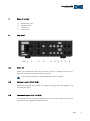
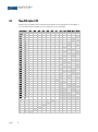
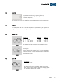
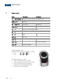
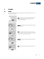
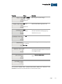
Series 7 soulution nature of sound Preamplifier 725 User manual Preamplifier 725 User manual Dear client We are proud that you decided yourself for a soulution preamplifier. You have acquired a preamplifier with outstanding sonic performance which you will enjoy for many years. We understand your eagerness to get started but even though please study this manual step by step before you integrate the preamplifier 725 in your High Fidelity system. This manual contains also useful tips for the optimisation of your overall HiFi-system. If there are any questions regarding the start-up or operation of your preamplifier 725 please do not hesitate to contact your dealer. Have fun! Your soulution team page 1 soulution nature of sound CE-Declaration of Conformity Spemot AG declares that this product is in conformance with the following directives and standards: Low Voltage Directive 2006/95/EG (EN/IEC 60065:2002) Electromagnetic Compatibility 2004/108/EG (EN 55013:2001, EN 55020:2002, EN 61000-3-2:2006, EN61000-3-3:1995) FCC-Notice Note: This equipment has been tested and found to comply with the limits for a Class B digital device, pursuant to Part 15 of the FCC Rules. These limits are designed to provide reasonable protection against harmful interference in a residential installation. This equipment generates, uses and can radiate radio frequency energy and, if not installed and used in accordance with the instructions, may cause harmful interference to radio communications. However there is no guarantee that interference will not occur in a particular installation. If this equipment does cause harmful interference to radio or television reception, which can be determined by turning the equipment off and on, the user is encouraged to try to correct the interference by one or more of the following measures: adjust or relocate the receiving antenna increase the separation between the equipment and the receiver connect the equipment into a mains outlet on a circuit different from that to which the receiver is connected consult the dealer or an experienced radio/TV technician for help Disposal According to the Directive 2002/96/EG of the European Parliament used consumer-electro technical appliances have to be disposed separately and have to be indicated with the following symbol. In the case of disposal of this component please do so in conformity with legal and environmental regulations. page 2 Preamplifier 725 User manual Table of contents 1 2 3 4 5 6 7 8 9 10 11 12 13 14 1 Quick start .......................................................................................... 3 Highlights ........................................................................................... 4 Safety advice: ................................................................................. 6 Scope of delivery ................................................................................. 7 Rear panel .......................................................................................... 7 Front panel ....................................................................................... 10 Remote control ................................................................................. 12 Programming .................................................................................... 13 Protection functions .......................................................................... 16 Trouble shooting ............................................................................... 17 Service ............................................................................................. 17 Warranty ........................................................................................... 18 Specifications ................................................................................... 19 Dimensions ....................................................................................... 20 Quick start Unpacking Unpack the preamplifier 725 Store the packing for future transportations Treat the surfaces with care Positioning Cabling Position the preamplifier 725 on a stable base. Cooling air must be able to escape unrestricted. Disconnect all components of your system from the mains Connect the preamplifier 725 with your amplifier Connect the 725 with your source components Connect all your components with the mains While manipulating with cables the 725 has to r emain disconnected from the mains. Settings Switch on Default values for all functions are programmed No additional settings are required. Switch-on the preamplifier 725 Select a moderate volume level Switch-on your source components and your amplifier Check the cabling before you switch-on page 3 soulution nature of sound 2 Highlights 2.1 Layout The preamplifier 725 is realised as unbalanced dual mono circuit. Left and right audio channels (incl. phono mc stage) each have identical circuit boards. Resulting in a channel separation of >105 dB, prerequisite for a three dimensional spatial reproduction. The audio section is physically separated from the power supply units and the digital circuits. For minimal interference the different sections are shielded against each other. 2.2 Volume control Relays switched high precision metal foil resistors form an 80 steps (1 dB) volume control. Each channel has its own volume control resistor network. The volume control allows also adjusting the balance. Depending on the balance setting the volume of the left or right channel is decreased. In order to avoid unpleasant click-noise and harmful voltage peaks while changing the volume the preamplifier 725 disposes over an additional volume control path only active while actually changing the volume. This parallel volume control is realised with a Programmable Gain Amplifier (PGA) which is able to adjust the volume without any noise. As soon as the new volume level is set the signal path is switched to the high end resistor network. 2.3 Phono-stage (optional) The phono stage has a basic amplification of +54 dB or +60 dB (at 1 kHz). This can be defined with the function Phono-Gain. The phono amplifier works with an internal bandwidth of 1 MHz (-3 dB). This guarantees the most accurate reproduction of the RIAA - equalisation curve. The impedance can be perfectly matched to your cartridge (10- 1’000) by dip switches at the back of the 725. page 4 Preamplifier 725 User manual 2.4 Output stage The output stage is optimised for velocity, precision and impulse current rating. Thanks to its low output impedance of 2 and Class-A operation (40mA idle current) the output stage is stable on every load (also long cables are driven without problems). The theoretical maximal current rating of 3 amperes is limited to 1 ampere. This is realised with a protection circuit outside the signal path. Due to the bandwidth of 1 MHz (-3 dB) - internally the output stage works up until frequencies of 40 MHz - all details of the music reproduced naturally. The spatial reproduction gets really three dimensional and holographic (optimal recording prerequisite). The power of the output stage ensures that all these details are truly transmitted to your amplifier. (Cable losses are minimised). 2.5 Power supply The preamplifier 725 has two separate power supply units, one for the supply of the audio section, another for the supply of the digital circuits. The stringent separation of the power supply units is amended with a multi stage filter network. Interference between digital and analogue circuits is thus minimised. The supply voltages for the audio section are multi stabilised. The precision and velocity of the voltage regulation could be further increased compared to the 720s power supply. More than 400’000 microFarad of capacitance ensures optimal impulse response of the powers supply. 2.6 Gain-adjustment Different signal sources typically have unequal output levels. For minimal volume differences while switching between inputs the preamplifier 725 allows adjusting the gain per input individually. This is implemented with an additional amplification stage adjustable for +3/+6/+9 dB and a level accuracy of 0.01 dB. page 5 soulution nature of sound 3 page Safety advice: 6 User manual Follow the safety advices Keep this user manual. Mains supply Exclusively use 3 phase power cords with ground conductor. Unplug the 725 from the mains in the following cases: before you manipulate with cables before cleaning during thunder storms before you leave for longer periods Cabling While manipulating with cables the 725 has to remain disconnected from the mains. Wrong cabling may cause damages to your 725, amplifier and loudspeakers. Excessive volumes due to inappropriate handling may cause hearing damages. Transport Use only with the cart, stand, tripod, bracket or table specified by the manufacturer or sold with the apparatus. When a cart is used, use caution when moving cart/apparatus combination to avoid injury or tip over. Packing In order to omit condensation of water inside preamplifier 725, let it warm up within the packing. Please keep the original packing for future transports. Operation Never run your preamplifier 725 with opened housing with closed cooling-slots with high ambient temperatures (>40°C) close to heat sources like radiators, etc. with extremely high humidity for example in humid cellars close to water (Sink, bathtub, or similar equipment) Cleaning Use a soft and dry towel. We suggest using a nonabrasive microfiber towel. Please do not use any solvents or liquidities Service Service by a qualified person required if the mains-cable or the mains connectors are damaged foreign substances or liquidity have entered the 725 the 725 has seen rain the 725 seems to malfunction the 725 has fallen to the floor or the housing is damaged Preamplifier 725 User manual 4 Scope of delivery 5 Preamplifier 725 Remote control Power cord User manual Rear panel I A 5.1 Mains (A) Connect the preamplifier 725 with the mains supply. In standby the 725 has a power consumption of <0.5W (red LEDs in display). Only switch-off the mains if your preamplifier 725 is in standby. 5.2 Balanced inputs IN 1/IN 2 (B) Please use top grade audio cables. For longer connecting cables we suggest using the balanced inputs. 5.3 Unbalanced inputs IN 4...IN 6 (D) The preamplifier 725 has three unbalanced inputs IN 4...IN 6. Connect your source components with top grade unbalanced cables. page 7 soulution nature of sound 5.4 Phono IN 3 (optional) (C) Connect your turntable with unbalanced connectors to the preamplifier 725 (MC only). The termination impedance can be adjusted to your cartridge. Impedance 1000 795 600 520 500 445 405 375 365 340 320 300 295 290 280 270 250 240 235 230 220 215 210 200 190 185 175 165 155 150 100 75 55 30 20 10 page 8 S1 S2 S3 S4 S5 S6 S7 S8 S9 S10 S11 S12 - - - - - - - - - - - - - - - - - - - - - - - - - - - - - - - - - - - - - - - - - - - - - - - - - - - - - - - - - - - - - - - - - - - - - - - - - - - - - - - - - - - - - - - - - - - - - - 1 - 1 - - - 1 1 - 1 - - - - 1 - 1 - - 1 - - - - - - 1 1 - - - - 1 - - 1 - - - - 1 1 1 - - - - 1 - 1 - - - - 1 - - - - - - - - - 1 - 1 1 - - - - - 1 1 - - - - - - - 1 - - - 1 - - - - - - - 1 1 - 1 - - - - - - 1 - - 1 - - - - - - - - - 1 1 1 - - - - - - - - 1 - - 1 1 - - - - - - - 1 - 1 - - - - - - - - - 1 - 1 - 1 - - - - - - 1 - - - - - - - - - - - - 1 1 - - - - - - - - - - 1 - 1 1 - - - - - - - - 1 - 1 1 1 - - - - - - - 1 1 - 1 - - - - - - - - 1 1 - 1 1 - - - - - - - 1 1 1 - 1 - - - - - - - 1 1 1 1 - - - - - - - - 1 1 1 1 1 - - - - - 1 - - - - - - - - - - 1 - - - - - - - - - - 1 - - - - - - - - - - 1 - - - - - - - - - - 1 - - - - - - - - - - 1 - - - - - - - - - - - Preamplifier 725 User manual Two gain levels can be selected for the phono stage: Low: +54dB @ 1kHz, High: +60dB @ 1 kHz If required the subsonic filter RIAA-IEC can be activated. Never connect a line source to the input IN 3. The phono stage is not protected against high voltages (for sonic reasons) and would be destroyed. 5.5 Main-Out (E) Due to the exceptional load stability there are no restrictions regarding the selection of your connecting cables. For long cable lengths we recommend using balanced cables. Gain (@ Volume 80) Balanced-Out (XLR) Unbalanced-Out (RCA) IN 1 & IN 2 IN 3 (gain low) IN 4 – IN 6 +9.5dB +3.5dB +63.5dB +57.5dB +9.5dB +3.5dB A potential humm loop can be suppressed with the Ground-Lift switch (XLR only). Ground-Lift 1 = ground connected Ground-Lift 0 = ground disconnected 5.6 LINK (F) The preamplifier 725 can control the start-up sequence of soulution components connected through the LINK System (cable: CAT 5, RJ45). The preamplifier 725 will trigger the switch on of connected components. It will remain protected until all connected components are switched on. The display shows LINK ERROR if a connected component does not switch on. 5.7 DC-Out (G) The ultra-stable power supply of the preamplifier 725 can be used for other for soulution components through the DC-OUT connector. Always switch off the 725 before you connect an external device. page 9 soulution nature of sound 5.8 RS232 – Interface (H) The preamplifier 725 can be remote controlled through the RS232 interface. All functions can be controlled and relevant information is provided to the control unit. 5.9 Type label (I) The type label shows the serial number and the nominal power consumption. 6 Front panel 6.1 Power (J) The Power-button defines the operating condition ON or OFF (red LEDs). The audio circuits remain disconnected from the outputs until it is switched on. Display in standby (OFF) Display for PROTECT ON Display for ON condition We suggest switching the 725 to standby (OFF) while not listening to music. (Power consumption <0.5 W). Unplug the 725 from the mains before you manipulate with cables, before cleaning, during thunder storms or before you leave for longer periods. Switch the preamplifier 725 to standby (OFF), before you unplug the mains. page 10 Preamplifier 725 User manual 6.2 Mute (K) Mute allows disconnecting all inputs from the outputs in case of an urgency (wrong cabling, feedback loops, etc.). For reducing the volume to a predefined level please use the function Volume-Dim. 6.3 Prog (L) The preamplifier 725 can be adjusted to specific requirements of your system. The Prog-button (de)activates the Programming-Mode. 6.4 Volume (M) Volume +/0 = 1 = 80 = Mute min. volume max. volume XLR out RCA out - ∞ dB -69.5 dB +9.5 dB - ∞ dB -75.5 dB +3.5 dB We suggest limiting the volume (Volume-Max function) Volume-Dim Pushing the Volume-knob (de)activates the Volume-Dim function (Display for example „D 10“).As long as the Volume-Dim function is active the volume cannot be altered by the Volume-knob. 6.5 Input (N) Input Select Selects the inputs All other inputs remain disconnected DC-protection function is activated while switching between inputs. If there is no DC-offset the coupling capacitor is bypassed after ca. 15 seconds. page 11 soulution nature of sound 7 Remote control Taste (1) Pre-Modus IR-transmitter Operation until 5m distance and angel of ±45°. (2,3) Volume +/- (4) Volume-Dim Play/Pause (5/6) Select +/- Next / Previous track (7) Enter Function for Program-Mode (8) P (De)activates Program-Mode DIM / (9) Mute (10) ON / OFF (11) - Open/Close (12) PRE - Activates PRE-Mode (13) CD Activates CD-Mode - Change of Remote Ctrl ID: Press the respective buttons for approx. 5 seconds. ID 1: (6), (5), (10) ID 2: (6), (5), (9) Exchange of batteries (2 x AAA): Open the battery tray on the rear side. Insert the batteries into the tray as indicated. Ensure correct polarity of the batteries. Close the tray with corresponding screw. Dispose the exhausted batteries page 12 CD-Modus - Preamplifier 725 User manual 8 Programming 8.1 Overview The available Program-Functions allow adjusting the preamplifier 725 to your individual High-Fidelity setup. Push on the Prog button switches the preamplifier 725 between operating-mode and programming-mode. Timeout after 10 seconds. . Rotating of the Select knob allows selecting the desired Program-Function Push on the Select knob for approval of the selected function. Now the value domain of the selected ProgramFunction is active. (red LEDs in display). Rotating of the Select knob allows for adjusting the desired value. Push on the Select knob for approval of the respective value. page 13 soulution nature of sound 8.2 Program-Functions Function Values Remarks IN 1, IN 2, IN 3, IN 4, IN 5, IN 6 Defines active input after switch on. 1..30..50 Defines volume level for switch-on. 1..20..40 Defines volume for DIM-function. 50...80 Defines maximal volume level <- 9...0...9 -> Sets balance between left and right channel OFF, CD, DAC, PHON, SACD, TUNE, etc. Renames the inputs IN 1...IN6 to your individual setup. Low = 20kHz Limits the bandwidth for the selected Mid = 200 kHz input IN 1...IN 6. High = 2 Mhz 0/+3/+6/+9 page 14 Sets additional gain per input. Preamplifier 725 User manual Function Value Remarks Low = 54dB High = 60dB (Optional) Defines gain of phono stage ON, OFF (De)activates RIAA high pass filer. (Optional) OFF, IN 1, In 2, IN3, IN 4, Defines the Surround-IN. Volume and balance settings get ignored for this input. 20..50..80 Defines volume for the Surround-IN. 1 = low 2 = medium 3 = high Sets the brightness of the display 1, 2 Deinfe the remote ctrl ID of the 725. The ID of the remote control unit has to be changed as well. Loads default values (bold) for all functions Shows firmware version. The functions PHONO GAIN, „PHONO HIGH PASS, NAME-IN 3, GAIN-IN 3 und BANDWIDTH-IN3 are only available for units with phono option. page 15 soulution nature of sound 9 Protection functions Comprehensive protection functions ensure a secure operation and long durability. The preamplifier 725 disposes over the following functions: Overcurrent: For currents > 1 Ampere at the Main-Out the preamplifier 725 shuts down automatically. DC-PROTECT: Your preamplifier 725 is protected against DC-offset at the inputs IN 1...IN 6. The input signal is permanently monitored for DC-components. As soon as a DC-offset is detected a coupling capacitor is switched into the signal path. This capacitor is bypassed if the DC-offset has ceased for at least 15 seconds. The display shows the symbol for the capacitor (╪). While switching between inputs the capacitor is activated automatically for security reasons. This is not a malfunction of your source device. Fuse: The mains connection has a fuse which protects your preamplifier 725 against too high power consumption. The fuse is located within the mains switch on the rear side of the preamplifier 720. Model 220-240 V, 50-60Hz Model 100-120 V, 50-60Hz page 16 2A/T 250V micro fuse 5x20mm 4A/T 250V micro fuse 5x20mm Preamplifier 725 User manual 10 Trouble shooting Error Action No Display Check the cabling to the mains supply. Eventually replace the fuse of your preamplifier 725. No music Check the following: cabling to your power amplifier, signal sources and from the power amplifier to your loudspeakers whether you have selected the correct input, the source device is muted if the power amplifier is switched on the LINK connection POWER FAIL If the power supply to the audio channels is interrupted or an error in the power supply unit has occurred the preamplifier 725 is shut down automatically. The display shows POWER FAIL. OVERCURRENT If the current at the Main-Out exceeds 1 ampere the preamplifier 725 is shut down automatically. The display shows OVERCURRENT. Check the cabling to the power amplifier. This error may also be provoked by defect or switched off power amplifier. If you con not identify the error please disconnect the mains supply (before you disconnect the preamplifier 725 has to be in operating condition OFF) and contact your soulution dealer. 11 Service If your soulution preamplifier needs service please contact your soulution dealer. For further information see www.soulution-audio.com page 17 soulution nature of sound 12 Warranty All soulution products are guaranteed against defects in material and workmanship for five years from date of purchase. The guarantee is void if the preamplifier 725 has been subject to misuse or negligence or has been modified, repaired or opened by a non authorised person without written authorisation of Spemot AG. For the return transport to our premises please use exclusively the original packaging. Transport damages are not subject to this guarantee, repairs will be charged. We recommend effecting transport insurance. If you not posses the original packaging no more please contact your soulution dealer. Basic repairs may be completed by your soulution dealer. Please clarify whether he is able to do the work before you send the preamplifier 725 back to us. page 18 Preamplifier 725 User manual 13 Specifications Data General Nominal voltage Nominal rating Power consumption Power consumption Line-inputs: Amplification Frequency response Slew rate THD+N Signal-to-Noise ratio Crosstalk Input impedance Phono-Input: Amplification Amplifier bandwidth Slew rate THD+N Input-Impedance Outputs Voltage Current Impedance LINK-Out Dimensions Dimensions Weight Model 220-240V Model 100–120V (OFF) (ON) IN 1/IN 2, IN 4...IN 6 symmetrical (IN 1/IN 2) asymmetrical (IN 4...IN 6) symmetrical (IN 1/IN 2) asymmetrical (IN 4...IN 6) 220 - 240 V, 50-60 Hz 100 – 120 V, 50-60 Hz 250 W <0.5 W 60 W +9.5...+18.5 dB +3.5...+12.5 dB DC-1 MHz 400 ns <0.0006 % 140 dB 105 dB 2 k 47 k IN 3 (optional) (internal) (adjustable) Main-Out symmetrical Main-Out asymmetrical Main-Out symmetrical Main-Out asymmetrical +54...+60 dB DC-1 MHz 400 ns <0.0006 % 10 – 1’000 max. max. max. 16 Vrms@100 8 Vrms@100 1A 2 2 +12 V 480x450x167 mm ca. 30 kg Technical specifications are subject to change without prior notification. page 19 soulution nature of sound 14 page Dimensions 20 Spemot AG Industriestrasse 70 CH-4657 Dulliken www.soulution-audio.com [email protected] soulution nature of sound part.no. 92182