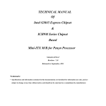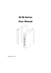
1
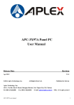
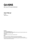
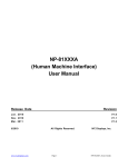
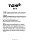
User Manual IMP-A080T / A100T Industrial Panel PC ___________________________________ Warning! ___________________________________ This equipment generates, uses and can radiate radio frequency energy and if not installed and used in accordance with the instructions manual may cause interference to radio communications. It has been tested and found to comply with the limits for a Class A computing device pursuant to FCC Rules, which are designed to provide reasonable protection against such interference when operated in a commercial environment. Operation of this equipment in a residential area is likely to cause interference in which case the user at his own expense will be required to take whatever measures may be required to correct the interference. Electric Shock Hazard – Do not operate the machine with its back cover removed. There are dangerous high voltages inside. Disclaimer This information in this document is subject to change without notice. In no event shall Indumicro.com be liable for damages of any kind, whether incidental or consequential, arising from either the use or misuse of information in this document or in any related materials. Table of Contents Chapter 1: Getting Started 1.1 Specifications…………………………………………………………………………..1 1.2 Dimensions…………………………………………………………………………….2 1.3 Brief Description of the IMP-A080T/A100T………………..………………………..6 Chapter 2: BIOS Setup 2.1 Operations after POST Screen..…....……………………..………………………..7 2.2 Standard CMOS Features..…………………………………………………………..9 2.3 Advanced BIOS Features..………………………………………………………….12 2.4 Advanced Chipset Features.………………………………………………………..15 2.5 Integrated Peripherals……………………………………………………………….19 2.6 Power Management Setup...………….……………………………………………24 2.7 PnP/PCI Configurations...………….……………………………………………….27 2.8 PC Health Status....………….………………………………………………………29 2.9 Load Fail-Safe/Optimized Defaults...………………………………………………30 2.10 Set Administrator/User Passwords.………………………………………………31 2.11 Save & Exit Setup……………….....………………………………………………32 2.Exit Without Saving…………………....………………………………………………32 Chapter 3: Installation 3.1 Configuring PenMount Windows 2000/XP/Vista/7 Driver …………...…………33 Chapter 4: Software 4.1 Software Functions…………...……………...………..……………………………42 4.2 Software Function Descriptions …………...……………...………..……………43 Appendices A Panelmounting … .………………………………………………………………….49 Chapter 1: Getting Started 1.1 Specifications Model Specs IMP-A080T IMP-A1 00T CPU Intel Atom N270 1.6 GHz processor with FSB 533 MHz Chipset Intel 945GSE+ Intel ICH7M BIOS Award 4 MB SPI BIOS System Memory Display Size Maximum Colors 1 x 200-pin DDR2 533 MHz SO-DIMM slot, up to 2 GB 8” 800x600 TFT 10.4” 800x600 TFT 262K 262K Viewing Angle (H/V) 130˚ /120˚ 130˚ /110˚ Luminance (cd/m²) 350 250 Backlight Lifetime 40,000 Hours Touch Screen Type Analog Resistive Serial Port 2 x RS-232 Port, 1 x RS-232/422/485 Port USB Port 4 x USB 2.0 Port LAN 2 x Gigabit LAN Audio MIC, Line-out Display Port VGA Expansion Slot None Storage 1 x 160GB HDD, 1 x CF slot (external) Power Supply 11~32 VDC Construction NEMA 4/IP65 certified front panel Rating Plastic molded front panel, steel housing Mounting Panel / VESA 75 Mount Dimensions (WxHxD) Weight 317 x 243 x 76 231 x 176 x 98 5.5kg 3.5kg Operating Temperature 0~50 ゚C Storage Temperature -20~60 ゚C Relative Humidity 10~90% (non-condensing) Vibration Shock Certificate IMP-A080T/A100T User Manual 5~17Hz, 0.1” double amplitude displacement / 17~640Hz, 1.5G acceleration peak to peak 10G acceleration peak to peak (11 millimeters) Meet CE / FCC Class A 1 Chapter 1: Getting Started 1.2 Dimensions Panel Cut-out Dimensions of the IMP-A080T IMP-A080T/A100T User Manual 2 Chapter 1: Getting Started Panel Cut-out Dimensions of the IMP-A100T IMP-A080T/A100T User Manual 3 Chapter 1: Getting Started 1.3 Brief Description of the IMP-A080T/A100T The power-optimized IMP-A080T and IMP-A100T systems deliver robust performance-per-watt as an embedded HMI. The systems are powered by an Intel Atom™ N270 1.6 GHz processor. They come with a CompactFlash slot, 2.5" hard disk drive, DDR2 memory, 3 serial ports, 4 USB ports, 2 Gigabit LAN ports, audio and DC input. These compact and fanless touch panel computer is ideal for panel comuters are ideal for use as a Web Browser, Terminal and HMI at all levels of automation control. Front view of the IMP-A080T/A100T Rear view of the IMP-A080T IMP-A080T/A100T User Manual Rear view of the IMP-A100T 4 Chapter 2: BIOS Setup 2.1 Operations after POST Screen After CMOS discharge or BIOS flashing operation, the system will display the following screen for your further operation. Press F1 key to continue or Del key to enter CMOS Setup. Phoenix – AwardBIOS v6.00PG, An Energy Star Ally Copyright © 1984-2007, Phoenix Technologies, LTD ASB-L701 V012 Main Processor : Intel® Atom™ 1.60GHz(133x12) Memory Testing :515008K OK + 8M shared memory CPU Brand Name : Intel® Atom™ CPU N270 @1.60GHz C1E BIOS Supported Hyper-Threading Technology CPU Detected (Hyper-Threading Technology Enabled) Memory Frequency For DDR2 533 IDE Channel 0 Master : None IDE Channel 0 Slave : None IDE Channel 1 Master : None IDE Channel 1 Slave : None CMOS checksum error – Defaults loaded Press F1 to continue, DEL to enter SETUP 11/25/2009-Silverthrone-6A79KAPXC-00 After optimizing and exiting CMOS Setup, the POST screen displayed for the first time is as follows and includes basic information on BIOS, CPU, memory, and storage devices. IMP-A080T/A100T User Manual 5 Chapter 2: BIOS Setup Phoenix – AwardBIOS v6.00PG, An Energy Star Ally Copyright © 1984-2007, Phoenix Technologies, LTD ASB-L701 V012 Main Processor : Intel® Atom™ 1.60GHz(133x12) Memory Testing :515008K OK + 8M shared memory CPU Brand Name : Intel® Atom™ CPU N270 @1.60GHz C1E BIOS Supported Hyper-Threading Technology CPU Detected (Hyper-Threading Technology Enabled) Memory Frequency For DDR2 533 IDE Channel 0 Master : None IDE Channel 0 Slave : None IDE Channel 1 Master : None IDE Channel 1 Slave : None Press DEL to enter SETUP, F12 to Enter Boot Menu 11/25/2009-Silverthrone-6A79KAPXC-00 Press F12 key to enter Boot Menu during POST, as shown by the following figure. Boot Menu == Select a Boot First device == + Removable + Hard Disk + CDROM LAN ↑↓:Move Enter:Accept F4:Exit IMP-A080T/A100T User Manual 6 Chapter 2: BIOS Setup 2.2 Standard CMOS Features Press [Del] key to enter BIOS Setup utility during POST, and then a main menu containing system summary information will appear. Phoenix – AwardBIOS CMOS Setup Utility Standard CMOS Features Load Fail-Safe Defaults Advanced BIOS Features Load Optimized Defaults Advanced Chipset Features Set Administrator Password Integrated Peripherals Set User Password Power Management Setup Save & Exit Setup PnP/PCI Configurations Exit Without Saving PC Health Status ESC : Quit F10 : Save & Exit Setup : Select Item Time, Date, Hard Disk Type . . . Standard CMOS Features Use this menu to modify basic system configurations such as time, date and etc. Advanced BIOS Features Use this menu configure advanced features of Award® BIOS. Advanced Chipset Features Use this menu to change the values in the chipset registers and optimize your system performance. Integrated Peripherals Use this menu to specify your settings for integrated peripherals. Power Management Setup Use this menu to specify your settings for power management. PnP/PCI Configurations This menu is valid only if your system supports PnP/PCI. PC Health Status This menu shows the current status of your PC. IMP-A080T/A100T User Manual 7 Chapter 2: BIOS Setup Load Fail-Safe Defaults Use this menu to load Fail-Safe defaults into BIOS for the most stable, and minimal-performance system operations. Load Optimized Defaults Use this menu to load factory settings into BIOS for optimal-performance system operations. Set Administrator Password Use this menu to set Administrator password. Set User Password Use this menu to set user password. Save & Exit Setup Save all changes to the CMOS and exit BIOS Setup. Exit Without Saving Abandon all changes to the CMOS and exit BIOS Setup. The following figure shows the items of Standard CMOS Features menu, which may exclude any modifiable subitem or contain one or more modifiable subitems. Use arrow keys to select the items to be modified and <PgUp> or <PgDn> key to select desired settings. Phoenix – AwardBIOS CMOS Setup Utility Standard CMOS Features Date (mm:dd:yy) Time (hh:mm:ss) IDE Channel 0 Master IDE Channel 0 Slave IDE Channel 1 Master IDE Channel 1 Slave Video Halt On Base Memory Extended Memory Total Memory Thu, Dec 23 2009 20 : 11 : 17 Item Help Menu Level [ None] [ None] [ None] [ None] [EGA/VGA] [All, But Keyboard] 639K 1038336K 1039360K Change the day, month, year and century :Move Enter: Select +/-/PU/PD:Value F10:Save ESC:Exit F1:General Help F5: Previous Values F6: Fail-Safe Defaults F7: Optimized Defaults IMP-A080T/A100T User Manual 8 Chapter 2: BIOS Setup Date This item allows you to set a desired system date (usually current date). The date format is <day><month><date><year>. Day It is a read-only and bios-defined weekday attribute ranging from Sun (Sunday) to Sat (Saturday). Month It is a month attribute ranging from Jan (January) to Dec (December). Date It is a date attribute ranging from 1 to 31 and can be modified via numeric keys. Year It is a user-defined year attribute. Time This item allows you to set a desired system time (usually current time). The time format is <hour><minute><second>. Channel 0 Master / Channel 0 Slave Channel 1 Master / Channel 1 Slave Press PgUp/<+> or PgDn/<-> key to select among Manual, None and Auto type. Note that the specification of your drive device must be in compliance with the contents of Drive Table. If the information registered in this item is not correct, your hard disk will not work properly; if your hard disk specification is not found or does not conform to or the Driver Table, you may select Manual type to set the specification manually. If you choose Manual, you will be requested to enter relevant information in the following entries. Keyboard input is also supported. For details, you may refer to the instructive materials provided by distributor or device manufacturer. If a SCSI HDD device is used, set this item to "NONE". If a CD-ROM drive is connected to the HDD port, set this item to "NONE" AccessMode Cylinder Head Precomp Landing Zone Options are: Auto, Normal, Large and LBA Number of cylinders Number of heads Write precompensation cylinder Head landing zone Halt on The item allows you to determine when the system will stop. Options are: No Errors; All Errors; All, But Keyboard No Errors The system boot will not stop for any error. All Errors Whenever the BIOS detects a non-fatal error, the system boot will stop. All, But Keyboard The system boot will not stop for a keyboard error but stop for all other errors as detected by BIOS. (default) IMP-A080T/A100T User Manual 9 Chapter 2: BIOS Setup 2.3 Advanced BIOS Features Phoenix – AwardBIOS CMOS Setup Utility Advanced BIOS Features CPU Feature Hard Disk Boot Priority Virus Warning CPU L1 & L2 Cache Hyper-Threading Technology Quick Power On Self Test First Boot Device Second Boot Device Third Boot Device Boot Other Device PXE Boot For Onboard LAN1 PXE Boot For Onboard LAN2 Boot Up NumLock Status Gate A20 Option x APC Mode MPS Version Control For OS OS Select For DRAM > 64MB Small Logo(EPA) Show Security Option [Press Enter] [Press Enter] [Disabled] [Enabled] [Enabled] [Enabled] [CDROM] [Hard Disk] [LAN] [Enabled] [Disabled] [Disabled] [On] [Fast] Enabled [1.4] [Non-OS2] [Disabled] [Setup] Item Help Menu Level :Move Enter: Select +/-/PU/PD:Value F10:Save ESC:Exit F1:General Help F5: Previous Values F6: Fail-Safe Defaults F7: Optimized Defaults CPU Feature The item has the following options: Delay Prior To Thermal [16 Min] (This item allows you to set the duration of entering CPU thermal throttling.) C1E Function [Auto] CPU Power-saving State Enable Control CPU C State Capability [C1] Execute Disable Bit [Enable] CPU Power-saving State Control Virus Protection Technology Hard Disk Boot Priority (IDE Storage Device Boot Priority) This item is used to specify boot priority of IDE devices. Press "Enter" key for detailed setting. Virus Warning This item has two options: "Disabled" and "Enabled". IMP-A080T/A100T User Manual 10 Chapter 2: BIOS Setup CPU L1 & L2 Cache This item can be used to enable or disable the CPU’s primary (L1) or secondary (L2) cache. If set to Enabled, operating speed of PC will be increased remarkably; if set to Disabled, the function will be inactivated. Hyper-Threading Technology Enable and disable Intel's hyper-threading technology. Quick Power On Self Test This item is used to accelerate Power On Self Test (POST) process. If set to Enabled, BIOS will shorten or skip some of its tests. Enabled (default) Quick POST Disabled Normal POST First/Second/Third/Boot Other Device BIOS will load the operating system according to the boot order of available devices. If disabled, the function will be inactivated. Boot Up NumLock Status (Default: On) On (default) Keypad numeric keys remain valid Off Keypad arrow keys remain valid Gate A20 Option Normal Gate A20 signal is controlled by keyboard controller or chipset hardware Fast (default) Gate A20 signal is controlled by port 92 or specific programs of chipset. APIC Mode It refers to an advanced interrupt controller mode to meet the requirements of multi-core CPU. MPS Version Control For OS This item is used to specify the multiprocessor specification version of the system. It is recommended to keep the default value (1.4). OS Selection for DRAM > 64MB You must only select OS/2 when installing an OS/2 operating system with a RAM greater than 64MB. The options are: Non-OS/2 (default) and OS/2. Small Logo [EPA] Show This item is used to determine whether the Energy Star Logo will be displayed during POST. The options are: "Disabled" and "Enabled". IMP-A080T/A100T User Manual 11 Chapter 2: BIOS Setup Security Option Such option allows users to set access restrictions to both system and Setup utility, or just Setup utility. System If one fails to enter a valid password in the popup box, the system will not boot up and the Setup utility will not be accessible. Setup (default) If one fails to enter a valid password in the popup box, the system will boot up as usual, but the Setup utility will not be accessible. IMP-A080T/A100T User Manual 12 Chapter 2: BIOS Setup 2.4 Advanced Chipset Features Setup Advanced Chipset Features Setup is used to change the values of chipset registers that control most options of computer. Select ADVANCED CHIPSET FEATURES in the main menu, and the following screen will be displayed. Phoenix – AwardBIOS CMOS Setup Utility Advanced Chipset Features DRAM Timing Selectable x CAS Latency Time x DRAM RAS# to CAS# Delay x DRAM RAS# Precharge x Precharge Delay (tRAS) x System Memory Frequency SLP_S4# Assertion Width System BIOS Cacheable Video BIOS Cacheable Memory Hole At 15M-16M PCI Express Root Port Func ** Onboard VGA Setting ** On-Chip Frame Buffer Size DVMT Mode DVMT/FIXED Memory Size Boot Display LCD Panel Type LCDS Panel Brightness [By SPD] Auto Auto Auto Auto Auto [ 1 to 2 Sec.] [Enabled] [Disabled] [Disabled] [Press Enter] [ 8MB] [DVMT] [ 128MB] [VGA + LVDS] [LVDS 18 800x600] [Level 10] Item Help Menu Level :Move Enter: Select +/-/PU/PD:Value F10:Save ESC:Exit F1:General Help F5: Previous Values F6: Fail-Safe Defaults F7: Optimized Defaults Note: If you are not familiar with chipset, never modify these settings at will. DRAM Timing Selectable Two options are available. Manual Manual setup By SPD DRAM timing is set automatically according to memory SPD data When selecting Manual, the following five items are configurable; when selecting By SPD, the following five items are not configurable. CAS Latency Time Once a SDRAM is installed, the clock latency will be determined by DRAM clock settings. The options are: 5, 4, 3 and Auto. IMP-A080T/A100T User Manual 13 Chapter 2: BIOS Setup DRAM RAS-to-CAS Delay You may set the delay period between CAS and RAS signal for DRAM read & write or refreshing. Shorter delay means quicker response, while longer delay means more stable performance. Options are: 2, 3, 4, 5, 6 and Auto. DRAM RAS Precharge If number of cycles is not sufficient enough to ensure that RAS saves its instructions before DRAM refreshing, it may cause incomplete refreshing and the DRAM will fail to maintain its data. Faster precharge means quicker response, while slower precharge means more stable performance. This item is only valid when a SDRAM is installed. Options are: 2, 3, 4, 5, 6 and Auto. Precharge Delay (t RAS) Options are: Auto and 4~15. System Memory Frequency Options are: Auto, 533 and 667(MHz). SLP_S4# Assertion Width Four options are available: 4 to 5 Sec. 3 to 4 Sec. 2 to 3 Sec. 1 to 2 Sec. System BIOS Cacheable If set to Enabled, the feature will enable the caching of BIOS ROM at F0000h-FFFFFh for better system performance. However, if any program writes into this memory area, it will result in a system error. Options are: Enabled and Disabled. Video BIOS Cacheable If set to Enabled, the feature will enable the caching of video BIOS ROM for better system performance. However, if any program writes into this memory area, it will result in a system error. Options are: Enabled and Disabled. Memory Hole At 15M-16M This feature will decrease your memory by 1M and allow the few old ISA cards that require this memory to work properly on your system. Options are: Enabled and Disabled. PCI Express Root Port Func This item is used to configure PCI-E slot. For motherboards not equipped with PCI-E slot, such configuration is not required. If set to Disabled, the slot and slot device will be disabled. For example, onboard network adapter card can be disabled or enabled via PCI-E slot 1. IMP-A080T/A100T User Manual 14 Chapter 2: BIOS Setup On-Chip Frame Buffer Size This feature controls the amount of video memory allocated to integrated graphic card. The system memory can be used as video memory. DVMT Mode Three options are available: "FIXED", "DVMT" and "Both (FIXED+DVMT)". When set to "FIXED" mode, a fixed portion of the system memory will be allocated to GPU. Two allocation sizes are available: 64MB and 128MB. When set to "DVMT" Mode, the system will dynamically allocate system memory to GPU. In this mode, up to 224MB of system memory can be allocated. When set to "Both(FIXED+DVMT)" mode, the system will allocate a fixed memory of 64MB as dedicated graphic memory, as well as allow a memory of 64MB to be dynamically allocated between GPU and operating system. DVMT/FIXED Memory Size Refer to the previous item. Boot Display This feature is to select desired display device. VBIOS, LVDS1, VGA+LVDS1, LCDS2 and VGA+LVDS2 can be selected as display device. LCD Panel Type (LVDS Panel Type) This feature is to select between LVDS1 and LVDS2. When selecting LVDS panel, users should be informed of LVDS panel types supported by the motherboard. The following options are available: LVDS1 18 LVDS1 18 LVDS1 18*2 LVDS1 18*2 LVDS1 18*2 LVDS1 18*2 LVDS1 18 LVDS1 18 LVDS2 24 LVDS2 24*2 LVDS2 24*2 LVDS2 24*2 800X600 1024X768 1280X1024 1440X900 1400X1050 1600X1200 1280X800 1280X768 1024X768 1280X1024 1440X900 1920X1080 Note: Due to limited address length of BIOS, only a portion of panel parameters are listed in BIOS Setup. If the connected panel is not included in the parameter list, display problem will occur in this case, we need to adjust BIOS setup. IMP-A080T/A100T User Manual 15 Chapter 2: BIOS Setup LVDS1 Panel Brightness This feature provides adjustable brightness control: LEVEL3~10. Note: This feature is valid only when the panel supports PWM function. IMP-A080T/A100T User Manual 16 Chapter 2: BIOS Setup 2.5 Integrated Peripherals Phoenix – AwardBIOS CMOS Setup Utility Integrated Peripherals OnChip IDE Device Onboard Device Super IO Device [Press Enter] [Press Enter] [Press Enter] Item Help Menu Level :Move Enter: Select +/-/PU/PD:Value F10:Save ESC:Exit F1:General Help F5: Previous Values F6: Fail-Safe Defaults F7: Optimized Defaults Select "OnChip IDE Device" item and press "Enter" for setup of IDE devices, as shown by the following figure: Phoenix – AwardBIOS CMOS Setup Utility On-Chip IDE Device IDE HDD Block Mode IDE DMA Transfer Access On-Chip Primary PCI IDE IDE Primary Master PIO IDE Primary Slave PIO IDE Primary Master UDMA IDE Primary Slave UDMA On-Chip Secondary PCI IDE IDE Secondary Master PIO IDE Secondary Slave PIO IDE Secondary Master UDMA IDE Secondary Slave UDMA x x x x [Enabled] [Enabled] [Enabled] [Auto] [Auto] [Auto] [Auto] [Enabled] [Auto] [Auto] [Auto] [Auto] ** On-Chip Serial ATA Setting ** SATA Mode IDE On-Chip Serial ATA [Auto] SATA Port Speed Settings Disabled PATA IDE Mode Secondary SATA Port P0, P2 is primary Item Help Menu Level If your IDE hard drive supports block mode select Enabled for automatic detection of The optimal number of block read/writes per sector the drive can support :Move Enter: Select +/-/PU/PD:Value F10:Save ESC:Exit F1:General Help F5: Previous Values F6: Fail-Safe Defaults F7: Optimized Defaults IMP-A080T/A100T User Manual 17 Chapter 2: BIOS Setup IDE HDD Block Mode If your IDE hard disk supports Block mode (most current hard disk products support the feature), select Enabled and BIOS will automatically detect optimum block mode supported by the hard disk. This will improve the transfer performance of hard disk. Options are: Enabled (default) and Disabled. IDE DMA Transfer Access Options are: Enabled (default) and Disabled. On-Chip Primary/Secondary PCI IDE Each IDE port of integrated peripheral controller supports up to 2 IDE channels. Select Enabled to activate each channel. Options are: Enabled (default) and Disabled. IDE Primary /Secondary Master/Slave PIO The four IDE PIO (Programmed Input/Output) fields allow you to set a PIO mode (0-4) for each of the four IDE devices that the onboard IDE interface supports. Mode 0 through 4 provides successively increased performance. In Auto mode, the system automatically determines the best mode for each device. Options are: Auto (default), Mode 0, Mode 1, Mode 3 and Mode 4. IDE Primary /Secondary Master/Slave UDMA Ultra DMA implementation is possible only if your IDE hard disk supports it and the operating environment includes a DMA driver (Windows 95 OSR2 or a third-party IDE bus mastering driver). If your hard disk and system software both support Ultra DMA/33, Ultra DMA/66 and Ultra DMA/100, select Auto to enable BIOS support. Options are: Enabled (deafult) and Disabled. On-Chip Serial ATA The following five options are available: Disabled Disable SATA controller Auto (default) Combined Mode Enhanced Mode Allocate SATA/IDE devices automatically IDE+SATA Combo Mode SATA Only SATA PORT Speed Setting Three options are available: Disabled (default) Disables the feature Force GEN I Enhance transfer speed to 1.5Gb/s, i.e., 150MB/s Enhance transfer speed to 3.0Gb/s, i.e., 300MB/s Force GEN II PATA IDE Mode The item allows you to configure PATA IDE mode. Setup option: Primary (default) and Secondary IMP-A080T/A100T User Manual 18 Chapter 2: BIOS Setup Select "Onboard Device" item and press "Enter" for setup of onboard devices, as shown by the following figure: Phoenix – AwardBIOS CMOS Setup Utility Onboard Device USB Controller USB 2.0 Controller USB Keyboard Support USB Moue Support Azalia/AC97 Audio Select [Enabled] [Enabled] [Enabled] [Enabled] [Auto] Item Help Menu Level :Move Enter: Select +/-/PU/PD:Value F10:Save ESC:Exit F1:General Help F5: Previous Values F6: Fail-Safe Defaults F7: Optimized Defaults USB Controller This item allows you to enable or disable onboard USB controller. Options are: Enabled (default) and Disabled. USB 2.0 Controller This item allows you to enable or disable USB 2.0 feature of onboard USB controller. Options are: Enabled (default) and Disabled. USB Keyboard Support This item determines if USB keyboard is supported in MS-DOS. Options are: Enabled (default) and Disabled. USB Mouse Support This item determines if USB mouse is supported in MS-DOS. Options are: Enabled (default) and Disabled. Azalia/AC97 Audio Select This item is used to select Audio mode. IMP-A080T/A100T User Manual 19 Chapter 2: BIOS Setup Select "Super IO Device" item and press "Enter" for setup of Super IO devices, as shown by the following figure: Phoenix – AwardBIOS CMOS Setup Utility Super IO Device x x x x x Onboard Parallel Port Parallel Port Mode ECP Mode Use DMA Onboard Serial Port 1 Onboard Serial Port 2 UART2 Mode Select RxD , TxD Active IR Transmission Delay UART2 Duplex Mode Use IR Pins Onboard Serial Port 3 Onboard Serial Port 4 [378/IRQ7] [Standard] 3 [3F8/IRQ4] [2F8/IRQ3] [Normal] Hi, Lo Enabled Half IR-Rx2Tx2 [3E8/IRQ4] [2E8/IRQ3] Power On by PS/2 Keyboard Watch Dog Timer Select [Disabled] [Disabled] Item Help Menu Level :Move Enter: Select +/-/PU/PD:Value F10:Save ESC:Exit F1:General Help F5: Previous Values F6: Fail-Safe Defaults F7: Optimized Defaults Onboard Parallel Port This item allows you to determine the I/O address and corresponding interrupts for the onboard parallel port LPT. Options are: Disabled, 378/IRQ7 (default), 278/IRQ5 and 3BC/IRQ7. Onboard Serial Port 1/2/3/4 These four selection fields allow you to select the I/O address and corresponding interrupts for serial port COM1/2/3/4. Options are: Disabled, 3F8/IRQ4 (default), 2F8/IRQ3, 3E8/IRQ4 and 2E8/IRQ3. UART Mode Select Generally, Onboard Serial Port 2 of motherboard can also be used as infrared port. This item allows you to determine whether Onboard Serial Port 2 is used as normal serial port or infrared port. Four options are available: Normal (default) Used as serial port IrDA Used as standard infrared port ASKIR Used as responder infrared port IMP-A080T/A100T User Manual 20 Chapter 2: BIOS Setup UR2 Duplex Mode This item will be set to Half Duplex (Half) mode unless your infrared device supports Full Duplex (Full) mode. Power On By PS/2 Keyboard Three options are available: Disabled (default) Any key Keyboard 98 Watch Dog Timer Select Eight options are available: Disabled (default), 10Sec, 20Sec, 30Sec, 40Sec, 1Min, 2Min and 4Min IMP-A080T/A100T User Manual 21 Chapter 2: BIOS Setup 2.6 Power Management Setup Power Management Setup allows you to configure your system to ensure an enhanced power-saving effect when user is compliant with system mode. Phoenix – AwardBIOS CMOS Setup Utility Power Management Setup Power Status After AC Fail ACPI Function Power Management Video Off Method Video Off In Suspend Suspend Type Modem Use IRQ Suspend Mode HDD Power Down Soft-Off by PWR-BTTN Resume by Alarm x Date(of Month) Alarm x Time(hh:mm:ss) Alarm [Turn On] [Enabled] [User Define] [DPMS] [Yes] [Stop Grant] [3] [Disabled] [Disabled] [Instant-Off] [Disabled] 0 0 : 0: 0 ** Reload Global Timer Events ** Primary IDE 0 [Disabled] Primary IDE 1 [Disabled] Secondary IDE 0 [Disabled] Secondary IDE 1 [Disabled] FDD, COM, LPT Port [Disabled] PCI PIRQ[A-D]# [Disabled] Item Help Menu Level :Move Enter: Select +/-/PU/PD:Value F10:Save ESC:Exit F1:General Help F5: Previous Values F6: Fail-Safe Defaults F7: Optimized Defaults PWR Status After PWR Fail Three options are available: Former Status (default) Turn On Keep Off Restore to former status Start up when power is restored Remain powered off ACPI Function This item allows you to enable/disable ACPI functions. Options are: Enabled (Default) and Disabled. Power Management This category allows you to select the type (or degree) of power saving and gives you direct assess to the following modes: 1. Suspend Mode 2. HDD Power Down IMP-A080T/A100T User Manual 22 Chapter 2: BIOS Setup Three options are available for Power Management, including two fixed modes. User Define (default) Min Saving Max Saving Allows you to set each mode individually. When not disabled, each of the ranges is from 1min to 15min. Minimum power management. Suspend Mode=1hr and HDD Power Down=15min. Maximum power management. Suspend Mode=1min and HDD Power Down=1min. Video Off Method This item determines the display type of monitor. V/HSYNC+Blank This option turns off the vertical and horizontal synchronization ports and writes blanks to the video buffer. Blank Screen This option only writes blanks to the video buffer. DPMS (default) This option controls initial display of power management signal. Video Off In Suspend This item determines the display type to be cleared by monitor. Options are: Yes (default) and No. Suspend Type This item is used to select suspend type. Options are: PWRON Suspend and Stop Grant (default). Modem Use IRQ This item determines the IRQ used by Modem. Options are: 3 (default), 4, 5, 67, 9, 10, 11 and NA. Suspend Mode When enabled, after the set time of system inactivity, all devices except the CPU will be shut off. Options are: 1/2/4/8/12/20/30/40Min, 1Hour and Disabled.(default) HDD Power Down When enabled and after the set time of system inactivity, the hard disk will be powered down while all other devices remain active. Options are: 1/2/3/4/5/6/7/8/9/10/11/12/13/14/15Min and Disabled (default). Soft-Off by PWR-BTTN Pressing the power button for more than 4 seconds forces the system to enter the Soft-Off state. Options are: Delay4Sec and Instant-Off (default). IMP-A080T/A100T User Manual 23 Chapter 2: BIOS Setup Wake-Up by PCI card This item allows the system to be awakened by peripheral device connected to PCI card. Options are: Enabled and Disabled. Power On by Ring When set to Disabled, the system will ignore any incoming Modem ring; when set to Enabled, the system will be automatically started up in case of incoming Modem ring. Resume by Alarm This feature determines whether to power on the system at a desired time. When set to Disabled, the feature is inactivated; when set to Enabled (default) date and time of power on can be set: Date(of month) Alarm Turn on the system at a specific time on each day or on a specific day in a month. If set to 0 (default) the system will be powered on once every day. Time(hh:mm:ss) Alarm Set the time (hh:mm:ss) at which the system will be powered on automatically. Note: You must restart the system after changing relevant settings, or the setting may not be effective. ** Reload Global Timer Events ** This module contains six modules, all of which are provided with two options: Enable and Disable. If set to Enable, the system will be awakened from sleep status when specific event occurs. IMP-A080T/A100T User Manual 24 Chapter 2: BIOS Setup 2.7 PnP/PCI Configurations Setup This part describes configurations to be made on PCI bus system. PCI, namely Personal Computer Interconnect, is a computer bus that allows I/O device to operate nearly as fast as CPU in its own way. Some technical terms will be mentioned here. We recommend that non-professional users not make changes from factory default settings. Phoenix – AwardBIOS CMOS Setup Utility PnP/PCI Configurations Init Display First Reset Configuration Data Item Help [PCI Slot] [Disabled] Menu Level Resources Controlled By [Auto(ESCD)] x IRQ Resources Press Enter PCI/VGA Palette Snoop [Disabled] ** PCI Express relative items ** Maximum Payload Size [128] :Move Enter: Select +/-/PU/PD:Value F10:Save ESC:Exit F1:General Help F5: Previous Values F6: Fail-Safe Defaults F7: Optimized Defaults Init Display First Three options are available: PCI Slot (default) Onboard PCiEx PCI display device Onboard display device PCIE device) Reset Configuration Data Normally, you should set this item to Disabled. If you have installed a new add-on and the system reconfiguration has caused such a serious conflict that the operating system cannot boot up, then select Enabled. This will reset the Extended System Configuration Data (ESCD) after exiting from Setup. Options are: Enabled and Disabled (default). IMP-A080T/A100T User Manual 25 Chapter 2: BIOS Setup Resource Controlled By Award Plug and Play BIOS has the capacity to automatically configure all of the boot and Plug and Play compatible devices. However, this capability means absolutely nothing unless you are using a Plug and Play operating system such as Windows®95/98. If set to Manual, you may have access into each submenu under this item (each submenu begins with "¾") and select specific resource manually. Options are: Auto(ESCD) (default) and Manual. IRQ Resources This item determines whether IRQ interrupt is assigned to Plug-and-Play device or Non-Plug-andPlay ISA device. PCI/VGA Palette Snoop This item should be left Disabled. Options are: Enabled and Disabled (default). ** PCI Express Relative Items ** Maximum Payload Size [128] This item allows you to configure maximum payload size of TLP (Transition Layer Packet). Options are: [128] (default), [256], [512], [1024], [2048] and [4096]. IMP-A080T/A100T User Manual 26 Chapter 2: BIOS Setup 2.8 PC Health Status This item shows the current operation status of system. Phoenix – AwardBIOS CMOS Setup Utility PC Health Status ** Smart Fan Control (Thermal Cruise) ** CPU Fan Cruise Target [65oC/149oF] [± 5oC] Fan Cruise Treshold ACPI Shutdown Temperature [Disabled] Item Help Menu Level x x x x x x x ** Onboard Health Sensor Status ** Current System Temperature 47oC/ 116oF Current CPU Temperature 39oC/ 102oF CPU Fan Speed 0 RPM Vcore(V) 1.19V 5Vcc (V) 5.10V Vbat (V) 3.40V 5Vsb (V) 5.09V :Move Enter: Select +/-/PU/PD:Value F10:Save ESC:Exit F1:General Help F5: Previous Values F6: Fail-Safe Defaults F7: Optimized Defaults This module mainly shows motherboard information on current operating voltage, CPU temperature, system temperature and fan rotation speed. Refer to actual screen for name of each column. CPU Fan Cruise Target/Fan Cruise Threshold: This item determines the rotation condition of fan when CPU temperature reaches preset value. Options of CPU Fan Cruise Target are: Disable, 55oC/131oF, 60oC/140oF and 65oC/149oF (default). Options for Fan Cruise Threshold are: ±2oC, ±3oC, ±4oC and ±5oC (default). For example, set CPU Fan Cruise Target to <65oC/149oF> and Fan Cruise Threshold to <±5oC>. When CPU temperature rises to 70oC (65oC+5oC, the fan will begin to rotate; when CPU temperature drops to 60oC (65oC-5oC, the fan will stop rotating. IMP-A080T/A100T User Manual 27 Chapter 2: BIOS Setup 2.9 Load Fail-Safe/Optimized Defaults These two items allow users to load fail-safe or optimized defaults to restore BIOS. Optimized defaults refer to the specific values set by motherboard manufacturer for optimized performance, while fail-safe defaults stand for settings made by BIOS distributor for stable performance. Fail-Safe Defaults, the following information will be shown: If you select Load Phoenix – AwardBIOS CMOS Setup Utility Standard CMOS Features Load Fail-Safe Defaults Advanced BIOS Features Load Optimized Defaults Advanced Chipset Features Set Administrator Password Integrated Peripherals Set User Password Power Management Setup Save & Exit Setup PnP/PCI Configurations Exit(Y/N): Without Load Fail-Safe Defaults N Saving PC Health Status ESC : Quit F10 : Save & Exit Setup : Select Item Load Fail-Safe Defaults Press Y to load BIOS defaults for stable, but lower performance. If you select Load Optimized Defaults, the following information will be shown: Phoenix – AwardBIOS CMOS Setup Utility Standard CMOS Features Load Fail-Safe Defaults Advanced BIOS Features Load Optimized Defaults Advanced Chipset Features Set Administrator Password Integrated Peripherals Set User Password Power Management Setup Save & Exit Setup PnP/PCI Configurations Exit (Y/N): Without Load Optimized Defaults N Saving PC Health Status ESC : Quit F10 : Save & Exit Setup : Select Item Load Optimized Defaults Press Y to load factory settings delivering optimized performance. IMP-A080T/A100T User Manual 28 Chapter 2: BIOS Setup 2.10 Set Administrator/User Password When selecting this feature, the following information will be shown: Phoenix – AwardBIOS CMOS Setup Utility Standard CMOS Features Load Fail-Safe Defaults Advanced BIOS Features Load Optimized Defaults Advanced Chipset Features Set Administrator Password Integrated Peripherals Set User Password Power Management Setup Save & Exit Setup PnP/PCI Configurations Enter Password: Exit Without Saving PC Health Status ESC : Quit F10 : Save & Exit Setup : Select Item Change/Set/Disable Password Type the password with up to 8 characters and then press the <Enter> key. This will clear all previously typed CMOS passwords. You will be requested to confirm the password. Type the password again and press the <Enter> key. You may press <Esc> to abandon password entry operation. To clear the password, just press the <Enter> key when password input window pops up. A confirmation message will be shown on the screen as to whether the password will be disabled. You will have direct access to BIOS setup without typing any password after system reboot once the password is disabled. Once the password feature is used, you will be requested to type the password each time you enter BIOS setup. This will prevent unauthorized persons from changing your system configurations. Also, the feature is capable of requesting users to enter the password prior to system boot to control unauthorized access to your computer. Users may enable the feature in Security Option of Advanced BIOS Features. If Security Option is set to System, you will be requested to enter the password before system boot and when entering BIOS setup; if Security Option is set to Setup, you will be requested for password for entering BIOS setup. IMP-A080T/A100T User Manual 29 Chapter 2: BIOS Setup 2.11 Save & Exit Setup When selecting this item, the following information will be shown: Phoenix – AwardBIOS CMOS Setup Utility Standard CMOS Features Load Fail-Safe Defaults Advanced BIOS Features Load Optimized Defaults Advanced Chipset Features Set Administrator Password Integrated Peripherals Set User Password Power Management Setup Save & Exit Setup SAVE to CMOS andExit EXITWithout (Y/N)? YSaving PnP/PCI Configurations PC Health Status ESC : Quit F10 : Save & Exit Setup : Select Item Save Data to CMOS Press Enter key to save the changes and exit from BIOS setup. 2.12 Exit Without Saving When selecting this item, the following information will be shown: Phoenix – AwardBIOS CMOS Setup Utility Standard CMOS Features Load Fail-Safe Defaults Advanced BIOS Features Load Optimized Defaults Advanced Chipset Features Set Administrator Password Integrated Peripherals Set User Password Power Management Setup Save & Exit Setup PnP/PCI Configurations Exit(Y/N)? Without Quit Without Saving N Saving PC Health Status ESC : Quit F10 : Save & Exit Setup : Select Item Abandon all Data Press Y and then Enter key to exit from BIOS setup without saving the changes. IMP-A080T/A100T User Manual 30 Chapter 3: Installation 3.1 Configuring the PenMount Windows 2000/XP/Vista/7 Driver Upon rebooting, the computer automatically finds the new 9036 controller board. The touch screen is connected but not calibrated. Follow the procedures below to carry out calibration. 1. After installation, click the PenMount Monitor icon “PM” in the menu bar. 2. When the PenMount Control Panel appears, click “Calibrate”. PenMount Control Panel The functions of the PenMount Control Panel are Calibrate, Draw, Multiple Monitors, Option, and About, which are explained in the following sections. Calibrate This function offers two ways to calibrate your touch screen. “Standard Calibration” adjusts most touch screens. “Advanced Calibration” adjusts aging touch screens. Standard Calibration Click this button and arrows appear pointing to red squares. Use your finger or stylus to touch the red squares in sequence. After the fifth red point calibration is complete. To skip, press ‘ESC’. Advanced Calibration Advanced Calibration uses 4, 9, 16 or 25 points to effectively calibrate touch panel linearity of aged touch screens. Click this button and touch the red squares in sequence with a stylus. To skip, press ‘ESC’. IMP-A080T/A100T User Manual 31 Chapter 3: Installation NOTE: The older the touch screen is, the more Advanced Mode calibration points you need for an accurate calibration. Use a stylus during Advanced Calibration for greater accuracy. IMP-A080T/A100T User Manual 32 Chapter 3: Installation Plot Calibration Data IMP-A080T/A100T User Manual Check this function and a touch panel linearity comparison graph appears when you have finished Advanced Calibration. The blue lines show linearity before calibration and black lines show linearity after calibration. 33 Chapter 3: Installation Draw Tests or demonstrates the PenMount touch screen operation. The display shows touch location. Click Draw to start. Touch the screen with your finger or a stylus and the drawing screen will register touch activity such as left, right, up, down, pen up, and pen down. Touch the screen with your finger or a stylus and the drawing screen will register touch activity such as left, right, up, down, pen up, and pen down. IMP-A080T/A100T User Manual 34 Chapter 3: Installation Click Clear Screen to clear the drawing. Multiple Monitors Multiple Monitors support from 2 to 6 touch screen displays for one system. The PenMount drivers for Windows 2000/XP/Vista/7 support Multiple Monitors. This function supports from 2 to 6 touch screen displays for one system. Each monitor requires its own PenMount touch screen control board, either installed inside the display or in a central unit. The PenMount control boards must be connected to the computer COM ports via the RS-232 interface. Driver installation procedures are the same as for a single monitor. Multiple Monitors support the following modes: Windows Extends Monitor Function Matrox DualHead Multi-Screen Function nVidia nView Function NOTE: The Multiple Monitor function is for use with multiple displays only. Do not use this function if you have only one touch screen display. Please note once you turn on this function the rotating function is disabled. IMP-A080T/A100T User Manual 35 Chapter 3: Installation Enable the multiple display function as follows: 1. Check the Enable Multiple Monitor Support box; then click Map Touch Screens to assign touch controllers to displays. 2. When the mapping screen message appears, click OK. IMP-A080T/A100T User Manual 36 Chapter 3: Installation 3. Touch each screen as it displays “Please touch this monitor”. Following this sequence and touching each screen is called mapping the touch screens. 4. Touching all screens completes the mapping and the desktop reappears on the monitors. 5. Select a display and execute the “Calibration” function. A message to start calibration appears. Click OK. 6. “Touch this screen to start its calibration” appears on one of the screens. Touch the screen. 7. “Touch the red square” messages appear. Touch the red squares in sequence. 8. Continue calibration for each monitor by clicking Standard Calibration and touching the red squares. NOTES: 1. If you use a single VGA output for multiple monitors, please do not use the Multiple Monitor function. Just follow the regular procedure for calibration on each of your desktop monitors. 2. The Rotating function is disabled if you use the Multiple Monitor function. 3. If you change the resolution of display or screen address, you have to redo Map Touch Screens, so the system understands where the displays are. IMP-A080T/A100T User Manual 37 Chapter 3: Installation About This panel displays information about the PenMount controller and this driver version. PenMount Monitor Menu Icon The PenMount monitor icon (PM) appears in the menu bar of Windows 2000/XP system when you turn on the PenMount Monitor in the PenMount Utilities. The PenMount Monitor has the following functions: Beep IMP-A080T/A100T User Manual Turns beep on or off. 38 Chapter 3: Installation Right Button When you select this function, a mouse icon appears in the right-bottom of the screen. Click this icon to switch between Right and Left Button functions. Pen Stabilizer Check this function to reduce cursor vibration for relatively unstable touch screens, or where there may be excess vibration. Normally this function is not checked. Exit Exits the PenMount Monitor function. PenMount Rotation Functions There are currently a number of software packages on the market that support rotating monitors 0°, 90°, 180°, and 270°. However you will not be able to use a touchscreen unless it is matched to the appropriate rotation. Our rotation configuration function allows you to easily match the touchscreen when you rotate your monitor. If you use a rotating monitor you will need a display card such as from nVidia, Intel, SMI or ATI and software such as Portrait Pivot Pro. For software operation and features, please refer to your software manual. Configuring the rotation function is easy. Select this option and a ‘point’ appears for you to touch. Once the point is touched the software driver understands which degree you plan to rotate your display. The rotation function supports 90, 180 and 270 degree rotation. NOTE: The rotating function is disabled if you use Monitor Mapping IMP-A080T/A100T User Manual 39 Chapter 4: Software 4.1 Software Functions This chapter describes the special software functions that configure and adjust the PenMount controller board and touch screen hardware. Please note that not all of the functions are available for every driver. Software functions and their availability for specific interface and systems are shown in the table below—a description for each function follows: Software Function DOS Win 3.1 95 98/ME NT 2000/XP VISTA/7 CE Linux QNX ● /2003/ Standard Calibration ● ● ● Advanced Calibration ● ● ● ● ● ● ● ● ● ● ● ● Multiple Monitors ● Multi Device ● Rotation ● ● ● ● Operation Mode ● ● ● Drawing mode ● ● ● ● ● ● Beep Sound ● ● ● ● ● ● ● Beep sound adjustable ● ● Wake up function ● ● ● Showing linearity ● ● ● Right button ● ● ● ● ● ● ● ● ● ● ● Edge Compenstation ● ● Refresh ● ● Hide cursor ● Double click area and speed adjustable About ● ● ● ● ● ● ● ● ● ● ● ● Note: With PenMount Windows Universal V2.2.0.283 and later versions, the touchscreen is automatically installed as a digitizer device in Windows Vista/7, the functions which are built within Windows Vista / 7 such as rotation, multi-monitors, flicks, and context menu function (which launches a context menu by user’s long-pressing on touchscreen rather than clicking the right-mouse button or pressing the application key on the keyboard) will be supported. IMP-A080T/A100T User Manual 40 Chapter 4: Software 4.2 Software Function Description Description for each of the software functions shown in the table above follows: Standard Calibration The Standard Calibration function lets you match the touch screen to your display so that the point you touch is accurately tracked on screen. Standard calibration only requires four points for calibration and one point for confirmation. Under normal circumstances, Standard Calibration is all you need to perform an accurate calibration. Advanced Calibration The Advanced Calibration function improves the accuracy of calibration by using more involved engineering calculations. Use this function only if you have tried the Standard Calibration and there is still a discrepancy in the way the touch screen maps to the display. You can choose 4, 9, 16 or 25 points to calibrate, though we suggest that you first try 9 points, if it is still not tracking well then try 16 or 25 points. The more points you use for calibration, the greater the accuracy. Errors in calibration may occur due to viewing angle, or individual skill, and there may be little difference in using 16 or 25 points. Note that a stylus is recommended for the most accurate results. Multiple Monitors Until now most touch screen systems only support one monitor, and users of multiple monitors have not been able to use touch screen systems. This situation has inspired PenMount to design and develop Multiple Monitors support using the PenMount 9036 control board and Windows 2000/XP/Vista/7 driver. Our advanced design supports from 2 to 6 monitors that can be split horizontally or vertically. Requirements Before using the Multiple Monitor function, you need the following: 1. A display card that supports multiple monitors such as the Matrox, nVidia, ATI, etc. (Two or more display cards supported by Windows are also OK.) 2. Two or more touch screens 3. Two or more serial ports Before using Multiple Monitors you must have two or more monitors that are in extension mode. For display cards that support multiple monitors, we suggest you consider Matrox, nVidia, or ATI cards and inquire about operation and usability issues. Note: Before you can use multiple monitors, you need to map each monitor. IMP-A080T/A100T User Manual 41 Chapter 4: Software Multiple Devices The Multiple Devices function is designed to let you use two or more monitors to display the same image. Comparing Functions The difference between the Multiple Monitors function and the Multiple Devices function are illustrated below: or The Multiple Monitors function shown above extends the screen into 2 or more monitors. The Multiple Devices function displays the same image on two or more monitors. IMP-A080T/A100T User Manual 42 Chapter 4: Software Requirements Before using the Multiple Monitors function, you need the following: 1. A display card that supports Dual Monitors such as the Matrox, nVidia, ATI, etc., or that outputs into a 1-into-2 VGA signal box 2. Two or more touch screens 3. Two or more serial ports or USB ports 9000 Control Boards To use multiple devices with 9000 Control Boards: 1. Configure your computer hardware. 2. Attach each 9000 Control Board to a different computer’s serial port. 3. Install the appropriate PenMount software driver in each computer. 4. Use each driver’s Calibration function to calibrate each computer’s touch screen. You must calibrate each touch screen before configuration is complete. Rotation There are currently a number of software packages on the market that support rotating monitors 0°, 90°, 180°, and 270°. However, you will not be able to use a touch screen unless it is matched to the appropriate rotation. Our rotation configuration function allows you to easily match the touch screen when you rotate your monitor. If you use a rotating monitor, you will need a display card such as from nVidia, Intel, MSI or ATI and software such as Portrait Pivot Pro. For software operation and features, please refer to your software manual. Configuring the rotation function is easy. Select this option and a ‘point’ appears for you to touch. Once the point is touched, the software driver understands which degree you plan to rotate your display. The rotation function supports 90, 180 and 270 degrees rotation. IMP-A080T/A100T User Manual 43 Chapter 4: Software 0 degrees 90 degrees 180 degrees IMP-A080T/A100T User Manual 44 Chapter 4: Software 270 degrees Stream/Point Mode Stream and point modes control the touch and drag function of the touch screen. The point mode only allows “touch” interaction with the screen and does not allow the user to drag objects. The point mode is useful for maintaining the location of screen icons such on POS terminals. The stream mode allows a user to touch and drag icons and other items around on the screen, similar to using a mouse. Drawing Mode Drawing mode is a utility that lets the user draw on the screen using a finger or stylus. This allows the user to test the touch screen and touch controller to see if it is operational or is mapped correctly. The drawing mode can display either the matrix address of points touched or just show lines drawn. One of the PenMount driver’s strengths is a special mathematical algorithm that minimizes the occurrence of noise and smooths the drawing of lines. Beep Sound All of PenMount’s drivers support the beep sound function; however, some PC systems may only offer a fixed buzzer sound. Beep Sound Adjustable Software drivers for Windows systems let the user adjust the frequency and length of the beep sound. The drivers let the user adjust the desired touch screen sound, as well as turn the sound off. IMP-A080T/A100T User Manual 45 Chapter 4: Software Wake Up Function The Wake Up function lets the user touch the screen and wake the system up from ‘suspend’ mode. Point Calibration Data The Plot Calibration Data function displays the touch screen linearity map, which is available if the PenMount driver provides an Advance Calibration function when touch screens age their touch linearity declines. This non-linearity is apparent when the touched point on the touch screen is not the same as the point on the display. The plot calibration data function shows the linearity status of the touch screen. This is only a support function for the user. The exact linearity of a touch screen requires a linearity test machine. Right Button The Right Button function simulates the right button function of a mouse. Click the right button and the user can only touch the screen once and the driver changes the touch definition to the left button. Hide Cursor The Hide Cursor function keeps the cursor arrow and other cursor symbols from appearing when using the touch screen. The cursor appears when the user turns this function off. Cursor Offset The Cursor Offset function lets the user adjust the position of the touch point to a desired location away from the real touch point. Double-Click Area and Speed The Double-Click Area and Speed function lets the user adjust the double-click area and speed to their personal preference. About This option shows the exact version of the drivers and controller firmware. Updated drivers are available for download on the PenMount website. IMP-A080T/A100T User Manual 46 Appendix A: Panel Mounting Panel Mounting The IMP-A080T/A100T industrial panel PCs are designed to be panel-mounted as shown below. Just carefully place the unit through the hole and tighten the 8 screws from the rear to secure the mounting. Panelmounting of the IMP-A080T/A100T How to Mount 1. Just insert the bracket into the hole IMP-A080T/A100T User Manual 2. Slightly push the bracket back as the arrow shows. 3. And screw it tight. 47 This page intentionally left blank. Indumicro.com The Netherlands Phone +31 318 668 912 www.indumicro.com [email protected] Edition 1.1 ©Indumicro.com