1
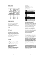
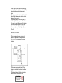
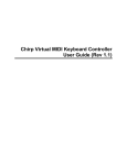
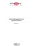
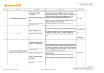
BIF
bi-phase interface
user manual
Table Of Contents
Installation
2
Controls
4
Reference point
6
User bits
7
Format
8
Operation
11
Clock generator
12
interstage
Phistersvej 31, 2900 Hellerup, Danmark
Telefon 3946 0000, fax 3946 0040
www.interstage.dk
- pro audio with a smile
14
-1-
INSTALLATION
4 BI-PHASE input
The bi-phase connector is a female
9-pin D-type socket:
1
2
3
4
5
6
7
8
9
anode opto-isolated input a
cathode opto-isolated input a
anode opto-isolated input b
cathode opto-isolated input b
Ground
TTL-input a
TTL-input b
Ground
5 volts output (100 mA)
1 POWER CONNECTION
Mains connection is provided by a standard
European mains cable (DIN 49464 F).
220-230 volts, 50-60 Hz, maximal consumption
is 4 watts.
2 MTC connector
This 5-pin DIN connector outputs Midi Time
Code (MTC). The MTC signal can be applied to
any MIDI interface. For reliable operation use
only shieldied Midi cables.
3 LTC output
The LTC output connector is a female RCA
connector The output impedance is < 1k ohms.
The LTC output level can be adjusted on the
front panel potentiometer with a small
screwdriver up to 3 Vpp.
For connecting to a balanced time code input,
just use a standard audio adapter cable.
-2-
Most bi-phase signals are standard TTL
outputs. In this case, use the TTL-inputs on pins
6 and 7. The TTL-inputs needs a good ground
connection from the bi-phase output to the biphase input (pin 5 & 8). Use only single
shielded cables. Use the shield as ground.
Don´t care about the polarity of the two signals,
because you can change it by software.
See "Input format" on page 8.
The two opto isolated inputs need a minimum
current of +10 mA. If your bi-phase outputs are
strong enough to drive these inputs (TTL
outputs are not), you should use the advantage
of opto-isolated inputs. Connect the bi-phase
outputs to the anodes and the output ground to
both cathodes. The bi-phase input ground can
be grounded too or also left be floating.
If you are using two mechanical switches as biphase clock, you can connect the two cathodes
to ground, and the 5 volts output serial through
the switches to the anodes.
-3-
Controls
7 Down key
In set mode (display is flashing) the down key
decreases the edited value. Holding the down
key over one second starts auto decrease.
Set mode is entered by pressing the up & down
keys simultaneously.
8 Mode key
In normal operation mode (display isn´t
flashing) the mode key passes through the
sequence of these three windows:
5 On key
Turns the BIF on and off.
Each time the BIF is powered up, it runs through
the display test ,displays the software version
and starts operation in the time code window.
8.8.8.8.8.8.8.8
Soft
1. 00
00. 00. 00. 00.
00. 00. 00. 00
The time code window displays the current
time of the bi-phase time code counter. Only
three decimal points (hours.minutes.seconds.)
are indicating the time code window.
The last decimal point (frames.) indicates
"locked".
0.0.0.0.0.0.0.0.
If it´s necessary to reset the BIF to default
parameters, then press and hold up & down
keys (6 & 7) when the power is turned on.
The BIF will display "reset".
rE SE t
The user bits window displays the current LTC
user bits. Eight decimal points are indicating the
user bit window.
Fo
24. 24
The format window displays the selected input
and output format.
6 Up key
In set mode (display is flashing) the up key
increases the edited value. Holding the up key
over one second starts auto-increase.
Set mode is entered by pressing the up & down
keys simultaneously.
-4-
In set mode (display is flashing) the mode key
passes through the set sequences.
9 LTC level
The SMPTE output level can be adjusted with a
small screwdriver up to 3 Vpp.
-5-
Reference point
Cue up your film transport to the reference
point.
Note: The exact edit point is the beginning of
the frame and not its centre. If you are using the
play back head of a mag machine as edit point,
the right end of the start mark must be in the
centre of the head, when the tape is running
from left to right.
Select the time code window with the mode
key.
00. 00. 00. 00
Enter set mode by pressing up & down keys
simultaneously.
xx. xx. xx. xx
All digits are flashing. You can set full hours
(nn.00.00.00) with up and down keys. Minutes,
seconds and frames will be set to zero.
Press the mode key.
xx. 00. 00. 00
Hours are flashing. You can set the hours with
up and down keys, without changing the
minutes, seconds and frames.
Seconds are flashing. You can set the seconds
with up and down keys.
Press the mode key.
00. 00. 00. xx
Frames are flashing. You can set the frames
with up and down keys.
Press the mode key.
FrEErun
In this window you can start the BIF by pressing
the up key as a free running, X-tal tuned time
code generator. The generator function is
stoped by the mode key.
Note: The generator starts from the current biphase position, but does not change or move
the reference point.
Press the mode key.
Now you are again in the normal operation
mode
and the new reference point it stored in the nonvolatile memory.
User bits
Press the mode key.
Select the user bits window with the mode
key.
00. xx. 00. 00
0.0.0.0.0.0.0.0.
Minutes are flashing. You can set the minutes
with up and down keys.
Enter set mode by pressing up & down keys
simultaneously.
x.x.x.x.x.x.x.x.
Press the mode key.
All digits are flashing. You can set the user bits
(0.0.0.0.0.0.0.n.) with up and down keys. User
bit group 2-8 will be set to zero.
00. 00. xx. 00
-6-
-7-
Press the mode key.
Press the mode key
0.0.0.0.0.0.0.x.
In. Fo. xx. Xx
First user bit group is flashing. You can set the
group with up and down keys, without changing
the other groups.
Input format is flashing.
You can set the input format with up and down
keys.
A bi-phase signal consists of two 90° shifted
square wave signals (a,b). If the two bi-phase
signals are reversed, the travel direction will
also be revesed. Therefore you can set the BIF
input format to bi-phase a,b (in.Fo.bp.ab) or biphase b,a (in.Fo.bp.ba).
Pulse & direction signals are decoded bi-phase
signals. One signal defines the travel direction
(forward / backwards), the other one is counting.
The travel direction could be reverse and also
the two signals could be exchanged. Therefore
the bif supports 4 different input formats called
Pd0, Pd1, Pd2, Pd3 for all four possible
combinations.
Step through all groups with the mode key until
you are back in the normal operation mode.
Format
Select the format window with the mode key.
Fo
24. 24
Enter set mode by pressing up & down keys
simultaneously.
Fo
xx. xx
Format is flashing. You can set the format with
up and down keys.
The first number is the transport format, the
second number is the generated output format.
If your mag machine is running at 24 frames per
second, generating a 48 Hz or multiple bi-phase
signal, and you want to generate 25 fps time
code, you must use [Fo 24.25].
Software version 1.00 supports 18.24, 18.25,
18.30, 24.24, 24.25, 24.30, 25.24, 25.25, 25.30,
3d.3d, 30.24, 30.25, 30.30.
-8-
Because there are only six posibilities (bp.ab,
bp.ba, Pd0, Pd1, Pd2, Pd2) the empirical
method is recommended.
Press the mode key
P.P.F.
xxx
Pulses per frame are flashing.
You can set the pulses per frame with up and
down keys.
Normally the bi-phase signals from a film
transport, running at 24 frames per secound,
are 48 Hz. This means two falling and two rising
edges per each frame (p.p.f. 4). But also 24,96
or 480 Hz signals are sometimes used. The BIF
can handle all rates from 1 to 256 pulses per
frame.
-9-
Start your first test with the default settings ppf
= 4 and input format bp.ab. If BIF is running in
reverse direction change the input format to
bp.ba.
If BIF runs with the half play speed set ppf = 2.
If BIF runs with the double play speed set ppf =
8. If BIF is toggling between two frames try input
formats pd0, pd1. pd2 or pd3.
If BIF is not counting at all, check your bi-phase
levels (See page 3).
Press the mode key.
S.out
oFF
Another method to cue up your DAW is the use
of the Midi Machine Control (MMC) „Locate“command, if your DAW software supports MMC
slave mode together with MTC slave mode.
If the slaved DAW supports the Midi Time Code
Full Frame messages set „S.out“ to „Full“
If the slaved DAW supports MMC slave mode
together with MTC slave mode, set „S.out“ to
„Loc“ (for example with Digidesign ProTools 4.2,
Roland VS-880, Fostex FD4).
You can set the Serial output mode with up and
down keys to:
„oFF“, „FuLL“, „Loc“, „q.F.“, „q.F.-2“.
If the slaved DAW only supports MTC slave
mode, try to cue up your DAW with the „S.out“settings „q.F.“ or „q.F.-2“ (the Creamware Triple
DAT software for example can be cued up with
the „q.F.-2“-setting).
Press the mode key again to return to the
normal operation mode.
If you do not use the MTC output, set „S.out“
mode to „oFF“.
Operation
Any DAW, which is able to chase to MTC, will
follow to your film transport at normal play
speed. If the film transport is moving slowly, fast
winding or moving reverse, MTC-slaved DAWs
will not follow to the film transport. For this
reason the BIF bi-phase interface supports
several tricky output modes to cue up your
slaved DAW frame-accurate also at non-play
speed.
The BIF is translating bi-phase signals from
90% to 110% of normal play speed into LTC
and MTC quarter frames. All other speeds from
0 up to 30 times play speed will be translated
into LTC-bursts and MTC full / locate / quarter
burst messages.
(See serial output mode)
An LTC burst is an LTC-loop of one frame. Most
LTC chase synchronizers will cue up to it.
Midi Time Code uses two types of messages,
described as quarter frame and full frame. The
quarter frame message is used for normal
running status at play speed and the full
message communicates a specific time for
cueing and locating.
Unfortunately most DAWs and sequencer
programs do not support the „full message“.
The decimal point of the frames (in the time
code window) is indicating locked time code
generation in play speed. In this "locked" mode
the BIF is interpolating even bad jittering biphase signals into jitterfree linear time code,
ideal for slaving digital audio systems.
- 10 -
- 11 -
Serial output mode is flashing.
The BIF´s non volatile flash memory (software
version 1.20 or higher/ hardware version bif.02)
stores all settings and also the power on/ off
status.
If the mains connection is temporarly interrupted
the unit holds the power on/ off status, entered
before with the on-key (5).
The reference point is stored at any time you
step through the reference point edit procedure.
If you want to switch off the unit without loosing
your actual transport-position you must store
your current position by stepping through the
reference point set procedure without changes
(Page 6).
Clock generator
This is an example how you can make a biphase clock generator with two light barriers
(CNY 37 or TCST 2000) and two 100 ohms
resistors.
The bi-phase aperture must be on the film
driving axle and must have at least 1 tooth per
frame.
The distance between both photo interrupters
must be the half of an apertures tooth.
interstage
- 12 -
Phistersvej 31, 2900 Hellerup, Danmark
Telefon 3946 0000, fax 3946 0040
www.interstage.dk
- pro audio with a smile