1
!
!
µEZ® Bootloader
User’s Manual
!
!
!
!
!
!
!
!
!
Copyright ©2014, Future Designs, Inc., All Rights Reserved
!!
Table of Contents
1.
2.
3.
4.
5.
6.
7.
8.
Introduction __________________________________________________________________________________________________________________5
Compatibility _________________________________________________________________________________________________________________5
Components __________________________________________________________________________________________________________________6
Base Bootloader _______________________________________________________________________________________________________________6
Application Bootloader ________________________________________________________________________________________________________6
Application’s Startup Tasks _____________________________________________________________________________________________________7
Questions ____________________________________________________________________________________________________________________7
Bootloader Quick Start _________________________________________________________________________________________________________8
Quick Start: Installing the Template Application _________________________________________________8
Configuring the Bootloader - Flip the Screen ____________________________________________________8
9. Bootloader Implementation _____________________________________________________________________________________________________9
Base Bootloader Configuration (BBL.INI) ________________________________________________________9
Application Bootloader Configuration (ABL.INI) _________________________________________________11
Example Project “Template App” _____________________________________________________________12
Template App Project Configuration (APP.INI and RESOURCE.INI) __________________________________12
CrossWorks 2.0 __________________________________________________________________________12
IAR ____________________________________________________________________________________13
Converting HEX file to BIN file (SplitLPC1788HexIntoBins.exe)_____________________________________16
Converting BIN files to IMG file (BIN2IMG.exe) __________________________________________________16
Copy and Test _____________________________________________________________________________17
10.Directory Structure on SDCard and USB Flash Drive ________________________________________________________________________________17
11.INI Customized Installs (INSTALL.INI) ____________________________________________________________________________________________18
Example INSTALL.INI file: ___________________________________________________________________18
Structure of INSTALL.INI file _________________________________________________________________19
INSTALL section __________________________________________________________________________19
File sections_____________________________________________________________________________19
Types __________________________________________________________________________________19
12.uEZ® Resource Packager (uEZRP.exe) ____________________________________________________________________________________________20
Appendix A: Test Case Scenarios______________________________________________________________________________________________21
TC1 __________________________________________________________________________Bootloader Test
21
TC2 ____________________________________________________________________Loading an application
21
TC3 ___________________________________________________________________Upgrade the application
22
TC4 _________________________________________________________Interrupt power at start of upgrade
22
TC5_________________________________Interrupt Power when new application is copied to internal flash
23
TC6 ______________________________________________________________Upgrading with Invalid Images
24
TC7 ____________________________________________________________________No Images on USB drive
24
TC8 ___________________________________________________________________Corrupted internal flash
24
TC9 _______________________________________________________________________No ABL on USB drive
24
TC10______________________________________________________Unattended Mode and Rename Feature
24
TC11 __________________________________________________________________Product Name matching
!2
25
TC12 __________________________________________________________________________Rotated Screen
25
TC13 Portrait Mode _________________________________________________________________________25
TC14 USB PortB ____________________________________________________________________________25
TC15 Off Board SDCard _____________________________________________________________________25
TC16 ___________________________________________________________Two Products on One Flash Drive
25
TC17 _______________________________________________Install from Flash Drive with Multiple Products
25
!
Appendix B: Image Header Format _________________________________________________________________________________________________26
!3
Information in this document is provided solely to enable the use of Future Designs products. FDI assumes no liability whatsoever, including
infringement of any patent or copyright. FDI reserves the right to make changes to these specifications at any time, without notice. No part of this
document may be reproduced or transmitted in any form or by any means, electronic or mechanical, for any purpose, without the express written
permission of Future Designs, Inc. 996 A Cleaner Way SW, Huntsville, AL 35805.
!
For more information on FDI or our products please visit www.teamfdi.com.
NOTE: The inclusion of vendor software products in this kit does not imply an endorsement of the product by Future Designs, Inc.
© 2014 Future Designs, Inc. All rights reserved.
!
uEZ® is a registered trademark of Future Designs, Inc.
Microsoft, MS-DOS, Windows, Windows XP, Microsoft Word are registered trademarks of Microsoft Corporation.
Other brand names are trademarks or registered trademarks of their respective owners.
!
FDI PN:
Revision: 1.04, 1/06/2014
Printed in the United States of America
!
!4
!
1. Introduction
The following document gives an overview of the uEZ® Bootloader design for uEZ based projects. The
Bootloader allows maximum customer flexibility by permitting the Application Specific Firmware to be
updated remotely in the field or by the customer without the use of any special programming tools or
devices. All that is needed is a common USB Flash Drive or SD Card with the necessary files from FDI.
!
The Bootloader consists of two primary components that are structured to provide the maximum flexibility
and reliability in your product. The Base Bootloader (BBL) provides the base set of functions that should
never change and can be considered static since it is programmed into the boot sector of the base processor.
The Application Bootloader (ABL) contains the higher level intelligence needed to program both internal and
external Flash memory and can be updated dynamically by FDI since it is loaded from local memory such as
the SD Card or USB Flash drive when it is required. Care has been taken to ensure the unit keeps operating
even if there are interruptions during the “boot load” process.
!
The Base Bootloader (BBL) occupies 64KB of space in the CPU’s internal Flash. The Application Bootloader
(ABL) is larger, but since it is loaded dynamically from external memory like a USB Flash Drive or a micro SD
Card, the size is not important.
!
The Bootloader is part of FDI’s uEZ+ product offering and as such is a licensed component that must be
purchased from FDI and registered before use. Please consult the uEZ+ Software End User License
Agreement for complete details.
!
2. Compatibility
The uEZ Bootloader currently supports the following processors:
• NXP LPC4088
• NXP LPC1788
• NXP LPC2478
• NXP LPC1756
• NXP LPC1768
!
Additional processors are constantly being added so please consult our website or contact FDI for updates.
!
The following compilers are currently supported:
• IAR Systems EWARM (ARM7 and Cortex-M3)
• Rowley Crossworks
!
Additional compilers are constantly being added so please consult our website or contact FDI for updates.
!
The following Off-The-Shelf hardware and boards from FDI are currently supported:
• uEZ GUI 4.3 (UEZGUI-1788-43WQS, UEZGUI-1788-43WQS-BA, UEZGUI-4088-43WQN,
UEZGUI-4088-43WQN-BA, UEZGUI-4088-43WQN-NXP)
• uEZ GUI 5.6 (UEZGUI-1788-56VI, UEZGUI-1788-56VI-BA)
• uEZ GUI 7.0 (UEZGUI-1788-70WVE, UEZGUI-1788-70WVE-BA, UEZGUI-1788-70WVT,
UEZGUI-1788-70WVT-BA, UEZGUI-1788-70WVM, UEZGUI-1788-70WVM-BA)
!
!5
Additional hardware support is constantly being added so please consult our website or contact FDI for
updates.
!
uEZPlus Bootloader v1.04 and later is not compatible with the previous version, both the ABL and BBL must
match versions. Upgrading to this version from v1.03 will require a new product name if existing products
are in the field.
!
3. Components
The project uses the following hardware components:
• uEZ Implementation
o USB Flash drive slot or SDCard slot
o CPU Flash (usually 512KB total) containing,
▪ Bootloader (64K)
▪ Current Application
External
NOR Flash (optional, usually up to 16 MB):
o
Graphics/Data
Partition
▪
SDCard
(2
GB
or
larger):
o
▪ Upgrade Application File
▪ Upgrade Graphics/Data File (~8.0 MB)
▪ Additional SDCard Files
!
4. Base Bootloader
The Base Bootloader (BBL) is a core set of code that never changes and is programmed into the boot sector
of the processor. The BBL is a simple program that runs whenever the processor boots and checks to see if a
USB Flash drive or SDCard is inserted with installation files.
• If a USB Flash drive or SDCard is found with installation files, the Application Bootloader (ABL) is loaded
from the drive and run from SDRAM. • If no USB Flash drive or SDCard with installation files is found, the Application in the processor’s internal
Flash is validated and then run. If the Application is invalid, then an error is presented (see note
below). • The BBL’s only job is to run either the ABL or the Application. The BBL does no actual programming.
• The BBL will only load an ABL that has a matching product name to ensure compatibility.
• Failure to properly load the Application will result in an error message on the unit.
!
5. Application Bootloader
The Application Bootloader (ABL) provides the intelligence required to handle programming of both internal
processor Flash and external NOR Flash.
• The ABL is loaded from the USB flash drive or SDCard and run by the BBL.
• The ABL looks at the versions for the processor’s internal Flash and external NOR Flash (Graphics/Data),
shows the versions on the screen and then programs the new images if the user agrees with the update
request (see test cases).
• The ABL also will not install any files that do not have a matching product name.
• Failure to write to any of the devices will produce an error and present an error message on the LCD. (NOTE: Any errors at this level will take the unit out of service, but retrying to upgrade is allowed).
Failures are optionally logged to the SDCard.
!
!6
6. Application’s Startup Tasks
When programming is complete and valid, the Application loads. • The Application will start by checking the external NOR Flash for proper image(s) using source code tools
provided and also check any other files that may be present on the SD Card (if used).
• It is up to the Application to update any SD Card files from the USB Flash drive (which is still plugged in
when the ABL ends).
• It is also up to the Application to decide how to handle any errors that occur at this level, since the ABL
is not aware of the unique error handling requirements for each customer’s application.
!
7. Questions
!
What happens if upgrading an Application image is incomplete?
Incomplete partitions will not match their 32-bit checksum. Any failed section will cause the unit to stop
and ask for an upgrade. This action will continue until the upgrade is successful.
!
What happens if a partition becomes corrupt?
The failure will be logged to the SDCard (if enabled and supported). The bootloader will prompt for upgrade
files on the USB Flash Drive or SDCard. The user can attempt to fix the problem by inserting a drive with a
correct image and reboot. The bootloader will then copy over the files and restore the unit.
!
What keeps the Bootloader from getting corrupted?
The Bootloader is programmed once (either during production or by the customer if desired) and is
protected from being over written. This section of the application flash cannot be erased except by use of
external hardware tools, such as a JTAG programmer, that are not normally available to an end user.
!
What ensures a set of files for another product cannot be installed on this product?
The Bootloader system requires that all files have the same product name. Tools have been provided to
configure the base bootloader with a specific product name. This short name (up to 15 case sensitive
characters) should represent what the hardware is and if it is compatible with the names given in the
product. The same product name must be found in the ABL and any image files installed. Otherwise, the
complete install will be rejected.
!
!
!7
8. Bootloader Quick Start
The Bootloader includes a set of pre-built example files, using the “Template App” in the \Images directory.
These examples are all that a typical user should need to install, configure, and run their application.
Quick Start: Installing the Template Application
Follow these steps to install an example:
1) Go to the appropriate directory for your hardware platform. For example, if you are working on
uEZGUI-1788-70WVT and want to use the microSD based bootloader, go to \Images
\uEZGUI-1788-70WVT\SDCard
2) In this directory, there should be a subdirectory called “config” which contains all the .INI files for
configuring your bootloader. In the directory “objs” is where all the binaries for the bootloader are
placed. The directory “SDCard” or “USBFlash” is where the files to be copied to the removable
media are placed.
3) Run the file “build_media.bat”. It will run and setup all the files for your removable media in
“SDCard” or “USBFlash”.
4) Go into the media directory. Copy all of these files to your removable media (it should be the
directories “BOOT”, “Bootloader”, and file “INSTALL.INI”).
5) Plug the media into your target hardware.
6) On the PC and with the target connected to a JTAG adapter cable, go into the directory “Bootloader”
and double click the file “Install JLink.jlink”. If Windows asks for a program to use with the .jlink
file, point it to your current version of the Segger JLink Commander program (e.g., “Program Files
\Segger\JLink vX.XX\JLink.exe”). This will install the bootloader to your target hardware.
7) If the above steps work correctly, the target will immediately reset, quickly show “uEZ Base
Bootloader v1.01”, load the Application Bootloader, report “uEZ Generic ABL v1.01” and ask “Do you
want to install these files? (Yes/No)”.
8) Click Yes and wait for the install to complete.
9) When complete, remove the media, and press OK.
10) The unit will reset, show the bootloader screen again, boot the application, ask for touch screen
calibration (if not already done), and then boot to a screen showing the uEZ logo and “Hello, World”
text.
11) This completes the “Template Application” install. Refer to the following sections for more in depth
options and steps for using with your application.
Configuring the Bootloader - Flip the Screen
If the bootloader text and UI displays upside-down in your product mounting configuration, you can easily
configure the bootloader for 180 degree rotation by following these steps:
1) Again, go the appropriate directory for your hardware platform.
2) Go into the subdirectory config and edit the BBL.INI with a text editor.
3) Change “flipx = false” to “flipx = true” and “flipy = false” to “flipy = true”.
4) Save the file BBL.INI and exit the text editor.
5) Go back up one directory and double click “build_media.bat”.
6) Still on the PC and with the target connected with a JTAG adapter cable, go to the directory
Bootloader (under “SDCard” or “USBFlash”) and double click the “Install JLink.jlink” file. This will
install a modified base bootloader that has been configured for rotated screen.
7) The unit will now reboot and the screen will be rotated. No other changes are needed. NOTE: The
Template Application does not rotate as the bootloader system does not pass this information to the
application.
8) Using the same technique, there are other features such as contact information, unattended mode,
screen blanking, etc. that are documented in the sections below that can be configured by the user.
!8
9. Bootloader Implementation
The Bootloader files are delivered in the following format for each platform and compiler supported:
o BBL project directory (binaries and source)
o ABL project directory (binaries and source)
o Example project directory (binaries and source)
Base Bootloader Configuration (BBL.INI)
The Base Bootloader source code is provided in the directory \Source\App\BBL. Binary files for the BBL are
provided already built and ready for User Configuration in the \Build\<Platform>\<Compiler>\BBL\<Version>
directories. These BBL files do not have a product name associated with them and must be configured using
the following configuration file and command before they can be used:
!
File config\BBL.INI (replace the <bracketed> items with the appropriate items for your project):
[files]
input = \Build\<Platform>\<Compiler>\BBL\Release <Version>\BBL.BIN
output = BBL.BIN
!
!
[config]
contact = "YourCompany (www.yourcompany.com)"
hidden = false
unattended = false
flipx = false
flipy = false
product = YourProduct
Configure with the command (generating the output specified above):
\bin\ UEZBootloaderConfig config\BBL.INI
!
An example of the BBL being configured is provided in the Template App using the file \config\BBL.INI.
!
Once the BBL.BIN file is created, on a computer with Segger J-Link Commander installed on it, double click
the file “Program BBL.jlink” to install the BBL.
!
BBL.INI Settings for [config]
Field
Value Type
Description
contact
String up to
Short message to show on the screen if the base bootloader fails to load. This
80 characters can be your website, phone number or contact information but please realize
that it will be permanent for the life of your product in the field. Default is
FDI contact information.
flipx
true|false
If true, the display is flipped along the horizontal direction. Usually used with
flipy to rotate the screen 180 degrees. This setting is passed on to the ABL.
flipy
true|false
If true, the display is flipped along the vertical direction. Usually used with
flipx to rotate the screen 180 degrees. This setting is passed on to the ABL.
hidden
true|false
If true, the base bootloader screen will not be shown unless there is an error
or the ABL is to be loaded.
!9
unattende
d
true|false
If true, tells the base bootloader never to ask for input from the user unless a
major error occurs. Currently not used. See unattended setting for ABL.INI
instead.
portrait
CC | CW
CC represents a clock-wise physical rotation of the unit (+90 degs)
CW represents a counter clock-wise physical rotation of the unit (-90 degs)
This option should not be added if not needed, the default value is neither.
usbport
A|B
This option allows a switch between the off board USB port “A” on the
expansion connector or the on-board USB OTG connector. The default value is
“A”.
sdcard
ON | OFF
This option allows for switching to an off board SDCard socket, see tables
below for pin out. The default is to use the on board.
product
Up to 15
chars
Unique product name for this installation. All installation files must refer to
this same product name or installs will fail. Default is standard ID for this
platform.
!
NOTE: All of the above settings are factory settings. Once the base bootloader is installed in your
product, these settings CANNOT be changed again without using hardware programming (JTAG). Please
make sure these settings are correct before continuing.
!
uEZGUI-1788-43WQS, uEZGUI-1788-43WQR, uEZGUI-1788-70WVT, and uEZGUI-1788-56VI SDCard settings
!
On Board
GPIO
Expansion Connection
Port
SSP0
NA
SCK
P2.22
NA
MISO
P2.26
NA
MOSI
P2.27
NA
CS
P2.21
NA
Off Board
GPIO
Expansion Connection
Port
MCI0
NA
DAT0
P1.6
J5.8
DAT1
P1.7
J5.7
DAT2
P1.11
J5.6
DAT3
P1.12
J5.5
CLK
P0.19
J4.4
CMD
P0.20
J4.3
!
!
!
uEZGUI-4088-43WQN, and uEZGUI-1788-70WVM SDCard settings
!
!10
On Board
GPIO
Expansion Connection
Port
MCI0
NA
DAT0
P1.6
NA
DAT1
P1.7
NA
DAT2
P1.11
NA
DAT3
P1.12
NA
CLK
P0.19
NA
CMD
P0.20
NA
Off Board
GPIO
Expansion Connection
Port
SSP1
NA
SCK
P0.7
J4.18
MISO
P0.8
J4.17
MOSI
P0.9
J4.16
CS
P0.6
J4.19
!
!
!
NOTE: these pins cannot be change from the values listed above.
Application Bootloader Configuration (ABL.INI)
The Application Bootloader source code is provided in the directory \Source\App\ABL. Binary files for the
ABL are provided already built in the \Build\<Platform>\<Compiler>\BBL\<Version> directories. An example
of the ABL being User Configured is in the Template App. The Application Bootloader (ABL.IMG) goes on the
USB flash drive or SDCard in the directory \BOOT along with the other install files. The ABL uses the
INSTALL.INI file in the root of the SDCard or USBFlash to control installation.
!
Before an ABL.BIN can be used, it must be given an .IMG header and configured with the product name. A
configuration file (e.g., \config\ABL.INI) must be generated:
!
\config\ABL.INI File:
[header]
product = YourProduct
location = 0x10001000
!
Use the following command to configure the ABL.BIN into an ABL.IMG and place in the SDCard or USBFlash
drive’s BOOT directory:
\bin\Bin2Img objs\ABL.BIN config\ABL.INI \BOOT\ABL.IMG
!11
!
The product name must match the name in the base bootloader or the ABL will be rejected.
!
The configuration is done using the BIN2IMG tool as explained in the Example Project. See the following
section “INI Configured Installs” for more details.
!
ABL.INI Settings for [header]
Field
Value
Type
Description
produc
t
Up to 15
chars
Unique product name for this installation. All installation files must refer to this
same product name or installs will fail. Must match product name in BBL.INI.
locatio
n
Hex
address
32-bit address to load the ABL at. Depends on the target. Use the same value as the
one in the example application (e.g., LPC1788 uses 0x10001000)
!
Example Project “Template App”
The example project brings up a demo application that shows the install worked. The example is a full
featured example showing configuration and installation of the BBL and ABL for either SDCard or USBFlash
versions for all supported compiler types. Each template app’s build files can be found in the “\Bootloader
\Build\<Platform>\<Compiler>\Template App” directory. Additionally, scripts have been provided to collect
and configure the files in one command. Choose if you are doing a SDCard or USBFlash build and go to
“Make SDCard” or “Make USBFlash”. Double click on “make_release.bat” to create a set of files under
“SDCard” or “USBFlash”. The subdirectory “Bootloader” contains a configured version of the base
bootloader and the rest of the files (INSTALL.INI, BOOT/ABL.BIN, BOOT/APP.BIN, etc.) should be copied to
your SD Card or USB Flash drive for installation. The script “make_release.bat” uses the files in \config and
the script \bin\MakeTempalteApp.bat to create the final files for all the template applications. Details for
setting up the application and configuring these files are provided in the following sections.
!
Template App Project Configuration (APP.INI and RESOURCE.INI)
The Template App project places the application at 64K past the start of memory to make room for the BBL.
For example, on the LPC1788, the application must start at 0x00010100. The bootloader takes up the first
64KB at 0x00000000 – 0x0000FFFF and a 256 byte header must be at 0x00001000. Details are provided below
on how to configure each compiler for moving the base address.
!
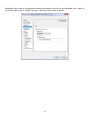
!In an application built for Crossworks, in the project explore, right click on Project ‘Your Project’ and select
CrossWorks 2.0
“View Memory Map (as text)”. A xml file will open in the main editor. Find the line that says,
<MemorySegment size="0x80000" access="ReadOnly" start="0x00000000" name="FLASH"/>
And change it to make room for the bootloader and the 256-byte application header. Adjust the size as
well:
<MemorySegment size="0x6FF00" access="ReadOnly" start="0x00010100" name="FLASH"/>
!
Compile the code again. From this point forward, you can still debug your code, but it will only run if ran
with a debugger or the bootloader.
!
!12
Additionally, the output of the application should also generate a hex file for the Bootloader tools. Make
sure the project property Linker Options -> Additional Output Format is set to “hex”.
!
!
!
!
!
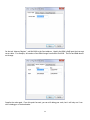
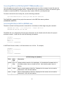
IAR
In an application built for IAR, go to Project Options, select “Linker” and select tab “Config”. Under “Linker
configuration file”, select Edit… The “Linker configuration file editor” will appear. Change the .intvec from
0x00000000 to 0x00010100.
!
!13
!
!
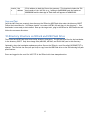
On the tab “Memory Regions”, add 0x10100 to the Start address. Usually the ROM is 0x80 past the interrupt
vector table. For example, this makes a Start ROM change from 0x80 to 0x10180. The End and RAM should
not change.
!
!
!
Compile the code again. From this point forward, you can still debug your code, but it will only run if ran
with a debugger or the bootloader.
!
!14
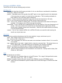
Additionally, the output of the application should also generate a hex file for the Bootloader tools. Again, in
the Project Options, go to “Output Converter” and setup a hex output as follows:
!
!
!
!15
Converting HEX file to BIN file (SplitLPC1788HexIntoBins.exe)
Once the application is built in the correct memory location and a hex file is created, the hex file must be
converted into a specially packaged format. The HEX file is first converted into a binary file and then given
a header to create an IMG file. If your project only creates a .BIN file, just skip this step.
!
To convert the hex file into a binary file, use the following command:
!
!
SplitLPC1788HexIntoBins YourProject.HEX APP.BIN FLASH.BIN
The FLASH.BIN is created if the project has resources in the NOR Flash memory address
(0x80000000-0x80FFFFF).
Converting BIN files to IMG file (BIN2IMG.exe)
The above created .bin file(s) must be converted into a checksum verified image using the command:
!
!
BIN2IMG <bin file> <.ini config file>
BIN2IMG APP.BIN APP.INI APP.IMG
<output IMG file>
The APP.INI file is a configuration file that puts information into the header and tells where the project
should be located. Create the file with the following information:
!
[header]
product = YourProject
major = 1
minor = 0
location = 0x00010000
!
If NOR Flash files are needed, it will also need its own .INI file. For example,
!
[header]
product = YourProject
major = 1
minor = 0
location = 0x80000000
!
APP.INI Settings for [header]
Field
Value
Type
Description
produc Up to 15 Unique product name for this installation. All installation files must refer to
t
chars
this same product name or installs will fail. Must match product name in
BBL.INI.
major
integer
Major version number of this file. Displayed on the screen, but not used to
determine if a file will be installed.
minor
Integer
Minor version number of this file. Displayed on the screen, but not used to
determine if a file will be installed.
!16
locatio Hex
n
address
!
32-bit address to load the file on the processor. This location includes the 256
byte header of the .IMG file (e.g., loading to 0x80000000 puts the header at
0x80000000 and the data App or Flash data will appear at 0x80000100.
!
Copy and Test
Once the IMG file(s) are created, place them on the SDCard or USB Flash drive under the directory \BOOT.
Follow the instructions for “INI Custom Installs” to create a INSTALL.INI and place in the directory \. Your
bootloader is now ready to be installed. Boot up the target unit, plug in the SDCard or USB Flash drive and
follow the on screen directions.
!
10.Directory Structure on SDCard and USB Flash Drive
The SDCard and USB Flash drive have similar directory structures. The SDCard have files for the bootloader
in the directory \BOOT. Only three image files (ABL.IMG, APP.IMG, and FLASH.IMG) are in this directory.
!
Optionally, when the bootloader updates any other files on the SDCard, a root file called \UPGRADE.TXT is
opened. This file lists the files (one per line) to copy from the USB Flash drive to the SDCard using full path
specifications.
!
Errors are logged to the root file \LOG.TXT of the SDCard with time stamped entries.
!
!17
11.INI Customized Installs (INSTALL.INI)
The uEZ Application Bootloader (ABL) uses the file “INSTALL.INI” on the flash drive to configure the way files
are installed on the system and the various locations for these files to be installed.
Example INSTALL.INI file:
!
[INSTALL]
description=”Template Application”
product=Template App
helpline=”Contact YourCompany at www.yourcompany.com”
file1=App
file2=Resources
clear=false
corrupt=false
rename=false
!
[App]
name=Template Application
file=0:BOOT/APP.IMG
image=true
type=flash
device=IAP
address=0x00010000
!
[Resources]
name=Template App Resources
file=0:BOOT/RESOURCE.IMG
image=true
type=flash
device=Flash0
address=0x80000000
!
!18
Structure of INSTALL.INI file
The INSTALL.INI file has the following major sections.
INSTALL section
The INSTALL section describes the file group and what it is for as what files are considered for installation.
description – Name of this install
product – Embedded name of the product that MUST match in the image files and in the bootloader.
If this name does not match, the install will not take place. This is a safety mechanism to
keep installs in sync with their proper installation.
helpline – Contact information presented on the screen should the install fail or fail badly.
fileX – a list of file sections that follow the INSTALL section starting with file1.
clear – If set to true, instead of installing files, it will ask to clear each section where a file may be
installed. Still requires a list of files that might be installed.
unattended -- If true, the ABL will be loaded and told to run the install as if the user the agrees to all
installs. This can be useful if the install files are downloaded by the application and the
install needs to happen without user intervention. Used with the rename feature (see below)
to avoid repeated installs.
rename – If set to true, renames INSTALL.INI to INSTALL.FIN after a successful install ensuring the
install can only be done once.
File sections
The next sections provide information on the file to be installed, its type, and where to put it.
name – User friendly name of file to show on display
file – location of file on flash drive
image – true if the image is an .IMG file that needs to be checksum checked or false if it is a raw file
to be copied.
type – general type of file install. Usually flash for internal or external flash. The internal area on a
CPU is usually flash. As the ABL feature set is expanded, new features are added.
address – If required for the given type, an address can be provided in hexadecimal
device – Tells which internal device driver to target (uEZ device driver name).
crc32 – optional field to manually set the checksum for this install file. Usually used for binary files
without an .IMG header.
Types
Types of flash files are as follows:
flash – Flash device is a standard flash unit in the uEZ system. The ‘target’ field specifies the exact
flash device name. (e.g., “IAP”, or “Flash”)
EEPROM – upgrades can also overwrite sections of an EEPROM using the uEZ EEPROM system.
Other – other types will be added for specific models such as ones that target I2C devices with flash
memory.
!
!19
12.uEZ® Resource Packager (uEZRP.exe)
User Configurable .IMG files can be made up of several smaller files can be created using the uEZ® Resource
Packager. Resources are files of any type that may or may not need to be converted to other formats. The
uEZ Resource Packager uses a configuration file to automate the process of converting images and then
combing them into a single .IMG file. Once the image is programmed into the NOR Flash, the uEZ Resource
system allows direct access to the packed resources without the need to change the application code.
!
!
!
!20
Appendix A: Test Case Scenarios
The follow section details the test/use cases for a configuration where an application, its graphics, and a set
of SDCard files are being installed from a USB Flash drive. This demonstrates only one configuration. For
bootloaders where an SDCard is the install medium, the following sections will say “SDCard” instead of “USB
Flash”.
TC1 Bootloader Test
1. Power on a unit with only the bootloader software installed. There should be no application images
in internal flash or on the SDCard. (Use Test Files “Clear” if necessary).
2. Verify that the screen reports, “Insert USB drive with application files. ”
3. Insert USB drive with application files. (Test Files “Primary”)
4. Since a USB flash drive is plugged in, the USB flash drive files will be scanned and the following is
reported:
“USB Flash Drive Detected. Scanning for new firmware…”
“Application x.xx found (current version NONE)”
“Graphics/Data x.xx found (current version NONE)”
“SDCard File <filename> x.xx found (current version NONE)” where <filename> is 0 or more files
on the USB Flash drive.
5. Unit should report progress (percentage or number of bytes). Each progress should report one of the
following:
“Installing Application x.xx … ### bytes”
“Installing Graphics/Data x.xx … ### bytes”
“Copying SDCard File <filename> x.xx … ### bytes” where <filename> is 0 or more files on the USB
Flash drive.
where x.xx is the version of that image.
6. Wait for message, “Installation successful. Remove USB drive. Press OK to reboot.”
7. Remove USB flash drive.
8. Press OK and the unit will reboot.
9. The application should now boot.
TC2 Loading an application
1. Power up a unit that has had its firmware already installed and does NOT have a USB flash drive
inserted.
2. The unit should report on the screen, “Verifying Application …”
3. When complete, and no problems are found, it should report, “Firmware valid.”
4. The application should now boot properly.
5. NOTE: It is up to the Application to check the validity of the NOR flash image and any SDCard Files.
!
!21
TC3 Upgrade the application
1. Insert a USB flash drive (with ABL and application files) into a unit that already has had its firmware
installed.
2. Power up the unit.
3. Since a USB flash drive is plugged in at power up, the USB flash drive files will be scanned and the
following is reported:
“USB Flash Drive Detected. Scanning for new firmware…”
“Application x.xx found (current version x.xx)”
“Graphics/Data x.xx found (current version x.xx)”
“SDCard File <filename> x.xx found (current version x.xx)” where <filename> is 0 or more files on
the USB Flash drive.
Verify that the unit asks, “Do you want to install these files?” with a prompt for YES or NO.
4. Press NO.
5. Verify the unit says, “Please remove the USB flash drive” with a prompt for OK.
6. Remove the USB flash drive and press OK.
7. Notice the application reboots without upgrading the unit (as long as the USB Flash Drive is not
plugged in, otherwise an upgrade will be attempted again).
8. Put the USB flash drive in the system and power cycle the unit.
9. The unit should show the versions again and offer the same question again with a YES / NO prompt.
10. This time, press YES.
11. The unit will now install the new firmware (same information as TC1).
12. When complete, when the prompt “Please remove the USB flash drive” appears, remove the USB
drive, and press OK to reboot the unit.
13. The application should now boot properly.
TC4 Interrupt power at start of upgrade
1. Insert a USB flash drive (with new application files) into a unit that already has had its firmware
installed.
2. Power up the unit.
3. Since a USB flash drive is plugged in, the USB flash drive files will be scanned and the following is
reported:
“USB Flash Drive Detected. Scanning for new firmware…”
“Application x.xx found (current version x.xx)”
“Graphics/Data x.xx found (current version x.xx)”
“SDCard File <filename> x.xx found (current version x.xx)” where <filename> is 0 or more files on
the USB Flash drive.
4. Verify that the unit asks, “Do you want to install these files?” with a prompt for YES or NO.
5. Power off the unit.
6. Remove the USB flash drive.
7. Power back on the unit.
8. The software should continue with no change (same steps as TC2).
9. Verify that the old application boots properly.
!22
TC5 Interrupt Power when new application is copied to internal flash
1. Insert a USB flash drive (with new application files that differ from the current files on the unit’s
SDCard) into a unit that already has had its firmware installed.
2. Power up the unit.
3. Since a USB flash drive is plugged in, the USB flash drive files will be scanned and the following is
reported:
“USB Flash Drive Detected. Scanning for new firmware…”
“Application x.xx found (current version x.xx)”
“Graphics/Data x.xx found (current version x.xx)”
“SDCard File <filename> x.xx found (current version x.xx)” where <filename> is 0 or more files on
the USB Flash drive.
4. Verify that the unit asks, “Do you want to install these files?” with a prompt for YES or NO. Click
YES.
5. The unit will now start to copy over the new firmware (same information as TC1).
6. When the application starts upgrading with message “Installing Application …” (but before it
finishes), turn off the power. This should corrupt the image in internal flash.
7. Remove the USB flash drive.
8. Power back on the unit.
9. Verify that an error is reported for the image corrupted above.
10. Repeat when doing updates in the “Copying Graphics/Data…” step and the “SDCard File” steps. The
Application, however, may report that one or more of its SDCard files need to be updated.
!
!23
TC6 Upgrading with Invalid Images
1. This test will be repeated 6 times. Read through the test closely.
2. Setup a USB flash drive with the normal/valid files for an upgrade.
3. On the first three times through this test, modify one of the three USB flash files to be an invalid
file. If doing the last three tests, just delete the file.
4. Insert the USB flash drive into a unit that already has had its firmware loaded.
5. Power up the unit.
6. Since a USB flash drive is plugged in, the USB flash drive files will be scanned and one the following
lines may be reported (as files are found and checked for validity):
“USB Flash Drive Detected. Scanning for new firmware…”
“Application file invalid!” or “Application file not found!” or
“Graphics/Data file invalid!” or “Graphics/Data file not found!” or
NOTE: It is up to the Application to check the validity of any other files on the SDCard.
7. As soon as one of the above messages appears, the message “Cannot copy these images into unit
unless all are valid. Remove USB flash drive and press OK to reboot” is shown.
8. Remove the USB flash drive.
9. Press OK.
10. Notice the unit reboots and runs correctly without copying or installing files.
11. As noted in the first step, repeat this step for all 6 cases.
TC7 No Images on USB drive
1. Power on a unit with only the bootloader software installed. There should be no application images
in internal flash.
2. Verify that the screen reports, “Insert USB drive with application files.”
3. Nothing should happen until a USB drive is inserted.
TC8 Corrupted internal flash
!
1. On a fully valid and running board, run program “CorruptInternalFlash” and have it corrupt the
application and graphics/data.
2. Without a USB flash drive loaded, power on the unit.
3. The unit should report on the screen, “Verifying app… Does not exist. Insert drive w/ app files”. If
the image is found to be invalid, it is reported as “Invalid” and then the system is halted with the
message “Application image is invalid! Report problem to {contact information}”. An error will be
logged internally to the SDCard that there is a failure here.
NOTE: It is up to the Application to check the validity of the NOR flash and any other SDCard Files.
TC9 No ABL on USB drive
!
1. Power on a unit with only the bootloader software installed. There should be no application images
in internal flash.
2. Verify that the screen reports, “Insert USB drive with application files.”
3. Insert a USB drive that does not have an ABL file.
4. The message “ABL not found” should appear and then go back to step 2.
TC10 Unattended Mode and Rename Feature
1. Power a unit fully programmed with a standard version of software.
2. With a drive setup for “unattended” mode enable and “rename” mode enabled (both fields are set
to true in the INSTALL.INI file, install a second program starting with double clicking on the file
“Install BBL.jlink” and then using the files on the drive.
3. Verify that the program installs immediately when the drive is plugged in and no questions are asked.
4. Verify that the unit boots properly by itself.
5. Also verify that it boots the second program without going back to the bootloader.
6. Unplug the drive and take back to the PC.
7. Verify the file INSTALL.INI has been renamed to INSTALL.FIN.
!24
!
TC11 Product Name matching
1.
2.
3.
4.
5.
!
Power a unit fully programmed with a standard version of (primary) software.
Plug in a flash drive with the second software package.
Verify the message “Could not install Product uEZG… install files not found” appears
Now copy over an install with an error in product app and load this one.
The ABL will load this time, but when it searches the files, it will report “Incompatible file!” for the
Application.
6. Now copy over an install with an error in the graphics and try to install this one.
7. Again, the ABL will load, but it too will report “Incompatible file!” when it reaches the graphics file.
TC12 Rotated Screen
!
1. Power up a unit and run the bootloader (BBL) installer in the Flip XY package. (Test Files “Primary
FlipXY”)
2. Verify the base bootloader loads with the display rotated 180 degrees.
3. Plug in a flash drive with the Flip XY files.
4. Verify you can install the application with the screen turned this way.
5. Note, however, that the application orientation is the same as done in the other tests.
TC13 Portrait Mode
!
1. Run the test file in PortraitXX, application not affected.
TC14 USB PortB
!
1. Run the test file in USB PortB
TC15 Off Board SDCard
!
1. Run the test file on the off board microSD card using EXP-DK on 43WQR/70WVT.
2. On the 70WVM/43WQN use the microSD card on….
TC16 Two Products on One Flash Drive
!
1.
2.
3.
4.
5.
Put on a flash drive a build with two products (Test Files “Primary and Secondary”).
Now program the unit with the v1.05 Bootloader BBL from “Primary”.
Insert the flash drive and notice that it installs the product “Primary”.
Now program the unit with the v1.05 Bootloader BBL from “Secondary”
Insert the flash drive and notice that it installs the product “Secondary”
TC17 Install from Flash Drive with Multiple Products
!
1.
2.
3.
4.
5.
Put in a flash drive a build with multiple products (Test Files “Multiple”).
Now program the unit with the v1.05 Bootloader BBL from “Primary”.
Insert the flash drive and notice that it installs the product “Primary”.
Now program the unit with the v1.05 Bootloader BBL from “Secondary”
Insert the flash drive and notice that it installs the product “Secondary”
!25
Appendix B: Image Header Format
The format of each image/file contains the following bytes. All values are given in little endian format.
This header is stored with the image data. The data then directly follows this header.
!
Item
Size
Description
Header
4
Common header for all these files. Must be Hex string 0x48 0x49 0x6D
0x67 for “HImg”
Header size
2
Size in bytes (16-bit value).
Length
4
Number of bytes of this image past this header.
Product ID
32
Null terminated product ID. Must match expected product name
programmed in bootloader.
Reserved
32
Padding of 0’s. Reserved for future use. Must be 0’s.
Version info
4
Must exactly match the other files on the USB drive. First 2 bytes are
major version number. Second 2 bytes are minor version number.
Image location
4
32-bit address in memory. If a standard file on the SDCard, this
location is 0.
CRC
4
CRC of the following data of the above size
Reserved
170
Padding of 0’s to make the header the same size and to reserve possible
future information.
!
!
!26