1
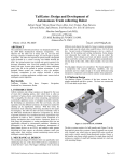
Design and Development of an Ultrasonic
Navigation System
Laurea Magistrale in Ingegneria dell'Automazione
Scuola di Ingegneria dell’Informazione
Politecnico di Milano
Relatore: Prof. Alberto Leva
Correlatore: Prof. Ángel Rodríguez Castaño
Autore: Daniel Varela Iglesias
Matricola: 752265
Anno Accademico: 2012/13
A mis padres,
por toda su alegría, toda su confianza
y, sobre todo, por todo su amor
Design and Development of an Ultrasonic Navigation System
Daniel Varela Iglesias
Table of Contents
Abstract ......................................................................................................................................... 4
Introduzione .................................................................................................................................. 5
1 Introduction.............................................................................................................................. 10
2 Problem Statement .................................................................................................................. 12
3 Possible Solutions ..................................................................................................................... 16
3.1 Arduino .............................................................................................................................. 16
3.2 PIC...................................................................................................................................... 17
4 Chosen solution ........................................................................................................................ 19
4.1 Sonar ................................................................................................................................. 19
4.1.1 Real-Time Operation and Timing ............................................................................... 20
4.1.2 Real-time Auto Calibration and Noise Rejection ........................................................ 21
4.1.3 Beam Characteristics .................................................................................................. 22
4.2 Stellaris EK-LM4F120XL LaunchPad................................................................................... 22
4.3 Necessary tools ................................................................................................................. 26
4.3.1 TTL-232R cable ........................................................................................................... 27
4.3.2 PuTTY .......................................................................................................................... 29
4.3.3 Code Composer Studio ............................................................................................... 32
4.3.4 FreeRTOS .................................................................................................................... 42
5 Starting Up................................................................................................................................ 46
5.1 Hardware Integration ........................................................................................................ 46
5.2 Programming ..................................................................................................................... 51
5.2.1 Drivers Folder ............................................................................................................. 51
5.2.1 Src Folder.................................................................................................................... 51
6 Results Verification................................................................................................................... 52
7 Bibliography and References.................................................................................................... 53
8 Appendix .................................................................................................................................. 54
8.1 Source Code ...................................................................................................................... 54
8.1.1 Drivers Folder ............................................................................................................. 54
8.1.2 Src Folder ................................................................................................................... 80
8.2 Datasheets....................................................................................................................... 101
1
Laurea Magistrale in Ingegneria dell’Automazione
Politecnico di Milano
Design and Development of an Ultrasonic Navigation System
Daniel Varela Iglesias
List of Figures
Figure 1: Fire risks ....................................................................................................................... 10
Figure 2: Evolution of fire apparatus........................................................................................... 11
Figure 3: Tele-opreation base (a) ................................................................................................ 12
Figure 4: 4x4 BOBCAT (a) ............................................................................................................ 13
Figure 5: Modifications implementation on the fire apparatus.................................................. 13
Figure 6: 4x4 BOBCAT (b) ............................................................................................................ 14
Figure 7: Tele-opreation base (b) ................................................................................................ 14
Figure 8: MaxSonar MB1220 ....................................................................................................... 19
Figure 9: MaxSonar dimensions .................................................................................................. 20
Figure 10: Beam characteristics .................................................................................................. 22
Figure 11: Stellaris EK-LM4F120XL LaunchPad............................................................................ 23
Figure 12: Architecture of the microcontroller ........................................................................... 25
Figure 13: Communication with Virtual COM Port ..................................................................... 28
Figure 14: Communication with D2XX ........................................................................................ 28
Figure 15: TTL-232R 6 way header pin-out ................................................................................. 29
Figure 16: PuTTY configuration window ..................................................................................... 30
Figure 17: Sonar communication parameters (a) ....................................................................... 30
Figure 18: Sonar communication parameters (b) ....................................................................... 31
Figure 19: Computer communication parameters...................................................................... 31
Figure 20: Code Composer Studio perspectives ......................................................................... 33
Figure 21: Workspace and Project .............................................................................................. 34
Figure 22: New project window .................................................................................................. 35
Figure 23: Code Composer Studio Edit perspective .................................................................... 36
Figure 24: Adding files ................................................................................................................. 37
Figure 25: Link or copy ................................................................................................................ 37
Figure 26: Edit example ............................................................................................................... 38
Figure 27: ARM compiler............................................................................................................. 39
Figure 28: ARM linker .................................................................................................................. 39
Figure 29: Build options configured ............................................................................................ 40
Figure 30: Debug perspective ..................................................................................................... 41
Figure 31: Block diagram ............................................................................................................. 46
Figure 32: Protoboard connection (a) ......................................................................................... 47
Figure 33: Wired sensors............................................................................................................. 47
Figure 34: Protoboard connection (b) ......................................................................................... 47
Figure 35: Perfboard connection (a) ........................................................................................... 48
Figure 36: Perfboard connection (b) ........................................................................................... 49
Figure 37: Communications Module (a) ...................................................................................... 49
Figure 38: Communications Module (b) ..................................................................................... 50
Figure 39: Communications Module (c) ...................................................................................... 50
Figure 40: Perfboard connection (c) ........................................................................................... 50
Figure 41: PuTTY results .............................................................................................................. 52
2
Laurea Magistrale in Ingegneria dell’Automazione
Politecnico di Milano
Design and Development of an Ultrasonic Navigation System
Daniel Varela Iglesias
List of Tables
Table 1: Stellaris description ....................................................................................................... 24
Table 2: Stellaris IDEs .................................................................................................................. 26
Table 3: TTL-232R pin-out description ........................................................................................ 29
3
Laurea Magistrale in Ingegneria dell’Automazione
Politecnico di Milano
Design and Development of an Ultrasonic Navigation System
Daniel Varela Iglesias
Abstract
In 2009, the ITURRI Group began an ambitious R&D project. The goal was to have
in-house technology which enables unmanned vehicles to be operated remotely.
The idea behind it is to avoid putting human lives at risk when it is necessary to
drive a vehicle into an area in which the safety of its occupants is not guaranteed.
There are multiple potential uses and applications: from operations in which there are
NBQ threats to military operations in which there are snipers; also in the extinguishing
of forest fires, fires at petrochemical plants, etc.
The project, called SICTEL (Tele-operated Conduction Integral System), was
presented to the Centre for Industrial Technological Development (CDTI), a public
entity which depends on the Ministry of Economics and Competitivity and promotes
technological innovation and development of Spanish companies. It was welcomed
with such interest that it has been financed by the Technology Fund, a special tranche
of ERDF funding from the European Union dedicated to the promotion of business
R&D in Spain.
As part of that project, we have been proposed to design and develop an
obstacle avoidance system for unmanned vehicles using four ultrasonic sensors.
4
Laurea Magistrale in Ingegneria dell’Automazione
Politecnico di Milano
Design and Development of an Ultrasonic Navigation System
Daniel Varela Iglesias
Introduzione
Nel 2009, il gruppo ITURRI cominciò un ambizioso progetto R&S, il cui obiettivo
era di disporre di una tecnologia propria che permitesse di operare veicoli a distanza
senza pilota.
Si trattava di non rischiare vite umane in caso fosse necessario approssimare un
veicolo in una zona dove la sicurezza dei suoi occupanti non fosse garantita. Gli usi
potenziali e le applicazioni possono essere diversi da operazioni nelle quali esistono
rischi NBQ (Nuclear, Biological, Chemical) a operazioni militari con la possibile presenza
di cecchini; anche nell’estinzione di incendi boschivi, piante petrochimiche, etc.
Il progetto, chiamato SICTEL (Tele-operated Conduction Integral System), fu
presentato al Centro per lo Sviluppo Tecnologico Industriale (CDTI), un’entità pubblica
che dipende dal Ministero di Economia e Competitività e promuove l’innovazione
tecnologica e lo sviluppo nelle aziende spagnole. Fu accolto con così tanto interesse
che è stato finanziato dal Fondo Tecnologico, una parte speciale dei fondi FEDER
dell’Unione Europea dedicata alla promozione della R&S aziendale in Spagna.
Come risultato, il progetto SICTEL dispone di un veicolo leggero ed uno pesante,
che contano con la capacità di essere operati in distanza e senza perdere la capacità di
essere guidati in forma convenzionale con un conducente in cabina. Questo fornisce
una possibilità duale per il suo uso a seconda dalle necessità del momento.
Il veicolo leggero è un prototipo a trazione integrale (4x4) chiamato BOBCAT, che
è stato modificato meccanicamente ed elettronicamente. Sebbene ha rappresentato
una sfida tecnologica significativa dovuta alla sua capacità iniziale di automazione, il
risultato ottenuto con il veicolo pesante è stato più spettacolare. Consiste in un veicolo
anche a trazione integrale che, oltre alla possibilità di guida a distanza senza visione
diretta attraverso le sue telecamere di visione diurna e notturna, permette di attuare a
distanza, abilitando un albero di illuminazione ed un idrante per estinguere un
incendio a parecchie centinaia di metri di distanza senza conducente in cabina.
Dopo quattro anni di sviluppo il progetto si trova nella fase finale ed entrambi i
veicoli furono presentati al CTDI nel Luglio 2012 ed il progetto ebbe un grande
successo.
5
Laurea Magistrale in Ingegneria dell’Automazione
Politecnico di Milano
Design and Development of an Ultrasonic Navigation System
Daniel Varela Iglesias
Come parte di questo progetto, ci hanno proposto di disegnare e sviluppare un
sistema di rilevamento di oggetti per veicoli senza pilota usando quattro sensori ad
ultrasuoni.
Dopo aver scartato altre opzioni come Arduino o PIC, abbiamo deciso di utilizzare
il LaunchPad Stellaris EK-LM4F120XL della compagnia Texas Instruments, che ci offre
uno strumento molto potente ad un costo veramente basso.
Dobbiamo considerare che anche se questo dispositivo è nel mercato da poco
tempo (all’incirca da un anno), presenta una grande varietà di possibilità.
Oltre al suo prezzo e alle possibilità che offre, abbiamo scelto questo dispositivo
per la comodità di poter utilizzare il linguaggio C per la sua programmazione. Inoltre,
sul sito di Texas Instruments, è disponibile una grande quantità di documentazione e
manuali da consultare, in aggiunta a un forum molto attivo, dove gli utenti possono
risolvere i loro dubbi.
In primo luogo, e per prendere familiarità con il dispositivo, abbiamo realizzato
una serie di tutorial di iniziazione che ci hanno dato l’informazione elementare
necessaria per programmare il dispositivo, realizzare compiti basilari, come
accendere/spegnere un LED o una comunicazione semplice tra il nostro computer ed il
Launchpad.
Lo strumento principale che abbiamo utilizzato è stato il software Code
Composer Studio, che si può scaricare gratuitamente dal sito di Texas Instruments. È
importante sapere che questa scelta non è stata fatta a caso, visto che i
microcontrollori Stellaris sono tollerati anche da altri IDEs (Integrated Development
Environments) di aziende come Mentor Graphics, IAR Systems e ARM KEIL. Fra tutte
queste possibile scelte, Code Composer Studio è l’unica che non impone limitazioni di
tempo di uso o quantità di memoria destinata al codice sorgente. Se si volesse un
aggiornamento completo (che non è stato necessario per il nostro progetto),
risulterebbe l’opzione più economica.
Gli altri strumenti utilizzati per il nostro progetto sono:
Cavo TTL-232R: i cavi TTL-232R sono una famiglia di convertitori USB to TTL
seriale UART che incorporano interfaccia FTDI’s FT232RQ USB to Serial UART IC
(In Circuit), che gestisce tutta la segnalazione e protocolli USB. I cavi procurano
un modo veloce e semplice per collegare dispositivi con una interfaccia a livelli
TTL seriale a USB.
Oggigiorno i computer non includono il serial port. Per questa ragione sarà
usato un cavo TTL-232R, in primo luogo per creare una comunicazione tra il
computer ed il sensore e verificare come i dati sono inviati; ed in secondo luogo
6
Laurea Magistrale in Ingegneria dell’Automazione
Politecnico di Milano
Design and Development of an Ultrasonic Navigation System
Daniel Varela Iglesias
per collegare il computer con il Launchpad e ricevere la struttura con
l’informazione dei quattro sensori.
Per capire come lavora il sensore e per comunicare con esso, avremo bisogno
non solo di uno oscilloscopio. Dopo le prime prove sui pin del sensore
dovevamo considerare quale di questi pin forniva i risultati migliori.
Il sensore fornisce la misura della distanza in tre pin diversi: attraverso
un’uscita analogica (AN), attraverso la larghezza di impulso (PW) ed attraverso
lo standard RS-232 (TX).
Le due prime opzioni presentarono problemi, per questo motivo è stato scelto
lo standard RS-232.
PuTTY: è un open-source terminal emulator gratuito. Supporta diversi
protocolli di rete, includendo SCP, SSH, Telnet e rlogin.
PuTTY fu originariamente scritto per Microsoft Windows, però è stato
introdotto ad altri sistemi operativi. I port ufficiali sono disponibili per alcune
piattaforme Unix-like, con work-in-progress ports to Classic Mac OS e Mac OS
X, e ports non ufficiali hanno contributo in piattaforme come Symbian e
Windows Mobile.
Da quando Windows Vista è stato pubblicato, Microsoft non include più il
software HyperTerminal.
Stellaris Launchpad: il dispositivo include un processore ARM Cortex-M4F che
opera a 80 MHz. Ha una memoria di 256 KB single-cycle Flash, 32 KB singlecycle SRAM, 2KB of EEPROM e Internal ROM caricata con StellarisWare®
software.
Per le interfacce di comunicazioni ha: otto UARTs, quattro moduli SSI, quattro
moduli I2C con quattro velocità di trasmissione includendo high-speed mode,
controllori CAN 2.0 A/B e USB 2.0 Device.
In quanto al sistema di integrazione consta di: ARM® PrimeCell® 32-canali con
controllore configurabile μDMA, sei blocchi 16/32-bit GPTM e sei blocchi
32/64-bit Wide GPTM, due watchdog timers, un modulo di ibernazione lowpower battery-backed e sei blocchi fisichi GPIO.
7
Laurea Magistrale in Ingegneria dell’Automazione
Politecnico di Milano
Design and Development of an Ultrasonic Navigation System
Daniel Varela Iglesias
Supporto analogico: due moduli 12-bit ADC con massimo sample rate di un
milione di samples/second, due comparatori analogici indipendenti integrati,
sedici comparatori digitali, un modulo JTAG con ARM SWD integrato e 64-pin
LQFP.
FreeRTOS: è uno dei prodotti leader del mercato dei sistemi operativi in tempo
reale (RTOS) ed è stato creato da Engineers Ltd. Supporta 33 architetture
diverse, è stato sviluppato professionalmente, con qualità controllata
strettamente, robusto e gratuito per l’uso in prodotti commerciali, senza dover
esporre il codice sorgente del propietario.
È stato disegnato per essere sufficientemente piccolo per funzionare in un
microcontrollore, anche se il suo uso non è limitato alle applicazioni per
microcontrollori.
I microcontrollori sono usati ampiamente in applicazioni embedded che
normalmente svolgono compiti molto specifici. I limiti dimensionali e la natura
dedicata delle applicazioni raramente giustifica l’uso di un RTOS completo.
Pertanto, FreeRTOS offre soltanto la funzionalità della pianificazione in tempo
reale del core, la comunicazione tra compiti, la distribuzione nel tempo e la
sincronizzazione. Questo significa che sarebbe più correttamente definito come
un real-time kernel, o real-time executive. Funzionalità aggiuntive come
command console interface o networking stacks possono essere incluse con
componenti aggiuntivi.
Include una minima ROM, RAM e processing overhead. Solitamente l’immagine
binaria di un kernel RTOS sarà nella regione tra 4KB e 9KB. Il core del kernel del
RTOS è contenuto in solo tre file. La maggior parte dei numerosi file inclusi nel
file .zip collegano le numerose applicazioni di dimostrazione.
Le prove del Launchpad si sono fatte con l’aiuto di una protoboard, non solo per
la facilità di collegamento dei cavi ma anche perchè è stato necessario invertire l’uscita
dei sensori, come era specificato nel datasheet.
Una volta che il dispositivo è programmato, dovremo integrarlo nel veicolo, e per
questo abbiamo creato un piccolo circuito usando una perfboard per due motivi
importanti:
Spazio: visto che stiamo lavorando con un prototipo, dovremo avere spazio
sufficiente per maneggiare l’hardware. Questo comporta il collegamento e
scollegamento dei cavi parecchie volte ed il trasporto dei dispositivi per fare le
prove. In questi casi è preferibile facilitare queste azioni invece di danneggiare i
circuiti.
8
Laurea Magistrale in Ingegneria dell’Automazione
Politecnico di Milano
Design and Development of an Ultrasonic Navigation System
Daniel Varela Iglesias
Inoltre, visto che il Launchpad Stellaris ha appena spazio per essere attaccato,
possiamo inserire la nostra perfboard e collegarla dove sia necessario.
Livelli di tensione: come abbiamo menzionato prima, il sensore ha un pin che
manda l’informazione in forma asincrona con un formato RS232. Come però è
specificato nel datasheet, i livelli di tensione sono tra 0 e Vcc che sono fuori
dallo standrd RS232. Per questo motivo dobbiamo invertire il segnale di ogni
sensore, in modo da ottenere i livelli desiderati.
9
Laurea Magistrale in Ingegneria dell’Automazione
Politecnico di Milano
Design and Development of an Ultrasonic Navigation System
Daniel Varela Iglesias
1 Introduction
Historically, the human being has delegated certain kind of works to machines
for reasons like benefit, efficiency and comfort. But one of the main motivating ideas
has always been using the machines to reduce the danger and the possible risk to the
human lives. Based on that idea, the evolution of the machines concerning to the
safety has supposed, in most of the cases, a parallel transformation to the productivity
and efficiency.
Of course not all the machines entail the same level of danger because that
would depend on the activity that the machine is destined to. For example, a licenseplate scanner in a parking would imply less hazards than the control system for
railroad gate. But in any case, the risk would be always there due to that human factor.
Another important fact to bear in mind is the work environment. There are
machines that can achieve their work in all the possible surroundings (offices,
factories, open spaces or even the nature).
Throughout history one of the greatest tools that has differenced the human
being from the rest of the species has been the use of the fire for its own benefit, such
as the heat, the illumination or the protection against other species. But sometimes
the proper greatness of this tool makes it uncontrollable and ends up with disasters.
The consequences of a fire, even if it is small, are widely known. They devastate
anything, reducing it to ashes, no matter if they are homes, forests or lives.
Figure 1: Fire risks
Due to the big magnitude of this kind of disasters, the human being has always
tried to face them up but with the disadvantage of transporting the fire-fighting
material where the fire is. With that idea the fire apparatus were created. We have to
clarify that by fire apparatus we mean general terms. A truck could be almost any
vehicle used by the fire department, but the term has become specialised over the
years. Originally, “engine” referred exclusively to “pump”, the important tool for
10
Laurea Magistrale in Ingegneria dell’Automazione
Politecnico di Milano
Design and Development of an Ultrasonic Navigation System
Daniel Varela Iglesias
getting water to a fire. Today, fire engines are those vehicles of the fire department
that pump water. The term “truck” is reserved for other types of vehicles, usually
having one or more ladders.
Since fire engines and fire trucks perform significantly different functions at a fire
scene, they are very different. Fire engines are equipped with hoses and water so the
personnel can aggressively fight the fire. Fire trucks are like the fire-fighter’s tool box,
carrying ladders, rescue equipment and other tools to enable personnel to support
fire- fighting activities.
Besides of the existence of flying boats or ships that are also used on the firefighting, we will focus on the fire-fighting apparatus. In particular, on those destined
for the forest fire-fighting.
As it has been mentioned along this section, we will have to work with machines
created with the objective of easing the job to the fire-fighting but they include the
human participation. The fires take place on hills, forests, meadows and wide zones
where the wind and the droughts can increase the difficulty of the fire-fighting and the
devastated area in few minutes, most of all if we do not know well the zone.
Unfortunately, it is not low the number of cases where a fireman has been
trapped in a fire and has lost his life because of the loss of orientation or because the
fire has shut all the exit ways.
Going one step further protecting the people that work on this environment, a
new type of fire apparatus arises. It is not an evolution on its mechanical or functional
characteristics, but in the way that the human being would use it. The idea is not to
create a fire-resistant apparatus or with bigger water storage; the idea is to not
directly imply any human life for its management.
Figure 2: Evolution of fire apparatus
11
Laurea Magistrale in Ingegneria dell’Automazione
Politecnico di Milano
Design and Development of an Ultrasonic Navigation System
Daniel Varela Iglesias
2 Problem Statement
In 2009, the ITURRI Group began an ambitious R&D project, orientated from
operations in which there are NBQ threats to military operations in which there are
snipers; also in the extinguishing of forest fires, fires at petrochemical plants, etc.
The project, called SICTEL (Tele-operated Conduction Integral System), was
presented to the Centre for Industrial Technological Development (CDTI), a public
entity which depends on the Ministry of Economics and Competitivity and promotes
technological innovation and development of Spanish companies. It was welcomed
with such interest that it has been financed by the Technology Fund, a special tranche
of ERDF funding from the European Union dedicated to the promotion of business
R&D in Spain.
As part of that project, we have been proposed to perform an object detection
system for an unmanned vehicle using four ultrasonic sensors.
The system will be applied on a 4x4 prototype vehicle called BOBCAT, which has
been modified mechanically and electronically. Subsequently the system will be
integrated in a real fire apparatus, that could be driven from a tele-operation base and
follow previously defined paths.
Figure 3: Tele-opreation base (a)
12
Laurea Magistrale in Ingegneria dell’Automazione
Politecnico di Milano
Design and Development of an Ultrasonic Navigation System
Daniel Varela Iglesias
Figure 4: 4x4 BOBCAT (a)
The choice of the communication interface between the sensors and the central
computer of the vehicle would be under our supervision. Due to that, we would
evaluate the possible solutions and select the one that fits better to our requirements.
Therefore, a system that takes the information from the four sensors to a
module would be needed. This module would communicate with the central computer
to send a frame that contains all the data together.
In the next sections the possible solutions among which we could opt and some
of their characteristics would be described.
Figure 5: Modifications implementation on the fire apparatus
At present, after four years of development, the whole project is on its final
stage. All the mechanical modifications used on the BOBCAT have been already applied
on the fire apparatus.
13
Laurea Magistrale in Ingegneria dell’Automazione
Politecnico di Milano
Design and Development of an Ultrasonic Navigation System
Daniel Varela Iglesias
Figure 6: 4x4 BOBCAT (b)
Figure 7: Tele-opreation base (b)
On the electronic aspect, some additional modifications were needed to control
new aspects that were not present on the BOBCAT, like the hose or the gearbox, due
to its more powerful motor.
On the other hand, the software has been the part of the project that has
suffered more delays. This is because of until the modifications were implemented to
the fire apparatus the software of the control system could not be tested. Despite of
that fact, we can say that the software is already on its integration stage, and therefore
numerous tests have been already made, with a very satisfactory result.
Even if we are working on a specific design, the project is open to future
modifications with the idea of increasing its abilities and possibilities. Among those
modifications, that are already considered for the next prototype, we should remark:
14
Laurea Magistrale in Ingegneria dell’Automazione
Politecnico di Milano
Design and Development of an Ultrasonic Navigation System
Daniel Varela Iglesias
Soldier mode: the vehicle will be able to follow another vehicle situated in front
of it. In this way, it would be able to place an elevated number of units just
driving or tele-operating the first vehicle of the line, which would act as a guide
for the rest.
Multiple tele-operation bases: there would be a main tele-operation base, from
which we would monitor the state of the vehicle. Additionally, we could
connect other secondary operation bases, smaller than the main one, which
would receive images from the tele-cameras as well as data from the systems
on board.
Multiple vehicle control: the idea is to control several vehicles with the same
operation base, so we will not need an operation base for each one.
Both vehicles were presented to the CDTI in July 2012 with a great success.
15
Laurea Magistrale in Ingegneria dell’Automazione
Politecnico di Milano
Design and Development of an Ultrasonic Navigation System
Daniel Varela Iglesias
3 Possible Solutions
3.1 Arduino
Arduino has been presented as a solution for many learning problems and
interaction of the student with the technology. This pre-armed platform has been
getting interest in the last years. The fact of using open source, its facility to develop
interactive elements and the possibility of starting to use it without previous
knowledge about electronics make that, at least, is interesting to analyse.
With Arduino we have the possibility of mounting the board ourselves, just
following some simple instructions that we can find in the tutorials. But in case we are
not familiar with using a soldering iron, we can buy it already mounted.
The first PCBs (Printed Circuit Board) used the ATmega8 microcontroller, made
by Atmel and they had a voltage regulator, a reset switch, an ICPS (In Circuit Serial
Program), ADC (Analog to Digital Converter) inputs, some digital I/O (input/output) and
a serial RS232 bus or USB port. Afterwards, the ATmega168 was introduced to
substitute the previous microcontroller.
The great advantage of using Arduino resides on the already done work that
offers, so the user just has to “put” them together. As a result, we would have a quick
exit in the case we want to work with microcontrollers.
Nevertheless, that great advantage is palliated by certain lacks that become
visible if we compare Arduino with PIC microcontrollers of the Microchip company. In
the following paragraphs we will describe some of them.
Price: the ATmega168 and the typical PIC16F876A are very similar in this
aspect. But bearing in mind that the bibliography, support and help (not just in
the official website but also in the Internet forums) that we can find about the
PIC is far wider than the ATmega, it would be preferable to use a PIC.
Language: Arduino microcontrollers are programmed in C, which represents a
clear attribute for the easiness of programming them. And the same language
can be used for programming the PICs through CCS (Custom Computer
Services).
The inconvenient is that CCS, which is worldwide used, is not compatible for
programming Arduino.
In addition, PICs can be also programmed in assembly language using MPLAB,
the Microchip’s IDE (Integrated Development Environment). Therefore we
would have a better control over the microcontroller.
16
Laurea Magistrale in Ingegneria dell’Automazione
Politecnico di Milano
Design and Development of an Ultrasonic Navigation System
Daniel Varela Iglesias
Reliability: the radiofrequency native systems that some PICs have (rfPIC) are
more reliable than the solution that Arduino implements, that is mounting a
module like they do with the Bluetooth.
Functionality: any task that can be done using Arduino can be performed also
with a PIC (not even using the 18F family, but also with a 16F876A).
Unfortunately, there are lots of operations that cannot be done with Arduino.
Flexibility: comparing Arduino with PIC is not like comparing Linux with
Windows. Linux offers more flexibility and ability to create. In Arduino those
characteristics simply do not exist, hence, we are restricted to what the
hardware allows us.
On its last version, the Arduino Due, an 84MHz Atmel SAM3X8E microprocessor
is been used, based on a 32-bit ARM Cortex-M3 architecture, 3’3V supplied voltage.
That represents an improvement over the previous version, the 16MHz Arduino
Mega2560 with 5V supplied voltage.
Nevertheless, the previous problems that we have mentioned before are enough
for not choosing this option. As we will see later, we will use a more powerful
microcontroller and three times cheaper.
3.2 PIC
After dismissing Arduino, the possibility of using a PIC was our second option,
basically due to the reasons that have been explained on the previous section.
The fact of we would have to determine the communication interface between
the devices made us consider the option of using the PIC18F2580. Because, in the case
it would be needed, we could use the CAN (Controller Area Network) bus.
Initially, this seemed to be the best option, due to we could count with a lot of
information about PICs and the use of the CAN bus. Besides, as we have mentioned
before, we could implement the code in C language.
However, the CAN bus management with PIC becomes difficult, and in the case
we would need to use this protocol it would draw out the developing time of our
project.
It could seem we are avoiding options just because it could be hard to put them
in practice. But we have to bear in mind that, as we will do in the future, we should
17
Laurea Magistrale in Ingegneria dell’Automazione
Politecnico di Milano
Design and Development of an Ultrasonic Navigation System
Daniel Varela Iglesias
select the option that fits better to our requirements and deadlines are certainly one
of the most important factors to consider.
A delay on the delivery date of a product that comes out to the market just
because we did not choose a feasible and faster solution could have negative
consequences on the company that offers that product. Therefore, we should pay
attention and decide if our idea is worthwhile.
18
Laurea Magistrale in Ingegneria dell’Automazione
Politecnico di Milano
Design and Development of an Ultrasonic Navigation System
Daniel Varela Iglesias
4 Chosen solution
4.1 Sonar
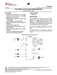
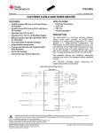
The XL- MaxSonar®- EZ2™ (MB1220) is a sonar range finder with high power
output, noise rejection, auto calibration and medium-range medium detection zone.
The MB1220 has a new high power output along with real-time auto calibration
for changing conditions (temperature, voltage and acoustic or electrical noise) that
ensure us receive the most reliable (in air) ranging data for every reading taken.
The MB1220 low power 3.3V – 5V operation provides very short to long-range
detection and ranging, in a tiny and compact form factor. The MB1220 detect objects
from 0 cm† to 765 cm and provide sonar range information from 20 cm out to 765 cm
with 1 cm resolution. Objects from 0 cm to 20 cm typically range as 20 cm.
The interface output formats included are pulse width output (MB1220), realtime analog voltage envelope (for the MB1320), analog voltage output, and serial
digital output.
Figure 8: MaxSonar MB1220
The following points define the pin out of the sensor:
†
Pin 1: we should leave it open (or high) for serial output on the Pin 5 output.
When Pin 1 is held low the Pin 5 output sends a pulse (instead of serial data),
suitable for low noise chaining.
Pin 2: for MB1220 (PW) this pin outputs a pulse width representation of range.
To calculate distance, we have to use the scale factor of 58uS per cm.
For MB1320 (AE) this pin outputs the analog voltage envelope of the acoustic
wave form.
Objects from 0 mm to 1 mm may not be detected
19
Laurea Magistrale in Ingegneria dell’Automazione
Politecnico di Milano
Design and Development of an Ultrasonic Navigation System
Daniel Varela Iglesias
Pin 3: (AN) this pin outputs analog voltage with a scaling factor of (Vcc/1024)
per cm. A supply of 5V yields ~4.9 mV/cm., and 3.3V yields ~3.2 mV/cm.
Hardware limits the maximum reported range on this output to ~700 cm at 5V
and ~600 cm at 3.3V. The output is buffered and corresponds to the most
recent range data.
Pin 4: (RX) this pin is internally pulled high. The MB1220 will continually
measure range and output if the pin is left unconnected or held high. If held
low the MB1220 will stop ranging. Bring high 20uS or more for range reading.
Pin 5: (TX) when Pin 1 is open or held high, the Pin 5 output delivers
asynchronous serial with an RS232 format, except voltages are 0 - Vcc. The
output is an ASCII capital “R”, followed by three ASCII character digits
representing the range in centimetres up to a maximum of 765, followed by a
carriage return (ASCII 13). The baud rate is 9600, 8 bits, no parity, with one stop
bit. Although the voltage of 0 - Vcc is outside the RS232 standard, most RS232
devices have sufficient margin to read 0 - Vcc serial data. If standard voltage
level RS232 is desired, we have to invert, and connect an RS232 converter such
as a MAX232. When Pin 1 is held low, the Pin 5 output sends a single pulse,
suitable for low noise chaining (no serial data).
V+: operates on 3.3V - 5V. The average (and peak) current draw for 3.3V
operation is 2.1mA (50mA peak) and at 5V operation is 3.4mA (100mA peak)
respectively. Peak current is used during sonar pulse transmit.
GND: Return for the DC power supply. GND (and V+) must be ripple and noise
free for best operation.
Figure 9: MaxSonar dimensions
4.1.1 Real-Time Operation and Timing
175 ms after power-up, the XL-MaxSonar® is ready to begin ranging. If Pin 4 is
left open or held high (20 μs or greater), the sensor will take a range reading. The XL20
Laurea Magistrale in Ingegneria dell’Automazione
Politecnico di Milano
Design and Development of an Ultrasonic Navigation System
Daniel Varela Iglesias
MaxSonar® checks the Pin 4 at the end of every cycle. Range data can be acquired
once every 99 ms. Each 99 ms period starts by Pin 4 being high or open, after which
the XL-MaxSonar® calibrates and calculates for 20.5 ms, and after that, thirteen 42 KHz
waves are sent.
Then for the MB1220, the pulse width (PW) Pin 2 is set high. When an object is
detected the PW pin is set low. If no target is detected the PW pin will be held high for
up to 44.4 ms (i.e. 58 μs * 765 cm). For the most accurate range data, is better to use
the PW output of the MB1220 product.
For the MB1320 with analog envelop output, Pin 2 will show the real-time signal
return information of the analog waveform.
For both parts, the remainder of the 99 ms time (less 4.7 ms) is spent adjusting
the analog voltage to the correct level, (and allowing the high acoustic power to
dissipate). During the last 4.7 ms the serial data is sent.
4.1.2 Real-time Auto Calibration and Noise Rejection
Each time before the XL-MaxSonar® takes a range reading it calibrates itself. The
sensor then uses this data to range objects. If the temperature, humidity, or applied
voltage changes during sensor operation, the sensor will continue to function
normally. The sensor does not apply compensation for the speed of sound change
verses temperature to any range readings.
While the XL-MaxSonar® is designed to operate in the presence of noise, best
operation is obtained when noise strength is low and desired signal strength is high.
Hence, the user is encouraged to mount the sensor in such a way that minimizes
outside acoustic noise pickup. In addition, keep the DC power to the sensor free of
noise.
This will let the sensor deal with noise issues outside of the users direct control
(in general, the sensor will still function well even if these things are ignored). Users
are encouraged to test the sensor in their application to verify usability.
For every ranging cycle, individual filtering for that specific cycle is applied. In
general, noise from regularly occurring periodic noise sources such as motors, fans,
vibration, etc., will not falsely be detected as an object.
This holds true even if the periodic noise increases or decreases (such as might
occur in engine throttling or an increase/decrease of wind movement over the sensor).
Even so, it is possible for sharp non-periodic noise sources to cause false target
21
Laurea Magistrale in Ingegneria dell’Automazione
Politecnico di Milano
Design and Development of an Ultrasonic Navigation System
Daniel Varela Iglesias
detection. In addition, ‡(because of dynamic range and signal to noise physics,) as the
noise level increases, at first only small targets might be missed, but if noise increases
to very high levels, it is likely that even large targets will be missed.
4.1.3 Beam Characteristics
The MB1220 has a wide and long sensitive beam that offers excellent detection
of objects and people. The MB1220 balances the detection of objects and people with
minimal side-lobes. Sample results for measured beam patterns are shown in the next
figure on a 30-cm grid. The detection pattern is shown for dowels of varying diameters
that are place in front of the sensor.
(A) 6.1 mm diameter, (B) 2.54 cm diameter, (C) 8.89 cm diameter
Figure 10: Beam characteristics
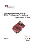
4.2 Stellaris EK-LM4F120XL LaunchPad
At last, we have decided to use the Texas Instruments’ Stellaris LaunchPad EKLM4F120XL, motivated by the problems which have been mentioned before. And
mainly due to the simplicity and possibilities that this device offers.
‡
In high noise environments, we can use 5V power to keep acoustic signal power high. In addition, a high acoustic noise
environment may use some of the dynamic range of the sensor, so we should consider a part with less gain such as the
MB1230/MB1330 or MB1240/MB1340. For applications with large targets, we should consider a part with ultra clutter rejection
like the MB7092.
22
Laurea Magistrale in Ingegneria dell’Automazione
Politecnico di Milano
Design and Development of an Ultrasonic Navigation System
Daniel Varela Iglesias
We have remark that also the price is another good reason for choosing this
LaunchPad (the cost is less than 12€, which is a lot cheaper than the dismissed
options).
Figure 11: Stellaris EK-LM4F120XL LaunchPad
23
Laurea Magistrale in Ingegneria dell’Automazione
Politecnico di Milano
Design and Development of an Ultrasonic Navigation System
Daniel Varela Iglesias
The next table shows a brief description of its characteristics:
Feature
Description
Core
Performance
Flash
System SRAM
EEPROM
Internal ROM
ARM Cortex-M4F processor core
80-MHz operation; 100 DMIPS performance
256 KB single-cycle Flash memory
32 KB single-cycle SRAM
2KB of EEPROM
Internal ROM loaded with StellarisWare®
software
Communication Interfaces
Universal Asynchronous Receivers/Transmitter
(UART)
Synchronous Serial Interface (SSI)
2
Inter-Integrated Circuit (I C)
Controller Area Network (CAN)
Universal Serial Bus (USB)
Eight UARTs
Four SSI modules
2
Four I C modules with four transmission speeds
including high-speed mode
CAN 2.0 A/B controllers
USB 2.0 Device
System Integration
Micro Direct Memory Access (μDMA)
ARM® PrimeCell® 32-channel configurable
μDMA controller
Six 16/32-bit GPTM blocks and six 32/64-bit
Wide GPTM blocks
Two watchdog timers
Low-power battery-backed Hibernation module
Six physical GPIO blocks
General-Purpose Timer (GPTM)
Watchdog Timer (WDT)
Hibernation Module (HIB)
General-Purpose Input/Output (GPIO)
Analog Support
Analog-to-Digital Converter (ADC)
Two 12-bit ADC modules with a maximum
sample rate of one million samples/second
Two independent integrated analog
comparators
16 digital comparators
One JTAG module with integrated ARM SWD
64-pin LQFP
Industrial (-40°C to 85°C) temperature range
Analog Comparator Controller
Digital Comparator
JTAG and Serial Wire Debug (SWD)
Package
Operating Range
Table 1: Stellaris description
For detailed information we can consult the documentation that has been
attached to the Appendix.
24
Laurea Magistrale in Ingegneria dell’Automazione
Politecnico di Milano
Design and Development of an Ultrasonic Navigation System
Daniel Varela Iglesias
The following figure illustrates the architecture of the microcontroller:
Figure 12: Architecture of the microcontroller
Stellaris microcontrollers are
Development Environments (IDEs):
supported
by
four
Mentor Graphics-Mentor Embedded Code Sourcery tool.
IAR Systems Embedded Workbench tools.
ARM KEIL Microvision tool.
different
Integrated
25
Laurea Magistrale in Ingegneria dell’Automazione
Politecnico di Milano
Design and Development of an Ultrasonic Navigation System
Daniel Varela Iglesias
Texas Instruments Code Composer Studio tool.
Table 2: Stellaris IDEs
As we can see in the previous table some of them offer 30 day full function;
some of them are code size limited. The Code Composer Studio version is full function,
but it's on board emulation limited. If we use and connect the LaunchPad board to our
computer, we will have full function capability of Code Composer Studio. So we don’t
need to actually buy the tool, even if it’s cheaper than the other options.
Texas Instruments has its own C/C++ compiler. In spite of that, C++ is not
supported on embedded market controllers due to the large sizes that it can generate.
For the IDE, Code Composer Studio offers Eclipse-based support, which is a
widespread open source workbench tool.
As some of the other companies, Code Composer Studio offers a JTAG debugger.
In the table is shown the price of the XDS100 as entry level tool for about 60€. But they
also offer the 200 and the 500 that have additional capabilities at an additional cost.
4.3 Necessary tools
Even if this device is practically new (it was released on September 2012) a good
amount of information about it can be found. From the Texas Instruments website is
possible to download all the necessary documentation related to the product and
around six hours of video-tutorials that would be useful with the first steps.
Additionally, Texas Instruments counts with a very active forum where the users
can consult and solve their doubts.
26
Laurea Magistrale in Ingegneria dell’Automazione
Politecnico di Milano
Design and Development of an Ultrasonic Navigation System
Daniel Varela Iglesias
It is possible to download all the needed software to program the device as well.
The main tool that we are going to use is the Code Composer Studio, which will be
described as we will soon see. But first we have to know more about the sensor we
have been given.
4.3.1 TTL-232R cable
In order to understand how the sensor works and to communicate with it, we
will need more than an oscilloscope and a power supply. After the first tests of the
sensor pins we had to consider which one of them would provide the better results.
As it has been detailed before we could opt among Pin 3 (which provides an
analog output, AN), Pin 2 (with a pulse width, PW) and Pin 5 (RS232 transmitter, TX).
The problem with Pin 3 is, as we could read, is that the hardware limits the
maximum reported range to 700 cm approx. with 5V. So in the best case we already
lose 65 cm.
Working with Pin 2 seemed a very good option. In that case we just had to
program interrupts to count the width of the pulses and convert the measures into
distances. This solution seems unnecessary if we compare it with using Pin 5, because
it already provides the distance.
Nowadays computers do not include the serial port. For that reason a TTL-232R
cable will be used, firstly to communicate with the sensor and check how the data is
sent; and secondly to communicate with the LaunchPad to receive the frame with the
information from the four sensors.
The TTL-232R cables are a family of USB to TTL serial UART converter cables
incorporating FTDI’s FT232RQ USB to Serial UART interface IC device which handles all
the USB signalling and protocols. The cables provide a fast, simple way to connect
devices with a TTL level serial interface to USB.
Each TTL-232R cable contains a small internal electronic circuit board, utilising
the FT232R, which is encapsulated into the USB connector end of the cable. The other
end of the cable comes with a selection of different connectors supporting various
applications (in the Appendix there is more information about the other cables).
Cables are FCC, CE, RoHS compliant and are available at TTL levels of +5V and
+3.3V.
Cables are available with either a 6-way SIL (Single In Line), 0.1” pitch connector,
a 3.5mm Audio Jack, an 8 way, keyed 2mm pitch connector (intended for use with
VMUSIC2 or VDRIVE2) or bare, tinned wire ended connections.
The USB side of the cable is USB powered and USB 2.0 full speed compatible.
Each cable is 1.8m long and supports a data transfer rate up to 3 Mbaud. Each cable
27
Laurea Magistrale in Ingegneria dell’Automazione
Politecnico di Milano
Design and Development of an Ultrasonic Navigation System
Daniel Varela Iglesias
supports the FTDIChip-ID™, with a unique USB serial number programmed into the
FT232R. This feature can be used to create a security or password protected file
transfer access using the cable.
The TTL-232R cables require USB drivers, which are used to make the FT232R
cable appear as a virtual COM port (VCP). This then allows the user to communicate
with the USB interface via a standard PC serial emulation port (for example TTY).
Figure 13: Communication with Virtual COM Port
Another FTDI USB driver, the D2XX driver, can also be used with application
software to directly access the FT232R on the cable though a DLL as is shown in the
next image.
Figure 14: Communication with D2XX
For our project we will use the TTL-232R-3V3-WE, which is similar to the TTL232R-5V-WE. Both cables are un-terminated, they are bare and tinned wires. The
difference between the two cables is that the TTL-232R-5V-WE operates at +5V levels
(signals and power supply) and the TTL-232R-3V3-WE operates at +3.3V levels (signals
only, VCC=+5V).
28
Laurea Magistrale in Ingegneria dell’Automazione
Politecnico di Milano
Design and Development of an Ultrasonic Navigation System
Daniel Varela Iglesias
The following figure shows the cable signals and the wire colours for these
signals on the TTL-232R- 5V-WE and TTL-232R-3V3-WE cables.
Figure 15: TTL-232R 6 way header pin-out
Colour
Name
Type
Black
Brown
Red
Orange
Yellow
Green
Red
GND
CTS#
VCC
TXD
RXD
RTS#
VCC
GND
Input
Output
Output
Input
Output
Output
Description
Device ground supply pin
Clear to Send Control input / Handshake signal
+5V output
Transmit Asynchronous Data output
Receive Asynchronous Data input
Request To Send Control Output / Handshake signal
+5V output
Table 3: TTL-232R pin-out description
4.3.2 PuTTY
PuTTY is a free open-source terminal emulator, serial console and network file
transfer application. It supports several network protocols, including SCP, SSH, Telnet
and rlogin.
PuTTY was originally written for Microsoft Windows, but it has been ported to
various other operating systems. Official ports are available for some Unix-like
platforms, with work-in-progress ports to Classic Mac OS and Mac OS X, and unofficial
ports have been contributed to platforms such Symbian and Windows Mobile.
Since Windwos Vista was released, Microsoft no longer includes HyperTerminal.
29
Laurea Magistrale in Ingegneria dell’Automazione
Politecnico di Milano
Design and Development of an Ultrasonic Navigation System
Daniel Varela Iglesias
The next image shows the configuration window.
Figure 16: PuTTY configuration window
Instead of entering every time the parameters we need for the communication,
we can save them as sessions as we can see in the next image for the communication
with the sensor.
Figure 17: Sonar communication parameters (a)
30
Laurea Magistrale in Ingegneria dell’Automazione
Politecnico di Milano
Design and Development of an Ultrasonic Navigation System
Daniel Varela Iglesias
Clicking Serial we can consult the communication parameters.
Figure 18: Sonar communication parameters (b)
For the communication between the Launchpad and the computer we can
change the Baud Rate.
Figure 19: Computer communication parameters
31
Laurea Magistrale in Ingegneria dell’Automazione
Politecnico di Milano
Design and Development of an Ultrasonic Navigation System
Daniel Varela Iglesias
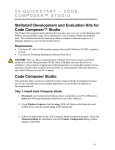
4.3.3 Code Composer Studio
Code Composer Studio is an Integrated Development Environment (IDE) for all of
TI's embedded processors. That includes the debugger, the compiler, the editor, the
simulator and any OS support that we require.
The IDE is built on the Eclipse open source software framework and has been
extended by Texas Instruments to support additional device capabilities.
The version that we are going to use in this project is the 5.2 that is based on an
unmodified version of Eclipse version 3.7.
TI contributes its changes directly to the open source community, rather than
just building it into its tool. So we can drop in Eclipse plug-ins some other vendors, or
we can take TI tools and drop them into an existing Eclipse environment if we want to.
The user can take advantage of all the latest improvements in the Eclipse tool.
Furthermore, additional tools can be integrated: OS level application development
(like for Linux, Android and TI SysBIOS) and also code analysis (third party code
analysis) and source control.
Code Composer Studio runs under Windows and under Linux.
4.3.3.1 Starting with Code Composer Studio
Code Composer Studio has two user interface modes. The first one is a simple
mode. By default, CCS opens up in this simple, basic mode. It is a simplified user
interface to the standard Eclipse perspective, with far fewer menu items and toolbar
buttons. TI supplies these perspectives called CCS Edit and CCS Debug to the tool.
If we want to, we can switch to the advanced mode, which uses the default
Eclipse perspective, that is similar to what existed earlier in Code Composer Studio
version 4.
In the case we are integrating other Eclipse-based tools in the Code Composer
Studio that is the recommended way to proceed.
To switch modes, on the Code Composer menu bar we have to select Window ->
Open Perspective -> Other. And then check the Show All check box, as we can see in
the open perspective dialogue.
32
Laurea Magistrale in Ingegneria dell’Automazione
Politecnico di Milano
Design and Development of an Ultrasonic Navigation System
Daniel Varela Iglesias
Figure 20: Code Composer Studio perspectives
The C/C++ and the Debug are the advanced perspectives.
4.3.3.2 Common Tasks
Some common tasks that might be performed would be:
Creating a new project: it is very simple to create a new project for the device
using templates.
Building options: the build options dialog has been simplified from earlier Code
Composer versions that basically exposed thousands of different options.
Those options are still available, but they are in submenus, which makes this
much easier to walk through the first time.
Updates to those options are delivered with compiler releases. And they are
not dependent on installing an entirely new version of Code Composer .
Sharing projects: it is easier for users to share projects, including working with
version control and making sure that they have portable projects.
Linked sources can be set up. This action has been very much simplified from
earlier Code Composer versions.
4.3.3.3 Workspace and Project
The Eclipse idea of workspaces and projects can be a little odd at first. The next
image would help us to understand how they are related.
33
Laurea Magistrale in Ingegneria dell’Automazione
Politecnico di Milano
Design and Development of an Ultrasonic Navigation System
Daniel Varela Iglesias
Figure 21: Workspace and Project
The workspaces contain the settings and preferences for the way that Eclipse
looks, as well as links to the projects.
In the case we delete a project from the workspace we are deleting the links,
not the files. This is unless we have located or copied our files into the
workspace, which is also possible.
In most cases, we just link our project into the workspace and preserve it. So
as we can see, we could have multiple projects in the workspace. We could
make our settings and preferences, save and export them.
The projects contain our build and tool settings, as well as the links to our
input files.
As we have mentioned in the previous paragraph, deleting files from the
workspace deletes the links, not the files, unless we have located or copied
files in the workspace.
We can link to our project source files, coded data, header files with our
declarations and defines, and any of our library files which has coded data in
them as well.
The best practice way to do this is to link all of those files into our project and
then to link it into the workspace so our original code is preserved for us. Therefore, if
we delete any of them, we will not actually delete the hard worked code that we have
achieved.
The location of the Workspace folder is not really important. But to keep our
projects portable, we should locate it outside the StellarisWare directory.
4.3.3.4 Creating a New Project
New projects are created through the Project Wizard. We can create them from
the Menu Bar clicking File -> New -> CCS Project or Project -> New CCS Project. The
next image shows the New Project dialogue. For the majority of cases, a single page
wizard would appear.
34
Laurea Magistrale in Ingegneria dell’Automazione
Politecnico di Milano
Design and Development of an Ultrasonic Navigation System
Daniel Varela Iglesias
Figure 22: New project window
Clicking the Next button would show up if we have a template that requires
additional settings. In the case showed above, this one does not.
The Debugger set up is all included. We choose the location, the device and the
connection we desire. This will create a modifiable .ccxml file in our project; the idea
is that this is simple by default.
The compiler version, the endianess and all these other advanced settings are in
the advanced settings area and not exposed right here.
As we can see, the name of our project is NewProject and it is an executable
project type.
Generally we will not use the default location (our workspace) but the location
where we have installed the header files and libraries. Of course, unless we have
copied all those files to our workspace
For the Family, we select ARM. To help us select our device faster, in the Variant
box we can type 120. Then, among the other options, we select the Stellaris
LM4F120H5QR.
The connection type, if we are using the LaunchPad or any of the other Stellaris
boards, is the Stellaris In-Circuit Debug Interface.
35
Laurea Magistrale in Ingegneria dell’Automazione
Politecnico di Milano
Design and Development of an Ultrasonic Navigation System
Daniel Varela Iglesias
Below the Device settings, we have some options to pick:
Empty project, which has absolutely nothing in it.
Empty project with a main.c already dropped in.
Assembly only.
DSP/BIOS, which is Texas Instruments’ Real Time Operating System (RTOS).
Another type of project. We could also use some basic examples to start from.
This creates the project for us, drops it in, and all we have to do is get started
editing main.c.
Figure 23: Code Composer Studio Edit perspective
4.3.3.5 Adding Files to the Projects
Once we have created the project, we would probably want to add some
additional files to it.
On the left side, in the Project Explorer, we right click on the name of the project
we have just created and pick Add Files. We can select multiple files if we like, rather
than just one at a time.
36
Laurea Magistrale in Ingegneria dell’Automazione
Politecnico di Milano
Design and Development of an Ultrasonic Navigation System
Daniel Varela Iglesias
Figure 24: Adding files
These files are going to support the activities in our project. Once we select the
file(s) we have two options.
Figure 25: Link or copy
We can copy these files into our workspace. Or we can use them in multiple
projects and just link them into our project, as shown in the previous window. But is
important how do we want to link them, bearing in mind if we want to do it relative to
where our project is located or to where our tools are located.
Summing up, the Add Files option allows us to control how the file is added to
the project. And it is extremely important to know where those files are.
Linking the files using the built-in macros allows us to easily create portable
projects.
Besides the files we may add to our project, another important file we need is
the startup_ccs.c that defines the stack and the interrupt vector table structure,
among other things.
37
Laurea Magistrale in Ingegneria dell’Automazione
Politecnico di Milano
Design and Development of an Ultrasonic Navigation System
Daniel Varela Iglesias
These settings are essential for Code Composer to build our project. As the file is
available in every StellarisWare example, we just have to copy it to our project.
4.3.3.6 Setting the Build Options
The next step would be editing the code in main.c. In the example we have
created a function to blink the RGB LED to see all its colours.
Figure 26: Edit example
In the upper part of the code some question marks appear in the left side of
the include statements. These indicate that Code Composer does not know the path to
these resources.
To solve this, we have to right click on the name of our Project (NewProject) in
the Project Explorer pane and select Properties. Then, on the left under ARM Compiler,
we select Include Options and, in the bottom, where it says Include Search Patch pane,
click on Add. We type the following and click OK.
${PROJECT_ROOT}/../../..
38
Laurea Magistrale in Ingegneria dell’Automazione
Politecnico di Milano
Design and Development of an Ultrasonic Navigation System
Daniel Varela Iglesias
Figure 27: ARM compiler
This path allows the compiler to correctly find the driver lib folder, which is three
levels up from our project folder. Note that if we do not place our project in the
correct location, this link will not work.
Under the ARM linker, we click File Search Path. Then, on the top of the window,
where it says Include Library File, we select Add and type the following:
${PROJECT_ROOT}/../../../driverlib/ccs-cm4f/Debug/driverlib-cm4f.lib
Figure 28: ARM linker
This step allows the linker to correctly find the library file. Again, if we did not
place our project in the correct location, this link will not work either.
39
Laurea Magistrale in Ingegneria dell’Automazione
Politecnico di Milano
Design and Development of an Ultrasonic Navigation System
Daniel Varela Iglesias
Finally we click OK to save our changes. The question marks
If they do, we can adjust the path.
should not appear now.
Figure 29: Build options configured
4.3.3.7 Running the Code
Once we have saved all the work, we are ready to see how it works.
After plug in the Launchpad board, we click the Debug
Composer Studio Menu Bar to build and download the project.
button on the Code
When the process completes, Code Composer Studio will be in the Debug
perspective. The two tabs in the upper right of the screen show the only two predefined perspectives: Debug and Edit. From here we can change to the perspective we
desire, or create as many additional perspectives for our specific needs.
40
Laurea Magistrale in Ingegneria dell’Automazione
Politecnico di Milano
Design and Development of an Ultrasonic Navigation System
Daniel Varela Iglesias
Figure 30: Debug perspective
In this perspective we will be able to use some features that we are going to
describe in the next section.
As we can see in the previous image, below the Debug button we have the
Resume
(to run the code), Suspend
(to pause the code execution) and
Terminate (to return to the Editor perspective) options.
4.3.3.8 Debug perspective
Many options are offered in this perspective. The next points describe them
briefly:
Breakpoints: double clicking on the grey area on the left side of our code we
can insert breakpoints. We have access to all the breakpoints we insert in the
window on the right. From there we can change their properties like, for
example, their Action from Remain Halted (that is the normal way a breakpoint
should act) to Update View (to look up and down in the list).
The current ICDI driver does not support adding/removing breakpoints while
the processor is running.
Registers: clicking on View -> Registers we will be able to see the core and
peripheral register values.
Non-system peripherals that have not been enabled cannot be read.
41
Laurea Magistrale in Ingegneria dell’Automazione
Politecnico di Milano
Design and Development of an Ultrasonic Navigation System
Daniel Varela Iglesias
Memory: clicking on View -> Memory Browser allows us to examine the
memory of the processor. We can can page through memory and click on a
location to directly change the value in that memory location. We can add new
tabs in the case they are not consecutive to have a more comfortable view and
also change the way the data are represented (Hex. 32 bit, 8 bit Binary, etc.).
Expressions: to see the expressions we have to select the variable from the
code and select Add Watch Expression. Updated values are highlighted with a
yellow background.
4.3.4 FreeRTOS
4.3.4.1 Introduction to Real-Time Systems (RTS)
To understand what a real-time system is we have to be familiar with the
concept of time of response for a system. This is the time the system needs to
generate an output associated to an input.
RTS are those where the time needed to generate an output is important.
Generally the input is an event from the outside and the output is the response to that
event.
In a real time system, for having an acceptable functioning, the time that passes
from the input event to the output one must be little enough. That is, the response to
an input has to be obtained in a certain and finite period of time. That time depends
on the system and can be on the order of milliseconds or nanoseconds.
There are two types of RTS:
Hard: when it is very important that the response is obtained within a fixed
time. A delay in that deadline can mean a total system failure.
Soft: when the time is important but is not serious if there is a delay.
On the other hand, we have to distinguish between real-time and interactive
systems. Which are those where a response is awaited in a finite time but that time is
not specified, so is not necessary to response in a fixed time.
RTS are connected to a physical system, which is controlled by the computer.
That is why they are also called integrated systems.
42
Laurea Magistrale in Ingegneria dell’Automazione
Politecnico di Milano
Design and Development of an Ultrasonic Navigation System
Daniel Varela Iglesias
The computer interacts with the physical system through the sensors, that take
the information of the physical system, and actuators, that modify the behaviour of
the physical system.
4.3.4.2 Real-Time Operating Systems (RTOS)
An operating system (OS) is a computer program that supports a computer's
basic functions, and provides services to other programs (or applications) that run on
the computer. The applications provide the functionality that the user of the computer
wants or needs. The services provided by the operating system make writing the
applications faster, simpler, and more maintainable.
The requirements for RTOS are:
Multitask
A real-time operating system must be multitasking, because we would need to
be able to run concurrent processes to obtain a better efficiency of the system. And in
that way achieve with the time restrictions.
In a RTOS is normal to program the multitasking with threads. Each thread would
be in charge of one task in a process.
Preemption
In computing, preemption is the act of temporarily interrupting a task being
carried out by a computer system, without requiring its cooperation, and with the
intention of resuming the task at a later time. Such a change is known as a context
switch. It is normally carried out by a privileged task or part of the system known as a
preemptive scheduler, which has the power to preempt, or interrupt, and later
resume, other tasks in the system.
There are systems in which a task of higher priority can wait for another of lower
priority during an undefined time. That is called priority inversion.
For example, let us assume that we have the tasks T1, T2 and T3, from lower to
higher priority respectively. We suppose that T1 is being executed and T3 is waiting for
T1, because T1 is using a shared resource that T3 needs. For the moment this should
be the normal behaviour: T3 has to wait until T1 stop using the shared resource.
But let us assume now that T2 becomes ready for execution and does not need
any shared resource that T1 is using. Since T2 has higher priority than T1, an interrupt
mechanism would be used to suspend the currently executing process (T1) and to
invoke a scheduler to determine which process should be executed next, that is T2.
43
Laurea Magistrale in Ingegneria dell’Automazione
Politecnico di Milano
Design and Development of an Ultrasonic Navigation System
Daniel Varela Iglesias
Therefore, T3 would be waiting for T2, which has lower priority. That situation is
not normal, and because of that it is called priority inversion.
If T3 would be ready for execution, it would eject T2, which would happen if T3
would have the shared resource that T1 is using. T3 would not be able to take it until
T1 finishes with it, but T1 would not finish with it until T2 ends and T1 can continue its
execution.
That problem can be solved with the priority inheritance. That means we are
going to raise the priority of T1 to equalize T3 meanwhile T1 is using a shared resource
that T3 is waiting. Hence, T1 inherits the priority of T3 and, consequently, would not
eject T1 because T1 would have higher priority.
When T1 stops using the shared resource that T3 is waiting for, its original
priority is assigned again and T3 would start to be executed.
In addition, in RTS is a normal practice that the user decides the priority of the
different tasks, as well as modified them automatically.
Communication and Synchronization
The system must count with fast and flexible mechanisms for the communication
and synchronization between the tasks, because a RTS should manage a lot of them.
In multithreads systems the quickest thing is having a shared memory, so the
global variables can be used by all the threads.
Handle interrupts
The new operating systems that come out nowadays are multithread, but the
first ones were not.
In these new OS all the interrupts are treated like tasks. In that way, the higher
priority process would not be stopped by interrupts that are less important.
Deterministic time
Is a good practice to consider an upper bound for the time that is needed for
some tasks (most of all the critical ones), assuming the worst case. That is even more
important than having a better efficiency in our system.
Therefore, it is better to say that our task will not need more than 50
microseconds rather than it generally takes 35 microseconds, because it could take
more than that. This is particularly of interest to embedded systems as embedded
systems often have real time requirements.
44
Laurea Magistrale in Ingegneria dell’Automazione
Politecnico di Milano
Design and Development of an Ultrasonic Navigation System
Daniel Varela Iglesias
4.3.4.3 Free Real-Time Operating System (FreeRTOS)
FreeRTOS is a market leading Real-Time Operating System (RTOS) from Real Time
Engineers Ltd. that supports 33 architectures and receives 103000 downloads a year. It
is professionally developed, strictly quality controlled, robust, supported, and free to
use in commercial products without any requirement to expose the proprietary source
code. FreeRTOS has been designed to be small enough to run on a microcontroller,
although its use is not limited to microcontroller applications.
Microcontrollers are used in deeply embedded applications that normally have a
very specific and dedicated job to do. The size constraints, and dedicated end
application nature, rarely warrant the use of a full RTOS implementation, or indeed
make the use of a full RTOS implementation possible.
FreeRTOS therefore provides the core real time scheduling functionality, intertask communication, timing and synchronization primitives only. This means it is more
accurately described as a real time kernel, or real time executive. Additional
functionality, such as a command console interface, or networking stacks, can be then
be included with add-on components.
Has a minimal ROM, RAM and processing overhead. Typically an RTOS kernel
binary image will be in the region of 4K to 9K bytes. The core of the RTOS kernel is
contained in only 3 C files. The majority of the many files included in the .zip file
download relate only to the numerous demonstration applications.
45
Laurea Magistrale in Ingegneria dell’Automazione
Politecnico di Milano
Design and Development of an Ultrasonic Navigation System
Daniel Varela Iglesias
5 Starting Up
5.1 Hardware Integration
The following image illustrates the block diagram of our project, where the
communications module is composed of the Stellaris LaunchPad and a perfboard that
we have designed.
Figure 31: Block diagram
The colour legend for the wires (other than red and black for Vcc and GND,
respectively) is:
Green for the Pin5 output.
Orange for the logical negation of the Pin5 output.
Yellow for the computer communication.
46
Laurea Magistrale in Ingegneria dell’Automazione
Politecnico di Milano
Design and Development of an Ultrasonic Navigation System
Daniel Varela Iglesias
Before we implemented the perfboard the first tests were made on a protoboard
as the next pictures show with two sensors connected.
Figure 32: Protoboard connection (a)
Figure 33: Wired sensors
Figure 34: Protoboard connection (b)
47
Laurea Magistrale in Ingegneria dell’Automazione
Politecnico di Milano
Design and Development of an Ultrasonic Navigation System
Daniel Varela Iglesias
The decision of including this perfboard is mainly for two reasons:
Space: since we are working with a prototype, we should have space enough to
handle the hardware. That implies connect and disconnect several times the
wires and transport the devices to run tests. In those cases is preferable to ease
those actions rather than damage the circuits.
In addition, the Stellaris Launchpad barely has space to be attached. So, we can
insert it on our perfboard and attach the perfboard where we need.
Voltage level: As we have mentioned before, the Pin 5 of the sensors delivers
asynchronous serial with an RS232 format, but voltages are 0 – Vcc, that is out
of the RS232 standard. Hence we would need to invert the signals to obtain
standard RS232 levels, for example with a SN74LS14 (which datasheet is
included in the Appendix).
The sensors will be wired directly to the perfboard. And the TTL-232R cable will
be used to connect the computer to the communications module. That cable will be
replaced by a UTP (Unshielded Twisted Pair) cable.
Figure 35: Perfboard connection (a)
48
Laurea Magistrale in Ingegneria dell’Automazione
Politecnico di Milano
Design and Development of an Ultrasonic Navigation System
Daniel Varela Iglesias
Figure 36: Perfboard connection (b)
Figure 37: Communications Module (a)
49
Laurea Magistrale in Ingegneria dell’Automazione
Politecnico di Milano
Design and Development of an Ultrasonic Navigation System
Daniel Varela Iglesias
Figure 38: Communications Module (b)
Figure 39: Communications Module (c)
In order to make the connection easier, we have added stickers with colours and
numbers as we can observe in the next pictures.
Figure 40: Perfboard connection (c)
50
Laurea Magistrale in Ingegneria dell’Automazione
Politecnico di Milano
Design and Development of an Ultrasonic Navigation System
Daniel Varela Iglesias
5.2 Programming
The source code attached already has coments which should be enough to
understand how our program works. In any case we woud add just some clarifications.
5.2.1 Drivers Folder
For each sensor an independent sub-folder has been created. Each folder
contains the functions that configure the taks related to that sensor.
Another folder for the communication with the computer has been created
containing the same information.
5.2.1 Src Folder
It is very easy to forget modifying the startup_ccs.c file. For example, in the
case of the sensor 1, we should include the calls to extern void
UART1IntHandler(void), in the beginning of the file and UART1IntHandler, in
the vector table.
51
Laurea Magistrale in Ingegneria dell’Automazione
Politecnico di Milano
Design and Development of an Ultrasonic Navigation System
Daniel Varela Iglesias
6 Results Verification
Once the source code is debugged we can run it. The next PuTTY window
illustrates the information of the four sensors, where we can observe that the second
sensor measures the maximum possible value (765 cm) and the fourth one is
truncated to the minimum value (20 cm), as the datasheet specifies.
Figure 41: PuTTY results
In the case of noisy channel we could use a RS-422 or a RS-485 converter. But in
our case it was not required.
52
Laurea Magistrale in Ingegneria dell’Automazione
Politecnico di Milano
Design and Development of an Ultrasonic Navigation System
Daniel Varela Iglesias
7 Bibliography and References
Sensors’ maker: http://www.maxbotix.com/
Texas Instruments: http://www.ti.com/
Texas Instruments’ forum: http://e2e.ti.com/
PuTTY: http://www.chiark.greenend.org.uk/~sgtatham/putty/
FreeRTOS: http://www.freertos.org/
Texas Intruments Training Center: http://trainingcenter.ti.com/ti/training/welcome?5
IDEs supported by the Lunchpad:
Mentor Embeded: http://www.mentor.com/embedded-software/
IAR Systems: http://www.iar.com/
Keil: http://www.keil.com/
Notes from the course Sistemas Informaticos en Tiempo Real. Departamento de
Ingeniería de Sistemas y Automática. Escuela Superior de Ingenieros. Universidad de
Sevilla.
Notes from the course: Arquitectura de Computadores. Departamento de Ingeniería
Telemática. Escuela Superior de Ingenieros. Universidad de Sevilla
Custom Computer Services (CCS) for PIC: http://www.ccsinfo.com/
Microchip: http://www.microchip.com/
PIC forum: http://www.todopic.com.ar/foros/
Arduino: http://www.arduino.cc/
53
Laurea Magistrale in Ingegneria dell’Automazione
Politecnico di Milano
Design and Development of an Ultrasonic Navigation System
Daniel Varela Iglesias
8 Appendix
8.1 Source Code
In this section we have included the source code of our project. We will focus just
on the Drivers and Src folders.
The FreeRTOS folder includes the Source folder; and the Stellaris folder includes the
driverlib, inc and utils folders. Both folders (FreeRTOS and Stellaris) should be included in our
project, but there is no point on copy all their files.
8.1.1 Drivers Folder
#ifndef Sonar1_H_
#define Sonar1_H_
/**********************************************************************
*
* @file
Sonar1.h
* @brief
Type definitions for Sonar1.c
*
* @author
Daniel Varela Iglesias
* @date
2013
*
**********************************************************************/
#include "dataModel.h"
void prvSonar1Task( void * pvParameters );
#endif /*Sonar1_H_*/
54
Laurea Magistrale in Ingegneria dell’Automazione
Politecnico di Milano
Design and Development of an Ultrasonic Navigation System
Daniel Varela Iglesias
/**********************************************************************
*
* @file
Sonar1.c
* @brief
Configure the parameters for the communication between the
*
Sonar1 and the Rx UART1 (Channel 8 UART, PB0 pin)
*
* @author
Daniel Varela Iglesias
* @date
2013
*
**********************************************************************/
// Drivers includes
#include "Sonar1.h"
// Environment includes
#include <string.h>
// Standard Stellaris includes
#include "inc/hw_ints.h"
#include "inc/hw_memmap.h"
#include "inc/hw_types.h"
#include "inc/hw_uart.h"
#include "driverlib/gpio.h"
#include "driverlib/uart.h"
#include "driverlib/udma.h"
#include "driverlib/interrupt.h"
// Scheduler includes
#include "FreeRTOS.h"
#include "task.h"
#include "semphr.h"
// Misc.
#define MAX_SONAR1_RX_TIME
( ( portTickType ) 150 / portTICK_RATE_MS )
// The size of the UART receive buffer
#define UART1_RXBUF_SIZE
5
// Receive buffers is used for the UART transfers.
//
static unsigned char g_ucRx1Buf[UART1_RXBUF_SIZE];
xSemaphoreHandle xSemBuffRx1 = NULL;
// Initializes the necessary parameters for the communication
//
void Sonar1Init(void)
{
vSemaphoreCreateBinary( xSemBuffRx1 );
//
// Enable the UART peripheral, and configure it to operate even if the
// CPU is in sleep
//
SysCtlPeripheralEnable(SYSCTL_PERIPH_UART1);
SysCtlPeripheralSleepEnable(SYSCTL_PERIPH_UART1);
55
Laurea Magistrale in Ingegneria dell’Automazione
Politecnico di Milano
Design and Development of an Ultrasonic Navigation System
Daniel Varela Iglesias
//
// Configure the UART communication parameters
//
UARTConfigSetExpClk(UART1_BASE, SysCtlClockGet(), 9600,
UART_CONFIG_WLEN_8 | UART_CONFIG_STOP_ONE |
UART_CONFIG_PAR_NONE);
//
// Set the RX trigger thresholds to 4. This will be used by
// the uDMA controller to signal when more data should be transferred.
// The uDMA RX channel will be configured so that it can transfer 4
// bytes in a burst when the UART is ready to transfer more data
//
UARTFIFOLevelSet(UART1_BASE, UART_FIFO_TX4_8, UART_FIFO_RX4_8);
//
// Enable the UART for operation, and enable the uDMA interface for RX
// channel
//
UARTEnable(UART1_BASE);
UARTDMAEnable(UART1_BASE, UART_DMA_RX);
//
// Enable the UART peripheral interrupts. Note that no UART interrupts
// were enabled, but the uDMA controller will cause an interrupt on the
// UART interrupt signal when a uDMA transfer is complete
//
IntPrioritySet(INT_UART1, configMAX_SYSCALL_INTERRUPT_PRIORITY);
IntEnable(INT_UART1);
// Assigns a peripheral mapping for a uDMA channel
uDMAChannelAssign(UDMA_CH8_UART1RX);
//
// Put the attributes in a known state for the uDMA UART1RX channel.
// These should already be disabled by default.
//
uDMAChannelAttributeDisable(UDMA_CHANNEL_8,
UDMA_ATTR_ALTSELECT|UDMA_ATTR_USEBURST|
UDMA_ATTR_HIGH_PRIORITY|
UDMA_ATTR_REQMASK);
//
// Configure the control parameters for the primary control structure for
// the UART RX channel. The primary contol structure is used.
// The transfer data size is 8 bits, the
// source address does not increment since it will be reading from a
// register. The destination address increment is byte 8-bit bytes. The
// arbitration size is set to 4 to match the RX FIFO trigger threshold.
// The uDMA controller will use a 4 byte burst transfer if possible.
// This will be somewhat more effecient that single byte transfers
//
uDMAChannelControlSet(UDMA_CHANNEL_8,
UDMA_SIZE_8|UDMA_SRC_INC_NONE|UDMA_DST_INC_8|
UDMA_ARB_4);
}
void prvSonar1Task( void * pvParameters )
{
56
Laurea Magistrale in Ingegneria dell’Automazione
Politecnico di Milano
Design and Development of an Ultrasonic Navigation System
Daniel Varela Iglesias
TRawSonarsInputs *mRawSonarsInputs;
unsigned long distance;
char temp[3];
Sonar1Init();
for(;;)
{
memset(temp, 0x39, sizeof(temp));
//
// Set up the transfer parameters for the UART RX primary control
// structure. The mode is set to basic mode, the transfer source is
// the UART data register, and the destination is the receive
// g_ucRx1Buf buffer. The transfer size is set to match the size of
// the buffer
//
uDMAChannelTransferSet(UDMA_CHANNEL_8, UDMA_MODE_BASIC,
(void *)(UART1_BASE + UART_O_DR),
g_ucRx1Buf, sizeof(g_ucRx1Buf));
//
// Now the uDMA UART RX channel is primed to start a
// transfer. As soon as the channel is enabled, the peripheral will
// issue a transfer request and the data transfers will begin.
//
uDMAChannelEnable(UDMA_CHANNEL_8);
if( xSemaphoreTake( xSemBuffRx1, MAX_SONAR1_RX_TIME ) == pdTRUE )
{
if((g_ucRx1Buf[0]=='R') && (g_ucRx1Buf[4]==0x0D))
{
memcpy(temp, &g_ucRx1Buf[1], 3);
distance=atoi(temp);
if(distance>765)
{
memset(temp, 0x39, sizeof(temp));
}
}
else
{
uDMAChannelTransferSet(UDMA_CHANNEL_8, UDMA_MODE_BASIC,
(void *)(UART1_BASE + UART_O_DR),
g_ucRx1Buf, 1);
uDMAChannelEnable(UDMA_CHANNEL_8);
xSemaphoreTake( xSemBuffRx1, MAX_SONAR1_RX_TIME );
}
}
if(TakeSonarInputsAccess(&mRawSonarsInputs, MAX_BLOCK_TIME)==SEM_OK)
{
memcpy(mRawSonarsInputs->Distance1, temp, 3);
while ( GiveSonarInputsAccess( &mRawSonarsInputs) != SEM_OK );
57
Laurea Magistrale in Ingegneria dell’Automazione
Politecnico di Milano
Design and Development of an Ultrasonic Navigation System
Daniel Varela Iglesias
}
}
}
//
// The interrupt handler for UART1. This interrupt will occur when a DMA
// transfer is complete using the UART1 uDMA channel. It will also be
// triggered if the peripheral signals an error. This interrupt handler will
// release the RX semaphore.
//
void UART1IntHandler(void)
{
unsigned long ulStatus;
unsigned long ulMode;
portBASE_TYPE xHigherPriorityTaskWoken = pdFALSE;
//
// Read the interrupt status of the UART.
//
ulStatus = UARTIntStatus(UART1_BASE, 1);
//
// Clear any pending status, even though there should be none since no
// UART interrupts were enabled. If UART error interrupts were enabled,
// then those interrupts could occur here and should be handled.
//
UARTIntClear(UART1_BASE, ulStatus);
//
// Check the DMA control table to see if the transfer is
// complete. The transfer uses the receive buffer, and the primary
// control structure.
//
ulMode = uDMAChannelModeGet(UDMA_CHANNEL_8);
//
// If the primary control structure indicates stop, that means the
// receive buffer is done.
//
if(ulMode == UDMA_MODE_STOP)
{
xSemaphoreGiveFromISR( xSemBuffRx1, &xHigherPriorityTaskWoken );
}
//
// If any task was blocked, right after we release the semaphore, we call
// the scheduler
//
if(xHigherPriorityTaskWoken)
{
vPortYieldFromISR();
}
}
58
Laurea Magistrale in Ingegneria dell’Automazione
Politecnico di Milano
Design and Development of an Ultrasonic Navigation System
Daniel Varela Iglesias
#ifndef Sonar2_H_
#define Sonar2_H_
/**********************************************************************
*
* @file
Sonar2.h
* @brief
Type definitions for Sonar2.c
*
* @author
Daniel Varela Iglesias
* @date
2013
*
**********************************************************************/
#include "dataModel.h"
void prvSonar2Task( void * pvParameters );
#endif /*Sonar2_H_*/
59
Laurea Magistrale in Ingegneria dell’Automazione
Politecnico di Milano
Design and Development of an Ultrasonic Navigation System
Daniel Varela Iglesias
/**********************************************************************
*
* @file
Sonar2.c
* @brief
Configure the parameters for the communication between the
*
Sonar2 and the Rx UART2 (Channel 0 UART, PD6 pin)
*
* @author
Daniel Varela Iglesias
* @date
2013
*
**********************************************************************/
// Drivers includes
#include "Sonar2.h"
// Environment includes
#include <string.h>
// Standard Stellaris includes
#include "inc/hw_ints.h"
#include "inc/hw_memmap.h"
#include "inc/hw_types.h"
#include "inc/hw_uart.h"
#include "driverlib/gpio.h"
#include "driverlib/uart.h"
#include "driverlib/udma.h"
#include "driverlib/interrupt.h"
// Scheduler includes
#include "FreeRTOS.h"
#include "task.h"
#include "semphr.h"
// Misc.
#define MAX_SONAR2_RX_TIME
( ( portTickType ) 150 / portTICK_RATE_MS )
// The size of the UART receive buffer
#define UART2_RXBUF_SIZE
5
// Receive buffers is used for the UART transfers.
//
static unsigned char g_ucRx2Buf[UART2_RXBUF_SIZE];
xSemaphoreHandle xSemBuffRx2 = NULL;
// Initializes the necessary parameters for the communication
//
void Sonar2Init(void)
{
vSemaphoreCreateBinary( xSemBuffRx2 );
//
// Enable the UART peripheral, and configure it to operate even if the
// CPU is in sleep
//
SysCtlPeripheralEnable(SYSCTL_PERIPH_UART2);
SysCtlPeripheralSleepEnable(SYSCTL_PERIPH_UART2);
60
Laurea Magistrale in Ingegneria dell’Automazione
Politecnico di Milano
Design and Development of an Ultrasonic Navigation System
Daniel Varela Iglesias
//
// Configure the UART communication parameters
//
UARTConfigSetExpClk(UART2_BASE, SysCtlClockGet(), 9600,
UART_CONFIG_WLEN_8 | UART_CONFIG_STOP_ONE |
UART_CONFIG_PAR_NONE);
//
// Set the RX trigger thresholds to 4. This will be used by
// the uDMA controller to signal when more data should be transferred.
// The uDMA RX channel will be configured so that it can transfer 4
// bytes in a burst when the UART is ready to transfer more data
//
UARTFIFOLevelSet(UART2_BASE, UART_FIFO_TX4_8, UART_FIFO_RX4_8);
//
// Enable the UART for operation, and enable the uDMA interface for RX
// channel
//
UARTEnable(UART2_BASE);
UARTDMAEnable(UART2_BASE, UART_DMA_RX);
//
// Enable the UART peripheral interrupts. Note that no UART interrupts
// were enabled, but the uDMA controller will cause an interrupt on the
// UART interrupt signal when a uDMA transfer is complete
//
IntPrioritySet(INT_UART2, configMAX_SYSCALL_INTERRUPT_PRIORITY);
IntEnable(INT_UART2);
// Assigns a peripheral mapping for a uDMA channel
uDMAChannelAssign(UDMA_CH0_UART2RX);
//
// Put the attributes in a known state for the uDMA UART1RX channel.
// These should already be disabled by default
//
uDMAChannelAttributeDisable(UDMA_CHANNEL_0,
UDMA_ATTR_ALTSELECT|UDMA_ATTR_USEBURST|
UDMA_ATTR_HIGH_PRIORITY|
UDMA_ATTR_REQMASK);
//
// Configure the control parameters for the primary control structure for
// the UART RX channel. The primary contol structure is used.
// The transfer data size is 8 bits, the
// source address does not increment since it will be reading from a
// register. The destination address increment is byte 8-bit bytes. The
// arbitration size is set to 4 to match the RX FIFO trigger threshold.
// The uDMA controller will use a 4 byte burst transfer if possible.
// This will be somewhat more effecient that single byte transfers
//
uDMAChannelControlSet(UDMA_CHANNEL_0,
UDMA_SIZE_8|UDMA_SRC_INC_NONE|UDMA_DST_INC_8|
UDMA_ARB_4);
}
void prvSonar2Task( void * pvParameters )
{
61
Laurea Magistrale in Ingegneria dell’Automazione
Politecnico di Milano
Design and Development of an Ultrasonic Navigation System
Daniel Varela Iglesias
TRawSonarsInputs *mRawSonarsInputs;
unsigned long distance;
char temp[3];
Sonar2Init();
for(;;)
{
memset(temp, 0x39, sizeof(temp));
//
// Set up the transfer parameters for the UART RX primary control
// structure. The mode is set to basic mode, the transfer source is
// the UART data register, and the destination is the receive
// g_ucRx2Buf buffer. The
// transfer size is set to match the size of the buffer
//
uDMAChannelTransferSet(UDMA_CHANNEL_0, UDMA_MODE_BASIC,
(void *)(UART2_BASE + UART_O_DR),
g_ucRx2Buf, sizeof(g_ucRx2Buf));
//
// Now the uDMA UART RX channel is primed to start a
// transfer. As soon as the channel is enabled, the peripheral will
// issue a transfer request and the data transfers will begin.
//
uDMAChannelEnable(UDMA_CHANNEL_0);
if( xSemaphoreTake( xSemBuffRx2, MAX_SONAR2_RX_TIME ) == pdTRUE )
{
if((g_ucRx2Buf[0]=='R') && (g_ucRx2Buf[4]==0x0D))
{
memcpy(temp, &g_ucRx2Buf[1], 3);
distance=atoi(temp);
if(distance>765)
{
memset(temp, 0x39, sizeof(temp));
}
}
else
{
uDMAChannelTransferSet(UDMA_CHANNEL_0, UDMA_MODE_BASIC,
(void *)(UART2_BASE + UART_O_DR),
g_ucRx2Buf, 1);
uDMAChannelEnable(UDMA_CHANNEL_0);
xSemaphoreTake( xSemBuffRx2, MAX_SONAR2_RX_TIME );
}
}
if(TakeSonarInputsAccess(&mRawSonarsInputs, MAX_BLOCK_TIME)==SEM_OK)
{
memcpy(mRawSonarsInputs->Distance2, temp, 3);
while ( GiveSonarInputsAccess( &mRawSonarsInputs) != SEM_OK );
62
Laurea Magistrale in Ingegneria dell’Automazione
Politecnico di Milano
Design and Development of an Ultrasonic Navigation System
Daniel Varela Iglesias
}
}
}
//
// The interrupt handler for UART1. This interrupt will occur when a DMA
// transfer is complete using the UART1 uDMA channel. It will also be
// triggered if the peripheral signals an error. This interrupt handler will
// release the RX semaphore.
//
void UART2IntHandler(void)
{
unsigned long ulStatus;
unsigned long ulMode;
portBASE_TYPE xHigherPriorityTaskWoken = pdFALSE;
//
// Read the interrupt status of the UART
//
ulStatus = UARTIntStatus(UART2_BASE, 1);
//
// Clear any pending status, even though there should be none since no
// UART interrupts were enabled. If UART error interrupts were enabled,
// then those interrupts could occur here and should be handled.
//
UARTIntClear(UART2_BASE, ulStatus);
//
// Check the DMA control table to see if the transfer is
// complete. The transfer uses the receive buffer, and the primary
// control structure.
//
ulMode = uDMAChannelModeGet(UDMA_CHANNEL_0);
//
// If the primary control structure indicates stop, that means the
// receive buffer is done.
//
if(ulMode == UDMA_MODE_STOP)
{
xSemaphoreGiveFromISR( xSemBuffRx2, &xHigherPriorityTaskWoken );
}
//
// If any task was blocked, right after we release the semaphore, we call
// the scheduler
//
if(xHigherPriorityTaskWoken)
{
vPortYieldFromISR();
}
}
63
Laurea Magistrale in Ingegneria dell’Automazione
Politecnico di Milano
Design and Development of an Ultrasonic Navigation System
Daniel Varela Iglesias
#ifndef Sonar3_H_
#define Sonar3_H_
/**********************************************************************
*
* @file
Sonar3.h
* @brief
Type definitions for Sonar3.c
*
* @author
Daniel Varela Iglesias
* @date
2013
*
**********************************************************************/
#include "dataModel.h"
void prvSonar3Task( void * pvParameters );
#endif /*Sonar3_H_*/
64
Laurea Magistrale in Ingegneria dell’Automazione
Politecnico di Milano
Design and Development of an Ultrasonic Navigation System
Daniel Varela Iglesias
/**********************************************************************
*
* @file
Sonar3.c
* @brief
Configure the parameters for the communication between the
*
Sonar3 and the Rx UART3 (Channel 16 UART, PC6 pin)
*
* @author
Daniel Varela Iglesias
* @date
2013
*
**********************************************************************/
// Drivers includes
#include "Sonar3.h"
// Environment includes
#include <string.h>
// Standard Stellaris includes
#include "inc/hw_ints.h"
#include "inc/hw_memmap.h"
#include "inc/hw_types.h"
#include "inc/hw_uart.h"
#include "driverlib/gpio.h"
#include "driverlib/uart.h"
#include "driverlib/udma.h"
#include "driverlib/interrupt.h"
// Scheduler includes
#include "FreeRTOS.h"
#include "task.h"
#include "semphr.h"
// Misc.
#define MAX_SONAR3_RX_TIME
( ( portTickType ) 150 / portTICK_RATE_MS )
// The size of the UART receive buffer
#define UART3_RXBUF_SIZE
5
// Receive buffers is used for the UART transfers.
//
static unsigned char g_ucRx3Buf[UART3_RXBUF_SIZE];
xSemaphoreHandle xSemBuffRx3 = NULL;
// Initializes the necessary parameters for the communication
//
void Sonar3Init(void)
{
vSemaphoreCreateBinary( xSemBuffRx3 );
//
// Enable the UART peripheral, and configure it to operate even if the
// CPU is in sleep
//
SysCtlPeripheralEnable(SYSCTL_PERIPH_UART3);
SysCtlPeripheralSleepEnable(SYSCTL_PERIPH_UART3);
65
Laurea Magistrale in Ingegneria dell’Automazione
Politecnico di Milano
Design and Development of an Ultrasonic Navigation System
Daniel Varela Iglesias
//
// Configure the UART communication parameters
//
UARTConfigSetExpClk(UART3_BASE, SysCtlClockGet(), 9600,
UART_CONFIG_WLEN_8 | UART_CONFIG_STOP_ONE |
UART_CONFIG_PAR_NONE);
//
// Set the RX trigger thresholds to 4. This will be used by
// the uDMA controller to signal when more data should be transferred.
// The uDMA RX channel will be configured so that it can transfer 4
// bytes in a burst when the UART is ready to transfer more data
//
UARTFIFOLevelSet(UART3_BASE, UART_FIFO_TX4_8, UART_FIFO_RX4_8);
//
// Enable the UART for operation, and enable the uDMA interface for RX
// channel
//
UARTEnable(UART3_BASE);
UARTDMAEnable(UART3_BASE, UART_DMA_RX);
//
// Enable the UART peripheral interrupts. Note that no UART interrupts
// were enabled, but the uDMA controller will cause an interrupt on the
// UART interrupt signal when a uDMA transfer is complete
//
IntPrioritySet(INT_UART3, configMAX_SYSCALL_INTERRUPT_PRIORITY);
IntEnable(INT_UART3);
// Assigns a peripheral mapping for a uDMA channel
uDMAChannelAssign(UDMA_CH16_UART3RX);
//
// Put the attributes in a known state for the uDMA UART1RX channel.
// These should already be disabled by default
//
uDMAChannelAttributeDisable(UDMA_CHANNEL_16,
UDMA_ATTR_ALTSELECT|UDMA_ATTR_USEBURST|
UDMA_ATTR_HIGH_PRIORITY|
UDMA_ATTR_REQMASK);
//
// Configure the control parameters for the primary control structure for
// the UART RX channel. The primary contol structure is used.
// The transfer data size is 8 bits, the
// source address does not increment since it will be reading from a
// register. The destination address increment is byte 8-bit bytes. The
// arbitration size is set to 4 to match the RX FIFO trigger threshold.
// The uDMA controller will use a 4 byte burst transfer if possible.
// This will be somewhat more effecient that single byte transfers
//
uDMAChannelControlSet(UDMA_CHANNEL_16,
UDMA_SIZE_8|UDMA_SRC_INC_NONE|UDMA_DST_INC_8|
UDMA_ARB_4);
}
void prvSonar3Task( void * pvParameters )
{
66
Laurea Magistrale in Ingegneria dell’Automazione
Politecnico di Milano
Design and Development of an Ultrasonic Navigation System
Daniel Varela Iglesias
TRawSonarsInputs *mRawSonarsInputs;
unsigned long distance;
char temp[3];
Sonar3Init();
for(;;)
{
memset(temp, 0x39, sizeof(temp));
//
// Set up the transfer parameters for the UART RX primary control
// structure. The mode is set to basic mode, the transfer source is
// the UART data register, and the destination is the receive
// g_ucRx3Buf buffer.
// The transfer size is set to match the size of the buffer
//
uDMAChannelTransferSet(UDMA_CHANNEL_16, UDMA_MODE_BASIC,
(void *)(UART3_BASE + UART_O_DR),
g_ucRx3Buf, sizeof(g_ucRx3Buf));
//
// Now the uDMA UART RX channel is primed to start a
// transfer. As soon as the channel is enabled, the peripheral will
// issue a transfer request and the data transfers will begin.
//
uDMAChannelEnable(UDMA_CHANNEL_16);
if( xSemaphoreTake( xSemBuffRx3, MAX_SONAR3_RX_TIME ) == pdTRUE )
{
if((g_ucRx3Buf[0]=='R') && (g_ucRx3Buf[4]==0x0D))
{
memcpy(temp, &g_ucRx3Buf[1], 3);
distance=atoi(temp);
if(distance>765)
{
memset(temp, 0x39, sizeof(temp));
}
}
else
{
uDMAChannelTransferSet(UDMA_CHANNEL_16, UDMA_MODE_BASIC,
(void *)(UART3_BASE + UART_O_DR),
g_ucRx3Buf, 1);
uDMAChannelEnable(UDMA_CHANNEL_16);
xSemaphoreTake( xSemBuffRx3, MAX_SONAR3_RX_TIME );
}
}
if(TakeSonarInputsAccess(&mRawSonarsInputs, MAX_BLOCK_TIME)==SEM_OK)
{
memcpy(mRawSonarsInputs->Distance3, temp, 3);
while ( GiveSonarInputsAccess( &mRawSonarsInputs) != SEM_OK );
67
Laurea Magistrale in Ingegneria dell’Automazione
Politecnico di Milano
Design and Development of an Ultrasonic Navigation System
Daniel Varela Iglesias
}
}
}
//
// The interrupt handler for UART1. This interrupt will occur when a DMA
// transfer is complete using the UART1 uDMA channel. It will also be
// triggered if the peripheral signals an error. This interrupt handler will
// release the RX semaphore.
//
void UART3IntHandler(void)
{
unsigned long ulStatus;
unsigned long ulMode;
portBASE_TYPE xHigherPriorityTaskWoken = pdFALSE;
//
// Read the interrupt status of the UART
//
ulStatus = UARTIntStatus(UART3_BASE, 1);
//
// Clear any pending status, even though there should be none since no
// UART interrupts were enabled. If UART error interrupts were enabled,
// then those interrupts could occur here and should be handled.
//
UARTIntClear(UART3_BASE, ulStatus);
//
// Check the DMA control table to see if the transfer is
// complete. The transfer uses the receive buffer, and the primary
// control structure.
//
ulMode = uDMAChannelModeGet(UDMA_CHANNEL_16);
//
// If the primary control structure indicates stop, that means the
// receive buffer is done.
//
if(ulMode == UDMA_MODE_STOP)
{
xSemaphoreGiveFromISR( xSemBuffRx3, &xHigherPriorityTaskWoken );
}
//
// If any task was blocked, right after we release the semaphore, we call
// the scheduler
//
if(xHigherPriorityTaskWoken)
{
vPortYieldFromISR();
}
}
68
Laurea Magistrale in Ingegneria dell’Automazione
Politecnico di Milano
Design and Development of an Ultrasonic Navigation System
Daniel Varela Iglesias
#ifndef Sonar4_H_
#define Sonar4_H_
/**********************************************************************
*
* @file
Sonar4.h
* @brief
Type definitions for Sonar4.c
*
* @author
Daniel Varela Iglesias
* @date
2013
*
**********************************************************************/
#include "dataModel.h"
void prvSonar4Task( void * pvParameters );
#endif /*Sonar4_H_*/
69
Laurea Magistrale in Ingegneria dell’Automazione
Politecnico di Milano
Design and Development of an Ultrasonic Navigation System
Daniel Varela Iglesias
/**********************************************************************
*
* @file
Sonar4.c
* @brief
Configure the parameters for the communication between the
*
Sonar4 and the Rx UART4 (Channel 18 UART, PC4 pin)
*
* @author
Daniel Varela Iglesias
* @date
2013
*
**********************************************************************/
// Drivers includes
#include "Sonar4.h"
// Environment includes
#include <string.h>
// Standard Stellaris includes
#include "inc/hw_ints.h"
#include "inc/hw_memmap.h"
#include "inc/hw_types.h"
#include "inc/hw_uart.h"
#include "driverlib/gpio.h"
#include "driverlib/uart.h"
#include "driverlib/udma.h"
#include "driverlib/interrupt.h"
// Scheduler includes
#include "FreeRTOS.h"
#include "task.h"
#include "semphr.h"
// Misc.
#define MAX_SONAR4_RX_TIME ( ( portTickType ) 150 / portTICK_RATE_MS )
// The size of the UART receive buffer
#define UART4_RXBUF_SIZE
5
// Receive buffers is used for the UART transfers.
//
static unsigned char g_ucRx4Buf[UART4_RXBUF_SIZE];
xSemaphoreHandle xSemBuffRx4 = NULL;
// Initializes the necessary parameters for the communication
//
void Sonar4Init(void)
{
vSemaphoreCreateBinary( xSemBuffRx4 );
//
// Enable the UART peripheral, and configure it to operate even if the
// CPU is in sleep
//
SysCtlPeripheralEnable(SYSCTL_PERIPH_UART4);
SysCtlPeripheralSleepEnable(SYSCTL_PERIPH_UART4);
70
Laurea Magistrale in Ingegneria dell’Automazione
Politecnico di Milano
Design and Development of an Ultrasonic Navigation System
Daniel Varela Iglesias
//
// Configure the UART communication parameters
//
UARTConfigSetExpClk(UART4_BASE, SysCtlClockGet(), 9600,
UART_CONFIG_WLEN_8 | UART_CONFIG_STOP_ONE |
UART_CONFIG_PAR_NONE);
//
// Set the RX trigger thresholds to 4. This will be used by
// the uDMA controller to signal when more data should be transferred.
// The uDMA RX channel will be configured so that it can transfer 4
// bytes in a burst when the UART is ready to transfer more data
//
UARTFIFOLevelSet(UART4_BASE, UART_FIFO_TX4_8, UART_FIFO_RX4_8);
//
// Enable the UART for operation, and enable the uDMA interface for RX
// channel
//
UARTEnable(UART4_BASE);
UARTDMAEnable(UART4_BASE, UART_DMA_RX);
//
// Enable the UART peripheral interrupts. Note that no UART interrupts
// were enabled, but the uDMA controller will cause an interrupt on the
// UART interrupt signal when a uDMA transfer is complete
//
IntPrioritySet(INT_UART4, configMAX_SYSCALL_INTERRUPT_PRIORITY);
IntEnable(INT_UART4);
// Assigns a peripheral mapping for a uDMA channel
uDMAChannelAssign(UDMA_CH18_UART4RX);
//
// Put the attributes in a known state for the uDMA UART1RX channel.
// These should already be disabled by default
//
uDMAChannelAttributeDisable(UDMA_CHANNEL_18,
UDMA_ATTR_ALTSELECT|UDMA_ATTR_USEBURST|
UDMA_ATTR_HIGH_PRIORITY|
UDMA_ATTR_REQMASK);
//
// Configure the control parameters for the primary control structure for
// the UART RX channel. The primary contol structure is used.
// The transfer data size is 8 bits, the
// source address does not increment since it will be reading from a
// register. The destination address increment is byte 8-bit bytes. The
// arbitration size is set to 4 to match the RX FIFO trigger threshold.
// The uDMA controller will use a 4 byte burst transfer if possible.
// This will be somewhat more effecient that single byte transfers
//
uDMAChannelControlSet(UDMA_CHANNEL_18,
UDMA_SIZE_8|UDMA_SRC_INC_NONE|UDMA_DST_INC_8|
UDMA_ARB_4);
}
void prvSonar4Task( void * pvParameters )
{
71
Laurea Magistrale in Ingegneria dell’Automazione
Politecnico di Milano
Design and Development of an Ultrasonic Navigation System
Daniel Varela Iglesias
TRawSonarsInputs *mRawSonarsInputs;
unsigned long distance;
char temp[3];
Sonar4Init();
for(;;)
{
memset(temp, 0x39, sizeof(temp));
// Set up the transfer parameters for the UART RX primary control
// structure. The mode is set to basic mode, the transfer source is
// the UART data register, and the destination is the receive
// g_ucRx4Buf buffer.
// The transfer size is set to match the size of the buffer
//
uDMAChannelTransferSet(UDMA_CHANNEL_18, UDMA_MODE_BASIC,
(void *)(UART4_BASE + UART_O_DR),
g_ucRx4Buf, sizeof(g_ucRx4Buf));
//
// Now the uDMA UART RX channel is primed to start a
// transfer. As soon as the channel is enabled, the peripheral will
// issue a transfer request and the data transfers will begin.
//
uDMAChannelEnable(UDMA_CHANNEL_18);
if( xSemaphoreTake( xSemBuffRx4, MAX_SONAR4_RX_TIME ) == pdTRUE )
{
if((g_ucRx4Buf[0]=='R') && (g_ucRx4Buf[4]==0x0D))
{
memcpy(temp, &g_ucRx4Buf[1], 3);
distance=atoi(temp);
if(distance>765)
{
memset(temp, 0x39, sizeof(temp));
}
}
else
{
uDMAChannelTransferSet(UDMA_CHANNEL_18, UDMA_MODE_BASIC,
(void *)(UART4_BASE + UART_O_DR),
g_ucRx4Buf, 1);
uDMAChannelEnable(UDMA_CHANNEL_18);
xSemaphoreTake( xSemBuffRx4, MAX_SONAR4_RX_TIME );
}
}
if(TakeSonarInputsAccess(&mRawSonarsInputs, MAX_BLOCK_TIME)==SEM_OK)
{
memcpy(mRawSonarsInputs->Distance4, temp, 3);
while ( GiveSonarInputsAccess( &mRawSonarsInputs) != SEM_OK );
72
Laurea Magistrale in Ingegneria dell’Automazione
Politecnico di Milano
Design and Development of an Ultrasonic Navigation System
Daniel Varela Iglesias
}
}
}
//
// The interrupt handler for UART1. This interrupt will occur when a DMA
// transfer is complete using the UART1 uDMA channel. It will also be
// triggered if the peripheral signals an error. This interrupt handler will
// release the RX semaphore.
//
void UART4IntHandler(void)
{
unsigned long ulStatus;
unsigned long ulMode;
portBASE_TYPE xHigherPriorityTaskWoken = pdFALSE;
//
// Read the interrupt status of the UART
//
ulStatus = UARTIntStatus(UART4_BASE, 1);
//
// Clear any pending status, even though there should be none since no
// UART interrupts were enabled. If UART error interrupts were enabled,
// then those interrupts could occur here and should be handled.
//
UARTIntClear(UART4_BASE, ulStatus);
//
// Check the DMA control table to see if the transfer is
// complete. The transfer uses the receive buffer, and the primary
// control structure.
//
ulMode = uDMAChannelModeGet(UDMA_CHANNEL_18);
//
// If the primary control structure indicates stop, that means the
// receive buffer is done.
//
if(ulMode == UDMA_MODE_STOP)
{
xSemaphoreGiveFromISR( xSemBuffRx4, &xHigherPriorityTaskWoken );
}
//
// If any task was blocked, right after we release the semaphore, we call
// the scheduler
//
if(xHigherPriorityTaskWoken)
{
vPortYieldFromISR();
}
}
73
Laurea Magistrale in Ingegneria dell’Automazione
Politecnico di Milano
Design and Development of an Ultrasonic Navigation System
Daniel Varela Iglesias
#ifndef ToPC_H_
#define ToPC_H_
/**********************************************************************
*
* @file
ToPC.h
* @brief
Type definitions for ToPC.c
*
* @author
Daniel Varela Iglesias
* @date
2013
*
**********************************************************************/
#include "dataModel.h"
void prvToPCTask( void * pvParameters );
#endif /*ToPC_H_*/
74
Laurea Magistrale in Ingegneria dell’Automazione
Politecnico di Milano
Design and Development of an Ultrasonic Navigation System
Daniel Varela Iglesias
/**********************************************************************
*
* @file
ToPC.c
* @brief
Configure the parameters for the communication between the
*
Tx UART5 (Channel 7 UART, PE5 pin) and the main computer
*
* @author
Daniel Varela Iglesias
* @date
2013
*
**********************************************************************/
// Drivers includes
#include "ToPC.h"
// Environment includes
#include <string.h>
// Standard Stellaris includes
#include "inc/hw_ints.h"
#include "inc/hw_memmap.h"
#include "inc/hw_types.h"
#include "inc/hw_uart.h"
#include "driverlib/gpio.h"
#include "driverlib/uart.h"
#include "driverlib/udma.h"
#include "driverlib/interrupt.h"
// Scheduler includes
#include "FreeRTOS.h"
#include "task.h"
#include "semphr.h"
// Misc.
#define MAX_ToPC_RX_TIME
( ( portTickType ) 40 / portTICK_RATE_MS )
// The size of the UART transmit buffer
#define UART5_TXBUF_SIZE
20
// Transmit buffer is used for the UART transfers
//
static unsigned char g_ucTx5Buf[UART5_TXBUF_SIZE];
xSemaphoreHandle xSemBuffTx5 = NULL;
// Initializes the necessary parameters for the communication
//
void ToPCInit(void)
{
vSemaphoreCreateBinary( xSemBuffTx5 );
//
// Enable the UART peripheral, and configure it to operate even if the
// CPU is in sleep
//
SysCtlPeripheralEnable(SYSCTL_PERIPH_UART5);
SysCtlPeripheralSleepEnable(SYSCTL_PERIPH_UART5);
75
Laurea Magistrale in Ingegneria dell’Automazione
Politecnico di Milano
Design and Development of an Ultrasonic Navigation System
Daniel Varela Iglesias
//
// Configure the UART communication parameters
//
UARTConfigSetExpClk(UART5_BASE, SysCtlClockGet(), 115200,
UART_CONFIG_WLEN_8 | UART_CONFIG_STOP_ONE |
UART_CONFIG_PAR_NONE);
//
// Set the TX trigger thresholds to 4. This will be used by
// the uDMA controller to signal when more data should be transferred.
// The uDMA TX channel will be configured so that it can transfer 4
// bytes in a burst when the UART is ready to transfer more data
//
UARTFIFOLevelSet(UART5_BASE, UART_FIFO_TX4_8, UART_FIFO_RX4_8);
//
// Enable the UART for operation, and enable the uDMA interface for TX
// channel.
//
UARTEnable(UART5_BASE);
UARTDMAEnable(UART5_BASE, UART_DMA_TX);
//
// Enable the UART peripheral interrupts. Note that no UART interrupts
// were enabled, but the uDMA controller will cause an interrupt on the
// UART interrupt signal when a uDMA transfer is complete.
//
IntPrioritySet(INT_UART5, configMAX_SYSCALL_INTERRUPT_PRIORITY);
IntEnable(INT_UART5);
// Assigns a peripheral mapping for a uDMA channel
uDMAChannelAssign(UDMA_CH7_UART5TX);
//
// Put the attributes in a known state for the uDMA UART0TX channel.
// These should already be disabled by default.
//
uDMAChannelAttributeDisable(UDMA_CHANNEL_7,
UDMA_ATTR_ALTSELECT |
UDMA_ATTR_HIGH_PRIORITY |
UDMA_ATTR_REQMASK);
//
// Set the USEBURST attribute for the uDMA UART TX channel. This will
// force the controller to always use a burst when transferring data from
// the TX buffer to the UART. This is somewhat more effecient bus usage
// than the default which allows single or burst transfers.
//
uDMAChannelAttributeEnable(UDMA_CHANNEL_7, UDMA_ATTR_USEBURST);
//
//
//
//
//
//
//
//
//
Configure the control parameters for the UART TX. The uDMA UART TX
channel is used to transfer a block of data from a buffer to the UART.
The data size is 8 bits. The source address increment is 8-bit bytes
since the data is coming from a buffer. The destination increment is
none since the data is to be written to the UART data register. The
arbitration size is set to 4, which matches the UART TX FIFO trigger
threshold.
76
Laurea Magistrale in Ingegneria dell’Automazione
Politecnico di Milano
Design and Development of an Ultrasonic Navigation System
Daniel Varela Iglesias
uDMAChannelControlSet(UDMA_CHANNEL_7|UDMA_PRI_SELECT,
UDMA_SIZE_8|UDMA_SRC_INC_8|UDMA_DST_INC_NONE|
UDMA_ARB_4);
//
// Set up the transfer parameters for the uDMA UART TX channel. This
// will configure the transfer source and destination and the transfer
// size.
// The Basic mode is used because the peripheral is making the uDMA
// transfer request. The source is the TX buffer and the destination is
// the UART data register.
//
uDMAChannelTransferSet(UDMA_CHANNEL_7 | UDMA_PRI_SELECT,
UDMA_MODE_BASIC, g_ucTx5Buf,
(void *)(UART0_BASE + UART_O_DR),
sizeof(g_ucTx5Buf));
//
// Now the uDMA UART TX channel is primed to start a
// transfer. As soon as the channel are enabled, the peripheral will
// issue a transfer request and the data transfers will begin.
//
uDMAChannelEnable(UDMA_CHANNEL_7);
}
void prvToPCTask( void * pvParameters )
{
portTickType xLastFlashTime;
TRawSonarsInputs *mRawSonarsInputs;
char forTx[20];
ToPCInit();
forTx[0]='S';
forTx[1]=':';
forTx[5]=' ';
forTx[9]=' ';
forTx[13]=' ';
forTx[17]=' ';
forTx[19]='\r';
xLastFlashTime = xTaskGetTickCount();
for(;;)
{
vTaskDelayUntil( &xLastFlashTime, MAX_ToPC_RX_TIME );
if(TakeSonarInputsAccess(&mRawSonarsInputs, MAX_BLOCK_TIME)==SEM_OK)
{
memcpy(&forTx[2], mRawSonarsInputs->Distance1, 3);
memcpy(&forTx[6], mRawSonarsInputs->Distance2, 3);
memcpy(&forTx[10], mRawSonarsInputs->Distance3, 3);
memcpy(&forTx[14], mRawSonarsInputs->Distance4, 3);
while ( GiveSonarInputsAccess( &mRawSonarsInputs) != SEM_OK );
}
forTx[18]='c';
77
Laurea Magistrale in Ingegneria dell’Automazione
Politecnico di Milano
Design and Development of an Ultrasonic Navigation System
Daniel Varela Iglesias
// Transmission
if( xSemaphoreTake( xSemBuffTx5, MAX_BLOCK_TIME ) == pdTRUE )
{
memcpy(g_ucTx5Buf, &forTx, sizeof(forTx) );
//
// The uDMA TX channel must be re-enabled.
//
uDMAChannelEnable(UDMA_CHANNEL_7);
}
}
}
//
// The interrupt handler for UART5. This interrupt will occur when a DMA
// transfer is complete using the UART5 uDMA channel. It will also be
// triggered if the peripheral signals an error. It will restart a TX
// uDMA transfer if the prior transfer is complete.
//
void UART5IntHandler(void)
{
unsigned long ulStatus;
portBASE_TYPE xHigherPriorityTaskWoken = pdFALSE;
//
// Read the interrupt status of the UART.
//
ulStatus = UARTIntStatus(UART5_BASE, 1);
//
// Clear any pending status, even though there should be none since no
// UART interrupts were enabled. If UART error interrupts were enabled,
// then those interrupts could occur here and should be handled.
//
UARTIntClear(UART5_BASE, ulStatus);
//
// If the UART5 DMA TX channel is disabled, that means the TX DMA
// transfer is done.
//
if(!uDMAChannelIsEnabled(UDMA_CHANNEL_7))
{
//
// Start another DMA transfer to UART5 TX.
//
uDMAChannelTransferSet(UDMA_CHANNEL_7 | UDMA_PRI_SELECT,
UDMA_MODE_BASIC, g_ucTx5Buf,
(void *)(UART5_BASE + UART_O_DR),
sizeof(g_ucTx5Buf));
xSemaphoreGiveFromISR( xSemBuffTx5, &xHigherPriorityTaskWoken );
}
//
// If any task was blocked, right after we release the semaphore, we call
// the scheduler
//
78
Laurea Magistrale in Ingegneria dell’Automazione
Politecnico di Milano
Design and Development of an Ultrasonic Navigation System
Daniel Varela Iglesias
if(xHigherPriorityTaskWoken)
{
vPortYieldFromISR();
}
}
79
Laurea Magistrale in Ingegneria dell’Automazione
Politecnico di Milano
Design and Development of an Ultrasonic Navigation System
Daniel Varela Iglesias
8.1.2 Src Folder
#ifndef DATAMODEL_H_
#define DATAMODEL_H_
/**********************************************************************
*
* @file
dataModel.h
* @brief
Type definitions for dataModel.c with the struct of the
*
sensors
*
* @author
Daniel Varela Iglesias
* @date
2013
*
**********************************************************************/
#include "FreeRTOS.h"
#include "semphr.h"
#define SEM_OK
#define SEM_ERROR
1
0
typedef struct __attribute__((packed))
{
xSemaphoreHandle xDataModelMutex;
char Distance1[3];
char Distance2[3];
char Distance3[3];
char Distance4[3];
}TRawSonarsInputs;
void DataModelInit();
int TakeSonarInputsAccess(TRawSonarsInputs **pTRawSonarsInputs, portTickType
xBlockTime);
int GiveSonarInputsAccess(TRawSonarsInputs **pTRawSonarsInputs);
#endif /*DATAMODEL_H_*/
80
Laurea Magistrale in Ingegneria dell’Automazione
Politecnico di Milano
Design and Development of an Ultrasonic Navigation System
Daniel Varela Iglesias
/**********************************************************************
*
* @file
dataModel.c
* @brief
Functions to use the Data Model
*
* @author
Daniel Varela Iglesias
* @date
2013
*
**********************************************************************/
#include <string.h>
#include "dataModel.h"
TRawSonarsInputs mSonarInputs;
void InitSonarInputs();
// Initializes the SwitchMA's data model. Return: None
void DataModelInit( )
{
InitSonarInputs();
mSonarInputs.xDataModelMutex = xSemaphoreCreateMutex();
}
int TakeSonarInputsAccess(TRawSonarsInputs **pTRawSonarsInputs,
portTickType xBlockTime)
{
int iResult;
if(xSemaphoreTake( mSonarInputs.xDataModelMutex, xBlockTime ) == pdTRUE )
{
iResult=SEM_OK;
*pTRawSonarsInputs=&mSonarInputs;
}
else
{
iResult=SEM_ERROR;
*pTRawSonarsInputs=NULL;
}
return iResult;
}
int GiveSonarInputsAccess(TRawSonarsInputs **pTRawSonarsInputs)
{
int iResult;
if( xSemaphoreGive( mSonarInputs.xDataModelMutex ) != pdTRUE )
{
iResult=SEM_OK;
*pTRawSonarsInputs=NULL;
}
else
{
81
Laurea Magistrale in Ingegneria dell’Automazione
Politecnico di Milano
Design and Development of an Ultrasonic Navigation System
Daniel Varela Iglesias
iResult=SEM_ERROR;
}
return iResult;
}
void InitSonarInputs()
{
memset(mSonarInputs.Distance1,
memset(mSonarInputs.Distance2,
memset(mSonarInputs.Distance3,
memset(mSonarInputs.Distance4,
}
0x30,
0x30,
0x30,
0x30,
sizeof(mSonarInputs.Distance1));
sizeof(mSonarInputs.Distance2));
sizeof(mSonarInputs.Distance3));
sizeof(mSonarInputs.Distance4));
82
Laurea Magistrale in Ingegneria dell’Automazione
Politecnico di Milano
Design and Development of an Ultrasonic Navigation System
Daniel Varela Iglesias
/*
FreeRTOS V7.1.1 - Copyright (C) 2010 Real Time Engineers Ltd.
*************************************************************************
*
*
* If you are:
*
*
*
*
+ New to FreeRTOS,
*
*
+ Wanting to learn FreeRTOS or multitasking in general quickly
*
*
+ Looking for basic training,
*
*
+ Wanting to improve your FreeRTOS skills and productivity
*
*
*
* then take a look at the FreeRTOS eBook
*
*
*
*
"Using the FreeRTOS Real Time Kernel - a Practical Guide"
*
*
http://www.FreeRTOS.org/Documentation
*
*
*
* A pdf reference manual is also available. Both are usually delivered *
* to your inbox within 20 minutes to two hours when purchased between
*
* 8am and 8pm GMT (although please allow up to 24 hours in case of
*
* exceptional circumstances). Thank you for your support!
*
*
*
**************************************************************************
This file is part of the FreeRTOS distribution.
FreeRTOS is free software; you can redistribute it and/or modify it under
the terms of the GNU General Public License (version 2) as published by
the Free Software Foundation AND MODIFIED BY the FreeRTOS exception.
***NOTE*** The exception to the GPL is included to allow you to
distribute a combined work that includes FreeRTOS without being obliged
to provide the source code for proprietary components outside of the
FreeRTOS kernel.
FreeRTOS is distributed in the hope that it will be useful, but WITHOUT
ANY WARRANTY; without even the implied warranty of MERCHANTABILITY or
FITNESS FOR A PARTICULAR PURPOSE. See the GNU General Public License for
more details. You should have received a copy of the GNU General Public
License and the FreeRTOS license exception along with FreeRTOS; if not it
can be viewed here: http://www.freertos.org/a00114.html and also obtained
by writing to Richard Barry, contact details for whom are available on
the FreeRTOS WEB site.
1 tab == 4 spaces!
http://www.FreeRTOS.org - Documentation, latest information, license and
contact details.
http://www.SafeRTOS.com - A version that is certified for use in safety
critical systems.
http://www.OpenRTOS.com - Commercial support, development, porting,
licensing and training services.
*/
#ifndef FREERTOS_CONFIG_H
#define FREERTOS_CONFIG_H
/* Override the sprintf function with a smaller version from the TI ustdlb.c
file */
#include "utils/ustdlib.h"
83
Laurea Magistrale in Ingegneria dell’Automazione
Politecnico di Milano
Design and Development of an Ultrasonic Navigation System
Daniel Varela Iglesias
#define sprintf usprintf
/*----------------------------------------------------------* Application specific definitions.
*
* These definitions should be adjusted for your particular hardware and
* application requirements.
*
* THESE PARAMETERS ARE DESCRIBED WITHIN THE 'CONFIGURATION' SECTION OF THE
* FreeRTOS API DOCUMENTATION AVAILABLE ON THE FreeRTOS.org WEB SITE.
*
* See http://www.freertos.org/a00110.html.
*----------------------------------------------------------*/
#define
#define
#define
#define
#define
#define
#define
#define
#define
#define
#define
#define
#define
#define
#define
#define
#define
#define
#define
configUSE_PREEMPTION
1
configUSE_IDLE_HOOK
1
configUSE_TICK_HOOK
1
configCPU_CLOCK_HZ
( ( unsigned long ) 80000000 )
configTICK_RATE_HZ
( ( portTickType ) 1000 )
configMINIMAL_STACK_SIZE
( ( unsigned short ) 60 )
configTOTAL_HEAP_SIZE
( ( size_t ) ( 27 * 1024 ) )
configMAX_TASK_NAME_LEN
( 12 )
configUSE_TRACE_FACILITY
1
configUSE_16_BIT_TICKS
0
configIDLE_SHOULD_YIELD
0
configUSE_CO_ROUTINES
0
configUSE_MUTEXES
1
configCHECK_FOR_STACK_OVERFLOW 2
configUSE_RECURSIVE_MUTEXES
1
configQUEUE_REGISTRY_SIZE
10
configGENERATE_RUN_TIME_STATS
0
configUSE_TIMERS
0
configUSE_COUNTING_SEMAPHORES 0
#define configMAX_PRIORITIES
( ( unsigned portBASE_TYPE ) 5 )
#define configMAX_CO_ROUTINE_PRIORITIES ( 2 )
/* Set the following definitions to 1 to include the API function, or zero
to exclude the API function. */
#define
#define
#define
#define
#define
#define
#define
#define
INCLUDE_vTaskPrioritySet
INCLUDE_uxTaskPriorityGet
INCLUDE_vTaskDelete
INCLUDE_vTaskCleanUpResources
INCLUDE_vTaskSuspend
INCLUDE_vTaskDelayUntil
INCLUDE_vTaskDelay
INCLUDE_uxTaskGetStackHighWaterMark
1
1
1
0
1
1
1
1
#define configKERNEL_INTERRUPT_PRIORITY
( 7 << 5 ) /* Priority 7, or
255 as only the top three bits are implemented. This is the lowest priority.
*/
#define configMAX_SYSCALL_INTERRUPT_PRIORITY
( 5 << 5 ) /* Priority 5, or
160 as only the top three bits are implemented. */
#define MAX_BLOCK_TIME
( ( portTickType ) 0xffff )
#if (0)
extern volatile unsigned long ulHighFrequencyTimerTicks;
84
Laurea Magistrale in Ingegneria dell’Automazione
Politecnico di Milano
Design and Development of an Ultrasonic Navigation System
Daniel Varela Iglesias
/* There is already a high frequency timer running - just reset its count
back
to zero. */
#define portCONFIGURE_TIMER_FOR_RUN_TIME_STATS() ( ulHighFrequencyTimerTicks
= 0UL )
#define portGET_RUN_TIME_COUNTER_VALUE()
ulHighFrequencyTimerTicks
#endif
#endif /* FREERTOS_CONFIG_H */
85
Laurea Magistrale in Ingegneria dell’Automazione
Politecnico di Milano
Design and Development of an Ultrasonic Navigation System
Daniel Varela Iglesias
//***************************************************************************
// Copyright (c) 2013 Texas Instruments Incorporated. All rights reserved.
// Software License Agreement
//
//
Redistribution and use in source and binary forms, with or without
//
modification, are permitted provided that the following conditions
//
are met:
//
//
Redistributions of source code must retain the above copyright
//
notice, this list of conditions and the following disclaimer.
//
//
Redistributions in binary form must reproduce the above copyright
//
notice, this list of conditions and the following disclaimer in the
//
documentation and/or other materials provided with the
//
distribution.
//
//
Neither the name of Texas Instruments Incorporated nor the names of
//
its contributors may be used to endorse or promote products derived
//
from this software without specific prior written permission.
//
// THIS SOFTWARE IS PROVIDED BY THE COPYRIGHT HOLDERS AND CONTRIBUTORS
// "AS IS" AND ANY EXPRESS OR IMPLIED WARRANTIES, INCLUDING, BUT NOT
// LIMITED TO, THE IMPLIED WARRANTIES OF MERCHANTABILITY AND FITNESS FOR
// A PARTICULAR PURPOSE ARE DISCLAIMED. IN NO EVENT SHALL THE COPYRIGHT
// OWNER OR CONTRIBUTORS BE LIABLE FOR ANY DIRECT, INDIRECT, INCIDENTAL,
// SPECIAL, EXEMPLARY, OR CONSEQUENTIAL DAMAGES (INCLUDING, BUT NOT
// LIMITED TO, PROCUREMENT OF SUBSTITUTE GOODS OR SERVICES; LOSS OF USE,
// DATA, OR PROFITS; OR BUSINESS INTERRUPTION) HOWEVER CAUSED AND ON ANY
// THEORY OF LIABILITY, WHETHER IN CONTRACT, STRICT LIABILITY, OR TORT
// (INCLUDING NEGLIGENCE OR OTHERWISE) ARISING IN ANY WAY OUT OF THE USE
// OF THIS SOFTWARE, EVEN IF ADVISED OF THE POSSIBILITY OF SUCH DAMAGE.
//
// This file was automatically generated by the Tiva C Series PinMux Utility
// Version: 1.0.2
//
//***************************************************************************
#ifndef __HARDWARECONF_H__
#define __HARDWARECONF_H__
extern void PortFunctionInit(void);
#endif //
__HARDWARECONF_H__
86
Laurea Magistrale in Ingegneria dell’Automazione
Politecnico di Milano
Design and Development of an Ultrasonic Navigation System
Daniel Varela Iglesias
//***************************************************************************
// Copyright (c) 2013 Texas Instruments Incorporated. All rights reserved.
// Software License Agreement
//
//
Redistribution and use in source and binary forms, with or without
//
modification, are permitted provided that the following conditions
//
are met:
//
//
Redistributions of source code must retain the above copyright
//
notice, this list of conditions and the following disclaimer.
//
//
Redistributions in binary form must reproduce the above copyright
//
notice, this list of conditions and the following disclaimer in the
//
documentation and/or other materials provided with the
//
distribution.
//
//
Neither the name of Texas Instruments Incorporated nor the names of
//
its contributors may be used to endorse or promote products derived
//
from this software without specific prior written permission.
//
// THIS SOFTWARE IS PROVIDED BY THE COPYRIGHT HOLDERS AND CONTRIBUTORS
// "AS IS" AND ANY EXPRESS OR IMPLIED WARRANTIES, INCLUDING, BUT NOT
// LIMITED TO, THE IMPLIED WARRANTIES OF MERCHANTABILITY AND FITNESS FOR
// A PARTICULAR PURPOSE ARE DISCLAIMED. IN NO EVENT SHALL THE COPYRIGHT
// OWNER OR CONTRIBUTORS BE LIABLE FOR ANY DIRECT, INDIRECT, INCIDENTAL,
// SPECIAL, EXEMPLARY, OR CONSEQUENTIAL DAMAGES (INCLUDING, BUT NOT
// LIMITED TO, PROCUREMENT OF SUBSTITUTE GOODS OR SERVICES; LOSS OF USE,
// DATA, OR PROFITS; OR BUSINESS INTERRUPTION) HOWEVER CAUSED AND ON ANY
// THEORY OF LIABILITY, WHETHER IN CONTRACT, STRICT LIABILITY, OR TORT
// (INCLUDING NEGLIGENCE OR OTHERWISE) ARISING IN ANY WAY OUT OF THE USE
// OF THIS SOFTWARE, EVEN IF ADVISED OF THE POSSIBILITY OF SUCH DAMAGE.
//
// This file was automatically generated by the Tiva C Series PinMux Utility
// Version: 1.0.2
//
//***************************************************************************
#include
#include
#include
#include
#include
#include
#include
#include
"HardwareConf.h"
"inc/hw_types.h"
"inc/hw_memmap.h"
"inc/hw_gpio.h"
"driverlib/sysctl.h"
"driverlib/pin_map.h"
"driverlib/rom_map.h"
"driverlib/gpio.h"
//***************************************************************************
void
PortFunctionInit(void)
{
//
// Enable Peripheral Clocks
//
MAP_SysCtlPeripheralEnable(SYSCTL_PERIPH_UART2);
MAP_SysCtlPeripheralEnable(SYSCTL_PERIPH_UART5);
MAP_SysCtlPeripheralEnable(SYSCTL_PERIPH_UART1);
MAP_SysCtlPeripheralEnable(SYSCTL_PERIPH_UART4);
MAP_SysCtlPeripheralEnable(SYSCTL_PERIPH_UART3);
87
Laurea Magistrale in Ingegneria dell’Automazione
Politecnico di Milano
Design and Development of an Ultrasonic Navigation System
Daniel Varela Iglesias
MAP_SysCtlPeripheralEnable(SYSCTL_PERIPH_GPIOB);
MAP_SysCtlPeripheralEnable(SYSCTL_PERIPH_GPIOC);
MAP_SysCtlPeripheralEnable(SYSCTL_PERIPH_GPIOD);
MAP_SysCtlPeripheralEnable(SYSCTL_PERIPH_GPIOE);
//
// Enable port PB0 for UART1 U1RX
//
MAP_GPIOPinConfigure(GPIO_PB0_U1RX);
MAP_GPIOPinTypeUART(GPIO_PORTB_BASE, GPIO_PIN_0);
//
// Enable port PB1 for UART1 U1TX
//
MAP_GPIOPinConfigure(GPIO_PB1_U1TX);
MAP_GPIOPinTypeUART(GPIO_PORTB_BASE, GPIO_PIN_1);
//
// Enable port PD7 for UART2 U2TX
// First open the lock and select the bits we want to modify in the GPIO
// commit register.
//
HWREG(GPIO_PORTD_BASE + GPIO_O_LOCK) = GPIO_LOCK_KEY_DD;
HWREG(GPIO_PORTD_BASE + GPIO_O_CR) = 0x80;
//
// Now modify the configuration of the pins that we unlocked.
//
MAP_GPIOPinConfigure(GPIO_PD7_U2TX);
MAP_GPIOPinTypeUART(GPIO_PORTD_BASE, GPIO_PIN_7);
//
// Enable port PD6 for UART2 U2RX
//
MAP_GPIOPinConfigure(GPIO_PD6_U2RX);
MAP_GPIOPinTypeUART(GPIO_PORTD_BASE, GPIO_PIN_6);
//
// Enable port PC7 for UART3 U3TX
//
MAP_GPIOPinConfigure(GPIO_PC7_U3TX);
MAP_GPIOPinTypeUART(GPIO_PORTC_BASE, GPIO_PIN_7);
//
// Enable port PC6 for UART3 U3RX
//
MAP_GPIOPinConfigure(GPIO_PC6_U3RX);
MAP_GPIOPinTypeUART(GPIO_PORTC_BASE, GPIO_PIN_6);
//
// Enable port PC4 for UART4 U4RX
//
MAP_GPIOPinConfigure(GPIO_PC4_U4RX);
MAP_GPIOPinTypeUART(GPIO_PORTC_BASE, GPIO_PIN_4);
//
// Enable port PC5 for UART4 U4TX
//
MAP_GPIOPinConfigure(GPIO_PC5_U4TX);
88
Laurea Magistrale in Ingegneria dell’Automazione
Politecnico di Milano
Design and Development of an Ultrasonic Navigation System
Daniel Varela Iglesias
MAP_GPIOPinTypeUART(GPIO_PORTC_BASE, GPIO_PIN_5);
//
// Enable port PE5 for UART5 U5TX
//
MAP_GPIOPinConfigure(GPIO_PE5_U5TX);
MAP_GPIOPinTypeUART(GPIO_PORTE_BASE, GPIO_PIN_5);
//
// Enable port PE4 for UART5 U5RX
//
MAP_GPIOPinConfigure(GPIO_PE4_U5RX);
MAP_GPIOPinTypeUART(GPIO_PORTE_BASE, GPIO_PIN_4);
}
89
Laurea Magistrale in Ingegneria dell’Automazione
Politecnico di Milano
Design and Development of an Ultrasonic Navigation System
Daniel Varela Iglesias
//***************************************************************************
//
// main.c - FreeRTOS porting example on CCS4
//
// Copyright (c) 2006-2010 Texas Instruments Incorporated. All rights
// reserved.
// Software License Agreement
//
// Texas Instruments (TI) is supplying this software for use solely and
// exclusively on TI's microcontroller products. The software is owned by
// TI and/or its suppliers, and is protected under applicable copyright
// laws. You may not combine this software with "viral" open-source
// software in order to form a larger program.
//
// THIS SOFTWARE IS PROVIDED "AS IS" AND WITH ALL FAULTS.
// NO WARRANTIES, WHETHER EXPRESS, IMPLIED OR STATUTORY, INCLUDING, BUT
// NOT LIMITED TO, IMPLIED WARRANTIES OF MERCHANTABILITY AND FITNESS FOR
// A PARTICULAR PURPOSE APPLY TO THIS SOFTWARE. TI SHALL NOT, UNDER ANY
// CIRCUMSTANCES, BE LIABLE FOR SPECIAL, INCIDENTAL, OR CONSEQUENTIAL
// DAMAGES, FOR ANY REASON WHATSOEVER.
//
// Modified to work with TI ED-LM4F232 on 5/18/2012 by:
//
//
Ken Pettit
//
Fuel7, Inc.
//
//***************************************************************************
#include <stdlib.h>
#include <assert.h>
/* FreeRTOS includes */
#include "FreeRTOS.h"
#include "task.h"
#include "queue.h"
#include "semphr.h"
/* Standard Stellaris includes */
#include "inc/hw_ints.h"
#include "inc/hw_memmap.h"
#include "inc/hw_types.h"
#include "inc/hw_uart.h"
#include
#include
#include
#include
#include
#include
#include
#include
"driverlib/fpu.h"
"driverlib/udma.h"
"driverlib/gpio.h"
"driverlib/interrupt.h"
"driverlib/sysctl.h"
"driverlib/systick.h"
"driverlib/timer.h"
"driverlib/uart.h"
/* Other Stellaris include */
#include "utils/cpu_usage.h"
/* Stellaris PinMux Utility include*/
#include "HardwareConf.h"
/* Drivers */
90
Laurea Magistrale in Ingegneria dell’Automazione
Politecnico di Milano
Design and Development of an Ultrasonic Navigation System
Daniel Varela Iglesias
#include "Sonar1.h"
//***************************************************************************
//
// The control table used by the uDMA controller. This table must be aligned
// to a 1024 byte boundary.
//
//***************************************************************************
#pragma DATA_ALIGN(ucControlTable, 1024)
unsigned char ucControlTable[1024];
//***************************************************************************
//
// The count of uDMA errors. This value is incremented by the uDMA error
// handler.
//
//***************************************************************************
static unsigned long g_uluDMAErrCount = 0;
//***************************************************************************
//
//! <h1>START APPLICATION with FreeRTOS for Texas Instruments/Luminary Micro
//!
EK-LM4F232 evauation-board </h1>
//!
//! - It uses Stellaris libraries
//
//***************************************************************************
//***************************************************************************
//
// The speed of the processor clock, which is therefore the speed of the
// clock that is fed to the peripherals.
//
//***************************************************************************
unsigned long g_ulSystemClock;
//
=============================================================================
// The CPU usage in percent, in 16.16 fixed point format.
//
=============================================================================
unsigned long g_ulCPUUsage;
//***************************************************************************
//
// The error routine that is called if the driver library encounters an
// error.
//
//***************************************************************************
#ifdef DEBUG
void
__error__(char *pcFilename, unsigned long ulLine)
{
}
#endif
/*
* Hook functions that can get called by the kernel.
91
Laurea Magistrale in Ingegneria dell’Automazione
Politecnico di Milano
Design and Development of an Ultrasonic Navigation System
Daniel Varela Iglesias
*/
void vApplicationIdleHook( void );
void vApplicationTickHook( void );
void vApplicationStackOverflowHook( xTaskHandle *pxTask, signed portCHAR
*pcTaskName );
/* Definitions of tasks */
extern void prvSonar1Task( void *pvParameters );
extern void prvSonar2Task( void *pvParameters );
extern void prvSonar3Task( void *pvParameters );
extern void prvSonar4Task( void *pvParameters );
extern void prvToPCTask( void *pvParameters );
/*-----------------------------------------------------------*/
int main(void)
{
//
// Enable the floating-point unit.
//
FPUEnable();
//
// Configure the floating-point unit to perform stacking of the
// floating-point state.
//
FPULazyStackingEnable();
//
// Set the clocking to run at 80.00MHz from the PLL.
//
SysCtlClockSet(SYSCTL_SYSDIV_2_5|SYSCTL_USE_PLL|SYSCTL_OSC_MAIN|
SYSCTL_XTAL_16MHZ); // 16MHz External Clock
//
// Enable peripherals to operate when CPU is in sleep.
//
SysCtlPeripheralClockGating(true);
//Initialize Hardware peripherals
PortFunctionInit();
//
// Enable the uDMA controller at the system level.
// to run while the processor is in sleep.
//
SysCtlPeripheralEnable(SYSCTL_PERIPH_UDMA);
SysCtlPeripheralSleepEnable(SYSCTL_PERIPH_UDMA);
//
// Enable the uDMA controller error interrupt.
// if there is a bus error during a transfer.
//
IntEnable(INT_UDMAERR);
Enable it to continue
This interrupt will occur
//
// Enable the uDMA controller.
//
uDMAEnable();
92
Laurea Magistrale in Ingegneria dell’Automazione
Politecnico di Milano
Design and Development of an Ultrasonic Navigation System
Daniel Varela Iglesias
//
// Point at the control table to use for channel control structures.
//
uDMAControlBaseSet(ucControlTable);
DataModelInit();
/*------------------------------------------Create task and start scheduler
-------------------------------------------*/
xTaskCreate( prvSonar1Task, ( signed char * ) "Sonar1",
configMINIMAL_STACK_SIZE+100, ( void * ) NULL,
xTaskCreate( prvSonar2Task, ( signed char * ) "Sonar2",
configMINIMAL_STACK_SIZE+100, ( void * ) NULL,
xTaskCreate( prvSonar3Task, ( signed char * ) "Sonar3",
configMINIMAL_STACK_SIZE+100, ( void * ) NULL,
xTaskCreate( prvSonar4Task, ( signed char * ) "Sonar4",
configMINIMAL_STACK_SIZE+100, ( void * ) NULL,
xTaskCreate( prvToPCTask, ( signed char * ) "ToPC",
configMINIMAL_STACK_SIZE+100, ( void * ) NULL,
3, NULL );
3, NULL );
3, NULL );
3, NULL );
3, NULL );
/* Start the scheduler so our tasks start executing. */
vTaskStartScheduler();
/* If all is well we will never reach here as the scheduler will now be
running. If we do reach here then it is likely that there was
insufficient heap available for the idle task to be created. */
while (1)
{
}
}
/*-----------------------------------------------------------*/
void vApplicationIdleHook( void )
{
SysCtlSleep();
}
/*-----------------------------------------------------------*/
void vApplicationTickHook( void )
{
}
/*-----------------------------------------------------------*/
void vApplicationMallocFailedHook( void )
{
/* This function will only be called if an API call to create a task,
Queue or semaphore fails because there is too little heap RAM
remaining. */
for( ;; );
}
/*-----------------------------------------------------------*/
93
Laurea Magistrale in Ingegneria dell’Automazione
Politecnico di Milano
Design and Development of an Ultrasonic Navigation System
Daniel Varela Iglesias
void vApplicationStackOverflowHook( xTaskHandle *pxTask, signed portCHAR
*pcTaskName )
{
/* This function will only be called if a task overflows its stack. Note
that stack overflow checking does slow down the context switch
implementation. */
for( ;; );
}
//***************************************************************************
//
// The interrupt handler for uDMA errors. This interrupt will occur if the
// uDMA encounters a bus error while trying to perform a transfer. This
// handler just increments a counter if an error occurs.
//
//***************************************************************************
void
uDMAErrorHandler(void)
{
unsigned long ulStatus;
//
// Check for uDMA error bit
//
ulStatus = uDMAErrorStatusGet();
//
// If there is a uDMA error, then clear the error and increment
// the error counter.
//
if(ulStatus)
{
uDMAErrorStatusClear();
g_uluDMAErrCount++;
}
}
94
Laurea Magistrale in Ingegneria dell’Automazione
Politecnico di Milano
Design and Development of an Ultrasonic Navigation System
Daniel Varela Iglesias
//***************************************************************************
//
// startup_ccs.c - Startup code for use with TI's Code Composer Studio.
//
// Copyright (c) 2006-2010 Texas Instruments Incorporated. All rights
// reserved.
// Software License Agreement
//
// Texas Instruments (TI) is supplying this software for use solely and
// exclusively on TI's microcontroller products. The software is owned by
// TI and/or its suppliers, and is protected under applicable copyright
// laws. You may not combine this software with "viral" open-source
// software in order to form a larger program.
//
// THIS SOFTWARE IS PROVIDED "AS IS" AND WITH ALL FAULTS.
// NO WARRANTIES, WHETHER EXPRESS, IMPLIED OR STATUTORY, INCLUDING, BUT
// NOT LIMITED TO, IMPLIED WARRANTIES OF MERCHANTABILITY AND FITNESS FOR
// A PARTICULAR PURPOSE APPLY TO THIS SOFTWARE. TI SHALL NOT, UNDER ANY
// CIRCUMSTANCES, BE LIABLE FOR SPECIAL, INCIDENTAL, OR CONSEQUENTIAL
// DAMAGES, FOR ANY REASON WHATSOEVER.
//
// Modified for EK-LM4F232 Eval board on 5/18/2012 by:
//
//
Ken Pettit
//
Fuel7, Inc.
//
//***************************************************************************
//***************************************************************************
//
// Forward declaration of the default fault handlers.
//
//***************************************************************************
void ResetISR(void);
static void NmiSR(void);
static void FaultISR(void);
static void IntDefaultHandler(void);
//***************************************************************************
//
// External declaration for the reset handler that is to be called when the
// processor is started
//
//***************************************************************************
extern void _c_int00(void);
//***************************************************************************
//
// Linker variable that marks the top of the stack.
//
//***************************************************************************
extern unsigned long __STACK_TOP;
//***************************************************************************
//
// External declarations for the interrupt handlers used by the application.
//
//***************************************************************************
extern void xPortPendSVHandler(void);
95
Laurea Magistrale in Ingegneria dell’Automazione
Politecnico di Milano
Design and Development of an Ultrasonic Navigation System
Daniel Varela Iglesias
extern void xPortSysTickHandler(void);
extern void vPortSVCHandler( void );
extern
extern
extern
extern
extern
extern
void
void
void
void
void
void
uDMAErrorHandler(void);
UART1IntHandler(void);
UART2IntHandler(void);
UART3IntHandler(void);
UART4IntHandler(void);
UART5IntHandler(void);
//***************************************************************************
//
// The vector table. Note that the proper constructs must be placed on this
// to ensure that it ends up at physical address 0x0000.0000 or at the start
// of the program if located at a start address other than 0.
//
//***************************************************************************
#pragma DATA_SECTION(g_pfnVectors, ".intvecs")
void (* const g_pfnVectors[])(void) =
{
(void (*)(void))((unsigned long)&__STACK_TOP),
// The initial stack pointer
ResetISR,
// The reset handler
NmiSR,
// The NMI handler
FaultISR,
// The hard fault handler
IntDefaultHandler,
// The MPU fault handler
IntDefaultHandler,
// The bus fault handler
IntDefaultHandler,
// The usage fault handler
0,
// Reserved
0,
// Reserved
0,
// Reserved
0,
// Reserved
vPortSVCHandler,
// SVCall handler (System Service
// Call with SVC instruction)
IntDefaultHandler,
// Debug monitor handler
0,
// Reserved
xPortPendSVHandler,
// The PendSV handler (Pendable
// request for system service)
xPortSysTickHandler,
// The SysTick handler
IntDefaultHandler,
// GPIO Port A
IntDefaultHandler,
// GPIO Port B
IntDefaultHandler,
// GPIO Port C
IntDefaultHandler,
// GPIO Port D
IntDefaultHandler,
// GPIO Port E
IntDefaultHandler,
// UART0 Rx and Tx
UART1IntHandler,
// UART1 Rx and Tx
IntDefaultHandler,
// SSI0 Rx and Tx
IntDefaultHandler,
// I2C0 Master and Slave
IntDefaultHandler,
// PWM Fault
IntDefaultHandler,
// PWM Generator 0
IntDefaultHandler,
// PWM Generator 1
IntDefaultHandler,
// PWM Generator 2
IntDefaultHandler,
// Quadrature Encoder 0
IntDefaultHandler,
// ADC Sequence 0
IntDefaultHandler,
// ADC Sequence 1
IntDefaultHandler,
// ADC Sequence 2
IntDefaultHandler,
// ADC Sequence 3
IntDefaultHandler,
// Watchdog timer
96
Laurea Magistrale in Ingegneria dell’Automazione
Politecnico di Milano
Design and Development of an Ultrasonic Navigation System
Daniel Varela Iglesias
IntDefaultHandler,
IntDefaultHandler,
IntDefaultHandler,
IntDefaultHandler,
IntDefaultHandler,
IntDefaultHandler,
IntDefaultHandler,
IntDefaultHandler,
IntDefaultHandler,
IntDefaultHandler,
IntDefaultHandler,
IntDefaultHandler,
IntDefaultHandler,
IntDefaultHandler,
UART2IntHandler,
IntDefaultHandler,
IntDefaultHandler,
IntDefaultHandler,
IntDefaultHandler,
IntDefaultHandler,
IntDefaultHandler,
IntDefaultHandler,
IntDefaultHandler,
IntDefaultHandler,
IntDefaultHandler,
IntDefaultHandler,
IntDefaultHandler,
IntDefaultHandler,
uDMAErrorHandler,
IntDefaultHandler,
IntDefaultHandler,
IntDefaultHandler,
IntDefaultHandler,
IntDefaultHandler,
IntDefaultHandler,
IntDefaultHandler,
IntDefaultHandler,
IntDefaultHandler,
IntDefaultHandler,
IntDefaultHandler,
UART3IntHandler,
UART4IntHandler,
UART5IntHandler,
IntDefaultHandler,
IntDefaultHandler,
0,
0,
0,
0,
IntDefaultHandler,
IntDefaultHandler,
IntDefaultHandler,
IntDefaultHandler,
0,
0,
0,
0,
0,
0,
// Timer 0 subtimer A
// Timer 0 subtimer B
// Timer 1 subtimer A
// Timer 1 subtimer B
// Timer 2 subtimer A
// Timer 2 subtimer B
// Analog Comparator 0
// Analog Comparator 1
// Analog Comparator 2
// System Control (PLL, OSC, BO)
// FLASH Control
// GPIO Port F
// GPIO Port G
// GPIO Port H
// UART2 Rx and Tx
// SSI1 Rx and Tx
// Timer 3 subtimer A
// Timer 3 subtimer B
// I2C1 Master and Slave
// Quadrature Encoder 1
// CAN0
// CAN1
// CAN2
// Ethernet
// Hibernate
// USB0
// PWM Generator 3
// uDMA Software Transfer
// uDMA Error
// ADC1 Sequence 0
// ADC1 Sequence 1
// ADC1 Sequence 2
// ADC1 Sequence 3
// I2S0
// External Bus Interface 0
// GPIO Port J
// GPIO Port K
// GPIO Port L
// SSI2 Rx and Tx
// SSI3 Rx and Tx
// UART3 Rx and Tx
// UART4 Rx and Tx
// UART5 Rx and Tx
// UART6 Rx and Tx
// UART7 Rx and Tx
// Reserved
// Reserved
// Reserved
// Reserved
// I2C2 Master and Slave
// I2C3 Master and Slave
// Timer 4 subtimer A
// Timer 4 subtimer B
// Reserved
// Reserved
// Reserved
// Reserved
// Reserved
// Reserved
97
Laurea Magistrale in Ingegneria dell’Automazione
Politecnico di Milano
Design and Development of an Ultrasonic Navigation System
Daniel Varela Iglesias
0,
0,
0,
0,
0,
0,
0,
0,
0,
0,
0,
0,
0,
0,
IntDefaultHandler,
IntDefaultHandler,
IntDefaultHandler,
IntDefaultHandler,
IntDefaultHandler,
IntDefaultHandler,
IntDefaultHandler,
IntDefaultHandler,
IntDefaultHandler,
IntDefaultHandler,
IntDefaultHandler,
IntDefaultHandler,
IntDefaultHandler,
IntDefaultHandler,
IntDefaultHandler,
IntDefaultHandler,
IntDefaultHandler,
IntDefaultHandler,
IntDefaultHandler,
IntDefaultHandler,
IntDefaultHandler,
IntDefaultHandler,
IntDefaultHandler,
0,
IntDefaultHandler,
IntDefaultHandler,
IntDefaultHandler,
IntDefaultHandler,
IntDefaultHandler,
IntDefaultHandler,
IntDefaultHandler,
IntDefaultHandler,
IntDefaultHandler,
IntDefaultHandler,
IntDefaultHandler,
IntDefaultHandler,
IntDefaultHandler,
IntDefaultHandler,
IntDefaultHandler,
IntDefaultHandler,
IntDefaultHandler,
IntDefaultHandler,
IntDefaultHandler,
IntDefaultHandler,
IntDefaultHandler,
//
//
//
//
//
//
//
//
//
//
//
//
//
//
//
//
//
//
//
//
//
//
//
//
//
//
//
//
//
//
//
//
//
//
//
//
//
//
//
//
//
//
//
//
//
//
//
//
//
//
//
//
//
//
//
//
//
//
//
Reserved
Reserved
Reserved
Reserved
Reserved
Reserved
Reserved
Reserved
Reserved
Reserved
Reserved
Reserved
Reserved
Reserved
Timer 5 subtimer A
Timer 5 subtimer B
Wide Timer 0 subtimer A
Wide Timer 0 subtimer B
Wide Timer 1 subtimer A
Wide Timer 1 subtimer B
Wide Timer 2 subtimer A
Wide Timer 2 subtimer B
Wide Timer 3 subtimer A
Wide Timer 3 subtimer B
Wide Timer 4 subtimer A
Wide Timer 4 subtimer B
Wide Timer 5 subtimer A
Wide Timer 5 subtimer B
FPU
PECI 0
LPC 0
I2C4 Master and Slave
I2C5 Master and Slave
GPIO Port M
GPIO Port N
Quadrature Encoder 2
Fan 0
Reserved
GPIO Port P (Summary or P0)
GPIO Port P1
GPIO Port P2
GPIO Port P3
GPIO Port P4
GPIO Port P5
GPIO Port P6
GPIO Port P7
GPIO Port Q (Summary or Q0)
GPIO Port Q1
GPIO Port Q2
GPIO Port Q3
GPIO Port Q4
GPIO Port Q5
GPIO Port Q6
GPIO Port Q7
GPIO Port R
GPIO Port S
PWM 1 Generator 0
PWM 1 Generator 1
PWM 1 Generator 2
98
Laurea Magistrale in Ingegneria dell’Automazione
Politecnico di Milano
Design and Development of an Ultrasonic Navigation System
Daniel Varela Iglesias
IntDefaultHandler,
IntDefaultHandler
// PWM 1 Generator 3
// PWM 1 Fault
};
//***************************************************************************
//
// This is the code that gets called when the processor first starts
// execution following a reset event. Only the absolutely necessary set is
// performed, after which the application supplied entry() routine is called.
// Any fancy actions (such as making decisions based on the reset cause
// register, and resetting the bits in that register) are left solely in the
// hands of the application.
//
//***************************************************************************
void
ResetISR(void)
{
//
// Jump to the CCS C Initialization Routine.
//
__asm("
.global _c_int00\n"
"
b.w
_c_int00");
}
//***************************************************************************
//
// This is the code that gets called when the processor receives a NMI. This
// simply enters an infinite loop, preserving the system state for
// examination by a debugger.
//
//***************************************************************************
static void
NmiSR(void)
{
//
// Enter an infinite loop.
//
while(1)
{
}
}
//***************************************************************************
//
// This is the code that gets called when the processor receives a fault
// interrupt. This simply enters an infinite loop, preserving the system
// state for examination by a debugger.
//
//***************************************************************************
static void
FaultISR(void)
{
//
// Enter an infinite loop.
//
while(1)
{
}
}
99
Laurea Magistrale in Ingegneria dell’Automazione
Politecnico di Milano
Design and Development of an Ultrasonic Navigation System
Daniel Varela Iglesias
//***************************************************************************
//
// This is the code that gets called when the processor receives an
// unexpected interrupt. This simply enters an infinite loop, preserving the
// system state for examination by a debugger.
//
//***************************************************************************
static void
IntDefaultHandler(void)
{
//
// Go into an infinite loop.
//
while(1)
{
}
}
#if (0)
//***************************************************************************
//
// A dummy printf function to satisfy the calls to printf from uip. This
// avoids pulling in the run-time library.
//
//***************************************************************************
int
uipprintf(const char *fmt, ...)
{
return(0);
}
#endif
100
Laurea Magistrale in Ingegneria dell’Automazione
Politecnico di Milano
Design and Development of an Ultrasonic Navigation System
Daniel Varela Iglesias
8.2 Datasheets
The following pages contain the datasheets of the MB1220 MaxSonar sensor, the
Stellaris LaunchPad, the TTL-232R cable and the SN74LS14 inverter.
Documents like the Stellaris User’s Guide, the LM4F120H5QR microcontroller
datasheet or the ROM-LM4F120H5QR-UG-466 datasheet have been consulted but not
been included due to their extension.
101
Laurea Magistrale in Ingegneria dell’Automazione
Politecnico di Milano
MB1220
MB1320
XL- MaxSonar®- EZ2™ (MB1220)
XL- MaxSonar®- AE2™ (MB1320)
Sonar Range Finder with High Power
Output, Noise Rejection, Auto Calibration &
Medium-Range Medium Detection Zone (Hardware gain of 1000)
approximately
actual size
The MB1220 and MB1320 have a new high power output along with real-time auto calibration for changing
conditions (temperature, voltage and acoustic or electrical noise) that ensure you receive the most reliable (in
air) ranging data for every reading taken. The MB1220 and MB1320 low power 3.3V – 5V operation provides
very short to long-range detection and ranging, in a tiny and compact form factor. The MB1220 and MB1320
detect objects from 0-cm* to 765-cm (25.1 feet) and provide sonar range information from 20-cm out to765cm with 1-cm resolution. Objects from 0-cm* to 20-cm typically range as 20-cm (*Objects from 0-mm to 1mm may not be detected.) The interface output formats included are pulse width output (MB1220), real-time
analog voltage envelope (MB1320), analog voltage output, and serial digital output.
Features
• High acoustic power output
• Real-time auto calibration and
noise rejection for every ranging
cycle
• Calibrated beam angle
• Continuously variable gain
• Object detection as close as 1-mm
from the sensor
• 3.3V to 5V supply with very low
average current draw
• Readings can occur up to every
100mS, (10-Hz rate)
• Free run operation can
continually measure and output
range information
• Triggered operation provides the
range reading as desired
• All interfaces are active
simultaneously
• Serial, 0 to Vcc, 9600Baud, 81N
• Analog, (Vcc/1024) / cm
• Pulse Width (MB1220)
• Real-time analog envelope
(MB1320)
• Sensor operates at 42KHz
Benefits
• Acoustic and electrical noise
resistance
Inc.
• UAV blimps, micro planes and
some helicopters
• Reliable and stable range data
• Bin level measurement
• Sensor dead zone virtually gone • Proximity zone detection
• Low cost
• People detection
• Quality controlled beam
• Robot ranging sensor
characteristics
• Autonomous navigation
• Very low power ranger, excellent
• Environments with acoustic and
for multiple sensor or battery
electrical noise
based systems
• Multi-sensor arrays
• Ranging can be triggered
externally or internally
• Distance measuring
• Sensor reports the range reading • Medium range object detection
directly, frees up user processor • Users who prefer to process the
• Fast measurement cycle
analog voltage envelope
(MB1320)
• User can choose any
of the sensor outputs
• No power up calibration is
required
•
• -40°C to +65°C operation
(+85°C limited operation)
Perfect for when objects may be
directly in front of the sensor
during power up
• Easy mounting
®
MaxBotix
Applications and Uses
MaxBotix, MaxSonar, EZ2 & AE2 are trademarks of MaxBotix Inc.
XL-EZ2™ XL-AE2™ • Patents 7,679,996 • Copyright 2005 - 2012
Page 1
Email: [email protected]
Web:
www.maxbotix.com
PD10016d
MB1220
MB1320
MB1220 & MB1320 Pin Out
Pin 1 - Leave open (or high) for serial output on the Pin 5 output. When
Pin 1 is held low the Pin 5 output sends a pulse (instead of serial data),
suitable for low noise chaining.
Pin 2 - MB1220 (PW) This pin outputs a pulse width representation of
range. To calculate distance, use the scale factor of 58uS per cm.
MB1320 (AE) This pin outputs the analog voltage envelope of the
acoustic wave form.
MB1220 & MB1320 Circuit
The sensor functions using active components
consisting of an LM324 and PIC16F690,
together with a variety of other components.
The schematic is shown to provide the user
with detailed connection information.
Pin 3 - (AN) This pin outputs analog voltage with a scaling factor of
(Vcc/1024) per cm. A supply of 5V yields ~4.9mV/cm., and 3.3V yields
~3.2mV/cm. Hardware limits the maximum reported range on this output
to ~700 cm at 5V and ~600 cm at 3.3V. The output is buffered and
corresponds to the most recent range data.
Pin 4 - (RX) This pin is internally pulled high. The MB1220 MB1320
will continually measure range and output if the pin is left unconnected
or held high. If held low the MB1220 MB1320 will stop ranging. Bring
high 20uS or more for range reading.
Pin 5 - (TX) When Pin 1 is open or held high, the Pin 5 output delivers
asynchronous serial with an RS232 format, except voltages are 0-Vcc.
The output is an ASCII capital “R”, followed by three ASCII character
digits representing the range in centimeters up to a maximum of 765,
followed by a carriage return (ASCII 13). The baud rate is 9600, 8 bits,
no parity, with one stop bit. Although the voltage of 0-Vcc is outside the
RS232 standard, most RS232 devices have sufficient margin to read 0Vcc serial data. If standard voltage level RS232 is desired, invert, and
connect an RS232 converter such as a MAX232.
When Pin 1 is held low, the Pin 5 output sends a single pulse, suitable for
low noise chaining (no serial data).
V+ Operates on 3.3V - 5V. The average (and peak) current draw for 3.3V
operation is 2.1mA (50mA peak) and at 5V operation is 3.4mA (100mA
peak) respectively. Peak current is used during sonar pulse transmit.
GND Return for the DC power supply. GND (& V+) must be ripple and
noise free for best operation.
MB1220 & MB1320 Real-time Operation & Timing
175mS after power-up, the XL-MaxSonar® is ready to begin ranging. If Pin-4 is left open or held high (20uS or
greater), the sensor will take a range reading. The XL-MaxSonar® checks the Pin-4 at the end of every cycle.
Range data can be acquired once every 99mS. Each 99mS period starts by Pin-4 being high or open, after which
the XL-MaxSonar® calibrates and calculates for 20.5mS, and after which, thirteen 42KHz waves are sent.
Then for the MB1220, the pulse width (PW) Pin-2 is set high. When an object is detected the PW pin is set low.
If no target is detected the PW pin will be held high for up to 44.4mS (i.e. 58uS * 765cm) (For the most accurate
range data, use the PW output of the MB1220 product.)
For the MB1320 with analog envelop output, Pin-2 will show the real-time signal return information of the
analog waveform.
For both parts, the remainder of the 99mS time (less 4.7mS) is spent adjusting the analog voltage to the correct
level, (and allowing the high acoustic power to dissipate). During the last 4.7mS, the serial data is sent.
MB1220 & MB1320 Real-time Auto Calibration
Each time before the XL-MaxSonar® takes a range reading it calibrates itself. The sensor then uses this data to
range objects. If the temperature, humidity, or applied voltage changes during sensor operation, the sensor will
continue to function normally. The sensor does not apply compensation for the speed of sound change verses
temperature to any range readings.
®
MaxBotix
Inc.
MaxBotix, MaxSonar, EZ2 & AE2 are trademarks of MaxBotix Inc.
XL-EZ2™ XL-AE2™ • Patents 7,679,996 • Copyright 2005 - 2012
Email:
Web:
Page 2
[email protected]
www.maxbotix.com
PD10016d
MB1220
MB1320
MB1220 & MB1320 Real-time Noise Rejection
While the XL-MaxSonar® is designed to operate in the presence of noise, best operation is obtained when noise
strength is low and desired signal strength is high. Hence, the user is encouraged to mount the sensor in such a
way that minimizes outside acoustic noise pickup. In addition, keep the DC power to the sensor free of noise.
This will let the sensor deal with noise issues outside of the users direct control (in general, the sensor will still
function well even if these things are ignored). Users are encouraged to test the sensor in their application to
verify usability.
For every ranging cycle, individual filtering for that specific cycle is applied. In general, noise from regularly
occurring periodic noise sources such as motors, fans, vibration, etc., will not falsely be detected as an object.
This holds true even if the periodic noise increases or decreases (such as might occur in engine throttling or an
increase/decrease of wind movement over the sensor). Even so, it is possible for sharp non-periodic noise
sources to cause false target detection. In addition, *(because of dynamic range and signal to noise physics,) as
the noise level increases, at first only small targets might be missed, but if noise increases to very high levels, it
is likely that even large targets will be missed.
*In high noise environments, if needed, use 5V power to keep acoustic signal power high. In addition, a high acoustic
noise environment may use some of the dynamic range of the sensor, so consider a part with less gain such as the
MB1230/MB1330 or MB1240/MB1340. For applications with large targets, consider a part with ultra clutter rejection like
the MB7092.
MB1220 & MB1320 Beam Characteristics
The MB1220 and MB1320 have a wide and long
sensitive beam that offers excellent detection of
objects and people. The MB1220 and MB1320
balances the detection of objects and people with
minimal side-lobes. Sample results for measured
beam patterns are shown to the right on a 30-cm
grid. The detection pattern is shown for dowels
of varying diameters that are place in front of the
sensor;
(A) 6.1-mm (0.25-inch) diameter dowel,
(B) 2.54-cm (1-inch) diameter dowel,
(C) 8.89-cm (3.5-inch) diameter dowel,
C
450 cm
(~15 ft)
B
300 cm
5V
(~10 ft)
3.3V
A
150 cm
(~5 ft)
30 cm sq.
(~1 ft)
Beam characteristics are approximate
MB1220 & MB1320 Mechanical Dimensions
B
E
C
D
R
L
F
A
G
Q
19.9mm
L
B 0.870”
22.1mm
M 0.065”
C 0.100”
2.54mm
N 0.038” dia. 1.0mmdia.
D 0.100”
2.54mm
P 0.537”
13.64mm
E 0.670”
17.0mm
Q 0.304”
7.72mm
F 0.610
15.5mm
R 0.351”
8.92mm
G 0.124” dia. 3.1mmdia.
S 0.413”
10.5mm
H 0.100”
2.54mm
T 0.063”
1.6mm
J
25.11mm U 0.368”
9.36mm
16.4 mm
12.5mm
0.989”
K 0.645”
values are nominal
N
H
V
0.735”
V 0.492”
1.7mm
J
U
T
P
S
K
Weight, 5.9 grams
M
®
MaxBotix
18.7mm
A 0.785”
Inc.
MaxBotix, MaxSonar, EZ2 & AE2 are trademarks of MaxBotix Inc.
XL-EZ2™ XL-AE2™ • Patents 7,679,996 • Copyright 2005 - 2012
Page 3
Email: [email protected]
Web:
www.maxbotix.com
PD10016d
MB1220
MB1320
Typical Performance to Targets
Analog Envelope Output (Dowels, 3.3V)
Analog Envelope Output (Dowels, 5V)
3
Targets
2
TA = 20oC, Vcc = 5V
Real-time on Pin 2 of MB1320
(or MB1220 internal)
Targets =
0.6cm dia. at 66cm,
2.5cm dia. at 111cm,
8.9cm dia. at 189cm,
and a 1m by 2m flat
Target
panel at 704cm
Transmit
Burst
ANALOG ENVELOPE (V)
ANALOG ENVELOPE (V)
Transmit
Burst
1
2
Targets
1
TA = 20oC, Vcc = 3.3V
Real-time on Pin 2 of MB1320
(or MB1220 internal)
Targets =
0.6cm dia. at 66cm,
2.5cm dia. at 111cm,
8.9cm dia. at 189cm,
and a 1m by 2m flat
panel at 704cm
Target
First target ranges at ~66cm.
First target ranges at ~66cm.
Conditions = acoustic test chamber
Conditions = acoustic test chamber
0
0
0
10
20
30
10ms/DIV
40
0
50
10
20
30
10ms/DIV
40
50
Typical Performance in Clutter
TA = 20oC, Vcc = 5V
Realtime on Pin 2 of MB1320
(or MB1220 internal)
Target = 30cm sq.
at 2 meters
Conditions = 1.5
meter wide hallway
with cluttered sides
Clutter ranges
at ~117cm.
Transmit
Burst
3
Analog Envelope Output (Clutter, 3.3V)
Target
2
TA = 20oC, Vcc = 3.3V
Realtime on Pin 2 of MB1320
(or MB1220 internal)
Target
Target = 30cm sq.
at 2 meters
Conditions = 1.5
Target ranges
meter wide hallway
at ~200cm.
with cluttered sides
Transmit Burst
ANALOG ENVELOPE (V)
ANALOG ENVELOPE (V)
Analog Envelope Output (Clutter, 5V)
1
Object clutter from many objects at the sides of the
1.5 meter wide hallway. (Side clutter is detected.)
2
1
Object clutter from many objects at the sides of the
1.5 meter wide hallway.
0
0
0
10
20
30
10ms/DIV
40
50
0
10
20
30
10ms/DIV
40
50
Product / specifications subject to change without notice. For more info visit www.maxbotix.com
®
MaxBotix
Page 4
Inc.
MaxBotix, MaxSonar, EZ2 & AE2 are trademarks of MaxBotix Inc.
XL-EZ2™ XL-AE2™ • Patents 7,679,996 • Copyright 2005 - 2012
Email: [email protected]
Web:
www.maxbotix.com
PD10016d
Stellaris® LM4F120 LaunchPad Evaluation
Board
User Manual
Literature Number: SPMU289A
August 2012 – Revised December 2012
Contents
1
Board Overview
1.1
1.2
1.3
1.4
1.5
.................................................................................................................. 4
Kit Contents ..................................................................................................................
Using the Stellaris LaunchPad ............................................................................................
Features ......................................................................................................................
BoosterPacks ................................................................................................................
Specifications ................................................................................................................
5
5
5
6
6
A
.......................................................................................................... 7
2.1
Functional Description ...................................................................................................... 7
2.1.1 Microcontroller ...................................................................................................... 7
2.1.2 USB Device ......................................................................................................... 8
2.1.3 User Switches and RGB User LED .............................................................................. 8
2.1.4 Headers and BoosterPacks ....................................................................................... 8
2.2
Power Management ....................................................................................................... 11
2.2.1 Power Supplies ................................................................................................... 11
2.2.2 Hibernate .......................................................................................................... 11
2.2.3 Clocking ............................................................................................................ 11
2.2.4 Reset ............................................................................................................... 11
2.3
Stellaris In-Circuit Debug Interface (ICDI) .............................................................................. 12
2.3.1 Virtual COM Port ................................................................................................. 12
Software Development ....................................................................................................... 13
3.1
Software Description ...................................................................................................... 13
3.2
Source Code ............................................................................................................... 13
3.3
Tool Options ................................................................................................................ 13
3.4
Programming the Stellaris LaunchPad Evaluation Board ............................................................ 14
References, PCB Layout, and Bill of Materials ...................................................................... 15
4.1
References ................................................................................................................. 15
4.2
Component Locations ..................................................................................................... 16
4.3
Bill of Materials (BOM) .................................................................................................... 17
Schematics ....................................................................................................................... 19
2
Contents
2
3
4
Hardware Description
SPMU289A – August 2012 – Revised December 2012
Submit Documentation Feedback
Copyright © 2012, Texas Instruments Incorporated
www.ti.com
List of Figures
1-1.
Stellaris LM4F120 LaunchPad Evaluation Board ....................................................................... 4
2-1.
Stellaris LaunchPad Evaluation Board Block Diagram................................................................. 7
4-1.
Stellaris LaunchPad Component Locations (Top View) .............................................................. 16
4-2.
Stellaris LaunchPad Dimensions ........................................................................................ 17
List of Tables
1-1.
EK-LM4F120XL Specifications ............................................................................................ 6
2-1.
USB Device Signals ........................................................................................................ 8
2-2.
User Switches and RGB LED Signals
8
2-3.
J1 Connector
9
2-4.
2-5.
2-6.
2-7.
2-8.
4-1.
...................................................................................
................................................................................................................
J2 Connector ................................................................................................................
J3 Connector ...............................................................................................................
J4 Connector ...............................................................................................................
Stellaris In-Circuit Debug Interface (ICDI) Signals ....................................................................
Virtual COM Port Signals .................................................................................................
EK-LM4F120 Bill of Materials ...........................................................................................
SPMU289A – August 2012 – Revised December 2012
Submit Documentation Feedback
Copyright © 2012, Texas Instruments Incorporated
List of Figures
9
10
10
12
12
17
3
Chapter 1
SPMU289A – August 2012 – Revised December 2012
Board Overview
The Stellaris® LM4F120 LaunchPad Evaluation Board (EK-LM4F120XL) is a low-cost evaluation platform
for ARM® Cortex™-M4F-based microcontrollers. The Stellaris LaunchPad design highlights the
LM4F120H5QR microcontroller USB 2.0 device interface and hibernation module. The Stellaris
LaunchPad also features programmable user buttons and an RGB LED for custom applications. The
stackable headers of the Stellaris LM4F120 LaunchPad BoosterPack XL interface demonstrate how easy
it is to expand the functionality of the Stellaris LaunchPad when interfacing to other peripherals with
Stellaris BoosterPacks and MSP430™™ BoosterPacks. Figure 1-1 shows a photo of the Stellaris
LaunchPad.
Figure 1-1. Stellaris LM4F120 LaunchPad Evaluation Board
Power Select
Switch
USB Connector
Green Power LED
(Power/ICDI)
Reset Switch
USB Micro-B
Connector
(Device)
RGB User LED
Stellaris® LaunchPad
BoosterPack XL
Interface (J1, J2, J3,
and J4 Connectors)
Stellaris® LaunchPad
BoosterPack XL
Interface (J1, J2, J3,
and J4 Connectors)
Stellaris®
LM4F120H5QR
Microcontroller
MSP430™
LaunchPad-Compatible
BoosterPack Interface
MSP430™
LaunchPad-Compatible
BoosterPack Interface
User Switch 1
User Switch 2
MSP430, Code Composer Studio are trademarks of Texas Instruments.
Stellaris is a registered trademark of Texas Instruments.
Cortex is a trademark of ARM Limited.
ARM, RealView are registered trademarks of ARM Limited.
Microsoft, Windows are registered trademarks of Microsoft Corporation.
All other trademarks are the property of their respective owners.
4
Board Overview
SPMU289A – August 2012 – Revised December 2012
Submit Documentation Feedback
Copyright © 2012, Texas Instruments Incorporated
Kit Contents
www.ti.com
1.1
Kit Contents
The Stellaris LM4F120 LaunchPad Evaluation Kit contains the following items:
• Stellaris LaunchPad Evaluation Board (EK-LM4F120XL)
• On-board Stellaris In-Circuit Debug Interface (ICDI)
• USB micro-B plug to USB-A plug cable
• README First document
1.2
Using the Stellaris LaunchPad
The recommended steps for using the Stellaris LM4F120 LaunchPad Evaluation Kit are:
1. Follow the README First document included in the kit. The README First document will help you
get the Stellaris LaunchPad up and running in minutes. See the Stellaris LaunchPad web page for
additional information to help you get started.
2. Experiment with LaunchPad BoosterPacks. A selection of Stellaris BoosterPacks and compatible
MSP430 BoosterPacks can be found at the Stellaris LaunchPad web page.
3. Take your first step toward developing an application with Project 0 using your preferred ARM
tool-chain and the Stellaris Peripheral Driver Library. Software applications are loaded using the
on-board Stellaris In-Circuit Debug Interface (ICDI). See Chapter 3, Software Development, for the
programming procedure. The StellarisWare Peripheral Driver Library Software Reference Manual
contains specific information on software structure and function. For more information on Project 0, go
to the Stellaris LaunchPad wiki page.
4. Customize and integrate the hardware to suit an end application. This user's manual is an
important reference for understanding circuit operation and completing hardware modification.
You can also view and download almost six hours of training material on configuring and using the
LaunchPad. Visit the Stellaris LaunchPad Workshop for more information and tutorials.
1.3
Features
Your Stellaris LaunchPad includes the following features:
• Stellaris LM4F120H5QR microcontroller
• USB micro-B connector for USB device
• RGB user LED
• Two user switches (application/wake)
• Available I/O brought out to headers on a 0.1-in (2.54-mm) grid
• On-board Stellaris ICDI
• Switch-selectable power sources:
– ICDI
– USB device
• Reset switch
• Preloaded RGB quickstart application
• Supported by StellarisWare software including the USB library and the peripheral driver library
• Stellaris LM4F120 LaunchPad BoosterPack XL Interface, which features stackable headers to expand
the capabilities of the Stellaris LaunchPad development platform
– For a complete list of available BoosterPacks that can be used with the Stellaris LaunchPad, see
the Stellaris LaunchPad web page.
SPMU289A – August 2012 – Revised December 2012
Submit Documentation Feedback
Copyright © 2012, Texas Instruments Incorporated
Board Overview
5
BoosterPacks
1.4
www.ti.com
BoosterPacks
The Stellaris LaunchPad provides an easy and inexpensive way to develop applications with the Stellaris
LM4F120H5QR microcontroller. Stellaris BoosterPacks and MSP430 BoosterPacks expand the available
peripherals and potential applications of the Stellaris LaunchPad. BoosterPacks can be used with the
Stellaris LaunchPad or you can simply use the on-board LM4F120H5QR microcontroller as its processor.
See Chapter 2 for more information.
Build your own BoosterPack and take advantage of Texas Instruments’ website to help promote it! From
sharing a new idea or project, to designing, manufacturing, and selling your own BoosterPack kit, TI offers
a variety of avenues for you to reach potential customers with your solutions.
1.5
Specifications
Table 1-1 summarizes the specifications for the Stellaris LaunchPad.
Table 1-1. EK-LM4F120XL Specifications
Parameter
Value
Board supply voltage
2.0 in x 2.25 in x 0.425 in (5.0 cm x 5.715 cm x 10.795
mm) (L x W x H)
Dimensions
Break-out power output
RoHS status
6
Board Overview
4.75 VDC to 5.25 VDC from one of the following sources:
• Debugger (ICDI) USB Micro-B cable (connected to a
PC)
• USB Device Micro-B cable (connected to a PC)
• 3.3 VDC (300 mA max)
• 5.0 VDC (depends on 3.3 VDC usage, 23 mA to 323
mA)
Compliant
SPMU289A – August 2012 – Revised December 2012
Submit Documentation Feedback
Copyright © 2012, Texas Instruments Incorporated
Chapter 2
SPMU289A – August 2012 – Revised December 2012
Hardware Description
The Stellaris LaunchPad includes a Stellaris LM4F120H5QR microcontroller and an integrated Stellaris
ICDI as well as a range of useful peripheral features (as the block diagram in Figure 2-1 shows). This
chapter describes how these peripherals operate and interface to the microcontroller.
Figure 2-1. Stellaris LaunchPad Evaluation Board Block Diagram
Debug Breakout Pads
JTAG/SWD
GPIO
I/O
Stellaris®
LaunchPad-Specific
BoosterPack XL
Expansion Headers
GPIO
I/O
MSP430™
LaunchPad-Compatible
Expansion Headers
Stellaris ICDI
UART0
LM4F120H5QR
USB Device
Connector
USB
Device
ICDI
USB Debug
Connector
GPIO
Power Select
Switch
RGB LED
VDD
HIB WAKE
GPIO
User
Switches
Power
Management
Breakout Pads
2.1
Functional Description
2.1.1 Microcontroller
The Stellaris LM4F120H5QR is a 32-bit ARM Cortex-M4F-based microcontroller with 256-KB Flash
memory, 32-KB SRAM, 80-MHz operation, USB device, Hibernation module, and a wide range of other
peripherals. See the LM4F120H5QR microcontroller data sheet (literature number SPMS294) for complete
device details.
SPMU289A – August 2012 – Revised December 2012
Submit Documentation Feedback
Copyright © 2012, Texas Instruments Incorporated
Hardware Description
7
Functional Description
www.ti.com
Most of the microcontroller signals are routed to 0.1-in (2.54-mm) pitch headers. An internal multiplexer
allows different peripheral functions to be assigned to each of these GPIO pads. When adding external
circuitry, consider the additional load on the evaluation board power rails.
The LM4F120H5QR microcontroller is factory-programmed with a quickstart demo program. The
quickstart program resides in on-chip Flash memory and runs each time power is applied, unless the
quickstart application has been replaced with a user program.
2.1.2 USB Device
The Stellaris LaunchPad includes a USB micro-B connector to allow for USB 2.0 device operation. The
signals shown in Table 2-1 are used for USB device.
Table 2-1. USB Device Signals
GPIO Pin
Pin Function
USB Device
PD4
USB0DM
D–
PD5
USB0DP
D+
When connected as a USB device, the evaluation board can be powered from either the Stellaris ICDI or
the USB Device connectors. The user can select the power source by moving the POWER SELECT
switch (SW3) to the Device position. See the Power Management schematic (appended to this document).
2.1.3 User Switches and RGB User LED
The Stellaris LaunchPad comes with an RGB LED. This LED is used in the preloaded RGB quickstart
application and can be configured for use in custom applications.
Two user buttons are included on the board. The user buttons are both used in the preloaded quickstart
application to adjust the light spectrum of the RGB LED as well as go into and out of hibernation. The user
buttons can be used for other purposes in the user’s custom application.
The evaluation board also has a green power LED. Table 2-2 shows how these features are connected to
the pins on the microcontroller.
Table 2-2. User Switches and RGB LED Signals
GPIO Pin
Pin Function
USB Device
PF4
GPIO
SW1
PF0
GPIO
SW2
PF1
GPIO
RGB LED (Red)
PF2
GPIO
RGB LED (Blue)
PF3
GPIO
RGD LED (Green)
2.1.4 Headers and BoosterPacks
The two double rows of stackable headers are mapped to most of the GPIO pins of the LM4F120H5QR
microcontroller. These rows are labeled as connectors J1, J2, J3, and J4. Connectors J3 and J4 are
located 0.1 in (2.54 mm) inside of the J1 and J2 connectors. All 40 header pins of the J1, J2, J3, and J4
connectors make up the Stellaris LM4F120 LaunchPad BoosterPack XL Interface. Table 2-3 through
Table 2-6 show how these header pins are connected to the microcontroller pins and which GPIO
functions can be selected.
NOTE: To configure the device peripherals easily and intuitively using a graphical user interface
(GUI), see the Stellaris LM4F Pinmux Utility found at www.ti.com/tool/lm4f_pinmux. This
easy-to-use interface makes setting up alternate functions for GPIOs simple and error-free.
8
Hardware Description
SPMU289A – August 2012 – Revised December 2012
Submit Documentation Feedback
Copyright © 2012, Texas Instruments Incorporated
Functional Description
www.ti.com
Table 2-3. J1 Connector
J4 Pin
GPIO
Stellaris
Pin
GPIOPCTL Register Setting
GPIOAMSEL
1
2
1.01
(1)
(1)
3
7
8
9
14
3.3 V
1.02
PB5
57
AIN11
–
SSI2Fss
–
T1CCP1
CAN0Tx
–
–
1.03
PB0
45
–
U1Rx
–
–
T2CCP0
–
–
–
1.04
PB1
46
–
U1Tx
–
–
T2CCP1
–
–
–
1.05
PE4
59
AIN9
U5Rx
–
I2C2SCL
–
CAN0Rx
–
–
1.06
PE5
60
AIN8
U5Tx
–
I2C2SDA
–
CAN0Tx
–
–
1.07
PB4
58
AIN10
–
SSI2Clk
–
T1CCP0
CAN0Rx
–
–
1.08
PA5
22
–
–
SSI0Tx
–
–
–
–
–
1.09
PA6
23
–
–
–
I2C1SCL
–
–
–
–
1.10
PA7
24
–
–
–
I2C1SDA
–
–
–
–
Shaded cells indicate configuration for compatibility with the MSP430 LaunchPad.
Table 2-4. J2 Connector (1)
J2 Pin
GPIO
Stellaris
Pin
GPIOPCTL Register Setting
GPIOAMSEL
1
2
2.01
(2)
(3)
7
8
9
14
2.02
PB2
47
–
–
–
I2C0SCL
T3CCP0
–
–
–
2.03
PE0
9
AIN3
U7Rx
–
–
–
–
–
–
2.04
PF0
28
–
U1RTS
SSI1Rx
CAN0Rx
T0CCP0
NMI
C0o
–
2.05
(1)
3
GND
RESET
2.06 (2)
PB7
4
–
–
SSI2Tx
–
T0CCP1
–
–
–
2.07 (3)
PB6
1
–
–
SSI2Rx
–
T0CCP0
–
–
–
2.08
PA4
21
–
–
SSI0Rx
–
–
–
–
–
2.09
PA3
20
–
–
SSI0Fss
–
–
–
–
–
2.10
PA2
19
–
–
SSI0Clk
–
–
–
–
–
Shaded cells indicate configuration for compatibility with the MSP430 LaunchPad.
J2.06 (PB7) is also connected via a 0-Ω resistor to J3.04 (PD1).
J2.07 (PB6) is also connected via a 0-Ω resistor to J3.03 (PD0).
SPMU289A – August 2012 – Revised December 2012
Submit Documentation Feedback
Copyright © 2012, Texas Instruments Incorporated
Hardware Description
9
Functional Description
www.ti.com
Table 2-5. J3 Connector
J3 Pin
GPIO
Stellaris
Pin
GPIOPCTL Register Setting
GPIOAMSEL
1
2
3.01
(2)
3
7
8
9
14
5.0 V
3.02
(1)
(1)
GND
3.03
PD0
61
AIN7
SSI3Clk
SSI1Clk
I2C3SCL
WT2CCP0
–
–
–
3.04
PD1
62
AIN6
SSI3Fss
SSI1Fss
I2C3SDA
WT2CCP1
–
–
–
3.05
PD2
63
AIN5
SSI3Rx
SSI1Rx
–
WT3CCP0
–
–
–
3.06
PD3
64
AIN4
SSI3Tx
SSI1Tx
–
WT3CCP1
–
–
–
3.07
PE1
8
AIN2
U7Tx
–
–
–
–
–
–
3.08
PE2
7
AIN1
–
–
–
–
–
–
–
3.09
PE3
6
AIN0
–
–
–
–
–
–
–
3.10 (2)
PF1
29
–
U1CTS
SSI1Tx
–
T0CCP1
–
C1o
TRD1
8
9
Shaded cells indicate configuration for compatibility with the MSP430 LaunchPad.
Not recommended for BoosterPack use. This signal tied to on-board function via a 0-Ω resistor.
Table 2-6. J4 Connector
(1)
GPIOPCTL Register Setting
J4 Pin
GPIO
Stellaris
Pin
GPIOAMSEL
4.01 (1)
PF2
30
–
SSI1Clk
4.02 (1)
PF3
31
–
SSI1Fs
4.03
PB3
48
–
4.04
PC4
16
C1–
U4Rx
U1Rx
WT0CCP0
U1RTS
4.05
PC5
15
C1+
U4Tx
U1Tx
WT0CCP1
U1CTS
4.06
PC6
14
C0+
U3Rx
WT1CCP0
4.07
PC7
13
C0–
U3Tx
WT1CCP1
4.08
PD6
53
–
U2Rx
WT5CCP0
4.09 (1)
PD7
10
–
U2Tx
WT5CCP1
4.10 (1)
PF4
5
–
1
2
3
7
14
T1CCP0
TRD0
CAN0Tx
T1CCP1
TRCLK
I2C0SDA
T3CCP1
NMI
T2CCP0
Not recommended for BoosterPack use. This signal tied to on-board function via a 0-Ω resistor.
Connectors J1 and J2 of the Stellaris LM4F120 LaunchPad BoosterPack XL Interface provide
compatibility with MSP430 LaunchPad BoosterPacks. Highlighted functions (shaded cells) in Table 2-3
through Table 2-5 indicate configuration for compatibility with the MSP430 LaunchPad.
A complete list of Stellaris BoosterPacks and Stellaris LaunchPad-compatible MSP430 BoosterPacks is
available at www.ti.com/stellaris-launchpad.
10
Hardware Description
SPMU289A – August 2012 – Revised December 2012
Submit Documentation Feedback
Copyright © 2012, Texas Instruments Incorporated
Power Management
www.ti.com
2.2
Power Management
2.2.1 Power Supplies
The Stellaris LaunchPad can be powered from one of two power sources:
• On-board Stellaris ICDI USB cable (Debug, Default)
• USB device cable (Device)
The POWER SELECT switch (SW3) is used to select one of the two power sources. Select only one
source at a time.
2.2.2 Hibernate
The Stellaris LaunchPad provides an external 32.768-kHz crystal (Y1) as the clock source for the
LM4F120H5QR Hibernation module clock source. The current draw while in Hibernate mode can be
measured by making some minor adjustments to the Stellaris LaunchPad. This procedure is explained in
more detail later in this section.
The conditions that can generate a wake signal to the Hibernate module on the Stellaris LaunchPad are
waking on a Real-time Clock (RTC) match and/or waking on assertion of the WAKE pin. (1) The second
user switch (SW2) is connected to the WAKE pin on the microcontroller. The WAKE pin, as well as the
VDD and HIB pins, are easily accessible through breakout pads on the Stellaris LaunchPad. See the
appended schematics for details.
There is no external battery source on the Stellaris LaunchPad Hibernation module, which means the
VDD3ON power control mechanism should be used. This mechanism uses internal switches to remove
power from the Cortex-M4F processor as well as to most analog and digital functions while retaining I/O
pin power.
To measure the Hibernation mode current or the Run mode current, the VDD jumper that connects the 3.3
V pin and the MCU_PWR pin must be removed. See the complete schematics (appended to this
document) for details on these pins and component locations. An ammeter should then be placed
between the 3.3 V pin and the MCU_PWR pin to measure IDD (or IHIB_VDD3ON). The LM4F120H5QR
microcontroller uses VDD as its power source during VDD3ON Hibernation mode, so IDD is the Hibernation
mode (VDD3ON mode) current. This measurement can also be taken during Run mode, which measures
IDD the microcontroller running current.
2.2.3 Clocking
The Stellaris LaunchPad uses a 16.0-MHz crystal (Y2) to complete the LM4F120H5QR microcontroller
main internal clock circuit. An internal PLL, configured in software, multiples this clock to higher
frequencies for core and peripheral timing.
The Hibernation module is clocked from an external 32.768-KHz crystal (Y1).
2.2.4 Reset
The RESET signal into the LM4F120H5QR microcontroller connects to the RESET switch and to the
Stellaris ICDI circuit for a debugger-controlled reset.
External reset is asserted (active low) under any of three conditions:
• Power-on reset (filtered by an R-C network)
• RESET switch held down
• By the Stellaris ICDI circuit when instructed by the debugger (this capability is optional, and may not be
supported by all debuggers)
spacer
spacer
(1)
If the board does not turn on when you connect it to a power source, the microcontroller might be in Hibernate mode (depending on the
programmed application). You must satisfy one of the programmed wake conditions and connect the power to bring the microcontroller
out of Hibernate mode and turn on the board.
SPMU289A – August 2012 – Revised December 2012
Submit Documentation Feedback
Copyright © 2012, Texas Instruments Incorporated
Hardware Description
11
Stellaris In-Circuit Debug Interface (ICDI)
2.3
www.ti.com
Stellaris In-Circuit Debug Interface (ICDI)
The Stellaris LaunchPad evaluation board comes with an on-board Stellaris In-Circuit Debug Interface
(ICDI). The Stellaris ICDI allows for the programming and debug of the LM4F120H5QR using the LM
Flash Programmer and/or any of the supported tool chains. Note that the Stellaris ICDI supports only
JTAG debugging. An external debug interface can be connected for Serial Wire Debug (SWD) and SWO
(trace).
Table 2-7 shows the pins used for JTAG and SWD. These signals are also mapped out to easily
accessible breakout pads and headers on the board.
Table 2-7. Stellaris In-Circuit Debug Interface (ICDI)
Signals
GPIO Pin
Pin Function
PC0
TCK/SWCLK
PC1
TMS/SWDIO
PC2
TDI
PC3
TDO/SWO
2.3.1 Virtual COM Port
When plugged in to a PC, the device enumerates as a debugger and a virtual COM port. Table 2-8 shows
the connections for the COM port to the pins on the microcontroller.
Table 2-8. Virtual COM Port Signals
12
Hardware Description
GPIO Pin
Pin Function
PA0
U0RX
PA1
U0TX
SPMU289A – August 2012 – Revised December 2012
Submit Documentation Feedback
Copyright © 2012, Texas Instruments Incorporated
Chapter 3
SPMU289A – August 2012 – Revised December 2012
Software Development
This chapter provides general information on software development as well as instructions for Flash
memory programming.
3.1
Software Description
The StellarisWare software provided with the Stellaris LaunchPad provides access to all of the peripheral
devices supplied in the design. The Stellaris Peripheral Driver Library is used to operate the on-chip
peripherals as part of StellarisWare.
StellarisWare includes a set of example applications that use the StellarisWare Peripheral Driver Library.
These applications demonstrate the capabilities of the LM4F120H5QR microcontroller, as well as provide
a starting point for the development of the final application for use on the Stellaris LaunchPad evaluation
board.
3.2
Source Code
The complete source code including the source code installation instructions are provided at
www.ti.com/stellaris-launchpad. The source code and binary files are installed in the DriverLib tree.
3.3
Tool Options
The source code installation includes directories containing projects and/or makefiles for the following toolchains:
• Keil ARM RealView® Microcontroller Development System
• IAR Embedded Workbench for ARM
• Sourcery CodeBench
• Texas Instruments' Code Composer Studio™ IDE
Download evaluation versions of these tools from www.ti.com/stellaris. Due to code size restrictions, the
evaluation tools may not build all example programs. A full license is necessary to re-build or debug all
examples.
Instructions on installing and using each of the evaluation tools can be found in the Quickstart guides (for
example, Quickstart-Keil, Quickstart-IAR) which are available for download from the evaluation kit section
of the TI website at www.ti.com/stellaris.
For detailed information on using the tools, see the documentation included in the tool chain installation or
visit the respective web site of the tool supplier.
SPMU289A – August 2012 – Revised December 2012
Submit Documentation Feedback
Copyright © 2012, Texas Instruments Incorporated
Software Development
13
Programming the Stellaris LaunchPad Evaluation Board
3.4
www.ti.com
Programming the Stellaris LaunchPad Evaluation Board
The Stellaris LaunchPad software package includes pre-built binaries for each of the example
applications. If you have installed StellarisWare to the default installation path of C:\StellarisWare, you can
find the example applications in C:\StellarisWare\boards\ek-lm4f120xl. The on-board Stellaris ICDI is used
with the Stellaris LM Flash Programmer tool to program applications on the Stellaris LaunchPad.
Follow these steps to program example applications into the Stellaris LaunchPad evaluation board using
the Stellaris ICDI:
1. Install LM Flash Programmer on a PC running Microsoft® Windows®.
2. Switch the POWER SELECT switch to the right for Debug mode.
3. Connect the USB-A cable plug to an available port on the PC and the Micro-B plug to the Debug USB
port on the board.
4. Verify that the POWER LED D4 on the board is lit.
5. Run the LM Flash Programmer.
6. In the Configuration tab, use the Quick Set control to select the EK-LM4F120XL evaluation board.
7. Move to the Program tab and click the Browse button. Navigate to the example applications directory
(the default location is C:\StellarisWare\boards\ek-lm4f120xl\).
8. Each example application has its own directory. Navigate to the example directory that you want to
load and then into the directory which contains the binary (*.bin) files. Select the binary file and click
Open.
9. Set the Erase Method to Erase Necessary Pages, check the Verify After Program box, and check
Reset MCU After Program.
Program execution starts once the Verify process is complete.
14
Software Development
SPMU289A – August 2012 – Revised December 2012
Submit Documentation Feedback
Copyright © 2012, Texas Instruments Incorporated
Chapter 4
SPMU289A – August 2012 – Revised December 2012
References, PCB Layout, and Bill of Materials
4.1
References
In
•
•
•
•
addition to this document, the following references are available for download at www.ti.com/stellaris:
Stellaris LM4F120H5QR Microcontroller Data Sheet (literature number SPMS294).
StellarisWare Driver Library. Available for download at www.ti.com/tool/sw-drl.
StellarisWare Driver Library User’s Manual, publication SW-DRL-UG (literature number SPMU019).
TPS73633 Low-Dropout Regulator with Reverse Current Protection Data Sheet (literature number
SBVS038)
• TLV803 Voltage Supervisor Data Sheet (literature number SBVS157)
• Texas Instruments’ Code Composer Studio IDE website: www.ti.com/ccs
Additional support:
• RealView MDK (www.keil.com/arm/rvmdkkit.asp)
• IAR Embedded Workbench (www.iar.com).
• Sourcery CodeBench development tools (www.codesourcery.com/gnu_toolchains/arm).
SPMU289A – August 2012 – Revised December 2012
Submit Documentation Feedback
References, PCB Layout, and Bill of Materials
Copyright © 2012, Texas Instruments Incorporated
15
Component Locations
4.2
www.ti.com
Component Locations
Plots of the top-side component locations are shown in Figure 4-1 and the board dimensions are shown in
Figure 4-2.
Figure 4-1. Stellaris LaunchPad Component Locations (Top View)
16
References, PCB Layout, and Bill of Materials
SPMU289A – August 2012 – Revised December 2012
Submit Documentation Feedback
Copyright © 2012, Texas Instruments Incorporated
Bill of Materials (BOM)
www.ti.com
Figure 4-2. Stellaris LaunchPad Dimensions
NOTE: Units are in mils (one thousandth of an inch): 1 mil = 0.001 inch (0.0254 mm).
4.3
Bill of Materials (BOM)
Table 4-1 shows the bill of materials for the EK-LM4F120XL evaluation board.
Table 4-1. EK-LM4F120 Bill of Materials
Item
Ref Des
Qty
Description
Manufacturer
Manufacturer Part No
1
C1-2, C7, C12, C14
5
Capacitor, 0402, X5R, 10 V, Low
ESR
Johanson Dielectrics
Inc
100R07X105KV4T
2
C25-26, C31-32
4
Capacitor, 10 pF, 50 V, 5%,
NPO/COG, 0402
Murata
GRM1555C1H100JZ01D
3
C28-29
2
Capacitor, 24 pF, 50 V, 5%,
NPO/COG, 0402
TDK
C1005C0G1H240J
4
C3, C5, C8, C15,
C18-19, C21
7
Capacitor, 0.01 μF 25 V, 10%
0402 X7R
Taiyo Yuden
TMK105B7103KV-F
5
C4, C6, C10-11, C17,
C20, C23-24
8
Capacitor, 0.1 μF 16 V, 10% 0402
X7R
Taiyo Yuden
EMK105B7104KV-F
6
C9, C22
2
Capacitor, 2.2 μF, 16 V, 10%,
0603, X5R
Murata
GRM188R61C225KE15D
7
D1
1
LED, Tri-Color RGB, 0404 SMD
Common Anode
Everlight
18-038/RSGHBHC1-S02/2T
8
D2
1
Diode, Dual Schottky, SC70,
BAS70 Common Cathode
Diodes Inc
BAS70W-05-7-F
9
D4
1
LED, Green 565 nm, Clear 0805
SMD
Lite-On
LTST-C171GKT
10
H24
1
Header, 1x2, 0.100, T-Hole,
Vertical Unshrouded, 0.220 Mate
3M
961102-6404-AR
FCI
68001-102HLF
11
H25
1
Jumper, 0.100, Gold, Black,
Closed
Sullins
SPC02SYAN
SPMU289A – August 2012 – Revised December 2012
Submit Documentation Feedback
References, PCB Layout, and Bill of Materials
Copyright © 2012, Texas Instruments Incorporated
17
Bill of Materials (BOM)
www.ti.com
Table 4-1. EK-LM4F120 Bill of Materials (continued)
Item
Ref Des
Qty
Description
Manufacturer
Manufacturer Part No
12
J1, J4
2
Header, 2x10, T-Hole Vertical
unshrouded stacking
Samtec
SSW-110-23-S-D
13
J9, J11
2
USB Connectors Micro B Recept
RA SMT BTTM MNT
Hirose
ZX62-B-5PA
14
Q1-3
3
NPN SC70 pre-biased
Diodes Inc
DTC114EET1G
15
R1-2, R9-16, R20,
R26
12
Resistor, 0 Ω 1/10W 0603 SMD
Panasonic
ERJ-3GEY0R00V
16
R3-5, R8, R27
5
Resistor, 330 Ω, 1/10W, 5%, 0402
Yageo
RC0402FR-07330RL
17
R,6 R17-19, R21-23,
R28
8
Resistor, 10 kΩ, 1/10W, 5%, 0402
Thick Film
Yageo
RC0402FR-0710KL
18
R7, R31
2
Resistor, 1 MΩ 1/10W, 5%, 0402
RΩ
MCR01MRTF1004
19
RESET SW1, SW2
3
Switch, Tact 6 mm SMT, 160gf
Omron
B3S-1000
20
SW3
1
Switch, DPDT, SMT 300 mA × 2 at C K Components
6V
JS202011SCQN
21
U1, U2
2
Stellaris MCU
LM4F120H5QRFIGA3
LM4F120H5QRFIG
22
U4
1
IC, Single Voltage Supervisor, 5 V, Texas Instruments
DBV
TLV803MDBZR
23
U8
1
Regulator, 3.3 V, 400 mA, LDO
Texas Instruments
TPS73633DRBT
24
Y1
1
Crystal, 32.768 kHz Radial Can
Abracon
AB26TRB-32.768KHZ- T
25
Y2, Y5
2
Crystal, 16.00 MHz 5.0x3.2mm
SMT
NDK
NX5032GA-16.000000 MHz
Abracon
ABM3-16.000 MHz-B2- T
Texas Instruments
PCB Do Not Populate List
(Shown for information only)
18
26
C31, C34
2
Capacitor, 0.1 μF 16 V, 10% 0402
X7R
Taiyo Yuden
EMK105B7104KV-F
27
R24
1
Resistor, 330 Ω, 1/10W, 5%, 0402
Yageo
RC0402FR-07330RL
28
R30
1
Resistor, 0 Ω 1/10W 0603 SMD
Panasonic
ERJ-3GEY0R00V
References, PCB Layout, and Bill of Materials
SPMU289A – August 2012 – Revised December 2012
Submit Documentation Feedback
Copyright © 2012, Texas Instruments Incorporated
Appendix A
SPMU289A – August 2012 – Revised December 2012
Schematics
This section contains the complete schematics for the Stellaris LaunchPad board.
• Microcontroller, USB, Expansion, Buttons, and LED
• Power Management
• Stellaris In-Circuit Debug Interface
SPMU289A – August 2012 – Revised December 2012
Submit Documentation Feedback
Copyright © 2012, Texas Instruments Incorporated
Schematics
19
Microcontroller, USB, Expansion, Buttons, and
LED
9
8
7
6
59
60
VB
1
D+
D2
3
G
PF0
PF1
PF2
PF3
PF4
PD0
PD1
PD2
PD3
0
9
8
ID
PE0
PE1
PE2
PE3
PE4
PE5
61
62
63
64
43
44
53
10
J9
CON-USB-MICROB
5
PD0
PD1
PD2
PD3
PD4
PD5
PD6
PD7
PB0
PB1
PB2
PB3
PB4
PB5
PB6
PB7
7
6
R14
+USB_VBUS
+USB_VBUS
USB_DM
USB_DP
28
29
30
31
5
PD6
PD7
PF0
PF1
PF2
PF3
PF4
10k
PE0
PE1
PE2
PE3
PE4
PE5
PC0
PC1
PC2
PC3
PC4
PC5
PC6
PC7
GPIO
45
46
47
48
58
57
1
4
R6
PC4
PC5
PC6
PC7
52
51
50
49
16
15
14
13
DEBUG_PC0/TCK/SWCLK
DEBUG_PC1/TMS/SWDIO
DEBUG_PC2/TDI
DEBUG_PC3/TDO/SWO
PB0
PB1
PB2
PB3
PB4
PB5
PB6
PB7
0
USB_DP
R15
USB_DM
J1 and J2 provide compatability with
1M
PA2
PA3
PA4
PA5
PA6
PA7
PA0
PA1
PA2
PA3
PA4
PA5
PA6
PA7
4
U1-A
17
18
19
20
21
22
23
24
PA0/U0RX_VCP_TXD
PA1/U0TX_VCP_RXD
GPIO
R7
DEBUG/VCOM
Booster Packs designed for MSP430 Launchpad
Used for VBUS detection when
J3 and J4 sit 100 mils inside J1 and J2 to provide
configured as a self-powered USB Device
extended functions specific to this board.
LM4F120
See the board user manual for complete table of pin mux functions
GPIO
0
0
0
0
0
R1
R2
R11
R12
R13
+3.3V
USR_SW2
LED_R
LED_B
LED_G
USR_SW1
J1
0
PD0
PD1
PB6
R9
0
PB7
R10
J2
1
2
3
4
5
6
7
8
9
10
PB5
PB0
PB1
PE4
PE5
PB4
PA5
PA6
PA7
1
2
3
4
5
6
7
8
9
10
PB2
PE0
PF0
PB7
PB6
PA4
PA3
PA2
TARGETRST
CON_110_100
CON_110_100
+VBUS
SW1
USR_SW1
J3
R3
C
LED_R
Q1
DTC114EET1G
B
E
+VBUS
SW2
USR_SW2
D1
R5
C
LED_G
330
Q3
DTC114EET1G
B
2
3
4
R
G
B
A
1
RGB_LED_0404_COMA
J4
1
2
3
4
5
6
7
8
9
10
330
PD0
PD1
PD2
PD3
PE1
PE2
PE3
PF1
PF2
PF3
PB3
PC4
PC5
PC6
PC7
PD6
PD7
PF4
1
2
3
4
5
6
7
8
9
10
CON_110_100
CON_110_100
R8
WAKE
330
E
R4
C
LED_B
330
Q2
DTC114EET1G
B
E
DESIGNER
REVISION
DATE
DGT
0.1
8/23/2012
TEXAS INSTRUMENTS
STELLARIS R MICROCONTROLLERS
PROJECT
108 WILD BASIN ROAD, SUITE 350
AUSTIN TX, 78746
Stellaris Launchpad
DESCRIPTION
www.ti.com/stellaris
Microcontroller, USB, Expansion, Buttons and LED
FILENAME
EK-LM4F120XL Rev A.sch
PART NO.
EK-LM4F120XL
SHEET
1 OF 3
Power Management
+MCU_PWR
RESET
R28
10k
H20
H24 and H25 installed as a single 1x2
RESET
+USB_VBUS
header on 100 mil center with jumper
TARGETRST
H18
Power Select
C13
0.1uF
OMIT
+VBUS
SW3
U1-B
2
38
3
RESET
WAKE
41
OSC1
40
OSC0
6
5
34
XOSC0
35
GNDX
36
XOSC1
C28
24pF
Y2
16MHz
C29
24pF
0
R26
4
3
C31
10pF
+3.3V
+VBUS
+3.3V 400mA Regulator
H22
32.768Khz
Y1
VBAT
VDDA
H25
+3.3V
33
0
R30
OMIT
HIB
37
2
11
VDD
26
VDD
42
VDD
54
VDD
GNDA
12
GND
27
GND
39
GND
55
GND
C32
10pF
HIB
32
H1
1
H17 H23
+MCU_PWR
H24
WAKE
25
VDDC
56
VDDC
LM4F120
C3
C4
C5
C6
C8
C7
0.01uF
0.1uF
0.01uF
0.1uF
0.01uF
1.0uF
H2
H19
H21
1M
R31
+ICDI_VBUS
C10
0.1uF
+MCU_VDDC
C11
0.1uF
C12
C22
2.2uF
1.0uF
U8
TPS73633DRB
3
C18
0.01uF
Green
1.0uF
1
9
4
C14
NR
PAD
R27
OUT
EN
GND
330
IN
5
D4
8
H11
H13
H12
H10
+VBUS
+3.3V
R17
10k
D2
TLV803
RESET 2
3
VDD
GND 1
A1
3
K
A2
TARGETRST
ICDI_RST
U4
DESIGNER
REVISION
DATE
DGT
0.1
8/23/2012
TEXAS INSTRUMENTS
STELLARIS R MICROCONTROLLERS
PROJECT
108 WILD BASIN ROAD, SUITE 350
AUSTIN TX, 78746
Stellaris Launchpad
DESCRIPTION
www.ti.com/stellaris
Power Management
FILENAME
EK-LM4F120XL Rev A.sch
PART NO.
EK-LM4F120XL
SHEET
2 OF 3
Stellaris In-Circuit Debug Interface (ICDI)
PA1/U0TX_VCP_RXD
PA0/U0RX_VCP_TXD
+MCU_PWR
Stellaris In-Circuit Debug Interface (ICDI)
DEBUG/VCOM
+3.3V
52
51
50
49
16
15
14
13
+3.3V
R22
10k
9
8
7
6
59
60
ICDI_TCK
ICDI_TMS
ICDI_TDI
ICDI_TDO
PC0
PC1
PC2
PC3
PC4
PC5
PC6
PC7
PD0
PD1
PD2
PD3
PD4
PD5
PD6
PD7
PE0
PE1
PE2
PE3
PE4
PE5
PF0
PF1
PF2
PF3
PF4
45
46
47
48
58
57
1
4
61
62
63
64
43
44
53
10
28
29
30
31
5
R24
330
VB
1
D-
2
DEBUG_PC3/TDO/SWO
D+
3
ID
4
DEBUG_PC1/TMS/SWDIO
DEBUG_PC0/TCK/SWCLK
CON-USB-MICROB
J11
H14
EXTDBG
PB0
PB1
PB2
PB3
PB4
PB5
PB6
PB7
6
7
TARGETRST
PA0
PA1
PA2
PA3
PA4
PA5
PA6
PA7
0
R16
G
5
8
9
17
18
19
20
21
22
23
24
DEBUG_PC0/TCK/SWCLK
DEBUG_PC1/TMS/SWDIO
DEBUG_PC3/TDO/SWO
DEBUG_PC2/TDI
R21
10k
+ICDI_VBUS
U2-A
R23
10k
H15
R18
10k
LM4F120
+3.3V
R19
10k
ICDI_RST
C34
0.1uF
OMIT
ICDI JTAG
+3.3V
U2-B
38
RESET
WAKE
34
XOSC0
35
GNDX
36
XOSC1
0
R20
41
OSC1
40
OSC0
Y5
16MHz
3
C25
10pF
C26
10pF
HIB
VBAT
VDDA
33
ICDI_TCK
37
ICDI_TMS
+3.3V
5
4
3
2
1
6
7
8
9
10
ICDI_TDO
ICDI_TDI
ICDI_RST
2
11
VDD
26
VDD
42
VDD
54
VDD
GNDA
12
GND
27
GND
39
GND
55
GND
J5
32
TC2050-IDC-NL
C15
C17
C19
C20
C21
C1
0.01uF
0.1uF
0.01uF
0.1uF
0.01uF
1.0uF
25
VDDC
56
VDDC
LM4F120
C23
0.1uF
C24
0.1uF
C2
1.0uF
C9
2.2uF
DESIGNER
REVISION
DATE
DGT
0.1
8/23/2012
TEXAS INSTRUMENTS
STELLARIS R MICROCONTROLLERS
PROJECT
108 WILD BASIN ROAD, SUITE 350
AUSTIN TX, 78746
Stellaris Launchpad
DESCRIPTION
www.ti.com/stellaris
SStellaris In Circuit Debug Interface
FILENAME
EK-LM4F120XL Rev A.sch
PART NO.
EK-LM4F120XL
SHEET
3 OF 3
EVALUATION BOARD/KIT/MODULE (EVM) ADDITIONAL TERMS
Texas Instruments (TI) provides the enclosed Evaluation Board/Kit/Module (EVM) under the following conditions:
The user assumes all responsibility and liability for proper and safe handling of the goods. Further, the user indemnifies TI from all claims
arising from the handling or use of the goods.
Should this evaluation board/kit not meet the specifications indicated in the User’s Guide, the board/kit may be returned within 30 days from
the date of delivery for a full refund. THE FOREGOING LIMITED WARRANTY IS THE EXCLUSIVE WARRANTY MADE BY SELLER TO
BUYER AND IS IN LIEU OF ALL OTHER WARRANTIES, EXPRESSED, IMPLIED, OR STATUTORY, INCLUDING ANY WARRANTY OF
MERCHANTABILITY OR FITNESS FOR ANY PARTICULAR PURPOSE. EXCEPT TO THE EXTENT OF THE INDEMNITY SET FORTH
ABOVE, NEITHER PARTY SHALL BE LIABLE TO THE OTHER FOR ANY INDIRECT, SPECIAL, INCIDENTAL, OR CONSEQUENTIAL
DAMAGES.
Please read the User's Guide and, specifically, the Warnings and Restrictions notice in the User's Guide prior to handling the product. This
notice contains important safety information about temperatures and voltages. For additional information on TI's environmental and/or safety
programs, please visit www.ti.com/esh or contact TI.
No license is granted under any patent right or other intellectual property right of TI covering or relating to any machine, process, or
combination in which such TI products or services might be or are used. TI currently deals with a variety of customers for products, and
therefore our arrangement with the user is not exclusive. TI assumes no liability for applications assistance, customer product design,
software performance, or infringement of patents or services described herein.
REGULATORY COMPLIANCE INFORMATION
As noted in the EVM User’s Guide and/or EVM itself, this EVM and/or accompanying hardware may or may not be subject to the Federal
Communications Commission (FCC) and Industry Canada (IC) rules.
For EVMs not subject to the above rules, this evaluation board/kit/module is intended for use for ENGINEERING DEVELOPMENT,
DEMONSTRATION OR EVALUATION PURPOSES ONLY and is not considered by TI to be a finished end product fit for general consumer
use. It generates, uses, and can radiate radio frequency energy and has not been tested for compliance with the limits of computing
devices pursuant to part 15 of FCC or ICES-003 rules, which are designed to provide reasonable protection against radio frequency
interference. Operation of the equipment may cause interference with radio communications, in which case the user at his own expense will
be required to take whatever measures may be required to correct this interference.
General Statement for EVMs including a radio
User Power/Frequency Use Obligations: This radio is intended for development/professional use only in legally allocated frequency and
power limits. Any use of radio frequencies and/or power availability of this EVM and its development application(s) must comply with local
laws governing radio spectrum allocation and power limits for this evaluation module. It is the user’s sole responsibility to only operate this
radio in legally acceptable frequency space and within legally mandated power limitations. Any exceptions to this are strictly prohibited and
unauthorized by Texas Instruments unless user has obtained appropriate experimental/development licenses from local regulatory
authorities, which is responsibility of user including its acceptable authorization.
For EVMs annotated as FCC – FEDERAL COMMUNICATIONS COMMISSION Part 15 Compliant
Caution
This device complies with part 15 of the FCC Rules. Operation is subject to the following two conditions: (1) This device may not cause
harmful interference, and (2) this device must accept any interference received, including interference that may cause undesired operation.
Changes or modifications not expressly approved by the party responsible for compliance could void the user's authority to operate the
equipment.
FCC Interference Statement for Class A EVM devices
This equipment has been tested and found to comply with the limits for a Class A digital device, pursuant to part 15 of the FCC Rules.
These limits are designed to provide reasonable protection against harmful interference when the equipment is operated in a commercial
environment. This equipment generates, uses, and can radiate radio frequency energy and, if not installed and used in accordance with the
instruction manual, may cause harmful interference to radio communications. Operation of this equipment in a residential area is likely to
cause harmful interference in which case the user will be required to correct the interference at his own expense.
FCC Interference Statement for Class B EVM devices
This equipment has been tested and found to comply with the limits for a Class B digital device, pursuant to part 15 of the FCC Rules.
These limits are designed to provide reasonable protection against harmful interference in a residential installation. This equipment
generates, uses and can radiate radio frequency energy and, if not installed and used in accordance with the instructions, may cause
harmful interference to radio communications. However, there is no guarantee that interference will not occur in a particular installation. If
this equipment does cause harmful interference to radio or television reception, which can be determined by turning the equipment off and
on, the user is encouraged to try to correct the interference by one or more of the following measures:
• Reorient or relocate the receiving antenna.
• Increase the separation between the equipment and receiver.
• Connect the equipment into an outlet on a circuit different from that to which the receiver is connected.
• Consult the dealer or an experienced radio/TV technician for help.
For EVMs annotated as IC – INDUSTRY CANADA Compliant
This Class A or B digital apparatus complies with Canadian ICES-003.
Changes or modifications not expressly approved by the party responsible for compliance could void the user’s authority to operate the
equipment.
Concerning EVMs including radio transmitters
This device complies with Industry Canada licence-exempt RSS standard(s). Operation is subject to the following two conditions: (1) this
device may not cause interference, and (2) this device must accept any interference, including interference that may cause undesired
operation of the device.
Concerning EVMs including detachable antennas
Under Industry Canada regulations, this radio transmitter may only operate using an antenna of a type and maximum (or lesser) gain
approved for the transmitter by Industry Canada. To reduce potential radio interference to other users, the antenna type and its gain should
be so chosen that the equivalent isotropically radiated power (e.i.r.p.) is not more than that necessary for successful communication.
This radio transmitter has been approved by Industry Canada to operate with the antenna types listed in the user guide with the maximum
permissible gain and required antenna impedance for each antenna type indicated. Antenna types not included in this list, having a gain
greater than the maximum gain indicated for that type, are strictly prohibited for use with this device.
Cet appareil numérique de la classe A ou B est conforme à la norme NMB-003 du Canada.
Les changements ou les modifications pas expressément approuvés par la partie responsable de la conformité ont pu vider l’autorité de
l'utilisateur pour actionner l'équipement.
Concernant les EVMs avec appareils radio
Le présent appareil est conforme aux CNR d'Industrie Canada applicables aux appareils radio exempts de licence. L'exploitation est
autorisée aux deux conditions suivantes : (1) l'appareil ne doit pas produire de brouillage, et (2) l'utilisateur de l'appareil doit accepter tout
brouillage radioélectrique subi, même si le brouillage est susceptible d'en compromettre le fonctionnement.
Concernant les EVMs avec antennes détachables
Conformément à la réglementation d'Industrie Canada, le présent émetteur radio peut fonctionner avec une antenne d'un type et d'un gain
maximal (ou inférieur) approuvé pour l'émetteur par Industrie Canada. Dans le but de réduire les risques de brouillage radioélectrique à
l'intention des autres utilisateurs, il faut choisir le type d'antenne et son gain de sorte que la puissance isotrope rayonnée équivalente
(p.i.r.e.) ne dépasse pas l'intensité nécessaire à l'établissement d'une communication satisfaisante.
Le présent émetteur radio a été approuvé par Industrie Canada pour fonctionner avec les types d'antenne énumérés dans le manuel
d’usage et ayant un gain admissible maximal et l'impédance requise pour chaque type d'antenne. Les types d'antenne non inclus dans
cette liste, ou dont le gain est supérieur au gain maximal indiqué, sont strictement interdits pour l'exploitation de l'émetteur.
SPACER
SPACER
SPACER
SPACER
SPACER
SPACER
SPACER
SPACER
【Important Notice for Users of this Product in Japan】
】
This development kit is NOT certified as Confirming to Technical Regulations of Radio Law of Japan
If you use this product in Japan, you are required by Radio Law of Japan to follow the instructions below with respect to this product:
1.
2.
3.
Use this product in a shielded room or any other test facility as defined in the notification #173 issued by Ministry of Internal Affairs and
Communications on March 28, 2006, based on Sub-section 1.1 of Article 6 of the Ministry’s Rule for Enforcement of Radio Law of
Japan,
Use this product only after you obtained the license of Test Radio Station as provided in Radio Law of Japan with respect to this
product, or
Use of this product only after you obtained the Technical Regulations Conformity Certification as provided in Radio Law of Japan with
respect to this product. Also, please do not transfer this product, unless you give the same notice above to the transferee. Please note
that if you could not follow the instructions above, you will be subject to penalties of Radio Law of Japan.
Texas Instruments Japan Limited
(address) 24-1, Nishi-Shinjuku 6 chome, Shinjuku-ku, Tokyo, Japan
http://www.tij.co.jp
【ご使用にあたっての注】
本開発キットは技術基準適合証明を受けておりません。
本製品のご使用に際しては、電波法遵守のため、以下のいずれかの措置を取っていただく必要がありますのでご注意ください。
1.
2.
3.
電波法施行規則第6条第1項第1号に基づく平成18年3月28日総務省告示第173号で定められた電波暗室等の試験設備でご使用いただく。
実験局の免許を取得後ご使用いただく。
技術基準適合証明を取得後ご使用いただく。
なお、本製品は、上記の「ご使用にあたっての注意」を譲渡先、移転先に通知しない限り、譲渡、移転できないものとします。
上記を遵守頂けない場合は、電波法の罰則が適用される可能性があることをご留意ください。
日本テキサス・インスツルメンツ株式会社
東京都新宿区西新宿6丁目24番1号
西新宿三井ビル
http://www.tij.co.jp
SPACER
SPACER
SPACER
SPACER
SPACER
SPACER
SPACER
SPACER
SPACER
SPACER
SPACER
SPACER
SPACER
SPACER
SPACER
SPACER
EVALUATION BOARD/KIT/MODULE (EVM)
WARNINGS, RESTRICTIONS AND DISCLAIMERS
For Feasibility Evaluation Only, in Laboratory/Development Environments. Unless otherwise indicated, this EVM is not a finished
electrical equipment and not intended for consumer use. It is intended solely for use for preliminary feasibility evaluation in
laboratory/development environments by technically qualified electronics experts who are familiar with the dangers and application risks
associated with handling electrical mechanical components, systems and subsystems. It should not be used as all or part of a finished end
product.
Your Sole Responsibility and Risk. You acknowledge, represent and agree that:
1.
2.
3.
4.
You have unique knowledge concerning Federal, State and local regulatory requirements (including but not limited to Food and Drug
Administration regulations, if applicable) which relate to your products and which relate to your use (and/or that of your employees,
affiliates, contractors or designees) of the EVM for evaluation, testing and other purposes.
You have full and exclusive responsibility to assure the safety and compliance of your products with all such laws and other applicable
regulatory requirements, and also to assure the safety of any activities to be conducted by you and/or your employees, affiliates,
contractors or designees, using the EVM. Further, you are responsible to assure that any interfaces (electronic and/or mechanical)
between the EVM and any human body are designed with suitable isolation and means to safely limit accessible leakage currents to
minimize the risk of electrical shock hazard.
You will employ reasonable safeguards to ensure that your use of the EVM will not result in any property damage, injury or death, even
if the EVM should fail to perform as described or expected.
You will take care of proper disposal and recycling of the EVM’s electronic components and packing materials.
Certain Instructions. It is important to operate this EVM within TI’s recommended specifications and environmental considerations per the
user guidelines. Exceeding the specified EVM ratings (including but not limited to input and output voltage, current, power, and
environmental ranges) may cause property damage, personal injury or death. If there are questions concerning these ratings please contact
a TI field representative prior to connecting interface electronics including input power and intended loads. Any loads applied outside of the
specified output range may result in unintended and/or inaccurate operation and/or possible permanent damage to the EVM and/or
interface electronics. Please consult the EVM User's Guide prior to connecting any load to the EVM output. If there is uncertainty as to the
load specification, please contact a TI field representative. During normal operation, some circuit components may have case temperatures
greater than 60°C as long as the input and output are maintained at a normal ambient operating temperature. These components include
but are not limited to linear regulators, switching transistors, pass transistors, and current sense resistors which can be identified using the
EVM schematic located in the EVM User's Guide. When placing measurement probes near these devices during normal operation, please
be aware that these devices may be very warm to the touch. As with all electronic evaluation tools, only qualified personnel knowledgeable
in electronic measurement and diagnostics normally found in development environments should use these EVMs.
Agreement to Defend, Indemnify and Hold Harmless. You agree to defend, indemnify and hold TI, its licensors and their representatives
harmless from and against any and all claims, damages, losses, expenses, costs and liabilities (collectively, "Claims") arising out of or in
connection with any use of the EVM that is not in accordance with the terms of the agreement. This obligation shall apply whether Claims
arise under law of tort or contract or any other legal theory, and even if the EVM fails to perform as described or expected.
Safety-Critical or Life-Critical Applications. If you intend to evaluate the components for possible use in safety critical applications (such
as life support) where a failure of the TI product would reasonably be expected to cause severe personal injury or death, such as devices
which are classified as FDA Class III or similar classification, then you must specifically notify TI of such intent and enter into a separate
Assurance and Indemnity Agreement.
Mailing Address: Texas Instruments, Post Office Box 655303, Dallas, Texas 75265
Copyright © 2012, Texas Instruments Incorporated
IMPORTANT NOTICE
Texas Instruments Incorporated and its subsidiaries (TI) reserve the right to make corrections, enhancements, improvements and other
changes to its semiconductor products and services per JESD46, latest issue, and to discontinue any product or service per JESD48, latest
issue. Buyers should obtain the latest relevant information before placing orders and should verify that such information is current and
complete. All semiconductor products (also referred to herein as “components”) are sold subject to TI’s terms and conditions of sale
supplied at the time of order acknowledgment.
TI warrants performance of its components to the specifications applicable at the time of sale, in accordance with the warranty in TI’s terms
and conditions of sale of semiconductor products. Testing and other quality control techniques are used to the extent TI deems necessary
to support this warranty. Except where mandated by applicable law, testing of all parameters of each component is not necessarily
performed.
TI assumes no liability for applications assistance or the design of Buyers’ products. Buyers are responsible for their products and
applications using TI components. To minimize the risks associated with Buyers’ products and applications, Buyers should provide
adequate design and operating safeguards.
TI does not warrant or represent that any license, either express or implied, is granted under any patent right, copyright, mask work right, or
other intellectual property right relating to any combination, machine, or process in which TI components or services are used. Information
published by TI regarding third-party products or services does not constitute a license to use such products or services or a warranty or
endorsement thereof. Use of such information may require a license from a third party under the patents or other intellectual property of the
third party, or a license from TI under the patents or other intellectual property of TI.
Reproduction of significant portions of TI information in TI data books or data sheets is permissible only if reproduction is without alteration
and is accompanied by all associated warranties, conditions, limitations, and notices. TI is not responsible or liable for such altered
documentation. Information of third parties may be subject to additional restrictions.
Resale of TI components or services with statements different from or beyond the parameters stated by TI for that component or service
voids all express and any implied warranties for the associated TI component or service and is an unfair and deceptive business practice.
TI is not responsible or liable for any such statements.
Buyer acknowledges and agrees that it is solely responsible for compliance with all legal, regulatory and safety-related requirements
concerning its products, and any use of TI components in its applications, notwithstanding any applications-related information or support
that may be provided by TI. Buyer represents and agrees that it has all the necessary expertise to create and implement safeguards which
anticipate dangerous consequences of failures, monitor failures and their consequences, lessen the likelihood of failures that might cause
harm and take appropriate remedial actions. Buyer will fully indemnify TI and its representatives against any damages arising out of the use
of any TI components in safety-critical applications.
In some cases, TI components may be promoted specifically to facilitate safety-related applications. With such components, TI’s goal is to
help enable customers to design and create their own end-product solutions that meet applicable functional safety standards and
requirements. Nonetheless, such components are subject to these terms.
No TI components are authorized for use in FDA Class III (or similar life-critical medical equipment) unless authorized officers of the parties
have executed a special agreement specifically governing such use.
Only those TI components which TI has specifically designated as military grade or “enhanced plastic” are designed and intended for use in
military/aerospace applications or environments. Buyer acknowledges and agrees that any military or aerospace use of TI components
which have not been so designated is solely at the Buyer's risk, and that Buyer is solely responsible for compliance with all legal and
regulatory requirements in connection with such use.
TI has specifically designated certain components as meeting ISO/TS16949 requirements, mainly for automotive use. In any case of use of
non-designated products, TI will not be responsible for any failure to meet ISO/TS16949.
Products
Applications
Audio
www.ti.com/audio
Automotive and Transportation
www.ti.com/automotive
Amplifiers
amplifier.ti.com
Communications and Telecom
www.ti.com/communications
Data Converters
dataconverter.ti.com
Computers and Peripherals
www.ti.com/computers
DLP® Products
www.dlp.com
Consumer Electronics
www.ti.com/consumer-apps
DSP
dsp.ti.com
Energy and Lighting
www.ti.com/energy
Clocks and Timers
www.ti.com/clocks
Industrial
www.ti.com/industrial
Interface
interface.ti.com
Medical
www.ti.com/medical
Logic
logic.ti.com
Security
www.ti.com/security
Power Mgmt
power.ti.com
Space, Avionics and Defense
www.ti.com/space-avionics-defense
Microcontrollers
microcontroller.ti.com
Video and Imaging
www.ti.com/video
RFID
www.ti-rfid.com
OMAP Applications Processors
www.ti.com/omap
TI E2E Community
e2e.ti.com
Wireless Connectivity
www.ti.com/wirelessconnectivity
Mailing Address: Texas Instruments, Post Office Box 655303, Dallas, Texas 75265
Copyright © 2012, Texas Instruments Incorporated
Future Technology Devices International Ltd
TTL-232R
TTL to USB Serial Converter Range of
Cables
Datasheet
Document Reference No.: FT_000054
Version 2.02
Issue Date: 2010-09-02
Future Technology Devices International Limited (FTDI)
Unit 1, 2 Seaward Place, Glasgow G41 1HH, United Kingdom
Tel.: +44 (0) 141 429 2777 Fax: + 44 (0) 141 429 2758
E-Mail (Support): [email protected] Web: http://www.ftdichip.com
Neither the whole nor any part of the information contained in, or the product described in this manual, may be adapted or reproduced
in any material or electronic form without the prior written consent of the copyright holder. This product and its documentation are
supplied on an as-is basis and no warranty as to their suitability for any particular purpose is either made or implied. Future Technology
Devices International Ltd will not accept any claim for damages howsoever arising as a result of use or failure of this product. Your
statutory rights are not affected. This product or any variant of it is not intended for use in any medical appliance, device or system in
which the failure of the product might reasonably be expected to result in personal injury. This document provides preliminary
information that may be subject to change without notice. No freedom to use patents or other intellectual property rights is implied by
the publication of this document. Future Technology Devices International Ltd, Unit 1, 2 Seaward Place, Centurion Business Park, Glasgow, G41
1HH, United Kingdom. Scotland Registered Number: SC136640
Copyright © 2010 Future Technology Devices International Limited
Document Reference No.: FT_000054
TTL-232R TTL TO USB SERIAL CONVERTER RANGE OF CABLES Datasheet Version 2.02
Clearance No.: FTDI# 53
1
Description
The TTL-232R cables are a family of USB to TTL serial UART converter cables incorporating FTDI‟s
FT232RQ USB to Serial UART interface IC device which handles all the USB signalling and protocols. The
cables provide a fast, simple way to connect devices with a TTL level serial interface to USB.
Each TTL-232R cable contains a small internal electronic circuit board, utilising the FT232R, which is
encapsulated into the USB connector end of the cable. The FT232R datasheet, DS_FT232R, is available at
http://www.ftdichip.com. The other end of the cable comes with a selection of different connectors
supporting various applications – see Table 1.1
Cables are FCC, CE, RoHS compliant and are available at TTL levels of +5V and +3.3V.
Cables are available with either a 6-way SIL,0.1” pitch connector, a 3.5mm Audio Jack, an 8 way, keyed
2mm pitch connector (intended for use with VMUSIC2 or VDRIVE2) or bare, tinned wire ended
connections (see Table 1.1)
The USB side of the cable is USB powered and USB 2.0 full speed compatible. Each cable is 1.8m long
and supports a data transfer rate up to 3 Mbaud. Each cable supports the FTDIChip-ID™, with a unique
USB serial number programmed into the FT232R. This feature can be used to create a security or
password protected file transfer access using the cable. Further information and examples on this feature
are available at http://www.ftdichip.com under FTDIChip-ID Projects.
The TTL-232R cables require USB drivers, available free from http://www.ftdichip.com, which are
used to make the FT232R in the cable appear as a virtual COM port (VCP). This then allows the user to
communicate with the USB interface via a standard PC serial emulation port (for example TTY). Another
FTDI USB driver, the D2XX driver, can also be used with application software to directly access the
FT232R on the cable though a DLL. This is illustrated in the Figure 1.1
Various Connector
Options
VCP
TTY
Wire Ended
TTL-232R
3mm Audio Jack
6 way, 0.1" Single In Line connector
USB
Virtual COM Port
8 way, Keyed,2mm, Single In Line
connector
Various Connector
Options
Wire Ended
D2XX
DLL
TTY
3mm Audio Jack
USB
6 way, 0.1" Single In Line connector
8 way, Keyed,2mm, Single In Line
connector
Software application access to USB via D2XX
Figure 1.1 Using the TTL-232R Cable
Copyright © 2010 Future Technology Devices International Limited
1
Document Reference No.: FT_000054
TTL-232R TTL TO USB SERIAL CONVERTER RANGE OF CABLES Datasheet Version 2.02
Clearance No.: FTDI# 53
1.1 Available Cables and Part Numbers
The following Table 1.1 gives details of the available TTL-232R cables.
Part Number
Description
**
TTL-232R-5V
TTL-232R-3V3
USB to UART cable with +5V TTL level
UART signals.
USB to UART cable with +3.3V TTL level
UART signals.
End Connector*
Cable details
6 core, UL2464
6 pin SIL, 0.1” pitch
24 AWG,
diam=5mm
6 core, UL2464
6 pin SIL, 0.1” pitch
24 AWG,
diam=5mm
TTL-232R-5V-
USB to UART cable with +5V TTL level
Wire Ended (no
WE**
UART signals.
connector)
TTL-232R-3V3-
USB to UART cable with +3.3V TTL level
Wire Ended (no
WE
UART signals.
connector)
TTL-232R-5V-
USB to UART cable with +5V TTL level
AJ**
UART signals.
6 core, UL2464
24 AWG,
diam=5mm
6 core, UL2464
24 AWG,
diam=5mm
2 core and spiral,
3.5mm Audio Jack
24 AWG
diam=5mm
2 core and spiral,
TTL-232R-3V3-
USB to UART cable with +3.3V TTL level
AJ
UART signals.
3.5mm Audio Jack
24 AWG
diam=5mm
8 way, keyed, 2mm
TTL-232R-3V3-
USB to UART cable with +3.3V TTL level
connector for use
2mm
UART signals.
with FTDI VDRIVE2
or VMUSIC2 modules
7 core, UL2464
26 AWG,
diam=5mm
Table 1.1 TTL-232R Cables Descriptions and Part Numbers
*
FTDI supports customised end connector designs. For more information, please contact FTDI Sales Team
([email protected])
**
These cables are identical to cables which do not have the “5V” in the part number. The 5V was added to the part
number for clarity.
Copyright © 2010 Future Technology Devices International Limited
2
Document Reference No.: FT_000054
TTL-232R TTL TO USB SERIAL CONVERTER RANGE OF CABLES Datasheet Version 2.02
Clearance No.: FTDI# 53
1.2 Certifications
FTDI TTL-232R range of cables are fully RoHs compliant as well as CE and FCC certified (with the
exception of the TTL-232R-XX-WE cables which have not yet completed FCC and CE testing).
1.3 USB Compliant
The TTL-232R cables are fully compliant with the USB 2.0 specification.
Copyright © 2010 Future Technology Devices International Limited
3
Document Reference No.: FT_000054
TTL-232R TTL TO USB SERIAL CONVERTER RANGE OF CABLES Datasheet Version 2.02
Clearance No.: FTDI# 53
Table of Contents
1
Description ..................................................................................... 1
1.1
Available Cables and Part Numbers ............................................................... 2
1.2
Certifications ................................................................................................. 3
1.3
USB Compliant .............................................................................................. 3
The TTL-232R cables are fully compliant with the USB 2.0 specification. ................ 3
2
Typical Applications ........................................................................ 6
2.1
Driver Support .............................................................................................. 6
2.2
Features ........................................................................................................ 7
3
Features of FT232R applicable toTTL-232R Cables ......................... 8
4
TTL-232R-5V and TTL-232R-3V3 Cables ....................................... 10
5
4.1
TTL-232R-5V, TTL-232R-3V3 Connector Pin Out and Mechanical details .... 10
4.2
TTL-232R-5V and TTL-232R-3V3 Cable Signal Descriptions ........................ 10
4.3
TTL-232R-5V and TTL-232R-3V3 Electrical Parameters ............................... 11
4.3.1
TTL-232R-5V Electrical Parameters ............................................................ 11
4.3.2
TTL-232R-3V3 Electrical Parameters .......................................................... 11
TTL-232R-5V-AJ and TTL-232R-3V3-AJ ........................................ 13
5.1
TTL-232R-5V-AJ, TTL-232R-3V3-AJ Connector Pin Out and Mechanical
details ................................................................................................................... 13
6
7
5.2
TTL-232R-5V-AJ and TTL-232R-3V3-AJ Cable Signal Descriptions .............. 14
5.3
TTL-232R-5V-AJ and TTL-232R-3V3-AJ Electrical Parameters ..................... 14
5.3.1
TTL-232R-5V-AJ Electrical Parameters........................................................ 14
5.3.2
TTL-232R-3V3-AJ Electrical Parameters ...................................................... 15
TTL-232R-5V-WE and TTL-232R-3V3-WE Cables .......................... 16
6.1
TTL-232R-5V-WE, TTL-232R-3V3-WE Connections and Mechanical Details 16
6.2
TTL-232R-5V-WE and TTL-232R-3V3-WE Cable Signal Descriptions ............ 16
6.3
TTL-232R-5V-WE and TTL-232R-3V3-WE Electrical Parameters .................. 16
6.3.1
TTL-232R-5V-WE Electrical Parameters ...................................................... 17
6.3.2
TTL-232R-3V3-WE Electrical Parameters .................................................... 17
TTL-232R-3V3-2mm Cables .......................................................... 18
7.1
TTL-232R-3V3-2mm Connector Pin Out and Mechanical details .................. 18
7.2
TTL-232R-3V3-2mm Cable Signal Descriptions ........................................... 19
7.3
TTL-232R-3V3-2mm Electrical Parameters .................................................. 19
8
Cable PCB Circuit Schematic ......................................................... 20
9
Contact Information ..................................................................... 21
Appendix A - Cable EEPROM Configuration ......................................... 22
Appendix B - List of Figures and Tables.............................................. 24
Copyright © 2010 Future Technology Devices International Limited
4
Document Reference No.: FT_000054
TTL-232R TTL TO USB SERIAL CONVERTER RANGE OF CABLES Datasheet Version 2.02
Clearance No.: FTDI# 53
Appendix C - Revision History ............................................................ 25
Copyright © 2010 Future Technology Devices International Limited
5
Document Reference No.: FT_000054
TTL-232R TTL TO USB SERIAL CONVERTER RANGE OF CABLES Datasheet Version 2.02
Clearance No.: FTDI# 53
2
Typical Applications
USB to Serial TTL Level Converter
Upgrading Legacy Peripherals to USB
Interface Microcontroller UART or I/O to USB
Interface FPGA / PLD to USB
Interface to FTDI VDRIVE2 or VMUSIC2
modules.
Replace MAX232 type level shifters allowing for
direct connection of products to PC via USB
USB Instrumentation PC interface
USB Industrial Control
USB Software / Hardware Encryption Dongles
2.1 Driver Support
Royalty free VIRTUAL COM PORT
Royalty free D2XX Direct Drivers
(VCP) DRIVERS for...
(USB Drivers + DLL S/W Interface)
Windows 98, 98SE, ME, 2000, Server 2003, XP
and Server 2008
Windows 98, 98SE, ME, 2000, Server 2003, XP
and Server 2008
Windows XP and XP 64-bit
Windows XP and XP 64-bit
Windows Vista and Vista 64-bit
Windows Vista and Vista 64-bit
Windows XP Embedded
Windows XP Embedded
Windows CE 4.2, 5.0 and 6.0
Windows CE 4.2, 5.0 and 6.0
Mac OS 8/9, OS-X
Linux 2.4 and greater
Linux 2.4 and greater
The drivers listed above are all available to download for free from www.ftdichip.com. Various 3rd
Party Drivers are also available for various other operating systems - see www.ftdichip.com for details.
Copyright © 2010 Future Technology Devices International Limited
6
Document Reference No.: FT_000054
TTL-232R TTL TO USB SERIAL CONVERTER RANGE OF CABLES Datasheet Version 2.02
Clearance No.: FTDI# 53
2.2 Features
TTL-232R Converter Cable provides a USB to
TTL Serial interface with various end
connectors.
On board FT232RQ provides single chip USB to
asynchronous serial data transfer interface.
Support for FT232R FTDIChip-ID™ feature for
improved security.
+5V or +3.3V output allows external logic to be
powered from the USB port.
Entire USB protocol handled by the electronics
in the cable USB.
6 way outputs provide Tx, Rx, RTS#, CTS#,
VCC and GND (except Audio Jack which
provides only TX,RX and GND).
Connect directly to a microcontroller UART or
I/O pins.
8 way, keyed connector to support FTDI
VDRIVE2 and VMUSIC2.
UART interface support for 7 or 8 data bits, 1
or 2 stop bits and odd / even / mark / space /
no parity.
3 way Audio Jack connector provides Tx, Rx
and GND.
Fully assisted hardware (RTS#/CTS#) or X-On
/ X-Off software handshaking.
Data transfer rates from 300 baud to 3 Mbaud
at TTL levels.
Low USB bandwidth consumption.
UHCI / OHCI / EHCI host controller compatible.
USB 2.0 Full Speed compatible.
-40°C to +85°C operating temperature range.
Internal EEPROM with user writeable area.
Cable length is 1.80m (6 feet).
5V CMOS drive outputs and 5V safe TTL inputs
makes the TTL-232R easy to interface to 5V
MCU‟s.
FCC and CE compliant.
FTDI‟s royalty-free VCP allow for
communication as a standard emulated COM
port and D2XX „direct‟ drivers provide DLL
application programming interface.
Custom versions also available (subject to
MOQ).
Copyright © 2010 Future Technology Devices International Limited
7
Document Reference No.: FT_000054
TTL-232R TTL TO USB SERIAL CONVERTER RANGE OF CABLES Datasheet Version 2.02
Clearance No.: FTDI# 53
3
Features of FT232R applicable toTTL-232R Cables
The TTL-232R cables use FTDI‟s FT232RQ USB to serial IC device. This section summarises the key
features of the FT232RQ which apply to the TTL-232R USB to serial TTL converter cables. For further
details, and a full features and enhancements description consult the FT232R datasheet, this is available
from www.ftdichip.com.
Internal EEPROM. The internal EEPROM in each cable is used to store USB Vendor ID (VID), Product ID
(PID), device serial number, product description string and various other USB configuration descriptors.
Each cable is supplied with the internal EEPROM pre-programmed as described in Contact Information
Head Office – Glasgow, UK
Future Technology Devices International Limited
Unit 1, 2 Seaward Place,
Glasgow G41 1HH
United Kingdom
Tel: +44 (0) 141 429 2777
Fax: +44 (0) 141 429 2758
E-mail (Sales) [email protected]
E-mail (Support) [email protected]
E-mail (General Enquiries) [email protected]
Web Site URL http://www.ftdichip.com
Web Shop URL http://www.ftdichip.com
Branch Office – Taipei, Taiwan
Future Technology Devices International Limited (Taiwan)
2F, No. 516, Sec. 1, NeiHu Road
Taipei 114
Taiwan , R.O.C.
Tel: +886 (0) 2 8797 1330
Fax: +886 (0) 2 8751 9737
E-mail (Sales)
[email protected]
E-mail (Support)
[email protected]
E-mail (General Enquiries) [email protected]
Web Site URL
http://www.ftdichip.com
Branch Office – Hillsboro, Oregon, USA
Future Technology Devices International Limited (USA)
7235 NW Evergreen Parkway, Suite 600
Hillsboro, OR 97123-5803
USA
Tel: +1 (503) 547 0988
Fax: +1 (503) 547 0987
E-Mail (Sales)
E-Mail (Support)
E-Mail (General Enquiries)
Web Site URL
[email protected]
[email protected]
[email protected]
http://www.ftdichip.com
Branch Office – Shanghai, China
Future Technology Devices International Limited (China)
Room 408, 317 Xianxia Road,
ChangNing District,
ShangHai, China
Tel: +86 (21) 62351596
Fax: +86(21) 62351595
E-Mail (Sales): [email protected]
Copyright © 2010 Future Technology Devices International Limited
8
Document Reference No.: FT_000054
TTL-232R TTL TO USB SERIAL CONVERTER RANGE OF CABLES Datasheet Version 2.02
Clearance No.: FTDI# 53
E-Mail (Support): [email protected]
E-Mail (General Enquiries): [email protected]
Web Site URL: http://www.ftdichip.com
Distributor and Sales Representatives
Please visit the Sales Network page of the FTDI Web site for the contact details of our distributor(s) and
sales representative(s) in your country.
Appendix A - Cable EEPROM Configuration. A user area of the internal EEPROM is available to system
designers to allow storing additional data. The internal EEPROM descriptors can be programmed in circuit,
over USB without any additional voltage requirement. It can be programmed using the FTDI utility
software called FT_PROG, which can be downloaded from FTDI Utilities on the FTDI website
(www.ftdichip.com).
Lower Operating and Suspend Current. The FT232R has a low 15mA operating supply current and a
very low USB suspend current of approximately 70μA. (Note that during suspend mode, the current
drawn by application should not exceed 2.5mA to remain USB compliant)
Low USB Bandwidth Consumption. The USB interface of the FT232R, and therefore the TTL-232R
cables has been designed to use as little as possible of the total USB bandwidth available from the USB
host controller.
High Output Drive Option. The UART interface I/O pins on the TTL-232R cables (RXD, TXD, RTS#, and
CTS#) can be configured to use the FT232R‟s high output drive option. This option allows the FT232R
I/O pins to drive up to three times the standard signal drive level. This allows multiple devices to be
driven, or devices that require a greater signal drive strength to be interfaced to the cables. This option is
enabled in the internal EEPROM.
UART Pin Signal Inversion. The sense of each of the eight UART signals can be individually inverted by
configuring options in the internal EEPROM. For example CTS# (active low) can be changed to CTS
(active high), or TXD can be changed to TXD#.
FTDIChip-ID™. The FT232R includes the new FTDIChip-ID™ security dongle feature. This FTDIChip-ID™
feature allows a unique number to be burnt into each cable during manufacture. This number cannot be
reprogrammed. This number is only readable over USB can be used to form the basis of a security dongle
which can be used to protect any customer application software being copied. This allows the possibility
of using the TTL-232R cables as a dongle for software licensing. Further to this, a renewable license
scheme can be implemented based on the FTDIChip-ID™ number when encrypted with other information.
This encrypted number can be stored in the user area of the FT232R internal EEPROM, and can be
decrypted, then compared with the protected FTDIChip-ID™ to verify that a license is valid. Web based
applications can be used to maintain product licensing this way. An application note, AN232R-02,
available from FTDI website (www.ftdichip.com) describes this feature.
Improved EMI Performance. The TTL-232R cables are FCC and CE certified.
Extended Operating Temperature Range - The TTL-232R cables are capable of operating over an
extended temperature range of -40º to +85º C thus allowing them to be used in automotive or industrial
applications.
Copyright © 2010 Future Technology Devices International Limited
9
Document Reference No.: FT_000054
TTL-232R TTL TO USB SERIAL CONVERTER RANGE OF CABLES Datasheet Version 2.02
Clearance No.: FTDI# 53
4
TTL-232R-5V and TTL-232R-3V3 Cables
The TTL-232R-5V and TTL-232R-3V3 cables are both terminated by a 6 way, 0.1”, Single-In-Line (SIL)
connector. The difference between the two cables is that the TTL-232R-5V operates at +5V levels (signals
and power supply) and the TTL-232R-3V3 operates at +3.3V levels (signals only, VCC= +5V).
4.1 TTL-232R-5V, TTL-232R-3V3 Connector Pin Out and Mechanical details
6 pin header
0.1in pitch
VCC
GND
1
1
CTS#
2
2
VCC
3
TXD
BLACK
BROWN
3
RED
4
4
ORANGE
RXD
5
5
RTS#
6
6
CABLE 1.8m
YELLOW
GREEN
Figure 4.1 TTL-232R-5V and TTL-232R-3V3, 6 Way Header Pin Out
The mechanical details of the 6 way connector are shown in the following diagram
Dimensions (mm)
A
Pin 1
B
C
E
A
2.54 +/- 0.05
B
12.70 +/- 0.2
C
D
15.24 +/- 0.2
D
14.0 +/- 0.2
E
2.54 +/- 0.05
Figure 4.2 TTL-232R-5V TTL-232R-3V3, 6 Way Header Mechanical Details
4.2 TTL-232R-5V and TTL-232R-3V3 Cable Signal Descriptions
Header Pin
Name
Type
Colour
Description
1
GND
GND
Black
Device ground supply pin.
2
CTS#
Input
Brown
Clear to Send Control input / Handshake signal.
3
VCC
Output
Red
Number
+5V output,
Copyright © 2010 Future Technology Devices International Limited
10
Document Reference No.: FT_000054
TTL-232R TTL TO USB SERIAL CONVERTER RANGE OF CABLES Datasheet Version 2.02
Clearance No.: FTDI# 53
Header Pin
Name
Type
Colour
Description
4
TXD
Output
Orange
Transmit Asynchronous Data output.
5
RXD
Input
Yellow
Receive Asynchronous Data input.
6
RTS#
Output
Green
Request To Send Control Output / Handshake signal.
Number
Table 4.1 TTL-232R-5V and TTL-232R-3V3 Cable Signal Descriptions
4.3 TTL-232R-5V and TTL-232R-3V3 Electrical Parameters
4.3.1 TTL-232R-5V Electrical Parameters
Parameter
Description
Minimum
Typical
Maximum
Units
Conditions
Dependant on the USB
VCC
Output Power Voltage
4.25
5.0
5.25
V
port that the TTL-232R5V is connected to
IO
T
Output Power Current
Operating Temperature
Range
-
-
75
mA
-40
-
+85
Minimum
Typical
Maximum
Units
Must be less that 2.5mA
during suspend.
o
C
Table 4.2 TTL-232R-5V I/O Operating Parameters
Parameter
Description
Conditions
Voh
Output Voltage High
3.2
4.1
4.9
V
I source = 2mA
Vol
Output Voltage Low
0.3
0.4
0.6
V
I sink = 2mA
Vin
Input Switching Threshold
1.0
1.2
1.5
V
VHys
Input Switching Hysteresis
20
25
30
mV
Maximum
Units
Table 4.3 TTL-232R-5V I/O Pin Characteristics
4.3.2 TTL-232R-3V3 Electrical Parameters
Parameter
Description
Minimum
Typical
Conditions
Dependant on the USB
VCC
Output Power Voltage
4.25
5.0
5.25
V
port that the TTL-232R3V3 is connected to
IO
T
Output Power Current
Operating Temperature
Range
-
-
75
-40
-
+85
mA
Must be less that 2.5mA
during suspend.
o
C
Table 4.4 TTL-232R-3V3 I/O Operating Parameters
Copyright © 2010 Future Technology Devices International Limited
11
Document Reference No.: FT_000054
TTL-232R TTL TO USB SERIAL CONVERTER RANGE OF CABLES Datasheet Version 2.02
Clearance No.: FTDI# 53
Parameter
Description
Minimum
Typical
Maximum
Units
Conditions
Voh
Output Voltage High
2.2
2.8
3.2
V
I source = 3mA
Vol
Output Voltage Low
0.3
0.4
0.6
V
I sink = 8mA
Vin
Input Switching Threshold
1.0
1.2
1.5
V
VHys
Input Switching Hysteresis
20
25
30
mV
Table 4.5 TTL-232R-3V3 I/O Pin Characteristics
Copyright © 2010 Future Technology Devices International Limited
12
Document Reference No.: FT_000054
TTL-232R TTL TO USB SERIAL CONVERTER RANGE OF CABLES Datasheet Version 2.02
Clearance No.: FTDI# 53
5
TTL-232R-5V-AJ and TTL-232R-3V3-AJ
The TTL-232R-5V-AJ and TTL-232R-3V3-AJ cables are both terminated by a standard 3.5mm Audio Jack
(AJ) connector. The difference between the two cables is that the TTL-232R-5V-AJ operates at +5V levels
(signals and power supply) and the TTL-232R-3V3-AJ operates at +3.3V levels (signals and power
supply). On these cables the VCC power is not transferred.
5.1 TTL-232R-5V-AJ, TTL-232R-3V3-AJ Connector Pin Out and Mechanical
details
GND
1
BLACK
CABLE 1.8m
ORANGE TXD
4
RXD
5
YELLOW
3.5mm Audio Jack
Figure 5.1 TTL-232R-5V and TTL-232R-3V3, 6 Way Header Pin Out
The mechanical details of the Audio Jack connector are shown in the following Figure 5.2.
3.0+/- 0.1
3.2+/- 0.1
2.6+/- 0.1
6.0+/- 0.1
3.5+/- 0.1
14.0 +/- 0.2
Dimensions in mm
Figure 5.2 TTL-232R-5V-AJ and TTL-232R-3V3-AJ Audio Jack Mechanical Details
Copyright © 2010 Future Technology Devices International Limited
13
Document Reference No.: FT_000054
TTL-232R TTL TO USB SERIAL CONVERTER RANGE OF CABLES Datasheet Version 2.02
Clearance No.: FTDI# 53
5.2 TTL-232R-5V-AJ and TTL-232R-3V3-AJ Cable Signal Descriptions
Header Pin
Name
Type
Colour
Description
TIP
TXD
GND
Black
Transmit Asynchronous Data output.
RING
RXD
Input
Brown
Receive Asynchronous Data input.
SLEEVE
GND
Output
Red
Number
GND
Table 5.1 TTL-232R-5V-AJ and TTL-232R-3V3-AJ Cable Signal Descriptions
5.3 TTL-232R-5V-AJ and TTL-232R-3V3-AJ Electrical Parameters
5.3.1 TTL-232R-5V-AJ Electrical Parameters
Parameter
IO
T
Description
Minimum
Output Power Current
Operating Temperature
Range
Typical
Maximum
Units
-
75
mA
-40
+85
Conditions
Must be less that 2.5mA
during suspend.
o
C
Table 5.2 TTL-232R-5V-AJ I/O Operating Parameters
Parameter
Description
Minimum
Typical
Maximum
Units
Conditions
Voh
Output Voltage High
3.2
4.1
4.9
V
I source = 6mA
Vol
Output Voltage Low
0.3
0.4
0.6
V
I sink = 6mA
Vin
Input Switching Threshold
1.0
1.2
1.5
V
VHys
Input Switching Hysteresis
20
25
30
mV
Table 5.3 TTL-232R-5V-AJ I/O Pin Characteristics
Copyright © 2010 Future Technology Devices International Limited
14
Document Reference No.: FT_000054
TTL-232R TTL TO USB SERIAL CONVERTER RANGE OF CABLES Datasheet Version 2.02
Clearance No.: FTDI# 53
5.3.2 TTL-232R-3V3-AJ Electrical Parameters
Parameter
IO
T
Description
Minimum
Output Power Current
Operating Temperature
Range
Typical
Maximum
Units
-
75
mA
-40
+85
Conditions
Must be less that 2.5mA
during suspend.
o
C
Table 5.4 TTL-232R-3V3-AJ I/O Operating Parameters
Parameter
Description
Minimum
Typical
Maximum
Units
Conditions
Voh
Output Voltage High
2.2
2.8
3.2
V
I source = 3mA
Vol
Output Voltage Low
0.3
0.4
0.6
V
I sink = 8mA
Vin
Input Switching Threshold
1.0
1.2
1.5
V
VHys
Input Switching Hysteresis
20
25
30
mV
Table 5.5 TTL-232R-3V3-AJ I/O Pin Characteristics
Copyright © 2010 Future Technology Devices International Limited
15
Document Reference No.: FT_000054
TTL-232R TTL TO USB SERIAL CONVERTER RANGE OF CABLES Datasheet Version 2.02
Clearance No.: FTDI# 53
6
TTL-232R-5V-WE and TTL-232R-3V3-WE Cables
The TTL-232R-5V-WE and TTL-232R-3V3-WE cables are both un-terminated; they are bare and tinned
wires. The difference between the two cables is that the TTL-232R-5V-WE operates at +5V levels (signals
and power supply) and the TTL-232R-3V3-WE operates at +3.3V levels (signals only, VCC=+5V).
6.1 TTL-232R-5V-WE, TTL-232R-3V3-WE Connections and Mechanical
Details
The following Figure 6.1 shows the cable signals and the wire colours for these signals on the TTL-232R5V-WE and TTL-232R-3V3-WE cables.
VCC
GND
1
1
BLACK
CTS#
2
2
BROWN
VCC
3
TXD
3
RED
4
4
ORANGE
RXD
5
5
YELLOW
RTS#
6
6
GREEN
CABLE 1.8m
Figure 6.1 TTL-232R-5V-WE and TTL-232R-3V3-WE Connections
Figure 6.2 TTL-232R-5V-WE and TTL-232R-3V3-WE Mechanical Details (dimensions in mm)
6.2 TTL-232R-5V-WE and TTL-232R-3V3-WE Cable Signal Descriptions
Colour
Name
Type
Description
Black
GND
GND
Device ground supply pin.
Brown
CTS#
Input
Clear to Send Control input / Handshake signal.
Red
VCC
Output
+5V output
Orange
TXD
Output
Transmit Asynchronous Data output.
Yellow
RXD
Input
Green
RTS#
Output
Receive Asynchronous Data input.
Request To Send Control Output / Handshake signal.
Table 6.1 TTL-232R-5V-WE and TTL-232R-3V3-WE Cable Signal Descriptions
6.3 TTL-232R-5V-WE and TTL-232R-3V3-WE Electrical Parameters
Copyright © 2010 Future Technology Devices International Limited
16
Document Reference No.: FT_000054
TTL-232R TTL TO USB SERIAL CONVERTER RANGE OF CABLES Datasheet Version 2.02
Clearance No.: FTDI# 53
6.3.1 TTL-232R-5V-WE Electrical Parameters
Parameter
Description
Minimum
Typical
Maximum
Units
Conditions
Dependant on the USB port
VCC
Output Power Voltage
4.25
5.0
5.25
V
that the TTL-232R-5V-WE is
connected to
IO
T
Output Power Current
Operating Temperature
Range
-
75
-40
+85
Must be less that 2.5mA
mA
during suspend.
o
C
Table 6.2 TTL-232R-5V-WE I/O Operating Parameters
Parameter
Description
Minimum
Typical
Maximum
Units
Conditions
Voh
Output Voltage High
3.2
4.1
4.9
V
I source = 6mA
Vol
Output Voltage Low
0.3
0.4
0.6
V
I sink = 6mA
Vin
Input Switching Threshold
1.0
1.2
1.5
V
VHys
Input Switching Hysteresis
20
25
30
mV
Table 6.3 TTL-232R-5V-WE I/O Pin Characteristics
6.3.2 TTL-232R-3V3-WE Electrical Parameters
Parameter
Description
Minimum
Typical
Maximum
Units
Conditions
Dependant on the USB port
VCC
Output Power Voltage
4.25
5.0
5.25
V
that the TTL-232R-3V3-WE
is connected to
IO
T
Output Power Current
Operating Temperature
Range
-
75
-40
+85
Must be less that 2.5mA
mA
during suspend.
o
C
Table 6.4 TTL-232R-3V3-WE I/O Operating Parameters
Parameter
Description
Minimum
Typical
Maximum
Units
Conditions
Voh
Output Voltage High
2.2
2.8
3.2
V
I source = 3mA
Vol
Output Voltage Low
0.3
0.4
0.6
V
I sink = 8mA
Vin
Input Switching Threshold
1.0
1.2
1.5
V
VHys
Input Switching Hysteresis
20
25
30
mV
Table 6.5 TTL-232R-3V3-WE I/O Pin Characteristics
Copyright © 2010 Future Technology Devices International Limited
17
Document Reference No.: FT_000054
TTL-232R TTL TO USB SERIAL CONVERTER RANGE OF CABLES Datasheet Version 2.02
Clearance No.: FTDI# 53
7
TTL-232R-3V3-2mm Cables
The TTL-232R-3V3-2mm cable is terminated by a 8 way, 2mm pitch, Single-In-Line (SIL) keyed
connector. The TTL-232R-3V3-2mm operates at +3.3V levels (signals and power supply). These cables
are primarily intended for interfacing the FTDI VDRIVE2 and VMUSIC2 modules.
Note that when connected to VDRIVE2 or VMUSIC2 module, the TTL-232R-3V3-2mm cable 8-way
connector pin 1 connects to pin 8 of the module, and pin 8 of the cable connects to pin 1 of the cable.
7.1 TTL-232R-3V3-2mm Connector Pin Out and Mechanical details
8 pin header
2mm pitch
VCC
GND
1
8
CTS#
7
VCC
6
TXD
5,1
RXD
4
RTS#
3
BLUE
2
CABLE 1.8m
KEY
3
4
5
GREEN
YELLOW
ORANGE
6
RED
7
BROWN
8
BLACK
Figure 7.1 TTL-232R-3V3-2mm, 8 Way Header Pin Out
The mechanical details of the 2mm pitch 8 way, keyed, connector are shown in the following diagram
Dimensions (mm)
Pin 1
B
C
A
A
2.00 +/- 0.005
B
14.00 +/- 0.2
E
C
16.40 +/- 0.2
D
7.10 +/- 0.25
E
2.00 +/- 0.005
D
Figure 7.2 TTL-232R-3V3-2mm, 2mm pitch, Keyed, 8 way Header Mechanical Details
Copyright © 2010 Future Technology Devices International Limited
18
Document Reference No.: FT_000054
TTL-232R TTL TO USB SERIAL CONVERTER RANGE OF CABLES Datasheet Version 2.02
Clearance No.: FTDI# 53
7.2 TTL-232R-3V3-2mm Cable Signal Descriptions
Header Pin
Number
Name
Type
Colour
Description
Ring Indicator Control Input. When remote wake up is
1
RI#
Output
Blue
enabled taking RI# low (20ms active low pulse) can be
used to resume the VMUSIC2 or VDRIVE2 host controller
from suspend. Connected to TXD.
This connection is keyed to connect to the VRDIVE2 or the
2
KEY
KEY
KEY
3
RTS#
Output
Green
Request To Send Control Output / Handshake signal.
4
RXD
Input
Yellow
Receive Asynchronous Data input.
5
TXD
Output
Orange
Transmit Asynchronous Data output.
6
VCC
Output
Red
7
CTS#
Input
Brown
Clear to Send Control input / Handshake signal.
8
GND
GND
Black
Device ground supply pin.
VMUSIC2 modules
+5V output,
Table 7.1 TTL-232R-3V3-2mm Cable Signal Descriptions
7.3 TTL-232R-3V3-2mm Electrical Parameters
Parameter
Description
Minimum
Typical
Maximum
Units
4.25
5.0
5.25
V
Conditions
Dependant on the USB port
VCC
Output Power Voltage
that the TTL-232R-3V3-2mm
is connected to
IO
T
Output Power Current
Operating Temperature
Range
-
75
-40
+85
Must be less that 2.5mA
mA
during suspend.
o
C
Table 7.2 TTL-232R-3V3-2mm I/O Operating Parameters
Parameter
Description
Minimum
Typical
Maximum
Units
Conditions
Voh
Output Voltage High
2.2
2.8
3.2
V
I source = 3mA
Vol
Output Voltage Low
0.3
0.4
0.6
V
I sink = 8mA
Vin
Input Switching Threshold
1.0
1.2
1.5
V
VHys
Input Switching Hysteresis
20
25
30
mV
Table 7.3 TTL-232R-3V3-2mm I/O Pin Characteristics
Copyright © 2010 Future Technology Devices International Limited
19
Document Reference No.: FT_000054
TTL-232R TTL TO USB SERIAL CONVERTER RANGE OF CABLES Datasheet Version 2.02
Clearance No.: FTDI# 53
8
Cable PCB Circuit Schematic
The circuit schematic for the small internal electronic circuit board, utilising the FTDI FT232R, which is
encapsulated into the USB connector end of the cable, is shown in Figure 8.1.
Customised versions of these cables are also available. Users interested in customised versions of these
cables should contact FTDI sales ([email protected]).
VCC-IO
PULL UP RESISTORS
NOT FITTED
CTS#
TXD
RXD
1
2
3
4
VCC-IO
VCC-3V3
VCC
RTS#
INTERNAL IO VOLTAGE SELECTION
USB “A” PLUG
5
GND
FB
10nF
4.7uF +
USB-DM
USB-DP
47pF x 2
100nF
VCC
VCCIO
1
18
15
14
4
19
17
FT232RQ
20
24
16
26
30
32
2
8
270R
270R
TXD
RTS#
RXD
CTS#
VCC-3V3
100nF
Figure 8.1 Circuit Schematic of PCB Used in the TTL to USB Serial Converter Cables
Copyright © 2010 Future Technology Devices International Limited
20
Document Reference No.: FT_000054
TTL-232R TTL TO USB SERIAL CONVERTER RANGE OF CABLES Datasheet Version 2.02
Clearance No.: FTDI# 53
9
Contact Information
Head Office – Glasgow, UK
Future Technology Devices International Limited
Unit 1, 2 Seaward Place,
Glasgow G41 1HH
United Kingdom
Tel: +44 (0) 141 429 2777
Fax: +44 (0) 141 429 2758
E-mail (Sales) [email protected]
E-mail (Support) [email protected]
E-mail (General Enquiries) [email protected]
Web Site URL http://www.ftdichip.com
Web Shop URL http://www.ftdichip.com
Branch Office – Taipei, Taiwan
Future Technology Devices International Limited (Taiwan)
2F, No. 516, Sec. 1, NeiHu Road
Taipei 114
Taiwan , R.O.C.
Tel: +886 (0) 2 8797 1330
Fax: +886 (0) 2 8751 9737
E-mail (Sales)
[email protected]
E-mail (Support)
[email protected]
E-mail (General Enquiries) [email protected]
Web Site URL
http://www.ftdichip.com
Branch Office – Hillsboro, Oregon, USA
Future Technology Devices International Limited (USA)
7235 NW Evergreen Parkway, Suite 600
Hillsboro, OR 97123-5803
USA
Tel: +1 (503) 547 0988
Fax: +1 (503) 547 0987
E-Mail (Sales)
E-Mail (Support)
E-Mail (General Enquiries)
Web Site URL
[email protected]
[email protected]
[email protected]
http://www.ftdichip.com
Branch Office – Shanghai, China
Future Technology Devices International Limited (China)
Room 408, 317 Xianxia Road,
ChangNing District,
ShangHai, China
Tel: +86 (21) 62351596
Fax: +86(21) 62351595
E-Mail (Sales): [email protected]
E-Mail (Support): [email protected]
E-Mail (General Enquiries): [email protected]
Web Site URL: http://www.ftdichip.com
Distributor and Sales Representatives
Please visit the Sales Network page of the FTDI Web site for the contact details of our distributor(s) and
sales representative(s) in your country.
Copyright © 2010 Future Technology Devices International Limited
21
Document Reference No.: FT_000054
TTL-232R TTL TO USB SERIAL CONVERTER RANGE OF CABLES Datasheet Version 2.02
Clearance No.: FTDI# 53
Appendix A - Cable EEPROM Configuration
Each TTL-232R cable is controlled by the FTDI FT232R IC. This FT232R device contains an EEPROM which
contains the USB configuration descriptors for that device. When the cable is plugged into a PC or a USB
reset is performed, the PC will read these descriptors. The default values stored into the internal EEPROM
are defined in Table 0.1
Parameter
Value
USB Vendor ID (VID)
0403h
FTDI default VID (hex)
USB Product UD (PID)
6001h
FTDI default PID (hex)
Serial Number Enabled?
Notes
Yes
A unique serial number is generated and programmed into
Serial Number
See Note
the EEPROM during device final test.
Enabling this option will make the device pull down on the
Pull down I/O Pins in USB
Suspend
Manufacturer Name
Disabled
UART interface lines when the power is shut off (PWREN#
is high).
FTDI
Product description depends on the cable. The following
lists the Product description for each different cable.
TTL-232R-5V
TTL-232R-3V3
Product Description
See note
TTL-232R-5V-AJ
TTL-232R-AJ-3V3
TTL-232R-5V-WE
TTL-232R-3V3-WE
TTL-232R-3V3-2mm = USB <-> Serial Cable
Max Bus Power Current
Power Source
Device Type
90mA
Bus Powered
FT232R
Returns USB 2.0 device description to the host.
Note: The device is be a USB 2.0 Full Speed device
USB Version
0200
(12Mb/s) as opposed to a USB 2.0 High Speed device
(480Mb/s).
Remote Wake Up
Disabled
High Current I/Os
Enabled
Load VCP Driver
Enabled
Invert TXD
Disabled
Signal on this pin becomes TXD# if enable.
Invert RXD
Disabled
Signal on this pin becomes RXD# if enable.
Invert RTS#
Disabled
Signal on this pin becomes RTS if enable.
Invert CTS#
Disabled
Signal on this pin becomes CTS if enable.
Enables the high drive level on the UART and CBUS I/O
pins.
Makes the device load the VCP driver interface for the
device.
Table 0.1 Default Internal EEPROM Configuration
Copyright © 2010 Future Technology Devices International Limited
22
Document Reference No.: FT_000054
TTL-232R TTL TO USB SERIAL CONVERTER RANGE OF CABLES Datasheet Version 2.02
Clearance No.: FTDI# 53
The internal EEPROM in the cable can be re-programmed over USB using the utility program FT_PROG.
FT_PROG can be downloaded from the www.ftdichip.com. Version 2.8a or later is required for the FT232R
chip. Users who do not have their own USB Vendor ID but who would like to use a unique Product ID in
their design can apply to FTDI for a free block of unique PIDs. Contact FTDI support for this service.
Copyright © 2010 Future Technology Devices International Limited
23
Document Reference No.: FT_000054
TTL-232R TTL TO USB SERIAL CONVERTER RANGE OF CABLES Datasheet Version 2.02
Clearance No.: FTDI# 53
Appendix B - List of Figures and Tables
List of Figures
Figure 1.1 Using the TTL-232R Cable ............................................................................................................ 1
Figure 4.1 TTL-232R-5V and TTL-232R-3V3, 6 Way Header Pin Out ........................................................ 10
Figure 4.2 TTL-232R-5V TTL-232R-3V3, 6 Way Header Mechanical Details ............................................ 10
Figure 5.1 TTL-232R-5V and TTL-232R-3V3, 6 Way Header Pin Out ........................................................ 13
Figure 5.2 TTL-232R-5V-AJ and TTL-232R-3V3-AJ Audio Jack Mechanical Details ............................... 13
Figure 6.1 TTL-232R-5V-WE and TTL-232R-3V3-WE Connections ........................................................... 16
Figure 6.2 TTL-232R-5V-WE and TTL-232R-3V3-WE Mechanical Details (dimensions in mm) ............. 16
Figure 7.1 TTL-232R-3V3-2mm, 8 Way Header Pin Out ............................................................................. 18
Figure 7.2 TTL-232R-3V3-2mm, 2mm pitch, Keyed, 8 way Header Mechanical Details ......................... 18
Figure 8.1 Circuit Schematic of PCB Used in the TTL to USB Serial Converter Cables ........................ 20
List of Tables
Table 1.1 TTL-232R Cables Descriptions and Part Numbers ...................................................................... 2
Table 4.1 TTL-232R-5V and TTL-232R-3V3 Cable Signal Descriptions .................................................... 11
Table 4.2 TTL-232R-5V I/O Operating Parameters ...................................................................................... 11
Table 4.3 TTL-232R-5V I/O Pin Characteristics ........................................................................................... 11
Table 4.4 TTL-232R-3V3 I/O Operating Parameters .................................................................................... 11
Table 4.5 TTL-232R-3V3 I/O Pin Characteristics ......................................................................................... 12
Table 5.1 TTL-232R-5V-AJ and TTL-232R-3V3-AJ Cable Signal Descriptions ........................................ 14
Table 5.2 TTL-232R-5V-AJ I/O Operating Parameters ................................................................................ 14
Table 5.3 TTL-232R-5V-AJ I/O Pin Characteristics ..................................................................................... 14
Table 5.4 TTL-232R-3V3-AJ I/O Operating Parameters .............................................................................. 15
Table 5.5 TTL-232R-3V3-AJ I/O Pin Characteristics ................................................................................... 15
Table 6.1 TTL-232R-5V-WE and TTL-232R-3V3-WE Cable Signal Descriptions ...................................... 16
Table 6.2 TTL-232R-5V-WE I/O Operating Parameters ............................................................................... 17
Table 6.3 TTL-232R-5V-WE I/O Pin Characteristics .................................................................................... 17
Table 6.4 TTL-232R-3V3-WE I/O Operating Parameters ............................................................................. 17
Table 6.5 TTL-232R-3V3-WE I/O Pin Characteristics .................................................................................. 17
Table 7.1 TTL-232R-3V3-2mm Cable Signal Descriptions ......................................................................... 19
Table 7.2 TTL-232R-3V3-2mm I/O Operating Parameters .......................................................................... 19
Table 7.3 TTL-232R-3V3-2mm I/O Pin Characteristics ............................................................................... 19
Table 0.1 Default Internal EEPROM Configuration ..................................................................................... 22
Copyright © 2010 Future Technology Devices International Limited
24
Document Reference No.: FT_000054
TTL-232R TTL TO USB SERIAL CONVERTER RANGE OF CABLES Datasheet Version 2.02
Clearance No.: FTDI# 53
Appendix C - Revision History
Version 1.00
Full datasheet released
Version 2.00
Consolidated all TTL-232R variants into one datasheet.
May 2006
Changed part numbers for +5V cables.
July 2008
Version 2.01
Corrected Table 6.1, RED wire VCC description
September 2008
Version 2.02
Corrected Table 4.3, I source and I sink values
2nd September 2010
Added section 1.3 USB Compliant Logo
Updated contact details
Replaced reference MProg with FT_Prog
Copyright © 2010 Future Technology Devices International Limited
25
SN5414, SN54LS14,
SN7414, SN74LS14
HEX SCHMITT-TRIGGER INVERTERS
SDLS049B – DECEMBER 1983 – REVISED FEBRUARY 2002
D
D
D
SN5414, SN54LS14 . . . J OR W PACKAGE
SN7414 . . . D, N, OR NS PACKAGE
SN74LS14 . . . D, DB, OR N PACKAGE
(TOP VIEW)
Operation From Very Slow Edges
Improved Line-Receiving Characteristics
High Noise Immunity
1A
1Y
2A
2Y
3A
3Y
GND
description
Each circuit functions as an inverter, but because
of the Schmitt action, it has different input
threshold levels for positive-going (VT+) and
negative-going (VT–) signals.
These circuits are temperature compensated and
can be triggered from the slowest of input ramps
and still give clean, jitter-free output signals.
1
14
2
13
3
12
4
11
5
10
6
9
7
8
VCC
6A
6Y
5A
5Y
4A
4Y
1Y
1A
NC
VCC
6A
SN54LS14 . . . FK PACKAGE
(TOP VIEW)
4
3 2 1 20 19
18
5
17
6
16
7
15
8
14
9 10 11 12 13
6Y
NC
5A
NC
5Y
3Y
GND
NC
4Y
4A
2A
NC
2Y
NC
3A
NC – No internal connection
ORDERING INFORMATION
PACKAGE†
TA
TOP-SIDE
MARKING
Tube
SN7414N
SN7414N
Tube
SN74LS14N
SN74LS14N
Tube
SN7414D
Tape and reel
SN7414DR
Tube
SN74LS14D
Tape and reel
SN74LS14DR
SOP – NS
Tape and reel
SN7414NSR
SN7414
SSOP – DB
Tape and reel
SN74LS14DBR
LS14
Tube
SN5414J
SN5414J
Tube
SNJ5414J
SNJ5414J
Tube
SN54LS14J
SN54LS14J
Tube
SNJ54LS14J
SNJ54LS14J
Tube
SNJ5414W
SNJ5414W
Tube
SNJ54LS14W
SNJ54LS14W
Tube
SNJ54LS14FK
PDIP – N
0°C to 70°C
ORDERABLE
PART NUMBER
SOIC – D
CDIP – J
–55°C to 125°C
CFP – W
LCCC – FK
7414
LS14
SNJ54LS14FK
† Package drawings, standard packing quantities, thermal data, symbolization, and PCB design guidelines are
available at www.ti.com/sc/package.
Please be aware that an important notice concerning availability, standard warranty, and use in critical applications of
Texas Instruments semiconductor products and disclaimers thereto appears at the end of this data sheet.
Copyright 2002, Texas Instruments Incorporated
PRODUCTION DATA information is current as of publication date.
Products conform to specifications per the terms of Texas Instruments
standard warranty. Production processing does not necessarily include
testing of all parameters.
On products compliant to MIL-PRF-38535, all parameters are tested
unless otherwise noted. On all other products, production
processing does not necessarily include testing of all parameters.
POST OFFICE BOX 655303
• DALLAS, TEXAS 75265
1
SN5414, SN54LS14,
SN7414, SN74LS14
HEX SCHMITT-TRIGGER INVERTERS
SDLS049B – DECEMBER 1983 – REVISED FEBRUARY 2002
logic diagram (positive logic)
1A
1
2
1Y
2A
3
4
2Y
3A
5
6
3Y
4A
9
8
4Y
5A
11
10
5Y
6A
13
12
6Y
Y=A
Pin numbers shown are for the D, DB, J, N, NS, and W packages.
2
POST OFFICE BOX 655303
• DALLAS, TEXAS 75265
SN5414, SN54LS14,
SN7414, SN74LS14
HEX SCHMITT-TRIGGER INVERTERS
SDLS049B – DECEMBER 1983 – REVISED FEBRUARY 2002
schematic
’14
VCC
100 Ω
6 kΩ
Output Y
Input A
GND
’LS14
VCC
20 kΩ
Output Y
Input A
GND
Resistor values shown are nominal.
POST OFFICE BOX 655303
• DALLAS, TEXAS 75265
3
SN5414, SN54LS14,
SN7414, SN74LS14
HEX SCHMITT-TRIGGER INVERTERS
SDLS049B – DECEMBER 1983 – REVISED FEBRUARY 2002
absolute maximum ratings over operating free-air temperature (unless otherwise noted)†
Supply voltage, VCC (see Note 1) . . . . . . . . . . . . . . . . . . . . . . . . . . . . . . . . . . . . . . . . . . . . . . . . . . . . . . . . . . . . . 7 V
Input voltage: ’14 . . . . . . . . . . . . . . . . . . . . . . . . . . . . . . . . . . . . . . . . . . . . . . . . . . . . . . . . . . . . . . . . . . . . . . . . . 5.5 V
’LS14 . . . . . . . . . . . . . . . . . . . . . . . . . . . . . . . . . . . . . . . . . . . . . . . . . . . . . . . . . . . . . . . . . . . . . . . . . 7 V
Package thermal impedance, θJA (see Note 2): D package . . . . . . . . . . . . . . . . . . . . . . . . . . . . . . . . . . . 86°C/W
DB package . . . . . . . . . . . . . . . . . . . . . . . . . . . . . . . . . . 96°C/W
N package . . . . . . . . . . . . . . . . . . . . . . . . . . . . . . . . . . . 80°C/W
NS package . . . . . . . . . . . . . . . . . . . . . . . . . . . . . . . . . . 76°C/W
Storage temperaturerange, Tstg . . . . . . . . . . . . . . . . . . . . . . . . . . . . . . . . . . . . . . . . . . . . . . . . . . . –65°C to 150°C
† Stresses beyond those listed under “absolute maximum ratings” may cause permanent damage to the device. These are stress ratings only, and
functional operation of the device at these or any other conditions beyond those indicated under “recommended operating conditions” is not
implied. Exposure to absolute-maximum-rated conditions for extended periods may affect device reliability.
NOTES: 1. Voltage values are with respect to network ground terminal.
2. The package termal impedance is calculated in accordance with JESD 51-7
recommended operating conditions
SN5414
VCC
IOH
Supply voltage
IOL
TA
Low-level output current
MIN
NOM
4.5
5
High-level output current
SN7414
MIN
NOM
MAX
5.5
4.75
5
5.25
V
–0.8
mA
16
mA
70
°C
–0.8
16
Operating free-air temperature
–55
UNIT
MAX
125
0
electrical characteristics over recommended operating free-air temperature range (unless
otherwise noted)
SN5414
SN7414
TEST CONDITIONS‡
PARAMETER
MIN
TYP§
UNIT
MAX
VT+
VT–
VCC = 5 V
VCC = 5 V
1.5
1.7
2
V
0.6
0.9
1.1
V
Hysteresis
(VT+ – VT–)
VCC = 5 V
0.4
0.8
VIK
VOH
VCC = MIN,
VCC = MIN,
II = –12 mA
VI = 0.6 V,
VOL
IT+
VCC = MIN,
VCC = 5 V,
VI = 2 V,
VI = VT+
IT–
II
VCC = 5 V,
VCC = MAX,
VI = VT–
VI = 5.5 V
IIH
IIL
VCC = MAX,
VCC = MAX,
VIH = 2.4 V
VIL = 0.4 V
IOS¶
ICCH
VCC = MAX
V
–1.5
IOH = –0.8 mA
IOL = 16 mA
2.4
3.4
0.2
V
0.4
–0.43
mA
1
mA
40
µA
–1.2
mA
–55
mA
22
36
mA
ICCL
39
‡ For conditions shown as MIN or MAX, use the appropriate value specified under recommended operating conditions.
§ All typical values are at VCC = 5 V, TA = 25°C.
¶ Not more than one output should be shorted at a time.
60
mA
4
–18
V
mA
–0.56
–0.8
V
VCC = MAX
VCC = MAX
POST OFFICE BOX 655303
• DALLAS, TEXAS 75265
SN5414, SN54LS14,
SN7414, SN74LS14
HEX SCHMITT-TRIGGER INVERTERS
SDLS049B – DECEMBER 1983 – REVISED FEBRUARY 2002
switching characteristics, VCC = 5 V, TA = 25°C (see Figure 1)
PARAMETER
FROM
(INPUT)
TO
(OUTPUT)
A
Y
tPLH
SN5414
SN7414
TEST CONDITIONS
MIN
RL = 400 Ω
Ω,
tPHL
UNIT
TYP
MAX
15
22
15
22
CL = 15 pF
F
ns
recommended operating conditions
SN54LS14
SN74LS14
UNIT
MIN
NOM
MAX
MIN
NOM
MAX
4.5
5
5.5
4.75
5
5.25
V
VCC
IOH
Supply voltage
High-level output current
–0.4
–0.4
mA
IOL
TA
Low-level output current
4
8
mA
70
°C
Operating free-air temperature
–55
125
0
electrical characteristics over recommended operating free-air temperature range (unless
otherwise noted)
SN54LS14
MIN TYP‡
MAX
TEST CONDITIONS†
PARAMETER
SN74LS14
MIN TYP‡
MAX
UNIT
VT+
VT–
VCC = 5 V
VCC = 5 V
1.4
1.6
1.9
1.4
1.6
1.9
V
0.5
0.8
1
0.5
0.8
1
V
Hysteresis
(VT+ – VT–)
VCC = 5 V
0.4
0.8
0.4
0.8
VIK
VOH
VCC = MIN,
VCC = MIN,
II = –18 mA
VI = 0.5 V,
2.5
3.4
2.7
3.4
VOL
VCC = MIN
MIN,
VI = –1.9
19V
IT+
IT–
VCC = 5 V,
VCC = 5 V,
VI = VT+
VI = VT–
II
IIH
VCC = MAX,
VCC = MAX,
VI = 7 V
VIH = 2.7 V
0.1
20
20
µA
IIL
IOS§
VCC = MAX,
VCC = MAX
VIL = 0.4 V
–0.4
–0.4
mA
–100
mA
ICCH
ICCL
VCC = MAX
VCC = MAX
–1.5
IOH = –0.4 mA
IOL= 4 mA
0.25
–1.5
0.4
IOL = 8 mA
–0.14
0.25
0.4
0.35
0.5
mA
0.1
–20
V
mA
–0.18
–100
V
V
–0.14
–0.18
–20
V
mA
8.6
16
8.6
16
mA
12
21
12
21
mA
TYP
MAX
15
22
15
22
† For conditions shown as MIN or MAX, use the appropriate value specified under recommended operating conditions.
‡ All typical values are at VCC = 5 V, TA = 25°C.
§ Not more than one output should be shorted at a time, and duration of the short-circuit should not exceed one second.
switching characteristics, VCC = 5 V, TA = 25°C (see Figure 2)
PARAMETER
tPLH
FROM
(INPUT)
TO
(OUTPUT)
A
Y
tPHL
POST OFFICE BOX 655303
TEST CONDITIONS
RL = 2 kΩ
kΩ,
CL = 15 pF
F
• DALLAS, TEXAS 75265
MIN
UNIT
ns
5
SN5414, SN54LS14,
SN7414, SN74LS14
HEX SCHMITT-TRIGGER INVERTERS
SDLS049B – DECEMBER 1983 – REVISED FEBRUARY 2002
PARAMETER MEASUREMENT INFORMATION
SERIES 54/74 DEVICES
VCC
Test
Point
VCC
RL
From Output
Under Test
CL
(see Note A)
CL
(see Note A)
High-Level
Pulse
1.5 V
S2
LOAD CIRCUIT
FOR 3-STATE OUTPUTS
3V
Timing
Input
1.5 V
1 kΩ
Test
Point
LOAD CIRCUIT
FOR OPEN-COLLECTOR OUTPUTS
LOAD CIRCUIT
FOR 2-STATE TOTEM-POLE OUTPUTS
S1
(see Note B)
CL
(see Note A)
RL
(see Note B)
RL
From Output
Under Test
VCC
From Output
Under Test
Test
Point
1.5 V
0V
tw
Low-Level
Pulse
1.5 V
tsu
Data
Input
1.5 V
VOLTAGE WAVEFORMS
PULSE DURATIONS
1.5 V
1.5 V
In-Phase
Output
(see Note D)
tPHL
VOH
1.5 V
Out-of-Phase
Output
(see Note D)
0V
1.5 V
1.5 V
Waveform 1
(see Notes C
and D)
tPLZ
VOH
1.5 V
1.5 V
VOL
VOLTAGE WAVEFORMS
PROPAGATION DELAY TIMES
≈1.5 V
1.5 V
VOL
tPZH
tPLH
1.5 V
0V
tPZL
VOL
tPHL
1.5 V
3V
Output
Control
(low-level
enabling)
0V
tPLH
3V
1.5 V
VOLTAGE WAVEFORMS
SETUP AND HOLD TIMES
3V
Input
th
Waveform 2
(see Notes C
and D)
VOL + 0.5 V
tPHZ
VOH
1.5 V
VOH – 0.5 V
≈1.5 V
VOLTAGE WAVEFORMS
ENABLE AND DISABLE TIMES, 3-STATE OUTPUTS
NOTES: A. CL includes probe and jig capacitance.
B. All diodes are 1N3064 or equivalent.
C. Waveform 1 is for an output with internal conditions such that the output is low except when disabled by the output control.
Waveform 2 is for an output with internal conditions such that the output is high except when disabled by the output control.
D. S1 and S2 are closed for tPLH, tPHL, tPHZ, and tPLZ; S1 is open and S2 is closed for tPZH; S1 is closed and S2 is open for tPZL.
E. All input pulses are supplied by generators having the following characteristics: PRR ≤ 1 MHz, ZO ≈ 50 Ω; tr and tf ≤ 7 ns for Series
54/74 devices and tr and tf ≤ 2.5 ns for Series 54S/74S devices.
F. The outputs are measured one at a time with one input transition per measurement.
Figure 1. Load Circuits and Voltage Waveforms
6
POST OFFICE BOX 655303
• DALLAS, TEXAS 75265
SN5414, SN54LS14,
SN7414, SN74LS14
HEX SCHMITT-TRIGGER INVERTERS
SDLS049B – DECEMBER 1983 – REVISED FEBRUARY 2002
PARAMETER MEASUREMENT INFORMATION
SERIES 54LS/74LS DEVICES
VCC
Test
Point
VCC
RL
(see Note B)
From Output
Under Test
CL
(see Note A)
High-Level
Pulse
1.3 V
S2
LOAD CIRCUIT
FOR 3-STATE OUTPUTS
3V
Timing
Input
1.3 V
5 kΩ
Test
Point
LOAD CIRCUIT
FOR OPEN-COLLECTOR OUTPUTS
LOAD CIRCUIT
FOR 2-STATE TOTEM-POLE OUTPUTS
S1
(see Note B)
CL
(see Note A)
RL
CL
(see Note A)
RL
From Output
Under Test
VCC
From Output
Under Test
Test
Point
1.3 V
0V
tw
Low-Level
Pulse
1.3 V
tsu
0V
In-Phase
Output
(see Note D)
3V
1.3 V
1.3 V
0V
tPZL
tPLZ
tPHL
VOH
1.3 V
1.3 V
Waveform 1
(see Notes C
and D)
VOL
tPZH
tPLH
VOH
1.3 V
1.3 V
VOL
Waveform 2
(see Notes C
and D)
VOLTAGE WAVEFORMS
PROPAGATION DELAY TIMES
≈1.5 V
1.3 V
VOL
tPHL
Out-of-Phase
Output
(see Note D)
1.3 V
0V
Output
Control
(low-level
enabling)
1.3 V
tPLH
1.3 V
VOLTAGE WAVEFORMS
SETUP AND HOLD TIMES
3V
1.3 V
3V
Data
Input
1.3 V
VOLTAGE WAVEFORMS
PULSE DURATIONS
Input
th
VOL + 0.5 V
tPHZ
VOH
1.3 V
VOH – 0.5 V
≈1.5 V
VOLTAGE WAVEFORMS
ENABLE AND DISABLE TIMES, 3-STATE OUTPUTS
NOTES: A. CL includes probe and jig capacitance.
B. All diodes are 1N3064 or equivalent.
C. Waveform 1 is for an output with internal conditions such that the output is low except when disabled by the output control.
Waveform 2 is for an output with internal conditions such that the output is high except when disabled by the output control.
D. S1 and S2 are closed for tPLH, tPHL, tPHZ, and tPLZ; S1 is open and S2 is closed for tPZH; S1 is closed and S2 is open for tPZL.
E. Phase relationships between inputs and outputs have been chosen arbitrarily for these examples.
F. All input pulses are supplied by generators having the following characteristics: PRR ≤ 1 MHz, ZO ≈ 50 Ω, tr ≤ 1.5 ns, tf ≤ 2.6 ns.
G. The outputs are measured one at a time with one input transition per measurement.
Figure 2. Load Circuits and Voltage Waveforms
POST OFFICE BOX 655303
• DALLAS, TEXAS 75265
7
SN5414, SN54LS14,
SN7414, SN74LS14
HEX SCHMITT-TRIGGER INVERTERS
SDLS049B – DECEMBER 1983 – REVISED FEBRUARY 2002
TYPICAL CHARACTERISTICS OF ’14 CIRCUITS†
POSITIVE-GOING THRESHOLD VOLTAGE
vs
FREE-AIR TEMPERATURE
NEGATIVE-GOING THRESHOLD VOLTAGE
vs
FREE-AIR TEMPERATURE
0.90
VCC = 5 V
V T– – Negative-Going Threshold Voltage – V
V T+ – Positive-Going Threshold Voltage – V
1.70
1.69
1.68
1.67
1.66
1.65
1.64
1.63
1.62
1.61
1.60
VCC = 5 V
0.89
0.88
0.87
0.86
0.85
0.84
0.83
0.82
0.81
0.80
–75 –50
–25
0
25
50
75
100
125
–75 –50
–25
0
25
50
75
100
TA – Free-Air Temperature – °C
TA – Free-Air Temperature – °C
Figure 3
Figure 4
HYSTERESIS
vs
FREE-AIR TEMPERATURE
850
VCC = 5 V
840
V T+ – V T– – Hysteresis – mV
830
820
810
800
790
780
770
760
750
–75 –50
–25
0
25
50
75
100
125
TA – Free-Air Temperature – °C
Figure 5
† Data for temperatures below 0°C and above 70°C and supply voltage below 4.75 V and above 5.25 V are applicable for SN5414 only.
8
POST OFFICE BOX 655303
• DALLAS, TEXAS 75265
125
SN5414, SN54LS14,
SN7414, SN74LS14
HEX SCHMITT-TRIGGER INVERTERS
SDLS049B – DECEMBER 1983 – REVISED FEBRUARY 2002
TYPICAL CHARACTERISTICS OF ’14 CIRCUITS†
THRESHOLD VOLTAGES
vs
SUPPLY VOLTAGE
DISTRIBUTION OF UNITS
FOR HYSTERESIS
2.0
VCC = 5 V
TA = 25°C
TA = 25°C
Relative Frequency of Occurence
1.8
Threshold Voltage -– V
1.6
Positive-Going Threshold Voltage, VT+
1.4
1.2
1.0
0.8
Negative-Going Threshold Voltage, VT–
0.6
0.4
0.2
0
740
760
780
800
820
840
860
880
900
5.25
5
4.75
VT+ – VT– – Hysteresis – mV
4.5
VT+ – VT– – Hysteresis – mV
Figure 6
Figure 7
OUTPUT VOLTAGE
vs
INPUT VOLTAGE
HYSTERESIS
vs
SUPPLY VOLTAGE
4
2.0
VCC = 5 V
TA = 25°C
TA = 25°C
1.8
VT–
VT+
1.6
VO – Output Voltage – V
V T+ – VT– – Hysteresis – V
5.5
1.4
1.2
1.0
0.8
0.6
3
2
1
0.4
0.2
0
0
4.5
5
5.25
4.75
VCC – Supply Voltage – V
5.5
0
0.4
0.8
1.2
1.6
2
VCC – Supply Voltage – V
Figure 8
Figure 9
† Data for temperatures below 0°C and above 70°C and supply voltage below 4.75 V and above 5.25 V are applicable for SN5414 only.
POST OFFICE BOX 655303
• DALLAS, TEXAS 75265
9
SN5414, SN54LS14,
SN7414, SN74LS14
HEX SCHMITT-TRIGGER INVERTERS
SDLS049B – DECEMBER 1983 – REVISED FEBRUARY 2002
TYPICAL CHARACTERISTICS OF ’LS14 CIRCUITS†
POSITIVE-GOING THRESHOLD VOLTAGE
vs
FREE-AIR TEMPERATURE
NEGATIVE-GOING THRESHOLD VOLTAGE
vs
FREE-AIR TEMPERATURE
0.90
VCC = 5 V
1.69
VT– – Negative-Going Threshold Voltage – V
V T+ – Positive-Going Threshold Voltage – V
1.70
1.68
1.67
1.66
1.65
1.64
1.63
1.62
1.61
0.88
0.87
0.86
0.85
0.84
0.83
0.82
0.81
1.60
–75 –50
–25
0
25
50
75
100
VCC = 5 V
0.89
0.80
125
0
25
50
75 100
–25
TA – Free-Air Temperature – °C
–75 –50
TA – Free-Air Temperature – °C
125
Figure 11
Figure 10
HYSTERESIS
vs
FREE-AIR TEMPERATURE
DISTRIBUTION OF UNITS
FOR HYSTERESIS
850
Relative Frequency of Occurence
V T+ – VT– – Hysteresis – V
VCC = 5 V
TA = 25°C
VCC = 5 V
840
830
820
810
800
790
780
770
99% ARE
ABOVE
735 mV
760
750
–75 –50
–25
0
25
50
75
100
125
TA – Free-Air Temperature – °C
720
740
760
780
800
820
840
860
880
VT+ – VT– – Hysteresis – mV
Figure 12
Figure 13
† Data for temperatures below 0°C and above 70°C and supply voltage below 4.75 V and above 5.25 V are applicable for SN5414 only.
10
POST OFFICE BOX 655303
• DALLAS, TEXAS 75265
SN5414, SN54LS14,
SN7414, SN74LS14
HEX SCHMITT-TRIGGER INVERTERS
SDLS049B – DECEMBER 1983 – REVISED FEBRUARY 2002
TYPICAL CHARACTERISTICS OF ’LS14 CIRCUITS†
THRESHOLD VOLTAGES AND HYSTERESIS
vs
SUPPLY VOLTAGE
OUTPUT VOLTAGE
vs
INPUT VOLTAGE
2.0
4
VCC = 5 V
TA = 25°C
TA = 25°C
1.8
VT–
VT+
3
Positive-Going Threshold Voltage, VT+
1.4
VO – Output Voltage – V
Threshold Voltage – V
1.6
1.2
Negative-Going Threshold Voltage, VT–
1.0
0.8
Hysteresis, VT+ – VT–
0.6
2
1
0.4
0.2
0
0
4.5
4.75
5
5.25
5.5
0
0.4
VCC – Supply Voltage – V
0.8
1.2
1.6
2
VI – Input Voltage – V
Figure 15
Figure 14
† Data for temperatures below 0°C and above 70°C and supply voltage below 4.75 V and above 5.25 V are applicable for SN5414 only.
POST OFFICE BOX 655303
• DALLAS, TEXAS 75265
11
SN5414, SN54LS14,
SN7414, SN74LS14
HEX SCHMITT-TRIGGER INVERTERS
SDLS049B – DECEMBER 1983 – REVISED FEBRUARY 2002
TYPICAL APPLICATION DATA
TTL System
VT+
VT–
Input
CMOS
Sine-Wave
Oscillator
Output
TTL System Interface
for Slow Input Waveforms
Pulse Shaper
0.1 Hz to 10 MHz
VT+
330 Ω
VT–
Input
Input
Output
Threshold Detector
Multivibrator
Open-Collector
Output
Input
Input
A
Output
Point A
Output
Pulse Stretcher
12
POST OFFICE BOX 655303
• DALLAS, TEXAS 75265
VT+
PACKAGE OPTION ADDENDUM
www.ti.com
28-Aug-2012
PACKAGING INFORMATION
Orderable Device
Status
(1)
Package Type Package
Drawing
Pins
Package Qty
Eco Plan
(2)
Lead/
Ball Finish
MSL Peak Temp
ACTIVE
LCCC
FK
20
1
TBD
Call TI
Call TI
5962-9665801QCA
ACTIVE
CDIP
J
14
1
TBD
Call TI
Call TI
5962-9665801QDA
ACTIVE
CFP
W
14
1
TBD
Call TI
Call TI
5962-9665801VCA
ACTIVE
CDIP
J
14
25
TBD
A42
N / A for Pkg Type
5962-9665801VDA
ACTIVE
CFP
W
14
1
TBD
A42
N / A for Pkg Type
JM38510/31302BCA
ACTIVE
CDIP
J
14
1
TBD
A42
N / A for Pkg Type
M38510/31302BCA
ACTIVE
CDIP
J
14
1
TBD
A42
N / A for Pkg Type
SN5414J
ACTIVE
CDIP
J
14
1
TBD
A42
N / A for Pkg Type
SN54LS14J
ACTIVE
CDIP
J
14
1
TBD
A42
N / A for Pkg Type
SN7414D
ACTIVE
SOIC
D
14
50
Green (RoHS
& no Sb/Br)
CU NIPDAU Level-1-260C-UNLIM
SN7414DE4
ACTIVE
SOIC
D
14
50
Green (RoHS
& no Sb/Br)
CU NIPDAU Level-1-260C-UNLIM
SN7414DG4
ACTIVE
SOIC
D
14
50
Green (RoHS
& no Sb/Br)
CU NIPDAU Level-1-260C-UNLIM
SN7414DR
ACTIVE
SOIC
D
14
2500
Green (RoHS
& no Sb/Br)
CU NIPDAU Level-1-260C-UNLIM
SN7414DRE4
ACTIVE
SOIC
D
14
2500
Green (RoHS
& no Sb/Br)
CU NIPDAU Level-1-260C-UNLIM
SN7414DRG4
ACTIVE
SOIC
D
14
2500
Green (RoHS
& no Sb/Br)
CU NIPDAU Level-1-260C-UNLIM
25
Pb-Free (RoHS)
SN7414N
ACTIVE
PDIP
N
14
SN7414N3
OBSOLETE
PDIP
N
14
SN7414NE4
ACTIVE
PDIP
N
14
25
Pb-Free (RoHS)
SN7414NSR
ACTIVE
SO
NS
14
2000
Green (RoHS
& no Sb/Br)
CU NIPDAU Level-1-260C-UNLIM
SN7414NSRE4
ACTIVE
SO
NS
14
2000
Green (RoHS
& no Sb/Br)
CU NIPDAU Level-1-260C-UNLIM
SN7414NSRG4
ACTIVE
SO
NS
14
2000
Green (RoHS
& no Sb/Br)
CU NIPDAU Level-1-260C-UNLIM
SN74LS14D
ACTIVE
SOIC
D
14
50
Green (RoHS
& no Sb/Br)
CU NIPDAU Level-1-260C-UNLIM
Addendum-Page 1
CU NIPDAU N / A for Pkg Type
Call TI
Samples
(Requires Login)
5962-9665801Q2A
TBD
(3)
Call TI
CU NIPDAU N / A for Pkg Type
PACKAGE OPTION ADDENDUM
www.ti.com
28-Aug-2012
Orderable Device
Status
(1)
Package Type Package
Drawing
Pins
Package Qty
Eco Plan
(2)
Lead/
Ball Finish
MSL Peak Temp
ACTIVE
SSOP
DB
14
2000
Green (RoHS
& no Sb/Br)
CU NIPDAU Level-1-260C-UNLIM
SN74LS14DBRE4
ACTIVE
SSOP
DB
14
2000
Green (RoHS
& no Sb/Br)
CU NIPDAU Level-1-260C-UNLIM
SN74LS14DBRG4
ACTIVE
SSOP
DB
14
2000
Green (RoHS
& no Sb/Br)
CU NIPDAU Level-1-260C-UNLIM
SN74LS14DE4
ACTIVE
SOIC
D
14
50
Green (RoHS
& no Sb/Br)
CU NIPDAU Level-1-260C-UNLIM
SN74LS14DG4
ACTIVE
SOIC
D
14
50
Green (RoHS
& no Sb/Br)
CU NIPDAU Level-1-260C-UNLIM
SN74LS14DR
ACTIVE
SOIC
D
14
2500
Green (RoHS
& no Sb/Br)
CU NIPDAU Level-1-260C-UNLIM
SN74LS14DRE4
ACTIVE
SOIC
D
14
2500
Green (RoHS
& no Sb/Br)
CU NIPDAU Level-1-260C-UNLIM
SN74LS14DRG4
ACTIVE
SOIC
D
14
2500
Green (RoHS
& no Sb/Br)
CU NIPDAU Level-1-260C-UNLIM
SN74LS14N
ACTIVE
PDIP
N
14
25
Pb-Free (RoHS)
CU NIPDAU N / A for Pkg Type
Call TI
SN74LS14N3
OBSOLETE
PDIP
N
14
SN74LS14NE4
ACTIVE
PDIP
N
14
25
Pb-Free (RoHS)
SN74LS14NSR
ACTIVE
SO
NS
14
2000
Green (RoHS
& no Sb/Br)
CU NIPDAU Level-1-260C-UNLIM
SN74LS14NSRE4
ACTIVE
SO
NS
14
2000
Green (RoHS
& no Sb/Br)
CU NIPDAU Level-1-260C-UNLIM
SN74LS14NSRG4
ACTIVE
SO
NS
14
2000
Green (RoHS
& no Sb/Br)
CU NIPDAU Level-1-260C-UNLIM
SNJ5414J
ACTIVE
CDIP
J
14
1
TBD
Call TI
CU NIPDAU N / A for Pkg Type
A42
N / A for Pkg Type
A42
N / A for Pkg Type
SNJ5414W
ACTIVE
CFP
W
14
1
TBD
SNJ54LS14FK
ACTIVE
LCCC
FK
20
1
TBD
SNJ54LS14J
ACTIVE
CDIP
J
14
1
TBD
A42
N / A for Pkg Type
SNJ54LS14W
ACTIVE
CFP
W
14
1
TBD
A42
N / A for Pkg Type
(1)
POST-PLATE N / A for Pkg Type
The marketing status values are defined as follows:
ACTIVE: Product device recommended for new designs.
LIFEBUY: TI has announced that the device will be discontinued, and a lifetime-buy period is in effect.
NRND: Not recommended for new designs. Device is in production to support existing customers, but TI does not recommend using this part in a new design.
PREVIEW: Device has been announced but is not in production. Samples may or may not be available.
Addendum-Page 2
Samples
(Requires Login)
SN74LS14DBR
TBD
(3)
PACKAGE OPTION ADDENDUM
www.ti.com
28-Aug-2012
OBSOLETE: TI has discontinued the production of the device.
(2)
Eco Plan - The planned eco-friendly classification: Pb-Free (RoHS), Pb-Free (RoHS Exempt), or Green (RoHS & no Sb/Br) - please check http://www.ti.com/productcontent for the latest availability
information and additional product content details.
TBD: The Pb-Free/Green conversion plan has not been defined.
Pb-Free (RoHS): TI's terms "Lead-Free" or "Pb-Free" mean semiconductor products that are compatible with the current RoHS requirements for all 6 substances, including the requirement that
lead not exceed 0.1% by weight in homogeneous materials. Where designed to be soldered at high temperatures, TI Pb-Free products are suitable for use in specified lead-free processes.
Pb-Free (RoHS Exempt): This component has a RoHS exemption for either 1) lead-based flip-chip solder bumps used between the die and package, or 2) lead-based die adhesive used between
the die and leadframe. The component is otherwise considered Pb-Free (RoHS compatible) as defined above.
Green (RoHS & no Sb/Br): TI defines "Green" to mean Pb-Free (RoHS compatible), and free of Bromine (Br) and Antimony (Sb) based flame retardants (Br or Sb do not exceed 0.1% by weight
in homogeneous material)
(3)
MSL, Peak Temp. -- The Moisture Sensitivity Level rating according to the JEDEC industry standard classifications, and peak solder temperature.
Important Information and Disclaimer:The information provided on this page represents TI's knowledge and belief as of the date that it is provided. TI bases its knowledge and belief on information
provided by third parties, and makes no representation or warranty as to the accuracy of such information. Efforts are underway to better integrate information from third parties. TI has taken and
continues to take reasonable steps to provide representative and accurate information but may not have conducted destructive testing or chemical analysis on incoming materials and chemicals.
TI and TI suppliers consider certain information to be proprietary, and thus CAS numbers and other limited information may not be available for release.
In no event shall TI's liability arising out of such information exceed the total purchase price of the TI part(s) at issue in this document sold by TI to Customer on an annual basis.
OTHER QUALIFIED VERSIONS OF SN5414, SN54LS14, SN54LS14-SP, SN7414, SN74LS14 :
• Catalog: SN7414, SN74LS14, SN54LS14
• Military: SN5414, SN54LS14
• Space: SN54LS14-SP
NOTE: Qualified Version Definitions:
• Catalog - TI's standard catalog product
• Military - QML certified for Military and Defense Applications
• Space - Radiation tolerant, ceramic packaging and qualified for use in Space-based application
Addendum-Page 3
PACKAGE MATERIALS INFORMATION
www.ti.com
14-Jul-2012
TAPE AND REEL INFORMATION
*All dimensions are nominal
Device
SN7414DR
Package Package Pins
Type Drawing
SPQ
Reel
Reel
A0
Diameter Width (mm)
(mm) W1 (mm)
B0
(mm)
K0
(mm)
P1
(mm)
W
Pin1
(mm) Quadrant
SOIC
D
14
2500
330.0
16.4
6.5
9.0
2.1
8.0
16.0
Q1
SN7414NSR
SO
NS
14
2000
330.0
16.4
8.2
10.5
2.5
12.0
16.0
Q1
SN74LS14DBR
SSOP
DB
14
2000
330.0
16.4
8.2
6.6
2.5
12.0
16.0
Q1
SN74LS14DR
SOIC
D
14
2500
330.0
16.4
6.5
9.0
2.1
8.0
16.0
Q1
SN74LS14NSR
SO
NS
14
2000
330.0
16.4
8.2
10.5
2.5
12.0
16.0
Q1
Pack Materials-Page 1
PACKAGE MATERIALS INFORMATION
www.ti.com
14-Jul-2012
*All dimensions are nominal
Device
Package Type
Package Drawing
Pins
SPQ
Length (mm)
Width (mm)
Height (mm)
SN7414DR
SOIC
D
14
2500
367.0
367.0
38.0
SN7414NSR
SO
NS
14
2000
367.0
367.0
38.0
SN74LS14DBR
SSOP
DB
14
2000
367.0
367.0
38.0
SN74LS14DR
SOIC
D
14
2500
367.0
367.0
38.0
SN74LS14NSR
SO
NS
14
2000
367.0
367.0
38.0
Pack Materials-Page 2
MECHANICAL DATA
MSSO002E – JANUARY 1995 – REVISED DECEMBER 2001
DB (R-PDSO-G**)
PLASTIC SMALL-OUTLINE
28 PINS SHOWN
0,38
0,22
0,65
28
0,15 M
15
0,25
0,09
8,20
7,40
5,60
5,00
Gage Plane
1
14
0,25
A
0°–ā8°
0,95
0,55
Seating Plane
2,00 MAX
0,10
0,05 MIN
PINS **
14
16
20
24
28
30
38
A MAX
6,50
6,50
7,50
8,50
10,50
10,50
12,90
A MIN
5,90
5,90
6,90
7,90
9,90
9,90
12,30
DIM
4040065 /E 12/01
NOTES: A.
B.
C.
D.
All linear dimensions are in millimeters.
This drawing is subject to change without notice.
Body dimensions do not include mold flash or protrusion not to exceed 0,15.
Falls within JEDEC MO-150
POST OFFICE BOX 655303
• DALLAS, TEXAS 75265
IMPORTANT NOTICE
Texas Instruments Incorporated and its subsidiaries (TI) reserve the right to make corrections, enhancements, improvements and other
changes to its semiconductor products and services per JESD46C and to discontinue any product or service per JESD48B. Buyers should
obtain the latest relevant information before placing orders and should verify that such information is current and complete. All
semiconductor products (also referred to herein as “components”) are sold subject to TI’s terms and conditions of sale supplied at the time
of order acknowledgment.
TI warrants performance of its components to the specifications applicable at the time of sale, in accordance with the warranty in TI’s terms
and conditions of sale of semiconductor products. Testing and other quality control techniques are used to the extent TI deems necessary
to support this warranty. Except where mandated by applicable law, testing of all parameters of each component is not necessarily
performed.
TI assumes no liability for applications assistance or the design of Buyers’ products. Buyers are responsible for their products and
applications using TI components. To minimize the risks associated with Buyers’ products and applications, Buyers should provide
adequate design and operating safeguards.
TI does not warrant or represent that any license, either express or implied, is granted under any patent right, copyright, mask work right, or
other intellectual property right relating to any combination, machine, or process in which TI components or services are used. Information
published by TI regarding third-party products or services does not constitute a license to use such products or services or a warranty or
endorsement thereof. Use of such information may require a license from a third party under the patents or other intellectual property of the
third party, or a license from TI under the patents or other intellectual property of TI.
Reproduction of significant portions of TI information in TI data books or data sheets is permissible only if reproduction is without alteration
and is accompanied by all associated warranties, conditions, limitations, and notices. TI is not responsible or liable for such altered
documentation. Information of third parties may be subject to additional restrictions.
Resale of TI components or services with statements different from or beyond the parameters stated by TI for that component or service
voids all express and any implied warranties for the associated TI component or service and is an unfair and deceptive business practice.
TI is not responsible or liable for any such statements.
Buyer acknowledges and agrees that it is solely responsible for compliance with all legal, regulatory and safety-related requirements
concerning its products, and any use of TI components in its applications, notwithstanding any applications-related information or support
that may be provided by TI. Buyer represents and agrees that it has all the necessary expertise to create and implement safeguards which
anticipate dangerous consequences of failures, monitor failures and their consequences, lessen the likelihood of failures that might cause
harm and take appropriate remedial actions. Buyer will fully indemnify TI and its representatives against any damages arising out of the use
of any TI components in safety-critical applications.
In some cases, TI components may be promoted specifically to facilitate safety-related applications. With such components, TI’s goal is to
help enable customers to design and create their own end-product solutions that meet applicable functional safety standards and
requirements. Nonetheless, such components are subject to these terms.
No TI components are authorized for use in FDA Class III (or similar life-critical medical equipment) unless authorized officers of the parties
have executed a special agreement specifically governing such use.
Only those TI components which TI has specifically designated as military grade or “enhanced plastic” are designed and intended for use in
military/aerospace applications or environments. Buyer acknowledges and agrees that any military or aerospace use of TI components
which have not been so designated is solely at the Buyer's risk, and that Buyer is solely responsible for compliance with all legal and
regulatory requirements in connection with such use.
TI has specifically designated certain components which meet ISO/TS16949 requirements, mainly for automotive use. Components which
have not been so designated are neither designed nor intended for automotive use; and TI will not be responsible for any failure of such
components to meet such requirements.
Products
Applications
Audio
www.ti.com/audio
Automotive and Transportation www.ti.com/automotive
Amplifiers
amplifier.ti.com
Communications and Telecom www.ti.com/communications
Data Converters
dataconverter.ti.com
Computers and Peripherals
www.ti.com/computers
DLP® Products
www.dlp.com
Consumer Electronics
www.ti.com/consumer-apps
DSP
dsp.ti.com
Energy and Lighting
www.ti.com/energy
Clocks and Timers
www.ti.com/clocks
Industrial
www.ti.com/industrial
Interface
interface.ti.com
Medical
www.ti.com/medical
Logic
logic.ti.com
Security
www.ti.com/security
Power Mgmt
power.ti.com
Space, Avionics and Defense
www.ti.com/space-avionics-defense
Microcontrollers
microcontroller.ti.com
Video and Imaging
www.ti.com/video
RFID
www.ti-rfid.com
OMAP Mobile Processors
www.ti.com/omap
TI E2E Community
e2e.ti.com
Wireless Connectivity
www.ti.com/wirelessconnectivity
Mailing Address: Texas Instruments, Post Office Box 655303, Dallas, Texas 75265
Copyright © 2012, Texas Instruments Incorporated