1
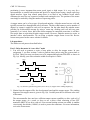
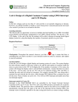
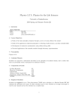
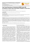
Dept. of Electrical and Computer Engineering
CME 331 - Microprocessor Embedded System
Khan A. Wahid
Last updated: October 6, 2014
Lab 3: Design of a stepper motor controller
Safety:
In this lab, voltages used are less than 15 volts and this is not normally dangerous to humans.
However, you should assemble or modify a circuit when power is disconnected and do not touch
a live circuit if you have a cut or break in the skin.
Learning outcome:
This lab provides an opportunity to work with an ARM CortexM4F microcontroller (MCU)
using the Stellaris® LM4F120 LaunchPad that has a Cortex LM4F120H5QR microprocessor.
Upon completion of this lab, the students will be able to:
(a) Learn basic operation of a stepper motor and design a controller circuit to drive the motor
(b) Write C code using Keil uVision to drive the stepper motor in two different directions at
different speeds, and calculate and display motor speed in rpm on the 7-segment display
(c) Learn how to use the system timer (SysTick) and header file in your design
Required hardware:
Materials
Equipment
Diodes (1N4001) - 4
Stellaris LM4F120 LaunchPad
MOSFET (IRL2703) - 4
Stepper motor (RB-Soy-03)
Resistors (330 ohm) – 4
12-V supply
7-segment display board
Checkpoints: Throughout this manual, wherever you find a
sign, it means that there is
something that you need to (a) show to your instructor and/or (b) observe, measure, and explain
in your lab notebook.
Lab description:
In this experiment, we will use a 200 steps/revolution stepper motor. With this rating, the motor
will provide a smooth spinning and each new set of step pulses will cause the motor to rotate by
1.8°. You will use software generated step pulses to drive the motor. All three modes of
operation – wave drive, full-step, and half-step drive – will be tested. You will later modify your
code to control the speed and direction of the motor. Two switches will be used to start/stop the
motor and control the spinning direction (CW/CCW). The speed in rpm (in decimal) will be
displayed on the 7-segment board.
Stepper motor fundamentals:
Stepper motors are used when precise control of movement is needed. They are used in printers
and scanners to move paper or scan heads, in disk drives to move read/write head, in high
precision robotics to move robot’s arms or legs, etc. In these applications, precise control of
CME 331 Laboratory
2
positioning is more important than motor speed (rpm) or high torque. It is very easy for a
microcontroller to control both position and speed of a stepper motor using a simple open loop
digital interface. Open loop control means there is no need of any feedback circuit which
eliminates the need for any expensive feedback and sensing devices. The position of the motor
can simply be tracked by using the number of input step pulses.
A stepper motor can be of two types: bi-polar and unipolar. A bipolar motor has two coils and
typically current flows through both coils at all times. The drive shaft rotates a precise number of
degrees as current is applied to each coil in sequence. On the other hand, the unipolar motor
provides for bi-directional currents by using a center tap, dividing each coil into two parts
(generally 5 or 6 wires). Since, half of the electro-magnets are energized at one time, it will have
less torque than an equivalent bi-polar stepper motor. However, unipolar motors are easier to
interface with a microcontroller. We are using a unipolar stepper motor in our lab. Review
lecture notes posted on the course website for details.
Lab procedure:
The lab has several parts as described below:
Part 1: Drive the motor in “wave drive” mode
1. You will need to generate a series of step pulses to drive the stepper motor. In your
assignment 2, you have written C-code to generate these pulses using the system timer or
SysTick. These four step waveforms are to be outputted through pins PD0-PD3 as shown in
Fig. 1(a). Modify your code so that the width of each pulse is 3msec.
3 msec
PD0
PD1
PD2
PD3
(a)
(b)
Fig. 1 (a) Software generated step pulses (wave drive); (b) stepper motor winding diagram [5]
2. Obtain from the support office the development board and the stepper motor. The winding
diagram of the stepper motor is given in Fig. 1(b). Carefully note the six different color wires
of the motor.
The microcontroller does not have sufficient output current capability to drive each coil of
the stepper motor. As a result, we have to use a driver circuit consisting of four FET
transistors (IRF2703) to drive each coil. Four current limiting resistors are added. A snubber
circuit using four diodes (1N4001) is used to protect the transistors. For more information,
review the lecture notes.
CME 331 Laboratory
3
The motor driver circuit is already built in the development board. Consult the schematics of
the development posted on the course website. The connection diagram of the lab and the
driver circuit is given in Fig. 2.
12V
White
Yellow
Red
M
1N4001
LM4F120
LaunchPad
Black
PD0
Green
Blue
CW / CCW
SW2
PD1
PF0
PD2
start / stop
IRL2703
SW1
PD3
PF4
330
GND
PD3
330
PD2
330
PD1
330
PD0
Fig. 2 Connection diagram
3. Now, connect the stepper motor with the motor interface on the development board. Turn on
the 12V power supply. Download your code to the LaunchPad and the motor should spin
counter-clockwise (CCW). The experimental setup is shown in Fig. 3.
CAUTION: You should take extra caution when handling a motor and 12V supply. Always
turn on the 12V power supply to the motor last. Limit the current to 1-2A. Static charges may
damage the MOSFET; so, while you work on your code and the LaunchPad is idle or off,
you should turn off the 12V supply. Check the temperature of the MOSFET and the motor
regularly. Slight heat is generated in them, but excessive heat is an indication of abnormal
operation or miss-handling. In such case, turn off the power supply and ask for help.
Fig. 3 Experimental setup
CME 331 Laboratory
4
4. Now, modify you C-code to vary the speed of the motor. It may be achieved by varying the
width of the pulses. Observe the operation of the motor at variable speeds.
5. Modify your C-code so that the motor changes the direction (clock-wise). Observe the motor
spin in CW direction.
6.
Now, modify your C-code to spin the motor by exactly 360o (i.e., one complete
revolution). You will need it later in the lab when you calculate the rpm. Show the operation
of the motor to your instructor and demonstrate how motor speed and direction can be varied.
Part 2: Add header file and switches to control the motor
7. In this part, you will add two switches: one will turn on and off the motor (i.e., works as
push-on and push-off switch); the other will control the spin direction (i.e., push-CW and
push-CCW). You will use the two on-board switches (SW1 and SW2). However, these push
button switches are single-pole single-throw, so you will need to use software techniques to
accomplish the task. Review the lecture notes for more details on this topic.
8. Since you will use Port F now and ports A and B later in part 3, it is a good time to start
using a header file that contains all port definitions. Download the header file
(cme331_LM4F120.h) from the course website. It contains all GPIO definitions and some
important control registers that you may need in this course and other labs. As a result, from
now on, you can use this file in all your labs. In that case, you do not need to include any port
related definitions in your main C-code; simply include the header file in your code.
Unlocking SW2 (PF0): From earlier labs, you have learnt how to configure Port F to use
SW1. However, SW2 is by default locked internally inside the microcontroller as it is a nonmaskable interrupt (NMI) (p.213, section 5.2.3.1 [2]). A special 2-step procedure is required
to unlock it. As NMI pin, the Alternate Function Select, Pull-Up Resistor, Pull-Down
Resistor, and Digital Enable are all locked for PF0 until a value of 0x4C4F434B is written to
the Port F GPIO Lock Register (GPIO_PORTF_LOCK, p.637). After Port F is unlocked, bit
0 of the Port F GPIO Commit Register (GPIO_PORTF_CR, p.638) must be set to ‘1’ to
allow access to PF0’s four control registers.
In LM4F, this protection is currently implemented only on the NMI and JTAG/SWD pins
(PD7, PF0 and PC[3:0]); all other bits/pins in the GPIO_PORTX_CR registers are hardwired
to ‘1’ (i.e., no change is possible), ensuring that it is always possible to commit new values to
the GPIOAFSEL, GPIOPUR, GPIOPDR, or GPIODEN register. Requiring this procedure
makes it unlikely to accidentally re-configure the JTAG and NMI pins as GPIO, which can
lock the debugger out of the processor and make it permanently unable to be debugged or reprogrammed [3].
9.
Modify your C-code to unlock SW2 and implement the on/off and CW/CCW features
to the motor controller. While modifying you code, it highly recommended drawing a flow
graph (or flow chart) that shows the flow of your algorithm or steps. It will help you better
debug the code. Show the operation to the instructor.
CME 331 Laboratory
5
Part 3: Drive the motor in “full-step” and “half-step” modes
10. Modify your C-code to generate the full-step pulses to drive the motor. In this case, two
phases are always on and the motor will run at full rated torque. Compile and download your
code, and observe the motor performance (smoothness, torque, speed, etc.).
11. Modify your C-code to generate the half-step pulses to drive the motor. This drive mode
alternates between two phases on and a single phase on. Compile and download your code,
and observe the motor performance.
12.
Show both drive modes to your instructor.
Part 4: [Optional] Calculate and display motor speed in rpm on 7-segment display
13. Choose any drive mode. Write software to calculate the motor speed in revolution per minute
or rpm. To achieve it, you need to know how long it takes to perform one complete
revolution (see Step 6). Use the 7-segment display to display the rpm in decimal.
While displaying the rpm on 7-segment, you will need to convert it into decimal. There are
many ways you can convert a value to decimal for display purpose, such as, divide the
number by 10 and take the quotient and remainder; or convert the number to BCD (binary
coded decimal). Use any technique of your choice. Some instructions will be given in the lab.
14.
Obtain an optical tachometer and measure the motor speed. Take at least three readings.
Compare the readings with your calculation. Show your design to the instructor.
Part 5: Answer the following questions in your lab notebook
15. From the lab experiments, comment on the three drive modes and compare the motor
performance: full-step vs. half-step vs. wave drive. Which mode will offer a smoother
operation? Which mode will give you the highest torque? Is there any other way you could
drive the stepper motor? Give one example of each driver mode.
16. [Optional] Which rpm reading is more accurate (optical tachometer vs. software)? Calculate
the average error (%) in the reading of the motor speed.
17. Explain in your notebook the operation of the driver circuit (given in Fig. 2)? Why are diodes
used in backward? What else could have been used instead of the FET transistor?
References:
1.
2.
3.
4.
5.
CME331 class website: https://www.engr.usask.ca/classes/CME/331
LM4F120H5QR Datasheet (Aug 29, 2012): http://www.ti.com/lit/gpn/lm4f120h5qr
Stellaris® LM4F120 LaunchPad User Manual (SPMU289A–Revised December 2012):
http://www.ti.com/tool/sw-ek-lm4f120xl
Lab dev board schematics:
https://www.engr.usask.ca/classes/CME/331/WebNotes_2014/Drawing_dev_board.jpg
http://www.robotshop.com/ProductInfo.aspx?pc=RB-Soy-03
CME 331 Laboratory
6
Appendix A: LaunchPad interface
J1
J3
J4
J2
3.3V
VBUS
PF2
GND
PB5
GND
PF3
PB2
PB0
PD0
PB3
PE0
PB1
PD1
PC4
PF0
PE4
PD2
PC5
RST
PE5
PD3
PC6
PB7
PB4
PE1
PC7
PB6
PA5
PE2
PD6
PA4
PA6
PE3
PD7
PA3
PA7
PF1
PF4
PA2
Fig. I Header pins on the LaunchPad (EK-LM4F120XL / EK-TM4C123GXL)
Virtual Serial Port
(UART)
USB
(device
only)
PA1
PA0
R29 0E
+5V
R25 0E
+5V (VBUS)
LM4F120
or
TM4C123
LEDS ARE
IN SINGLE
PACKAGE
RED
R10 0E
GREEN
330E
PB1
PD5
PD4
PB0
R12 0E
PF1
PD0
R9 0E
BLUE
330E
PB6
R11 0E
PD1
PB7
PF2
SW1
330E
PF4
R13 0E
R2 0E
PF3
SW2
PF0
R1 0E
(LOCKED)
Fig. II Connection diagram of on-board LEDs and switches in the LaunchPad
END