1
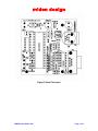
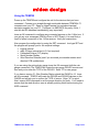
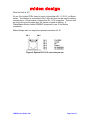
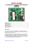
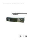
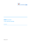
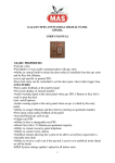
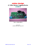
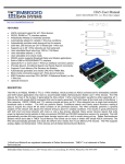
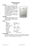
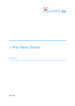
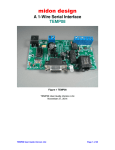
midon design A Temperature Logging Serial Interface TEMP05 TEMP05 User Guide VH6 December 29, 2004 TEMP05 User Guide VH6 Page 1 of 1 midon design Table of Contents Table of Contents..................................................................................................2 Introduction ...........................................................................................................3 Using the TEMP05................................................................................................6 TEMP05 Commands.............................................................................................7 Using the SET Command..................................................................................8 The DIS Display Output.....................................................................................8 DIS output explanations ....................................................................................9 MEM and EEP Commands .............................................................................10 TEMP05 Schematic ............................................................................................11 Software Change History ....................................................................................12 Upgrading The Software .....................................................................................12 Summary ............................................................................................................15 Legal Disclaimer .................................................................................................15 TEMP05 User Guide VH6 Page 2 of 2 midon design Introduction Thank you for your purchase of the TEMP05 assembled unit. TEMP05 is a stand-alone 1-Wire interface providing standard serial commands to control the Dallas/Maxim 1-Wire bus and the devices used on it. The TEMP05 has the following features: • support for multiple DS2438-based Humidity Sensors, including, of course, the Midon Design MD3020E sensor. • support for DS2438 based Barometric Sensors (note: we do not support the AAG Pressure Sensor) • support for DS2438 general purpose sensors for analog voltage input • support for DS18S20, DS18S20-PAR, DS18B20, DS1822, DS1920 temperature sensors as well as temperature reading from any DS2438 • simultaneous temperature conversion for temperature sensors if all are equipped with local powering. This results in faster outputs. Note that a DS2438 on the 1-Wire bus will prevent this feature from being enabled. • support for the DS2450 based Weather Station (wind speed and direction) - only one allowed. • support for multiple DS2423 based rain gauges • support for multiple DS2423 general purpose counters (for use with Lightning sensors and other types of counter inputs) • support for DS2405, DS2406 or DS2407 inputs and outputs. Use the DS2405/6/7 to read alarm or PIR contacts. They are continuously polled (if 1-Wire readings are not being displayed) and TEMP05 will display a notice if the input changes state. If the state changes during a display period, the new state will be flagged following the display period. The DS2405/6/7 can also be used to actuate relays or LED's in output mode. • supports detection of DS2401 or DS1990 1-Wire serial numbers • jumper-less provisioning - all configuration settings stored in non-volatile memory • up to 60 sensors supported • simple instruction set • easy to delete sensors, if they are no longer required, using the DEL command • same access to the RELAY05 as the original TEMP05 • 1-Wire bus errors are flagged when they occur • Support for software serial flow control (Control-S, Control-Q) TEMP05 User Guide VH6 Page 3 of 3 • midon design continuous poll for ALL sensors - TEMP05 will notify you when any sensor is connected or disconnected, providing that they have been INI'd. Very useful for locating intermittent 1-Wire bus problems or for real-time polling of contact sensors. To complete this project, you will need to connect a 12 to 16 Volt (AC or DC) transformer to the terminal J1 (see Figure 2 for location of J1). If you are using the auxiliary RELAY05 unit with TEMP05, choose a transformer that is as close to 12 Volts as possible and that provides at least 0.7 Amperes. Otherwise, any 12 to 16 Volt adapter capable of at least 100mA will do. If you are using a sensor network of DS1820's for temperature readings, connect them now to connector J2. Only 2 pins of each DS18S20 need be connected, however a connection is required between the VDD and GND pins of the DS18S20 if you are using parasitic power. See Figure's 1 and 3 for connections. On Rev G or higher PCB’s, a third terminal on J2 is provided for distributing +5V to the 1-wire bus. You should use this to supply so-called local power to any 1Wire devices that require it. . Figure 1 DS18S20 Pin-out (front view) TEMP05 User Guide VH6 Page 4 of 4 midon design Figure 2 Parts Placement TEMP05 User Guide VH6 Page 5 of 5 midon design Using the TEMP05 Power up the TEMP05 and configure the unit for the devices that you have connected. Connect up a straight-through serial cable between TEMP05's P1 connector and your PC. Open up HyperTerminal (or equivalent terminal emulator program) on your PC. Configure it to 9600 BPS, No parity, 8 bits, 1 start bit and NO hardware handshaking (very important!). Issue an INI command to configure any connected sensors on the 1-Wire bus. If you get any error messages (OW Bus Error or WDT Reset), it is most likely a result of a bad connection to the 1-Wire sensors. Verify the connections. Now program the configuration by using the SET command. Just type SET and the program will prompt you for the required settings: • logging interval • relay off timer interval (set to 0 if not required) • Fahrenheit/Celsius (F/C) display • Serial Number Display • Wind Direction Reverse (use if you mounted your weather station wind direction PCB upside down) If you are using the optional rain gauge issue the INI command (with the rain gauge connected). The TEMP05 will locate the rain gauge DS2423 counter and then ask you to enter the TYPE of the DS2423. Enter “R” for rain gauge. If you have a version 3 1-Wire Weather Station attach the OWWS to J2. Issue an INI command. TEMP05 will locate the DS2450 and DS2423 devices on the OWWS and will ask you to confirm the TYPE of sensor. Enter “W” for wind. Next, issue a NOR command to set the proper direction for North. You’ll need to ensure that the wind direction vane is actually pointing North before issuing the NOR command. TEMP05 User Guide VH6 Page 6 of 6 midon design TEMP05 Commands Table 1. Commands Available Command DEB RLB Description Toggle the debug mode on or off. Debug mode on will produce massive amounts of useless (to you) data. Only use under direction from Midon Design Display serial numbers of all configured 1-Wire devices Display and change specific EEPROM memory locations Erase the EEPROM Display a list of available commands Search for a list of available DS18S20's and rain gauge Display and change specific memory locations Turn Off a DS2405,DS2406, or DS2407 1-Wire switch Turn On a DS2405,DS2406, or DS2407 1-Wire switch Actuate all relays at once RLY Actuate a specific relay DIS EEP ERA HLP INI MEM OFA ONA RST SET TMP TS2 TYP VER ZZZ Reset any DS2423 counter Configure the parameters Display readings of all connected sensors in either verbose (includes serial numbers) or non-verbose manner A debug command that continuously polls the wind direction sensor and displays it. Exit the poll by entering any character. Manual set a device TYPe. Used only for DS2438 and DS2423 devices Displays the current version of the software loaded Soft reset the unit TEMP05 User Guide VH6 Syntax DEB DIS EEP <start location> ERA HLP INI MEM <start location> OFA<sensorid> ONA<sensorid> RLB x where x = an 8 bit binary number representing all relays. The MSB is relays 8 and a 1 turns on a relay. RLY <relay number> <on|off> where <relay number> = 1 to 8 or A for All. RLY S (displays status of all relays) RST<sensorid> SET TMP TS2 TYP<sensorid> VER ZZZ Page 7 of 7 midon design Using the SET Command The SET command has multiple parameters. Update Interval determines the time between sensor readings. Set to 0 to stop polling (Note: this is only available in versions 5.11 and higher). Enter the time in decimal minutes. Relay Off Timer determines how much time to wait between turning on ANY relay and turning them ALL off. Enter the time in decimal minutes. Enter 0 to disable this function. F or C Display determines how temperature readings are displayed. Enter F for Fahrenheit or C for Celsius. Serial # Display - set to Yes if you want TEMP05 to display the 1-wire ID of all sensors. Wind Dirn Reverse - set normally to N. Set this to Y if you accidentally installed the wind direction PCB upside down in your weather station OR if you want to display wind direction as the FROM direction instead of the TO direction. The DIS Display Output Sample DIS Output 01 6412340000567810 DS1820 OK 02 5587650000432122 DS1822 OK 03 3355540000447728 DS18B2 OK 04 8811220000334410 DS1820 OK 05 1288770000665526 DS2438 OK H 06 2133440000556626 DS2438 OK B 07 1299880000776626 DS2438 OK V 08 AAFEDC0000BA1226 DS2438 OK H 09 1AABCD0000EF011D DS2423 OK W 10 016543000021AB1D DS2423 OK R 11 541A2B00003C4D1D DS2423 OK L 12 FF66FF00FFFFFFFF ??? NG 13 9F00000016A2DE05 DS2405 OK Update interval = 02 minutes Temp display = F Serial # display = On Wind dirn reverse = Off Relay off timer= 00 minutes Some temp sensors Parasitic powered Qty of DS1820 = 2 Qty of DS1822 = 1 Qty of DS18B2 = 1 Qty of DS2438 = 4 TEMP05 User Guide VH6 Page 8 of 8 midon design DIS output explanations Sensor numbers do not necessarily match up with the output from the regular sensor output readings. This is intentional. The sensor numbers in the DIS output are the memory locator and are used by the DEL, RST, ONA, OFA and TYP commands. The sensor numbers in the scan output are sequential numbers for each type of sensor. An OK will be displayed following the sensor type to indicate that the Cyclic Redundancy Counter (CRC) checksum of the sensor's serial number is good. If the serial number has a bad CRC, an NG will be displayed. The checksum is validated during the output of the sensor display. Letters following the DS2423 and DS2438 indicate the TYPe of sensor equipped. This is a manual input and will be set following first discovery of the sensor via the INI command, and also following a power-up of the TEMP05 for the DS2423 sensors that do not have built-in battery backup. The letters designate the sensor type per the following table. Sensor Types Designation Description OW Device H Humidity Sensor DS2438 B Barometric Sensor DS2438 L Lightning Sensor DS2423 W Wind Speed Sensor DS2423 R Rain Sensor DS2423 V Voltage Sensor DS2438 Following a display of the sensors installed, the output of the DIS display then shows the TEMP05 settings that you entered via the SET command. The DEBug mode is then shown. To turn on or off the DEBug mode, use the DEB command. Following that, the DIS display then checks to see if all temperature sensors parasitically or locally powered. If ANY temperature sensor connected to the Wire bus is set to parasitic mode, then the display will show "some sensors parasitic powered". The same display will result of ANY DS2438 devices are present on the 1-Wire bus. Following that display the DIS output proceeds to show how many temperature sensors are installed, by type. The DS18B2 type indicates a DS18B20 sensor. The DS1820 type is valid for DS1820, DS18S20 and DS1920 sensors. TEMP05 User Guide VH6 Page 9 of 9 midon design MEM and EEP Commands The MEM and EEP commands can be used for debugging, but we don’t recommend this unless you know what the memory locations are used for. TEMP05 User Guide VH6 Page 10 of 10 midon design TEMP05 Schematic P1 U4 5 9 4 8 3 7 2 6 1 5 18 4 19 11 15 16 10 DB9 To User Terminal T1OUT T2OUT R1IN R2IN C2+ C2+ C2C2- MAX233 T1IN T2IN R1OUT R2OUT C1+ C1VVV+ 2 1 3 20 8 13 12 17 14 D2 LED Bipolar J3 1 2 3 4 5 6 7 8 9 10 11 12 13 14 15 16 U1 C3 11 10 9 8 7 6 5 4 22pFd R2 10M 39 38 Y1 4.0MHz 37 R3A 16 pin DIP C2 22pFd C R3A +5V 29 34 36 2 1 10K C 10K J1 1 2 + +5V 40 PA0 PA1 PA2 PA3 PA4 PA5 PA6 PA7 PB0 PB1 PB2 PB3 PB4 PB5 PB6 PB7 OSC1 OSC2 PC0 PC1 PC2 PC3 PC4 PC5 PC6 PC7 TCAP PD0 PD5 PD7 IRQ RST VDD C1 10uFd PD1 PD4 PD2 PD3 TCMP 12 13 14 15 16 17 18 19 LED1 LED2 +5V R5 1.5K CS1 One-Wire Bus 1 2 3 4 5 6 7 8 CLK DO DI D4 J2 J4 1 2 3 1N4148 CON3 +5V U2 1 2 3 4 CON8 CS CLK Test DI ORG DO 7 6 93C56 35 68HC705C8 Term 1N4148 DATA 28 27 26 25 24 23 22 21 30 33 31 32 D9 Power & Ground Table 2 - 1 + C5 1000uFd IN U4 VCC=7 GND=6,9 +5V Out U2 VCC=8 GND=5 3 + C4 100uFd C6 0.1uFd 2 3 BRIDGE U3 LM78L05 C C C C C C C + 4 GND 1 U1 Vcc =40 Gnd=20 D1 Title TEMP05 - One Wire Thermometer Sy stem Size A Date: Document Number SD000101 Rev 04 Sunday , December 09, 2001 Sheet 2 Figure 3 TEMP05 Schematic Diagram (REV G and higher) TEMP05 User Guide VH6 Page 11 of 11 of 2 midon design Software Change History Version 5.13 Date 5/25/03 5.11 2/1/03 5.10 1/6/03 5.00 12/13/02 4.25 2/11/02 4.24 4.23 4.22 2/10/02 12/15/01 10/26/01 4.21 9/1/2001 4.20 4.19 4.18 4.17 8/30/2001 8/10/2001 7/22/2001 7/9/2001 4.16 4.15 4.14 4.13 4.12 7/7/2001 6/16/2001 5/27/2001 5/12/2001 3/20/2001 Major Changes from Previous Loads Fixed Relay delay issues when relay command issued in the middle of another commands output. Added timeout for inactive inputs (to avoid locking up TEMP05 if a power failure occurs). Added On/Off input to the DEB command. Added a >100% indicator for humidity readings. Fixed a bug where a DIS display in the middle of a sensor poll would disrupt the sensor ID numbers. Fixed a bug where Polling Interval =0 would still cause a 1 minute poll. Added capability of working with both 93C56 and 93C66 EEPROMs. Many new features added. See the introduction of this manual for details. Added 93C66 EEPROM capabilities with an auto-check on power up for EEPROM type. Minor tweaks to code size Added parasitic check and display for DIS and QTY commands. Fixed HUM command to ensure continuation of humidity readings even after an error on one reading. Added support for DS18B20 and DS1822 temperature sensors. Added check on OW bus for shorts or reversed sensors. QTY command now counts DS18S20, DS18B20 and DS1822 sensors separately. Changed sensor numbering to start at 1 instead of zero. Fixed bug in 4.19 - will only read 1 humidity sensor. Code compaction only Added REV and RLT commands. Added support for V3 OWWS by AAG. Added NOR command to set true north on OWWS. Added RLB command to control all Relays at once. Beta version of DS2450 based weather station support Added QTY command Added capability of connecting multiple humidity sensors Added CRC command Added humidity sensor capability and increased temperature display precision Upgrading The Software Upgrading the software on TEMP05 requires a hardware change of the processor chip. Here is how to upgrade the chip. 1. Remove Power from the TEMP05. 2. Using a small screw-driver, or similar tool, gently remove the 68HC705C8 micro-controller by inserting the screw-driver between the micro-controller and the DIP socket that it is inserted to. TEMP05 User Guide VH6 Page 12 of 12 midon design 3. Making sure that you are grounded, or adequately static free, insert the new micro-controller into the socket. Care should be taken to observe correct polarity. The end of the micro-controller with a small notch, or a dot in the left-corner, should be positioned to be close to the 10uFd capacitor as per Figure 2. 4. Make sure that all micro-controller pins are seated in the socket. Check for pins that may have bent inwards. 5. Restore power to the TEMP05. 6. Enjoy your new features. TEMP05 User Guide VH6 Page 13 of 13 midon design What the heck is J6? On rev G or higher PCB’s, there is a spot for inserting a RJ-11, RJ-12, or iButton holder. This location is connected to the 1-Wire bus and can be used for adding connectivity to 1-Wire busses configured for RJ-11/12 connection. This can also be used, but not at the same time, as a place to insert an iButton. A Dallas/Maxim iButton holder DS9094F is required to use J6 for iButton connection. Midon Design does not supply the optional connectors for J6. Figure 4 Optional RJ11/12 connector pin-out TEMP05 User Guide VH6 Page 14 of 14 midon design Summary Your comments are appreciated. If you would like to submit feature requests or product recommendations, please e-mail us. Please also check the Frequently Asked Questions link on the TEMP05 web page. Legal Disclaimer YOUR USE OF THIS PRODUCT IS AT YOUR OWN RISK. YOU ASSUME FULL RESPONSIBILITY AND RISK OF LOSS RESULTING FROM THE USE OF THIS PRODUCT. MIDON DESIGN WILL NOT BE LIABLE FOR ANY DIRECT, SPECIAL, INDIRECT, INCIDENTAL, CONSEQUENTIAL OR PUNITIVE DAMAGES OR ANY OTHER DAMAGES WHATSOEVER, WHETHER IN AN ACTION BASED UPON A STATUTE, CONTRACT, TORT (INCLUDING, WITHOUT LIMITATION NEGLIGENCE) OR OTHERWISE, RELATING TO THE USE OF THIS PRODUCT. Thank you! [email protected] © Copyright 2001-2005 Midon Design. All rights reserved. No part of this document may be reproduced, recorded, transmitted or distributed in any form or by any means without the written consent of Midon Design. 1-Wire is a trademark of Dallas Semiconductor (now Maxim) End of Document TEMP05 User Guide VH6 Page 15 of 15