1
IS620P User Manual
Preface
Preface
Thank you for purchasing the IS620P series servo drive developed by Inovance Technology
Co., Ltd.
The IS620P series is a high-performance AC servo drive for small and medium power
applications. The IS620P series ranges from 100 W to 7.5 kW. It supports the Modbus
communication protocol with RS232/RS485 communication port, and thus allowing networking
of multiple IS620P drives controlled by a host PC. The IS620P is easy to use with the functions
of rigid table setting, inertia identification and oscillation suppression. It works quietly together
with Inovance ISMH series small/medium-inertia high-response servo motor configured with
20-bit incremental encoder. This servo drive is able to realize rapid and accurate position,
speed and torque control, and is applicable for such automation equipment as semiconductor
manufacturing equipment, chip mounter, PCB punching machine, transport machinery, food
processing machinery, machine tool and conveying machinery.
This manual describes the correct use of the IS620P series servo drive, including safety
information, mechanical and electrical installation, commissioning and maintenance. Read
and understand this manual before use. Contact our customer service center if you have any
question during the use.
The instructions are subject to change, without notice, due to product upgrade, specification
modification as well as efforts to increase the accuracy and convenience of the manual.
If you are an equipment manufacturer, forward this manual to the end user.
-1-
Preface
IS620P User Manual
■■ Product Checking
Upon unpacking, check the items described in the following table.
Check Item
Whether the product that you
received is consistent with your
order
Description
The box contains the IS620P servo drive and user manual.
Check the models of the servo drive and servo motor on the
nameplate.
Check the overall appearance of the product. If there is
Whether the servo drive is damaged
any omission or damage, contact Inovance or your supplier
during transportation
immediately.
Whether the rotating shaft of the
servo motor rotates smoothly
If the shaft of the servo motor can be rotated manually, it is
normal. The servo motor configured with a brake, however,
cannot be rotated manually.
Notes
•• This drive is a general industrial automation product, and is not designed for use in machinery or
system on which lives depend.
•• Wiring, operation, maintenance and inspection of the product can only be performed by qualified
persons.
•• When selecting the tightening torque of the screw, consider the strength of the screw and
material of the installation part. Select a proper value while the screw is fixed solidly and the
installation part will not be damaged.
•• Install an appropriate safety device when this product is to be used on machinery which may
cause severe accidents or loss due to trips of the product.
•• Contact Inovance when this product is to be used on special applications such as atomic energy
control, aerospace equipment, transport equipment, medical apparatus, safety devices and
other equipment that require high cleanliness.
•• Although this product has passed all QC testing, it may react unexpectedly due to trips arising
from ambient noise, static interference, input power supply, wiring, optional parts, and etc. Take
mechanical safety measures into fully consideration to ensure safety in the applications where
all possible actions of the equipment occur.
•• When the motor shaft runs without being grounded, based on the actual mechanical and
installation conditions, the motor bearing may suffer from electric corrosion or large noise.
•• Trips of this product may cause rising smoke. Pay special attention to such condition when the
product is to be used in purification workshop and environment alike.
•• Chip resistor disconnection or poor contact condition may occur due to sulfuration reaction if the
product is to be used in an environment with high-density sulphur or sulfuretted gas.
•• Verify that the input voltage of the drive is within the allowable range. If the input voltage is much
larger than the rated value, internal components may be damaged, thus resulting in smoke or
even a fire.
•• End users decide whether the servo drive matches the structure, size, service life, features,
specification change of the equipment (to which the servo drive is to be installed) and its parts,
and whether complies with local codes and regulations.
•• Never use the drive beyond the technical specifications.
•• This product is subject to change of certain components for the purpose of continuous
improvement of the product.
-2-
Contents
Preface���������������������������������������������������������������������������������������������������������������������� 1
Chapter 1 Servo System Selection��������������������������������������������������������������������������� 6
1.1 Designation Rules of the Servo Motor and Servo Drive������������������������������������������������������� 8
1.2 Servo System Configuration������������������������������������������������������������������������������������������������� 9
1.3 Adapted Cables.................................................................................................................�� 10
1.4 Regen Resistor Specifications������������������������������������������������������������������������������������������� 15
Chapter 2 Mounting Dimensions of Servo System�������������������������������������������������� 18
2.1 Installation of the Servo Motor�������������������������������������������������������������������������������������������� 18
2.2 Installation of the Servo Drive�������������������������������������������������������������������������������������������� 20
2.3 Mounting Dimensions of the Servo Motor�������������������������������������������������������������������������� 22
2.4 Overall Dimensions of the Servo Drive������������������������������������������������������������������������������ 36
Chapter 3 Wiring of Servo System�������������������������������������������������������������������������� 38
3.1 Servo Drive Main Circuit Wiring........................................................................................�� 39
3.2 Connecting Servo Motor Encoder Signals������������������������������������������������������������������������� 48
3.3 Connecting Control Signal Terminals................................................................................�� 50
3.4 Communication Signal Wiring�������������������������������������������������������������������������������������������� 64
3.5 Analog Monitoring Signal Wiring���������������������������������������������������������������������������������������� 67
3.6 Anti-interference Measures for Electrical Wiring���������������������������������������������������������������� 68
3.7 Precautions of Using Cables���������������������������������������������������������������������������������������������� 72
Chapter 4 Running and Commissioning������������������������������������������������������������������ 74
4.1 Use of the Position Control Mode��������������������������������������������������������������������������������������� 75
4.2 Use of the Speed Control Mode����������������������������������������������������������������������������������������� 83
4.3 Use of the Torque Control Mode����������������������������������������������������������������������������������������� 91
4.4 Check Before Running������������������������������������������������������������������������������������������������������� 99
4.5 Load Inertia Auto-tuning and Gain Adjustment����������������������������������������������������������������� 100
Chapter 5 Background Software��������������������������������������������������������������������������� 108
Chapter 6 Troubleshooting�������������������������������������������������������������������������������������110
6.1 During Startup������������������������������������������������������������������������������������������������������������������ 110
6.2 During Running���������������������������������������������������������������������������������������������������������������� 120
Chapter 7 Function Code Table����������������������������������������������������������������������������� 160
Group H00: Servo Motor Parameters������������������������������������������������������������������������������������� 161
Group H01: Servo Drive Parameters������������������������������������������������������������������������������������� 161
Group H02: Basic Control Parameters����������������������������������������������������������������������������������� 162
Group H03: Input Terminal Parameters���������������������������������������������������������������������������������� 165
Group H04: Output Terminal Parameters................................................................................168
Group H05: Position Control Parameters................................................................................170
Group H06: Speed Control Parameters��������������������������������������������������������������������������������� 175
Group H07: Torque Control Parameters��������������������������������������������������������������������������������� 177
Group H08: Gain Parameters������������������������������������������������������������������������������������������������� 179
Group H09: Self-adjusting Parameters���������������������������������������������������������������������������������� 181
Group H0A: Fault and Protection������������������������������������������������������������������������������������������� 184
Group H0B: Display Parameters�������������������������������������������������������������������������������������������� 186
Group H0C: Communication Parameters������������������������������������������������������������������������������� 188
Group H0D: Auxiliary Function Parameters��������������������������������������������������������������������������� 190
Group H0F: Full Closed-loop Parameters������������������������������������������������������������������������������ 191
Group H11: Multi-Position Function Parameters�������������������������������������������������������������������� 192
Group H12: Multi-Speed Function Parameters���������������������������������������������������������������������� 197
Group H17: VDI/VDO Parameters����������������������������������������������������������������������������������������� 203
Group H30: Servo Related Variables Read via Communication�������������������������������������������� 208
Group H31: Servo Related Variables Set via Communication................................................208
DI/DO Basic Functions����������������������������������������������������������������������������������������������������������� 209
Appendix: Version Change Record����������������������������������������������������������������������� 217
1
Servo System Selection
Chapter 1 Servo System Selection
IS620P User Manual
Chapter 1 Servo System Selection
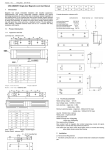
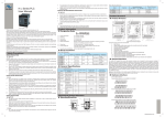
Figure 1-1 Servo drive composition
Name
Function
Connect to the measuring instrument (such as an oscilloscope ) to
facilitate viewing signal status when gains are adjusted.
CN5 analog monitoring
signal terminal
Display the running status and parameter setting of the servo system.
LED display
SET
MODE
5R 5
I S 6 2 0 P-S
Save and enter the next-level menu.
Shift the blinking digit to the left.
Hold down: Turn page when more
than 5 digits are displayed.
Decrease value of the blinking digit.
Operation buttons
Increase value of the blinking digit.
Switch function codes in turn.
Used to indicate that the bus voltage is in CHARGE status.
Indicator ON: Capacitors inside the servo drive still contain electricity
even if the main circuit power is OFF.
Thus, do not touch the power supply terminal when CHARGE indicator
is ON, to prevent electric shock.
CHARGE
bus voltage indicator
L1C/L2C control
circuit power input
terminals
IS6 20 P-S 5 R
Input control circuit power supply as per the rated voltage on the
nameplate.
R/S/T main circuit power
input terminals
Input main circuit power supply as per the rated voltage on the
nameplate.
5
C
N
3
L1C
L2C
P/
Used when multiple servo drives share the same DC bus.
servo drive bus terminals
C
N
4
P
P
P / D/C
braking resistor
connection terminals
U/V/W servo motor
connection terminals
PE grounding terminal
CN2 encoder connection
terminal
CN1
control terminal
P
P -D is shorted by default. Remove jumper between P -D when
P
connecting an external braking resistor, and connect the resistor
between P -C.
P
R
S
T
P+
C
N
1
D
C
U
Connect U, V and W phases of the servo motor.
V
W
C
N
2
Used as the grounding terminal of the power supply and motor.
Connect to the motor encoder.
Used for reference input signals and other I/O signals.
Connected in parallel inside the servo drive.
CN3/CN4
communication terminals Connect to RS232 or RS485 communication devices.
Note
For models (S1R6 and S2R8) using the single-phase power supply, the main circuit power input
terminals are L1 and L2. These models do not have the built-in regenerative braking resistor
(hereinafter shorted as "regen resistor"), and therefore terminal D is unavailable. If you need to
connect an external regen resistor, connect it between P and C.
-6-
IS620P User Manual
Chapter 1 Servo System Selection
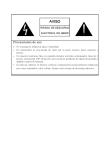
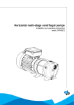
Figure 1-2 Wiring example of three-phase 220 V system
Power supply
Three-phase 220
VAC
IS620P-S5R
5
CN5
Servo drive analog monitoring cable
Molded-case circuit breaker (MCCB)
Cut off circuit if overcurrent occurs to
the protect power supply line.
Communication cable for
multi-drive parallel connection
Noise filter
Prevent external noise
from power supply line.
Servo drive to PC
communication cable
Electromagnetic contactor
Turn ON/OFF power of the servo
drive. Install a surge suppressor
when using this contactor.
Regen resistor
Connect a regen resistor
between P- C when the
bus voltage is insufficient.
CHARGE
L1C
L2C
R
S
T
Note 1
CN3
CN4
Servo drive to PLC
communication cable
-
CN1
U
V
W
CN2
P
D
C
Note 2
PE
Servo drive I/O cable
(prepared by user)
Servo motor
encoder cable
System ground
Brake power supply
24 VDC power supply, used
when the servo motor is
configured with brake.
24 VDC
Servo motor main
circuit cable
Electromagnetic contactor
The brake controls signal to turn
ON/OFF of the brake power
supply. Install a surge suppressor
when using this contactor.
••
The IS620P servo drive is directly connected to an industrial power supply, with no
isolation such as using a transformer. In this case, you need to connect a fuse or
molded-case circuit breaker (MCCB) on the input power supply to prevent cross electric
accidents in the servo system.
••
The IS620P servo drive has no built-in protective grounding circuit. Thus, connect a
residual-current circuit breaker (RCCB) against overload or short-circuit or a specialized
RCCB combined with the protective grounding.
••
Never use magnetic contactor for running or stopping the servo motor. Since motor is a
large inductance element, instantaneous medium voltage generated may damage the
contactor.
••
Pay attention to the power capacity when connecting an external power supply or 24
VDC, especially when the power supply is for powering up multiple drives or brakes.
Insufficient power supply will lead to lack of supply current, thus causing failure of the
drives or brakes. The brake shall be powered up by a 24 VDC power supply. For power
information, refer to the model of the motor.
-7-
Chapter 1 Servo System Selection
IS620P User Manual
Observe the following precautions during wiring:
Note 1: Remove the jumper between terminals P and D of the servo drive before connecting
a regen resistor.
Note 2: CN3 and CN4 are two same communication ports, which can be used at random.
Note 3: For the single-phase 220 V servo drive, the main circuit terminals are L1 and L2.
Never wire the reserved terminal.
1.1 Designation Rules of the Servo Motor and Servo Drive
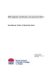
Figure 1-3 Designation rules of the servo motor
ISM H1-75B 30C B-U2 3 1 X
Series
Mark
ISM
Mark
ISM series servo motor
X
Mark
Feature
H
1
Low inertia, small capacity
2
Low inertia, medium capacity
3
Medium inertia, medium capacity
4
Low inertia, small capacity
Mark
x1
B
x 10
Mark
Rated Speed
(RPM)
x 100
D
x 1000
A
x1
x 10000
B
x 10
C
x 100
D
x 1000
E
x 10000
Example
75B: 750 W
15C: 1500 W
2nd generation motor
Mark
Encoder Type
1 letter + 1 digit
U
Example
15B: 150 RPM
30C: 3000 RPM
1
2500-PPR
incremental
2
20-bit bus type
Mark
Voltage Class
A
110 V
B
220 V
C
300 V
D
380 V
Brake, Gear, Oil Seal
None
1
With oil seal
2
With brake
4
With oil seal + brake
Mark
1 letter + 2 digits
C
E
Aviation plug
connection
Z
0
1 letter + 2 digits
A
Y
Mark
Rated
Power (W)
Customized Feature
Natural cooling
Shaft Connection
1
Optical shaft
2
Solid with key
3
Solid with key and
threaded hole
5
Solid with threaded
hole
Note
Models ending in –U231* and –U234 * are standard models. Prior ordering is required for nonstandard models.
ISMH2-20C/25C/30C/40C/50C are not configured with a brake now.
-8-
IS620P User Manual
Chapter 1 Servo System Selection
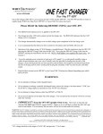
Figure 1-4 Designation rules of the servo drive
IS620 P
Mark
Series
IS620
Servo drive
Mark
Product Type
P
Pulse
Mark
Voltage Class
S
220 V
T
380 V
S 5R5 I - A
Mark
Customized Specification
A
16-bit high-accuracy analog
M
E-cam, synchronism of gate bridge
C
CANlink
CO
CANopen
Mark
Mounting Method
I
Substrate installation (standard)
Mark
1R1
1R6
2R8
3R5
5R4
5R 5
Rated output
current
1.1A
1.6A
2.8A
3.5A
5.4A
5.5A
7R6
8R4
012
017
021
026
7.6A
8.4A
12A
17A
21A
26A
Note
The models T017, T021, and T026 are under development.
1.2 Servo System Configuration
■■ 220 V
Servo Drive Model
(IS620P□□□□I)
Rated Max. Rated
Motor
Servo Motor Model
Drive
Speed Speed Power
Frame SingleThree(ISMH□-□□□□□□□-*****)
Size
(RPM) (RPM) (W)
Size phase 220 phase 220
VAC
VAC
5000
100
10B30CB
H1
(low inertia, 20B30CB
small
40B30CB
capacity)
75B30CB
40
S1R6
-
A
00002
60
S1R6
-
A
00002
60
S2R8
-
A
00003
A
00005
1000 H2
10C30CB
(low inertia,
1500 medium
15C30CB
capacity)
100
-
C
00006
100
-
C
00007
H3
(medium
inertia,
1300 medium
capacity)
85B15CB
130
-
C
00006
13C15CB
130
-
C
00007
200
3000
6000
5000
400
750
850
1500
3000
Drive SN
(H01-02)
80
S5R5
S7R6
S012
S7R6
S012
-9-
Chapter 1 Servo System Selection
IS620P User Manual
Servo Drive Model
(IS620P□□□□I)
Rated Max. Rated
Motor
Servo Motor Model
Drive
Speed Speed Power
Frame SingleThree(ISMH□-□□□□□□□-*****)
Size
(RPM) (RPM) (W)
Size phase 220 phase 220
VAC
VAC
400
3000
6000
750
H4
(medium
inertia,
small
capacity)
40B30CB
60
S2R8
-
A
Drive SN
(H01-02)
00003
A
75B30CB
80
S5R5
00005
■■ 380 V
Rated
Speed
(RPM)
Max.
Speed
(RPM)
6000
3000
5000
Servo Drive Model
Rated
Motor
(IS620P□□□□I)
Servo Motor Model
Power
Frame
(ISMH□-□□□□□□□-*****)
(W)
Size Three-phase 380
VAC
1000
100
T5R4
C
10002
1500
15C30CD
100
T5R4
C
10002
2000
100
T8R4
C
10003
100
T8R4
C
10003
3000
H2
20C30CD
(low inertia,
25C30CD
medium
30C30CD
capacity)
130
T012
C
10004
4000
40C30CD
130
T017
E
10005
5000
50C30CD
130
T017
E
10005
850
85B15CD
130
T3R5
C
10001
13C15CD
130
T5R4
C
10002
18C15CD
130
T8R4
C
10003
29C15CD
180
T012
C
10004
44C15CD
180
T017
E
10005
55C15CD
180
T021
E
10006
75C15CD
180
T026
E
10007
2500
1800
3000
Drive SN
(H01-02)
10C30CD
1300
1500
Drive
Size
2900
4400
5500
H3
(medium
inertia,
medium
capacity)
7500
1.3 Adapted Cables
Table 1-1 Adapted cables for servo motor without brake
Servo
Motor
Servo Motor Main Circuit Cable
Servo Motor Encoder Cable
L = 3.0 m L = 5.0 m L = 10.0 m L = 3.0 m L = 5.0 m L = 10.0 m
Connector Kit
CN1 terminal
ISMH1
ISMH4
S6-LS6-LS6-LM00-3.0 M00-5.0 M00-10.0
S6-LP00-3.0
S6-LP00-5.0
CN2 terminal
S6-LS6-C1 6-pin
P00-10.0
connector
9-pin
connector
- 10 -
IS620P User Manual
Servo
Motor
Chapter 1 Servo System Selection
Servo Motor Main Circuit Cable
Servo Motor Encoder Cable
L = 3.0 m L = 5.0 m L = 10.0 m L = 3.0 m L = 5.0 m L = 10.0 m
Connector Kit
CN1 terminal
ISMH1
ISMH4
X series
S5-LS5-LS5-LM03-3.0 M03-5.0 M03-10.0
S60-LP00-3.0
S60-LP00-5.0
CN2 terminal
S60-LS62-C1 4-pin
P00-10.0
connector
9-pin
connector
CN1 terminal
ISMH2
S6-LS6-LS6-LM11-3.0 M11-5.0 M11-10.0
S6-LP01-3.0
S6-LP01-5.0
CN2 terminal
S6-LS6-C2 20-18 aviation
P01-10.0 (elbow) plug (elbow)
20-29 aviation
plug (elbow)
CN1 terminal
ISMH3
S6-LS6-LS6S6-L(1.8 kW
M11-3.0 M11-5.0 L-M11-10.0 P01-3.0
and below)
S6-LP01-5.0
CN2 terminal
S6-LS6-C2 20-18 aviation
P01-10.0 (elbow) plug (elbow)
20-29 aviation
plug (elbow)
ISMH3
(2.9 kW)
S6-LS6-LS6-LM12-3.0 M12-5.0 M12-10.0
S6-LP01-3.0
S6-LP01-5.0
S6-LP01-10.0
ISMH3
(2.9 kW
above)
S6-LS6-LS6-LM22-3.0 M22-5.0 M22-10.0
S6-LP01-3.0
S6-LP01-5.0
S6-LP01-10.0
CN1 terminal
CN2 terminal
S6-C3 20-22 aviation
(elbow) plug (elbow)
20-29 aviation
plug (elbow)
Table 1-2 Adapted cables for servo motor with brake
Servo
Motor
Servo Motor Main Circuit Cable
Servo Motor Encoder Cable
L = 3.0 m L = 5.0 m L = 10.0 m L = 3.0 m L = 5.0 m L = 10.0 m
Connector Kit
CN1 terminal
ISMH1
ISMH4
S6-LB00-3.0
S6-LB00-5.0
S6-LB00-10.0
S6-LP00-3.0
CN2 terminal
S6-LS6-LS6-C1 6-pin connector
P00-5.0 P00-10.0
9-pin connector
- 11 -
Chapter 1 Servo System Selection
Servo
Motor
Servo Motor Main Circuit Cable
IS620P User Manual
Servo Motor Encoder Cable
L = 3.0 m L = 5.0 m L = 10.0 m L = 3.0 m L = 5.0 m L = 10.0 m
Connector Kit
CN1 terminal
ISMH1
ISMH4
X series
S5-LS5-LS5-LM03-3.0 M03-5.0 M03-10.0
S60-LP00-3.0
CN2 terminal
S60-L- S60-LS62-C1 4-pin connector
P00-5.0 P00-10.0
9-pin connector
CN1 terminal
ISMH2
S6-LB11-3.0
S6-LB11-5.0
S6-LB11-10.0
S6-LP01-3.0
CN2 terminal
S6-LS6-LS6-C2 20-18 aviation
P01-5.0 P01-10.0 (elbow) plug (elbow)
20-29 aviation
plug (elbow)
CN1 terminal
ISMH3
S6-L(1.8 kW
B11-3.0
and below)
S6-LB11-5.0
S6-LB11-10.0
S6-LP01-3.0
CN2 terminal
S6-LS6-LS6-C2 20-18 aviation
P01-5.0 P01-10.0 (elbow) plug (elbow)
20-29 aviation
plug (elbow)
ISMH3
(2.9 kW)
Prepared by the customer
S6-LP01-3.0
S6-LS6-LP01-5.0 P01-10.0
ISMH3
(2.9 kW
above)
Prepared by the customer
S6-LP01-3.0
S6-LS6-LP01-5.0 P01-10.0
CN1 terminal
CN2 terminal
S6-C3 20-22 aviation
(elbow) plug (elbow)
20-29 aviation
plug (elbow)
Note
The servo motor encoder cable package includes the CN1 connector.
Table 1-3 Communication cables
Cable Model
Description
S62-L-T00-3.0
Servo drive to PC communication cable
S62-L-T01-0.3
Communication cable for multi-drive parallel connection
S62-L-T02-2.0
Servo drive to PLC communication cable
S62-L-T03-0.0
Plug for matching terminal matching resistor for servo drive communication
- 12 -
IS620P User Manual
Chapter 1 Servo System Selection
Table 1-4 Physical appearance of cables for the servo motor and servo drive
Cable Name
Servo motor
main circuit
cable
Cable Model
Cable
Length
(mm)
S6-L-M00-3.0
3000
S6-L-M00-5.0
5000
S6-L-M00-10.0
10000
S5-L-M03-3.0
3000
S5-L-M03-5.0
5000
S5-L-M03-10.0
10000
S6-L-M11-3.0
3000
S6-L-M11-5.0
5000
S6-L-M11-10.0
10000
S6-L-M12-3.0
3000
S6-L-M12-5.0
5000
S6-L-M12-10.0
10000
S6-L-M22-3.0
3000
S6-L-M22-5.0
5000
S6-L-M22-10.0
10000
S6-L-B00-3.0
3000
S6-L-B00-5.0
5000
S6-L-B00-10.0
10000
S6-L-B11-3.0
3000
S6-L-B11-5.0
5000
Cable Appearance
30 mm
100±5 mm
25±5 mm
50 mm
50 mm
50 mm
L±30 mm
L±30 mm
L±30 mm
200±10 mm
L±20 mm
130 mm
10000
- 13 -
100±5 mm
L±30 mm
30 mm
200 mm
S6-L-B11-10.0
100±10 mm
L±20 mm
L±30 mm
Chapter 1 Servo System Selection
Cable Name
Cable Model
S6-L-P00-3.0
IS620P User Manual
Cable
Length
(mm)
Cable Appearance
3000
DB44 plug
S6-L-P00-5.0
5000
Note: DB44 is an attached plug, used to connect the CN1
terminal.
S6-L-P00-10.0
10000
L±15 mm
S60-L-P00-3.0
3000
DB44 plug
Servo motor
encoder cable
S60-L-P00-5.0
5000
Note: DB44 is an attached plug, used to connect the CN1
terminal.
S60-L-P00-10.0 10000
L±15 mm
S6-L-P01-3.0
3000
DB44 plug
S6-L-P01-5.0
5000
Note: DB44 is an attached plug, used to connect the CN1
terminal.
S6-L-P01-10.0
10000
L±15 mm
Servo
drive to PC
S6-L-T00-3.0
communication
cable
3000
Communication
cable for multiS6-L-T01-0.3
drive parallel
connection
300
3000±30 mm
300±10 mm
- 14 -
IS620P User Manual
Cable Name
Cable Model
Chapter 1 Servo System Selection
Cable
Length
(mm)
Servo drive
to PLC
S6-L-T02-2.0
communication
cable
2000
Resistor plug
for servo drive
S6-L-T03-0.0
communication
terminal
0
Servo drive
analog output
S5-L-A01-1.0
cable with loose
wire at one end
Cable Appearance
5 mm
2000±20 mm
30 mm
10mm
1000
20mm
1000±30mm
1.4 Regen Resistor Specifications
Braking Regen Specs
Min. Allowed
Resistance (Ω)
Max. Braking
Energy Absorbed by
Capacitor (J)
-
50
9
-
50
9
-
-
45
18
50
50
40
26
25
80
20
26
15
47
IS620PT3R5I
100
80
80
28
IS620PT5R4I
100
80
60
34
50
80
45
Servo Drive Model
Single-phase
220 V
Resistance
(Ω)
Capacity
(W)
IS620PS1R1I
-
IS620PS1R6I
-
IS620PS2R8I
Single/ThreeIS620PS5R5I
phase 220 V
Three-phase
220 V
Three-phase
380 V
IS620PS7R6I
IS620PS012I
IS620PT8R4I
IS620PT012I
IS620PT017I
IS620PT021I
35
40
100
IS620PT026I
25
50
50
81
122
122
Models IS620PS1R6 and IS620PS2R8 are not configured with a built-in regen resistor. Use
an external regen resistor if necessary. For selecting proper external regen resistors, contact
Inovance for technical support.
- 15 -
Chapter 1 Servo System Selection
IS620P User Manual
- 16 -
2
Mounting Dimensions
Chapter 2 Mounting Dimensions of Servo System
IS620P User Manual
Chapter 2 Mounting Dimensions of Servo System
2.1 Installation of the Servo Motor
2.1.1 Installation Location
1. Install the servo motor in an environment free from corrosive or inflammable gases or
combustibles, such as hydrogen sulfide, chlorine, anmonia, sulphur gas, chloridize gas,
acid, soda and salt.
2. Select and use the servo motor with oil seal in a place with grinding fluid, oil spray, iron
powder or cuttings.
3. Install the servo motor away from heat sources such as heating stove.
4. Never use the servo motor in an enclosed environment. Working in the enclosed
environment will lead to high temperature of the servo motor, which will shorten its service
life.
2.1.2 Installation Environment
Table 2-1 Installation environment
Item
Ambient temperature
Description
0–40°C (non-freezing)
Environment humidity 20%–90% RH (no condensation)
Storage temperature
-20 to 60°C (Peak temperature ensurance: 80°C for 72 hours)
Storage humidity
20%–90% RH (no condensation)
Vibration
< 49 m/s2
Shock
< 490 m/s2
IP level
ISMH1/H4: IP65 (except for the shaft-through portion and
motor connectors)
Other series: IP67 (except for the shaft-through portion and
motor connectors)
Altitude
< 1000 m (de-rated if the altitude is above 1000 m)
- 18 -
IS620P User Manual
Chapter 2 Mounting Dimensions of Servo System
2.1.3 Installation Precautions
Table 2-2 Installation precautions
Item
Rust-proof
treatment
Description
Wipe up the antirust agent at the motor shaft end before installing the servo motor,
and then take rust-proof treatment.
•• Do not strike the shaft end during installation. Failure to comply will lead to
damage to the internal encoder.
Encoder
•• Use the screw hole at the shaft end when mounting a pulley to the servo motor
shaft with a keyway. To fit the pulley, insert a double-end screw into the screw hole
of the shaft, put a washer against the coupling end, and then use a nut to push
the pulley in.
•• For the servo motor shaft without a keyway, use friction coupling or the like.
•• When removing the pulley, use a pulley remover to protect the shaft from suffering
severe impact from load.
•• To ensure safety, install a protective cover or similar device on the rotary area
such as the pulley mounted on the shaft.
Screw
Washer
Flange coupling,
pulley
Align the shaft of the servo motor with the shaft of the equipment and then couple
the shafts. When installing the servo motor, make sure that the alignment accuracy
satisfies the requirement as described in the following figure. If the shafts are not
properly aligned, vibration will be generated and may damage the bearings and
encoder.
Measure the distance at four different
positions on the circumference. The difference
between the maximum and minimum
measurements must be 0.03 mm or less.
Alignment
Installation
direction
The servo motor can be installed horizontally or vertically.
- 19 -
Chapter 2 Mounting Dimensions of Servo System
Item
IS620P User Manual
Description
Confirm the IP level of the servo drive in water drop applications (except for the
shaft-through portion). In the environment where the shaft-through portion is
exposed to oil drops, select and use a servo motor with an oil seal.
Observe the following conditions when using the servo motor with oil seal:
•• Keep the oil level under the oil seal lip during usage.
•• Use the oil seal in favourably lubricated condition.
Handling oil
and water
•• Avoid oil accumulation at the oil seal lip when using the servo motor with its shaft
in upward direction.
Flange face
Shaft-through portion
(indicates the clearance of the shaft
extension portion from the motor end face)
Transmission
shaft
Stress of
cables
Do not bend or apply tension to the cables, especially the signal cables whose core
wire is 0.2 or 0.3 mm thick. Do not pull the cables tightly during wiring.
•• When connecting the connectors, make sure there is no waste or sheet metal
inside the connectors.
•• When connecting a connector to servo motor, be sure to connect the servo motor
main circuit cables first and ensure reliable grounding of the cable. If the encoder
cable is connected first, the encoder may fail because of voltage difference
between PEs.
Connectors
•• Make sure the pins are correctly arranged during wiring.
•• The connector is made up of resins. Do not apply shock to prevent damage to the
connector.
•• When moving a servo motor with cables connected, hold the main body of the
servo motor. If you hold the cables only, connectors and cables may be damaged.
If bending cables are used, do not attach stress on the cables during wiring.
Failure to comply may cause damage to the connectors.
2.2 Installation of the Servo Drive
2.2.1 Installation Location
1. The servo drive of plastic housing is a whole unit built-in product operated through remote
control and needs to be installed in the final system. The final system must have the
required fireproof cover, electrical protective cover and mechanical protective cover, and
satisfy the regional laws & regulations and related IEC requirements.
2. Install the servo drive inside a cabinet free of sun light and rain.
3. Do not install the servo drive in an environment with corrosive or inflammable gases or
combustibles, such as hydrogen sulfide, chlorine, anmonia, sulphur gas, chloridize gas,
acid, soda and salt.
4. Do no install the servo drive in the environment with high temperature, moisture, dust and
metal powder.
5. Install the servo drive in a place with no vibration.
- 20 -
IS620P User Manual
Chapter 2 Mounting Dimensions of Servo System
2.2.2 Installation Environment
Table 2-3 Installation environment
Item
Description
Ambient temperature
0 to 40°C (The average load rate must not exceed
80% at 40°C to 55°C.) (no freezing)
Environment humidity
< 90% RH (no condensation)
Storage temperature
-20 to 85°C ( no freezing)
Storage humidity
< 90% RH (no condensation)
Vibration
< 4.9 m/s2
Shock
< 19.6 m/s2
IP level
IP10
Altitude
< 1000 m
2.2.3 Installation Precautions
1. Installation Method
Make sure the installation direction of the servo drive is vertical to the wall. Cool the servo
drive with natural air or via a cooling fan. Fix the servo drive solidly on the mounting
surface via two to four mounting holes (number of such mounting holes depends on the
capacity of the servo drive).
Figure 2-1 Installation diagram of the servo drive
Air outlet
Air outlet
> 10 mm
Air outlet
Air outlet
> 50 mm
> 20 mm
> 20 mm
> 50 mm
Install the servo
drive vertically
upward.
Air inlet
Air inlet
Air inlet
Air inlet
Install the servo drive vertical to the wall, making its front panel faces outward.
- 21 -
Chapter 2 Mounting Dimensions of Servo System
IS620P User Manual
2. Cooling
As shown in the above figure, keep sufficient clearances around the servo drive to ensure
cooling by cooling fans or natural convection. Install cooling fans above the servo drive
to avoid excessive temperature rise and maintain even temperature inside the control
cabinet.
3. Installation side by side
When installing multiple servo drives side by side, keep at least 10 mm between two servo
drives (if installation space is limited, such clearance between servo drives can be ignored)
and at least 50 mm above and below each servo drive.
4. Grounding
The grounding terminal must be properly grounded. Failure to comply may cause electric
shock or malfunction due to interference.
2.3 Mounting Dimensions of the Servo Motor
2.3.1 Mounting Dimensions of the ISMH1 Series Z Motor
1) 100 W (Vn = 3000 RPM, Vmax = 5000 RPM)
500
500
0
φ 30 -0.021
0.02
0
φ 8 -0.009
10
12
A
φ 0.04 A
0.04 A
24
16
15.5
2.5
LG
LL
25
φ4.5 x 2
-0.004
0
6.2-0.1
φ 46
3-0.029
0
TP
3-0.014
0.01 A
40
22
Shaft end
- 22 -
0
3-0.014
Flat key
IS620P User Manual
Connector
Chapter 2 Mounting Dimensions of Servo System
Power Side (Including Brake)
Encoder Side
Plastic housing
MOLEX-50361672
AMP 172169-9
Terminal
MOLEX-39000059
AMP 1473226-1
Servo Motor Model
ISMH1-10B30CB-U2**Z
LL (mm)
LG (mm)
TP (mm)
Weight (kg)
106.5 (139.6)
5
M3 x 6
0.59 (0.77)
2) 200 W, 400 W (Vn = 3000 RPM, Vmax = 6000 RPM)
0.06 A
0
φ14-0.011
φ 14.3
LG
φ 0.03 A
500
500
0
φ 50-0.025
16.5
A
0.02 A
26.5
3
LL
30
5-0.018
44
0
60
φ 70
0.010 A
26
TP
Connector
Shaft end
Power Side (Including Brake)
MOLEX-50361672
AMP 172169-9
Terminal
MOLEX-39000059
AMP 1473226-1
Servo Motor Model
LL (mm)
98 (138)
ISMH1-40B30CB-U2*1Z
118
Flat key
Encoder Side
Plastic housing
ISMH1-20B30CB-U2**Z
0
5-0.018
0
0
11.5-0.1
R5 x 4
EQS
5-0.03
φ 5.5 x 4
EQS
LG (mm)
TP (mm)
7.6
M5 × 8
- 23 -
Weight (kg)
1.1 (1.4)
1.6
Chapter 2 Mounting Dimensions of Servo System
IS620P User Manual
3) 750 W (Vn = 3000 RPM, Vmax = 6000 RPM)
0.06 A
φ 0.03 A
LG
0
φ19-0.013
500
φ 21
500
A
0.02 A
0
φ 70-0.03
25
31.5
3
LL
35
54
26
0
6-0.018
80
0.012 A
φ 90
Connector
Shaft end
Power Side (Including Brake)
Encoder Side
Plastic housing
MOLEX-50361672
AMP 172169-9
Terminal
MOLEX-39000059
AMP 1473226-1
Servo Motor Model
ISMH1-75B30CB-U**1Z
0
6-0.018
Flat key
0
0
15.5-0.1
R8 x 4
EQS
TP
6-0.03
φ7 x 4
EQS
LL (mm)
LG (mm)
TP (mm)
Weight (kg)
135.5
7.8
M6 × 20
2.7
- 24 -
IS620P User Manual
Chapter 2 Mounting Dimensions of Servo System
2.3.2 Overall Dimensions of the ISMH1 Series X Motor
1) 100 W (Vn = 3000 RPM, Vmax = 5000 RPM)
500
A
12
0.02
0
φ 30 -0.021
10
0
φ 8 -0.009
0.04 A
24
16
φ 0.04 A
500
15.5
2.5
LG
LL
25
0
6.2-0.1
φ 4.5 x 2
Connector
-0.004
φ 46
3-0.029
0
TP
3-0.014
0.01 A
40
22
Flat key
Shaft end
Power Side
0
3-0.014
Brake Side
Encoder Side
Plastic housing EL-4Y (CWB in Zhejiang)
AMP 172165-1
AMP 172169-1
Terminal
AMP 770834-1
AMP 770834-1
422.6006.0 (CWB in Zhejiang)
Servo Motor Model
ISMH1-10B30CB-U***X
LL (mm)
LG (mm)
TP (mm)
Weight (kg)
106.5 (139.6)
5
M3 x 6
0.59 (0.77)
Note
This series servo motors are no longer manufactured.
- 25 -
Chapter 2 Mounting Dimensions of Servo System
IS620P User Manual
500
LG
0.06 A
0
φ14-0.011
500
φ
0
50-0.025
16.5
φ 0.03
A
2) 200 W, 400 W (Vn = 3000 rpm, Vmax = 6000 rpm)
0.02 A
3
LL
A
30
0
5-0.018
41.5
60
φ 70
0.010 A
27
EQS
Connector
0
Shaft end
Power Side
Plastic housing EL-4Y (CWB in Zhejiang)
Terminal
0
11-0.10
R5 x 4
EQS
TP
5-0.03
φ 5.5 x 4
Brake Side
0
5-0.018
Flat key
Encoder Side
AMP 172165-1
AMP 172169-1
422.6006.0 (CWB in Zhejiang) AMP 770834-1
AMP 770834-1
Servo Motor Model
LL (mm)
ISMH1-20B30CB-U***X
114 (153)
ISMH1-40B30CB-U***X
139 (178)
LG (mm)
TP (mm)
5.8
M5 × 8
Note
This series servo motors are no longer manufactured.
- 26 -
Weight (kg)
1.1 (1.4)
IS620P User Manual
750 W (Vn = 3000 rpm, Vmax = 6000 rpm)
0
φ19-0.013
500
φ 0.03
A
3)
Chapter 2 Mounting Dimensions of Servo System
500
LG
25
0.02 A
3
LL
0
φ 70-0.03
0.06 A
A
35
EQS
R8 x 4
EQS
TP
Connector
Shaft end
Power Side
Plastic housing EL-4Y (CWB in Zhejiang)
Terminal
0
15.5-0.10
0
φ7 x 4
6-0.03
45°
80
0
6-0.018
51.5
φ 90
0.012 A
27
Brake Side
0
6-0.018
Flat key
Encoder Side
AMP 172165-1
AMP 172169-1
422.6006.0 (CWB in Zhejiang) AMP 770834-1
AMP 770834-1
Servo Motor Model
ISMH1-75B30CB-U***X
LL (mm)
LG (mm)
TP (mm)
Weight (kg)
135.5 (182.5)
7.8
M6 × 10
2.7 (3.1)
Note
This series servo motors are no longer manufactured.
- 27 -
Chapter 2 Mounting Dimensions of Servo System
IS620P User Manual
2.3.3 Overall Dimensions of the ISMH2 Series Servo Motor
(Vn = 3000rpm, Vmax = 6000/5000 rpm)
0
φ 24-0.013
KB2
LG
KA1
KA2
0.06 A
φ 35
37.5
36
0
φ 95-0.035
KB1
φ 0.03 A
1) 1.0 kW, 1.5 kW, 2.0 kW, 2.5 kW
A
0.02 A
5
45
LL
0
8-0.022
45°
100
0.012 A
φ 115
Connector
Power Side
MIL-DTL-5015 series
Aviation plug
3102E20-18P
Servo Motor Model
LL
(mm)
ISMH2-10C30CB(D)-U***Y
164
(213)
ISMH2-15C30CB(D)-U***Y
1189
(239)
0
20-0.2
R10 x 4
EQS
0
7-0.09
0
φ7x 4
EQS
8-0.036
TP
Flat key
Shaft end
Brake Side
Encoder Side
MIL-DTL-5015 series MIL-DTL-5015 series
3102E10SL-4P
3102E20-29P
LG
(mm)
10
TP
(mm)
M8 x 16
KA1 KA2
(mm) (mm)
96
74
KB1
(mm)
KB2
(mm)
Weight
(kg)
94.5
(101)
143.5
(192.5)
5.11
(6.41)
119.5
(128)
168.5
(219.5)
6.22
(7.52)
ISMH2-20C30CD-U***Y
214
144.5
193.5
7.39
ISMH2-25C30CD-U***Y
239
169.5
218.5
8.55
- 28 -
IS620P User Manual
Chapter 2 Mounting Dimensions of Servo System
0.10 A
56.5
54
φ 29
KA2
KA1
LG
φ 0.06 A
KB1
A
0.02 A
6
63
0.012 A
LL
φ 145
0
8-0.022
45°
130
0
φ 110-0.035
KB2
0
φ 28-0.013
2) 3.0 kW, 4.0 kW, 5.0 kW
TP
Connector
EQS
Power Side
MIL-DTL-5015 series
Aviation plug
3102E20-18P
Servo Motor Model
LL
(mm)
ISMH2-30C30CD-U***Y
209.5
ISMH2-40C30CD-U***Y
252
ISMH2-50C30CD-U***Y
294.5
8-0.036
0
0
7-0.09
0
24-0.2
R15 x 4
EQS
φ9 x 4
Shaft end
Brake Side
Flat key
Encoder Side
MIL-DTL-5015 series MIL-DTL-5015 series
3102E10SL-4P
3102E20-29P
LG
(mm)
TP
(mm)
14
M8 x 20
- 29 -
KA1 KA2
(mm) (mm)
111
74
KB1
(mm)
KB2
(mm)
Weight
(kg)
136
188.5
10.73
178.5
231
15.43
221
273.5
16.2
Chapter 2 Mounting Dimensions of Servo System
IS620P User Manual
2.3.4 Overall Dimensions of the ISMH3 Series Servo Motor
(Vn = 1500 RPM, Vmax = 3000 RPM)
0.10 A
48.5
36
φ 29
KA2
KA1
LG
φ 0.06 A
KB1
A
0.02 A
6
55
φ 145
45°
0
8-0.022
0.012 A
LL
130
0
φ 110-0.035
KB2
0
φ22-0.013
1) 850 W, 1.3 kW, 1.8 kW
TP
Connector
Power Side
Aviation plug
MIL-DTL-5015 series
3102E20-18P
Servo Motor Model
LL
(mm)
ISMH3-85B15CB(D)-U***Y
168.5
(227.5)
ISMH3-13C15CB(D)-U***Y
194.5
(253.5)
ISMH3-18C15CD-U***Y
220.5
(279.5)
0
8-0.036
7-0.09
0
0
18-0.2
R15 x 4
EQS
φ9 x 4
EQS
Flat key
Shaft end
Brake Side
Encoder Side
MIL-DTL-5015 series MIL-DTL-5015 series
3102E10SL-4P
3102E20-29P
LG
(mm)
14
TP
(mm)
M6 x 20
- 30 -
KA1 KA2
(mm) (mm)
111
74
KB1
(mm)
KB2
(mm)
Weight
(kg)
95
147.5
(191.5)
8.23
(10.73)
121
173.5
(217.5)
10.57
(13.0)
147
199.5
(243.5)
12.7
(15.2)
IS620P User Manual
Chapter 2 Mounting Dimensions of Servo System
18
0
φ S-0.016
0.10 A
KA2
KA1
1
φ 45
LW
0.03 A
0.015 A
Aviation plug
Servo
Motor
Model
Power Side
ISMH3274
55C15CD(350)
U***Z
ISMH3330
75C15CD(407)
U***Z
79
113
65
96
35
42
30
37
0
0
8-0.09
0
Flat key
Shaft end
Encoder Side
MIL-DTL-5015 series MIL-DTL-5015 series
3102E10SL-4P
3102E20-29P
LL
LR LW
S
RH
WK
(mm) (mm) (mm) (mm) (mm) (mm)
ISMH3230
44C15CD(307)
U***Z
0
RH-0.20
Brake Side
MIL-DTL-5015 series
3102E20-22P
ISMH3197
29C15CD(273)
U***Z
W
φ13.5 x 4
EQS
R30 x 4
EQS
WK
45°
180
φ 200
Connector
A
3.2
LR
LL
TP
0
φ 114.3-0.025
KB2
KB1
φ 0.06 A
2) 2.9 kW, 4.4 kW, 5.5 kW, 7.5 kW
0
10-0.036
0
12-0.043
W
TP KA1 KA2 KB1
(mm) (mm) (mm) (mm) (mm)
0
10-0.022
0
12-0.027
Note
The U1 series Y motors are no longer manufactured.
- 31 -
M12
138
x 25
M16
138
x 32
KB2 Weight
(mm) (kg)
136
(134)
177
(253)
15
(25)
169
(167)
210
(286)
19.5
(30)
213
(211)
254
(330)
28
(38)
269
(267)
310
(386)
32
(42)
74
74
Chapter 2 Mounting Dimensions of Servo System
IS620P User Manual
2.3.5 Overall Dimensions of the ISMH4 Series Z Servo Motor
(Vn = 3000 RPM, Vmax = 6000 RPM)
400 W
LG
0.06 A
φ 0.03 A
500
φ 14.3
500
0
φ14-0.011
1)
0
φ 50-0.025
16.5
A
0.02 A
26.5
3
LL
30
TP
Connector
0
11.5-0.1
R5 x 4
EQS
Shaft end
Power Side (Including Brake)
MOLEX-50361672
AMP 172169-9
Terminal
MOLEX-39000059
AMP 1473226-1
Servo Motor Model
Flat key
Encoder Side
Plastic housing
ISMH4-40B30CB-U2**Z
0
5-0.018
0
φ 5.5 x 4
EQS
5-0.03
0
5-0.018
60
0.010 A
φ 70
44
26
LL (mm)
LG (mm)
TP (mm)
Weight (kg)
125 (165)
7.6
M5 x 8
1.7 (2.0)
- 32 -
IS620P User Manual
750 W
LG
0.06 A
φ 0.03 A
500
φ 21
500
0
φ19-0.013
2)
Chapter 2 Mounting Dimensions of Servo System
0.02 A
A
0
φ 70-0.03
25
31.5
3
LL
35
φ7 x 4
EQS
TP
Connector
Shaft end
Power Side (Including Brake)
MOLEX-50361672
AMP 172169-9
Terminal
MOLEX-39000059
AMP 1473226-1
ISMH4-75B30CB-U***Z
Flat key
Encoder Side
Plastic housing
Servo Motor Model
0
6-0.018
0
0
15.5-0.1
R8 x 4
EQS
6-0.03
0
6-0.018
80
0.012 A
φ 90
54
26
LL (mm)
LG (mm)
TP (mm)
Weight (kg)
146.5 (184.5)
7.8
M6 x 20
2.9 (3.3)
- 33 -
Chapter 2 Mounting Dimensions of Servo System
IS620P User Manual
2.3.6 Overall Dimensions of the ISMH4 Series Z Servo Motor
(Vn = 3000rpm, Vmax = 6000 rpm)
400 W
500
LG
0.06 A
0
φ14-0.011
500
0
φ 50-0.025
16.5
0.02 A
3
LL
φ 0.03
A
1)
A
30
60
0
5-0.018
41.5
φ 70
0.010 A
27
EQS
0
Connector
Shaft end
Power Side
0
5-0.018
0
11-0.10
R5 x 4
EQS
TP
5-0.03
φ 5.5 x 4
Brake Side
Flat key
Encoder Side
Plastic housing
EL-4Y (CWB in Zhejiang)
AMP 172165-1
AMP 172169-1
Terminal
422.6006.0 (CWB in Zhejiang)
AMP 770834-1
AMP 770834-1
Servo Motor Model
LL (mm)
LG (mm)
T (mm)
TP (mm)
Weight (kg)
ISMH4-40B30CB-U***X
147.5
5.8
5
M5 × 8
1.7
Note
This series servo motors are no longer manufactured.
- 34 -
IS620P User Manual
750 W
0
φ19-0.013
500
φ 0.03
A
2)
Chapter 2 Mounting Dimensions of Servo System
500
LG
0.06 A
0
φ 70-0.03
25
0.02 A
3
LL
A
35
0
6-0.018
51.5
EQS
0
15.5-0.10
R8 x 4
EQS
TP
Connector
0
φ7 x 4
6-0.03
45°
80
φ 90
0.012 A
27
Shaft end
Power Side
Brake Side
0
6-0.018
Flat key
Encoder Side
Plastic housing
EL-4Y (CWB in Zhejiang)
AMP 172165-1
AMP 172169-1
Terminal
422.6006.0 (CWB in Zhejiang)
AMP 770834-1
AMP 770834-1
Servo Motor Model
LL (mm)
LG (mm)
TP (mm)
Weight (kg)
ISMH4-75B30CB-U2**X
146.5 (193.5)
7.8
M6 x 10
2.9 (3.3)
Note
This series servo motors are no longer manufactured.
- 35 -
Chapter 2 Mounting Dimensions of Servo System
IS620P User Manual
2.4 Overall Dimensions of the Servo Drive
SIZE A: IS620PS1R6I, IS620PS2R8I, IS620PS5R5I
SIZE C: IS620PS7R6I, IS620PS012I, IS620PT3R5I, IS620PT5R4I, IS620PT8R4I,
IS620PT012I
SIZE E: IS620PT017I, IS620PT021I, IS620PT026I
Figure 2-2 Overall dimensions of the servo drive
L
Screw hole
D
H
H1
D1
L1
Servo
Drive Size
L
(mm)
H
(mm)
D
(mm)
L1
(mm)
H1
(mm)
D1
(mm)
Screw
Hole
Tightening
Torque (Nm)
SIZE A
50
160
173
40
150
75
2-M4
0.6–1.2
SIZE C
90
160
183
80
150
75
4-M4
0.6–1.2
SIZE E
100
250
230
90
240
75
4-M4
0.6–1.2
- 36 -
3
Wiring of Servo System
Chapter 3 Wiring of Servo System
IS620P User Manual
Chapter 3 Wiring of Servo System
Figure 3-1 Terminal pin arrangement of the servo drive
CN5
GND
GND
AO1
AO2
CN3
CN4
1
CANH
16
1
GND
DO4+
31
DI7
+24V
DO3-
DI6
AI2
DO3+
CANL
DI5
GND
GNDG
DO2-
L1C
RS485+
L2C
RS485-
R
RS232-TXD
S
CN1
DI3
AI1
DO2+
PULLHI
PAO+
HPULS-
DO1-
RS232-RXD
PAO-
L1C
T
GND
L2C
R
-
8
DO1+
T
P+
D
U
HPULS+
DI4
-
PZO-
P +
CN2 (20-bit encoder)
D
C
C
SIGH+
PBO-
S
DI1
PBO+
U
V
1
W
DO4-
6
DO5-
+5V
HSIGN+
DI9
DO5+
3
GND
4
9
PZO+
PULSGND
COM-
5
15
- 38 -
PULS+
COM+
PS-
W
HSIGN-
DI2
PS+
V
SIGH-
+5V
DI8
30
PZ-OUT
44
IS620P User Manual
Chapter 3 Wiring of Servo System
3.1 Servo Drive Main Circuit Wiring
3.1.1 Introduction to the Main Circuit
Figure 3-2 Servo drive main circuit wiring example
L1C
L2C
R
S
T
P+
D
C
U
V
W
PE
Table 3-1 Names and functions of main circuit terminals
Terminal
Symbol
Terminal
Name
L1, L2
R, S, T
L1C, L2C
Main circuit
power input
terminals
Terminal Function
Main circuit single-phase 220 V power input.
IS620P: S1R6, S2R8, Only L1 and L2 terminals are used. Connect
S5R5
220 VAC power supply between L1 and L2
terminals.
IS620P: S5R5, S7R6,
Main circuit three-phase 220 V power input.
S012
IS620P: T3R5, T5R4,
T8R4,
Main circuit three-phase 380 V power input.
T012, T017, T021,
T026
Control power Connect to control power input. For specific value, refer to the rated
input terminals voltage on the nameplate.
IS620P: S1R6, S2R8
P , D, C
External
regen resistor
IS620P: S5R5, S7R6,
terminals
S012, T3R5, T5R4,
T8R4, T012, T017,
T021, T026
- 39 -
Connect an external regen resistor between
and C if the braking capacity is insufficient.
You need to purchase the external regen
resistor.
P
Short P and D by default. Remove the
jumper between P and D, and connect an
external regen resistor between P and C if
the braking capacity is insufficient.
You need to purchase the external regen
resistor.
Chapter 3 Wiring of Servo System
Terminal
Symbol
IS620P User Manual
Terminal
Name
Terminal Function
Common DC
bus terminal
For common DC bus connection when multiple servo drives are used
in parallel.
U, V, W
Servo motor
connection
terminals
Connect to U, V and W phases of the servo motor.
PE
Grounding
terminal
Two grounding terminals are respectively connected to the power
supply grounding terminal and the servo motor grounding terminal.
The entire system must be grounded.
P
and
The following figures show the correct and wrong wiring of the external regen resistor.
R
Not connected to
external regen
resistor terminals
S
T
Remove the jumper between P and
D, and connect an external regen
resistor between P and C.
R
CN1
-
T
P+
P+
D
D
C
C
U
S
-
P
P
CN1
U
CN2
V
V
W
W
CN2
Observe the following precautions when wiring the external regen resistor:
1. Do not directly connect the external regen resistor to the positive and negative poles of P .
Failure to comply will lead to damage of the servo drive or even cause a fire.
2. Remove the jumper between P and D before using the external regen resistor. Failure to
comply will cause overcurrent trip and thus damage the braking tube.
3. For selection of external regen resistors, refer to section 1.4. Do not select any resistor
lower than the minimum resistance value. Otherwise, the servo drive will report Er201 or
be damaged.
4. Make sure that H02-25, H02-26 and H02-27 are accurately set before using the servo
drive.
5. Install the external regen resistor on incombustible matters (such as metal).
- 40 -
IS620P User Manual
Chapter 3 Wiring of Servo System
3.1.2 Recommended Models and Specifications of Main Circuit Cables
Figure 3-3 Dimension drawing of the servo drive terminal block
L1C
L2C
R
S
T
Screw
P+
D
Z
U
Y
C
W
V
X
Main Circuit Terminal
Servo
Drive Size X (mm) Y (mm) Z (mm)
Screw
PE Grounding Terminal
Tightening
Torque (N·m)
SIZE A
6.8
7.6
6.3
M3 combination
screw
0.4–0.6
SIZE C
8
8.2
7
M3 combination
screw
0.4–0.6
SIZE E
9
13
10
M4 combination
screw
0.7–1.0
Screw
Size
Tightening
Torque (N·m)
M4
0.6–1.2
Table 3-2 Rated input and output currents of IS620P series servo drive
Servo Drive Model
(IS620P□□□□I)
SIZE A
SIZE C
SIZE E
Rated Input Current
(A)
Rated Output Current
(A)
S1R6
2.3
1.6
5.8
S2R8
4.0
2.8
10.1
S5R5
7.9 (single-phase)/3.7
(three-phase)
5.5
16.9
S7R6
5.1
7.6
17
S012
8.0
11.6
28
T3R5
2.4
3.5
8.5
T5R4
3.6
5.4
14
T8R4
5.6
8.4
20
T012
8.0
11.9
23.8
T017
12.0
16.5
42
T021
16.0
20.8
55
T026
21.0
25.7
65
- 41 -
Max. Output Current (A)
Chapter 3 Wiring of Servo System
IS620P User Manual
Table 3-3 Recommended main circuit cable sizes of IS620P series servo drive
Servo Drive Model
(IS620P□□□□I)
SIZE A
L1C, L2C
R, S, T
S1R6
18 AWG
(0.82 mm2)
16 AWG
(1.31 mm2)
S2R8
18 AWG
(0.82 mm2)
S5R5
U, V, W
PE
16 AWG
(1.31 mm2)
16 AWG
(1.31 mm2)
14 AWG
(2.09 mm2)
16 AWG
(1.31 mm2)
16 AWG
(1.31 mm2)
16 AWG
(1.31 mm2)
14 AWG
(2.09 mm2)
18 AWG
(0.82 mm2)
16 AWG
(1.31 mm2)
16 AWG
(1.31 mm2)
16 AWG
(1.31 mm2)
14 AWG
(2.09 mm2)
S7R6
18 AWG
(0.82 mm2)
16 AWG
(1.31 mm2)
16 AWG
(1.31 mm2)
16 AWG
(1.31 mm2)
14 AWG
(2.09 mm2)
S012
18 AWG
(0.82 mm2)
14 AWG
(2.09 mm2)
14 AWG
(2.09 mm2)
14 AWG
(2.09 mm2)
14 AWG
(2.09 mm2)
T3R5
18 AWG
(0.82 mm2)
16 AWG
(1.31 mm2)
16 AWG
(1.31 mm2)
16 AWG
(1.31 mm2)
14 AWG
(2.09 mm2)
T5R4
18AWG
(0.82 mm2)
16 AWG
(1.31 mm2)
16AWG
(1.31 mm2)
16 AWG
(1.31 mm2)
14 AWG
(2.09 mm2)
T8R4
18 AWG
(0.82 mm2)
16 AWG
(1.31 mm2)
16 AWG
(1.31 mm2)
16 AWG
(1.31 mm2)
14 AWG
(2.09 mm2)
T012
18 AWG
(0.82 mm2)
14 AWG
(2.09 mm2)
14 AWG
(2.09 mm2)
14 AWG
(2.09 mm2)
14 AWG
(2.09 mm2)
T017
18 AWG
(0.82 mm2)
10 AWG
(5.27 mm2)
10 AWG
(5.27 mm2)
10 AWG
(5.27 mm2)
10 AWG
(5.27 mm2)
T021
18 AWG
(0.82 mm2)
10 AWG
(5.27 mm2)
10 AWG
(5.27 mm2)
10 AWG
(5.27 mm2)
10 AWG
(5.27 mm2)
T026
18 AWG
(0.82 mm2)
10 AWG
(5.27 mm2)
10 AWG
(5.27 mm2)
10 AWG
(5.27 mm2)
10 AWG
(5.27 mm2)
SIZE C
SIZE E
P
,C
Table 3-4 Recommended main circuit lugs of IS620P series servo drive
Servo Drive Model
(IS620P□□□□I)
SIZE A
L1C, L2C
R, S, T
S1R6
TVR 1.25-3
TVS 1.25-3
TVR 1.25-3
TVS 1.25-3
S2R8
TVR 1.25-3
TVS 1.25-3
S5R5
TVR 1.25-3
TVS 1.25-3
P
U, V, W
PE
TVR 1.25-3
TVS 1.25-3
TVR 1.25-3
TVS 1.25-3
TVR 2-4
TVR 1.25-3
TVS 1.25-3
TVR 1.25-3
TVS 1.25-3
TVR 1.25-3
TVS 1.25-3
TVR 2-4
TVR 1.25-3
TVS 1.25-3
TVR 1.25-3
TVS 1.25-3
TVR 1.25-3
TVS 1.25-3
TVR 2-4
- 42 -
,C
IS620P User Manual
Servo Drive Model
(IS620P□□□□I)
L1C, L2C
R, S, T
S7R6
TVR 1.25-3
TVS 1.25-3
TVR 1.25-3
TVS 1.25-3
S012
TVR 1.25-3
TVS 1.25-3
T3R5
P
U, V, W
PE
TVR 1.25-3
TVS 1.25-3
TVR 1.25-3
TVS 1.25-3
TVR 2-4
TVR 2-3M
TVS 2-3W
TVR 2-3M
TVS 2-3W
TVR 2-3M
TVS 2-3W
TVR 2-4
TVR 1.25-3
TVS 1.25-3
TVR 2-3M
TVS 2-3W
TVR 2-3M
TVS 2-3W
TVR 2-3M
TVS 2-3W
TVR 2-4
T5R4
TVR 1.25-3
TVS 1.25-3
TVR 2-3M
TVS 2-3W
TVR 2-3M
TVS 2-3W
TVR 2-3M
TVS 2-3W
TVR 2-4
T8R4
TVR 1.25-3
TVS 1.25-3
TVR 2-3M
TVS 2-3W
TVR 2-3M
TVS 2-3W
TVR 2-3M
TVS 2-3W
TVR 2-4
T012
TVR 1.25-3
TVS 1.25-3
TVR 2-3M
TVS 2-3W
TVR 2-3M
TVS 2-3W
TVR 2-3M
TVS 2-3W
TVR 2-4
T017
TVR 1.25-4
TVS 1.25-4W
TVR 5.5-4
TVS 5.5-4
TVR 5.5-4
TVS 5.5-4
TVR 5.5-4
TVS 5.5-4
TVR 5.5-4
T021
TVR 1.25-4
TVS 1.25-4W
TVR 5.5-4
TVS 5.5-4
TVR 5.5-4
TVS 5.5-4
TVR 5.5-4
TVS 5.5-4
TVR 5.5-4
T026
TVR 1.25-4
TVS 1.25-4W
TVR 5.5-4
TVS 5.5-4
TVR 5.5-4
TVS 5.5-4
TVR 5.5-4
TVS 5.5-4
TVR 5.5-4
SIZE C
SIZE E
Chapter 3 Wiring of Servo System
,C
The recommended lugs are manufactured by Suzhou Yuanli Metal Enterprise Co., Ltd.
Table 3-5 Sizes and appearance of lugs
Lug Model
TVR
series
TVS
series
D (mm) d2 (mm)
B (mm)
1.25-3
4.0
3.7
5.5
1.25-4
4.0
4.3
8.0
2-3M
4.5
3.7
6.6
2-4
4.5
4.3
8.5
5.5-3
6.3
3.7
9.5
5.5-4
6.3
4.3
9.5
1.25-3
4.0
3.2
5.7
1.25-4W
4.0
4.3
7.2
2-3W
4.5
3.7
6.2
5.5-3
6.3
3.2
7.3
5.5-4
6.3
4.3
8.2
- 43 -
Appearance
φd2
B
φD
φd2 B
φD
Chapter 3 Wiring of Servo System
IS620P User Manual
3.1.3 Power Supply Wiring Example
Figure 3-4 Main circuit wiring of single-phase 220 V servo drive
Single-phase 220 VAC
IS620P servo drive
Noise filter
L1C
L2C
U
V
M
W
Stop
button
P
D
Main circuit
power input
contactors
RUN
button
C
CN2
PG
1KM
Surge
suppressor
L1
L2
Fault output
relay
ALM1D
1RY
COM
24V
ALM+
Fault signal
output
Fault
indicator
Figure 3-5 Main circuit wiring of three-phase 220/380 V servo drive
Three-phase 220/380 VAC
IS620P servo drive
Noise filter
L1C
L2C
U
V
M
W
P
Stop
button
Main circuit
power input
contactors
RUN
button
D
C
CN2
1KM
PG
R
S
Surge
suppressor
T
Fault output
relay
ALM1D
1RY
COM
24V
ALM+
Fault signal
output
Fault
indicator
- 44 -
IS620P User Manual
Chapter 3 Wiring of Servo System
Note
1KM: electromagnetic contactor; 1RY: relay; 1D: bypass diode
Connect the main circuit power supply according to the preceding two figures.
DOs (ALM+/-) are set as fault output. Power supply is automatically cut off when the servo
drive reports an error. Meanwhile, the fault indicator goes ON.
Observe the following precautions when wiring the main circuit:
1. Do not connect the input power cables to the output terminals U, V and W. Failure to
comply will cause damage to the servo drive.
2. When cables are bundled together in a duct, take current reduction into consideration
since the cooling condition becomes poor.
3. Common cables become quickly aged in high temperature environment and easily sclerotic
and broken in low temperature environment. Thus, use high-temperature cables in high
temperature environment and take thermal measures in low temperature environment.
4. The bending radius of a cable shall exceed 10 times that of its outer diameter to prevent
the internal wire core from breaking due to long time bending.
5. Select and use cables with withstand voltage of 600 VAC (and above) and temperature
of 75°C (and above). Under the ambient temperature of 30°C and with normal cooling
conditions, the allowable current density of the cables shall not exceed 8 A/mm2 when the
total current is below 50 A, or 5 A/mm2 when the total current is above 50 A. This value
shall be adjusted when the ambient temperature is high or when the cables are bundled.
The allowable current density (A/mm2) can be calculated as below:
Allowable current density = 8 x Current reduction coefficient of conductor x Current
augmenting coefficient
Current augmenting coefficient=
Duct
(Max. allowable temperature of cable - Ambient temperature) / 30
Table 3-6 Current reduction coefficient of
conductor
No. of Cables in
the Same Duct
Cables
Current Reduction
Coefficient
≤3
0.7
4
0.63
5 to 6
0.56
7 to 15
0.49
6. The regen resistor cannot be connected between terminals
may cause a fire.
P and . Failure to comply
7. Do not bundle power cables and signal cables together or run them through the same
duct. Power and signal cables shall be separated by at least 30 cm to prevent interference.
8. Hazardous voltage may still remain in the servo drive when the power supply is cut off. Do
not touch the power terminals within 5 minutes after power-off.
- 45 -
Chapter 3 Wiring of Servo System
IS620P User Manual
9. Conduct maintenance after confirming that the CHARGE indicator is OFF.
10. Do not frequently turn ON and OFF the power supply. Do not turn power ON or OFF more
than once per minute. Since the servo drive contains a capacitor in the power supply,
and high charging current flows for 0.2 seconds when the power supply is turned OFF.
Frequently turning ON and OFF the power supply will deteriorate performance of the main
circuit components inside the servo drive.
11. Use a grounding wire with the same cross-sectional area of the main circuit wire. If the
cross-sectional area of the main circuit wire is less than 1.6 mm2, use a grounding wire
with a cross-sectional area of 2.0 mm2.
12. The servo drive must be reliably grounded.
13. Do not power on the servo drive when any screw of the terminal block becomes loose or
any cable is loose. Otherwise, a fire may occur.
3.1.4 Connecting Servo Drive Output and Servo Motor
Figure 3-6 Example of connecting servo drive output and servo motor
P+
D
C
U
V
W
PE
Table 3-7 Connectors of power cables on servo motor side
Connector
Appearance
Terminal Pin Layout
Frame Size of
Adaptable Motor
6-pin black connector
4
1
5
2
6
3
Pin No.
Signal
1
U
2
4
5
3
6
V
W
PE
Brake (regardless of
positive or negative)
Recommendation:
Plastic housing: MOLEX-50361736
Terminal: MOLEX-39000061
- 46 -
40 (Z series)
60 (Z series)
80 (Z series)
IS620P User Manual
Chapter 3 Wiring of Servo System
Connector
Appearance
Terminal Pin Layout
Frame Size of
Adaptable Motor
4-pin connector
2
4
1
3
Pin No. Signal
1
U
2
V
3
W
4
PE
40 (X series)
60 (X series)
80 (X series)
Recommendation:
Plastic housing: EL-4A (CWB);
Terminal: 421.6003.0 (CWB)
MIL-DTL-5015 series
3108E20-18S aviation plug
20-18 aviation plug
A H G
B
I
F
C D E
New Structure
Old Structure
Pin No.
Signal
Pin No. Signal
B
U
B
U
I
V
I
V
F
W
F
W
G
PE
G
PE
C
Brake
(regardless
of positive or
E
negative)
100
130
MIL-DTL-5015 series
3108E20-22S aviation plug
20-22 aviation plug
F
A
B
C
E
D
Y Series
Z Series
Pin No. Signal Pin No.
Signal
A
U
A
U
C
V
C
V
E
W
E
W
F
PE
F
PE
B
Brake (regardless of
positive or negative)
D
Note
Frame size of motor: indicates the width of motor flange.
- 47 -
180
Chapter 3 Wiring of Servo System
IS620P User Manual
L1C
L2C
R
3.2 Connecting Servo
Motor Encoder Signals
S
T
Figure 3-7 Example of connecting encoder signals
P+
D
C
N
1
C
U
C
N
2
V
W
Table 3-8 Connectors of encoder cables on servo drive side
Connector Appearance
Terminal Pin Layout
1
6
2
7
3
8
4
9
5
Pin No. Signal
1
PS+
2
PS7
+5V
8
GND
Housing
PE
Recommendation:
Plastic housing of plug on cable side: DB9P (TELE-DATA
COM), black housing
Core: DB9P plug (TELE-DATA COM), blue glue
Table 3-9 Connectors of encoder cables at servo motor side
Connector Appearance
Terminal Pin Layout
Frame Size of
Adaptable Motor
9-pin plug
1
4
7
2
5
8
3
6
9
Pin No. Signal
3
PS+
Twisted-pair
6
PS9
+5V
8
GND
7
Shielded
Recommendation:
Plastic housing: AMP 172161-1:
Terminal: AMP 770835-1
- 48 -
40
60
80
IS620P User Manual
Chapter 3 Wiring of Servo System
Connector Appearance
Frame Size of
Adaptable Motor
Terminal Pin Layout
MIL-DTL-5015 series
3108E20-29S aviation plug
20-29 aviation plug
B
C
D
A M
N
P
T
F
K
S
R
E
L
G
J
H
Pin No. Signal
A
PS+
B
PSG
+5V
H
GND
J
Shielded
100
130
180
Twisted-pair
Table 3-10 Pin connection relation of encoder cables
Motor Side
DB9 at Servo Drive Side
Function Description
9-pin
20-29 Aviation Plug
Pin No.
Pin No.
Signal
Pin No.
PS+
1
Serial communication signal +
3
A
PS-
2
Serial communication signal -
6
B
+5V
7
Encoder +5V power supply
9
G
GND
8
Encoder +5V power ground
8
H
PE
Housing
Shield
7
J
Observe the following precautions when wiring the encoder:
1. Servo drive and shield at servo motor side must be properly grounded. Otherwise, the
servo drive will report false error.
2. It is recommended that twisted-pair cables of size from AWG26 to AWG16 be used. The
cables shall not exceed 20 m.
3. Do not connect wires to the reserved pins.
4. To determine the length of the encoder cable, consider voltage drop caused by the
cable resistance and signal attenuation caused by the distributed capacitance. It is
recommended to use twisted-pair cable of size AWG26 or above (as per UL2464 standard)
and with a length within 10 m. The following table lists the recommended cable sizes.
Table 3-11 Recommended cable sizes
Ω/km
Allowed Cable Length
26 AWG (0.13 mm2)
Cable Size
143
10.0
25 AWG (0.15 mm2)
89.4
16.0
24 AWG (0.21 mm2)
79.6
18.0
23 AWG (0.26 mm2)
68.5
20.9
22 AWG (0.32 mm2)
54.3
26.4
21 AWG (0.41 mm2)
42.7
33.5
20 AWG (0.52 mm2)
33.9
42.2
19 AWG (0.65 mm2)
26.9
53.2
18 AWG (0.82 mm2)
21.4
66.9
- 49 -
Chapter 3 Wiring of Servo System
IS620P User Manual
5. The shield of the encoder cable must be properly grounded. Differential signals shall be
connected to the two wires of the twisted-pair cable.
6. To determine the length of the signal cable, consider voltage drop caused by the cable
resistance. Pay attention to the capacity of the power supply and make sure that the
signal and power are strong enough when arriving at the input side of the servo drive. It is
recommended to use twisted-pair cable of size AWG26 and above.
7. The encoder cable and signal cable must be separated with a distance of at least 30 cm.
8. If the encoder cable is not long enough and an extension cable is to be added, make sure
the shields of two separate cables are well connected to ensure reliable grounding.
3.3 Connecting Control Signal Terminals
Figure 3-8 Pin layout of control circuit terminal connectors of servo drive
CN1
GND
DO4+
CN1
16
1
2
3
4
5
6
CN3
7
L1C
CN4
L2C
8
R
S
9
T
-
CN1
10
P +
D
11
C
U
V
W
CN2
12
13
14
DI7
+24V
17
18
19
20
21
22
23
24
25
26
27
28
29
30
DO3-
32
33
34
37
38
39
GND
DO2-
42
43
DI3
AI1
DO2+
PULLHI
PAO+
HPULS-
DO1PAO-
SIGH+
DO1+
PBO-
HPULS+
DI4
PZODI1
PBO+
40
41
DI5
DO3+
35
36
DI6
AI2
31
SIGHHSIGN-
DI2
DO4-
PULS+
COM+
DO5-
HSIGN+
DI9
DO5+
44
PZO+
15
PULSGND
COM-
PZ-OUT
DI8
+5V
CN1 terminal: Plastic housing the connector plug: DB25P (TELE-DATA COM), black housing;
Core: HDB44P (TELE-DATA COM)
- 50 -
IS620P User Manual
Chapter 3 Wiring of Servo System
Figure 3-9 Wiring examples in speed/position/torque control mode
Standard wiring in speed control mode
AI1 20
Analog speed
Low-pass filter
A/D
converter
AI2 18
GND 19
Max. forward
analog speed limit
Low-pass filter
Servo drive
AO1
Standard wiring in position control mode
GND
2.4 kΩ
Interface of internal 24 V power PULLHI 35
for open-collector output
PULSE+ 41
PULS
[CW phase A] PULSE- 43
2.4 kΩ
A
AO2
240 Ω
GND
A
2.4 kΩ
Low-speed pulse
position reference
2.4 kΩ
240 Ω
SIGN+ 37
SIGN
[CW phase B] SIGN- 39
High-speed
pulse position
reference
(max. 4 MHz)
DO1+
6
DO1-
HPULSE+ 38
HPULSE- 36
5
DO2+
HSIGN
HSIGN+ 42
HSIGN- 40
4
DO2-
3
DO3+
29
2
DO3-
1
DO4+
26
DO4-
[CW phase A]
[CCW phase B]
GND
GND
Note 2
Standard wiring in torque control mode
Analog torque
7
HPULSE
AI1 20
28
DO5+
27
DO5-
Low-pass filter
A/D
converter
Max. forward
analog speed limit
AI2 18
GND 19
Encoder frequency-division
pulse differential output
Low-pass filter
21 PAO+
+24 V
power
17
COM+ 11
DI1
24V
9
4.7 kΩ
DI2 10
4.7 kΩ
DI3 34
4.7 kΩ
8
4.7 kΩ
DI5 33
4.7 kΩ
DI6 32
4.7 kΩ
DI7 31
4.7 kΩ
GND
DI8 30
4.7 kΩ
5V
DI9 12
4.7 kΩ
DI4
22
PAO-
25
PBO+
23
PBO-
13
PZO+
24
PZO-
29
GND
44 PZ-OUT
29 GND
15
29
GND
COM- 14
PE shield connected to
housing of the connector
- 51 -
+5V
GND
Phase A
output
Phase B
output
Phase Z
output
GND
Encoder phase Z
OC output
Chapter 3 Wiring of Servo System
IS620P User Manual
3.3.1 DI/DO Signals
Table 3-12 DI/DO signal description
Default
Function
Signal
Function Description
DI1
P-OT
9
Forward drive forbidden
DI2
N-OT
10
Reverse drive forbidden
DI3
INHIBIT
34
Pulse input forbidden
DI4
ALM-RST
8
Alarm reset (edge valid)
DI5
S-ON
33
Servo enabled
DI6
ZCLAMP
32
Zero clamp function
DI7
GAIN-SEL
31
Gain switchover
DI8
Home
Switch
30
Home switch
Reserved
12
DI9
Common
1)
Pin No.
-
+24V
17
COM-
14
Internal 24 V power supply, voltage
range: 20 to 28 V maximum output
current: 200 mA
COM+
11
Power supply input (12 to 24 V)
ON when the servo drive is ready
and the S-ON signal can be received.
DO1+
S-RDY+
7
DO1-
S-RDY-
6
DO2+
COIN+
5
DO2-
COIN-
4
DO3+
ZERO+
3
DO3-
ZERO-
2
DO4+
ALM+
1
DO4-
ALM-
26
DO5+
Home
Attain+
28
DO5-
Home
Attain-
27
Position reached
Zero speed
ON when a fault occurs.
ON at home return is completed.
DI circuit
DI1 to DI9 circuits are the same. The following takes DI1 circuit as an example.
a) When output signal of the upper device is relay output:
Use 24 V internal
power supply:
+24V power
17
supply
COM+ 11
DI1(CMD1) 9
COM- 14
Relay
Servo drive
24V
4.7 kΩ
Servo drive
Use 24 V external
power supply:
24 VDC
24V
+24V power 17
supply
COM+ 11
DI1(CMD1) 9
Relay
COM-
14
- 52 -
Servo drive
Not using singlephase power supply
24V
+24V power supply 17
4.7 kΩ
24 VDC
COM+ 11
DI1(CMD1) 9
COM-
14
4.7 kΩ
IS620P User Manual
Chapter 3 Wiring of Servo System
b) When output signal of the upper device is OC output:
Use 24 V internal
power supply for
NPN input:
+24V power
17
supply
Servo drive
24V
24 VDC
COM- 14
Use 24 V internal
power supply for
PNP input:
Servo drive
NPN
14
Servo drive
24V
+24V power 17
supply
COM+ 11
PNP
DI1(CMD1) 9 4.7 kΩ
COM+ 11
DI1(CMD1) 9 4.7 kΩ
COM-
COM-
Use 24 V external
power supply for
PNP input:
24V
+24V power supply 17
PNP
24V
+24V power 17
supply
COM+ 11
DI1(CMD1) 9 4.7 kΩ
COM+ 11
DI1(CMD1) 9 4.7 kΩ
NPN
Servo drive
Use 24 V external
power supply for
NPN input:
24 VDC
14
COM-
14
Note
PNP and NPN input cannot be applied in the same circuit.
2)
DO circuit
DO1 to DO5 circuits are the same. The following takes DO1 circuit as an example.
a) When input signal of the upper device is relay input:
Servo drive
5-24 VDC
Relay
7 DO1+
6 DO1-
Note
When the upper-level input is relay input, a flywheel diode must be installed; otherwise, the DO
terminals may be damaged.
- 53 -
Chapter 3 Wiring of Servo System
IS620P User Manual
The following figures are examples of wrong connection.
Servo drive
Servo drive
5-24 VDC
5-24 VDC
No relay
connected
Relay
7 DO1+
7 DO1+
6 DO1-
6 DO1-
Wrong polarity of
flywheel diode
b) When input signal of the upper device is optocoupler input:
Servo drive
5-24 VDC
Servo drive
5-24 VDC
No current-limit
resistor connected
Opto-coupler
7 DO1+
7 DO1+
6 DO1-
6
Opto-coupler
DO1-
The maximum allowable voltage and current of the optocoupler output circuit inside the
servo drive are as below:
Maximum voltage: 30 VDC
Maximum current: DC 50 mA
3.3.2 AI Signals
Table 3-13 AI signal description
Signal
Analog
Default
Function
Pin No.
Function Description
AI2
18
AI1
20
Common analog input signals:
Resolution: 12 bit
Input voltage: maximum ±12V
GND
19
Analog input signal ground
Speed and torque analog signal input terminals are AI1 and AI2, resolution of which is 12 bit.
Corresponding voltage values are set via parameters of H03 group.
Input voltage range: -10 to +10 V; resolution: 12 bit;
Maximum allowable voltage: ±12 V;
Input impedance: ≈ 9 kΩ
Servo drive
-10 to 10 V
-10 to 10 V
AI1
20 ≈ 9 kΩ
AI2
18 ≈ 9 kΩ
GND 19
- 54 -
IS620P User Manual
Chapter 3 Wiring of Servo System
3.3.3 Position Reference Input Signals
Table 3-14 Position reference signal description
Signal
Pin No.
PULSE+
PULSESIGN+
SIGNHPULSE+
Position
reference HPULSEHSIGN+
HSIGN-
41
43
37
39
Function Description
Common reference pulse
input mode:
•• Differential drive mode
Pulse input status:
Direction + pulse
Phase A + B quadrature pulse
CW/CCW pulse
•• OC mode
38
36
High-speed reference pulse input
42
40
High-speed position reference symbols
PULLHI
35
External power input terminal of reference pulse
GND
29
Ground
An output circuit for the reference pulse or symbol signal at the host controller can either be
differential drive output or OC output. The following table lists the maximum input frequency
and minimum pulse width of these output modes.
Table 3-15 Correspondence between maximum input frequency and minimum pulse width
Max. Frequency
(pps)
Min. Pulse Width
(us)
Differential
500 k
1
OC
200 k
2.5
4M
0.125
Pulse Mode
Common
High-speed differential
Note
If the output pulse width of the host controller is smaller than the minimum value, the servo drive will
receive wrong pulses.
■■ Common Reference Pulse Input
The following figures show the two modes of common reference pulse input.
a) Differential drive mode
Servo drive
Host computer
35
Common pulse
position reference:
PULSE+ 41
Max. input frequency:
500 kpps
PULSE-
43
SIGN+
37
SIGN-
39
GND
29
Min. pulse width: 1 us
GND
- 55 -
2.4 kΩ
240 Ω
2.4 kΩ
240 Ω
Chapter 3 Wiring of Servo System
IS620P User Manual
Make sure "2.8 V ≤ (H level) - (L level) ≤ 3.7 V". Otherwise, input pulses of the servo drive are
unstable, which will cause:
••
When the reference pulse is input, pulse loss occurs.
••
When the reference direction is input, the direction will reverse.
b) OC mode
When the internal 24 V power supply of the servo drive is used:
OC pulse position reference
Max. input frequency: 200 kpps
Servo drive
Min. pulse width: 2.5 us
24V
+24 V power supply 17
PULLHI
2.4 kΩ
35
PULSE+
41
PULSE-
43
SIGN+
37
SIGN-
39
COM-
14
240 Ω
2.4 kΩ
240 Ω
Wrong connection: Pin 14 (COM-) is not connected, which cannot form a closed-loop circuit.
Servo drive
24V
+24 V power supply 17
PULLHI
35
PULSE+
41
PULSE-
43
SIGN+
37
SIGN-
39
COM-
14
2.4 kΩ
240 Ω
2.4 kΩ
Pin 14 (COM-)
not connected
- 56 -
240 Ω
IS620P User Manual
Chapter 3 Wiring of Servo System
The following two figures show the wiring method when the external 24 V power supply is
used.
1) Using internal resistor of the servo drive (recommended)
OC pulse position reference:
Max. input frequency: 200 kpps
Min. pulse width: 2.5 us
PULLHI
35
PULSE+
41
PULSE-
43
Servo drive
2.4 kΩ
240 Ω
2.4 kΩ
External
24 VDC
SIGN+
37
SIGN-
39
240 Ω
COM
2) Using external current-limit resistor
Servo drive
VCC
R1
PULLHI
35
240 Ω
PULSE+ 41
PULSE- 43
R1
2.4 kΩ
SIGN+
37
SIGN-
39
2.4 kΩ
240 Ω
COM
Value of resistor R1 shall satisfy the following formula:
Table 3-16 Recommended R1 resistance
VCC Voltage
R1
Power of R1
24 V
2.4 kΩ
0.5 W
12 V
1.5 kΩ
0.5 W
- 57 -
VCC-1.5
R1+200
10mA
Chapter 3 Wiring of Servo System
IS620P User Manual
The following figures show the wrong wiring examples:
Wrong connection 1: The current-limiting resistor is not connected, resulting in burnout of
terminals.
Current-limit resistor
not connected
PULLHI
VCC
Servo drive
35
2.4 kΩ
240 Ω
PULSE+ 41
PULSE- 43
SIGN+
37
SIGN-
39
2.4 kΩ
240 Ω
COM
Wrong connection 2: Multiple terminals share the same current-limiting resistor, resulting in the
pulses receiving error.
Multiple terminals share the
same current-limit resistor
VCC
PULLHI
35
PULSE+ 41
PULSE- 43
SIGN+
37
SIGN-
39
Servo drive
2.4 kΩ
240 Ω
2.4 kΩ
240 Ω
COM
Wrong connection 3: SIGN terminals are not connected, resulting in that these two terminals
receive no pulses.
Servo drive
PULLHI
VCC
R1
35
2.4 kΩ
240 Ω
PULSE+ 41
SIGN terminals
not connected
PULSE- 43
SIGN+
37
SIGN-
39
2.4 kΩ
COM
- 58 -
240 Ω
IS620P User Manual
Chapter 3 Wiring of Servo System
Wrong connection 4: Terminals are not correctly connected, resulting in burnout of terminals.
Servo drive
OC signal not
connected to
specified terminal
VCC
PULLHI
R1
35
2.4 kΩ
240 Ω
PULSE+ 41
PULSE- 43
R1
SIGN+
37
SIGN-
39
2.4 kΩ
240 Ω
COM
Wrong connection 5: Multiple terminals share the same current-limit resistor, resulting in that
pulses are inaccurately received.
Terminals are
connected with currentlimit resistors separately
VCC
PULLHI
Servo drive A
35
R1
SIGN+
37
SIGN-
39
R1
PULLHI
35
240 Ω
R1
PULSE- 43
R1
SIGN+
37
SIGN-
39
2.4 kΩ
240 Ω
PULSE+ 41
SIGN+
37
SIGN-
39
2.4 kΩ
240 Ω
Servo drive B
COM
2.4 kΩ
PULLHI
240 Ω
R1 PULSE+ 41
35
PULSE- 43
2.4 kΩ
Servo drive B
COM
Servo drive A
PULLHI
VCC
240 Ω
R1 PULSE+ 41
PULSE- 43
Terminals are not
connected with separate
current-limit resistors
2.4 kΩ
35
2.4 kΩ
240 Ω
PULSE+ 41
PULSE- 43
2.4 kΩ
240 Ω
COM
SIGN+
37
SIGN-
39
2.4 kΩ
240 Ω
COM
■■ High-Speed Reference Pulse Input
High-speed reference pulse and symbol signals at the host controller can only be output to the
servo drive via differential drive output.
Servo drive
Host computer
HPULSE+ 38
High-speed pulse reference
Max. input frequency: 4 Mpps
Min. pulse width: 0.125 us
HPULSE- 36
HSIGN+ 42
GND
- 59 -
HSIGN-
40
GND
29
Chapter 3 Wiring of Servo System
IS620P User Manual
Make sure the differential input is 5 V. Otherwise, input pulses of the servo drive are unstable,
which will cause:
••
When the reference pulse is input, pulse loss occurs.
••
When reference direction is input, the direction will reverse.
The 5V ground of the host controller must be connected to GND terminal of the servo drive to
reduce noise interference.
3.3.4 Encoder Frequency Dividing Output Circuit
Signal
Default
Function
Pin No.
PAO+
PAO-
21
22
Phase A output signal
PBO+
PBO-
25
23
Phase B output signal
PZO+
PZO-
13
24
Phase Z output signal
Origin pulse output signal
PZ-OUT
44
Phase Z output signal
Origin pulse OC output signal
GND
29
Origin pulse OC output signal ground
5 V internal power supply:
Maximum output current: 200 mA
Common
Common
+5V
15
GND
16
PE
Housing
Function Description
Phases A+B quadrature pulse
output signal
Encoder frequency dividing output circuit outputs differential signals via differential drive.
Normally, the encoder output circuit provides feedback signals to the host controller. The
circuit and the host controller together form a closed-loop position control system. A differential
or optocoupler circuit shall be used in the host controller to receive feedback signals. The
maximum output current is 20 mA.
Servo drive
Max. output current: 20 mA
36 Ω 21
PAO+
22
PAO-
Host computer
36 Ω
Servo drive
Max. output current: 20 mA
36 Ω 21
PAO+
22
PAO-
Host computer
Optocoupler
36 Ω
36 Ω 25
PBO+
23
PBO-
36 Ω
36 Ω 25
PBO+
23
PBO-
36 Ω
36 Ω 13
PZO+
24
PZO-
36 Ω
36 Ω 13
PZO+
24
PZO-
29
GND
36 Ω
29
GND
GND
- 60 -
GND
IS620P User Manual
Chapter 3 Wiring of Servo System
Encoder phase Z output circuit outputs OC signals. Normally, the encoder phase Z output
circuit provides feedback signals to the host controller. The circuit and the host controller
together form a closed-loop position control system. An optocoupler circuit, relay circuit, or bus
receiver circuit shall be used in the host controller to receive feedback signals.
5-24 VDC
Servo drive
Optocoupler
44 PZ-OUT
29 GND
GND PE
To reduce noise interference, connect the 5V ground of the host controller to the GND terminal
of the servo drive, and use the shielded twisted-pair.
The maximum allowable voltage and current of the optocoupler output circuit inside the servo
drive are as below:
••
Maximum voltage: 30 VDC
••
Maximum current: DC, 50 mA
3.3.5 Wiring of Holding Brake
The holding brake is used when the servo motor controls a vertical shaft. The servo motor with
brake prevents the movable part from shifting due to gravity when the power supply fails.
Note
•• The holding brake built in the servo motor is only used for keeping the stopped state. Do not use it
to stop running of the servo motor.
•• Brake coils are of no polarity.
•• When the servo motor with brake runs, the brake may generate click sound, which does not affect
its functions.
•• When brake coils are energized (the brake is ON), magnetic flux leakage may occur at the shaft
end. Thus, pay special attention when using magnetic sensors around the servo motor.
The following table describes the models of holding brake connectors.
Table 3-17 Models of holding brake connectors for frame 40/60/80 servo motor
2-pin plug, regardless of positive or negative polarity
Plastic housing: AMP 172157-1
Terminal: AMP 770835-1
- 61 -
Chapter 3 Wiring of Servo System
IS620P User Manual
1) Wiring example of holding brake
The connector of the holding brake is of no polarity. You needs to prepare a 24 V external
power supply. The following figure shows the standard wiring of brake signal (/BK) and power
supply of the brake.
Figure 3-10 Wiring of the holding brake
Servo drive
Three-phase
220/380 VAC
U
V
W
R
EMI
filter
S
T
Motor
M
Encoder
CN2
L1C
PG
Brake control relay
L2C
CN1
DO5+(/BK+)
DO5-(/BK-)
BK-RY
Brake
+24V
+24V
BK
(Brake power supply)
2) Wiring precautions
a.
To decide the length of the cable on the motor brake side, consider voltage drop caused
by the cable resistance. The input voltage must be at least 21.6 V to make the brake
work. The following table lists brake specifications of ISMH servo motors.
Table 3-18 Brake specifications
Holding
Torque
(N·m)
Servo Motor Model
ISMH1-10B
Supplied
Resistance
Voltage
(Ω) ±7%
(V)±10%
Supplied
Current
Range (A)
Release
Time (ms)
Applying
Time
(ms)
0.32
24
96
0.23–0.27
10
30
ISMH1-20B/40B
1.3
24
82.3
0.25–0.34
20
50
ISMH1-75B
2.39
24
50.1
0.40–0.57
25
60
ISMH2-10C/15C/20C/25C
8
24
25
0.81–1.14
30
90
ISMH2-30C/40C/50C
16
24
21.3
0.95–1.33
60
120
ISMH3-85B/13C/18C
16
24
21.3
0.95–1.33
60
120
ISMH3-29C/ 44C/55C/75C
48
24
13.7
1.47–2.07
100
230
ISMH4-40B
1.3
24
82.3
0.25–0.34
20
50
ISMH4-75B
2.39
24
50.1
0.40–0.57
25
60
b.
The brake shall not share the same power supply with other devices. Otherwise, the
brake may conduct false operation due to voltage or current drop resulted from working of
other devices.
c.
Cables of 0.5 mm and above are recommended.
2
- 62 -
IS620P User Manual
Chapter 3 Wiring of Servo System
3) Servo motor running when servo drive is OFF
ON
Servo ON
(DI5 input)
OFF
OFF
ON
OFF
OFF
OFF
OFF
Servo motor ON
BK signal
(DO output)
H02-12
Position/speed/
torque reference
H02-09
H02-11
Motor speed
The description of the brake output time sequence is as follows:
When the servo is ON, wait for the operation delay time of the brake (as set in H02-09) before
sending commands to the servo drive. Otherwise, the servo drive does not respond.
When the servo is OFF, the brake applying output signal turns off after the delay time set in
H02-12 or when the motor speed is lower than the value set in H02-11. That is, the brake
becomes de-energized and is applied, the servo motor stops running and stays in the stop
state.
4) Servo motor stopping when servo drive is OFF
ON
Servo ON
(DI5 input)
OFF
OFF
ON
OFF
OFF
Servo motor ON
H02-10
BK signal
(DO output)
Position/Speed/
Torque reference
OFF
OFF
H02-09
Motor speed
- 63 -
Chapter 3 Wiring of Servo System
IS620P User Manual
The description of brake output time sequence is as follows:
When the servo is ON, wait for the operation delay time of the brake (as set in H02-09) before
sending commands to the servo drive. Otherwise, the servo drive does not respond.
When the servo is OFF, the brake signal is immediately sent out. The servo motor is still ON
within the delay time as set in H02-10, to prevent heavy objects from falling due to gravity.
3.4 Communication Signal Wiring
Figure 3-11 Communication wiring
CN3
L1C
CN4
L2C
R
S
T
-
CN1
P +
D
C
U
V
W
CN2
CN3 and CN4 are two same communication signal terminals connected in parallel. Do not
connect wires to the reserved pins.
Table 3-19 Communication signal terminal pin definition
Pin No.
Pin
Description
Terminal Pin layout
1
CANH
2
CANL
3
GNDG
4
RS485+
5
RS485-
6
RS232TXD
RS232 sending end, connected
to the receiving end of the host
controller
7
RS232RXD
RS232 receiving end, connected
to the sending end of the host
controller
8
GND
Ground
PE
Shield
Housing
CAN communication port
CAN communication ground
RS485 communication port
The following table lists definition of DB9 terminal at the PC side.
- 64 -
1
2
3
4
5
6
7
8
IS620P User Manual
Chapter 3 Wiring of Servo System
Table 3-20 Definition of DB9 terminal pins at PC side
Pin No.
Pin
2
PC-RXD
PC receiving end
3
PC-TXD
PC sending end
5
CGND
Ground
Housing PE
Description
Terminal Pin layout
1
2
3
4
5
6
7
8
9
Shield
Figure 3-12 Communication cable appearance
A
B
Table 3-21 Pin definition of the communication cable
RJ45 at Servo Drive Side (A)
Signal
Pin No.
DB9 at PC Side (B)
Signal
Pin No.
GND
8
GND
5
RS232-TXD
6
PC-RXD
2
RS232-RXD
7
PC-TXD
PE (shield)
Housing
PE (shield)
3
Housing
If the host controller provides only the USB interface, use the serial-to-USB cable for
conversion.
Figure 3-13 Serial-to-USB conversion diagram
L1C
L2C
R
S
T
-
CN1
P +
D
C
U
V
W
CN2
The recommended cable is as follows:
- 65 -
Chapter 3 Wiring of Servo System
IS620P User Manual
Z-TEK, model: ZE551A, 0.8-m USN extension cable, chip model: FT232
Figure 3-14 Appearance of the communication cable for parallel connection of multiple servo
drives
A
B
Table 3-22 Pin definition of the communication cable for parallel connection
A
Signal
B
Pin No.
Signal
Pin No.
GND
8
GND
8
CANH
1
CANH
1
CANL
2
CANL
2
CGND
3
CGND
3
RS485+
4
RS485+
4
RS485-
5
RS485-
5
PE (shield)
Housing PE (shield)
Housing
Figure 3-15 Appearance of the communication cable between the PLC and the servo drive
A
B
Table 3-23 Pin definition of the communication cable between the PLC and the servo drive
A
Signal
B
Pin No.
Signal
Pin No.
GND
8
GND
8
CANH
1
CANH
1
CANL
2
CANL
2
CGND
3
CGND
3
RS485+
4
RS485+
4
RS485-
5
RS485-
5
PE (shield)
Housing PE (shield)
Housing
- 66 -
IS620P User Manual
Chapter 3 Wiring of Servo System
3.5 Analog Monitoring Signal Wiring
The following figures shows pin layout of the analog monitoring signal terminal CN5.
Figure 3-16 Analog monitoring signal terminal
IS620P-S5R5
1
3
2
4
No.
1
2
3
4
Signal
GND
AO1
GND
AO2
Corresponding interface circuit:
••
Analog output: -10 to +10 V
••
Maximum output current: 1 mA
Servo drive
2 AO1
3
A
Single-direction
1mA
GALV
A
Single-direction
1mA
GALV
GND
4 AO2
3
GND
The monitored objects of analog signals are listed in the following table.
Table 3-24 Monitored objects of analog signals
Signal
AO1
AO2
Monitored Object
0: Motor speed, 1: Speed reference, 2: Torque reference, 3: Position deviation, 4: Position
amplifier deviation, 5: Position reference speed, 6: Positioning completed reference, 7:
Speed feedforward (H04-50/H04-53)
Note
After the control power turns OFF, the analog monitoring output terminal may output around 5 V
voltage for 50 ms at most. Take this into full consideration when using this terminal.
- 67 -
Chapter 3 Wiring of Servo System
IS620P User Manual
3.6 Anti-interference Measures for Electrical Wiring
Take the following measures to suppress interference:
1. Use cables (such as reference input and encoder cables) as short as possible.
2. Use cables as thick as possible (> 2.0 mm2) for grounding.
a. D class (or higher class) grounding is recommended (grounding resistance is below 100
Ω).
b. Ground to one point only.
3. Use an EMI filter to prevent radio frequency interference. In home application or application
with noise interference, install the EMI filter on the input side of the power supply line.
4. To prevent malfunction due to electromagnetic interference, take the following measures:
a. Install the upper devices and EMI filter as close to the servo drive as possible.
b. Install a surge absorber on the relay, solenoid and electromagnetic contactor coils.
c. The distance between a strong-current cable and a weak-current cable shall be at least
30 cm. Do not run these cables in the same duct or bundle them together.
d. Do not share the power supply with an electric welder or electrical discharge machine.
When the servo drive is placed near a high-frequency generator, install an EMI filter on the
input side of the power supply line.
3.6.1 Anti-interference Wiring Example and Grounding
The servo drive uses high-speed switching element in the main circuit. Switching noise from
these elements may affect normal operation of the servo drive due to improper wiring or
grounding. Thus, the servo drive must be properly wired and grounded. An EMI filter can be
added if necessary.
- 68 -
IS620P User Manual
Chapter 3 Wiring of Servo System
1) Anti-interference wiring example
Figure 3-17 Anti-interference wiring example
Servo drive
R
S
T
EMI
filter
U
V
W
CN2
M
PG
> 3.5 mm2
> 3.5 mm2
> 2.0 mm2
Grounding plate
Grounding
Note
For the grounding cable connected to the casing, use a cable of at least 3.5 mm2 thick. Plain stitch
copper wires are recommended.
If an EMI filter is used, observe the precautions as described in section 3.6.2.
2) Grounding
To prevent potential magnetic interference, conduct grounding correctly according to the
following instructions.
a.
Grounding the motor housing
Connect the grounding terminal of the servo motor to the PE terminal of the servo drive
and ground the PE terminal, to reduce potential magnetic interference.
b.
Grounding the shield of the power cable
Ground both ends of the shield or metal conduit of the motor main circuit. Crimping is
preferable to ensure good contact.
c.
Grounding the servo drive
Ground the PE terminal of the servo drive properly. The screw of this terminal must be
fixed solidly to ensure good contact.
- 69 -
Chapter 3 Wiring of Servo System
IS620P User Manual
3.6.2 Using EMI Filters
To prevent interference from power cables and reduce impact of the servo drive to other
sensitive devices, install an EMI filter on the input side of the power supply according to the
input current. In addition, install an EMI filter on the power supply line of peripheral equipment
if necessary. Observe the following precautions when installing and wiring EMI filters.
1) Do not put the input and output lines of the EMI filer in the same duct or bundle them
together.
Figure 3-18 EMI filter input and output line wiring
L1C
L1C
AC
power
supply
EMI
filter
L2C
R S T
R S T
AC
power
supply
L1C
AC
power
supply
L2C
L2C
EMI
filter
R S T
L1C
AC
power
supply
EMI
filter
L2C
R S T
EMI
filter
2) Separate the grounding cable and output power supply line of the EMI filter.
Figure 3-19 EMI filter grounding cable and output line wiring
L1C
AC
power
supply
R
EMI
filter
S
T
AC
power
supply
L2C
R
EMI
filter
S
T
L1C
- 70 -
L2C
IS620P User Manual
Chapter 3 Wiring of Servo System
3) Use a separate grounding cable as short and thick as possible for the EMI filter. Do not
share the same grounding cable with other grounding devices.
Figure 3-20 Grounding to one point
L1C
L2C
L1C
L2C
R
AC
power
supply
R
AC
power
supply
S
EMI
filter
T
Servo
drive
S
EMI
filter
Servo
drive
Servo
drive
Shielded layer grounded
T
Servo
drive
Shielded layer grounded
4) Ground the EMI inside the cabinet.
If the EMI filter and the servo drive are installed in the same cabinet, fix the EMI filter and
the servo drive on the same metal plate. Make sure the contact part is in good conductive
condition, and ground the metal plate properly. They can also be grounded separately, as
shown in Figure 3-18.
Figure 3-21 EMI filter grounding
L1C
L2C
R
AC
power
supply
S
EMI
filter
T
Servo
drive
Servo
drive
Grounding
Shielded layer grounded
- 71 -
Chapter 3 Wiring of Servo System
IS620P User Manual
3.7 Precautions of Using Cables
1. Do not bend or apply tensions to cables. The core wire of a signal cable is only 0.2 or 0.3
mm thin. Handle the cables carefully.
2. In scenarios where cables need to be moved, use flexible cables. Common cables are
easily damaged after being bent for a long time. Cables of low power servo motors cannot
be moved.
3. If cable towline is used, make sure:
•• The bending radius of the cable must be at least 10 times of the diameter of the cable.
•• Do not fix or bundle the cables inside the cable towline. You can bundle them at both ends
of the cable towline.
•• Cables must not be wound or warped.
•• Space factor inside the cable towline must not exceed 60%.
•• Do not mix cables of great difference in size together. Otherwise, thick cables may crush
thin cables. If you need to use them together, place a spacer plate to separate them.
Figure 3-22 Cable towline
Cable towline
Cable
- 72 -
Cable end
4
Running and Commissioning
Chapter 4 Running and Commissioning
IS620P User Manual
Chapter 4 Running and Commissioning
Based on the command modes and running characteristics, the servo drive supports three
running modes, position control, speed control, and torque control.
In the position control mode, the displacement is determined based on the number of pulses
and the speed is determined based on the input pulse frequency. The position control mode
strictly controls the position and speed, and is often used in the positioning device. It is the
most commonly used mode of the servo drive, applicable to the mechanical arm, mounter,
engraving and milling machine, and computer numerical control (CNC) machine tool.
In the speed control mode, the speed is controlled by the AI setting, DI setting, or
communication setting. It is often used in scenarios with constant speed. For example, for the
analog engraving and milling machine, the host controller uses the position control mode, and
the servo drive uses the speed control mode.
In the torque control mode, the torque is changed by changing the analog setting or the
address value by means of communication. This mode is mainly applied to the winding and
unwinding devices with strict tension requirements, for example, tension control scenarios of
the winding device or fiber pulling device. In these scenarios, the torque always changes with
the winding radius so that the tension will not change along with the change of the winding
radius.
- 74 -
IS620P User Manual
Chapter 4 Running and Commissioning
4.1 Use of the Position Control Mode
Figure 4-1 Diagram of the position control mode
Servo drive
Pulse input
H05-00 Position
reference source
H05-01 Pulse reference
input terminal selection
H05-15 Pulse reference
form
Reference input
setting
POSDirSel
input
Host
controller
INHIBIT
input
CLR input
Frequencydivision pulse
output
H05-07 Electronic gear ratio 1
(numerator)
H05-09 Electronic gear ratio 1
(denominator)
H05-11 Electronic gear ratio 2
(numerator)
H05-13 Electronic gear ratio 2
(denominator)
H05-02 Pulses for one motor
revolution
Electronic gear
ratio
H05-04 First-order lowpass filter time constant
H05-06 Filter time
constant of average value
of position references
Position
reference filter
Reference direction selection
Pulse input forbidden
Position
regulator
Position deviation cleared
Frequency-division output
COIN output
Positioning completed
H05-17 Encoder
frequency-division pulses
H05-38 Servo pulse
output source
H05-20 Output condition of positioning
completed signal (COIN)
H05-21 Threshold for positioning
completed
The position control mode is the most common mode of the servo drive. The main use
procedure is as follows:
1. Connect the power cables of the main circuit and control circuit of the servo drive, motor
power cables, and encoder cables correctly. After power-on, the keypad of the servo drive
displays "rdy", indicating that the wiring is correct.
2. Perform trial jog running by pressing keys and ensure that the motor can run properly.
3. Connect the signals of terminal CN1, such as the pulse direction input, reference pulse
input, and required DI/DO signals (servo drive enabled and positioning completed)
according to Figure 4-2.
4. Perform the setting related to the position control mode. Set the DI/DO functions in groups
H03 and H04 based on actual requirements. You may also need to set the home return
and frequency-division functions based on actual requirements.
5. Enable the servo drive. Send a position reference from the host controller to enable
the servo motor to rotate. Make the motor rotate at a low speed and check whether the
rotating direction and electronic gear ratio are normal. Then, adjust the gain. For details,
see the commissioning procedure in section 4.5.
- 75 -
Chapter 4 Running and Commissioning
IS620P User Manual
4.1.1 Wiring of the Position Control Mode
Figure 4-2 Wiring of the position control mode
Servo drive
AI1 20 Low-pass filter
Torque limit: 0-10 V
Impedance: about 9 kΩ
AO1
GND
A/D
converter
AI2 18 Low-pass filter
GND 19
Torque limit: -10 to 0 V
Impedance: about 9 kΩ
+24 V
power
supply
17
COM+ 11
4.7 kΩ
N-OT(DI2) 10
4.7 kΩ
INHIBIT(DI3) 34
4.7 kΩ
ALM-RST(DI4) 8
4.7 kΩ
S-ON(DI5) 33
4.7 kΩ
ZCLAMP(DI6) 32
4.7 kΩ
GAIN-SEL(DI7) 31
4.7 kΩ
Reverse
overtravel switch
Pulse forbidden
Alarm reset signal
Analog output: -10 to 10 V
Maximum output: < 1 mA
A
Bi-directional
1 mA meter
Analog output: -10 to 10 V
Maximum output: < 1 mA
AO2
GND
7 S-RDY+(DO1+)
6 S-RDY-(DO1-)
5 COIN+(DO2+)
4 COIN-(DO2-)
3 ZERO+(DO3+)
2 ZERO-(DO3-)
Servo drive enabled
Zero clamp enabled
Gain switchover
Not defined
1 ALM+(DO4+)
28 HomeAttain+(DO5+)
HomeSwitch(DI8) 30
4.7 kΩ
Not defined (DI9) 12
4.7 kΩ
COM- 14
HomeAttain-(DO5-)
21 PAO+
22 PAO-
Internal 24 V power supply PULLHI
for open-collector output
PULS
[CW phase A]
35
2.4 kΩ
25 PBO+
2.4 kΩ
23 PBO-
24 PZO-
2.4 kΩ
SIGN+ 37
29 GND
GND
Encoder frequencydivision pulse
differential output
240 Ω
Phase Z output
GND
SIGN- 39
44 PZ-OUT
HPULSE+ 38
HPULSE- 36
29 GND
GND
HSIGN
[CCW phase B]
Phase B output
13 PZO+
PULSE- 43
2.4 kΩ
SIGN
[CCW phase B]
Phase A output
240 Ω
PULSE+ 41
Low-speed
position reference
HPULSE
[CW phase A]
State output
26 ALM-(DO4-)
27
Home switch
High-speed
position
reference
Max.: 4 MHz
Bi-directional
1 mA meter
24V
P-OT(DI1) 9
Forward
overtravel switch
A
Analog output: -10 to 10 V
Maximum output: < 1 mA
HSIGN+ 42
HSIGN- 40
GND
5V
15
+5V
29 GND
29
GND
The shield of the PE is connected
to the housing of the connector.
- 76 -
Encoder phase Z
open-collector output
IS620P User Manual
Chapter 4 Running and Commissioning
indicates the twisted pair.
Note
•• The signal cables and power cables must be laid separately with the distance at least above 30
cm.
•• When the signal cable is not long enough and an extension cable needs to be connected, ensure
that the shield is connected reliably and the shielding and grounding are reliable.
•• +5V is referenced to GND, and +24V is referenced to COM-.
•• The current must not exceed the maximum allowable value. Otherwise, the servo drive cannot
work properly.
4.1.2 Function Code Setting of the Position Control Mode
The parameters for the position control mode include the mode selection, reference pulse
form, electronic gear ratio, and DI/DO setting.
1. Position reference input setting
a.
Position reference source
Use the default value 0 of H05-00, or set this parameter based on the actual situation.
Function
Code
Parameter
Name
Position
H05 00 reference
source
b.
Setting Range
Unit
Default
0: Pulse
1: Step setting
2: Multi-position setting
-
0
Effective
Time
Immediate
Property
Control
Mode
At stop
P
Pulse reference input terminal selection
Specify whether the reference pulse source is high-speed pulse input or low-speed pulse input
by setting the function code H05-01.
Function
Code
Parameter
Name
Pulse
reference
H05 01
input
terminal
c.
Setting Range
Unit Default
0: Low-speed pulse input
1: High-speed pulse input
-
0
Effective
Time
Power-on
again
Property
At stop
Control
Mode
P
Position reference direction setting
Set the function FunIN.27 to switch over the position reference direction by a DI.
Function No.
FunIN.27
Function
Name
POSDirSel
Description
Setting
Position reference
direction
Valid: Forward
direction
Invalid: Reverse
direction
- 77 -
Remarks
It is recommended
that the logic of the
corresponding terminal
be set to level valid.
Chapter 4 Running and Commissioning
d.
IS620P User Manual
Reference pulse form
Select the reference pulse form by setting H05-15.
Function Parameter
Code
Name
Setting Range
Unit Default
0: Direction + pulse, positive
logic
1: Direction + Pulse, negative
Reference logic
H05 15
pulse form 2: Phase A + Phase B
orthogonal pulse, 4-frequency
multiplication
3: CW + CCW
-
0
Effective
Property
Time
Power-on
At stop
again
Control
Mode
P
The following table describes the principles of the three reference pulse forms.
Table 4-1 Principles of reference pulse forms
Reference
Pulse Form
Direction +
Pulse
Phase A +
Phase B
orthogonal
pulse
CW + CCW
e.
Positive Logic
Forward Rotation
Negative Logic
Reverse Rotation
Forward Rotation
Reverse Rotation
PULS
PULS
PULS
PULS
SIGN
SIGN
SIGN
SIGN
PULS
PULS
SIGN
SIGN
PULS
PULS
SIGN
SIGN
PULS
PULS
SIGN
SIGN
Position reference forbidden
Set the function FunIN.13 for a DI to forbid reference pulse input.
Function
No.
FunIN.13
Function
Name
INHIBIT
Description
Position
reference
forbidden
Setting
Valid: Reference
pulse input forbidden
Invalid: Reference
pulse input allowed
Remarks
This function is now actually used
as position reference forbidden,
involving internal and external
position references.
The logic of the corresponding DI
must be set to level valid.
2. Electronic gear ratio
Set the electronic gear ratio based on the actual situation of the mechanism and host
controller.
- 78 -
IS620P User Manual
Function
Code
Chapter 4 Running and Commissioning
Parameter Name
Setting Range Unit
H05 07
Electronic gear ratio
1–1073741824
1 (numerator)
-
H05 09
Electronic gear 1
(denominator)
1–1073741824
-
H05 11
Gear ratio 2
(numerator)
1–1073741824
-
H05 13
Gear ratio 2
(denominator)
1–1073741824
-
Default
Effective
Time
Control
Mode
Property
During
running
P
Immediate
During
running
P
1048576 Immediate
During
running
P
During
running
P
1048576 Immediate
10000
10000
Immediate
The following figure shows the working principle of the electronic gear ratio.
Figure 4-3 Working principle of the electronic gear ratio
Position reference
(reference unit)
B
A
Position
reference
(pulses)
Position
loop
Speed
loop
Current
loop
PMSM
PG
Position feedback (pulses)
When H05-02 is 0 and the motor is connected to the load through the reduction gear, assume
that the reduction ratio between the motor shaft and the load mechanical side is n/m (the load
shaft rotates n revolutions when the motor shaft rotates m revolutions), and the formula of
calculating the electronic gear ratio is as follows:
B
=
A
Electronic gear ratio
H05-07
H05-09
Encoder resolution
Displacement (command unit) when
the load shaft rotates one revolution
=
x
m
n
The IS620P supports two electronic gear ratios, which can be switched over by using the
function FunIN.24.
When H05 ≠ 0:
Electronic gear ratio
Function
Parameter Name
Code
H05 02
Pulses for one
motor revolution
Setting Range
0–1048576
Encoder resolution
B
=
H05-02
A
Unit
Default
P/Rev
0
Effective
Time
Power-on
again
Property
At stop
Control
Mode
P
When this parameter is set, the electronic gear ratio is irrelative to H05-07, H05-09, H05-11
and H05-13, and the electronic gear ratio switchover is not supported.
- 79 -
Chapter 4 Running and Commissioning
IS620P User Manual
3. Position reference filter
The input position references are filtered to make rotation of the servo motor smoother. This
function has obvious effects in the following scenarios:
••
Acceleration/deceleration processing is not performed on the reference pulses output by
the host controller and the acceleration/deceleration rate is large.
••
The pulse frequency is too low.
••
The electronic gear ratio is larger than 10.
Note
This function has no effect on the displacement (total pulses of position references).
The parameter setting for the position reference filter is as follows:
Function
Code
H05 04
Parameter Name
Setting Range
First-order low-pass
0.0–6553.5
filter time constant
Unit
Default
ms
0.0
Effective
Time
Property
Immediate At stop
Control
Mode
P
Figure 4-4 Example of first-order low-pass filter
Position
reference
Reference before filter
P
P x 0.632
Reference after filter
P x 0.368
Time (T)
Low-pass filter time
H 05-04
Function
Code
H05 06
Parameter Name
Low-pass filter time
H 05-04
Setting Range
Average filter time of
0.0–128.0
position references
Unit
Default
ms
0.0
When H05-06 = 0, the average filter is invalid.
- 80 -
Effective
Time
Immediate
Property
At stop
Control
Mode
P
IS620P User Manual
Chapter 4 Running and Commissioning
Table 4-2 Different filter effects of two position reference types under the average filter
Rectangular Position Reference
Before filter
After filter
Before filter
Position
reference
P
Ladder Position Reference
Position
reference
Average filter time
H 05-06
Before filter
After filter
P
Before filter
After filter
Time (T)
Average filter time
H 05-06
After filter
Time (T)
Average filter time
H 05-06
Average filter time
H 05-06
4. Clearing position deviation
Set the function FunIN.35 for a DI to determine whether to clear the position deviation.
Function No.
FunIN.35
Function
Name
ClrPosErr
Description
Setting
Remarks
Position deviation Valid: Clear
cleared
Invalid: Not clear
It is recommended that this
function be allocated to DI8
or DI9 and the logic of the
corresponding terminal be set
to edge valid. If you set the
logic to level valid, the servo
drive forcibly changes it to edge
logic internally.
5. Frequency-division output
This parameter is used to select the pulse output source. The reference pulse synchronous
output is used in the synchronous control scenario.
Function
Code
H05 38
Parameter
Name
Servo pulse
output source
Setting Range
Unit Default
0: Encoder frequencydivision output
1: Reference pulse
synchronous output
2: Frequency-division
and synchronous output
forbidden
-
0
Effective
Time
Property
Power-on
At stop
again
Control
Mode
P
The servo drive performs frequency division on the pulses from the encoder based on the
value of H05-17 and then outputs the processed pulses via the frequency-division output
terminal. The value of H05-17 corresponds to the pulses from PAO/PBO at each revolution
(before 4-frequency multiplication). In other words, the final output pulses of PAO/PBO is four
times of the setting value of H05-17.
- 81 -
Chapter 4 Running and Commissioning
IS620P User Manual
Function
Code
Parameter Name
Setting
Range
H05 17
Encoder frequencydivision pulses
35–32767
Unit
Default
P/Rev
2500
Effective Time Property
Power-on again At stop
Control
Mode
-
Table 4-3 Output phase pattern
Forward Rotation
(Phase A Advancing Phase B by 90°)
Reverse Rotation
(Phase B Advancing Phase A by 90°)
PAO
PAO
PBO
PBO
The phase pattern of output pulse feedback can be modified in H02-23.
Function Parameter
Code
Name
Setting Range
Unit Default
0: CCW direction as the
forward direction (phase A
advancing phase B)
Output pulse
H02 03
1: CW direction as the forward
phase
direction (reverse rotation
mode, phase A lagging phase
B)
- 82 -
-
0
Effective
Control
Property
Time
Mode
Power-on
At stop
again
PST
IS620P User Manual
Chapter 4 Running and Commissioning
4.2 Use of the Speed Control Mode
Figure 4-5 Diagram of the speed control mode
Servo drive
Speed
reference
input
SPDDirSel input
Host
controller ZCLAMP input
V-LT output
V-ARR output
V-CMP output
H06-00 Main speed
reference A source
H06-01 Auxiliary speed
reference B source
H06-02 Speed
reference selection
Reference input
setting
H06-05 Acceleration ramp
time constant of speed
reference
H06-07 Maximum speed threshold
H06-06 Deceleration ramp H06-08 Forward speed threshold
time constant of speed
H06-09 Reverse speed threshold
reference
Reference ramp
Reference limit
Reference direction selection
Speed threshold for zero clamp (H06-15)
Speed
regulator
Rotational speed limit output
Speed reached output
Speed consistent output
H06-18 Threshold of
speed reached signal
H06-17 Speed
consistent signal threshold
The main use procedure of the speed control mode is as follows:
1. Connect the power cables of the main circuit and control circuit of the servo drive, motor
power cables, and encoder cables correctly. After power-on, the keypad of the servo drive
displays "rdy", indicating that the wiring is correct.
2. Perform trial jog running by pressing keys and ensure that the motor can run properly.
3. Connect the required DI/DO signals and analog speed references of terminal CN1
according to Figure 4-6.
4. Perform the setting related to the speed control mode.
5. Make the motor rotate at a low speed and ensure that the rotating direction is normal.
Then, adjust the gain. For details, see the commissioning procedure in section 4.5.
- 83 -
Chapter 4 Running and Commissioning
IS620P User Manual
4.2.1 Wiring of the Speed Control Mode
Figure 4-6 Wiring of the speed control mode
Servo drive
AO1
GND
A
Bi-directional
1 mA meter
Analog output: -10 to 10 V
Maximum output: < 1 mA
A
Bi-directional
1 mA meter
Analog output: -10 to 10 V
Maximum output: < 1 mA
AO2
GND
Analog speed
Signal input: ±10 V
Impedance: about 9 kΩ
AI1 20
Analog torque limit
Signal input: ±10 V
Impedance: about 9 kΩ
AI2 18
GND 19
Low-pass filter
A/D
converter
Low-pass filter
7 S-RDY+(DO1+)
6 S-RDY-(DO1-)
5 COIN+(DO2+)
4 COIN-(DO2-)
3 ZERO+(DO3+)
2 ZERO-(DO3-)
+24 V
power
supply
17
COM+ 11
Forward overtravel switch
Reverse overtravel switch
Pulse forbidden
Alarm reset signal
Servo drive enabled
Zero clamp enabled
Gain switchover
Home switch
Not defined
1 ALM+(DO4+)
24V
P-OT(DI1) 9
4.7 kΩ
N-OT(DI2) 10
4.7 kΩ
INHIBIT(DI3) 34
4.7 kΩ
ALM-RST(DI4) 8
4.7 kΩ
S-ON(DI5) 33
4.7 kΩ
ZCLAMP(DI6) 32
4.7 kΩ
GAIN-SEL(DI7) 31
4.7 kΩ
HomeSwitch(DI8) 30
4.7 kΩ
Not defined (DI9) 12
4.7 kΩ
State output
26 ALM-(DO4-)
28 HomeAttain+(DO5+)
27 HomeAttain-(DO5-)
21 PAO+
22 PAO-
Phase A output
25 PBO+
23 PBO-
Phase B output
13 PZO+
24 PZO29 GND
Phase Z output
GND
COM- 14
44 PZ-OUT
29 GND
GND
5V
15
+5V
29 GND
GND
The shield of the PE is connected
to the housing of the connector.
indicates the twisted pair.
- 84 -
Encoder phase Z
open-collector output
Encoder frequencydivision pulse
differential output
IS620P User Manual
Chapter 4 Running and Commissioning
Note
•• The signal cables and power cables must be laid separately with the distance at least above 30
cm.
•• When the signal cable is not long enough and an extension cable needs to be connected, ensure
that the shield is connected reliably and the shielding and grounding are reliable.
•• +5V is referenced to GND, and +24V is referenced to COM-.
•• The current must not exceed the maximum allowable value. Otherwise, the servo drive cannot
work properly.
4.2.2 Function Code Setting of the Speed Control Mode
1. Speed reference input setting
a.
Speed reference source
In the speed control mode, there are two speed reference sources, source A and source B.
Function
Code
Parameter
Name
Main speed
H06 00 reference A
source
H06 01
Auxiliary
speed
reference B
source
Setting Range
H06 04
Jog speed
0–6000 RPM
setting value
Property
Control
Mode
Default
-
0
Immediate At stop
S
-
1
Immediate At stop
S
rpm
200
Immediate
During
running
S
rpm
100
Immediate
During
running
S
0: Digital setting (H0603)
1: AI1
2: AI2
0: Digital setting (H0603)
1: AI1
2: AI2
3: 0 (No function)
4: 0 (No function)
5: Multi-speed reference
Keypad
setting value
H06 03
-6000 to 6000
of speed
reference
Effective
Time
Unit
••
The digital setting is performed on the keypad, and the speed set in H06-03 is used as the
speed reference.
••
The analog setting means that the externally input analog voltage signal is converted to
the speed reference signal.
- 85 -
Chapter 4 Running and Commissioning
IS620P User Manual
The following table takes AI2 as an example to describe the analog setting of the speed
reference.
Table 4-4 Analog setting of speed reference
Step
Operation
Remarks
1
Set H06-00 (Main speed reference A source) to
2 (AI2), and H06-02 (Keypad setting value of
speed reference) to 0 (Digital setting).
Set the speed reference source in the
speed control mode.
2
Set related parameters of AI2.
a. Zero drift correction (set in H03-59 or auto
correction in H0D-10)
b. Offset setting (H03-55)
c. Dead zone setting (H03-58)
Adjust AI2 sampling by setting the zero
drift, offset, and dead zone.
3
Set H03-80 (Speed corresponding to 10 V) to
3000 RPM.
Set the maximum speed (value of H0380) corresponding to +10 V.
Set the minimum speed (negative value
of H03-80) corresponding to -10 V.
When there is interference on the AI2 input signal, set the AI2 input filter time (H03-56).
Figure 4-7 No-offset AI2
Speed
Speed corresponding to
+10 V (+H03-80)
V_Ref
-10 V
Dead zone AI
(H03-58)
+10 V
Voltage
Speed corresponding
to -10 V (-H03-80)
Figure 4-8 After-offset AI2
Speed
Speed
(No-offset) (After offset)
No-offset speed
reference curve
After-offset speed
reference curve
Speed corresponding
to +10 V
-10 V
+10 V
Dead zone
(H03-58)
Speed corresponding
to -10 V (-H03-80)
Offset
(H03-55)
- 86 -
Voltage
IS620P User Manual
Chapter 4 Running and Commissioning
View the set speed reference value in H0B-01.
The multi-speed references refer to the 16 groups of speed references and related control
parameters stored in the internal register and specified internally or via external DI. The multispeed references can be used in all the three working modes.
For the jog speed references, two DIs or the host control software is configured with the jog
running functions (FunIN.18 and FunIN.19); the jog running speed is the speed stored in H0604, and the speed reference direction is determined based on the DI states.
b.
Speed reference direction switchover
Set the function FunIN.26 to switch over the speed reference direction by a DI.
Function
No.
FunIN.26
c.
Function
Name
SPDDirSel
Description
Speed
reference
direction
Setting
Remarks
It is recommended that the
Valid: Forward direction
logic of the corresponding
Invalid: Reverse direction
terminal be set to level valid.
Speed reference selection
In the speed control mode, five methods of obtaining speed references are available, and you
can select one in H06-02.
Function Parameter
Code
Name
Speed
H06 02 reference
selection
Setting Range
Unit Default
0: Main speed reference A
source
1: Auxiliary speed reference
B source
2: A+B
3: A/B switchover
4: Communication setting
-
0
Effective
Time
Immediate
Property
Control
Mode
At stop
S
When H06-02 is set to 3, you need to allocate a DI with the A/B switchover function to
determine whether A reference input or B reference input is active currently.
Function No. Function Name
FunIN.4
CMD-SEL
Description
Main/Auxiliary
reference
switchover
Setting
Remarks
Invalid: Current running
reference being A
Valid: Current running
reference being B
It is recommended
that the logic of the
corresponding terminal
be set to level valid.
- 87 -
Chapter 4 Running and Commissioning
IS620P User Manual
2. Reference ramp parameter setting
The ramp control function is to change the speed references with large difference to
smoother speed references with constant acceleration and deceleration, that is, controlling
acceleration and deceleration by setting the acceleration and deceleration time. If the set
speed references change greatly, the motor may jitter or vibrate greatly. In this case, the soft
start acceleration and deceleration time can implement smooth running of the motor and
prevent vibration and damage to the mechanical parts.
The related function codes are set in the following table.
Function
Code
H06
H06
Setting
Range
Parameter Name
Acceleration ramp
05 time of speed
reference
Deceleration ramp
06 time of speed
reference
Effective
Time
Property
Control
Mode
Unit
Default
0-65535
ms
0
Immediate
During
running
S
0-65535
ms
0
Immediate
During
running
S
The ramp control function converts the stepped speed references to smooth speed
references with constant acceleration/deceleration, implementing smooth speed control
(including internally set speed reference).
Figure 4-9 Ramp control diagram
Stepped speed
reference
1000 RPM
After ramp control
H06-05
H06-06
••
H06-05 specifies the time constant for the speed reference to accelerate from zero to
1000 RPM.
••
H06-06 specifies the time constant for the speed reference to decelerate from1000 RPM
to zero.
The formulas of calculating the actual acceleration and deceleration time are as follows:
••
Actual acceleration time = (Speed reference/1000) x Acceleration ramp time constant of
speed reference
••
Actual deceleration time = (Speed reference/1000) x Deceleration ramp time constant of
speed reference
Figure 4-10 Acceleration/Deceleration time diagram
1000 RPM
Set motor speed
Actual
acceleration time
Actual
deceleration time
Acceleration ramp time
constant (H06-05)
Deceleration ramp time
constant (H06-06)
- 88 -
IS620P User Manual
Chapter 4 Running and Commissioning
3. Speed reference limit
The speed references in the speed control mode can be limited.
••
H06-07 specifies the limit of speed references. The forward or reverse speed references
must not exceed the limit. If speed references exceed the limit value, the servo drive
outputs the limit value.
••
H06-08 specifies the forward speed threshold. If the speed reference of the forward
direction exceeds the value, the servo drive outputs the value.
••
H06-09 specifies the reverse speed threshold. If the speed reference of the reverse
direction exceeds the value, the servo drive outputs the value.
••
The maximum motor speed changes with the actual motor parameters.
Note
When the speed is restricted, the smallest value of H06-07, H06-08, and H06-09 takes effect, as
shown in the following figure, where the value of H06-09 is larger than the value of H06-07, the
actual forward speed limit is the value of H06-08, and the reverse speed limit is the value of H06-07.
Figure 4-11 Speed reference limit
Speed reference
Maximum motor speed
Maximum speed threshold (H06-07)
Forward speed threshold (H06-08)
Actual speed
amplitude
Maximum speed threshold (H06-07)
Reverse speed threshold (H06-09)
Maximum motor speed
Note
By default, the limit does not exceed the maximum motor speed.
The actual motor speed amplitude meets the following requirements:
••
|Amplitude of forward speed| ≤ min {maximum motor speed, H06-07, H06-08}
••
|Amplitude of reverse speed| ≤ min {maximum motor speed, H06-07, H06-09}
- 89 -
Chapter 4 Running and Commissioning
IS620P User Manual
The related function codes are set in the following table.
Function
Parameter Name Setting Range
Code
Unit
Default
Effective
Time
Property
Control
Mode
H06
07
Maximum speed
0–6000
threshold
rpm
6000
Immediate
During
running
S
H06
08
Forward speed
threshold
0–6000
rpm
6000
Immediate
During
running
S
H06
09
Reverse speed
threshold
0–6000
rpm
6000
Immediate
During
running
S
4. Zero clamp function
In the speed control mode, if the ZCLAMP function is valid, and the speed reference amplitude
is smaller than or equal to the value of H06-15, the servo motor enters the zero clamp state.
If oscillation occurs at this moment, you can adjust the position loop gain. When the speed
reference amplitude is larger than the value of H06-15, the servo motor exits the zero clamp
state.
Function No. Function Name
FunIN.12
ZCLAMP
Description
Zero clamp
enabled
Setting
Remarks
Valid: Zero clamp
enabled
Invalid: Zero clamp
disabled
It is recommended that the
logic of the corresponding
terminal be set to level
valid.
The related function code is set in the following table.
Function
Code
H06
15
Parameter
Name
Setting Range
Speed threshold
0–6000
for zero clamp
Unit
Default
rpm
10
- 90 -
Effective
Time
Immediate
Property
During
running
Control
Mode
S
IS620P User Manual
Chapter 4 Running and Commissioning
4.3 Use of the Torque Control Mode
Figure 4-12 Diagram of the torque control mode
Servo drive
Torque
reference
input
SPDDirSel
input
Host
controller
External AI
speed limit
input
V-LT output
C-LT output
Toq-Reach
output
H07-00 Main torque
reference A source
H07-01 Auxiliary torque
reference B source
H07-02 Torque
reference source
Reference input
setting
H07-05 Torque
reference filter time
constant 1
H07-07 Torque limit source
H07-08 T-LMT selection
H07-09 Internal forward torque limit
H07-10 Internal reverse torque limit
H07-11 External forward torque limit
H07-12 External reverse torque limit
Reference filter
Reference limit
Reference direction selection
Torque limit
Speed limit function
H07-17 Speed limit source
H07-18 V-LMT selection
H07-19 Forward speed limit/
Speed limit 1 in torque control
H07-20 Reverse speed limit/
Speed limit 2 in torque control
Speed
regulator
Torque limit output
Torque reached output
H07-21 Base value for torque reached
H07-22 Threshold of torque reached valid
H07-23 Threshold of torque reached invalid
The main use procedure of the torque control mode is as follows:
1. Connect the power cables of the main circuit and control circuit of the servo drive, motor
power cables, and encoder cables correctly. After power-on, the keypad of the servo drive
displays "rdy", indicating that the wiring is correct.
2. Perform trial jog running by pressing keys and ensure that the motor can run properly.
3. Connect the required DI/DO signals and analog speed references of terminal CN1
according to Figure 4-13.
4. Perform the setting related to the torque control mode.
5. Set a low speed limit, send a forward or reverse torque reference, and check whether the
rotating direction of the motor is correct and whether the torque is correctly limited. If yes,
the servo system can be used properly.
- 91 -
Chapter 4 Running and Commissioning
IS620P User Manual
4.3.1 Wiring of the Torque Control Mode
Figure 4-13 Wiring of the torque control mode
Servo drive
AO1
GND
A
Bi-directional
1 mA meter
Analog output: -10 to 10 V
Maximum output: < 1 mA
A
Bi-directional
1 mA meter
Analog output: -10 to 10 V
Maximum output: < 1 mA
AO2
GND
Analog torque
Signal input: ±10 V
Impedance: about 9 kΩ
AI1 20
Analog speed limit
Signal input: ±10 V
Impedance: about 9 kΩ
AI2 18
GND 19
Low-pass filter
A/D
converter
Low-pass filter
7 S-RDY+(DO1+)
6 S-RDY-(DO1-)
5 COIN+(DO2+)
4 COIN-(DO2-)
3 ZERO+(DO3+)
State output
2 ZERO-(DO3-)
+24V
power
supply
17
COM+ 11
Forward overtravel switch
Reverse overtravel switch
Pulse forbidden
Alarm reset signal
Servo drive enabled
Zero clamp enabled
Gain switchover
Home switch
Not defined
1 ALM+(DO4+)
24V
P-OT(DI1) 9
4.7 kΩ
N-OT(DI2) 10
4.7 kΩ
INHIBIT(DI3) 34
4.7 kΩ
ALM-RST(DI4) 8
4.7 kΩ
S-ON(DI5) 33
4.7 kΩ
ZCLAMP(DI6) 32
4.7 kΩ
GAIN-SEL(DI7) 31
4.7 kΩ
HomeSwitch(DI8) 30
4.7 kΩ
Not defined (DI9) 12
4.7 kΩ
26 ALM-(DO4-)
28 HomeAttain+(DO5+)
27 HomeAttain-(DO5-)
21 PAO+
22 PAO-
Phase A output
25 PBO+
23 PBO-
Phase B output
13 PZO+
24 PZO29 GND
Phase Z output
GND
COM- 14
44 PZ-OUT
29 GND
GND
5V
15
+5V
29 GND
GND
The shield of the PE is connected
to the housing of the connector.
indicates the twisted pair.
- 92 -
Encoder phase Z
open-collector output
Encoder frequencydivision pulse
differential output
IS620P User Manual
Chapter 4 Running and Commissioning
Note
•• The signal cables and power cables must be laid separately with the distance at least above 30
cm.
•• When the signal cable is not long enough and an extension cable needs to be connected, ensure
that the shield is connected reliably and the shielding and grounding are reliable.
•• +5V is referenced to GND, and +24V is referenced to COM-.
•• The current must not exceed the maximum allowable value. Otherwise, the servo drive cannot
work properly.
4.3.2 Function Code Setting of the Torque Control Mode
1. Torque reference input setting
a.
Torque reference source
In the torque control mode, there are two torque reference sources, source A and source B,
set as follows:
••
Digital setting is performed on the keypad, and the percentage of the torque relative to the
rated torque set in H07-03 is used as the torque reference.
••
The analog setting means that the externally input analog voltage signal is converted to
the torque reference signal of motor speed. The relationship between the analog and the
torque reference can be defined based on actual requirements.
The related function codes are set in the following table.
Function
Code
Parameter Name
Setting Range
Unit Default
0: Digital setting
(H07-03)
1: AI1
2: AI2
0: Digital setting
Auxiliary torque
(H07-03)
H07 01
reference B source 1: AI1
2: AI2
Keypad setting
H07 03 value of torque
-300.0 to 300.0
reference
Main torque
H07 00
reference A source
- 93 -
-
%
Effective
Time
Property
Control
Mode
0
Immediate
At stop
T
1
Immediate
At stop
T
0.0
Immediate
During
running
T
Chapter 4 Running and Commissioning
b.
IS620P User Manual
Torque reference selection
In the torque control mode, five methods of obtaining torque references are available, and you
can select one in H07-02.
Function
Code
Parameter
Name
Torque
H07 02 reference
source
c.
Setting Range
Unit Default
0: Main torque reference A
source
1: Auxiliary torque reference
B source
2: A+B
3: A/B switchover
4: Communication setting
-
0
Effective
Time
Property
Control
Mode
Immediate At stop
T
Torque reference direction switchover
Set the function FunIN.25 to switch over the torque reference direction by a DI.
Function No.
FunIN.25
Function
Name
TOQDirSel
Description
Torque
reference
direction
Setting
Valid: Forward
direction
Invalid: Reverse
direction
Remarks
It is recommended that the
logic of the corresponding
terminal be set to level valid.
When H07-02 = 3, you need to allocate a DI with the A/B switchover function to determine
whether A reference input or B reference input is active currently.
Function
No.
FunIN.4
Function
Name
Description
Setting
Valid: Current running
Main/Auxiliary
reference being A
CMD-SEL reference
Invalid: Current running
switchover
reference being B
Remarks
It is recommended that the
logic of the corresponding
terminal be set to level valid.
The following table takes AI1 as an example to describe the analog setting of the torque
reference.
Table 4-5 Analog setting of torque reference
Step
1
2
3
Operation
Set H07-02 (Torque reference selection)
to 1 (Auxiliary torque reference B source)
and H07-01 (Auxiliary torque reference B
source) to 1 (AI1).
Set related parameters of AI1.
a. Zero drift correction (set in H03-54 or
auto correction in H0D-10)
b. AI1 offset (H03-50)
c. AI1 dead zone (H03-53)
Remarks
Set the torque reference source in the
torque control mode.
Adjust AI2 sampling by setting the zero drift,
offset, and dead zone.
Set the maximum torque (value of H03-81)
Set H03-81 (Torque corresponding to 10 V) corresponding to +10 V.
to 3 times of the rated torque.
Set the minimum torque (negative value of
H03-81) corresponding to -10 V.
- 94 -
IS620P User Manual
Chapter 4 Running and Commissioning
When there is interference on the AI1 input signal, set the AI1 input filter time (H03-51).
Figure 4-14 No-offset AI1
Torque
Torque corresponding
to +10 V (+H03-81)
T_Ref
-10 V
Dead zone
(H03-53) AI
+10 V
Voltage
Torque corresponding
to -10 V (-H03-81)
Figure 4-15 After-offset AI2
No-offset torque reference curve
After-offset torque reference curve
Torque
(No-offset)
Torque
(After-offset)
Torque corresponding
to +10 V (+H03-81)
-10V
+10V
Dead zone
(H03-53)
Voltage
Torque corresponding
to -10 V (-H03-81)
Offset
(H03-50)
View the set torque reference (a percentage relative to the rated motor torque) in H03-02.
2. Speed limit in torque control
In the torque control mode, the speed of the servo motor needs to be limited to protect the
mechanism. In the torque control mode, only the output torque reference of the servo motor
is limited, and the speed is not controlled. Therefore, if the set torque reference is larger than
the load torque on the mechanical side, the motor will keep acceleration. This may cause
overload. In this case, the speed limit needs to be set.
When the actual speed exceeds the limit, the difference between the actual speed and the
limit is converted to a certain percentage of torque and cleared negatively, so that the speed
reaches the limited range. The actual speed limit changes with the load. The speed limit can
be set internally or by analog sampling (similar to speed reference in the speed control mode).
- 95 -
Chapter 4 Running and Commissioning
IS620P User Manual
Table 4-6 Speed limit diagram
Without Speed Limit
Speed
With Speed Limit
Speed
Overspeed may cause
mechanical damage.
Maximum
speed
The speed
is limited.
Speed
limit
t
t
When the speed is limited, the DO terminal outputs the signal described in the following table.
Function No.
Function
Name
FunOUT.8
V-LT
Description
Speed limit
Setting
Remarks
Confirming speed limit in torque control:
Valid: Motor speed limited
Invalid: Motor speed not limited
-
Note
The V-LT function needs to be allocated to a certain DI.
The speed limit source can be internal or external. When the internal speed limit source is
used (H07-17 = 0), directly set the forward speed limit (H07-19) and reverse speed limit (H0720). When H07-17 = 2, the DI allocated with FunIN.36 is used to select H0-19 or H07-20 as
speed limit. When the external speed limit source is used (H07-17 = 1), the analog setting
is specified in H07-18, and the corresponding relationship between the speed limit and the
analog setting is set based on actual requirements. In addition, the externally set speed limit
must be lower than the internally set speed limit to prevent faults due to improper setting of
external speed limit.
The speed limit setting modes are set in the following function codes.
Function
Code
H07 17
Parameter
Name
Speed limit
source
H07 18 V-LMT selection
Setting Range
Unit Default
Effective
Property
Time
Control
Mode
0: Internal setting (in
torque control)
1: External V-LMT
setting
2: H07-19/H07-20 as
internal speed limit
source selected by
FunIN.36 (V-SEL)
-
0
Immediate
During
running
T
1: AI1
2: AI2
-
1
Immediate
During
running
T
3000 Immediate
During
running
T
Forward speed
limit/Speed
H07 19
0–6000
limit 1 in torque
control
rpm
- 96 -
IS620P User Manual
Function
Code
Chapter 4 Running and Commissioning
Parameter
Name
Setting Range
Reverse speed
limit/Speed
H07 20
0–6000
limit 2 in torque
control
Unit Default
rpm
Effective
Property
Time
3000 Immediate
During
running
Control
Mode
T
3. Torque reference limit
The output torque needs to be limited to protect the mechanism. Set the torque limit in H07-07.
Function Parameter
Code
Name
Torque
H07 07 limit
source
Setting Range
Unit Default
0: Internal setting
1: External setting
(P-CL and N-CL selection)
2: External T-LMT setting
3: Smaller of external setting
and external T-LMT setting
(P-CL and N-CL selection)
4: Switchover between internal
setting and T-LMT setting
1
0
Effective
Property
Time
Immediate At stop
Control
Mode
PST
Allocate DIs with the P-CL/N-CL function for selecting external forward/reverse torque limit.
Function
No.
FunIN.16
FunIN.17
Function
Description
Name
P-CL
N-CL
External
forward
torque limit
External
reverse
torque limit
Setting
The torque limit source is switched over
based on the setting of H07-07.
H07-07 = 1:
Valid: External forward torque limit enabled
Invalid: Internal forward torque limit enabled
H07-07 = 3 and AI limit larger than external
forward limit:
Valid: External forward torque limit enabled
Invalid: AI torque limit enabled
H07-07 = 4:
Valid: AI torque limit enabled
Invalid: Internal forward torque limit valid
The torque limit source is switched over
based on the setting of H07-07.
H07-07 = 1:
Valid: External reverse torque limit enabled
Invalid: Internal reverse torque limit enabled
H07-07 = 3 and AI limit smaller than external
reverse limit:
Valid: External reverse torque limit enabled
Invalid: AI torque limit enabled
H07-07 = 4:
Valid: AI torque limit enabled
Invalid: Internal reverse torque limit valid
Remarks
It is
recommended
that the
logic of the
corresponding
terminal be set
to level valid.
It is
recommended
that the
logic of the
corresponding
terminal be set
to level valid.
When the output torque is limited, the DO terminal outputs the C-LT signal described in the
following table.
- 97 -
Chapter 4 Running and Commissioning
Function No.
Function
Name
FunOUT.7
C-LT
IS620P User Manual
Description
Torque limit
Setting
Remarks
Confirming torque limit
Valid: Motor torque limited
Invalid: Motor torque not limited
-
Allocate the functions and logics to DIs and DOs by setting the related function codes.
For example, when setting AI, specify T_LMT in H07-08, and then set the corresponding
relationship between the torque and the analog voltage.
When H07-07 = 1, the external setting is triggered by the DIs with functions P-CL and N-CL,
and torque limit is implemented according to the values of H07-11 and H07-12. When the
external torque limit or T_LMT value is larger than the internal limit value, the internal limit
value is used. That is, among all the limit conditions, the smallest limit value is used. During
forward rotation, the torque is limited to the positive value of |T_LMT|; during reverse rotation,
the torque is limited to the negative value of |T_LMT|.
Function Parameter
Code
Name
Setting Range
Unit Default
0: Internal setting
1: External setting (P-CL and
N-CL selection)
2: External T-LMT setting
Torque limit 3: Smaller of external setting
H07 07
source
and external T-LMT setting
(P-CL and N-CL selection)
4: Switchover between
internal setting and T-LMT
setting
H07 08
T-LMT
selection
Internal
H07 09 forward
torque limit
Internal
H07 10 reverse
torque limit
External
H07 11 forward
torque limit
External
H07 12 reverse
torque limit
Effective
Property
Time
Control
Mode
-
0
Immediate At stop
PST
1: AI1
2: AI2
-
2
Immediate At stop
PST
0.0–300.0
%
300.0 Immediate
During
running
PST
0.0–300.0
%
300.0 Immediate
During
running
PST
0.0–300.0
%
300.0 Immediate
During
running
PST
0.0–300.0
%
300.0 Immediate
During
running
PST
- 98 -
IS620P User Manual
Chapter 4 Running and Commissioning
4.4 Check Before Running
Disconnect the servo motor from the load, the coupling connected to the motor shaft, and
other related components. To prevent potential risks, check that the servo motor can work
properly without load, and then connect the load.
Before running, check that the following requirements are met:
1. There is no obvious damage on the appearance of the servo drive.
2. The wiring terminals have been insulated.
3. There are no conductive objects such as screw or metal sheet or flammable objects inside
the servo drive, and there are no conductive objects around the wiring terminals.
4. The servo drive or external regen resistor is not placed on flammable subjects.
5. The wiring is complete and correct:
•• Power cables, auxiliary power cables and grounding cable of the servo drive
•• All control signal cables
•• Limit switches and protection signals
6. The servo drive enable switch is in OFF state.
7. The power circuit is cut off, and the emergency stop circuit is ON.
8. The external voltage reference of the servo drive is correct.
When the host controller does not send the running reference, power on the servo drive. Then,
check that:
1. The servo motor can rotate properly without vibration or loud noise.
2. All parameter setting is correct. Unexpected actions may occur due to different mechanical
characteristics. Thus, do not set the parameters too large or small.
3. The bus voltage indicator and digital display are normal.
- 99 -
Chapter 4 Running and Commissioning
IS620P User Manual
4.5 Load Inertia Auto-tuning and Gain Adjustment
After completing the installation, wiring, and parameter setting correctly, commission the inertia
auto-tuning, rigid table, and vibration suppression.
Perform inertia auto-tuning (see section 4.5.1) to obtain the correct load inertia ratio. Then,
perform automatic gain adjustment (see section 4.5.2). If the effect is not good, perform
manual gain adjustment (see section 4.5.3). When using the notch to suppress the mechanical
resonance, you can set two resonance frequencies (see section 4.5.4). The following figure is
the general commissioning flowchart.
Figure 4-16 General commissioning flowchart
Complete the installation and wiring
correctly, and set H00-00, H02-00, DI/DO
parameters in groups H03 and H04,
electronic gear ratio and reference input
mode in group H05.
Perform inertia auto-tuning (H0D-02, H08-15,
H09-05, H09-06, H09-07, and H09-08).
Perform automatic gain adjustment by using the
rigid table (H09-00 = 1).
Note that the manual setting of H08-00, H08-01,
H08-02, and H07-05 is invalid in this mode.
The mechanism repeats the operation to adjust
the rigidity level based on the setting of H09-01.
Reduce the rigidity level or use the
notch (H09-12 or H09-15).
Yes
Is there vibration?
No
Is performance OK?
No
Perform manual gain adjustment (H09-00 = 0)
(H08-00, H08-01, H08-02, H07-05, H08-18, H0819, H08-20, H08-21, and H08-22).
Yes
End
- 100 -
IS620P User Manual
Chapter 4 Running and Commissioning
4.5.1 Inertia Auto-tuning
Before performing automatic or manual gain adjustment, perform inertia auto-tuning to obtain
the actual load inertia ratio. The following figure is the inertia auto-tuning flowchart.
Figure 4-17 Inertia auto-tuning flowchart
After the wiring and basic setting are complete, the servo
drive enters the "rdy" state.
Note: To prevent accidents due to overtravel during inertia
auto-tuning, install the limit switches on the mechanical side
and ensure that the movable travel of at least one revolution
on the forward and reverse directions is allowed for the motor.
Is preset inertia ratio smaller
than 10?
No
Preset the inertia ratio in H08-15.
Yes
Does the
actual motor movable travel
satisfy the
setting of H09-09?
Yes
No
Reduce the maximum speed for inertia
auto-tuning (H09-06).
Yes
Enter H0D-02, and the keypad displays the
inertia ratio set in H08-15.
Increase the value of H09-06 properly (the
larger the value, the more accurate the
auto-tuning result)
Set H09-05 to 1.
Hold down the UP key, and the motor rotates in
the forward and then reverse directions
repeatedly. After you release the key, the motor
coasts to stop. It is similar when you hold down
the DOWN key.
The keypad displays the obtained inertia ratio.
Does the displayed inertia
ratio change?
No
Increase the inertia ratio in H08-15.
Yes
Does the displayed
inertia ratio become stable after
repeated operations?
No
Yes
No
Yes
Yes
Is long-travel running
supported?
Can the
maximum speed for inertia autotuning (H09-06) be increased
Noonsite?
The inertia auto-tuning may not be
supported. Manually set the inertia
ratio or contact Inovance.
No
Hold down the SET key until the keypad
displays "SAVE", and then the obtained inertia
ratio is written to H08-15. Then, release the key
and exit H0D-02.
End
••
When H08-15 = 1 (default value), the actual speed may not reach the reference due to too
small inertia ratio, and the auto-tuning will fail. In this case, you need to re-set H08-15. It is
recommended that H08-15 be set to 5 initially and then be increased gradually so that the
auto-tuning can be performed successfully.
••
For offline inertia auto-tuning, the triangular wave mode is suggested. For scenarios with
poor auto-tuning effect, the step rectangular wave mode is suggested.
••
When H09-05 = 1, pay attention to the mechanical travel and prevent accidents due to
overtravel during offline inertia auto-tuning.
- 101 -
Chapter 4 Running and Commissioning
IS620P User Manual
The related function code is set in the following table.
Function
Parameter Name
Code
Setting Range
Effective
Time
Default
-
0
Immediate At stop
PST
rpm
500
Immediate At stop
PST
ms
125
Immediate At stop
PST
Interval after an
50–10000
inertia auto-tuning
ms
800
Immediate At stop
PST
Motor revolutions
H09 09 for an inertia auto- 0.00–2.00
tuning
Rev
-
0: Positive and
Offline inertia
negative triangular
H09 05
auto-tuning mode wave mode
1: Jog mode
Maximum speed
H09 06 for inertia auto100–1000
tuning
Time constant of
accelerating to
H09 07
20–800
max. speed for
inertia auto-tuning
H09 08
-
Property
Control
Mode
Unit
At display
PST
The conditions for successful inertia auto-tuning are as follows:
••
The actual maximum speed of the motor is larger than 150 RPM.
••
The actual acceleration rate during acceleration/deceleration is higher than 3000 rpm/s.
••
The load torque is stable without dramatic change.
••
A maximum of 120 times of inertia can be auto-tuned.
••
The auto-tuning may fail when the mechanical rigidity is very low or the back clearance of
the transmission mechanism is large.
4.5.2 Automatic Gain Adjustment
The automatic gain adjustment is performed as follows:
Set H09-00 to 1, and send a reference to make the servo motor rotate. Observe the running
and meanwhile adjust the setting of H09-01 until the satisfactory effect is achieved. If the effect
is unsatisfactory anyway, perform manual gain adjustment.
Pay attention to the following aspects during automatic gain adjustment:
••
When the rigid table is valid, H08-00, H08-01, H08-02, and H07-05 are set automatically
based on the rigidity level in H09-01, and the manual setting of these four parameters are
invalid.
••
When the rigidity level is increased, resonance may occur. Use a notch to suppress the
resonance (see section 4.5.4).
••
Increase the rigidity level gradually to prevent vibration due to abrupt increase of the
rigidity level.
••
Check whether there is margin for the gain to prevent the situation in which the servo
system approaches the unstable state.
- 102 -
IS620P User Manual
Chapter 4 Running and Commissioning
Function Parameter
Code
Name
Setting Range
Unit Default
Effective
Time
Property
Control
Mode
AutoH09 00 adjusting
mode
0: Disabled, manual adjusting
1: Standard mode, gain
parameters automatically
adjusted based on rigidity
table
2: Positioning mode, gain
parameters automatically
adjusted based on rigidity
table
-
0
Immediate
During
running
PST
Rigidity
H09 01 level
selection
0–31
-
12
Immediate
During
running
PST
Recommended
Rigidity Level
Type of Load Mechanism
Level 4 to level 8
Large-scale machinery
Level 8 to level 15
Applications with low rigidity such as belt
Level 15 to level 20
Applications with high rigidity such as ball
screw and direct-connected motor
4.5.3 Manual Gain Adjustment
Set H09-00 to 0 and then manually adjust the related parameters.
When the position loop gain and speed loop gain are increased, the system response
becomes faster, but too large gains cause instability. In addition, when the load inertia ratio is
basically correct, the speed loop gain and position loop gain must meet the following condition
to guarantee system stability:
1
≤
3
H08-00 [Hz]
H08-02 [Hz]
≤ 1
Increasing the torque reference filter time in H07-05 helps suppress the mechanical resonance
but reduces the system response. The filter time must not be increased randomly and must
meet the following condition:
H08-00 <
1000
2 π x H07-05 x 4
Function
Parameter Name Setting Range
Code
Unit
Default
H08 00 Speed loop gain 0.1–2000.0
Hz
25.0
Immediate
During
running
PS
Speed loop
H08 01 integral time
constant
0.15–512.00
ms
31.83
Immediate
During
running
PS
0.0–2000.0
Hz
40.0
Immediate
During
running
P
Torque reference
H07 05 filter time
0.00–30.00
constant
ms
0.79
Immediate
During
running
PST
H08 02
Position loop
gain
- 103 -
Effective
Time
Property
Control
Mode
Chapter 4 Running and Commissioning
IS620P User Manual
4.5.4 Notch
The mechanical system has a certain resonance frequency. If the gain is too high, resonance
around the resonance frequency may occur, and a notch can be used to solve the problem.
The notch reduces the gain of the specified frequency to suppress the mechanical resonance.
Therefore, the gain can be set higher than that without using the notch.
A total of four notches can be used, and each has three parameters, frequency, width level,
and attenuation level. When the frequency is the default value 4000 Hz, the notch is actually
invalid. The 1st and 2nd notches are manual notches, and their parameters need to set
manually. The 3rd and 4th notches are self-adaptive notches, and their parameters are set
automatically by the servo drive; if the self-adaptive mode is disabled, you can also set these
two notches manually.
The mode of the self-adaptive notch is determined in H09-02. When H09-02 = 1, only the 3rd
notch is valid; when the servo is enabled and detects resonance, the parameters of the 3rd
notch are set automatically to suppress the resonance. When H09-02 = 2, both 3rd and 4th
notches are valid, and their parameters can be set automatically.
The self-adaptive notch is preferred during the use. If the self-adaptive notch cannot produce
satisfactory performance, use the manual notch. When using the manual notch, set the
frequency to the actual resonance frequency, which is obtained by the mechanical feature
analysis tool of the background software. Use the default value 2 of the width level. Adjust the
depth level based on the actual conditions. The smaller the value is, the better the resonance
suppression result is. The larger the value is, the worse the resonance suppression result is.
If the depth level is set to 99, the resonance suppression almost does not work. Reducing the
depth level enhances the suppression result, but causes phase lag and system instability. Do
not reduce the depth level if not necessary.
More precautions about the notch are as follows:
••
The notch can be used in only the speed control and position control modes.
••
When H09-02 is always 1 or 2, the updated parameters of the self-adaptive notch are
automatically written to EEPROM every 30 minutes, and the update within 30 minutes is
not written to EEPROM.
••
When H09-02 is set to 0, the current parameters of the self-adaptive notch will keep
unchanged. After the self-adaptive notch is used for suppression and the system becomes
stable for a certain period, you can set H09-02 to 0 to fix the parameters of the selfadaptive notch.
••
It is recommended that at most two notches work at the same time. Otherwise, the
resonance may become severe.
••
When the resonance frequency is below 300 Hz, the suppression effect of the selfadaptive notch may degrade.
••
When the resonance cannot be cleared after a long time use of the self-adaptive notch,
disable the servo drive.
- 104 -
IS620P User Manual
Chapter 4 Running and Commissioning
The related function code is set in the following table.
Function
Code
Parameter
Name
Working mode
H09 02 of self-adaptive
notch
Setting Range
Unit Default
0–4
0: Self-adaptive notch
not updated
1: Only one notch (3rd
notch) valid
2: Both notches (3rd
and 4th notches) valid
3: Only detect
resonance frequency
(displayed in H09-24),
not update parameters
4: Restore parameters
to default setting
-
Effective
Time
Property
Control
Mode
Immediate
During
running
PST
4000 Immediate
During
running
PS
0
H09 12
1st notch
frequency
50–4000
H09 13
1st notch width
level
0–20
-
2
Immediate
During
running
PS
H09 14
1st notch depth
0–99
level
-
0
Immediate
During
running
PS
H09 15
2nd notch
frequency
4000 Immediate
During
running
PS
H09 16
2nd notch width
0–20
level
-
2
Immediate
During
running
PS
H09 17
2nd notch depth
0–99
level
-
0
Immediate
During
running
PS
H09 18
3rd notch
frequency
50–4000 Hz
4000 Immediate
During
running
PS
H09 19
3rd notch width
level
0–20
-
2
Immediate
During
running
PS
H09 20
3rd notch depth
0–99
level
-
0
Immediate
During
running
PS
H09 21
4th notch
frequency
50–4000
4000 Immediate
During
running
PS
H09 22
4th notch width
level
0–20
-
2
Immediate
During
running
PS
H09 23
4th notch depth
0–99
level
-
0
Immediate
During
running
PS
Hz
0
-
At
display
PS
Obtained
H09 24 resonance
frequency
Hz
50–4000
Hz
Hz
Hz
0–2
- 105 -
Chapter 4 Running and Commissioning
IS620P User Manual
- 106 -
5
Background Software
Chapter 5 Background Software
IS620P User Manual
Chapter 5 Background Software
The background software IS-Opera is provided at www.inovance.cn for free download and
use. Install a communication cable (S6-L-T00-3.0), and then the PC can communicate with
the servo drive. You can also make the communication cable yourself, and connect the cable
according to the instructions in chapter 3.
The IS-Opera supports the following functions:
••
Oscilloscope for detecting and saving instantaneous data during running of the servo
system
••
Electronic cam, whose parameters can be set in graphical form (supported only by certain
servo drive models)
••
Parameter management, including reading and downloading of parameters in batches
••
Database which can recognize customized function codes
••
Inertia auto-tuning
••
Mechanical feature analysis, which can analyze the resonance frequency of the
mechanical system
••
Jog running, which supports position references to make the motor repeat forward and
then reverse running
••
Gain adjustment, which supports the operation of adjusting the rigidity level and simple
motion information monitoring
••
Supporting the WindowsXP and Windows7 operating systems. For details on how to use
the IS-Opera, see the IS-Opera help manual.
- 108 -
6
Troubleshooting
Chapter 6 Troubleshooting
IS620P User Manual
Chapter 6 Troubleshooting
6.1 During Startup
6.1.1 Position Control
During
Startup
Fault
Phenomenon
Cause
Confirming Method
•• After disconnecting CN1, CN2, CN3 and CN4,
1. The control
the fault persists.
power voltage is
abnormal.
•• Measure the AC voltage between L1C and L2C.
The LED
display is not
on or does not 2. The program •• Check whether the program burning terminal is
Connect the
display Rdy. burning terminal
shorted.
control power
is shorted.
L1C/ L2C
3. The servo
and main
drive is faulty.
power RST.
The operation
panel displays Refer to section 6.2 to eliminate the fault.
"Er.xxx".
■■ After the preceding causes are removed, the operation panel should display "Rdy".
The operation
panel displays Refer to section 6.2 to eliminate the fault.
"Er.xxx".
•• Switch over the operation panel to the display of
servo state and view whether the operation panel
displays "Rdy" rather than "Run".
•• Check whether any parameter in groups H03 and
H17 is allocated with the DI function 1 FunIN1:
S-ON: (servo enabled). If yes, check that the
1. The servo
corresponding DI is set to ON. If not, allocate the
Set the servo
enabled signal is
The shaft
function and set the corresponding DI to ON.
enabled
ineffective.
of the servo
signal (S-ON)
•
If a parameter in group H03 has been allocated
•
motor is in the
to ON.
with the FunIN1: S-ON function and the
free running
corresponding DI is ON, but the operation panel
state.
still displays "Rdy". In this case, check whether
the DI terminal is connected correctly by referring
chapter 3 Wiring of Servo System.
2. Control
mode selection
incorrect
•• Check whether H02-00 is 1. If it is set to 2
(torque mode), the motor shaft must be in the
free running state because the default torque
reference is 0.
■■ After the preceding causes are removed, the operation panel should display "Run".
- 110 -
IS620P User Manual
During
Startup
Fault
Phenomenon
Chapter 6 Troubleshooting
Cause
Confirming Method
•• The high/low-speed pulse input terminal is wired
incorrectly.
When H05-00 = 0 (pulse reference is the main
position reference source), check whether the
high/low-speed pulse input terminal is wired
correctly by referring to Chapter 3 Wiring of Servo
System. Meanwhile, check whether the setting of
H05-01(Reference pulse selection) is matched.
•• The position reference is not input.
Check whether the DI function FunIN.13: INHIBIT
(pulse input forbidden) or FunIN.37: PulseInhibit
(pulse reference forbidden) is used.
Input the
position
reference.
The servo
motor does
not rotate.
The input
reference pulse
counter (H0B13) is 0.
When H05-00 = 0 (pulse reference is the main
position reference source), the host computer or
other pulse generator does not output pulses.
Check whether there are pulses into the high/
low-speed pulse input terminal. Please refer to
Chapter 3 Wiring of Servo System.
When H05-00 = 1 (step reference is the main
position reference source), check whether H0505 (step size) is 0. If not, check whether the DI
function FunIN.20: PosStep (DI position step
reference) has been allocated and whether the
logic of the corresponding terminal is effective.
When H05-00 = 2 (multi-position reference is the
main position reference source), check whether
parameters in group H11 are set correctly. If
yes, check whether the DI function FunIN.28:
PosInSen (internal multi-position enable) has
been allocated and whether the logic of the
corresponding terminal is effective.
If the interruption fixed length function is used,
check whether H05-29 (interruption fixed length
unlock) is 1 (enabled). If yes, check whether the
DI function FunIN.29: XintFree (interruption fixed
length cleared) is used.
- 111 -
Chapter 6 Troubleshooting
During
Startup
Fault
Phenomenon
IS620P User Manual
Cause
Confirming Method
•• When H05-00 = 0 (pulse reference is the main
position reference source), check whether the
setting of H05-15 (reference pulse form) is
consistent with the actual pulse input. If not, it
indicates that H05-15 is set incorrectly or the
terminal is wired incorrectly.
Input the
position
reference.
The servo
motor rotates
in the reverse
direction.
The input
reference pulse
counter (H0B13) is negative.
•• When H05-00 = 1 (step reference is the main
position reference source), check whether H0505 (step size) is positive or negative.
•• When H05-00 = 2 (multi-position reference is the
main position reference source), check whether
each displacement is positive or negative.
•• Check whether the DI function FunIN.27:
PosDirSel (position reference direction) has
been allocated and , whether the logic of the
corresponding terminal is effective.
•• Check whether H02-02 (rotating direction) is set
correctly.
■■ After the preceding causes are removed, the servo motor can rotate.
The motor
speed is not
steady.
The gain is set
unreasonably.
•• Perform automatic gain adjustment based on
section 4.5.2 Automatic Gain Adjustment.
•• If the servo motor can run safely, perform the
The servo
inertia auto-tuning based on section 4.5.1 Inertia
motor jitters The motor
The load inertia
Auto-tuning.
at low speed. shaft vibrates ratio (H08-15) is
left and right. too large.
•• Perform automatic gain adjustment based on
section 4.5.2 Automatic Gain Adjustment.
■■ After the preceding causes are removed, the servo motor can run normally.
The servo
system runs
normally.
Positioning
inaccurate
The
unsatisfactory
position
deviation is
generated.
•• Confirm the input reference pulse counter (H0B13), the feedback pulse counter (H0B-17) and
the mechanical stop position. For the confirming
steps, see the procedure below.
- 112 -
IS620P User Manual
Chapter 6 Troubleshooting
The procedure of removing the cause of positioning inaccurate is as follows:
The following figure shows the positioning control schematic diagram.
Figure 6-1 Positioning control schematic diagram
Servo drive
Position reference
output device
Input reference
pulse counter
Pin: H0B-13
(2)
Count value of output
position references
Pout
(1)
A
Servo enabled signal
S-ON
Forward/Reverse
overtravel switch
P-OT/ N-OT
Position error
clearing signal
Electronic
gear ratio
Servo
control
Machine
Servo
motor
Mechanical stop
position PL
(4)
C
Feedback pulse
counter
Pf: H0B-17
(3)
Encoder
B
When positioning is inaccurate, check the four signals in Figure 6-1.
1. Count value of output position references Pout of the position reference output device
(host computer or internal parameters of the drive)
2. The input reference pulse counter Pin received by the servo drive, corresponding to H0B13
3. The accumulative feedback pulses from the encoder, corresponding to H0B-17
4. Mechanical stop position PL
There are three causes resulting in inaccurate positioning, corresponding to A, B and C in
Figure 6-1.
A: The counting of input position reference is incorrect because the cable connecting the
position reference output device (host computer) and the servo drive is affected by noise.
B: The input position reference is interrupted during the motor running. This is because, the
servo enabled signal (S-ON) is set to OFF, the forward/reverse overtravel switch signal (P-OT
or N-OT) is ON and the position deviation clearing signal (ClrPosErr) is ON.
C: Mechanical position slides between the machine and the servo motor.
In the prerequisite of no occurrence of position deviation, the following relationships exist.
••
Pout = Pin, count value of output position references = Input position reference counter
••
Pin x electronic gear ratio = Pf, Input position reference counter x electronic gear ratio =
accumulative feedback pulses
••
Pf x △L = PL, accumulative feedback pulses x corresponding load displacement of one
position reference = mechanical stop position
- 113 -
Chapter 6 Troubleshooting
IS620P User Manual
If inaccurate positioning occurs, perform as follows:
a.
Pout ≠ Pin
To remove the cause A, do as follows:
1)
Check whether the pulse input terminal (low-speed or high-speed pulse input terminal) is
connected with shielded twisted pair (STP) cable.
2)
If the open-collector input mode is selected for the low-speed pulse input terminal, change
into differential input mode.
3)
Connect cable the pulse input terminal separately from main circuits (L1C/L2C, R/ S/ T, U/
V/ W).
4)
If the low-speed pulse input terminal is selected, increase the filter time of low-speed
pulse input pin (H0A-24). If the high-speed pulse input terminal is selected, increase the
filter time of high-speed pulse input pin (H0A-30).
b.
Pin x electronic gear ratio ≠ Pf:
To remove the cause B, do as follows:
1)
Check whether a fault occurs during running, which results in that the servo drive stops
but not all references are executed.
2)
If the cause is that the position deviation cleared signal (ClrPosErr) is effective, check
whether the position deviation clearing mode (H05-16) is reasonable.
c.
Pf x △L ≠ PL:
To remove the cause C, do as follows:
1)
Check the mechanical connections and find the sliding position.
- 114 -
IS620P User Manual
Chapter 6 Troubleshooting
6.1.2 Speed Control
During
Startup
Fault
Phenomenon
The LED
display is not
on or does not
Connect the
display Rdy.
control power
L1C/ L2C
and main
power RST.
The operation
panel displays
"Er.xxx".
Cause
Confirming Method
•• After disconnecting CN1, CN2, CN3 and CN4,
1. The control
the fault remains.
power voltage is
•
Measure the AC voltage between L1C and
•
abnormal.
L2C.
2. The program
•• Check whether the program burning terminal is
burning terminal
shorted.
is shorted.
3. The servo
drive is faulty.
-
Refer to section 6.2 to eliminate the fault.
■■ After the preceding causes are removed, the operation panel should display "Rdy".
The operation
panel displays
"Er.xxx".
Refer to section 6.2 to eliminate the fault.
•• Switch over the operation panel to the display
of servo state and view whether the operation
panel displays "Rdy" rather than "Run".
Set the servo
The shaft of
enabled
the servo motor
signal (S-ON)
is in the free
to ON.
running state.
•• Check whether any parameter in groups H03
and H17 is allocated with the DI function
1 FunIN1: S-ON (servo enabled). If yes,
1. The servo
check whether the corresponding DI is set to
enabled signal is
ON. If not, allocate the function and set the
ineffective.
corresponding DI to ON.
•• If a parameter in group H03 has been allocated
with the FunIN1: S-ON function and the
corresponding DI is ON, but the operation
panel still displays "Rdy". In this case, check
whether the DI terminal is connected correctly
by referring Chapter 3 Wiring of Servo System.
2. Control
mode selection
incorrect
•• Check whether H02-00 is 0. If it is set to 2
(torque mode), the motor shaft must be in the
free running state because the default torque
reference is 0.
■■ After the preceding causes are removed, the operation panel should display "Run".
- 115 -
Chapter 6 Troubleshooting
During
Startup
Fault
Phenomenon
IS620P User Manual
Cause
Confirming Method
•• The AI wiring is incorrect.
When the speed reference is input through AI,
check whether the AI input channel is selected
correctly and check whether the AI is wired
correctly by referring to Chapter 3 Wiring of
Servo System.
•• The speed reference selection is incorrect.
Check whether H06-02 (speed reference
selection) is set correctly.
•• The speed reference is not input or abnormal.
When AI is selected to input the speed
reference, check whether the AI related
parameters in group H03 are set correctly first.
Then check whether the input voltage is correct
by observing the voltage on oscilloscope or
viewing the AI sampling voltage in H0B-21 or
H0B-22.
Input the
speed
reference.
The servo
motor does not The speed
rotate or the
reference (H0Bmotor speed is 01) is 0.
abnormal.
When digital setting is used to set the speed
reference, check whether H06-03 (keypad
setting value of speed reference) is set
correctly.
When multi-speed is used to set the speed
reference, check whether the parameters in
group H12 are set correctly.
When communication is used to set the speed
reference, check whether H31-09 (speed
reference set via communication) is set
correctly.
When jog speed reference is used to set the
speed reference, check whether H06-04 (jog
speed setting value) is set correctly, whether
the DI functions FunIN.18: JOGCMD+ (forward
jog) and FunIN.19: JOGCMD- (reverse jog)
have been allocated and whether the logic of
corresponding DIs is effective.
Check whether H06-05 (acceleration ramp
time constant of speed reference) and H0606 (deceleration ramp time constant of speed
reference) are set correctly.
Check whether the DI function FunIN.12:
ZCLAMP (zero clamp function) is misallocated
and whether the logic of corresponding DI is
effective.
- 116 -
IS620P User Manual
During
Startup
Fault
Phenomenon
Chapter 6 Troubleshooting
Cause
Confirming Method
•• When AI is selected to input the speed
reference, check whether the polarity of input
signal is reversed.
•• When digital setting is used to set the speed
reference, check whether H06-03 (keypad
setting value of speed reference) is smaller
than 0.
•• When multi-speed is used to set the speed
reference, check whether the speed references
in group H12 are positive or negative.
Input the
speed
reference.
The servo
motor rotates
in the reverse
direction.
The speed
reference (H0B01) is negative.
•• When communication is used to set the speed
reference, check whether H31-09 (speed
reference set via communication) is smaller
than 0.
•• When jog speed reference is used to set the
speed reference, check the value of H06-04
(jog speed setting value). Then check whether
the effective logic of DI functions FunIN.18:
JOGCMD+ (forward jog) and FunIN.19:
JOGCMD- (reverse jog) matches the predicted
rotating direction.
•• Check whether the DI function FunIN.26:
SpdDirSel (speed reference direction) has
been allocated and whether the logic of
corresponding DI is effective.
•• Check whether H02-02 is set correctly.
■■ After the preceding causes are removed, the servo motor can rotate.
The motor
speed is not
steady.
The gain is set
unreasonably.
•• Perform automatic gain adjustment based on
section 4.5.2 Automatic Gain Adjustment.
The servo
•• If the servo motor can run safely, perform the
motor jitters
inertia auto-tuning based on section 4.5.1
at low speed. The motor shaft The load inertia
Inertia Auto-tuning.
vibrates left and ratio ((H08-15) is
right.
too large.
•• Perform automatic gain adjustment based on
section 4.5.2 Automatic Gain Adjustment.
- 117 -
Chapter 6 Troubleshooting
IS620P User Manual
6.1.3 Torque Control
During Startup
Fault
Phenomenon
Cause
Confirming Method
•• After disconnecting CN1, CN2, CN3 and CN4,
1. The control
the fault remains.
power voltage is
abnormal.
•• Measure the AC voltage between L1C and L2C.
The LED
display is not
on or does not 2. The program •• Check whether the program burning terminal is
Connect the
burning terminal
display Rdy.
shorted.
control power
is shorted.
L1C/ L2C and
3. The servo
main power
drive is faulty.
RST.
The operation
panel displays Refer to section 6.2 to eliminate the fault.
"Er.xxx".
■■ After the preceding causes are removed, the operation panel should display
"Rdy".
The operation
panel displays Refer to section 6.2 to eliminate the fault.
"Er.xxx".
•• Switch over the operation panel to the display
of servo state and view whether the operation
panel displays "Rdy" rather than "Run".
•• Check whether any parameter in groups
H03 and H17 is allocated with the FunIN1:
The shaft
Set the servo
S-ON (servo enabled). If yes, check that the
of the servo
The servo
enabled signal
corresponding DI is set to ON. If not, allocate
motor is in the enabled signal is
(S-ON) to ON.
the function and set the corresponding DI to ON.
free running
ineffective.
•
If a parameter in group H03 has been is
•
state.
allocated with the FunIN1: S-ON function and
the corresponding DI is ON, but the operation
panel still displays "Rdy". In this case, check
whether the DI terminal is connected correctly
by referring Chapter 3 Wiring of Servo System.
■■ After the preceding causes are removed, the operation panel should display
"Run".
- 118 -
IS620P User Manual
Chapter 6 Troubleshooting
•• The AI wiring is incorrect.
When the torque reference is input through
AI, check whether the AI is wired correctly by
referring to Chapter 3 Wiring of Servo System.
•• The torque reference selection is incorrect.
Check whether H07-02 (torque reference
source) is set correctly.
•• The torque reference is not input
When AI is selected to input the torque
reference, check whether the AI related
parameters in group H03 are set correctly first.
Then check whether the input voltage is correct
by observing the voltage on oscilloscope or
viewing the AI sampling voltage in H0B-21 or
H0B-22.
The servo
The internal
motor does not torque reference
rotate.
(H0B-02) is 0.
When digital setting is used to set toque
reference, check whether H07-03 (keypad
setting value of torque reference) is 0.
When communication is used to set toque
reference, check whether H31-11 (torque
reference set via communication) is 0.
Input the
torque
reference
•• When AI is selected to input the torque
reference, check whether the polarity of input
signal is reversed. You can confirm the condition
by using an oscilloscope or viewing H0B-21 or
H0B-22.
•• When digital setting is used to set the speed
reference, check whether H07-03 (keypad
setting value of torque reference) is smaller than
The servo
The internal
0.
motor rotates torque reference
in the reverse (H0B-02) is
•• When communication is used to set toque
direction.
negative.
reference, check whether H31-11 (torque
reference set via communication) smaller than
0.
•• Check whether the DI function FunIN.25:
ToqDirSel (torque reference direction) has been
allocated and whether the logic of corresponding
DI is effective.
•• Check whether H02-02 is set correctly.
■■ After the preceding causes are removed, the servo motor can rotate.
The motor
speed is not
steady.
The servo
motor jitters at
The motor
low speed.
shaft vibrates
left and right.
The gain is set
unreasonably.
•• Perform automatic gain adjustment based on
section 4.5.2 Automatic Gain Adjustment.
••
The load inertia
ratio (H08-15) is
too large.
••
If the servo motor can run safely, perform the
inertia auto-tuning based on section 4.5.1 Inertia
Auto-tuning
Perform automatic gain adjustment based on
section 4.5.2 Automatic Gain Adjustment.
- 119 -
Chapter 6 Troubleshooting
IS620P User Manual
6.2 During Running
6.2.1 Fault and Alarm Code List
■■ Fault and Alarm Grading
The faults and alarms are graded into the following four levels based on the degree of severity:
••
No.1 non-resettable fault
••
No.1 resettable fault
••
No.2 resettable fault
••
No.3 resettable alarm
"Resettable" means that the operating panel stops display of the fault/alarm once the reset
signal is input. To reset a fault/alarm, set H0D-01 = 1 (fault reset enabled) or set the DI terminal
allocated with the function FunIN.2 (ALM-RST) to ON.
••
To reset No.1 fault and No.2 fault, cut off the servo enabled signal (set S-ON to OFF) and
then set H0D-01 = 1 or set the DI terminal allocated with the function FunIN.2 (ALM-RST)
to ON.
••
To reset No.3 alarm, set H0D-01 = 1 or set the DI terminal allocated with the function
FunIN.2 (ALM-RST) to ON.
Note
•• Some faults/alarms can only be reset after the cause is removed by modifying related parameter
setting. The parameter modification will not become effective until you re-connect the control
power (L1C, L2C) or stop the servo drive. In the scenario where you need to stop the servo drive,
set the servo enabled signal (S-ON) to OFF. Once the modification becomes effective, the servo
drive can run normally.
•• When faults/alarms (Er.610, Er.620, Er.630, Er.650, Er.690, Er.909, Er.922) occur, stop the drive
and remove the cause, wait for 30 minutes and then start running the drive again.
▐▐ Related function parameter
Function Parameter
Setting Range
Code
Name
Function Description
Property
When a resettable fault/
alarm occurs, set H0D-01 to
0: No operation
H0D 01 Fault reset
1 to reset it. When resetting At stop
1: Enabled
is completed, immediately
set H0D-01 to 0.
Effective
Default
Time
Immediate
0
▐▐ Related function
No.
FunIN.2
Function Symbol
ALM-RST
Function Name
Description
When this function is used, the logic of the
corresponding terminal is rising/falling edge
Fault/Alarm reset
effective rather than high/low level effective.
signal
Ineffective: Not reset fault/alarm
Effective: Reset fault/alarm
- 120 -
IS620P User Manual
Chapter 6 Troubleshooting
■■ Fault and Alarm Records
The servo drive has the function of recording faults and alarms. It can record the names of the
recent ten faults and alarms and the drive state parameters at the occurrence of these faults
and alarms. If a fault or an alarm occurs five times recently, the servo drive records the fault/
alarm only once.
After the fault/alarm is reset, the servo drive still records the fault/alarm. To clear the fault/
alarm record, use the system initialization function (H02-31 = 1 or 2).
You can select the fault/alarm record No. in H0B-33, view the corresponding fault/alarm code
in H0B-34 and view related drive state parameters in H0B-35 to H0B-42. For details of these
parameters, refer to Chapter 3 Wiring of Servo System. If no fault occurs, the operation panel
displays Er.000 in H0B-34.
When you view fault/alarm code in H0B-34, the operation panel displays "Er.xxx", where
"xxx" is the fault/alarm code. When you read H0B-34 through the servo debugging platform
of Inovance or communication, the decimal data must be converted to hexadecimal data. The
following table gives examples of data conversion.
Er.xxx
H0B-34 (Decimal)
H0B-34 (Hex)
Description
Er.101
257
0101
0: No.1 non-resettable fault
101: Fault code
Er.130
8496
2130
2: No.1 resettable fault
130: Fault code
Er.121
24865
6121
6: No.2 resettable fault
121: Fault code
Er.110
57616
E110
E: No.3 resettable alarm
110: Alarm code
■■ Fault/Alarm DO Output
The servo drive can output the current highest-level fault/alarm code.
To implement the fault/alarm DO output function, allocate three DO terminals with DO functions
FunOUT.12: ALMO1 (3-digit fault code output), FunOUT.13: ALMO2 (3-digit fault code output)
and FunOUT.14: ALMO3 (3-digit fault code output). When different faults/alarms occur, the
level of the three DOs changes.
ALMO1, ALMO2 and ALMO3 are shorted as AL1, AL2 and AL3, respectively.
- 121 -
Chapter 6 Troubleshooting
a.
IS620P User Manual
No.1 non-resettable fault
Display
Fault Name
Fault Type Resettable
DO Outputs
AL3
AL2
AL1
Er.101
Groups H02 and above
parameters abnormal
NO.1
No
1
1
1
Er.102
Programmable logic
configuration fault
NO.1
No
1
1
1
Er.104
Programmable logic
interruption fault
NO.1
No
1
1
1
Er.105
Internal program abnormal
NO.1
No
1
1
1
Er.108
Parameter storage fault
NO.1
No
1
1
1
Er.111
Internal fault
NO.1
No
1
1
1
Er.120
Product model matching fault
NO.1
No
1
1
1
Er.136
Data check error or no
parameter stored in the motor
ROM
NO.1
No
1
1
1
Er.200
Overcurrent 1
NO.1
No
1
1
0
Er.201
Overcurrent 2
NO.1
No
1
1
0
Er.208
FPGA system sampling
operation timeout
NO.1
No
1
1
0
Er.210
Output to-ground short-circuit
NO.1
No
1
1
0
Er.220
Phase sequence incorrect
NO.1
No
1
1
0
Er.234
Runaway
NO.1
No
1
1
0
Er.430
Control power undervoltage
NO.1
No
0
1
1
Er.740
Encoder interference
NO.1
No
1
1
1
Er.834
AD sampling overvoltage
NO.1
No
1
1
1
Er.835
High-accuracy AD sampling
fault
NO.1
No
1
1
1
Er.A33
Encoder data abnormal
NO.1
No
0
1
0
Er.A34
Encoder communication check
abnormal
NO.1
No
0
1
0
Er.A35
Z signal lost
NO.1
No
0
1
0
Note
1 indicates effective and 0 indicates ineffective. They do not indicate the high/low level of DO
terminals.
- 122 -
IS620P User Manual
b.
c.
Chapter 6 Troubleshooting
No.1 resettable fault
Display
Fault Name
Fault Type Resettable
Er.130
Different DIs allocated with the
same function
NO.1
Er.131
Number of DO functions
exceeding the limit
Er.207
DO Outputs
AL3
AL2
AL1
Yes
1
1
1
NO.1
Yes
1
1
1
Shaft D/Q current overflow
NO.1
Yes
1
1
0
Er.400
Main circuit overvoltage
NO.1
Yes
0
1
1
Er.410
Main circuit undervoltage
NO.1
Yes
1
1
0
Er.500
Servo motor overspeed
NO.1
Yes
0
1
0
Er.602
Angle auto-tuning failure
NO.1
Yes
0
0
0
No.2 resettable fault
Display
Fault Name
Fault Type Resettable
DO Outputs
AL3
AL2
AL1
Er.121
Invalid servo ON command
NO.2
Yes
1
1
1
Er.300
Internal fault
NO.2
Yes
1
0
0
Er.420
Power cable phase loss
NO.2
Yes
0
1
1
Er.510
Pulse output overspeed
NO.2
Yes
0
0
0
Er.610
Servo drive overload
NO.2
Yes
0
1
0
Er.620
Motor overload
NO.2
Yes
0
0
0
Er.630
Overheat protection of lockedrotor motor
NO.2
Yes
0
0
0
Er.650
Heat sink overheat
NO.2
Yes
0
0
0
Er.B00
Position feedback error too
large
NO.2
Yes
1
0
0
Er.B01
Pulse input abnormal
NO.2
Yes
1
0
0
Er.B02
Position feedback error too
large in full closed-loop
NO.2
Yes
1
0
0
Er.B03
Electronic gear ratio setting
exceeding the limit
NO.2
Yes
1
0
0
Er.D03
CAN communication interrupted
NO.2
Yes
1
0
1
- 123 -
Chapter 6 Troubleshooting
d.
IS620P User Manual
No.2 resettable alarm
Display
Alarm Name
Fault Type Resettable
DO Outputs
AL3
AL2
AL1
Er.110
Setting error of frequencydivision pulse output
NO.3
Yes
1
1
1
Er.601
Home return timeout
NO.3
Yes
0
0
0
Er.831
AI zero drift too large
NO.3
Yes
1
1
1
Er.900
DI emergency braking
NO.3
Yes
1
1
1
Er.909
Motor overload
NO.3
Yes
1
1
0
Er.920
Regen resistor overload
NO.3
Yes
1
0
1
Er.922
The external regen resistor too
small
NO.3
Yes
1
0
1
Er.939
Motor power cable breaking
NO.3
Yes
1
0
0
Er.941
Parameter modification taking
effect only after re-power-on
NO.3
Yes
0
1
1
Er.942
Parameter storage too
frequent
NO.3
Yes
0
1
1
Er.950
Forward overtravel
NO.3
Yes
0
0
0
Er.952
Reverse overtravel
NO.3
Yes
0
0
0
Er.980
Encoder internal fault
NO.3
Yes
0
0
1
Er.990
Power input phase loss
NO.3
Yes
0
0
1
Er.994
CAN address conflict
NO.3
Yes
0
0
1
Er.A40
Motor auto-tuning failure
NO.3
Yes
0
1
0
- 124 -
IS620P User Manual
Chapter 6 Troubleshooting
6.2.2 Troubleshooting
1. Er.101: Groups H02 and above parameters abnormal
Cause:
••
Total number of function codes changes, which generally occurs after software update.
••
The actual values of groups H02 and above parameters exceed the limit, which generally
occurs after software update.
Cause
Confirming Method
•• Check whether it is in the
process of cutting off the
control power (L1C, L2C) or
whether instantaneous power
failure occurs.
1. The control
power voltage drops
instantaneously.
Corrective Action
Restore the default setting (H02-31 =
1), and write the parameters again.
•• Measure whether the control
power voltage on the non-drive
side is within the following
specifications:
220 V drive:
Effective value: 220 to 240 V
Allowed error: -10% to 10%
(198 to 264 V)
Increase the power capacity or replace
with large-capacitance power supply,
restore the default setting (H02-31 =
1), and write the parameters again.
380 V drive:
Effective value: 380 to 440 V
Allowed error: -10% to 10%
(342 to 484 V)
2. Instantaneous power •• Check whether instantaneous
failure occurs during
power failure occurs during
parameter storage
parameter storage.
Re-power on the system, Restore the
default setting (H02-31 = 1), and write
the parameter again.
3. The times of
parameter writing
within a certain period
exceeds the limit.
Change the parameter writing method
•• Check whether parameter
update is performed frequently and write parameters again.
from the host controller.
If the servo drive is faulty, replace it
4. The software is
upgraded.
•• Check whether the software is
upgraded.
5.The servo drive is
faulty.
•• If the servo drive is powered off
and powered on gain several
times and the default setting is
Replace the servo drive.
restored, but the fault remains,
it indicates that the servo drive
is faulty.
- 125 -
Set the servo drive model and motor
model again, and restore the default
setting (H02-31 = 1).
Chapter 6 Troubleshooting
IS620P User Manual
2. Er.102: Programmable logic configuration fault
Cause:
••
The FPGA software version and the MCU software version do not match.
••
The FPGA or MCU related hardware is damaged, resulting in communication failure
between the MCU and FPGA.
Cause
Confirming Method
Corrective Action
1. The FPGA and MCU
versions do not match.
•• View the MCU software version (H1-00)
and the FPGA software version (H1-01)
through the operating panel or the drive
debugging platform of Inovance. Check
whether the non-zero numbers of the
most significant bit of the versions are
consistent.
Contact Inovance for
technical support. Update
matching FPGA or MCU
software.
2. The FPGA is faulty.
•• The fault remains after the drive is
powered off and powered on again
several times
Replace the servo drive.
3. Er.104: Programmable logic interruption fault
To distinguish fault phenomenon, the servo drive displays different internal fault codes under
the same fault code. You can view these internal fault codes in H0B-44.
Cause:
••
Access to the MCU or FPGA times out.
Cause
Confirming Method
Corrective Action
1. The FPGA is faulty
(Er.104)
2. The communication
between the FPGA and
the MCU is abnormal
(Er.100)
The fault remains after the drive is powered
Replace the servo drive.
off and powered on again several times.
3. The drive internal
operation times out
(Er.940)
- 126 -
IS620P User Manual
Chapter 6 Troubleshooting
4. Er.105: Internal program abnormal
Cause:
••
Total number of function codes is abnormal at EEPROM reading/writing operation.
••
The setting range of function codes is abnormal, which generally occurs after software
update.
Cause
Confirming Method
Corrective Action
1. An EEPROM fault
occurs.
Check the causes according to the
method of Er.101.
Restore the default setting
(H02-31 = 1), and power on the
servo drive again.
2. The servo drive is
faulty.
The fault remains after the drive is
powered off and powered on again
several times.
Replace the servo drive.
5. Er.108: Parameter storage fault
Cause:
••
Parameter values cannot be written to EEPROM.
••
Parameter values cannot be read from EEPROM.
Cause
1. EEPROM writing is
abnormal.
2. EEPROM reading is
abnormal.
Confirming Method
Corrective Action
Modify a parameter, power on the servo
drive again, and check whether the
modification is saved.
If the modification is not saved
and the fault remains after
the servo drive is powered off
and powered on again several
times, replace the servo drive.
6. Er.120: Product model matching fault
Cause:
••
The rated motor current is larger than the rated current of the servo drive.
Cause
Confirming Method
1. The product (motor
or servo drive) SN does
not exist.
•• View the servo drive and motor
nameplates and check that the
equipment you are using is the
IS620P series servo drive and 20bit servo motor (-U2***) of Inovance.
Meanwhile, check whether H00-00
(Motor SN) is 14000.
Corrective Action
The motor SN does not exist.
If you use the IS620P series
servo drive and 20-bit servo
motor (-U2***) of Inovance,
ensure that H00-00 = 14000.
The servo drive SN does not
•• View the servo drive SN (H01-02)
exist. Please set the servo
and check whether the servo drive
drive SN correctly by referring
SN exists by referring to section 2.3.
to section 2.3.
2. The power classes of
products such as motor
and servo drive do not
match.
•• Check whether the servo drive
SN (H01-02) and the bus motor
SN (H00-05) match by referring to
section 2.3.
- 127 -
Replace the unmatched
product by referring to section
2.3.
Chapter 6 Troubleshooting
IS620P User Manual
7. Er.121: Invalid servo ON command
Cause:
••
When some auxiliary functions are used, the redundant servo enabled signal is given.
Cause
1. When the servo drive
is internally enabled, the
external S-ON signal is
active.
Confirming Method
Corrective Action
•• Check whether auxiliary functions
(H0D-02, H0D-03, H0D-12) are
Set the external DI and virtual DI
used and whether the external DI with the function FunIN.1: S-ON
with the function FunIN.1: S-ON (servo enabled) to OFF.
(servo enabledl) is ON.
8. Er.130: Different DIs allocated with the same function
Cause:
••
The same function is allocated to different DIs, including external DIs and virtual DIs.
••
The DI function No. exceeds the number of DI functions.
Cause
Confirming Method
Corrective Action
1. The same function is
allocated to different DIs.
•• Check whether parameters in
groups H03 (H03-02 to H03-20)
and H17 (H17-00 to H17-30) are
allocated with the same non-zero
DI function.
Re-allocate the parameters
that have been allocated with
the same non-zero DI function
with different DI functions. Then
re-connect the control power
to make the modification take
effect. Or set the servo enabled
signal OFF and give the reset
signal to make the modification
take effect.
2. The DI function No.
exceeds the number of
DI functions.
Restore the default setting (H02•• Check whether the MCU program
31 = 1), and power on the servo
is updated.
drive again.
9. Er.131: Number of DO functions exceeding the limit
Cause:
••
The DO function No. exceeds the number of DO functions.
Cause
1. The DO function No.
exceeds the number of
DO functions.
Confirming Method
•• Check whether the MCU program
is updated.
- 128 -
Corrective Action
Restore the default setting (H0231 = 1), and power on the servo
drive again.
IS620P User Manual
Chapter 6 Troubleshooting
10. Er.136: Data check error or no parameter stored in the motor ROM
Cause:
••
When the servo drive reads parameters from the encoder ROM, it finds that no parameters
are saved there or the parameter value is inconsistent with the agreed value.
Cause
Confirming Method
•• View the servo drive and motor
1. The servo drive model
nameplates and check that the
and the motor model do
equipment you are using is the
not match.
IS620P series servo drive and 20-bit
servo motor (-U2***) of Inovance.
Corrective Action
Replace the unmatched servo
drive or motor. If you use the
IS620P series servo drive and
20-bit servo motor of Inovance,
ensure that H00-00 = 14000.
2. A parameter check
error occurs or no
parameter is stored in
the serial encoder ROM
memory.
•• Check whether the cable you use is •• Ensure that you use the
standard configuration of Inovance.
encoder cable configured by
For the cable specification, refer to
Inovance as standard.
Chapter 3 Wiring of Servo System.
The cable must not scratch, break or •• Ensure that the cable is
connected to the motor
be in poor contact. The cable must
securely and tighten the
be connected reliably.
screw on the drive side.
•• Measure the signals PS+, PSIf necessary, use a new
, +5V and GND at both ends of
encoder cable.
the encoder cable and observe
•
Never bundle the encoder
•
whether the signals at both ends are
cable and power cables (R/
consistent. For definition of signals,
S /T, UVW). Connect them
see Chapter 3 Wiring of Servo
separately.
System.
3. The servo drive is
faulty.
•• The fault remains after the servo
drive is powered on again.
Replace the servo drive.
11. Er.200: Overcurrent 1
Cause:
••
Any phase feedback current is larger than the overcurrent level of the servo drive.
- 129 -
Chapter 6 Troubleshooting
IS620P User Manual
12. Er.201: Overcurrent 2
Cause:
••
The servo drive detects overcurrent on hardware.
Cause
1. The reference is input
and the servo drive is
started simultaneously.
Or the reference is input
too early.
Confirming Method
Corrective Action
•• Normally, after the operation
panel displays "Rdy", set the
servo enabled signal (S-ON) to
ON and then input the reference.
•• Check whether the reference is
input before the operation panel
•• If allowed, add the reference
displays "Rdy".
filter time constant or increase
the acceleration/deceleration
time.
•• If internal regen resistor is used
and the resistance is 0, use
external regen resistor (H0225 = 1/2) and remove the cable
between P and D.
2. The regen resistor
is too small or short
circuited.
•• If internal regen resistor is used
(H02-25 = 0), check whether
P and D are connected with
a cable reliably. If yes, measure
the resistance between C and
D.
•• Select the external regen resistor
of the same resistance and
power as internal regen resistor.
•• If external regen resistor is used
and the resistance is smaller
than H02-21 (allowed minimum
•• If external regen resistor is used
value of regen resistor), connect
(H02-25 = 1/2), measure the
a new regen resistor between
resistance between P and C.
P and C by referring the regen
resistor specification in section
•• For the regen resistor
1.4.
specification, refer to section 1.4
Regen Resistor Specifications.. •• Make H02-26 (power of external
regen resistor) and H02-27
(resistance of external regen
resistor) consistent with the
used external regen resistor
specification.
3. The motor cables are
in poor contact.
•• Check whether the power
cables of the servo drive and
the motor UVW cables are
loose.
4. The motor cables are
grounded.
•• After ensure the power cables
of the servo drive and the
motor cables are connected
securely, measure the insulation
Replace the motor if the insulation
resistance between the UVW of
is poor.
the servo drive and the ground
cable (PE) and check whether
the insulation resistance is MΩlevel.
- 130 -
Fasten the cables that become
loose or are disconnected.
IS620P User Manual
Cause
Chapter 6 Troubleshooting
Confirming Method
Corrective Action
5. The motor UVW
cables are short
circuited.
•• Disconnect the motor cables
and check whether the motor
UVW cables are short circuited
and whether glitch occurs.
Connect the motor cables correctly.
6.The motor is damaged.
•• Disconnect the motor cables
and measure whether resistance Replace the motor if the resistance
between the motor cables UVW is unbalanced.
is balanced.
7. The gain setting is
improper and the motor
oscillates.
•• Check whether the motor
oscillates or generates a shrill
noise during motor startup
and running. You can view the
current feedback by using the
drive debugging platform of
Inovance.
8. The encoder cable
is incorrectly wired,
corrosive, or connected
loosely.
9. The servo drive is
faulty.
•• Check whether the cable you
use is standard configuration
of Inovance and whether the
cable is aging, corrosive or is
connected loosely.
•• Set the servo enabled signal to
OFF and rotate the motor shaft
manually. Check whether H0B10 (rotation angle) changes as
the motor rotates.
•• The fault remains after the
motor cables are disconnected
and the servo drive is powered
on again.
Adjust the gain by referring to
chapter 4.
Re-weld, fasten or replace the
encoder cable.
Replace the servo drive.
13. Er.207: Shaft D/Q current overflow
Cause:
••
Abnormal current feedback results in overflow of the internal register of the servo drive.
••
Abnormal encoder feedback results in overflow of the internal register of the servo drive.
Cause
1. Shaft D/Q current
overflow
Confirming Method
Corrective Action
•• If the fault remains after the drive
is powered off and powered on
Replace the servo drive.
again several times, the servo
drive is faulty.
- 131 -
Chapter 6 Troubleshooting
IS620P User Manual
14. Er.208: FPGA system sampling operation timeout
Cause:
••
The current sampling chip or related parameter is abnormal.
••
The communication of the encoder times out.
Cause
1. The FPGA system
sampling operation times
out
Confirming Method
•• If the fault remains after the drive
is powered off and powered on
again several times, the servo
drive is faulty.
2. The communication of •• Contact Inovance for technical
the encoder times out.
support.
Corrective Action
Replace the servo drive.
Contact Inovance for technical
support.
15. Er.210: Output-to-ground short-circuit
Cause:
••
The drive detects motor phase current or bus voltage abnormal during self-check at poweron.
Cause
Confirming Method
Corrective Action
1. The power output
cables (UVW) of the
servo drive are shortcircuited to ground.
•• Disconnect the UVW cables from
the motor, and measure whether
the motor UVW cables are shortcircuited to ground.
Connect the cables again or
replace them.
2. The motor is shortcircuited to ground.
•• Measure the insulation resistance
between the UVW of the servo
drive and the ground cable (PE)
and check whether the insulation
resistance is MΩ-level.
Replace the motor.
3. The servo drive is
faulty.
•• Remove the power cables from
the servo drive. The fault remains
after the drive is powered off and
powered on again several times.
Replace the servo drive.
16. Er.220: Internal fault
- 132 -
IS620P User Manual
Chapter 6 Troubleshooting
17. Er.234: Runaway
Cause:
••
The torque reference direction is reversed to the speed feedback direction in the torque
control mode.
••
The speed feedback is reversed to the speed reference direction in the position or speed
control mode.
Cause
1. The UVW phase
sequence is incorrect.
Confirming Method
•• Check whether the UVW phase
sequence on the servo drive side is
consistent with that on the motor side.
2. The motor rotor
•• The UVW phase sequence is correct.
initial phase detection
But Er.234 is reported once the servo
is incorrect due to
drive is enabled.
interference at power-on.
Corrective Action
Connect the UVW cables
according to the correct
phase sequence.
Re-power on the servo
system.
3. The encoder type is
set incorrectly or the
wiring is incorrect.
Replace the unmatched
servo drive or motor. If you
use the IS620P series servo
•• Check that the equipments you are
using are the IS620P series servo
drive and 20-bit servo motor
drive and 20-bit servo motor (-U2***) of (-U2***) of Inovance, ensure
Inovance based on the nameplate of
that H00-00 = 14000. Rethe servo drive and motor.
confirm the motor model,
encoder type and encoder
wiring.
The cable wiring is
incorrect. The cable is
aging, corrosive or is
connected loosely.
•• Check whether the cable you use is
standard configuration of Inovance and
whether the cable is aged, corroded or
loose.
Re-weld, fasten or replace
the encoder cable.
•• Set the servo enabled signal to OFF
and rotate the motor shaft manually.
Check whether H0B-10 (rotation angle)
changes as the motor rotates.
Reduce the load of the
5. On the working
•• Check whether the load of the vertical
vertical shaft, improve the
condition of controlling a
shaft is too large. Adjust the braking
rigidity or shield this fault
vertical shaft, the gravity
parameters H02-09 to H02-12 and then
in the prerequisite of not
load is too large.
see whether the fault is eliminated.
affecting the safety and use.
Note
On the working condition of controlling a vertical shaft or one motor dragging the other, set H0A-12 =
0 to shield the runaway fault.
- 133 -
Chapter 6 Troubleshooting
IS620P User Manual
18. Er.400: Main circuit overvoltage
Cause:
The DC bus voltage between P
and
-
exceeds the overvoltage level.
••
220 V drive: normal value: 310 V, overvoltage level: 420 V
••
380 V drive: normal level: 540 V, overvoltage level: 760 V
Cause
Confirming Method
•• Check the power input specification
of the drive. Measure the RST
input voltage on the servo drive
side and check whether the input
voltage complies with the following
specification.
1.The main circuit input
voltage is too high
220 V drive:
Effective value: 220 to 240 V
Allowed error: -10% to 10% (198 to
264 V)
Corrective Action
Replace the power supply
or adjust the power voltage
according to the specification
on the left.
380 V drive:
Effective value: 380 to 440 V
Allowed error: -10% to 10% (342 to
484 V)
2. The power supply is
instable or affected by the
lightning strike.
•• Check whether the power supply is
instable, affected by the lightning
strike or satisfies the preceding
specification.
Connect a surge suppressor
and then connect the power
supply. If the fault remains,
replace the servo drive.
•• If the resistance is ∞, wire
breaking occurs.
3. The regen resistor
fails.
•• If internal regen resistor is used
(H02-25 = 0), check whether
P and D are connected with a
cable reliably. If yes, measure the
resistance between C and D.
•• If external regen resistor is used
(H02-25 = 1/2), measure the
resistance between P and C.
•• For the regen resistor specification,
refer to section 1.4 Regen Resistor
Specifications.
- 134 -
•• If internal regen resistor is
used and the resistance
is 0, use external regen
resistor (H02-25 = 1/2) and
remove the cable between
P and D. Select external
regen resistor of the same
resistance and power as
internal regen resistor.
•• If external regen resistor is
used, connect a new regen
resistor between P and C.
•• Make H02-26(Power of
external regen resistor)
and H02-27 (Resistance
of external regen resistor)
consistent with the used
external regen resistor
specification.
IS620P User Manual
Cause
Chapter 6 Troubleshooting
Confirming Method
4. The resistance of the
•• Measure the resistance of the
regen resistor is too
external regen resistor between
large, and the energy
P and C. Compare the measured
absorption during braking
value with the recommended value.
is insufficient.
5. The motor is in abrupt
acceleration/deceleration
state. The maximum
braking energy exceeds
the energy absorption.
•• Confirm the acceleration/
deceleration time during running
and measure the DC bus voltage
between P
and
- . Check
whether the voltage exceeds the
fault level during deceleration.
Corrective Action
•• Connect a new external
regen resistor of the
recommended resistance
between P and C.
•• Make H02-26(Power of
external regen resistor)
and H02-27 (Resistance
of external regen resistor)
consistent with the used
external regen resistor
specification.
First, ensure that the input
voltage of the main circuit
is within the specification.
Then increase/decrease the
acceleration/deceleration time
in the allowed range.
•• Check whether H0B-26 (bus
voltage) is within the following
specification:
6. The bus voltage
sampling value has a
large deviation from the
actually measured value
220 V drive: H0B-26 > 420 V
380V drive: H0B-26 > 760 V
Measure the DC bus voltage
between P
and
Contact Inovance for technical
support
- . Check
whether the DC bus voltage is
normal and smaller than H0B-26.
7.The servo drive is
faulty.
•• The fault remains after the main
circuit is powered off and repowered on several times.
- 135 -
Replace the servo drive.
Chapter 6 Troubleshooting
IS620P User Manual
19. Er.410: Main circuit undervoltage
Cause:
The DC bus voltage between P
and
-
is below the undervoltage level.
••
220 V drive: normal value: 310 V, overvoltage level: 200 V
••
380 V drive: normal level: 540 V, overvoltage level: 380 V
Cause
1. The main power is
unstable or fails.
Confirming Method
Corrective Action
•• Check the input power
specification of the drive.
Measure each phase of the RST
input voltage on the servo drive
side and check whether the
input voltage complies with the
following specification.
220 V drive:
Effective value: 220 to 240 V
Allowed error: -10% to 10% (198
to 264 V)
2. Instantaneous power
down occurs
380 V drive:
Increase the power capacity.
Effective value: 380 to 440 V
Allowed error: -10% to 10% (342
to 484 V)
All the three phases must be
measured.
3. Voltage dip occurs
during running.
•• Check the power input voltage
and check whether the same
main power is applied to other
devices, resulting insufficient
power capacity and voltage dip.
4. Phase loss exists:
Single-phase power is
supplied to the threephase servo drive.
•• Check whether the main circuit
RST wiring is reliable and
whether the phase loss fault
detection (H0A-00) is shielded.
Replace the cables and connect
the main circuit correctly.
Three phases: R, S, T
Single phase: L1, L2
•• Check whether H0B-26 (bus
voltage) is within the following
specification:
5.The servo drive is
faulty.
220 V drive: H0B-26 < 200 V
380 V drive: H0B-26 < 380 V
The fault remains after the main
circuit RST is powered off and repowered on several times.
- 136 -
Replace the servo drive.
IS620P User Manual
Chapter 6 Troubleshooting
20. Er.420: Power cable phase loss
Cause:
••
One phase or two phases get lost on the three-phase servo drive.
Cause
Confirming Method
Corrective Action
1. The RST cables are
not connected well.
•• Check whether the RST cables
on the servo drive side and the
non-servo drive side are in good
condition and connected securely.
Replace the cables and
connect the main circuit
correctly.
2. The single-phase
power is supplied to the
three-phase servo drive.
•• Confirm the power input
specification and the actual input
voltage. Check whether the input
voltage of each phase of the
main circuit satisfies the following
specification:
•• For the servo drive of 0.75
kW (H01-02 = 5), it can be
applied by single-phase
power supply.
•• If the input voltage satisfies
the left specification, you can
Effective value: 220 to 240 V
set H0A-00 = 2 (Forbid faults
Allowed error: -10% to 10% (198 to
and alarms)
264 V)
•• If the input voltage does not
220 V drive:
3. The three-phase power
supply is unbalanced or
the voltage is too low.
380 V drive:
Effective value: 380 to 440 V
Allowed error: -10% to 10% (342 to
484 V)
4. The servo drive is
faulty.
•• The fault remains after the main
circuit is powered off and repowered on several times.
- 137 -
satisfy the left specification,
replace the power supply or
adjust power capacity.
Replace the servo drive.
Chapter 6 Troubleshooting
IS620P User Manual
21. Er.430: Control power undervoltage
Cause:
••
220 V drive: normal value: 310 V, overvoltage level: 200 V
••
380 V drive: normal level: 540 V, overvoltage level: 380 V
Cause
Confirming Method
•• Check whether the servo drive is in
the process of cutting off the control
power (L1C, L2C) or instantaneous
power failure occurs.
Corrective Action
Re-power on the servo drive.
If the fault is abnormal power
failure, keep power supply
stable.
•• Check whether the input voltage of
control cables satisfies the following
specification:
1. The control power is
unstable or fails.
220 V drive:
Effective value: 220 to 240 V
Allowed error: -10% to 10% (198 to
264 V)
Increase the power capacity.
380 V drive:
Effective value: 380 to 440 V
Allowed error: -10% to 10% (342 to
484 V)
2. The control power
cables are in poor
contact.
•• Check whether the control cables
are well connected and whether the
voltage of the control cables satisfies
the preceding specification.
Re-connect it or replace the
control cables.
22. Er.500: Servo motor overspeed
Cause:
••
The actual speed of the servo motor exceeds the overspeed level.
Cause
1.The UVW phase
sequence is incorrect.
Confirming Method
•• Check whether the UVW phase
sequence on the servo drive side is
consistent with that on the motor side.
•• Check whether the overspeed level
is smaller the actual maximum motor
speed.
2. The setting of H0A-08
is incorrect.
Overspeed level = 1.2 times of
maximum motor speed (H0A-08 = 0)
Overspeed level = H0A-08 (H0A-08 ≠
0, and H0A-08 < 1.2 times of maximum
motor speed)
- 138 -
Corrective Action
Connect the UVW cables
according to the correct
phase sequence.
Reset the overspeed
level according to actual
mechanical requirement.
IS620P User Manual
Cause
Chapter 6 Troubleshooting
Confirming Method
Corrective Action
•• In the position control
mode:
•• Check whether the motor speed
corresponding to the input reference
exceeds the overspeed level.
3 Input reference
is higher than the
overspeed level.
When the reference source is pulse
reference in the position control mode:
Motor speed (rpm) =
Input pulse frequency (Hz)
Encoder resolution
x Electronic gear ratio x 60
For the IS620P servo drive, the
encoder resolution = 1048576 (P/r)
For the IS600P servo drive, the
encoder resolution = 10000 (P/r)
When the reference
source is pulse reference,
reduce the pulse
reference frequency in the
prerequisite of ensuring
accurate positioning or
decrease the electronic
gear ration if the motor
speed allows.
•• In the speed control mode:
View the speed reference
and speed limit (H06-06
to H06-09) and confirm
that they are within the
overpseed level.
•• In the torque control mode:
Set the speed limit within
the overspeed level. For
the speed limit in the
torque control mode, see
the details on page 95.
4.The motor speed
overshoots.
•• Check whether the speed feedback
exceeds the overspeed level through
the drive debugging platform of
Inovance.
Adjust the gain or adjust
the mechanical condition by
referring to chapter 4.
5.The servo drive is
faulty.
•• The fault remains after the servo drive
is re-powered on.
Replace the servo drive.
- 139 -
Chapter 6 Troubleshooting
IS620P User Manual
23. Er.510: Pulse output overspeed
Cause:
••
When the pulse output function is used (H05-38 = 0 or 1), the output pulse frequency
exceeds the frequency upper limit allowed by the hardware (2 MHz).
Cause
Confirming Method
Corrective Action
•• When H05-38 = 0 (encoder
frequency-division output), calculate
the corresponding frequency-division
pulse frequency exceeds the limit.
Decrease H05-17(encoder
frequency-division pulses),
making the output pulse
frequency below the frequency
upper limit allowed by the
hardware in the speed range
required by the mechanical
condition.
Output pulse frequency (Hz) =
Motor speed (rpm)
60
The output pulse
frequency exceeds the
frequency upper limit
allowed by the hardware
(2 MHz).
x H05-17
•• H05-38 = 1 (reference pulse
synchronous output), the input
pulse frequency exceeds 2 MHz
or interference exists on the pulse
input pin.
Low-speed pulse input pin:
Differential input terminals:
PULSE+, PULSE-, SIGN+, SIGNMax. pulse frequency: 500 kpps
Open-collector input terminals:
PULLHI, PULSE+, PULSE-, SIGN+
and SIGNMax. pulse frequency: 200 kpps.
High-speed pulse input pin:
Differential input terminals:
HPULSE+, HPULSE-, HSIGN+,
HSIGNMax. pulse frequency: 4 Mpps.
Decrease the input pulse
frequency to within the
frequency upper limit allowed
by the hardware.
■■ Note:
In this case, if you do not
modify the electronic gear
ratio, the motor speed will
slow down.
If the input pulse frequency
is very high but is still within
the frequency upper limit
allowed by the hardware,
take anti-interference
measures (use STP cable
for pulse input and set the
pin filter parameters H0A-24
or H0A-30), which prevents
interference pulse adding
to the pulse reference and
resulting in fault misreported.
24. Er.602: Internal fault
25. Er.610: Servo drive overload
Cause:
••
The heat accumulation of the servo drive reaches the fault level.
- 140 -
IS620P User Manual
Chapter 6 Troubleshooting
26. Er.620: Motor overload
Cause:
••
The heat accumulation of the servo drive reaches the fault level.
Cause
Confirming Method
Corrective Action
•• Check wiring based on
correct wiring diagram.
1. Wiring of the
motor and encoder is
incorrect or poor.
•• Check wirings between the servo drive,
servo motor and encoder according to
correct wiring diagram.
•• Prefer to use the cable
configured by Inovance as
standard.
•• When the self-made cable
is used, make and connect
the cable according to the
hardware wiring guidance.
•• Replace with a large servo
2. The load is too
•• Confirm the overload characteristic of the
drive and matching servo
heavy. The motor
servo drive or servo motor.
motor.
keeps output of
effective torque higher •• Check whether the average load rate
•• Reduce the load and
(H0B-12) is greater than 100.0% for long
than the rated torque
increase acceleration/
time.
for a long time.
deceleration time.
3. The acceleration/
deceleration is too
frequent or the load
inertia is too large.
•• Calculate the load inertia ratio or perform
the load inertia ratio auto-tuning. Then
Increase acceleration/
view H08-15 (load inertia ratio).
deceleration time during
single running.
•• Conform the single running cycle when
the servo motor runs in circular.
4. The gain is
•• Observe whether the motor vibrates and
improper, causing too
generates noise during running.
high rigidity.
5. The servo drive or
motor model is set
incorrectly.
Adjust the gain by referring to
chapter 4.
•• For IS620P series products, view the bus View the servo drive
nameplate and set the
motor model in H00-05 and the servo
servo drive model (H01drive model in H01-02.
02) correctly and replace
•• For the IS600P series product, view the with matching servo motor
servo motor model in H00-00 and the
according to section 1.2
servo drive model in H01-02.
Servo System Configuration.
- 141 -
Chapter 6 Troubleshooting
Cause
6. Locked-rotor occurs
due to mechanical
factors, resulting
in very heavy load
during running.
7. The servo drive is
faulty.
IS620P User Manual
Confirming Method
•• Check the running reference and the
actual motor speed (H0B-00) by using
the drive debugging platform of Inovance
or the operation panel.
Running reference in the position control
mode: H0B-13 (input reference pulse
counter)
Running reference in the speed control
mode: H0B-01 (speed reference)
Corrective Action
Eliminate mechanical factors.
Running reference in the torque control
mode: H0B-02 (internal torque reference)
Check the running reference in
corresponding mode is not 0 but the
motor speed is 0.
•• The fault remains after the servo drive is
powered off and then powered on again.
Replace the servo drive.
Note
You can clear the fault or re-power on the system 30s after occurrence of the overload fault.
27. Er.630: Overheat protection of locked-rotor motor
Cause:
••
The actual motor speed is lower than 10 rpm but the torque reference reaches the limit.
The duration reaches the value set in H0A-32.
Cause
1. The power output
phase (UVW) loss
or incorrect phase
sequence occurs on
the servo drive.
2. The UVW cables
or the encoder cable
breaks.
Confirming Method
Corrective Action
•• Perform motor trial running when the
motor has no load and check the motor
wiring.
Connect the motor cables
correctly again or replace
them.
•• Check the wiring.
Connect the motor cables and
encoder cable correctly again
or replace them.
•• Check the running reference and the
actual motor speed (H0b-00) by using the
drive debugging platform of Inovance or
the operation panel.
3. The motor rotor
is locked due to
mechanical factors.
Running reference in the position control
mode: H0B-13 (input reference pulse
counter)
Running reference in the speed control
mode: H0B-01 (speed reference)
Running reference in the torque control
mode: H0B-02 (internal torque reference)
Check whether the running reference
in corresponding mode is not 0 but the
motor speed is 0.
- 142 -
Eliminate mechanical factors.
IS620P User Manual
Chapter 6 Troubleshooting
28. Er.650: Heatsink overheat
Cause:
••
The power module of the servo drive is higher than the overtemperature protection level.
Cause
1. The ambient
temperature is too high.
2. The servo drive is
powered off and powered
on several times to reset
the overload fault.
Confirming Method
•• Measure the ambient temperature.
•• View the fault records.
Set H0B-33 and view H0B-34, and
check whether the overload fault
(Er.610, Er.620, Er.630, Er.650,
Er.909, Er.920, Er.922) occurs.
Corrective Action
Improve the cooling conditions
to reduce the ambient
temperature.
Change the fault reset method.
After the overload occurs,
wait 30s and then perform
the reset operation. Increase
the capacity of the servo
drive and motor, increase the
acceleration/deceleration time,
and reduce the load.
3. The fan is damaged.
•• Observe whether the fan works
during running.
4. The installation
direction and clearance
of the servo drive are
improper.
•• Check whether the installation of the Install the servo drive according
servo drive is proper.
to the mounting requirements.
5. The servo drive is
faulty.
•• Power off the servo drive, restart
it after 5 minutes. The fault still
remains.
Replace the servo drive.
Replace the servo drive.
29. Er.740: Encoder interference
Cause:
••
The Z signal of the encoder suffers interference, resulting in too large change of
corresponding electrical angle of the Z signal.
Cause
Confirming Method
1. The encoder wiring is
•• Check the encoder wiring.
incorrect.
2. The encoder cable
becomes loose.
•• Check whether the on-site vibration is
too large, which loosens the encoder
cable and even damages the encoder.
- 143 -
Possible Solution
Connect the encoder cable
correctly.
Re-connect the encoder
cable securely.
Chapter 6 Troubleshooting
Cause
IS620P User Manual
Confirming Method
Possible Solution
•• Check the on-site wiring condition:
Check whether there is large-sized
equipment generating interference
around the servo system or whether
there are several variable-frequency
power devices inside the cabinet.
3. The Z signal of
the encoder suffers
interference
4. The encoder is faulty.
•• Prefer to use the cable
configured by Inovance as
standard.
•• If non-standard cable
is used, check whether
•• Make the servo drive in the "Rdy"
the cable meets the
state and rotate the motor shaft
requirements and is STP
counterclockwise (CCW) manually and
cable.
observer whether H0B-10 (rotation
•
Separate the power cables
•
angle/electrical angle) increases/
and control cables. Never
decreases smoothly. For the Z series
bundle the motor cables
motor, turning one circle corresponds
and encoder cables
to five 0-360°. For the X series motor,
together. The grounding
turning one circle corresponds to four
terminal of the servo drive
0-360°.
and motor must be in good
If H0B-10 changes abnormally during
contact.
rotation, it indicates that a fault occurs
•
Check the encoder
•
on the encoder.
connector at both ends
If no fault is reported during rotation
is in good contact and
but the fault is report during servo
whether any pin retracts.
running, it is extremely possible that
interference exists.
•• Replace it with a normal encoder
cable. If the fault no longer occurs
after replacement, it indicates that the
original encoder is damaged.
•• Place the motor on the same position,
power on the system several times and
observe the change of H0B-10. The
electrical angle must be within ±30°.
- 144 -
•• Replace with a normal
encoder cable.
•• If not, it indicates that the
encoder is damaged. You
need to replace the servo
motor.
IS620P User Manual
Chapter 6 Troubleshooting
30. Er.834: AD sampling overvoltage
Cause:
••
The AI sampling value is greater than 11.5 V.
Cause
Confirming Method
Corrective Action
Measure the voltage input through AI
1. The AI voltage is too and check whether the AI sampling
high.
voltage (H0B-21 or H0B-22) is greater
than 11.5 V.
Adjust the AI input voltage and
view the AI sampling voltage
until the AI sampling voltage
does not exceed 11.5 V.
2. The AI wiring
is incorrect or
interference exists.
Re-wire the AI with a STP cable
and shorten the cable length.
Increase the AI filter time
constant:
AI1 filter time constant: H03-51
AI2 filter time constant: H03-56
Check the AI wiring according to the
correct wiring diagram.
31. Er.835: High-accuracy AD sampling fault
Cause:
••
High-accuracy AD circuit suffers interference.
Cause
1. Interference exists on
the high-accuracy AI.
Confirming Method
Corrective Action
Check the AI wiring according to the Re-wire the AI with a STP cable
correct wiring diagram.
and shorten the cable length.
32. Er.A33: Encoder data abnormal
Cause:
••
The encoder internal parameters are abnormal.
Cause
Confirming Method
1. The serial encoder
cable breaks or becomes Check the serial encoder wiring.
loose.
2. Serial encoder
parameters read-write
abnormal
If the fault remains after the servo
system is powered off and repowered on several times, it
indicates that the encoder is faulty.
- 145 -
Corrective Action
Check connection of the encoder
cable to see whether incorrect
connection, wire breaking, or poor
contact exists.
If the motor cables and the
encoder cable are bundled
together, separate them.
Replace the servo motor.
Chapter 6 Troubleshooting
IS620P User Manual
33. Er.A34: Encoder communication check abnormal
Cause:
••
After power-on, read the initial phase information of the rotor of the 2500-PPR incremental
encoder error
Cause
Confirming Method
Corrective Action
1. The servo drive and
the servo motor are not
matching.
•• Check that the equipments you are
using are the IS620P series servo
drive and 20-bit servo motor (-U2***)
of Inovance. Meanwhile, check
whether H00-00 (motor SN) is 14000.
Replace the unmatched servo
drive or motor.
2. The encoder cable
breaks.
•• Check whether the encoder cable
breaks and whether connection of
the servo drive and connection of the
servo motor are secure.
Replace with a normal
encoder cable and secure the
cable connections.
34. Er.A35: Z signal lost
Cause:
••
The Z signal of the 2500-PPR incremental encoder gets lost or the edge of A, B signals
changes simultaneously.
Cause
Confirming Method
Corrective Action
1. The Z signal gets
lost because of faulty
encoder.
•• Use a normal encoder cable and
connect it. Then rotate the motor shaft
manually and check whether the fault
remains.
Replace the servo motor.
2. Poor contact or
incorrect connection
results in Z signal lost.
•• Rotate the motor shaft manually and
check whether the fault remains.
Connect the encoder cable
correctly or replace the cable.
- 146 -
IS620P User Manual
Chapter 6 Troubleshooting
35. Er.B00: Position feedback error too large
Cause:
••
The position feedback error is greater than the setting value of H0A-10 in the position
control mode.
Cause
1. The servo motor
cables break or are
connected incorrectly.
Confirming Method
•• Check whether the phase sequence
on the servo drive side is consistent
with that on the motor side.
•• Check whether the UVW cables are in
good contact.
•• Check the servo drive position loop
gain and speed loop gain.
2. The gain of the servo
drive is too low.
First speed loop gain: H08-00 to H0802
Second speed loop gain: H08-03 to
H08-05
Corrective Action
Re-connect the servo motor
cables.
Keep the phase sequence
on the servo drive side
consistent with that on the
motor side.
Adjust the gain manually
or perform automatic gain
adjustment according to
section 4.5.2.
•• Reduce the position
reference frequency or
decrease the electronic
gear ration
3. The input pulse
frequency is very high.
4. Relative to the
running condition, the
position feedback error
is too large but H0A-10
(Threshold of position
deviation fault) is too
small.
5. The servo drive/motor
is faulty.
•• When host computer is
used to output position
pulses, set acceleration/
deceleration time in the
host computer.
•• The acceleration/deceleration time is 0
or too small.
•• If the host computer is not
allowed to set acceleration/
deceleration time, increase
parameters H05-04 and
H05-06 to smoothen
position reference.
•• Check whether the input pulse
frequency is too high if the position
reference source is pulse reference.
•• Check whether H0A-10 is set too
small.
•• Monitor the running curve on the drive
debugging platform of Inovance:
Position reference, position feedback,
speed reference, torque reference
- 147 -
Increase the value of H0A-10.
If the position reference is not
0, but the position feedback
is always 0, replace the servo
drive/motor.
Chapter 6 Troubleshooting
IS620P User Manual
36. Er.B01: Pulse input abnormal
Cause:
••
The input pulse frequency is greater than H0A-09 (Maximum position pulse frequency).
Cause
Confirming Method
1. The input pulse
•• Check whether H0A-09
frequency is greater
is smaller than maximum
than H0A-09 (Maximum
input pulse frequency
position pulse
required by normal
frequency).
machine running.
Corrective Action
Reset H0A-09 correctly according to the
actual requirement.
1.First, use an STP cable for pulse input
and separate the pulse input cable from
the servo drive power cables.
2. The input pulse
suffers interference.
•• Check whether the
position reference
increases abruptly or
whether H0B-13 (input
reference pulse counter)
is larger than the number
of pulses output by the
host computer through
the oscilloscope function
of the drive debugging
platform of Inovance.
•• Then check the grounding
situation of the connecting
cables.
2.Then, when differential input is selected
on the condition of using low-speed
pulse input terminal (H05-01 = 0), the
ground of the host computer must
be connected to GND of the servo
drive reliably. If open-collector input
is selected, the ground of the host
computer must be connected to COM
of the servo drive reliably.
Only differential input can be selected
on the condition of using high-speed
pulse input terminal (H05-01 = 1), the
ground of the host computer must be
connected to GND of the servo drive
reliably.
3.Finally, according to the selected
hardware input terminal, increase the
pin filter time of the pulse input terminal
through H0A-24 or H0A-30.
37. Er.B03: Electronic gear ratio setting exceeding the limit
Cause:
••
Any electronic gear ratio exceeds the limit: 0.001 x encoder resolution/10000, 4000 x
encoder resolution/10000.
- 148 -
IS620P User Manual
Chapter 6 Troubleshooting
Cause
Confirming Method
•• If H05-02 = 0, check the ratios of H0507/H05-09 and H05-11/H05-13
1.The electronic gear
ratio setting exceeds the •• If H05-02 > 0, check the ratios of
preceding limit.
encoder resolution/H05-02, H05-07/
H05-09 and H05-11/H05-13.
2. The parameter
modifying sequence is
unreasonable.
•• When modifying the electronic gear
ration related parameters H05-02,
H05-07/H05-09, and H05-11/H05-13,
the modifying sequence unreasonable,
which resulting in electronic gear ratio
exceeding the limit during calculation
of the electronic gear ratio.
Corrective Action
The ratios of encoder
resolution /H05-02,
H05-07/H05-09, and H05-11/
H05-13 must be within the
preceding limit.
Adjust the gain manually
or perform automatic gain
adjustment according to
section 4.5.2.
38. Er.D03: CAN communication interrupted
Cause:
••
CAN communication times out.
Cause
Confirming Method
Corrective Action
•• Check the CAN communication card
indicator state of the master PLC.
1. CAN communication
interrupted: The slave
station becomes offline.
Check the communication
The ERR indicator of the master PLC
cable connection between the
flashes at the frequency of 1 Hz and
slaves with ERR indicator ON
the ERR indicator of some slave PLCs
for long time and the master.
keeps ON for long time.
Check the communication
(When using the PLC background
baud rate (H0C-08) of the
software, you can monitor D78xx in
slaves with ERR indicator ON
the component monitoring table of the for long time and adjust the
master. xx indicates the station No. in baud rate the same as that of
decimal. If the corresponding D78xx
the master.
of some configured stations is 5, it
indicates that a fault occurs on the
slave PLC.)
•• Check the CAN communication card
indicator state of the master PLC.
2. CAN communication
interrupted: The master
station becomes offline.
•• The ERR indicator of all slave PLCs
keeps ON for long time.
•• (When using the PLC background
Check the cable connection
software, you can monitor D78xx in
of the master PLC.
the component monitoring table of the
master. xx indicates the station No. in
decimal. If the corresponding D78xx of
all configured stations is 5, it indicates
that a fault occurs on the master PLC.)
- 149 -
Chapter 6 Troubleshooting
IS620P User Manual
6.2.3 Troubleshooting of Alarms
1. Er.110: Setting error of frequency-division pulse output
Cause:
••
When using the frequency-division output function of the encoder (H05-38 = 0), the set
number of frequency-division pulses of the encoder does not conform to the threshold
decided by the encoder specification.
Cause
Confirming Method
Corrective Action
•• For the incremental encoder, the
number of frequency-division pulses
cannot exceed the encoder resolution.
The number of
frequency-division
pulses of the encoder
does not conform to the
specification.
The resolution of the 20-bit serial
incremental encoder is 1048576 P/r.
The resolution of the 2500-PPR
incremental encoder is 10000 P/r.
•• For the absolute encoder, the number
of frequency-division pulses cannot
exceed one fourth of the encoder
resolution.
- 150 -
Reset H05-17 (encoder
frequency-division pulses)
according to the specification.
IS620P User Manual
Chapter 6 Troubleshooting
2. Er.601: Home return timeout
Cause:
••
When using the home return function (H05-30 = 1 to 5), the home is not found within the
time set in H05-35.
Cause
Confirming Method
Corrective Action
1. The home switch
fails.
If the hardware DI is used, check
whether the DI function FunIN.31:
HomeSwitch (Home switch) has been
•• There is only high-speed
allocated to a DI and then check the
searching and no lowwiring of the corresponding DI. Make
speed searching during the
the logic of the DI change manually
operation of returning to
and observe whether the servo drive
home.
receives the level change of the DI
•• After high-speed searching of through H0B-03. If not, the wiring of
the DI is incorrect. If yes, a fault occurs
returning to home, the drive
on the operation of returning to home.
keeps reverse low-speed
Please use the returning to home
searching.
function correctly.
If a virtual DI is used, check whether
the VDI is used correctly.
2. The search time is
too short.
•• Check whether the time for
home return set in H05-35 is
too short.
3. The speed of the
high-speed searching
home switch signal is
too small.
•• Check the distance from the
initial position of returning to
home to the home switch.
Then check whether H5-32
(speed of home switch signal Increase H05-32
at high-speed searching) is
too small, resulting in too
long time of finding the home
switch.
- 151 -
Increase H05-35.
Chapter 6 Troubleshooting
IS620P User Manual
3. Er.831: Excessive AI zero drift
Cause:
When the input voltage of AI (AI1 and AI2) is 0 V, the sampling voltage of the servo drive is
greater than 500 mV.
Cause
Confirming Method
1. The wiring is incorrect •• Check wiring based on correct
or interference exists.
wiring diagram.
2.The servo drive is
faulty.
•• Disconnect the AI cable (the
input voltage is 0). Check
whether the AI sampling value
in group H0B exceeds 500 mV.
Corrective Action
Re-wire the AI with a STP cable and
shorten the cable length.
Increase the AI filter time constant:
AI1 filter time constant: H03-51
AI2 filter time constant: H03-56
If the AI sampling value in group
H0B exceeds 500 mV, replace the
servo drive.
4. Er.900: DI emergency braking
Cause:
••
The logic of the DI (including external DI and virtual DI) allocated with function FunIN.34:
EmergencyStop (Braking) is effective.
Cause
The DI function
FunIN.34 is triggered.
Confirming Method
•• Check whether the logic of
the DI allocated with function
FunIN.34: EmergencyStop
(Braking) is effective.
Corrective Action
Check the running mode and clear
the DI braking enable signal.
5. Er.909: Motor overload
Cause:
The accumulative heat of the 60Z series 200 W and 400 W motor reaches the alarm level.
Cause
1. Wiring of the motor
and encoder is incorrect
or poor.
Confirming Method
•• Check wirings between the
servo drive, servo motor and
encoder according to correct
wiring diagram.
•• Confirm the overload
2. The load is too heavy.
characteristic of the servo drive
The motor keeps output
or servo motor.
of effective torque
•
Check whether the average
•
higher than the rated
load rate (H0B-12) is greater
torque for a long time.
than 100.0% for long time.
- 152 -
Corrective Action
Check wiring based on correct wiring
diagram.
Prefer to use the cable configured
by Inovance as standard.
When the self-made cable is
used, make and connect the cable
according to the hardware wiring
guidance.
Replace with a large servo drive and
matching servo motor.
Reduce the load and increase
acceleration/deceleration time.
IS620P User Manual
Cause
3. The acceleration/
deceleration is too
frequent or the load
inertia is too large.
4. The gain is improper,
causing too high rigidity.
5. The servo drive or
motor model is set
incorrectly.
Chapter 6 Troubleshooting
Confirming Method
•• Calculate the load inertia ratio
or perform the load inertia ratio
auto-tuning. Then view H08-15
(load inertia ratio).
•• Confirm the single running cycle
when the servo motor runs in
circular
•• Observe whether the motor
vibrates and generates noise
during running.
•• For IS620P series products,
view the bus motor model in
H00-05 and the servo drive
model in H01-02.
•• For the IS600P series product,
view the servo motor model
in H00-00 and the servo drive
model in H01-02.
Corrective Action
Increase acceleration/deceleration
time during single running.
Adjust the gain by referring to
chapter 4.
View the servo drive nameplate and
set the servo drive model (H01-02)
correctly and replace with matching
servo motor section 1.2 Servo
System Configuration.
•• Check the running reference
and the actual motor speed
(H0B-00) by using the drive
debugging platform of Inovance
or the operation panel.
6. Locked-rotor occurs
due to mechanical
factors, resulting in
very heavy load during
running.
Running reference in the
position control mode: H0B-13
(input reference pulse counter)
Running reference in the speed Solve mechanical problems.
control mode: H0B-01 (speed
reference)
Running reference in the torque
control mode: H0B-02 (internal
torque reference)
Check the running reference in
corresponding mode is not 0
but the motor speed is 0.
7. The servo drive is
faulty.
•• Power on the servo drive and
then re-power on it.
- 153 -
If the fault remains after re-poweron, replace the servo drive.
Chapter 6 Troubleshooting
IS620P User Manual
6. Er.920: Regen resistor overload
Cause:
••
The accumulative heat of regen resistor is greater than the setting value.
Cause
1. The cable of the
external regen resistor
is in poor connection,
becomes loose or
breaks.
Confirming Method
•• Disconnect the external regen
resistor and measure whether
the resistance of the regen
resistor is s ∞.
Corrective Action
Replace with a new external regen
resistor and measure its resistance.
If the resistance is consistent
with the nominal value, connect it
between P and C.
•• Measure whether the resistance
Select a normal cable and connect it
between P and C is∞.
between P and C.
2. The jumper across
terminals P and D is
•• Measure whether the resistance Select a normal cable and connect it
shorted or disconnected
between P and D.
between P and D.
when the internal regen
resistor is used.
•• View the setting value of H023. The setting of H0225.
25 is incorrect when the
external regen resistor
•• Measure the resistance of
is used.
the external regen resistor
connected between P and C.
Check whether the resistance
4. The resistance of the
is too large by comparing it with
selected external regen
the regen resistor specification
resistor is too large
table in section 1.4..
when an external regen
resistor is used.
•• Check whether the value of
H02-27 is greater than the
5. H02-27 (resistance of
resistance of the external regen
external regen resistor)
resistor connected between P
is larger than the
and C.
resistance of actually
connected external
regen resistor.
Set H02-25 correctly based on
section 4.2.
H02-25 = 1 (external regen resistor
used, natural cooling)
H02-25 = 2 (external regen resistor
used, forced air cooling)
Select a proper regen resistor
according to section 1.4 Regen
Resistor Specifications..
Set H02-27 (resistance of external
regen resistor) consistent with the
resistance of the selected external
regen resistor.
•• Check whether the input voltage
of the main circuit on the servo
drive side complies with the
following specification:
220 V drive:
6. The input voltage of
the main circuit exceeds
the specification.
Effective value: 220 to 240 V
Allowed error: -10% to 10%
(198 to 264 V)
380 V drive:
Effective value: 380 to 440 V
Allowed error: -10% to 10%
(342 to 484 V)
- 154 -
Replace the power supply or adjust
the power voltage according to the
specification on the left.
IS620P User Manual
Chapter 6 Troubleshooting
Cause
Confirming Method
•• Perform the inertia auto-tuning
based on section 4.5.1 Inertia
Auto-tuning and calculate the
total inertia of the machine
7. The load inertia is too
according to the mechanical
large.
parameters.
•• Check whether the actual load
inertia ratio exceeds 30.
8. The speed is
too high, and the
•• View the speed curve of the
deceleration process
motor for cycle running and
is not completed within
check whether the motor is in
the required time. The
the deceleration station for long
regen resistor is in
time.
continuous deceleration
state.
9. The capacity of the
servo drive or regen
resistor is insufficient.
•• View the single cycle speed
curve of the motor and calculate
whether the maximum braking
energy can be absorbed
completely.
10. The servo drive is
faulty.
-
Corrective Action
•• Select a large external regen
resistor and set H02-26 (power of
external regen resistor) consistent
with the actual value.
•• Select a large servo drive.
•• If allowed, reduce the load.
•• If allowed, increase the
acceleration/deceleration time.
•• If allowed, increase the motor
running cycle.
Replace the servo drive with a new
one.
7. Er.922: The external regen resistor too small
Cause:
••
H02-27 (resistance of external regen resistor) is smaller than H02-21 (Allowed minimum
value of regen resistor).
Cause
Confirming Method
When an external regen
resistor is used (H02-25 •• Measure the resistance of
= 1 or 2), the resistance
the external regen resistor
of the external regen
connected between P and C
resistor is smaller than
and check whether it is smaller
the minimum value
than H02-21 (allowed minimum
required by the servo
value of regen resistor).
drive.
- 155 -
Corrective Action
•• If yes, connect an external regen
resistor matching the servo drive
between P and C and set H0227 (resistance of external regen
resistor) to the resistance of the
selected external regen resistor.
•• If not, set H02-27 to the resistance
of the selected external regen
resistor.
Chapter 6 Troubleshooting
IS620P User Manual
8. Er.939: Motor power cable breaking
Cause:
••
The actual phase current of the motor is smaller than 10% of the rated motor current, the
actual motor speed is small but the internal torque reference is very large.
Cause
Confirming Method
•• Check whether the difference
between H0B-24 (phase current
valid value) and H0B-02 (internal
The motor power cables
torque reference) reaches over
break.
500%. Meanwhile, H0B-00 (actual
motor speed) is smaller than one
fourth of the rated motor speed.
Corrective Action
Check the motor power cable
connection and reconnect the
cables. If necessary, replace the
cables.
9. Er.941: Parameter modification taking effect only after re-power-on
Cause:
••
The modification of some parameters takes effect only after the servo drive is powered
on again. After the value of these parameters is modified, the servo drive reminds of repower-on.
Cause
Modify the parameters,
whose modification
takes effect only after
the servo drive is
powered on again.
Confirming Method
•• Check whether you modify the
parameters, whose modification
takes effect only after the servo
drive is powered on again.
Corrective Action
Re-power on the servo system.
10. Er.942: Parameter storage too frequent
Cause:
••
The number of parameters that are being modified simultaneously exceeds 200.
Cause
Confirming Method
A great number of
•• Check whether the host controller
parameters are modified
performs frequent and fast
and stored frequently to
parameter modification on the
EEPROM (H0C-13 = 1).
servo drive.
- 156 -
Corrective Action
Check the running mode. For
the parameters that need not be
stored in EEPROM, set H0C-13
to 0 before the writing operation
of the host controller.
IS620P User Manual
Chapter 6 Troubleshooting
11. Er.950: Forward overtravel
Cause:
••
The logic of the DI allocated with function FunIN.14: P-OT (forward drive forbidden) is
effective.
Cause
Confirming Method
•• Check whether a parameter in
group H03 has been allocated
with the FunIN14 (P-OT)
function.
The logic of the DI
allocated with function
FunIN.14: P-OT
(forward drive forbidden) •• Check whether the logic of the
corresponding DI is effective
is effective.
though H0B-03 (monitored DI
states).
Corrective Action
Check the running mode. Send a
reverse reference or rotate the motor
in the prerequisite of ensuring safety
to make the logic of the forward
overshoot switch terminal ineffective.
12. Er.952: Reverse overtravel
Cause:
••
The logic of the DI allocated with function FunIN.15: N-OT (reverse drive forbidden) is
effective.
Cause
Confirming Method
•• Check whether a parameter in
group H03 has been allocated
The logic of the DI
with the FunIN15: N-OT
allocated with function
function.
FunIN.15: N-OT
•
Check whether the logic of the
•
(reverse drive forbidden)
corresponding DI is effective
is effective.
though H0B-03 (monitored DI
states).
Corrective Action
Check the running mode. Send a
reverse reference or rotate the motor
in the prerequisite of ensuring safety
to make the logic of the reverse
overshoot switch terminal ineffective.
13. Er.980: Encoder internal fault
Cause:
••
The encoder algorithm error.
Cause
Encoder internal fault
Confirming Method
Corrective Action
•• The encoder is faulty if the fault
is still reported after several
Replace the servo motor.
times of power-off and repower-on.
- 157 -
Chapter 6 Troubleshooting
IS620P User Manual
14. Er.990: Power input phase loss
Cause:
••
The three-phase servo drive of 1 kW below is allowed to run under single-phase power but
the fault and alarm of power input phase loss (H0A-00) is enabled.
Cause
Confirming Method
When H0A-00 = 1 (allow
faults and warnings at
power input phase loss
•• Check whether it is the threeprotection), the threephase servo drive that is
phase servo drive (0.75
allowed to run under singlekW) (H01-02 = 5) can
phase power.
run under single-phase
power. In this case, the
drive reports the alarm.
Corrective Action
•• If the alarm is still reported when
the three-phase servo drive is
connected to three-phase power,
troubleshoot the alarm as Er.420
(power cable phase loss).
•• If the alarm is still reported when
the three-phase servo drive is
connected to the single-phase
power, set H0A-00 to 0.
15. Er.994: CAN address conflict
Cause
CANlink address conflict
occurs.
Confirming Method
•• Check whether H0C-00 (servo
shaft address) is allocated
repeatedly.
Corrective Action
Allocate the servo shaft address
of the salves and ensure that the
allocation of H0C-00 is not repeated.
6.2.4 Internal Faults
When the following faults occur, contact Inovance for technical support.
••
Er.104: programmable logic interrupted
••
Er.111: H00/H01 groups parameters abnormal
••
Er.207: Shaft D/Q current overflow
••
Er.208: FPGA system sampling operation timeout
••
Er.220: Phase sequence incorrect
••
Er.602: Angle auto-tuning failure
••
Er.A40: Motor auto-tuning failure
- 158 -
7
Function Code Table
Chapter 7 Function Code Table
IS620P User Manual
Chapter 7 Function Code Table
Function Code Group
Parameters
Group H00
Servo motor parameters
Group H01
Servo drive parameters
Group H02
Basic control parameters
Group H03
Input terminal parameters
Group H04
Output terminal parameters
Group H05
Position control parameters
Group H06
Speed control parameters
Group H07
Torque control parameters
Group H08
Gain parameters
Group H09
Self-adjusting parameters
Group H0A
Fault and protection parameters
Group H0B
Monitoring parameters
Group H0C
Communication parameters
Group H0D
Auxiliary function parameters
Group H0F
Full closed-loop parameters
Group H11
Multi-position function parameters
Group H12
Multi-speed function parameters
Group H17
Virtual DI/DO parameters
Group H30
Servo related variables read by
communication (not displayed on keypad)
Group H31
Servo related variables set via
communication (not displayed on keypad)
- 160 -
IS620P User Manual
Chapter 7 Function Code Table
Group H00: Servo Motor Parameters
Function
Parameter Name
Code
Effective
Time
Setting Range
Unit
Default
0–65534
65535: motor SN
null
-
-
-
-
-
-
At display
H00 04 Encoder version
-
-
-
-
At display
H00 05 Bus motor SN
-
-
-
-
At display
H00 00 Motor SN
H00 02
Customized
motor SN
Power-on
again
Property
At stop
Group H01: Servo Drive Parameters
Function
Code
Parameter
Name
Unit
Default
Effective
Time
H01 00
MCU software
version
0–65535
0.1
-
-
At display
H01 01
FPGA software
0–65535
version
0.1
-
-
At display
1
-
Power-on
again
Setting Range
H01 02 Servo drive SN 0–65535
- 161 -
Property
At stop
Chapter 7 Function Code Table
IS620P User Manual
Group H02: Basic Control Parameters
Function
Parameter Name
Code
Effective
Time
Unit
Default
0: Speed mode
1: Position mode
2: Torque mode
3: Torque mode ↔
Speed mode
4: Speed mode ↔
Position mode
5: Torque mode ↔
Position mode
6: Position mode
↔ Speed mode ↔
Torque mode
-
1
Immediate At stop
0: CCW direction
as the forward
direction (phase A
advancing phase
B)
H02 02 Rotating direction 1: CW direction
as the forward
direction (reverse
rotation mode,
phase A lagging
phase B)
-
0
Power-on
again
At stop
PST
Output pulse
phase
0: CCW direction
as the forward
direction (phase A
advancing phase
B)
1: CW direction
as the forward
direction (reverse
rotation mode,
phase A lagging
phase B)
-
0
Power-on
again
At stop
PST
Stop mode at
H02 05 servo drive
disabled
0: Coast to stop,
keeping free
running state
1: Stop at zero
speed, keeping
free running state
-
0
Immediate At stop
PST
0: Coast to stop,
keeping free
running state
1: Stop at zero
speed, keeping
free running state
-
0
Immediate At stop
PST
H02 00 Control mode
H02 03
H02 06
Stop mode 2 at
fault
- 162 -
Property
Control
Mode
Setting Range
-
IS620P User Manual
Function
Parameter Name
Code
Chapter 7 Function Code Table
Setting Range
Effective
Time
Default
-
1
Immediate At stop
PST
-
0
Immediate At stop
PST
Delay from
brake outputting
H02 09 ON signal to
0–500
command
received
ms
250
Immediate
During
running
PS
Delay from brake
outputting OFF
H02 10 signal to motor
1–1000
power-off in the
standstill state
ms
150
Immediate
During
running
PS
Motor speed
threshold when
H02 11 brake outputs
0–3000
OFF signal in the
rotating state
rpm
30
Immediate
During
running
PS
Delay from motor
power-off to
H02 12 brake outputting 1–1000
OFF signal in the
rotating state
ms
500
Immediate
During
running
PS
-
0
Immediate At stop
PST
ms
0
Immediate At stop
PST
-
Ω
-
-
At
display
PST
-
W
-
-
At
display
PST
-
Ω
-
-
At
display
PST
H02 07
Stop mode at
overtravel
0: Determined by
H02-08
1: Stop at zero
speed, keeping
position locking
state
2: Stop at zero
speed, keeping
free running state
H02 08
Stop mode 1 at
fault
0: Coast to stop,
keeping free
running state
H02 15
0: Immediate
Display of keypad
output
warning
1: Not output
H02 18
Filter time of
servo ON signal
Allowed minimum
H02 21 value of regen
resistor
H02 22
Power of built-in
regen resistor
Resistance of
H02 23 built-in regen
resistor
0–64
- 163 -
Property
Control
Mode
Unit
Chapter 7 Function Code Table
Function
Parameter Name
Code
Resistor heat
H02 24 dissipation
coefficient
IS620P User Manual
Setting Range
Effective
Time
Default
10–100
%
30
Immediate At stop
PST
0: Built-in
1: External, natural
cooling
2: External, forced
air cooling
3: No resistor,
using only
capacitor
-
0
Immediate At stop
PST
W
-
Immediate At stop
PST
H02 25
Regen resistor
type
H02 26
Power of external
1–65535
regen resistor
Property
Control
Mode
Unit
Resistance of
H02 27 external regen
resistor
1–1000
Ω
-
Immediate At stop
PST
H02 30 User password
0–65535
-
0
Power-on
again
At stop
PST
-
0
Immediate At stop
PST
-
50
Immediate
During
running
-
H02 31
Parameter
initialization
0: No operation
1: Restore default
setting (except
groups H0 and H1)
2: Clear fault
records
H02 32
Default keypad
display
00–99
H02 33
EtherCAT
software version
-
-
-
-
At
display
-
H02 34
CAN software
version
-
-
-
-
At
display
-
- 164 -
IS620P User Manual
Chapter 7 Function Code Table
Group H03: Input Terminal Parameters
Function
Code
Parameter
Name
Setting Range
Unit
Default
Effective
Time
Property
Control
Mode
Function
allocation 1 of
H03 00 DIs that are
set to ON and
effective
0–0xFFFF
Bit0: FunIN.1
Bit1: FunIN.2
……
Bit15: FunIN.16
-
0
Power-on
again
During
running
-
Function
allocation 2 of
H03 01 DIs that are
set to ON and
effective
0–0xFFFF
Bit0: FunIN.17
Bit1: FunIN.18
……
Bit15: FunIN.32
-
0
Power-on
again
During
running
-
DI1 function
selection
0–37
-
14
Upon stop
During
running
-
H03 03
DI1 logic
selection
Input polarity: 0–4
0: Low level active
1: High level active
2: Rising edge active
3: Falling edge active
4: Both rising edge and
falling edge active
-
0
Upon stop
During
running
-
H03 04
DI2 function
selection
0–37
-
15
Upon stop
During
running
-
H03 05
DI2 logic
selection
Input polarity: 0–4
0: Low level active
1: High level active
2: Rising edge active
3: Falling edge active
4: Both rising edge and
falling edge active
-
0
Upon stop
During
running
-
H03 06
DI3 function
selection
0–37
-
13
Upon stop
During
running
-
H03 07
DI3 logic
selection
Input polarity: 0–4
0: Low level active
1: High level active
2: Rising edge active
3: Falling edge active
4: Both rising edge and
falling edge active
-
0
Upon stop
During
running
-
H03 08
DI4 function
selection
0–37
-
2
Upon stop
During
running
-
H03 02
- 165 -
Chapter 7 Function Code Table
Function
Code
Parameter
Name
IS620P User Manual
Effective
Time
Property
Control
Mode
Setting Range
Unit
Default
-
0
Upon stop
During
running
-
H03 09
DI4 logic
selection
Input polarity: 0–4
0: Low level active
1: High level active
2: Rising edge active
3: Falling edge active
4: Both rising edge and
falling edge active
H03 10
DI5 function
selection
0–37
-
1
Upon stop
During
running
-
H03 11
DI5 logic
selection
Input polarity: 0–4
0: Low level active
1: High level active
2: Rising edge active
3: Falling edge active
4: Both rising edge and
falling edge active
-
0
Upon stop
During
running
-
H03 12
DI6 function
selection
0–37
-
12
Upon stop
During
running
-
H03 13
DI6 logic
selection
Input polarity: 0–4
0: Low level active
1: High level active
2: Rising edge active
3: Falling edge active
4: Both rising edge and
falling edge active
-
0
Upon stop
During
running
-
H03 14
DI7 function
selection
0–37
-
3
Upon stop
During
running
-
H03 15
DI7 logic
selection
Input polarity: 0–4
0: Low level active
1: High level active
2: Rising edge active
3: Falling edge active
4: Both rising edge and
falling edge active
-
0
Upon stop
During
running
-
H03 16
DI8 function
selection
0–37
-
31
Upon stop
During
running
-
H03 17
DI8 logic
selection
Input polarity: 0–4
0: Low level active
1: High level active
2: Rising edge active
3: Falling edge active
4: Both rising edge and
falling edge active
-
0
Upon stop
During
running
-
H03 18
DI9 function
selection
0–37
-
0
Upon stop
During
running
-
- 166 -
IS620P User Manual
Function
Code
Parameter
Name
Chapter 7 Function Code Table
Effective
Time
Unit
Default
Input polarity: 0–4
0: Low level active
1: High level active
2: Rising edge active
3: Falling edge active
4: Both rising edge and
falling edge active
-
0
Upon stop
During
running
-
Function
allocation 3 of
H03 34 DIs that are
set to ON and
effective
0–0xFFFF
Bit0: FunIN.33
Bit1: FunIN.34
……
Bit15: FunIN.48
-
0
Power-on
again
During
running
-
Function
allocation 4 of
H03 35 DIs that are
set to ON and
effective
0–0xFFFF
Bit0: FunIN.49
Bit1: FunIN.50
……
Bit15: FunIN.64
-
0
Power-on
again
During
running
-
H03 50 AI1 offset
-5000 to 5000
mV
0
Immediate
During
running
-
0–655.35
ms
2.00
Immediate
During
running
-
H03 53 AI1 dead zone
0–1000.0
mV
10.0
Immediate
During
running
-
H03 54 AI1 zero drift
-500.0 to 500.0
mV
0.0
Immediate
During
running
-
H03 55 AI2 offset
-5000 to 5000
mV
0
Immediate
During
running
-
0–655.35
ms
2.00
Immediate
During
running
-
H03 58 AI2 dead zone
0–1000.0
mV
10.0
Immediate
During
running
-
H03 59 AI2 zero drift
-500.0 to 500.0
mV
0.0
Immediate
During
running
-
Speed
H03 80 corresponding
to 10 V
0–6000 rpm
rpm
3000
Immediate
At stop
-
Torque
H03 81 corresponding
to 10 V
1.00–8.00 times of
rated torque
Times
1.00
Immediate
At stop
-
H03 19
H03 51
H03 56
DI9 logic
selection
AI1 filter time
constant
AI2 filter time
constant
- 167 -
Property
Control
Mode
Setting Range
Chapter 7 Function Code Table
IS620P User Manual
Group H04: Output Terminal Parameters
Function Parameter
Code
Name
DO1
H04 00 function
selection
H04 01
DO1 logic
selection
DO2
H04 02 function
selection
H04 03
DO2 logic
selection
DO3
H04 04 function
selection
H04 05
DO3 logic
selection
DO4
H04 06 function
selection
H04 07
DO4 logic
selection
DO5
H04 08 function
selection
H04 09
DO5 logic
selection
H04 22 DO source
Unit
Default
Effective
Time
0–19
-
1
Upon stop
During
running
-
Output polarity reverse
setting: 0–1
0: Output low level when
active (optocoupler ON)
1: Output high level when
active (optocoupler OFF)
-
0
Upon stop
During
running
-
0–19
-
5
Upon stop
During
running
-
Output polarity reverse
setting: 0–1
0: Output low level when
active (optocoupler ON)
1: Output high level when
active (optocoupler OFF)
-
0
Upon stop
During
running
-
0–19
-
3
Upon stop
During
running
-
Output polarity reverse
setting: 0–1
0: Output low level when
active (optocoupler ON)
1: Output high level when
active (optocoupler OFF)
-
0
Upon stop
During
running
-
0–19
-
11
Upon stop
During
running
-
Output polarity reverse
setting: 0–1
0: Output low level when
active (optocoupler ON)
1: Output high level when
active (optocoupler OFF)
-
0
Upon stop
During
running
-
0–19
-
16
Upon stop
During
running
-
Output polarity reverse
setting: 0–1
0: Output low level when
active (optocoupler ON)
1: Output high level when
active (optocoupler OFF)
-
0
Upon stop
During
running
-
0–31
-
0
Immediate At stop
-
Setting Range
- 168 -
Property
Control
Mode
IS620P User Manual
Function Parameter
Code
Name
H04 50
AO1 signal
selection
AO1 offset
voltage
AO1
H04 52 multiplying
factor
H04 51
H04 53
AO2 signal
selection
AO1 offset
voltage
AO2
H04 55 multiplying
factor
H04 54
Chapter 7 Function Code Table
Setting Range
Unit
Default
Effective
Time
00: Motor rotational speed
(1 V/1000 RPM, by default)
01: Speed reference (1
V/1000 RPM)
02: Torque reference (1
V/100%)
03: Position deviation (0.05
V/1 reference unit)
04: Position amplifier
deviation (0.05 V/1 encoder
pulse unit)
05: Position reference
speed (1 V/1000 RPM)
06: Positioning completed
reference (positioning
completed: 5 V, positioning
uncompleted: 0 V)
07: Speed feedforward (1
V/1000 RPM)
08: AI1 voltage
09: AI2 voltage
-
0
Immediate
During
running
-
-10000 to 10000
mV
5000
Immediate
During
running
-
-99.99 to 99.99
Times
1.00
Immediate
During
running
-
-
0
Immediate
During
running
-
-10000 to 10000
mV
5000
Immediate
During
running
-
-99.99 to 99.99
Times
1.00
Immediate
During
running
-
00: Motor speed (1 V/1000
RPM, by default)
01: Speed reference (1
V/1000 RPM)
02: Torque reference (1
V/100%)
03: Position deviation (0.05
V/1 reference unit)
04: Position amplifier
deviation (0.05 V/1 encoder
pulse unit)
05: Position reference
speed (1 V/1000 RPM)
06: Positioning completed
reference (positioning
completed: 5 V, positioning
uncompleted: 0 V)
07: Speed feedforward (1
V/1000 RPM)
08: AI1 voltage
09: AI2 voltage
- 169 -
Property
Control
Mode
Chapter 7 Function Code Table
IS620P User Manual
Group H05: Position Control Parameters
Function
Code
Parameter
Name
Position
H05 00 reference
source
H05 01
Pulse
reference
input terminal
selection
Pulses for
H05 02 one motor
revolution
Setting Range
0: Pulse setting
1: Step setting
2: Multi-position
setting
-
0
Immediate At stop
P
0: Low-speed pulse
input
1: High-speed pulse
input
-
0
Power-on
again
At stop
P
P/Rev
0
Power-on
again
At stop
P
ms
0.0
Immediate At stop
P
Reference
unit
50
Immediate At stop
P
ms
0.0
Immediate At stop
P
During
running
P
Immediate
During
running
P
1048576 Immediate
During
running
P
0–1048576
-9999 to 9999
Filter time
constant of of
H05 06 average value 0.0–128.0
of position
reference
Electronic
H05 07 gear ratio 1
(numerator)
1–1073741824
-
Electronic
H05 09 gear ratio 1
1–1073741824
(denominator)
-
Electronic
H05 11 gear ratio 2
(numerator)
1–1073741824
-
Electronic
H05 13 gear ratio 2
1–1073741824
(denominator)
-
10000
Immediate
During
running
P
-
0
Power-on
again
At stop
P
H05 15
Reference
pulse form
0: Direction + pulse,
positive logic
1: Direction + pulse,
negative logic
2: Phase A + phase
B orthogonal
pulse, 4-frequency
multiplication
3: CW+CCW
- 170 -
1048576 Immediate
Property
Control
Mode
Default
First-order lowH05 04 pass filter time 0–6553.5
constant
H05 05 Step size
Effective
Time
Unit
10000
IS620P User Manual
Function
Code
Parameter
Name
H05 16 Clear action
Chapter 7 Function Code Table
Setting Range
0: Clear position
deviation pulses
upon servo drive
disabled or fault
1: Clear position
deviation pulses
upon fault
2: Clear position
deviation pulses
upon ClrPosErr
signal from DI
H05 22
Amplitude of
positioning
almost
completed
-
0
P/Rev
2500
1
Effective
Time
Property
Control
Mode
P
Power-on
again
At stop
-
1
Immediate At stop
P
-
0
Immediate
During
running
P
1–65535
Encoder
unit
734
Immediate
During
running
P
1–65535
Encoder
unit
65535
Immediate
During
running
P
0: No speed
feedforward
1: Internal
2: AI1
3: AI2
0: Position
deviation absolute
value smaller
than amplitude
of positioning
completed
1: Position
deviation absolute
value smaller
Output
than amplitude
condition of
of positioning
H05 20 positioning
completed and
completed
position reference
signal (COIN)
after filter being 0
2: Position
deviation absolute
value smaller
than amplitude
of positioning
completed and
position reference
being 0
Amplitude for
H05 21 positioning
completed
Default
Immediate At stop
Encoder
H05 17 frequency35–32767
division pulses
Speed
feedforward
H05 19
control
selection
Unit
- 171 -
Chapter 7 Function Code Table
Function
Code
H05 23
Parameter
Name
Interruption
fixed length
Setting Range
1: Enabled
0: Disabled
Displacement
H05 24 of interruption 0–1073741824
fixed length
Constant
speed for
interruption
fixed length
IS620P User Manual
Unit
Default
0
0
Effective
Time
Power-on
again
Property
Control
Mode
At stop
P
1
10000
During
reference reference Immediate
running
unit
unit
P
0–6000
rpm
200
Immediate
During
running
P
Acceleration/
Deceleration
H05 27 time of
interruption
fixed length
0–1000
ms
10
Immediate
During
running
P
Interruption
H05 29 fixed length
unlock
0: Disabled
1: Enabled
-
1
Immediate
During
running
P
0: Disabled
1: Enabled upon
ORGSET signal
from DI
2: Electrical
home return upon
ORGSET signal
from DI
3: Started
immediately upon
power-on
4: Started
immediately
5: Electrical home
return
6: Taking current
position as the
home
-
0
Immediate
During
running
P
H05 26
H05 30
Control of
home return
- 172 -
IS620P User Manual
Function
Code
Parameter
Name
Chapter 7 Function Code Table
Setting Range
0: Forward home
return, deceleration
position and home
as home switches
1: Reverse home
return, deceleration
position and home
as home switches
2: Forward home
return, deceleration
position and home
as motor Z signals
3: Reverse home
return, deceleration
position and home
as motor Z signals
4: Forward home
return, deceleration
position as home
switch and home as
motor Z signal
5: Reverse home
return, deceleration
Mode of home position as home
H05 31
return
switch and home as
motor Z signal
6: Forward home
return, deceleration
position and home
as forward limit
switches
7: Reverse home
return, deceleration
position and home
as reverse limit
switches
8: Forward home
return, deceleration
position as forward
limit switch and
home as motor Z
signal
9: Reverse home
return, deceleration
position as reverse
limit switch and
home as motor Z
signal
Unit
Default
-
0
- 173 -
Effective
Time
Property
Immediate At stop
Control
Mode
P
Chapter 7 Function Code Table
Function
Code
Parameter
Name
IS620P User Manual
Unit
Default
Effective
Time
Speed of home
switch signal
H05 32
0–3000
at high-speed
searching
rpm
100
Immediate
During
running
P
Speed of home
switch signal
H05 33
0–1000
at low-speed
searching
rpm
10
Immediate
During
running
P
H05 34
Acceleration/
Deceleration
time at home
searching
ms
1000
Immediate
During
running
P
H05 35
Time of home
0–65535
searching
ms
10000
Immediate
During
running
P
H05 36
Mechanical
home offset
Reference
unit
0
Immediate
During
running
P
-
0
Power-on
again
At stop
P
-
0
Immediate At stop
P
Setting Range
0–1000
-1073741824 to
1073741824
0: Encoder
frequency-division
output
1: Reference pulse
Servo pulse
H05 38
synchronous output
output source
2: Frequencydivision and
synchronous output
forbidden
Electronic
gear ratio
H05 39
switchover
condition
0: Enabled after
position reference
pulse remaining 0
for 10 ms
1: Enabled in real
time
- 174 -
Property
Control
Mode
IS620P User Manual
Function
Code
Parameter
Name
Chapter 7 Function Code Table
Setting Range
Effective
Time
Property
Control
Mode
Unit
Default
0: H05-36 as
coordinate for
home return, trigger
home return and
find home reversely
after reaching limit
switch
1: H05-36 as
relative offset for
home return, trigger
home return and
find home reversely
Mechanical
after reaching limit
home offset
switch
H05 40 and action
2: H05-36 as
after reaching
coordinate for
limit switch
home return,
automatically
find zero position
reversely after
reaching limit switch
3: H05-36 as
relative offset
for home return,
automatically
find zero position
reversely after
reaching limit switch
-
0
Immediate At stop
P
0: Positive (Z pulse
Output polarity being high level)
H05 41
of Z pulse
1: Negative (Z pulse
being low level)
-
1
Power-on
again
P
At stop
Group H06: Speed Control Parameters
Function
Code
Parameter
Name
Setting Range
Unit
Default
Effective
Time
Property
Control
Mode
Main speed
H06 00 reference A
source
0: Digital setting (H0603)
1: AI1
2: AI2
-
0
Immediate
At stop
S
Auxiliary speed
H06 01 reference B
source
0: Digital setting (H0603)
1: AI1
2: AI2
3: 0 (No function)
4: 0 (No function)
5: Multi-speed
reference
-
1
Immediate
At stop
S
- 175 -
Chapter 7 Function Code Table
Function
Code
Parameter
Name
IS620P User Manual
Setting Range
Property
Control
Mode
Default
-
0
Immediate
At stop
S
-6000 to 6000
rpm
200
Immediate
During
running
S
0–6000
rpm
100
Immediate
During
running
S
0: Main speed reference
A source
1: Auxiliary speed
Speed reference reference B source
H06 02
selection
2: A+B
3: A/B switchover
4: Communication
setting
Keypad setting
H06 03 value of speed
reference
Effective
Time
Unit
H06 04
Jog speed
setting value
H06 05
Acceleration
ramp time
0–65535
constant of
speed reference
ms
0
Immediate
During
running
S
H06 06
Deceleration
ramp time
0–65535
constant of
speed reference
ms
0
Immediate
During
running
S
H06 07
Maximum speed
0–6000
threshold
rpm
6000
Immediate
During
running
S
H06 08
Forward speed
threshold
0–6000
rpm
6000
Immediate
During
running
S
H06 09
Reverse speed
threshold
0–6000
rpm
6000
Immediate
During
running
S
0: No torque
Torque
feedforward
H06 11 feedforward
1: Internal torque
control selection
feedforward
-
1
Immediate
During
running
PS
H06 15
Speed threshold
0–6000
for zero clamp
rpm
10
Immediate
During
running
S
H06 16
Motor speed
threshold
rpm
20
Immediate
During
running
PST
Threshold of
H06 17 speed consistent 0–100
signal
rpm
10
Immediate
During
running
S
Threshold of
H06 18 speed reached
signal
10–6000
rpm
1000
Immediate
During
running
PST
Threshold of
H06 19 zero speed
output signal
1–6000
rpm
10
Immediate
During
running
PST
0–1000
- 176 -
IS620P User Manual
Chapter 7 Function Code Table
Group H07: Torque Control Parameters
100% of the torque reference corresponds to the rated motor torque.
Function
Code
Parameter
Name
Setting Range
Unit Default
Effective
Time
Property
Control
Mode
Main torque
H07 00 reference A
source
0: Digital setting (H07-03)
1: AI1
2: AI2
-
0
Immediate
At stop
T
Auxiliary
torque
reference B
source
0: Digital setting (H07-03)
1: AI1
2: AI2
-
1
Immediate
At stop
T
0–3
-
0
Immediate
At stop
T
Keypad setting
H07 03 value of torque -300.0 to 300.0
reference
%
0
Immediate
During
running
T
Torque
H07 05 reference filter 0–30.00
time constant 1
ms
0.79
Immediate
During
running
PST
Torque
H07 06 reference filter 0–30.00 ms
time constant 2
ms
0.79
Immediate
During
running
PST
1
0
Immediate
At stop
PST
1
2
Immediate
At stop
PST
H07 01
Torque
H07 02 reference
source
H07 07
Torque limit
source
0: Internal
1: External setting (P-CL
and N-CL selection)
2: External T-LMT setting
3: Smaller of external
setting and external
T-LMT setting (P-CL and
N-CL selection)
4: Switchover between
internal setting and T-LMT
setting
H07 08
T-LMT
selection
1: AI1
2: AI2
Internal
H07 09 forward torque 0.0–300.0
limit
%
300.0 Immediate
During
running
PST
Internal
0.0–300.0
H07 10 reverse torque
limit
%
300.0 Immediate
During
running
PST
External
H07 11 forward torque 0.0–300.0
limit
%
300.0 Immediate
During
running
PST
- 177 -
Chapter 7 Function Code Table
Function
Code
Parameter
Name
IS620P User Manual
Setting Range
Unit Default
External
H07 12 reverse torque 0.0–300.0
limit
%
Effective
Time
300.0 Immediate
Property
Control
Mode
During
running
PST
H07 17
Speed limit
source
0: Internal (in torque
control)
1: External V-LMT setting
2: H07-19/H07-20 as
internal speed limit source
selected by FunIN.36
(V-SEL)
H07 18
V-LMT
selection
1: AI1
2: AI2
H07 19
Forward speed
limit/Speed
0–6000
limit 1 in torque
control
rpm
3000
Immediate
During
running
T
Reverse speed
limit/Speed
H07 20
0–6000
limit 2 in torque
control
rpm
3000
Immediate
During
running
T
Base value for
0.0–300.0
torque reached
%
0.0
Immediate
During
running
PST
Threshold of
H07 22 torque reached 0.0–300.0
valid
%
20.0
Immediate
During
running
PST
Threshold of
H07 23 torque reached 0.0–300.0
invalid
%
10.0
Immediate
During
running
PST
ms
1.0
Immediate
During
running
T
H07 21
H07 40
Speed limit
window in the
torque control
mode
0.5–30.0
- 178 -
-
0
Immediate
During
running
T
-
1
Immediate
During
running
T
IS620P User Manual
Chapter 7 Function Code Table
Group H08: Gain Parameters
Function
Code
Parameter
Name
Unit
Default
Effective
Time
H08 00
Speed loop
gain
Hz
25.0
Immediate
During
running
PS
ms
31.83 Immediate
During
running
PS
Hz
40.0
Immediate
During
running
P
Hz
40.0
Immediate
During
running
PS
Second
speed loop
H08 04
0.15–512.00
integral time
constant
ms
40.00 Immediate
During
running
PS
Second
H08 05 position loop 0.0–2000.0
gain
Hz
64.0
Immediate
During
running
P
-
-
-
-
1
Immediate
Setting Range
0.1–2000.0
Speed loop
H08 01 integral time 0.15–512.00
constant
H08 02
Position loop
0.0–2000.0
gain
Second
H08 03 speed loop
gain
H08 06 Reserved
0.1–2000.0
-
0: First gain fixed, P/PI
switchover by DI
1: Gain switchover
based on H08-09
Second gain
H08 08
Note: "P" indicates
mode setting
proportional control;
"PI" indicates
proportional and
integral control.
- 179 -
Property
-
During
running
Control
Mode
-
PS
Chapter 7 Function Code Table
Function
Code
Parameter
Name
IS620P User Manual
Setting Range
Unit
Default
Effective
Time
Gain
H08 09 switchover
condition
0: First gain fixed (PS)
1: Switchover by DI
(PS)
2: Torque reference
being large (PS)
3: Speed reference
being large (PS)
4: Speed reference
change rate being large
(PS)
5: Speed reference
high-speed low-speed
thresholds (PS)
6: Position deviation
being large (P)
7: Position reference
available (P)
8: Positioning
uncompleted (P)
9: Actual speed (P)
10: Position reference
available + Actual
speed (P)
-
0
Immediate
During
running
PS
Gain
H08 10 switchover
delay
0.0–1000.0
ms
5.0
Immediate
During
running
PS
Gain
H08 11 switchover
level
0–20000
Based on
switchover
condition
50
Immediate
During
running
PS
Gain
H08 12 switchover
hysteresis
0–20000
Based on
switchover
condition
30
Immediate
During
running
PS
ms
3.0
Immediate
During
running
PS
times
1.00
Immediate
During
running
PST
Position gain
H08 13 switchover 0.0–1000.0
time
H08 15
Load inertia
0.00–120.00
ratio
- 180 -
Property
Control
Mode
IS620P User Manual
Function
Code
Chapter 7 Function Code Table
Parameter
Name
Unit
Default
Effective
Time
Speed
feedforward
H08 18
0.00–64.00
filter time
constant
ms
0
Immediate
During
running
P
Speed
H08 19 feedforward 0.0–100.0
gain
%
0
Immediate
During
running
P
Torque
feedforward
H08 20
0.00–64.00
filter time
constant
ms
0.50
Immediate
During
running
P
Torque
H08 21 feedforward 0.0–200.0
gain
0.1
0
Immediate
During
running
P
-
0
Immediate At stop
PS
100–4000
Hz
4000
Immediate
During
running
PS
PDFF control
0.0–100.0
coefficient
%
100.0 Immediate
During
running
PS
Property
Control
Mode
Setting Range
0: Disabled
1: Average filter of 2
speed feedbacks
Speed
2: Average filter of 4
H08 22 feedforward speed feedbacks
filter
3: Average filter of 8
speed feedbacks
4: Average filter of 16
speed feedbacks
Cutoff
frequency
of speed
H08 23
feedback
low-pass
filter
H08 24
Property
Control
Mode
Group H09: Self-adjusting Parameters
Function
Parameter Name
Code
H09 00
Auto-adjusting
mode
Setting Range
Unit
Default
Effective
Time
0: Disabled, manual
adjusting
1: Standard mode,
gain parameters
automatically
adjusted based on
rigidity table
2: Positioning mode,
gain parameters
automatically
adjusted based on
rigidity table
-
0
Immediate
- 181 -
During
running
PS
Chapter 7 Function Code Table
Function
Parameter Name
Code
IS620P User Manual
Unit
Default
Effective
Time
0–31
-
12
Immediate
During
running
PS
0: Not updated
1: Only one notch
(3rd notch) valid
2: Both notches (3rd
and 4th notches)
valid
3: Only detect
resonance
frequency
(displayed in H0924), not update
parameters
4: Restore
parameters to
default setting
-
0
Immediate
During
running
PS
-
0
Immediate
During
running
PS
-
0
Immediate
During
running
-
-
0
Immediate At stop
-
Maximum speed
H09 06 for inertia auto- 100–1000
tuning
rpm
500
Immediate At stop
-
Time constant
of accelerating
H09 07 to max. speed
for inertia autotuning
20–800
ms
125
Immediate At stop
-
Interval after
H09 08 an inertia autotuning
50–10000
ms
800
Immediate At stop
-
Motor revolutions
H09 09 for an inertia
0.00–2.00
auto-tuning
Rev
-
At
display
-
H09 01
Rigidity level
selection
Working mode
H09 02 of self-adaptive
notch
Setting Range
0: Disabled
1: Enabled, change
slowly
Online inertia
H09 03
2: Enabled, always
auto-tuning mode
change
3: Enabled, change
quickly
Low-frequency
resonance
H09 04
restraining mode
selection
0: Vibration
frequency set
manually
1: Vibration
frequency autotuned
0: Positive and
Offline inertia
negative triangular
H09 05 auto-tuning mode
wave mode
selection
1: Jog mode
- 182 -
-
Property
Control
Mode
IS620P User Manual
Function
Parameter Name
Code
Chapter 7 Function Code Table
Setting Range
Unit
Default
H09 12
1st notch
frequency
50–4000
H09 13
1st notch width
level
0–20
-
2
H09 14
1st notch depth
level
0–99
-
0
H09 15
2nd notch
frequency
50–4000
H09 16
2nd notch width
level
0–20
-
2
H09 17
2nd notch depth
level
0–99
-
0
H09 18
3rd notch
frequency
50–4000
H09 19
3rd notch width
level
0–20
-
2
H09 20
3rd notch depth
level
0–99
-
0
H09 21
4th notch
frequency
50–4000
H09 22
4th notch width
level
0–20
-
2
H09 23
4th notch depth
level
0–99
-
0–2
Obtained
H09 24 resonance
frequency
Effective
Time
Property
Control
Mode
During
running
PS
Immediate
During
running
PS
Immediate
During
running
PS
4000 Immediate
During
running
PS
Immediate
During
running
PS
Immediate
During
running
PS
4000 Immediate
During
running
PS
Immediate
During
running
PS
Immediate
During
running
PS
4000 Immediate
During
running
PS
Immediate
During
running
PS
0
Immediate
During
running
PS
Hz
0
-
At
display
PS
Hz
Hz
Hz
Hz
4000 Immediate
H09 30
Torque
disturbance
compensation
gain
-100.0 to 100.0
%
0.0
Immediate
During
running
PS
H09 31
Torque
disturbance
observer filter
time constant
0.00–25.00
ms
0.5
Immediate
During
running
PS
1.0–100.0-
Hz
100.0 Immediate
During
running
-
During
running
-
Low-frequency
H09 38 resonance
frequency A
H09 39
Filter setting of
low-frequency
resonance
frequency A
0–10
-
- 183 -
2
Immediate
Chapter 7 Function Code Table
IS620P User Manual
Group H0A: Fault and Protection
Function
Code
Parameter
Name
Setting Range
Unit
Default
Effective
Time
Power input
phase loss
H0A 00
protection
selection
0: Allow faults and
forbid warnings
1: Allow faults and
warnings
2: Forbid faults and
warnings
1
0
Immediate
During
running
-
Retentive at
H0A 03 power failure
selection
0: Disabled
1: Enabled
1
0
Immediate
During
running
-
%
100
Immediate At stop
-
0–10000
rpm
0
Maximum
H0A 09 position pulse
frequency
100–4000
kHz
4000
Threshold
H0A 10 of position
deviation fault
1–1073741824
Runaway
H0A 12 protection
selection
0: Disabled
1: Enabled
Position
deviation
H0A 16 threshold in
low-frequency
resonance
H0A 04
Motor overload
50–300
protection gain
H0A 08
Overspeed
threshold
Immediate
Property
During
running
Control
Mode
PST
Immediate At stop
P
Encoder
During
3145728 Immediate
unit
running
P
During
running
-
1
Immediate
PST
1–1000
Encoder
unit
5
Immediate
During
running
P
H0A 19
DI8 filter time
constant
0–255
25 ns
80
Power-on
again
At stop
-
H0A 20
DI9 filter time
constant
0–255
25 ns
80
Power-on
again
At stop
-
25 ns
30
Power-on
again
At stop
-
ms
50
Immediate At stop
-
-
0
Immediate At stop
-
Filter time of
H0A 24 low-speed pulse 0–255 ns
input pin
H0A 25
Filter time
constant of
0–5000
speed feedback
display value
H0A 26
Motor overload 0: Not shield
shielding
1: Shield
- 184 -
IS620P User Manual
Function
Code
H0A 27
Parameter
Name
Chapter 7 Function Code Table
Unit
Default
Effective
Time
Property
Control
Mode
ms
10
Immediate
At stop
-
0–255
25 ns
30
Power-on
again
At stop
-
25 ns
3
Power-on
again
At stop
-
Setting Range
Speed DO filter
0–5000
time constant
Quadrature
H0A 28 encoder filter
time constant
H0A 30
Filter time
constant of
high-speed
pulse input pin
0–255
H0A 32
Locked rotor
overheat
protection time
window
10–65535
ms
200
Immediate
During
running
-
0: Disabled
1: Enabled
-
1
Immediate
During
running
-
Locked rotor
H0A 33 overheat
protection
- 185 -
Chapter 7 Function Code Table
IS620P User Manual
Group H0B: Display Parameters
Function
Code
Setting
Range
Unit
Default
Effective
Time
H0B 00 Actual motor speed
-
rpm
-
-
At display
PST
H0B 01 Speed reference
-
rpm
-
-
At display
PS
Internal torque
reference
H0B 02
(relative to rated
motor torque)
-
%
-
-
At display
PST
H0B 03 Monitored DI states
-
-
-
-
At display
PST
H0B 05 Monitored DO states
-
-
-
-
At display
PST
Absolute position
counter
(32-bit decimal
display)
-
Reference
unit
-
-
At display
P
Mechanical angle
H0B 09 (starting from the
pulses of home)
-
Encoder
unit
-
-
At display
PST
-
°
-
-
At display
PST
Speed corresponding
H0B 11 to input position
reference
-
rpm
-
-
At display
P
H0B 12 Average load rate
-
%
-
At display
PST
H0B 07
H0B 10
Parameter Name
Rotation angle
(electrical angle)
Property
Control
Mode
H0B 13
Input reference pulse
counter
(32-bit decimal
display)
-
Reference
unit
-
-
At display
P
H0B 15
Encoder position
deviation counter
(32-bit decimal
display)
-
Encoder
unit
-
-
At display
P
H0B 17
Feedback pulse
counter
(32-bit decimal
display)
-
Encoder
unit
-
-
At display
P
Total power-on time
H0B 19 (32-bit decimal
display)
-
s
-
-
At display
PST
H0B 21 AI1 sampling voltage
-
V
-
-
At display
PST
H0B 22 AI2 sampling voltage
-
V
-
-
At display
PST
Phase current valid
H0B 24
value
-
A
-
-
At display
PST
- 186 -
IS620P User Manual
Function
Code
Parameter Name
H0B 26 Bus voltage
H0B 27 Module temperature
Chapter 7 Function Code Table
Setting
Range
Unit
Default
Effective
Time
-
V
-
-
At display
PST
At display
PST
During
running
PST
Property
Control
Mode
-
°C
-
-
0: Current
fault
1: Last fault
2: Last 2nd
fault
……
9: Last 9th
fault
-
0
Immediate
H0B 34 Fault code
-
-
-
-
At display
PST
Time stamp upon
H0B 35
displayed fault
-
s
-
-
At display
PST
-
rpm
-
-
At display
PST
Motor phase U
H0B 38 current upon
displayed fault
-
A
-
-
At display
PST
Motor phase V
H0B 39 current upon
displayed fault
-
A
-
-
At display
PST
H0B 33 Fault record
H0B 37
Current motor speed
upon displayed fault
H0B 40
Bus voltage upon
displayed fault
-
V
-
-
At display
PST
H0B 41
Input terminal state
upon displayed fault
-
-
-
-
At display
PST
H0B 42
Output terminal state
upon displayed fault
-
-
-
-
At display
PST
H0B 53
Position deviation
counter
-
Reference
unit
-
-
At display
P
H0B 55
Actual motor speed
(0.1 rpm)
-
rpm
-
-
At display
PST
- 187 -
Chapter 7 Function Code Table
IS620P User Manual
Group H0C: Communication Parameters
Function
Code
H0C 00
H0C 02
H0C 03
Parameter
Name
Setting Range
Unit Default
Control
Mode
1–247
0: broadcast address
-
1
Immediate
During
running
PST
Serial port
baud rate
0–5
0: 2400 bit/s
1: 4800 bit/s
2: 9600 bit/s
3: 19200 bit/s
4: 38400 bit/s
5: 57600 bit/s
-
5
Immediate
During
running
PST
Modbus data
format
0: No check, 2 stop bits
1: Even parity check, 1
stop bit
2: Odd parity check, 1
stop bit
3: No check, 1 stop bit
-
0
Immediate
During
running
PST
-
5
Immediate
During
running
PST
-
0
Immediate
At stop
PST
-
0
Power-on
again
During
running
PST
-
0
Immediate
At stop
PST
-
0
Immediate
At stop
PST
-
1
Immediate
During
running
PST
Communication 0: Disabled
virtual DI (VDI) 1: Enabled
VDI default
H0C 10 value after
power-on
Bit0: VDI1 default value
……
Bit15: VDI16 default
value
Communication
0: Disabled
H0C 11 virtual DO
1: Enabled
(VDO)
H0C 12
Property
Servo shaft
address
0: 20 Kbit/s
1: 50 Kbit/s
2: 100 Kbit/s
CAN
3: 125 Kbit/s
H0C 08 communication
4: 250 Kbit/s
rate
5: 500 Kbit/s
6: 800 Kbit/s
7: 1 Mbit/s
H0C 09
Effective
Time
Default virtual
level of VDO
allocated with
function 0
Bit0: VDO1 default value
……
Bit15: VDO16 default
value
Update function
code values
0: Not updated to
H0C 13 written via
EEPROM
communication 1: Update to EEPROM
to EEPROM
- 188 -
IS620P User Manual
Function
Code
Chapter 7 Function Code Table
Parameter
Name
Setting Range
Unit Default
New protocol:
0x0001: Illegal function
(command code)
0x0002: Illegal data
address
0x0003: Illegal data
0x0004: Slave station
device fault
Old protocol:
0x0002: Command
code not being
0x03/0x06/0x10
0x0004: CRC checksum
received by servo
computer different from
checksum in data frame
0x0008: Accessed
function code not exist
0x0010: Written function
code value exceed limits
0x0080: Written function
code modifiable only
in stop state but servo
being in running state
H0C 14
Modbus error
code
H0C 25
Modbus
0–5000
response delay
Effective
Time
Property
Control
Mode
-
At display
-
-
-
ms
1
Immediate
During
running
PST
0: High 16 bits before low
Modbus
16 bits
H0C 26 communication
1: Low 16 bits before
data sequence
high 16 bits
-
1
Immediate
During
running
PST
Warning
intervals of
H0C 27
NodeGuard
timeout
1–10
-
5
Immediate
At stop
PST
CANopen
packet
H0C 28
transmission
sequence
0: Little endian
1: Big endian
-
0
Immediate
During
running
PST
0: Old protocol
1: Standard error
protocol
-
1
Immediate
During
running
PST
H0C 30
Modbus error
frame format
- 189 -
Chapter 7 Function Code Table
IS620P User Manual
Group H0D: Auxiliary Function Parameters
Function
Parameter Name
Code
Setting Range
Unit Default
Effective
Time
Property
Control
Mode
H0D 00 Software reset
0: No operation
1: Enabled
-
0
Immediate
At stop
-
H0D 01 Fault reset
0: No operation
1: Enabled
-
0
Immediate
At stop
-
-
-
Immediate
During
running
-
H0D 02
Offline load inertia
auto-tuning
H0D 03
Initial angle auto- 0: No operation
tuning
1: Enabled
-
0
Immediate
At stop
-
0: No operation
1: Enabled
-
0
Immediate
During
running
-
-
0
Immediate
At stop
-
-
-
0: No operation
1: Simulated DI
enabled, simulated
DO disabled
2: Simulated DO
enabled, simulated
DI disabled
3: Simulated DI and
DO enabled
-
0
H0D 05 Emergency stop
H0D 10
-
0: No operation
Analog automatic
1: AI1 adjustment
adjustment
2: AI2 adjustment
H0D 11 Jog function
DI/DO forced
H0D 17 input and output
enabled
-
H0D 18
DI forced input
setting
0–0x01FF
-
H0D 19
DO forced output
0–0x001F
setting
-
- 190 -
-
-
-
Immediate
During
running
-
0x01FF Immediate
During
running
-
During
running
-
0
Immediate
IS620P User Manual
Chapter 7 Function Code Table
Group H0F: Full Closed-loop Parameters
Function
Code
Parameter
Name
Effective
Time
Unit
Default
0–2
0: Internal encoder
feedback
1: External encoder
feedback
2: Internal/External
position closedloop switchover at
electronic gear ratio
switchover
-
0
Immediate
At stop
P
-
0
Immediate
At stop
P
External
Power-on
encoder 10000
again
unit
At stop
P
External
encoder
unit
1000
Immediate
During
running
P
Rev
0
Immediate
During
running
P
ms
0
Immediate
During
running
P
-1073741824 to
1073741824
External
encoder
unit
0
-
At
display
P
Feedback pulse
-1073741824 to
H0F 18 counter of
1073741824
internal encoder
Internal
encoder
unit
0
-
At
display
P
Feedback pulse
-1073741824 to
H0F 20 counter of
1073741824
external encoder
External
encoder
unit
0
-
At
display
P
H0F 00
Encoder
feedback mode
H0F 01
0: Standard mode
Running mode of
1: Reverse running
external encoder
mode
External encoder
H0F 04 pulses per motor 0–1073741824
revolution
H0F 08
Full closedloop position
deviation too
large threshold
Full closedloop position
H0F 10
deviation clear
setting
0–1073741824
0–100
Hybrid vibration
H0F 13 restraining filter 0–6553.5
time constant
H0F 16
Full closedloop position
deviation
counter
- 191 -
Property
Control
Mode
Setting Range
Chapter 7 Function Code Table
IS620P User Manual
Group H11: Multi-Position Function Parameters
Function
Parameter Name Setting Range
Code
H11 00
Multi-position
running mode
Unit
0: Stop after a
single running
(position
selection in
H11-01)
1: Cyclic
running
(position
selection in
H11-01)
2: DI
switchover
(position
selection by
DI)
3: Sequential
running
(position
selection in
H11-01)
End position No.
H11 01 in displacement 1–16
reference
Default
Effective
Time
Property
Control
Mode
1
Immediate
At stop
P
1
Immediate
At stop
P
0
Immediate
At stop
P
Margin
H11 02 processing
method
Valid when
H11-00 ≠ 2.
0: Complete
the remaining
distance
1: Start running
again from
position 1
H11 03 Time unit
0: ms
1: s
1
0
Immediate
At stop
P
0: Relative
displacement
reference
1: Absolute
displacement
reference
1
0
Immediate
At stop
P
Start position
H11 05 of sequence
running
0–16
1
0
Immediate
At stop
P
H11 12 1st displacement
-1073741824
Reference
to 1073741824
unit
10000
Immediate
During
running
P
H11 04
Displacement
reference type
- 192 -
IS620P User Manual
Chapter 7 Function Code Table
Function
Parameter Name Setting Range
Code
Unit
Default
Effective
Time
Maximum
H11 14 running speed of 1–6000
1st displacement
rpm
200
Immediate
During
running
P
Property
Control
Mode
Acceleration/
Deceleration
H11 15
time of 1st
displacement
0–65535
ms (s)
10
Immediate
During
running
P
Waiting time
H11 16 after 1st
displacement
0–10000
ms (s)
10
Immediate
During
running
P
10000
Immediate
During
running
P
H11 17
2nd
displacement
-1073741824
Reference
to 1073741824
unit
H11 19
Maximum
running
speed of 2nd
displacement
1–6000
rpm
200
Immediate
During
running
P
H11 20
Acceleration/
Deceleration
time of 2nd
displacement
0–65535
ms (s)
10
Immediate
During
running
P
Waiting time
H11 21 after 2nd
displacement
0–10000
ms (s)
10
Immediate
During
running
P
H11 22 3rd displacement
-1073741824
Reference
to 1073741824
unit
10000
Immediate
During
running
P
rpm
200
Immediate
During
running
P
Maximum
H11 24 running speed of 1–6000
3rd displacement
Acceleration/
Deceleration
H11 25
time of 3rd
displacement<
0–65535
ms (s)
10
Immediate
During
running
P
Waiting time
H11 26 after 3rd
displacement
0–10000
ms (s)
10
Immediate
During
running
P
H11 27 4th displacement
-1073741824
Reference
to 1073741824
unit
10000
Immediate
During
running
P
Maximum
H11 29 running speed of 1–6000
4th displacement
rpm
200
Immediate
During
running
P
Acceleration/
Deceleration
time of 4th
displacement<
ms (s)
10
Immediate
During
running
P
H11 30
0–65535
- 193 -
Chapter 7 Function Code Table
Function
Parameter Name Setting Range
Code
IS620P User Manual
ms (s)
10
Immediate
During
running
P
10000
Immediate
During
running
P
rpm
200
Immediate
During
running
P
0–10000
H11 32 5th displacement
-1073741824
Reference
to 1073741824
unit
Property
Control
Mode
Default
Waiting time
H11 31 after 4th
displacement
Maximum
H11 34 running speed of 1–6000
5th displacement
Effective
Time
Unit
Acceleration/
Deceleration
time of 5th
displacement
0–65535
ms (s)
10
Immediate
During
running
P
Waiting time
H11 36 after 5th
displacement
0–10000
ms (s)
10
Immediate
During
running
P
H11 37 6th displacement
-1073741824
Reference
to 1073741824
unit
10000
Immediate
During
running
P
rpm
200
Immediate
During
running
P
H11 35
Maximum
H11 39 running speed of 1–6000
6th displacement
Acceleration/
Deceleration
H11 40
time of 6th
displacement<
0–65535
ms (s)
10
Immediate
During
running
P
Waiting time
H11 41 after 6th
displacement
0–10000
ms (s)
10
Immediate
During
running
P
H11 42 7th displacement
-1073741824
Reference
to 1073741824
unit
10000
Immediate
During
running
P
Maximum
H11 44 running speed of 1–6000
7th displacement
rpm
200
Immediate
During
running
P
Acceleration/
Deceleration
time of 7th
displacement<
0–65535
ms (s)
10
Immediate
During
running
P
Waiting time
H11 46 after 7th
displacement
0–10000
ms (s)
10
Immediate
During
running
P
H11 47 8th displacement
-1073741824
Reference
to 1073741824
unit
10000
Immediate
During
running
P
200
Immediate
During
running
P
H11 45
Maximum
H11 49 running speed of 1–6000
8th displacement
rpm
- 194 -
IS620P User Manual
Chapter 7 Function Code Table
Function
Parameter Name Setting Range
Code
Unit
Default
Effective
Time
Property
Control
Mode
Acceleration/
Deceleration
H11 50
time of 8th
displacement<
0–65535
ms (s)
10
Immediate
During
running
P
Waiting time
H11 51 after 8th
displacement
0–10000
ms (s)
10
Immediate
During
running
P
H11 52 9th displacement
-1073741824
Reference
to 1073741824
unit
10000
Immediate
During
running
P
Maximum
H11 54 running speed of 1–6000
9th displacement
rpm
200
Immediate
During
running
P
Acceleration/
Deceleration
time of 9th
displacement<
0–65535
ms (s)
10
Immediate
During
running
P
0–10000
ms (s)
10
Immediate
During
running
P
10000
Immediate
During
running
P
H11 55
Waiting time
H11 56 after 9th
displacement
H11 57
10th
displacement
Maximum
running
H11 59
speed of 10th
displacement
H11 60
Acceleration/
Deceleration
time of 10th
displacement<
Waiting time
H11 61 after 10th
displacement
-1073741824
Reference
to 1073741824
unit
1–6000
rpm
200
Immediate
During
running
P
0–65535
ms (s)
10
Immediate
During
running
P
0–10000
ms (s)
10 ms
(s)
Immediate
During
running
P
10000
Immediate
During
running
P
H11 62
11th
displacement
-1073741824
Reference
to 1073741824
unit
H11 64
Maximum
running
speed of 11th
displacement
1–6000
rpm
200
Immediate
During
running
P
Acceleration/
Deceleration
H11 65
time of 11th
displacement<
0–65535
ms (s)
10
Immediate
During
running
P
Waiting time
H11 66 after 11th
displacement
0–10000
ms (s)
10
Immediate
During
running
P
- 195 -
Chapter 7 Function Code Table
Function
Parameter Name Setting Range
Code
H11 67
12th
displacement
IS620P User Manual
Unit
-1073741824
Reference
to 1073741824
unit
Default
Effective
Time
10000
Immediate
During
running
P
Property
Control
Mode
Maximum
running
H11 69
speed of 12th
displacement
1–6000
rpm
200
Immediate
During
running
P
Acceleration/
Deceleration
H11 70
time of 12th
displacement<
0–65535
ms (s)
10
Immediate
During
running
P
Waiting time
H11 71 after 12th
displacement
0–10000
ms (s)
10
Immediate
During
running
P
10000
Immediate
During
running
P
H11 72
13th
displacement
-1073741824
Reference
to 1073741824
unit
H11 74
Maximum
running
speed of 13th
displacement
1–6000
rpm
200
Immediate
During
running
P
H11 75
Acceleration/
Deceleration
time of 13th
displacement<
0–65535
ms (s)
10
Immediate
During
running
P
0–10000
ms (s)
10
Immediate
During
running
P
10000
Immediate
During
running
P
Waiting time
H11 76 after 13th
displacement
H11 77
14th
displacement
-1073741824
Reference
to 1073741824
unit
H11 79
Maximum
running
speed of 14th
displacement
1–6000
rpm
200
Immediate
During
running
P
H11 80
Acceleration/
Deceleration
time of 14th
displacement<
0–65535
ms (s)
10
Immediate
During
running
P
0–10000
ms (s)
10
Immediate
During
running
P
10000
Immediate
During
running
P
200
Immediate
During
running
P
Waiting time
H11 81 after 14th
displacement
H11 82
15th
displacement
-1073741824
Reference
to 1073741824
unit
H11 84
Maximum
running
speed of 15th
displacement
1–6000
rpm
- 196 -
IS620P User Manual
Chapter 7 Function Code Table
Function
Parameter Name Setting Range
Code
Unit
Default
Effective
Time
Property
Control
Mode
Acceleration/
Deceleration
H11 85
time of 15th
displacement<
0–65535
ms (s)
10
Immediate
During
running
P
Waiting time
H11 86 after 15th
displacement
0–10000
ms (s)
10
Immediate
During
running
P
10000
Immediate
During
running
P
H11 87
16th
displacement
-1073741824
Reference
to 1073741824
unit
H11 89
Maximum
running
speed of 16th
displacement
1–6000
rpm
200
Immediate
During
running
P
H11 90
Acceleration/
Deceleration
time of 16th
displacement<
0–65535
ms (s)
10
Immediate
During
running
P
0–10000
ms (s)
10
Immediate
During
running
P
Waiting time
H11 91 after 16th
displacement
Group H12: Multi-Speed Function Parameters
Function Parameter
Code Name
H12 00
Multi-speed
running mode
End speed
H12 01 No. in speed
reference
Setting Range
Unit Default
Effective
Time
Property
Control
Mode
0: Stop after a single
running (speed selection
in H12-01)
1: Cyclic running (speed
selection in H12-01)
2: Switchover by DI
-
1
Immediate At stop
S
1–16
-
16
Immediate At stop
S
-
0
Immediate At stop
S
H12 02
Running time
unit
0: sec
1: min
H12 03
Acceleration
time 1
0–65535
ms
10
Immediate At stop
S
H12 04
Deceleration
time 1
0–65535
ms
10
Immediate At stop
S
H12 05
Acceleration
time 2
0–65535
ms
50
Immediate At stop
S
H12 06
Deceleration
time 2
0–65535
ms
50
Immediate At stop
S
- 197 -
Chapter 7 Function Code Table
Function Parameter
Code Name
IS620P User Manual
Setting Range
Unit Default
Effective
Time
Property
Control
Mode
H12 07
Acceleration
time 3
0–65535
ms
100
Immediate At stop
S
H12 08
Deceleration
time 3
0–65535
ms
100
Immediate At stop
S
H12 09
Acceleration
time 4
0–65535
ms
150
Immediate At stop
S
H12 10
Deceleration
time 4
0–65535
ms
150
Immediate At stop
S
H12 20
1st speed
reference
-6000 to 6000
rpm
0
Immediate At stop
S
0–6553.5
s
(min)
5.0
Immediate At stop
S
0
Immediate At stop
S
Running time
H12 21 of 1st speed
reference
0: No acceleration/
deceleration time
1: Acceleration/
Acceleration/
Deceleration time 1
Deceleration
2: Acceleration/
H12 22
time of 1st
Deceleration time 2
speed reference 3: Acceleration/
Deceleration time 3
4: Acceleration/
Deceleration time 4
H12 23
2nd speed
reference
Running time
H12 24 of 2nd speed
reference
-6000 to 6000
rpm
100
Immediate At stop
S
0–6553.5
s
(min)
5.0
Immediate At stop
S
-
0
Immediate At stop
S
-6000 to 6000
rpm
300
Immediate At stop
S
0–6553.5
s
(min)
5.0
Immediate At stop
S
0: No acceleration/
deceleration time
1: Acceleration/
Acceleration/
Deceleration time 1
Deceleration
2: Acceleration/
H12 25
time of 2nd
Deceleration time 2
speed reference 3: Acceleration/
Deceleration time 3
4: Acceleration/
Deceleration time 4
H12 26
3rd speed
reference
Running time
H12 27 of 3rd speed
reference
- 198 -
IS620P User Manual
Function Parameter
Code Name
Chapter 7 Function Code Table
Setting Range
Unit Default
0: No acceleration/
deceleration time
1: Acceleration/
Acceleration/
Deceleration time 1
Deceleration
2: Acceleration/
H12 28
time of 3rd
Deceleration time 2
speed reference 3: Acceleration/
Deceleration time 3
4: Acceleration/
Deceleration time 4
Effective
Time
Property
Control
Mode
-
0
Immediate At stop
S
-6000 to 6000
rpm
500
Immediate At stop
S
0–6553.5
s
(min)
5.0
Immediate At stop
S
-
0
Immediate At stop
S
-6000 to 6000
rpm
700
Immediate At stop
S
Running time
H12 33 of 5th speed
reference
0–6553.5
s
(min)
5.0)
Immediate At stop
S
Acceleration/
Deceleration
H12 34 time of
5thspeed
reference
0: No acceleration/
deceleration time
1: Acceleration/
Deceleration time 1
2: Acceleration/
Deceleration time 2
3: Acceleration/
Deceleration time 3
4: Acceleration/
Deceleration time 4
-
0
Immediate At stop
S
-6000 to 6000
rpm
900
Immediate At stop
S
0–6553.5
s
(min)
5.0
Immediate At stop
S
H12 29
4th speed
reference
Running time
H12 30 of 4th speed
reference
0: No acceleration/
deceleration time
1: Acceleration/
Acceleration/
Deceleration time 1
Deceleration
2: Acceleration/
H12 31
time of 4th
Deceleration time 2
speed reference 3: Acceleration/
Deceleration time 3
4: Acceleration/
Deceleration time 4
H12 32
H12 35
5th speed
reference
6th speed
reference
Running time
H12 36 of 6th speed
reference
- 199 -
Chapter 7 Function Code Table
Function Parameter
Code Name
IS620P User Manual
Setting Range
Unit Default
0: No acceleration/
deceleration time
1: Acceleration/
Acceleration/
Deceleration time 1
Deceleration
2: Acceleration/
H12 37
time of 6th
Deceleration time 2
speed reference 3: Acceleration/
Deceleration time 3
4: Acceleration/
Deceleration time 4
H12 38
7th speed
reference
Running time
H12 39 of 7th speed
reference
8th speed
reference
Running time
H12 42 of 8th speed
reference
9th speed
reference
Running time
H12 45 of 9th speed
reference
Control
Mode
0
Immediate At stop
S
-6000 to 6000
rpm
600
Immediate At stop
S
0–6553.5
s
(min)
5.0
Immediate At stop
S
-
0
Immediate At stop
S
-6000 to 6000
rpm
300
Immediate At stop
S
0–6553.5
s
(min)
5.0
Immediate At stop
S
-
0
Immediate At stop
S
-6000 to 6000
rpm
100
Immediate At stop
S
0–6553.5
s
(min)
5.0
Immediate At stop
S
0: No acceleration/
deceleration time
1: Acceleration/
Acceleration/
Deceleration time 1
Deceleration
2: Acceleration/
H12 43
time of 8th
Deceleration time 2
speed reference 3: Acceleration/
Deceleration time 3
4: Acceleration/
Deceleration time 4
H12 44
Property
-
0: No acceleration/
deceleration time
1: Acceleration/
Acceleration/
Deceleration time 1
Deceleration
2: Acceleration/
H12 40
time of 7th
Deceleration time 2
speed reference 3: Acceleration/
Deceleration time 3
4: Acceleration/
Deceleration time 4
H12 41
Effective
Time
- 200 -
IS620P User Manual
Function Parameter
Code Name
Chapter 7 Function Code Table
Setting Range
Unit Default
0: No acceleration/
deceleration time
1: Acceleration/
Acceleration/
Deceleration time 1
Deceleration
2: Acceleration/
H12 46
time of 9th
Deceleration time 2
speed reference 3: Acceleration/
Deceleration time 3
4: Acceleration/
Deceleration time 4
H12 47
10th speed
reference
Running time
H12 48 of 10th speed
reference
11th speed
reference
Running time
H12 51 of 11th speed
reference
12th speed
reference
Running time
H12 54 of 12th speed
reference
Control
Mode
0
Immediate At stop
S
-6000 to 6000
rpm
-100
Immediate At stop
S
0–6553.5
s
(min)
5.0
Immediate At stop
S
-
0
Immediate At stop
S
-6000 to 6000
rpm
-300
Immediate At stop
S
0–6553.5
s
(min)
5.0
Immediate At stop
S
-
0
Immediate At stop
S
-6000 to 6000
rpm
-500
Immediate At stop
S
0–6553.5
s
(min)
5.0
Immediate At stop
S
0: No acceleration/
deceleration time
1: Acceleration/
Acceleration/
Deceleration time 1
Deceleration
2: Acceleration/
H12 52
time of 11th
Deceleration time 2
speed reference 3: Acceleration/
Deceleration time 3
4: Acceleration/
Deceleration time 4
H12 53
Property
-
0: No acceleration/
deceleration time
1: Acceleration/
Acceleration/
Deceleration time 1
Deceleration
2: Acceleration/
H12 49
time of 10th
Deceleration time 2
speed reference 3: Acceleration/
Deceleration time 3
4: Acceleration/
Deceleration time 4
H12 50
Effective
Time
- 201 -
Chapter 7 Function Code Table
Function Parameter
Code Name
IS620P User Manual
Setting Range
Unit Default
0: No acceleration/
deceleration time
1: Acceleration/
Acceleration/
Deceleration time 1
Deceleration
2: Acceleration/
H12 55
time of 12th
Deceleration time 2
speed reference 3: Acceleration/
Deceleration time 3
4: Acceleration/
Deceleration time 4
H12 56
13th speed
reference
Running time
H12 57 of 13th speed
reference
14th speed
reference
Running time
H12 60 of 14th speed
reference
15th speed
reference
Running time
H12 63 of 15th speed
reference
Control
Mode
0
Immediate At stop
S
-6000 to 6000
rpm
-700
Immediate At stop
S
0–6553.5
s
(min)
5.0
Immediate At stop
S
-
0
Immediate At stop
S
-6000 to 6000
rpm
-900
Immediate At stop
S
0–6553.5
s
(min)
5.0
Immediate At stop
S
-
0
Immediate At stop
S
-6000 to 6000
rpm
-600
Immediate At stop
S
0–6553.5
s
(min)
5.0
Immediate At stop
S
00: No acceleration/
deceleration time
1: Acceleration/
Acceleration/
Deceleration time 1
Deceleration
2: Acceleration/
H12 61
time of 14th
Deceleration time 2
speed reference 3: Acceleration/
Deceleration time 3
4: Acceleration/
Deceleration time 4
H12 62
Property
-
0: No acceleration/
deceleration time
1: Acceleration/
Acceleration/
Deceleration time 1
Deceleration
2: Acceleration/
H12 58
time of 13th
Deceleration time 2
speed reference 3: Acceleration/
Deceleration time 3
4: Acceleration/
Deceleration time 4
H12 59
Effective
Time
- 202 -
IS620P User Manual
Chapter 7 Function Code Table
Function Parameter
Code Name
Setting Range
Unit Default
0: No acceleration/
deceleration time
1: Acceleration/
Acceleration/
Deceleration time 1
Deceleration
2: Acceleration/
H12 64
time of 15th
Deceleration time 2
speed reference 3: Acceleration/
Deceleration time 3
4: Acceleration/
Deceleration time 4
H12 65
16th speed
reference
Running time
H12 66 of 16th speed
reference
Effective
Time
Property
Control
Mode
-
0
Immediate At stop
S
-6000 to 6000
rpm
-300
Immediate At stop
S
0–6553.5
s
(min)
5.0)
Immediate At stop
S
-
0
Immediate At stop
S
0: No acceleration/
deceleration time
1: Acceleration/
Acceleration/
Deceleration time 1
Deceleration
2: Acceleration/
H12 67
time of 16th
Deceleration time 2
speed reference 3: Acceleration/
Deceleration time 3
4: Acceleration/
Deceleration time 4
Group H17: VDI/VDO Parameters
Function Parameter
Code
Name
VDI1
H17 00 function
selection
Setting Range
Unit Default
Effective
Property
Time
Control
Mode
0–37
-
0
Upon
stop
During
running
-
0: Active when the written value
is 11
1: Inactive when the written
value changes from 0 to 1
-
0
Upon
stop
During
running
-
VDI2
H17 02 function
selection
0–37
-
0
Upon
stop
During
running
-
VDI2 logic
H17 03
selection
0: Valid when the written value
is 1
1: Inactive when the written
value changes from 0 to 1
-
0
Upon
stop
During
running
-
VDI3
H17 04 function
selection
0–37
-
0
Upon
stop
During
running
-
H17 01
VDI1 logic
selection
- 203 -
Chapter 7 Function Code Table
Function Parameter
Code
Name
IS620P User Manual
Setting Range
Unit Default
Effective
Property
Time
Control
Mode
VDI3 logic
H17 05
selection
0: Valid when the written value
is 1
1: Inactive when the written
value changes from 0 to 1
-
0
Upon
stop
During
running
-
VDI4
H17 06 function
selection
0–37
-
0
Upon
stop
During
running
-
0: Valid when the written value
is 1
1: Inactive when the written
value changes from 0 to 1
-
0
Upon
stop
During
running
-
VDI5
H17 08 function
selection
0–37
-
0
Upon
stop
During
running
-
VDI5 logic
H17 09
selection
0: Valid when the written value
is 1
1: Inactive when the written
value changes from 0 to 1
-
0
Upon
stop
During
running
-
VDI6
H17 10 function
selection
0–37
-
0
Upon
stop
During
running
-
0: Valid when the written value
is 1
1: Inactive when the written
value changes from 0 to 1
-
0
Upon
stop
During
running
-
0–37
-
0
Upon
stop
During
running
-
0: Valid when the written value
is 1
1: Inactive when the written
value changes from 0 to 1
-
0
Upon
stop
During
running
-
0–37
-
0
Upon
stop
During
running
-
0: Valid when the written value
is 1
1: Inactive when the written
value changes from 0 to 1
-
0
Upon
stop
During
running
-
0–37
-
0
Upon
stop
During
running
-
0: Valid when the written value
is 1
1: Inactive when the written
value changes from 0 to 1
-
0
Upon
stop
During
running
-
H17 07
H17 11
VDI4 logic
selection
VDI6 logic
selection
VDI7
H17 12 function
selection
H17 13
VDI7 logic
selection
VDI8
H17 14 function
selection
H17 15
VDI8 logic
selection
VDI9
H17 16 function
selection
H17 17
VDI9 logic
selection
- 204 -
IS620P User Manual
Chapter 7 Function Code Table
Function Parameter
Code
Name
VDI10
H17 18 function
selection
Setting Range
Unit Default
Effective
Property
Time
Control
Mode
-
0
Upon
stop
During
running
-
-
0
Upon
stop
During
running
-
0–37
-
0
Upon
stop
During
running
-
0: Valid when the written value
is 1
1: Inactive when the written
value changes from 0 to 1
-
0
Upon
stop
During
running
-
0–37
-
0
Upon
stop
During
running
-
-
0
Upon
stop
During
running
-
-
0
Upon
stop
During
running
-
-
0
Upon
stop
During
running
-
-
0
Upon
stop
During
running
-
0: Valid when the written value
VDI14 logic is 1
H17 27
selection
1: Inactive when the written
value changes from 0 to 1
-
0
Upon
stop
During
running
-
VDI15
H17 28 function
selection
-
0
Upon
stop
During
running
-
-
0
Upon
stop
During
running
-
-
0
Upon
stop
During
running
-
H17 19
0: Valid when the written value
VDI10 logic is 1
selection
1: Inactive when the written
value changes from 0 to 1
VDI11
H17 20 function
selection
H17 21
VDI11 logic
selection
VDI12
H17 22 function
selection
H17 23
0: Valid when the written value
VDI12 logic is 1
selection
1: Inactive when the written
value changes from 0 to 1
VDI13
H17 24 function
selection
H17 25
0–37
0: Valid when the written value
VDI13 logic is 1
selection
1: Inactive when the written
value changes from 0 to 1
VDI14
H17 26 function
selection
H17 29
0–37
0–37
0–37
0: Valid when the written value
VDI15 logic is 1
selection
1: Inactive when the written
value changes from 0 to 1
VDI16
H17 30 function
selection
0–37
- 205 -
Chapter 7 Function Code Table
Function Parameter
Code
Name
IS620P User Manual
Setting Range
0: Active when the written value
VDI16 logic is 1
H17 31
selection
1: Inactive when the written
value changes from 0 to 1
H17 32
VDO virtual
level
VDO1
H17 33 function
selection
H17 34
VDO1 logic 0: Output 1 when active
selection
1: Output 0 when active
VDO2
H17 35 function
selection
H17 36
0–19
VDO6 logic 0: Output 1 when active
selection
1: Output 0 when active
VDO7
H17 45 function
selection
H17 46
0–19
VDO5 logic 0: Output 1 when active
selection
1: Output 0 when active
VDO6
H17 43 function
selection
H17 44
0–19
VDO4 logic 0: Output 1 when active
selection
1: Output 0 when active
VDO5
H17 41 function
selection
H17 42
0–19
VDO3 logic 0: Output 1 when active
selection
1: Output 0 when active
VDO4
H17 39 function
selection
H17 40
0–19
VDO2 logic 0: Output 1 when active
selection
1: Output 0 when active
VDO3
H17 37 function
selection
H17 38
0–19
0–19
VDO7 logic 0: Output 1 when active
selection
1: Output 0 when active
VDO8
H17 47 function
selection
0–19
- 206 -
Unit Default
Effective
Property
Time
Control
Mode
-
0
Upon
stop
During
running
-
-
-
-
At display
-
-
0
Upon
stop
During
running
-
-
0
Upon
stop
During
running
-
-
0
Upon
stop
During
running
-
-
0
Upon
stop
During
running
-
-
0
Upon
stop
During
running
-
-
0
Upon
stop
During
running
-
-
0
Upon
stop
During
running
-
-
0
Upon
stop
During
running
-
-
0
Upon
stop
During
running
-
-
0
Upon
stop
During
running
-
-
0
Upon
stop
During
running
-
-
0
Upon
stop
During
running
-
-
0
Upon
stop
During
running
-
-
0
Upon
stop
During
running
-
-
0
Upon
stop
During
running
-
IS620P User Manual
Chapter 7 Function Code Table
Function Parameter
Code
Name
H17 48
VDO8 logic 0: Output 1 when active
selection
1: Output 0 when active
VDO9
H17 49 function
selection
H17 50
0–19
VDO15 logic 0: Output 1 when active
selection
1: Output 0 when active
VDO16
H17 63 function
selection
H17 64
0–19
VDO14 logic 0: Output 1 when active
selection
1: Output 0 when active
VDO15
H17 61 function
selection
H17 62
0–19
VDO13 logic 0: Output 1 when active
selection
1: Output 0 when active
VDO14
H17 59 function
selection
H17 60
0–19
VDO12 logic 0: Output 1 when active
selection
1: Output 0 when active
VDO13
H17 57 function
selection
H17 58
0–19
VDO11 logic 0: Output 1 when active
selection
1: Output 0 when active
VDO12
H17 55 function
selection
H17 56
0–19
VDO10 logic 0: Output 1 when active
selection
1: Output 0 when active
VDO11
H17 53 function
selection
H17 54
0–19
VDO9 logic 0: Output 1 when active
selection
1: Output 0 when active
VDO10
H17 51 function
selection
H17 52
Setting Range
0–19
VDO16 logic 0: Output 1 when active
selection
1: Output 0 when active
- 207 -
Unit Default
Effective
Property
Time
Control
Mode
-
0
Upon
stop
During
running
-
-
0
Upon
stop
During
running
-
-
0
Upon
stop
During
running
-
-
0
Upon
stop
During
running
-
-
0
Upon
stop
During
running
-
-
0
Upon
stop
During
running
-
-
0
Upon
stop
During
running
-
-
0
Upon
stop
During
running
-
-
0
Upon
stop
During
running
-
-
0
Upon
stop
During
running
-
-
0
Upon
stop
During
running
-
-
0
Upon
stop
During
running
-
-
0
Upon
stop
During
running
-
-
0
Upon
stop
During
running
-
-
0
Upon
stop
During
running
-
-
0
Upon
stop
During
running
-
-
0
Upon
stop
During
running
-
Chapter 7 Function Code Table
IS620P User Manual
Group H30: Servo Related Variables Read via Communication
The values are not displayed on the keypad.
Function
Code
H30 00
Parameter Name
Setting Range
Unit Default
Servo state read via
communication
Effective
Property
Time
Control
Mode
-
-
-
Readonly
PST
DO function
H30 01 state 1 read via
communication
-
-
-
-
Readonly
PST
DO function
H30 02 state 2 read via
communication
-
-
-
-
Readonly
PST
Input reference
H30 03 pulse sampling read via communication
-
-
-
At display
PST
Group H31: Servo Related Variables Set via Communication
The values are not displayed on the keypad.
Function
Parameter Name
Code
Effective
Time
Default
-
0
Immediate
During
running
PST
DO state set via
0–31
communication
-
0
Immediate
During
running
PST
Speed
H31 09 reference set via -6000 to 6000
communication
rpm
0
Immediate
During
running
S
%
0
Immediate
During
running
T
H31 04
0–65535
Torque
-100.000 to
H31 11 reference set via
100.000%
communication
- 208 -
Property
Control
Mode
Unit
VDI virtual
H31 00 level set via
communication
Setting Range
IS620P User Manual
Chapter 7 Function Code Table
DI/DO Basic Functions
Table 7-1 DI/DO basic function table
No.
Function
Symbol
Function
Name
Description
Remarks
Input Function Description
FunIN.1
FunIN.2
S-ON
ALM-RST
Servo
enabled
The logic of the
corresponding terminal
needs to be set to level
Invalid: Servo motor
valid.
disabled
The change of the
Valid: Servo motor enabled corresponding DI or VDI
or terminal logic takes
effect only after power-on
again.
Fault and
alarm reset
(edge valid)
Invalid: Disabled
Valid: Enabled
The logic of the
corresponding terminal
must be set to edge valid.
If you set the logic to
level valid, the servo
drive forcibly changes it
to edge logic internally.
According to the alarm
type, the servo drive can
continue to work after
some alarms are reset.
H0809 = 1
Invalid: Speed control loop
being PI control
Valid: Speed control loop
being P control
H0809 = 2:
Invalid: Always first gain
group
Valid: Always second gain
group
It is recommended
that the logic of the
corresponding terminal
be set to level valid.
FunIN.3
GAIN-SEL
Gain
switchover
FunIN.4
CMD-SEL
Invalid: Current running
Main/Auxiliary
reference being A
reference
Valid: Current running
switchover
reference being B
It is recommended
that the logic of the
corresponding terminal
be set to level valid.
FunIN.5
DIR-SEL
Setting of
multi-speed
DI switchover
running
It is recommended
that the logic of the
corresponding terminal
be set to level valid.
FunIN.6
CMD1
Invalid: Default reference
direction
Valid: Reverse reference
direction
It is recommended
MultiUsed to select one from the that the logic of the
reference
16 references.
corresponding terminal
switchover 1
be set to level valid.
- 209 -
Chapter 7 Function Code Table
IS620P User Manual
No.
Function
Symbol
FunIN.7
CMD2
It is recommended
MultiUsed to select one from the that the logic of the
reference
16 references.
corresponding terminal
switchover 2
be set to level valid.
FunIN.8
CMD3
It is recommended
MultiUsed to select one from the that the logic of the
reference
16 references.
corresponding terminal
switchover 3
be set to level valid.
CMD4
It is recommended
MultiUsed to select one from the that the logic of the
reference
16 references.
corresponding terminal
switchover 4
be set to level valid.
FunIN.9
Function
Name
Description
Remarks
M1-SEL
Perform switchover
between speed control,
Mode
position control, and
switchover 1 torque control based on
the selected control mode
(values 3, 4, 5 of H02-00).
It is recommended
that the logic of the
corresponding terminal
be set to level valid.
FunIN.11
M2-SEL
Perform switchover
between speed control,
Mode
position control, and
switchover 2 torque control based on
the selected control mode
(values 6 of H02-00).
It is recommended
that the logic of the
corresponding terminal
be set to level valid.
FunIN.12
ZCLAMP
Zero clamp
enable
FunIN.10
FunIN.13
FunIN.14
INHIBIT
P-OT
It is recommended
Valid: Zero clamp enabled
that the logic of the
Invalid: Zero clamp
corresponding terminal
disabled
be set to level valid.
Position
reference
forbidden
Valid: Reference pulse
input forbidden
Invalid: Reference pulse
input allowed
This function is now
actually used as position
reference forbidden,
involving internal
and external position
references.
The logic of the
corresponding DI must be
set to level valid.
Forward
overtravel
switch
When the mechanical
movement is outside
the movable range, the
overtravel prevention
function is implemented.
Valid: Forward drive
forbidden
Invalid: Forward drive
allowed
When the mechanical
movement is out of the
movable range, the servo
drive. It is recommended
that the logic of the
corresponding terminal
be set to level valid.
- 210 -
IS620P User Manual
No.
FunIN.15
FunIN.16
FunIN.17
Function
Symbol
N-OT
P-CL
N-CL
Chapter 7 Function Code Table
Function
Name
Description
Remarks
Reverse
overtravel
switch
When the mechanical
movement is outside
the movable range, the
overtravel prevention
function is implemented.
Valid: Reverse drive
forbidden
Invalid: Reverse drive
allowed
It is recommended
that the logic of the
corresponding terminal
be set to level valid.
External
forward
torque limit
The torque limit source is
switched over based on the
setting of H07-07.
H07-07 = 1:
Valid: External forward
torque limit enabled
Invalid: Internal forward
torque limit enabled
H07-07 = 3 and AI limit
larger than external forward
limit:
Valid: External forward
torque limit enabled
Invalid: AI torque limit
enabled
H07-07 = 4:
Valid: AI torque limit
enabled
Invalid: Internal forward
torque limit valid
It is recommended
that the logic of the
corresponding terminal
be set to level valid.
External
reverse
torque limit
The torque limit source is
switched over based on the
setting of H07-07.
H07-07 = 1:
Valid: External reverse
torque limit enabled
Invalid: Internal reverse
torque limit enabled
H07-07 = 3 and AI limit
smaller than external
reverse limit:
Valid: External reverse
torque limit enabled
Invalid: AI torque limit
enabled
H07-07 = 4:
Valid: AI torque limit
enabled
Invalid: Internal reverse
torque limit valid
It is recommended
that the logic of the
corresponding terminal
be set to level valid.
- 211 -
Chapter 7 Function Code Table
IS620P User Manual
No.
Function
Symbol
Function
Name
FunIN.18
JOGCMD+
Forward jog
Valid: Reference input
Invalid: Reference input
stopped
It is recommended
that the logic of the
corresponding terminal
be set to level valid.
FunIN.19
JOGCMD-
Reverse jog
Valid: Reference input
Invalid: Reference input
stopped
It is recommended
that the logic of the
corresponding terminal
be set to level valid.
FunIN.20
POSSTEP
Step
reference
Valid: Execute step
reference
Invalid: Reference being
zero, in positioning state
It is recommended
that the logic of the
corresponding terminal
be set to level valid.
FunIN.21
HX1
Handwheel
multiplying
factor signal
1
FunIN.22
HX2
Handwheel
multiplying
factor signal
2
HX1 valid, HX2 invalid: X10
HX1 invalid, HX2 valid:
X100
Other: X1
It is recommended
that the logic of the
corresponding terminal
be set to level valid.
Invalid: Position control
based on the setting of
H05-00
Handwheel
Valid: Receive pulse signal
enable signal
from the handwheel for
position control in position
control mode
It is recommended
that the logic of the
corresponding terminal
be set to level valid.
Description
Remarks
FunIN.23
HX_EN
FunIN.24
GEAR_SEL
Electronic
gear ratio
switchover
It is recommended
Invalid: Electronic gear ratio
that the logic of the
1
corresponding terminal
Valid: Electronic gear ratio 2
be set to level valid.
FunIN.25
TOQDirSel
Torque
reference
direction
Valid: Forward direction
Invalid: Reverse direction
It is recommended
that the logic of the
corresponding terminal
be set to level valid.
FunIN.26
SPDDirSel
Speed
reference
direction
Valid: Forward direction
Invalid: Reverse direction
It is recommended
that the logic of the
corresponding terminal
be set to level valid.
POSDirSel
Position
reference
direction
Valid: Forward direction
Invalid: Reverse direction
It is recommended
that the logic of the
corresponding terminal
be set to level valid.
FunIN.27
- 212 -
IS620P User Manual
No.
Function
Symbol
Chapter 7 Function Code Table
Function
Name
Description
FunIN.28
PosInSen
Valid at edges
Valid: Internal multi-position
Multi-position
ignored
enable
Invalid: Internal multiposition enabled
FunIN.29
XintFree
Interruption
fixed length
cleared
FunIN.31
FunIN.32
FunIN.33
FunIN.34
HomeSwitch
HomingStart
XintInhibit
Home switch
Home return
Interruption
fixed length
forbidden
Emergency stop Braking
Remarks
It is recommended
that the logic of the
corresponding terminal
be set to level valid. If you
set the logic to level valid,
the servo drive forcibly
changes it to edge logic
internally.
Invalid: Not respond to
position references
Valid: Unlock position
references
It is recommended
that the logic of the
corresponding terminal
be set to edge valid.
Invalid: Not triggered
Valid: Triggered
The logic of the
corresponding terminal
must be set to level valid.
If you set the logic to 2,
the servo drive forcibly
changes it to 1 internally.
If you set the logic to 3 or
4, the servo drive forcibly
changes it to 0 internally.
Invalid: Disabled
Valid: Enabled
It is recommended
that the logic of the
corresponding terminal be
set to edge valid. If you
set the logic to level valid,
the servo drive forcibly
changes it to edge logic
internally.
Valid: Interruption fixed
length forbidden
Invalid: Interruption fixed
length allowed
The logic of the
corresponding terminal
must be set to level valid.
If you set the logic to 2,
the servo drive forcibly
changes it to 1 internally.
If you set the logic to 3 or
4, the servo drive forcibly
changes it to 0 internally.
Valid: Position lock after
stop at zero speed
Invalid: Not affect current
running state
It is recommended
that the logic of the
corresponding terminal
be set to level valid.
- 213 -
Chapter 7 Function Code Table
No.
FunIN.35
FunIN.36
FunIN.37
Function
Symbol
ClrPosErr
V_LmtSel
PulseInhibit
IS620P User Manual
Function
Name
Description
Remarks
Position
deviation
cleared
Valid: Clear
Invalid: Not clear
It is recommended
that and this function
be allocated to DI8 or
DI9 and the logic of the
corresponding terminal be
set to edge valid. If you
set the logic to level valid,
the servo drive forcibly
changes it to edge logic
internally.
Internal
speed limit
source
Valid: H06-19 as internal
forward speed limit (H0717 = 2)
Invalid: H07-20 as internal
reverse speed limit (H0717 = 2)
It is recommended
that the logic of the
corresponding terminal
be set to level valid.
Pulse
reference
forbidden
The position reference
source is pulse reference
(H05-00 = 0) in the position
control mode.
Invalid: Respond to pulse
reference
Valid: Not respond to pulse
reference
It is recommended
that the logic of the
corresponding terminal
be set to level valid.
Output Function Description
FunOUT.1
FunOUT.2
FunOUT.3
S-RDY
Servo ready
The servo drive is in ready
state and can receive the
S-ON signal.
Valid: Servo drive ready
Invalid: Servo drive not
ready
-
TGON
When the motor speed
exceeds the threshold
(H06-16):
Motor rotation
Valid: Motor rotation signal
output
valid
Invalid: Motor rotation
signal invalid
-
ZERO
When the servo motor
stops rotation:
Valid: Motor speed being
zero
Invalid: Motor speed being
not zero
-
Zero speed
signal
- 214 -
IS620P User Manual
No.
FunOUT.4
FunOUT.5
FunOUT.6
FunOUT.7
Chapter 7 Function Code Table
Function
Symbol
Function
Name
Description
Remarks
Speed
consistent
In the speed control mode,
when the absolute value of
the deviation between the
motor speed and the speed
reference is smaller than
the value of H06-17, this
signal is valid.
-
COIN
Positioning
completed
In the position control
mode, when the position
deviation pulses reach the
value of H05-21, this signal
is valid.
-
NEAR
Positioning
almost
completed
In the position control
mode, when the position
deviation pulses reach the
value of H05-22, this signal
is valid.
-
Torque limit
Confirming torque limit:
Valid: Motor torque limited
Invalid: Motor torque not
limited
-
Speed limit
Confirming speed limit in
torque control:
Valid: Motor speed limited
Invalid: Motor speed not
limited
-
V-CMP
C-LT
FunOUT.8
V-LT
FunOUT.9
BK
FunOUT.10
WARN
FunOUT.11
Brake output:
Brake output Valid: Brake released
Invalid: Brake applied
-
Warning
output
The warning output is
active (conducted).
-
ALM
Fault output
This signal is valid when a
fault occurs.
-
FunOUT.12
ALMO1
3-digit fault
code output
A 3-digit fault code is
output.
-
FunOUT.13
ALMO2
3-digit fault
code output
A 3-digit fault code is
output.
-
FunOUT.14
ALMO3
3-digit fault
code output
A 3-digit fault code is
output.
-
FunOUT.15
Xintcoin
Interruption
fixed length
completed
Valid: Interruption fixed
length completed
Invalid: Interruption fixed
length not completed
-
FunOUT.16
HomeAttain
Home return Valid: Return to home
output
Invalid: Not return to home
- 215 -
-
Chapter 7 Function Code Table
No.
Function
Symbol
IS620P User Manual
Function
Name
Electrical
FunOUT.17 ElecHomeAttain home return
output
FunOUT.18
FunOUT.19
FunOUT.20
Description
Remarks
Valid: Return to electrical
home
Invalid: Not return to
electrical home
-
ToqReach
Torque
reached
output
Valid: Absolute value
reaches the setting
Invalid: Absolute value
smaller than the setting
-
VArr
Speed
reached
output
Valid: Speed feedback
reaches the setting
Invalid: Speed feedback
smaller than the setting
-
AngRdy
Initial angle
auto-tuning
complted
Valid: Angle auto-tuning
completed
Invalid: Angle auto-tuning
not completed
- 216 -
-
Appendix: Version Change Record
Date
Version
Otc. 2013
V0.0
Change
First issue.
•• Update the servo system wiring example, designations and
adapted cables in Chapter 1.
Aug. 2014
V1.0
•• Update the mounting dimensions of servo motors and
servo drives in sections 2.3 and section 2.4.
•• Update some diagrams and data in Chapter 3.
•• Update the troubleshooting details in Chapter 4 and
Chapter 6.
•• Update some function codes in Chapter 7.
Warranty Agreement
1. The warranty period of the product is 18 months (refer to the barcode on the equipment).
During the warranty period, if the product fails or is damaged under the condition of normal
use by following the instructions, Inovance will be responsible for free maintenance.
2. Within the warranty period, maintenance will be charged for the damages caused by the
following reasons:
a. Improper use or repair/modification without prior permission
b. Fire, flood, abnormal voltage, other disasters and secondary disaster
c. Hardware damage caused by dropping or transportation after procurement
d. Improper operation
e. Trouble out of the equipment (for example, external device)
3. If there is any failure or damage to the product, please correctly fill out the Product
Warranty Card in detail.
4. The maintenance fee is charged according to the latest Maintenance Price List of
Inovance.
5. The Product Warranty Card is not re-issued. Please keep the card and present it to the
maintenance personnel when asking for maintenance.
6. If there is any problem during the service, contact Inovance’s agent or Inovance directly.
7. This agreement shall be interpreted by Inovance Technology.
Inovance Technology
Address: No.16, Youxiang Road, Yuexi Town, Wuzhong District, Suzhou 215104, P.R.China
Website: www.inovance.cn
Product Warranty Card
Company address:
Customer
information
Company name:
P.C.:
Product model:
Product
information
Product barcode (Attach here):
Name of agent:
(Maintenance time and content):
Failure
information
Maintenance personnel:
Contact person:
Tel.: