1
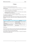
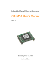
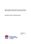
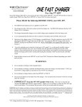
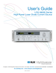
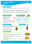
IS620P User Manual
Chapter 3 Wiring of Servo System
b) When output signal of the upper device is OC output:
Use 24 V internal
power supply for
NPN input:
+24V power
17
supply
Servo drive
24V
24 VDC
COM- 14
Use 24 V internal
power supply for
PNP input:
Servo drive
NPN
14
Servo drive
24V
+24V power 17
supply
COM+ 11
PNP
DI1(CMD1) 9 4.7 kΩ
COM+ 11
DI1(CMD1) 9 4.7 kΩ
COM-
COM-
Use 24 V external
power supply for
PNP input:
24V
+24V power supply 17
PNP
24V
+24V power 17
supply
COM+ 11
DI1(CMD1) 9 4.7 kΩ
COM+ 11
DI1(CMD1) 9 4.7 kΩ
NPN
Servo drive
Use 24 V external
power supply for
NPN input:
24 VDC
14
COM-
14
Note
PNP and NPN input cannot be applied in the same circuit.
2)
DO circuit
DO1 to DO5 circuits are the same. The following takes DO1 circuit as an example.
a) When input signal of the upper device is relay input:
Servo drive
5-24 VDC
Relay
7 DO1+
6 DO1-
Note
When the upper-level input is relay input, a flywheel diode must be installed; otherwise, the DO
terminals may be damaged.
- 53 -