1
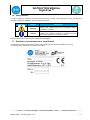
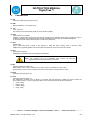
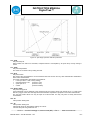
INSTRUCTION MANUAL DigitalTrak™ Instruction, installation and maintenance manual _____________________________________________________________________________________ STI S.r.l. – Via Dei Caravaggi 15, 24040 Levate (BG) – ITALY www.imi-critical.com Manual 4045 – rev.02 01/2015 – DT -1- INSTRUCTION MANUAL DigitalTrak™ SUMMARY 1. GENERAL INFORMATION 4 1.1 General warnings 1.2 Generalities 1.2.1 Applicable regulation 1.2.2 Terms and conditions 1.3 Manufacturer 1.4 Safety precautions 1.5 Packing list 1.6 Safety notices 1.7 Positioner and manufacturer’s identification 1.8 Declaration of incorporation 2. DESCRIPTION 4 4 4 4 4 4 4 5 5 6 7 2.1 Description of Function instruction 2.2 Performance 3. 4. TECHNICAL PARAMETERS ASSEMBLY 7 7 8 9 4.1 Dimensional drawings 4.2 Installation 4.3 Assembly for linear actuator 4.4 Assembly for rotary actuator 4.5 Installation of the Remote Sensor 4.6 Pneumatic connection 4.7 Electrical connections 4.7.1 Input electrical connection (Figure 6) 4.7.2 Feedback output module electrical connections (Figure 8): 4.7.3 Limit switch (option if present) electrical connections (Figure 9): 4.7.4 Connection of the remote sensor: 5. OPERATING REGULATION 9 9 10 11 12 12 13 13 14 14 15 15 5.1 Interface description 5.2 User menu 5.3 Calibration 5.3.1 Ready to initialize 5.3.2 Auto-tuning 5.4 Diagnosis 5.5 Alarm 5.5.1 Position sensor out of range 5.5.2 Zero point of position sensor too low 5.5.3 Span point of position sensor too high 5.5.4 Initialization error 5.5.5 Measurement span is insufficient 5.5.6 Valve position out of limit 5.5.7 User characteristics setting error 5.5.8 Position limit setting error 5.5.9 Feedback over limits 5.5.10 Input current out of work range 5.5.11 Actuator error 5.5.12 Memory error 5.5.13 Abnormal error 5.6 Parameter list 6. 7. PARAMETERS FAULT AND MAINTENANCE 15 16 17 17 17 19 19 19 19 20 20 20 20 20 20 21 21 21 21 21 21 23 26 7.1 Trouble shooting 7.2 Maintainance 8. Transport and storage 26 26 27 _____________________________________________________________________________________ STI S.r.l. – Via Dei Caravaggi 15, 24040 Levate (BG) – ITALY www.imi-critical.com Manual 4045 – rev.02 01/2015 – DT -2- INSTRUCTION MANUAL DigitalTrak™ _____________________________________________________________________________________ STI S.r.l. – Via Dei Caravaggi 15, 24040 Levate (BG) – ITALY www.imi-critical.com Manual 4045 – rev.02 01/2015 – DT -3- INSTRUCTION MANUAL DigitalTrak™ 1. GENERAL INFORMATION 1.1 General warnings This Instruction Manual is an integral part of the device, it should be carefully read before carrying out any operation and it should be kept for future references. This Instruction Manual covers only the DT positioner. This Instruction Manual is realized in accordance with the Directive 2006/42/CE. 1.2 Generalities STI S.r.l positioners are conceived, manufactured and controlled according to the Quality Control System in compliance with EN-ISO 9001 international regulation. 1.2.1 Applicable regulation UNI EN ISO 12100-1: 2005: Safety of machinery – Basic notions, general design principles. Part 1-Basic terminology, method. UNI EN ISO 12100-2: 2005: Safety of machinery – Basic notions, general design principles. Part 2-Technical principles and specification. 2006/42/EC: Machine directive. 2006/95/EC: Directive for low voltage equipment. 2004/108/EC: Directive for the electromagnetic compatibility. 1.2.2 Terms and conditions STI S.r.l. guarantees that all the items produced, if installed, used and subject to maintenance, are without material and manufacturing defects, and comply with specifications in force. The period of warranty is of one year, starting from the date of installation by the first user of the product, or of eighteen months as of the date of shipment to the first user, depending on which event occurs first. The warranty does not cover special products or components not covered by warranty in their turn by subcontractors, or materials that were used or installed inappropriately, which were modified or repaired by unauthorized staff. If the failure was caused by inappropriate installation, maintenance or use, or by irregular working conditions, the repairs will be charged according to the applicable fees. 1.3 Manufacturer With respect to Machinery Directive 2006/42/EC the Manufacturer of the described product, is STI S.r.l. as specified on nameplate. Address: STI S.r.l. Via Dei Caravaggi 15 24040 Levate (Bergamo) – ITALY 1.4 1) 2) 3) 1.5 1) 2) 3) 4) Safety precautions Throughout the operation of the positioner, including auto setup, do not touch it. Make sure to disconnect air supply before make any maintenance work on the positioner The products must be correctly installed, operated and maintained. Packing list DT Intelligent Electropneumatic valve Positioner. Mounting kit. User Manual. Ordered kits as option. _____________________________________________________________________________________ STI S.r.l. – Via Dei Caravaggi 15, 24040 Levate (BG) – ITALY www.imi-critical.com Manual 4045 – rev.02 01/2015 – DT -4- INSTRUCTION MANUAL DigitalTrak™ 1.6 Safety notices In order to make you better use this manual and ensure your safety, when debugging, running ,repairing this equipment, please pay attention to the use of following symbols: Symbol Slogan Explanation Warning Refers to the potential dangers, if can’t avoid, it may damage the product itself or the surrounding objects. (Hazardous materials). Caution Refers to the things which are useful or special neglected affecting the operating conditions or production function (Not contain dangerous or harmful situations). Please read this manual careful before installation and debugging. 1.7 Positioner and manufacturer’s identification It is forbidden to modify the information and the marks without previous written authorization by STI S.r.l. The following plate is fastened on the positioner housing: _____________________________________________________________________________________ STI S.r.l. – Via Dei Caravaggi 15, 24040 Levate (BG) – ITALY www.imi-critical.com Manual 4045 – rev.02 01/2015 – DT -5- INSTRUCTION MANUAL DigitalTrak™ 1.8 Declaration of incorporation _____________________________________________________________________________________ STI S.r.l. – Via Dei Caravaggi 15, 24040 Levate (BG) – ITALY www.imi-critical.com Manual 4045 – rev.02 01/2015 – DT -6- INSTRUCTION MANUAL DigitalTrak™ 2. DESCRIPTION DT Intelligent Electro pneumatic Positioner is a loop powered instrument produced by STI s.r.l. As a control part of the pneumatic valve set, DT Intelligent Electro pneumatic valve Positioner is widely used in petroleum, chemical, electric power, metallurgy, light industry and other fields of automation systems. DT Intelligent Electro pneumatic valve Positioner accepts the 4÷20mA valve setting signal from the control system; at the same time, it gets the actual valve signal through the location sensors; the two signals are compared by control software in order to control the feeding and exhaust of the gas to actuator, drive the valve to reach set point (as Figure 1). DT Intelligent Electro pneumatic valve Positioner is based on microprocessor technology. It can overcome friction and the imbalance power on the control valve well, and improve the response speed of control valve, which makes the position set rapidly and accurately. Figure 1: DT Intelligent Electropneumatic valve Positioner Principle 2.1 2.2 Description of Function instruction Self-adaptive function: automatic search the Zero and Span of valve, optimize the valve’s control parameters and improve the control precision. Configuration function: valve characteristics, action mode, dead band, stroke range, alarm events. Self-diagnosis function: show the value of input current, up / down running time, the dead band. Fault Mode: Fail safe or fail freeze. Valve position feedback function: 4~20mA DC current signal. Performance Position precision: 0.5% F.S. Manual setting operation allowed directly on the positioner. Small and compact design, modular construction. Automatic initialization, automatic diagnosis, valve characteristic. Reduced number of mechanical parts, good vibration resistance performance. Local parameter setting. Low power, low air consumption, low running cost. Using 4~20mA standard signal. _____________________________________________________________________________________ STI S.r.l. – Via Dei Caravaggi 15, 24040 Levate (BG) – ITALY www.imi-critical.com Manual 4045 – rev.02 01/2015 – DT -7- INSTRUCTION MANUAL DigitalTrak™ 3. TECHNICAL PARAMETERS PNEUMATIC INPUT / OUTPUT Air supply pressure 0.14 ÷ 0.7Mpa Air consumption in stable state < 36 L / H According to GB/T 13277.1 Size and density of particulates: Class 2 Oil concentration: Class 2 Dew point: Class 2 or at least 10K below surrounding environment Air quality Valve leakage < 0.6 L / H Actuator Single acting, double acting Input signal 4 ÷ 20mA, Loop Power Supply system Linear, equal percentage, quick open or freely adjustable M20x1.5 or NPT1/2 Output specialty Electrical connection Pneumatic connection Stroke DISPLAY LCD Accuracy 3 keys on the front panel Automatic calibrate the zero and span, dead band Show value of input current, travel time, dead band, etc. 0.5% F.S. Hysteresis 0.2% F.S. Linearity 0.5% F.S. Sensitivity 0.1% F.S. Repeatability 0.2% F.S. Dead band 0,1 ÷ 10% adjustable Input impedance 375 /20mA Environmental temperature -20 ÷ +70°C Environmental humidity 5 ÷ 95% RH Atmospheric pressure 86 ÷ 106KPa Enclosure degree of protection IP65 Weight 2 kg Dimension 170×96×96mm Shell material Aluminum alloy Manual OPERATE Self tuning Self diagnose PRECISION ENVIRONMENT APPEARANCE G ¼ or NPT1/4 Linear actuator 10 ÷ 100mm Rotary actuator 30 ÷ 105° 2x7 digitals, dimension: 22x38 mm Specification of Remote Sensor Working temperature -40 ÷ 100°C Bearable vibration condition 27 ÷ 200Hz @ 6g (gravity) Length of the cable 5m, 10m _____________________________________________________________________________________ STI S.r.l. – Via Dei Caravaggi 15, 24040 Levate (BG) – ITALY www.imi-critical.com Manual 4045 – rev.02 01/2015 – DT -8- INSTRUCTION MANUAL DigitalTrak™ 4. 4.1 ASSEMBLY Dimensional drawings Figure 2: Dimensional drawing 4.2 Installation To install correctly the rotate angle of the positioner stem should comply to the required reading angle range. Figure 3-a shows the positioner feedback indicator and the arrow marking indicator’s rotating range. Solid line shows the middle position of the indicator (when uninitialized, the LCD feedback value should be around 50.0 and the bottom row displays NOINIT). The two dotted line show the limit position of the feedback node rotate angle in normal use. Figure 3 _____________________________________________________________________________________ STI S.r.l. – Via Dei Caravaggi 15, 24040 Levate (BG) – ITALY www.imi-critical.com Manual 4045 – rev.02 01/2015 – DT -9- INSTRUCTION MANUAL DigitalTrak™ 4.3 Assembly for linear actuator For linear actuator SC63 with lever feedback: Figure 4-a The positioner is installed on the side of the actuator. Through the adjustable feedback lever actuator connected with actuator’s putting lever (as Figure 4-a), the installation steps as follows: Fix the support plate [# 2] on the actuator through the four screws [# 6+4+3]. Fix the positioner [# 17] on the plate through the four screws [# 7+8]. Connect the lever [#9] to the positioner shaft and insert the screw [#14] into the lever on the side of the lever. Move the actuator shaft to 50% to the stroke, rotate the lever [#9] perpendicular to the support plate, if necessary adjust the length of the treaded rod [#12] unloosing the nuts [#13], rotating the bar and fixing again the nuts. Adjust the rotate angle of the feedback lever so that it comply to the requirement in 4.2.1.and fix tight the screw [#14]. Move the actuator shaft from 0% of the stroke to 100% checking that there are not mechanical interference of the linkage components. For actuators with motion converter feedback linkage: Positioner installed on the side of the actuator. Through the motion converter STI model MC, connected with actuator’s shaft with rod and cam; the installation steps are the following Fix the support [# 1] on the motion converter with the four screws [# 3+455] Fix the positioner on the support [# 1] the four screws [# 6+7] _____________________________________________________________________________________ STI S.r.l. – Via Dei Caravaggi 15, 24040 Levate (BG) – ITALY www.imi-critical.com Manual 4045 – rev.02 01/2015 – DT - 10 - INSTRUCTION MANUAL DigitalTrak™ - Connect the upper lever to the positioner shaft and the lower [# 2] to the motion converter shaft. For motion converter adjustment please see Instruction manual 2051 Adjust the rotate angle of the feedback lever so that it comply to the requirement in 4.2.1.and fix tight the screw [#13] Move the actuator shaft from 0% of the stroke to 100% checking that there are not mechanical interference of the linkage components. Figure 4-b 4.4 Assembly for rotary actuator 7 1 2 3 1 2 3 6 5 4 7 8 9 108 9 10 11 11 12 12 6 5 4 Figure 5-a No. Amount Name Spec. 1 2 3 4 5 6 7 8 8 8 8 1 1 1 2 1 Washer Elastic washer socket cap screw set screw Feedback lever Bracket 2 Bracket 1 U shape feedback lever D6 D6 M6×12 M5×5 _____________________________________________________________________________________ STI S.r.l. – Via Dei Caravaggi 15, 24040 Levate (BG) – ITALY www.imi-critical.com Manual 4045 – rev.02 01/2015 – DT - 11 - INSTRUCTION MANUAL DigitalTrak™ 9 10 11 12 1 4 4 4 8 9 10 11 12 socket cap screw Socket cap screw Elastic washer Washer M6 M5×12 D5 D5 1 23 Figure 5-b The installation steps as follow: - Attach the Bracket 2 (6) to the positioner with socket cap screws (3), elastic washers (2) and washers (1). - Attach the feedback lever (4) to the shaft and fix with the set screw (5). - Attach the Bracket 1 (7) to the actuator with socket cap screws (10), elastic washers (11) and washers (12). - Attach socket cap screws (9) to the U shape feedback lever (8) and attach the U shape feedback lever (8) to the actuator. - Put the positioner carefully on the actuator. The pin of the feedback lever (4) should be in the through of the U shape feedback lever (8). Adjust the height of the positioner, lock screw on the pin of the feedback lever (4) and fix the positioner with socket cap screws (3), elastic washers (2) and washers (1). Adjust the rotate angle of the feedback lever so that it comply to the requirement in 4.2.1 4.5 Installation of the Remote Sensor The installation design of the remote sensor is the same as the positioner. Please fully refer to the installation of the positioner. 4.6 Pneumatic connection Pneumatic Connections is on the right of positioner, positioner provides two kind of connection types: G1 / 4 and NPT 1/4 (refer to ordering data), the specific type is marked on the shell, users can choose the type according to pipe to be connected. _____________________________________________________________________________________ STI S.r.l. – Via Dei Caravaggi 15, 24040 Levate (BG) – ITALY www.imi-critical.com Manual 4045 – rev.02 01/2015 – DT - 12 - INSTRUCTION MANUAL DigitalTrak™ Figure 6: Pneumatic Connection Installation Step: 1. Connect to the output of the DigitalTrak smart positioner to the input of the actuator. WARNING: Any fitting leakage is harmful to the good operation, use soapy water inspection air tightness of joint connection. 2. Connect the positioner’s input with the air supply. The compressed air through the positioner must be filtered and regulated. Air requirements: a) Air pressure must be 0.14 ~ 0.7 MPa, depending on the specific value of the actuator. b) Air supply must clean dry air with no, oil or other liquid / vapor. c) Air supply must be no corrosive. 3 d) The number of solid particles contained in Gas source should be less than 0.1 g/m , and particle diameter 3 should be less than 60um, oil content should be less than 10m g/m . e) The air dew point under work pressure should be at least 10 ℃ lower than its work positioner environment temperature. 4.7 Electrical connections Electrical connections should be strictly in accordance with the connection diagram, should be firmly secured, and not be loose. Cable connector has to be a standard waterproof connector. Diameter of the signal cable diameter should be at least 8mm and tighten the cover so that the IP protect level will not reduce. 4.7.1 Input electrical connection (Figure 6) Type: Loop Power Supply system Input signal: 4-20mA The min. working current: 3.6mA DC Input impedance: 350Ω _____________________________________________________________________________________ STI S.r.l. – Via Dei Caravaggi 15, 24040 Levate (BG) – ITALY www.imi-critical.com Manual 4045 – rev.02 01/2015 – DT - 13 - INSTRUCTION MANUAL DigitalTrak™ Figure 7: Electrical input connection 4.7.2 Feedback output module electrical connections (Figure 8): Feedback signal type: Loop Power Supply 4÷20mA Drift: ≤100ppm Scope of working: 3.6 ÷ 20.5 mA Precision: ≤1%F.S Working voltage: 12÷30V DC Figure 8: feedback output model electronic connection 4.7.3 Limit switch (option if present) electrical connections (Figure 9): Input voltage: Ui≤24V DC Input current: Ii≤2A Figure 9: Limit switch electronic connection _____________________________________________________________________________________ STI S.r.l. – Via Dei Caravaggi 15, 24040 Levate (BG) – ITALY www.imi-critical.com Manual 4045 – rev.02 01/2015 – DT - 14 - INSTRUCTION MANUAL DigitalTrak™ 4.7.4 Connection of the remote sensor: Positioner Remote Sensor Black PE +21 -22 Green Black Vref+ Vp Vref- Blue Red Blue +31 Green Red -32 Ground terminal 5. 5.1 OPERATING REGULATION Interface description Display: The LC display has two lines: in the normal mode the first line shows the position, the second line from left to right shows direction of the valve-action, the state of running and the setpoint; in the Configuration menu mode, the first line shows the parameter value, the second line from left to right shows parameter number, the parameter name. NOTE: If the positioner is operated in ranges with temperatures below -10°C the liquid crystal display becomes sluggish and the display refresh rate is reduced obviously. The positioner has three keys. 123- As Figure: operation mode key A/M [ENTER] decrease [DOWN] increase [UP] Figure10: Operation Interface NOTE: 1) Manual / automatic switch Automatic to manual: Click the button A/M, the second line of LCD shows "A". Manual to Automatic: click button A/M, the second line of LCD shows"M". _____________________________________________________________________________________ STI S.r.l. – Via Dei Caravaggi 15, 24040 Levate (BG) – ITALY www.imi-critical.com Manual 4045 – rev.02 01/2015 – DT - 15 - INSTRUCTION MANUAL DigitalTrak™ 2) Manual control In manual mode, hold down the button , valve position increase; at the same time hold down the , valve position fast increase. In manual mode, holding down a button, valve position decrease; at the same time hold down the , valve position fast decrease. 5.2 User menu 1) Enter user menu In the normal mode, to go to the Configuration menu, press the operation mode button “A/M”for at least 3 seconds. 2) Choose user menu In user menu state, the user can choose 4 different kind of menu: P1, P2, P3 and P4. Conversion of four kind of menu: when showing any of P1, P2, P3 and P4, press A/M, to choose parameters circularly (as Figure 11). Figure 11: Choose User Menu parameter Choosing the parameter of any kind of menu: Press the increase button , the menu turns forward circularly. Press the decrease button the menu turns backward circularly. Here display the contents of parameters: Two digit in the front of the below line show parameters number, letters in the back display the name of parameter. 3) Change user menu Press the button A/M to enter the parameter configure mode, the parameters on the screen will be blinking; such as For numerical parameters: Press the button parameter value will increase. Press the button for longer time, the parameter value increases quickly. Press the button , parameter value will decrease. Press the button for longer time, the parameter value quickly. For character parameters: _____________________________________________________________________________________ STI S.r.l. – Via Dei Caravaggi 15, 24040 Levate (BG) – ITALY www.imi-critical.com Manual 4045 – rev.02 01/2015 – DT - 16 - INSTRUCTION MANUAL DigitalTrak™ Press the button , parameter value move forward. Press the button , parameter value move reverse. For reset PRST, automatic initialization INIA and manual initialization parameters INIM: Press the button, LCD shows "STRT" on the first line, after 3 seconds it enter the state of their own. NOTE: In the menu state, if there is no operation 2 minutes, the valve positioner will return to normal state. 4) Exit user menu In user menu state: Press the button A/M for 3 seconds to exit the user menu and return to normal mode. 5.3 Calibration When smart electro-pneumatic valve Positioner installation is completed, it must be initialized. When initializing, the valve will open and close automatically, please check the working conditions and take measures to ensure that the valve movement does not affect the process and personal safety. There are two ways to initialize: automatic tuning and manual tuning. 5.3.1 Ready to initialize Check the positioner installation and electrical connection is in line with the requirement of chapter 4 of the manual. Connect the gas source and the power/ signal. Control the valve manually to run it from fully open to fully close and confirm the installation is correct. 5.3.2 1) Auto-tuning After electrical and pneumatic positioner connection, press and hold A/M more than 3 seconds to enter the user menu state. Displaying: 2) Press , up shows "N0", down shows " ", Displaying: 3) Press function key A/M, the down showing will be blinking , enter the parameter configure state. 4) Press for more than 3 seconds, up shows "STRT", enter the auto-tuning. Displaying: 5) The whole procedure goes from "STEP1" to "STEP5", and shows the current steps on the down line Displaying: 6) After tuning, up show the values of parameters, the down shows the "ED XXXX", XXXX means the relevant parameters of tuning. Displaying: press and hold A/M 3 seconds to return to normal state. _____________________________________________________________________________________ STI S.r.l. – Via Dei Caravaggi 15, 24040 Levate (BG) – ITALY www.imi-critical.com Manual 4045 – rev.02 01/2015 – DT - 17 - INSTRUCTION MANUAL DigitalTrak™ NOTE: In the process of tuning, press the function button A/M more than 3 seconds, can exit tuning state and enter automatically state 5.3.3 Manual tuning 1) Positioner is in normal state after power-on. Press and hold A/M for more than 3 seconds to enter the user menu state. Displaying: 2) Press to choose the parameter, till the second row shows " ". Displaying: 3) Press the button A/M, the down line will be blinking , enter the parameter amending state. Displaying: 4) Press for more than 3 seconds, up shows "STRT", then it enter the manual tuning. Down shows " ", Displaying: 5) Press or to choose the start point. Displaying: 6) Press A/M to confirm, At this time the down line shows " " Displaying: 7) Press or to choose the end point Displaying: 8) Press A/M to confirm, At this time the down line shows“ ” Displaying: 9) Press or ,and then release it when the feedback value is between zero and span. Displaying: 10) Press A/M to continue the procedure. The whole procedure is according to the "STEP1" to "STEP5", and shows the current steps on the down line. In the process of tuning, press the function key A/M for more than 3 seconds to exit tuning state and enter automatic state. 11) After tuning, up shows parameters value; the down shows the "ED XXXX", XXXX means the relevant tuned parameters. _____________________________________________________________________________________ STI S.r.l. – Via Dei Caravaggi 15, 24040 Levate (BG) – ITALY www.imi-critical.com Manual 4045 – rev.02 01/2015 – DT - 18 - INSTRUCTION MANUAL DigitalTrak™ 12) Press A/M for 3 seconds to return the normal state. 5.4 Diagnosis 5.4.1 Enter the state of diagnosis In normal state, press the button A/M and 3 seconds to enter the diagnosis state. Upper line displays the value of parameter; lower line displays the name of the parameter. Press the button , the parameter moves forward circularly Press the button , the parameter moves revise circularly 5.4.2 Exit the state of diagnosis In the state of diagnosis: Press the button A/M for 3 seconds to exit the diagnosis state and return to automatic state. 5.4.3 The auto-diagnostic parameter list of valve Positioner 5.5 5.5.1 No Parameters 01 02 Display Meaning Value/Range Default Unit CURR Input current 4.00~20.00 STRK Stroke range 0~100 100 mm/d mA 03 TUP Travel time up 0~200 10 S 04 TDW Travel time down 0~200 10 S 05 DBUP Dead band up 0.1~10.0 0.5 % 06 DBDW Dead band down -0.1~-10.0 -0.5 % 07 PUP Prediction up 0.1~100.0 0.2 % 08 PDW Prediction down -0.1~-100.0 -0.2 % 09 IMUP Pulse length up 0.1~200.0 10 ms 10 IMDW Pulse length down -0.1~-200.0 -10 ms 11 SSUP Step zone up 0.1~100.0 30.0 % 12 SSDW Step zone down -0.1~-100.0 -30.0 % Alarm Position sensor out of range In uninitialized state, if the position sensor goes out of the working range, it will display the error code "ADER": Display: 100. #ADER 0 Solution: Check whether installation of feedback components is accordance with 4.2.2 or 4.2.3 in this manual. Fine-tune the installation bracket position. 5.5.2 Zero point of position sensor too low In uninitialized state, if the feedback position value is less the 5.0, it will display the error code "DOWN": Display: Solution: Check whether installation of feedback components is accordance with 4.2.2 or 4.2.3 in this manual. Fine-tune the installation bracket position. _____________________________________________________________________________________ STI S.r.l. – Via Dei Caravaggi 15, 24040 Levate (BG) – ITALY www.imi-critical.com Manual 4045 – rev.02 01/2015 – DT - 19 - INSTRUCTION MANUAL DigitalTrak™ 5.5.3 Span point of position sensor too high In uninitialized state, if the feedback position value is less the 5.0, it will display the error code "DOWN": Display: Solution: Check whether installation of feedback components is accordance with 4.2.2 or 4.2.3 in this manual. Fine-tune the installation bracket position. 5.5.4 Initialization error When the positioner Initialization, the parameters setting or the actuator acting error. Display: Solution: Start manual initialization Re-set parameters 5.5.5 Measurement span is insufficient When the positioner Initialization, the feedback range is less than 25.0. Display: Solution: Adjust the slider on the control rod components, making the feedback value range greater than 25.0. 5.5.6 Valve position out of limit When the valve is running, valve position goes out of limit position. Display: Solution: Check the feedback lever of the positioner installation. Check the connection of positioner and actuator. Check the connection of the bracket and actuator. Adjust the valve position limit values. Re-initialize the positioner. 5.5.7 User characteristics setting error When the user defines the characteristics profile of the valve, the characteristics is non-monotonic up / down. Display: Solution: Re-set the parameters. 5.5.8 Position limit setting error When the value of 36 YA is greater than or equal to the value of 37 YE will display the error code "LIMSE": Display: 50. LIMSE 0 Solution: Set the value of 36 YA smaller than the value of 37 YE. _____________________________________________________________________________________ STI S.r.l. – Via Dei Caravaggi 15, 24040 Levate (BG) – ITALY www.imi-critical.com Manual 4045 – rev.02 01/2015 – DT - 20 - INSTRUCTION MANUAL DigitalTrak™ 5.5.9 Feedback over limits Feedback value is> 110% or <-10%. Display: Solution: Check feedback sensor and, if necessary, replace the sensor. Re-initialize the positioner. 5.5.10 Input current out of work range If the input current value is greater than 21mA(>110%) or less than 3.8mA (<-10%). Display: Solution: Check the input signal. 5.5.11 Actuator error For some reason, the positioner cannot drive the valve to a specific position. Display: Solution: Cleaning valve. Check the valve connected institutions. 5.5.12 Memory error When the memory of the positioner has error, display: Display: 100. EpeR 0 Solution: Disconnect the signal line and reconnect the signal line. 5.5.13 Abnormal error When there is hardware error internal hardware of positioner, Display: Solution: Inform supplier to solve the problem. 5.6 Parameter list Parameter Show code Function Content / Scope Factory Settings UM P1 01 INIA 02 INIM Initialize (automatic): Not start /Start Initialize(Manual): Not start /Start NO/STRT NO NO/STRT NO LINE/TURN LINE 03 04 TYPE The executive body types: linear actuator _____________________________________________________________________________________ STI S.r.l. – Via Dei Caravaggi 15, 24040 Levate (BG) – ITALY www.imi-critical.com Manual 4045 – rev.02 01/2015 – DT - 21 - INSTRUCTION MANUAL DigitalTrak™ / rotary actuator 05 AUTO 0.1÷10.0 AUTO 0.1 ÷100.0 06 DEBA controller dead 07 PRED Predict value PRST restore the factory settings: not start / factory set to start NO/STRT NO 08 AUTO % AUTO % P2 09 SDIR Control input signal and valve-relations RISE/FALL RISE 010 SPRA Sub-control point 0.0 ÷100.0 0.0 % 011 SPRE At the end of the sub- control 0.0 ÷100.0 100.0 % 012 TSUP AOTU 0÷400 AUTO s 013 TSDO AOTU 0÷400 AUTO s 014 SFCT LINE 1:30 30:1 FrEE LINE 015÷035 SP00÷S P10 Valve to increase the value of a given damping Valve to reduce the value of a given damping Valve Special Linearity -equal percentage open soon User define ~ User define valve special profile 0.0 ÷100.0 % YA Working under the valve-limits 0.0 ÷100.0 0.0 % YE Place limits on the work of the valve Valve-positive and negative feedback effect 0.0 ÷100.0 RISE/FALL 100.0 % P3 036 037 038 YDIR 039 YCDW "Compactness close " values down 040 YCUP "Compactness close " values up 041 SAFE 042 BIN OFF 0.0 ÷49.9 OFF 50.1 ÷100.0 RISE OFF % OFF % OFF / KEEP / CLOSE / 0.1÷99..9 / OPEN OFF % ON/OFF OFF FAULT NA NAB LMVPT HMVPT FAULT 0.0 ÷100.0 0.0 A/M LSET HSET A/M P4 043 DO1 044 SW1 045 DO2 Safe valve: Holding / wide clearance / Settings / wide-open Input switching functions: start-safety valve Switch output function: Fault alarm Fault + Non-auto Fault + Non-auto+BIN Under setting value Higher than the setting value setting value Switch output function: Auto/ Manual Under setting value Higher than the setting value setting value % 046 SW2 0.0 ÷100.0 0.0 % 047 AMIN Min output current 4.0÷20.0 4.0 mA 048 AMAX Max output current 4.0÷20.0 20.0 mA 049 ADIR Current output aspect RISE/FALL RISE _____________________________________________________________________________________ STI S.r.l. – Via Dei Caravaggi 15, 24040 Levate (BG) – ITALY www.imi-critical.com Manual 4045 – rev.02 01/2015 – DT - 22 - INSTRUCTION MANUAL DigitalTrak™ 6. PARAMETERS 01. INIA Automatic calibration (see chapter 5.3.2) 02. INIM Manual calibration ( see chapter 5.3.3) 04. TYPE Type of actuator. The actuator is a linear actuator (LINE) or rotary actuator (TURN). 06. DEBA Dead band of the controller If dEbA = AUto,the value of dead zone will change according to the operation status during operation. If there is oscillation, the dead zone will gradually increase, and gradually decrease after the oscillation disappears. In the other discrete settings the fixed value is used for the dead zone. 07. PRED Predict value When control-loop gives a signal to the actuator, it judge the direct running value of actuator, when PRED=AUTO, generally predict value confirm with the request of control-loop under auto-mode 08. PRST Preset (factory setting) Establishing the default value and resetting the initialization NOTE: The positioner must be re--initialized after ”Preset”. All previously determined maintenance parameters are cleared. 09.SDIR Setpoint direction(see figure 12) When SDIR is “rise” , 4mA Correspond to 0%-valve, 20mA is Correspond to 100%-valve, when SDIR is set “fall”, 4mA is correspond to 100%-valve, 20mA is correspond to 0%-valve. 010.SPRA Split range start (see figure 12) 011.SPRE Split range end (see figure 12) The parameters “10.SPRA” and “11.SPRE” in connection with the parameter “9.SDIR” are used to restrict the active setpoint range. In this way split range tasks can be solved with the following characteristics. rising / falling falling / rising falling / falling rising / rising _____________________________________________________________________________________ STI S.r.l. – Via Dei Caravaggi 15, 24040 Levate (BG) – ITALY www.imi-critical.com Manual 4045 – rev.02 01/2015 – DT - 23 - INSTRUCTION MANUAL DigitalTrak™ Figure 12: Split range-operation with two positioners 012. TSUP Set point ramp UP When switch from manual to automatic, bumpless switch is accomplish by set point ramp. Factory setting is AUTO. 013. TSDO Set point ramp DOWN The same as 12.TSUP. Factory setting is AUTO. 014. SFCT Set point function Non--linear valve characteristics can be linearized with this function and any flow characteristics simulated in linear valve characteristics. Four valve characteristics are stored in the positioner Linear (14.SFCT = LINE, factory setting) equal percentage 1:30 (14.SFCT=1:30) quick open 30:1 (14.SFCT=30:1) custom (14.SFCT=FREE) 015. SP00 to SP20 Set point turning points A flow parameter can be assigned to the respective set point turning value at an interval of 10 %. These points lead to a polygon chain with 10 straight lines which therefore represents a projection of the valve characteristic. The set point vertex values can only be input at 14.SFCT=FrEE. You may only enter a strictly monotonous characteristic. 036. YA Valve position limiting start 037. YE Valve position limiting end Valve travel range can be limited by setting YA and YE. YE must always be set greater than YA. _____________________________________________________________________________________ STI S.r.l. – Via Dei Caravaggi 15, 24040 Levate (BG) – ITALY www.imi-critical.com Manual 4045 – rev.02 01/2015 – DT - 24 - INSTRUCTION MANUAL DigitalTrak™ 038. YDIR Valve position feedback direction When YDIR = RISE, the valve-potentiometers’ resistance value is increased, which means increasing the valveopening, When YDIR = FALL, the valve-potentiometers’ resistance value is reduced, which means increasing the valveopening. 039. YCDW Value for tight closing When the set point is smaller than YCDW value, position will drive the valve to position 0%. This function can reduce the erosion of high speed medium on spool head. 040. YCUP Value for tight closing When the set point is smaller than YCDW value, position will drive the valve to position 100%. This function can reduce the erosion of high speed medium on spool head. YCDO must always be set to be smaller than YCUP. 041. SAFE Only when 31.BIN is set to be ON, Safety valve is effective If binary input is 0, valve will be drive to the position specified by this value. 042. BIN Binary input functions: enable/disable safe position function. 043. DO1 Digit output function 1 When positioner detected set fault, channel 1(DO1) of binary output module state is "high". 044 SW1 DO1 set value When DO1 = LSET, valve position is smaller than the SW1, channel 1(DO1) of binary output module state is "high". When DO1 = HSET, valve position is greater than the SW1, channel 1(DO1) of binary output module state is "high". 045 DO2 Digit output function 2 When positioner detected set fault, channel 2(DO2) of binary output module state is "high". 046 SW2 DO2 set value When DO2 = LSET, valve position is smaller than the SW1, channel 2(DO2) of binary output module state is "high". When DO2 = HSET, valve position is greater than the SW1, channel 2(DO2) of binary output module state is "high". 047 AMIN Min output current. Min output current for the 0% position. 048 AMAX Max output current. Max output current for the 100% position. 049 ADIR Relation between the output current of position feedback module and valve position. There are two choices: rise and fall. When choosing rise, output current will be 4mA when valve position is 0%; output current will be 20mA when valve position is 100%. When choosing fall, the result will be opposite. _____________________________________________________________________________________ STI S.r.l. – Via Dei Caravaggi 15, 24040 Levate (BG) – ITALY www.imi-critical.com Manual 4045 – rev.02 01/2015 – DT - 25 - INSTRUCTION MANUAL DigitalTrak™ 7. FAULT AND MAINTENANCE 7.1 Trouble shooting When positioner failed, follow these steps to eliminate fault, If you cannot solve the fault according to steps as bellow, please contact STI. Fault Actuator no action in manual /auto state Actuator does not move or moves slowly Move frequently(not oscillation) Reason Action to be taken Air pressure too low Air pressure adjustment > 0.14MPa Actuator jammed Exit initialization before finish Solve problem of actuator jammed Regulate the air pressure to above 0.14MP Re-initialize Leakage in air loop Check the air pipes Air pressure low Contact manufacturer if positioner leak Oscillation Valve cannot be fully opened or closed User configuration incorrect Set larger dead band, larger prediction Volume of actuator is too small Hysteresis is large, feedback device is not connected correctly, gap between the feedback pole slider and the U-shaped feedback lever is too large Set larger dead band, larger prediction Air pressure too low Increase air pressure Initialization data incorrect (physical limit during initialization or not initialized Re-initialize Position limit is set Check user configuration Tighten close not set No display Exhaust not smooth No position feedback current Feedback current mismatch actual position Position display on LCD mismatch actual position 7.2 1) Signal too small(<2mA) Electrical connection terminal screws loose Main board failed Bracket covers the exhaust Position feedback module failed No external power, position feedback module not work External wiring polarity Position feedback module failed Calibration of module drift Actuator travel range mismatch the scale Adjust installation of bracket or bracket position and re-initialize Active tighten close function in user menu Check input signal Tighten the terminal screws Change the main board Drill a hole on the bracket over the exhaust Change the module Provide 24V power to the module Rewire Change the module Tune the module potentiometer Manual initialize Maintainance Positioner is a instrument which should be regularly maintained. The air supply of positioner should be kept dry and clean. Regularly exhaust water and pollution of the regulator connecting the positioner in order to keep the positioner normally. _____________________________________________________________________________________ STI S.r.l. – Via Dei Caravaggi 15, 24040 Levate (BG) – ITALY www.imi-critical.com Manual 4045 – rev.02 01/2015 – DT - 26 - INSTRUCTION MANUAL DigitalTrak™ 2) 3) 8. Feedback connection may be loose due to long term work. Check the feedback connection regularly. If loose, tighten at once and decide whether to initialize or not according error of zero and span. In order to see whether the positioner is normal, keep the pressure gauge clear. Transport and storage 1) 2) 3) 4) Check whether all kinds of sign are integrality, fully, and the package is firm before storage. Finally, check the reliability and safety of enswathement. The transport should be light disposal, prohibit impacting, compression, and damp. Stored at -20 ÷ 80°C, relative humidity should be no more than 90% of the room, the air should not contain harmful and corrosion impurities instrument. Place according to the box’s surface marker, do not reverse. Information in this manual is protected by copyright. All rights are reserved. No part of this manual and relevant mentioned and/or enclosed documentation may be reproduced without written authorization by STI S.r.l. STI S.r.l. is not responsible for possible damage to people, equipment or data which might arise from incorrect use of the product to which the manual is referred. Information in this document may be modified at any time without notice. _____________________________________________________________________________________ STI S.r.l. – Via Dei Caravaggi 15, 24040 Levate (BG) – ITALY www.imi-critical.com Manual 4045 – rev.02 01/2015 – DT - 27 -